JP6605906B2 - Cargo lift ladder - Google Patents

Cargo lift ladder Download PDF

Info

Publication number
JP6605906B2
JP6605906B2 JP2015199055A JP2015199055A JP6605906B2 JP 6605906 B2 JP6605906 B2 JP 6605906B2 JP 2015199055 A JP2015199055 A JP 2015199055A JP 2015199055 A JP2015199055 A JP 2015199055A JP 6605906 B2 JP6605906 B2 JP 6605906B2
Authority
JP
Japan
Prior art keywords
column
ladder
wheel
support
loading platform
Prior art date
Legal status (The legal status is an assumption and is not a legal conclusion. Google has not performed a legal analysis and makes no representation as to the accuracy of the status listed.)
Active
Application number
JP2015199055A
Other languages
Japanese (ja)
Other versions
JP2017071951A (en
Inventor
一郎 與那原
Original Assignee
ジャパン スチールス グループ株式会社
Priority date (The priority date is an assumption and is not a legal conclusion. Google has not performed a legal analysis and makes no representation as to the accuracy of the date listed.)
Filing date
Publication date
Application filed by ジャパン スチールス グループ株式会社 filed Critical ジャパン スチールス グループ株式会社
Priority to JP2015199055A priority Critical patent/JP6605906B2/en
Publication of JP2017071951A publication Critical patent/JP2017071951A/en
Application granted granted Critical
Publication of JP6605906B2 publication Critical patent/JP6605906B2/en
Active legal-status Critical Current
Anticipated expiration legal-status Critical

Links

Images

Description

本発明は、荷物運搬車両の荷台に作業者が昇降するための荷台昇降用梯子に関し、特に、荷台の上方に親綱を張り渡すようにした荷台昇降用梯子に関する。   The present invention relates to a loading platform raising / lowering ladder for an operator to move up and down on a loading platform of a load carrying vehicle, and more particularly, to a loading platform lifting / lowering ladder configured to stretch a master rope above a loading platform.

トラックやトレーラ等の荷物運搬車両の荷台に、作業者が荷物を積み込んだり、積み込まれた荷物を荷下ろしたりするときには、作業者は荷台に乗り込んで作業を行うことがある。作業者が荷台に安全に乗り込むようにするために梯子が使用される。特に、荷台が高い荷物運搬車両においては、荷台への作業者の安全な上り下りには、梯子が必須である。   When an operator loads or unloads a loaded load on a loading platform of a load carrying vehicle such as a truck or a trailer, the worker may work on the loading platform. Ladder is used to allow the operator to safely get on the platform. In particular, in a load carrying vehicle with a high loading platform, a ladder is indispensable for the safe ascending and descending of the worker to and from the loading platform.

作業者が荷台に乗って荷物の積み込み作業や、荷台に積み込まれた荷物の荷下ろし作業を行うときには、作業者の安全のために、荷台の上には親綱が荷台の上方に張り渡される。作業者は腰に装着したベルトにロープの基端部を取り付け、ロープの先端部に設けられたフックを親綱に引っ掛けた状態で荷物の積み込みと、荷下ろし作業を行う。このため、荷台の高い荷物運搬車両の荷台に荷物の積み込み作業や荷下ろし作業を行うときには、梯子と親綱とが使用される。   When an operator gets on the carrier and loads the cargo, or unloads the cargo loaded on the carrier, the master rope is stretched above the carrier for the safety of the operator. . The operator attaches the base end of the rope to the belt attached to the waist, and loads and unloads the luggage with the hook provided at the tip of the rope hooked on the master rope. For this reason, a ladder and a master rope are used when loading and unloading work on a load carrier of a load carrier vehicle having a high load platform.

荷物運搬車両には親綱を支持する支柱が設けられていないので、特許文献1〜3に記載されるように、荷物運搬車両に親綱を支持するための支柱が装着される。   Since the luggage carrier vehicle is not provided with a support for supporting the master rope, as described in Patent Documents 1 to 3, a pillar for supporting the master rope is attached to the luggage carrier vehicle.

特開2015−70980号公報JP-A-2015-70980 特開2009−61191号公報JP 2009-61191 A 特開2010−220916号公報JP 2010-220916 A

特許文献1には、トラックの車輪が乗り上げられる基台と、基台の上に取り付けられた支柱とを有する親綱張設具が記載されており、親綱が装着される親綱取り付け環つまりフックが支柱の上部に取り付けられている。特許文献2は、車輪が乗り上げられる踏み板と、踏み板の上に取り付けられる基部支柱とを有する親綱架設装置が記載されており、基部支柱には昇降支柱が装着され、昇降支柱の上端部には綱取付具が設けられている。特許文献3は、車輪が乗り上げる台座部と、台座部に取り付けられる支柱本体とを有する親綱張架装置が記載されており、支柱本体には上下動自在に綱掛け部が設けられている。   Patent Document 1 describes a master rope tensioning tool having a base on which wheels of a truck are mounted and a column attached on the base. A hook is attached to the top of the column. Patent Document 2 describes a master rope erection device having a tread board on which wheels are climbed and a base column attached on the tread plate. The base column is equipped with a lifting column, and the upper end of the lifting column is attached to the upper column. A leash fitting is provided. Patent Document 3 describes a parent rope tensioning device having a pedestal portion on which a wheel rides and a column main body attached to the pedestal portion, and the column main body is provided with a rope hanging portion that can move up and down.

上述した特許文献に記載された従来の支柱は、親綱を支持するためのものであり、作業者が荷台に上り下りするためには、予め荷物運搬車両に梯子を立て掛ける必要がある。つまり、梯子を荷物運搬車両に立て掛ける作業と、親綱を支持するための支柱を荷物運搬車両に装着する作業とが必要であり、荷台への荷物の積み込み作業と、荷物の積み卸し作業には時間がかかり、その作業性を向上させることができない。   The conventional support described in the above-mentioned patent document is for supporting the master rope, and it is necessary for the worker to stand up a ladder on the luggage transport vehicle in advance in order to ascend and descend the platform. In other words, it is necessary to hang the ladder against the luggage carrier vehicle and to attach a support for supporting the master rope to the luggage carrier vehicle. For loading and unloading of luggage on the carrier, It takes time and the workability cannot be improved.

本発明の目的は、荷物運搬車両の荷台への荷物の積み込みと積み卸し作業の作業性を向上させることにある。   An object of the present invention is to improve the workability of loading and unloading work on a loading platform of a load carrying vehicle.

本発明の荷台昇降用梯子は、主支柱が取り付けられ、荷物運搬車両の車輪に締結される支柱支持台と、前記車輪に対して前記主支柱を介して反対側に突出して前記主支柱に取り付けられる支持具と、前記支持具に取り付けられ、前記主支柱に沿って伸びる梯子支柱と、前記主支柱と前記梯子支柱との間に、前記荷物運搬車両の車幅方向に伸びて設けられる複数の踏み材と、前記荷物運搬車両の荷台の上方に張り渡される親綱が掛けられる綱掛け部を備え、前記主支柱に軸方向に摺動自在に装着される親綱支柱と、前記支持具の先端に前記荷物運搬車両の側面に沿う方向に延びて取り付けられる脚部と、前記脚部の両端部に設けられるキャスターと、を有し、前記キャスターのみが地面に接触するように傾斜させ、前記キャスターにより移動させることができる。 The ladder for raising and lowering the loading platform according to the present invention is attached to the main column by protruding from the main column to the opposite side to the wheel with a column supporting table to which the main column is attached and fastened to the wheel of the load carrying vehicle. A support member that is attached to the support member and extends along the main support column, and a plurality of support members that extend in the vehicle width direction of the luggage carrier vehicle between the main support column and the ladder support column. A footrest, a leash rack portion on which a main rope stretched above a loading platform of the luggage carrier vehicle is hung, and a main rope strut that is slidably mounted on the main strut in an axial direction ; a leg portion attached to extend in a direction along the side surface of the load carrying vehicle to tip, have a, and casters provided at both end portions of the legs, is inclined so that only the casters contact the ground, the Moved by casters Rukoto can.

荷台昇降用梯子を用いて作業者は地盤と荷台との間を上り下りすることができるとともに、親綱支柱の先端に親綱を掛け渡して親綱を用いて荷物の積み卸し作業を行うことができる。これにより、トラック等の荷物運搬車両の荷台への荷物の積み込みと積み卸し作業の作業性を向上させることができる。荷台昇降用梯子を荷物運搬車両の側面に配置すると、梯子を構成する踏み材は、車幅方向を向くので、踏み材と荷台との乗り移りを容易かつ安全に行うことができる。さらに、キャスターのみが地盤に接触するように傾斜させると、作業者は容易に荷台昇降用梯子を任意の位置にキャスターのみにより移動させることができる。したがって、荷物の積み卸しを行う作業場の片隅に保管された荷台昇降用梯子を、トラックの側面にまで容易に搬送することができる。 Using the ladder for raising and lowering the loading platform, the worker can ascend and descend between the ground and the loading platform, and carry out the loading and unloading work using the parent rope by hanging the parent rope on the tip of the parent rope column. Can do. Thereby, the workability of loading and unloading work of a load on a loading platform of a load carrying vehicle such as a truck can be improved. When the loading platform raising / lowering ladder is disposed on the side surface of the load carrying vehicle, the stepping material constituting the ladder faces in the vehicle width direction, so that the stepping material and the loading platform can be easily and safely transferred. Furthermore, when the vehicle is inclined so that only the casters are in contact with the ground, the operator can easily move the loading platform elevating ladder to an arbitrary position by using only the casters. Therefore, the loading platform raising / lowering ladder stored in one corner of the work place where the cargo is loaded and unloaded can be easily transported to the side of the truck.

トラックに装着された荷台昇降用梯子を示す正面図である。It is a front view which shows the ladder for a loading platform raising / lowering with which the truck was mounted | worn. 図1に示された荷台昇降用梯子の拡大正面図である。FIG. 2 is an enlarged front view of the loading platform elevating ladder shown in FIG. 1. 図2の右側面図である。FIG. 3 is a right side view of FIG. 2. 作業者により移動している状態における荷台昇降用梯子の側面図である。It is a side view of the loading platform raising / lowering ladder in the state which is moving by the operator. 図3の平面図である。FIG. 4 is a plan view of FIG. 3. 他の形態の荷台昇降用梯子を示す正面図である。It is a front view which shows the ladder for raising / lowering a loading platform of another form. 図6の右側面図である。FIG. 7 is a right side view of FIG. 6. 図7の平面図である。FIG. 8 is a plan view of FIG. 7. さらに他の形態の荷台昇降用梯子を示す正面図である。It is a front view which shows the ladder for raising / lowering a load carrier of another form. 図9の右側面図である。FIG. 10 is a right side view of FIG. 9. 図10の平面図である。It is a top view of FIG. (A)は図10におけるA−A線断面図であり、(B)は支柱支持台と車輪との締結を解除した状態におけるA−A線断面図である。(A) is the sectional view on the AA line in FIG. 10, (B) is the sectional view on the AA line in the state which canceled the fastening with a support | pillar support stand and a wheel. さらに他の形態の荷台昇降用梯子を示す正面図である。It is a front view which shows the ladder for raising / lowering a load carrier of another form. 図13の右側面図である。FIG. 14 is a right side view of FIG. 13. 図14の平面図である。FIG. 15 is a plan view of FIG. 14.

以下、本発明の実施の形態を図面に基づいて詳細に説明する。それぞれの実施の形態においては、共通性を有する部材には同一の符号が付されている。   Hereinafter, embodiments of the present invention will be described in detail with reference to the drawings. In each embodiment, the same code | symbol is attached | subjected to the member which has commonality.

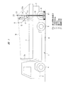
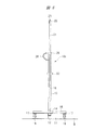
図1〜図5は、荷台昇降用梯子の一つの形態を示す。図1に示されるように、荷物運搬車両であるトラック1は、運転席が設けられた車両前部2とその後方の荷台3とを有し、車両前部2側には前輪4が設けられ、荷台3側には後輪5、6が設けられている。荷台3の左右側面と後面には煽り板7が開閉自在に装着されている。図1は、煽り板7が閉じられた状態つまり起立した状態のトラック1の側面に荷台昇降用梯子10aが配置された状態を示す。   1-5 shows one form of the ladder for raising / lowering the loading platform. As shown in FIG. 1, a truck 1 that is a load carrying vehicle has a vehicle front portion 2 provided with a driver's seat and a loading platform 3 behind the vehicle, and a front wheel 4 is provided on the vehicle front portion 2 side. The rear wheels 5 and 6 are provided on the cargo bed 3 side. On the left and right side surfaces and the rear surface of the loading platform 3, a cover plate 7 is mounted so as to be freely opened and closed. FIG. 1 shows a state in which a loading platform elevating ladder 10a is arranged on the side surface of the track 1 in a state where the cover plate 7 is closed, that is, in a standing state.

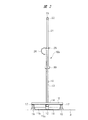
荷台昇降用梯子10aは、トラック1の後輪6に固定される支柱支持台11を有する。支柱支持台11は、図3および図4に示されるように、荷積みや荷下ろしをする作業場の地盤Bに接触する水平片11aと、これに対して直角となった垂直片11bとが一体となったL字型の形鋼により形成されている。水平片11aの上面には円筒形状の固定具12が固定されており、固定具12には丸パイプからなる主支柱13が固定される。   The loading platform elevating ladder 10 a includes a support column 11 that is fixed to the rear wheel 6 of the truck 1. As shown in FIGS. 3 and 4, the support column 11 is composed of a horizontal piece 11 a that contacts the ground B of the work place for loading and unloading, and a vertical piece 11 b that is perpendicular to the horizontal piece 11 a. The L-shaped steel is formed. A cylindrical fixture 12 is fixed to the upper surface of the horizontal piece 11a, and a main column 13 made of a round pipe is fixed to the fixture 12.

固定具12にはこれに対して直角方向に伸びる支持具14が取り付けられており、支持具14は横断面が四角形の角パイプにより形成されている。支持具14の先端部には、支持具14に対して直角方向に伸びる脚部15が固定されており、脚部15はL字型の形鋼により形成され、図2に示されるように、脚部15の長手方向中央部で支持具14の上面に固定される。脚部15の両端部には車輪つまりキャスター16が装着される。キャスター16は、脚部15に固定されるキャスター支持金具17に回転自在に装着され、キャスター16により荷台昇降用梯子10aを走行させることができる。固定具12と支持具14との間に補強板を溶接すると、固定具12と支持具14の取付強度を高めることができる。   A support tool 14 extending in a direction perpendicular to the fixing tool 12 is attached to the fixing tool 12, and the support tool 14 is formed of a square pipe having a square cross section. A leg 15 extending in a direction perpendicular to the support 14 is fixed to the tip of the support 14, and the leg 15 is formed of an L-shaped shape steel, as shown in FIG. The leg 15 is fixed to the upper surface of the support 14 at the center in the longitudinal direction. Wheels, that is, casters 16 are attached to both ends of the leg portion 15. The caster 16 is rotatably mounted on a caster support bracket 17 fixed to the leg portion 15, and the loading platform elevating ladder 10 a can be run by the caster 16. When a reinforcing plate is welded between the fixture 12 and the support 14, the mounting strength of the fixture 12 and the support 14 can be increased.

支持具14の先端には梯子支柱18が取り付けられており、梯子支柱18は図3および図4に示されるように主支柱13に平行となっている。梯子支柱18と主支柱13との間には、それぞれ水平方向に伸びる棒状の複数の踏み材19が設けられている。図示する荷台昇降用梯子10aは、5つの踏み材19を備えているが、踏み材19の本数は任意に設定される。   A ladder column 18 is attached to the tip of the support 14, and the ladder column 18 is parallel to the main column 13 as shown in FIGS. 3 and 4. Between the ladder column 18 and the main column 13, a plurality of bar-like stepping members 19 extending in the horizontal direction are provided. The loading platform elevating ladder 10a shown in the figure includes five treads 19, but the number of treads 19 is arbitrarily set.

主支柱13には、親綱支柱21が上下方向つまり軸方向に摺動自在に装着される。親綱支柱21は主支柱13よりも小径の丸パイプからなり主支柱13の内部を軸方向に摺動する。親綱支柱21の上端部つまり先端部には綱掛け部22が設けられている。綱掛け部22は貫通孔23を有し、綱掛け部22には、図1に示されるように、親綱Wが張り渡される。図1に示される親綱Wは、荷台昇降用梯子10aの上端部で支持されて、先端部が荷台3の先端部に設けられたガードフレーム3aに取り付けられ、他端部が荷台3の後端部に取り付けられる。これにより、荷台3の側面の上方には、親綱Wが張り渡される。作業者Pは、ベルトにロープQを装着し、ロープQの先端に設けられたフックRを親綱Wに引っ掛けて荷積みや荷下ろしの作業を行うことができる。これにより、作業者Pはこれらの作業を安全に行うことができる。   The main strut 13 is fitted with a master rope strut 21 so as to be slidable in the vertical direction, that is, in the axial direction. The master rope column 21 is made of a round pipe having a smaller diameter than the main column 13 and slides in the main column 13 in the axial direction. A rope hook 22 is provided at the upper end, that is, the tip of the main rope support 21. The tightrope 22 has a through hole 23, and a master rope W is stretched over the tightrope 22 as shown in FIG. 1. The master rope W shown in FIG. 1 is supported by the upper end of the loading platform raising / lowering ladder 10 a, the distal end is attached to the guard frame 3 a provided at the distal end of the loading platform 3, and the other end is the rear of the loading platform 3. Attach to the end. Thereby, the master rope W is stretched over the side surface of the loading platform 3. The worker P can load and unload work by attaching the rope Q to the belt and hooking the hook R provided at the tip of the rope Q on the master rope W. Thereby, the worker P can perform these operations safely.

綱掛け部22の高さは、親綱支柱21を上下方向に移動させることにより調節される。調節された綱掛け部22の位置を固定するために、図3に示されるように、親綱支柱21には、長手方向に所定の間隔を隔てて複数の取付孔24が設けられている。位置決めピン25がチェーン26により主支柱13に装着されており、位置決めピン25は、それぞれの取付孔24に貫通して取り付けることができる。位置決めピン25を取付孔24に取り付けると、位置決めピン25の両端部が主支柱13の上端面に当接し、綱掛け部22の位置が固定される。   The height of the leash portion 22 is adjusted by moving the parent leash strut 21 in the vertical direction. In order to fix the adjusted position of the rope-hanging portion 22, as shown in FIG. 3, the main rope support 21 is provided with a plurality of attachment holes 24 at predetermined intervals in the longitudinal direction. A positioning pin 25 is attached to the main column 13 by a chain 26, and the positioning pin 25 can be attached through each attachment hole 24. When the positioning pin 25 is attached to the attachment hole 24, both end portions of the positioning pin 25 come into contact with the upper end surface of the main column 13, and the position of the leash portion 22 is fixed.

主支柱13とこれに対して軸方向に上下動自在に装着される親綱支柱21とにより、全体的に伸縮自在の支柱が形成され、綱掛け部22の高さが調整される。なお、主支柱13と親綱支柱21は、それぞれ丸パイプにより形成されているが、角パイプにより形成するようにしても良い。   The main strut 13 and the parent rope strut 21 that is mounted so as to be movable up and down in the axial direction with respect to the main strut 13 form a stretchable strut as a whole, and the height of the leash section 22 is adjusted. In addition, although the main support | pillar 13 and the master rope support | pillar 21 are each formed with the round pipe, you may make it form with a square pipe.

荷台昇降用梯子10aがトラック1の側面に配置されると、主支柱13および親綱支柱21は地盤Bにほぼ垂直方向つまり上下方向を向き、梯子支柱18は後輪6に対して主支柱13を介して反対側に主支柱13に沿って伸びる状態となる。さらに、踏み材19はトラック1の車幅方向に伸びた状態となる。この明細書においては、荷台昇降用梯子10aがトラック1の側面に配置された状態を基準として、それぞれの構成部材について上下方向、垂直方向および車幅方向等の方向が定義されている。さらに、この明細書においては、荷台昇降用梯子10aは、梯子支柱18が設けられた側を正面とし、反対側を背面とする。したがって、支持具14は主支柱13の正面側に突出しており、踏み材19は車幅方向に伸びて正面側に突出している。   When the loading platform raising / lowering ladder 10a is arranged on the side surface of the truck 1, the main column 13 and the main rope column 21 are oriented substantially perpendicular to the ground B, that is, the vertical direction, and the ladder column 18 is directed to the main column 13 with respect to the rear wheel 6. It will be in the state extended along the main support | pillar 13 on the opposite side via. Further, the tread 19 extends in the vehicle width direction of the truck 1. In this specification, directions such as a vertical direction, a vertical direction, a vehicle width direction, and the like are defined for each component member with reference to a state in which the loading platform elevating ladder 10a is disposed on the side surface of the truck 1. Furthermore, in this specification, the ladder 10a for raising and lowering the loading platform has a side on which the ladder column 18 is provided as a front side and a side opposite to the side as a back side. Therefore, the support tool 14 protrudes to the front side of the main column 13, and the tread 19 extends in the vehicle width direction and protrudes to the front side.

荷台昇降用梯子10aは、キャスター16を備えているので、図4に示されるように、キャスター16のみが地盤Bに接触するように、荷台昇降用梯子10aを傾斜させると、作業者Pは容易に荷台昇降用梯子10aを任意の位置にキャスター16により移動させることができる。したがって、荷物の積み卸しを行う作業場の片隅に保管された荷台昇降用梯子10aを、トラック1の側面にまで容易に搬送することができる。荷台昇降用梯子10aを垂直状態とすると、支柱支持台11が地盤Bに接触するとともに、キャスター16も地盤Bに接触する。ただし、荷台昇降用梯子10aを垂直状態としたときには、支柱支持台11が地盤Bに接触し、キャスター16が地盤Bから離れた状態となるようにしても良い。   Since the loading platform raising / lowering ladder 10a is provided with the caster 16, if the loading platform raising / lowering ladder 10a is inclined so that only the caster 16 contacts the ground B as shown in FIG. In addition, the loading platform elevating ladder 10a can be moved to an arbitrary position by the caster 16. Therefore, the loading platform elevating ladder 10a stored in one corner of the work place where the cargo is loaded and unloaded can be easily transported to the side surface of the truck 1. When the loading platform elevating ladder 10a is in a vertical state, the support column support 11 comes into contact with the ground B, and the casters 16 also come into contact with the ground B. However, when the loading platform elevating ladder 10a is in a vertical state, the support column support 11 may be in contact with the ground B and the caster 16 may be separated from the ground B.

荷台昇降用梯子10aがトラック1の側面に配置されると、正面側の踏み材19は、図3に示されるように、車幅方向を向いた状態となる。これにより、作業者Pが荷台3に上り下りするときには、作業者Pは前後方向を向いて踏み材19に足を掛けるので、煽り板7を越えて荷台3と踏み材19との間を容易に跨ぐことができ、荷台昇降用梯子10aを使用することにより、上り下りを容易に行うことができる。これに対し、踏み材19がトラック1の側面に沿う方向に伸びていると、作業者はトラック1の側面にずれるように踏み材をよけて上り下りする必要があり、上り下りを容易に行うことができないが、この荷台昇降用梯子10aを使用すると、荷台3への上り下りが容易となり、荷物の積み込みと積み卸し作業の作業性を向上させることができる。   When the loading platform raising / lowering ladder 10a is disposed on the side surface of the truck 1, the tread 19 on the front side faces the vehicle width direction as shown in FIG. Thereby, when the worker P ascends and descends on the loading platform 3, the worker P faces the front-rear direction and puts a foot on the footing material 19, so that it is easy to pass between the loading platform 3 and the footing material 19 beyond the turn plate 7. By using the loading platform elevating ladder 10a, it is possible to easily go up and down. On the other hand, if the tread 19 extends in the direction along the side surface of the truck 1, the operator needs to move up and down while avoiding the tread so as to be shifted to the side surface of the truck 1. Although it cannot be performed, if this loading platform elevating ladder 10a is used, it is easy to ascend and descend to the loading platform 3, and the workability of loading and unloading operations can be improved.

しかも、荷台昇降用梯子10aを使用して荷台3に乗り込んだ作業者は、そのままの位置で親綱Wを綱掛け部22に張り渡すことができるので、作業者の安全性も高められる。このように、荷台昇降用梯子10aにおいては、作業者Pは荷台3への上り下り作業と、親綱Wの張り渡し作業とに兼用することができる。   In addition, since the operator who has entered the loading platform 3 using the loading platform elevating ladder 10a can stretch the master rope W to the tightrope 22 at the same position, the safety of the operator is also improved. Thus, in the loading platform elevating ladder 10a, the worker P can be used for both the ascending / descending operation to the loading platform 3 and the work for extending the master rope W.

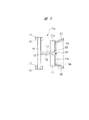
荷台昇降用梯子10aを後輪6に固定するために、図5に示されるように、支柱支持台11の背面側には、前側締結棒材27と後側締結棒材28とがそれぞれの基端部で取り付けられている。前側締結棒材27は、トラック1の前後方向に伸びる支柱支持台11の前端部に取り付けられており、後輪6の前側に突き当てられる。後側締結棒材28は、支柱支持台11の後端部に取り付けられており、後輪6の後側に突き当てられる。前側締結棒材27と後側締結棒材28は、先端部が広がるように傾斜している。つまり、前側締結棒材27は基端部よりも先端部がトラック1の前側となるように傾斜し、後側締結棒材28は基端部よりも先端部がトラック1の後側となるように傾斜している。   In order to fix the loading platform elevating ladder 10 a to the rear wheel 6, as shown in FIG. 5, the front side fastening bar 27 and the rear side fastening bar 28 are provided on the back side of the column support base 11. It is attached at the end. The front side fastening rod 27 is attached to the front end portion of the column support base 11 extending in the front-rear direction of the track 1 and abuts against the front side of the rear wheel 6. The rear fastening rod 28 is attached to the rear end portion of the support column support 11 and is abutted against the rear side of the rear wheel 6. The front side fastening bar 27 and the rear side fastening bar 28 are inclined so that the tip ends are widened. That is, the front fastening rod 27 is inclined so that the front end portion is on the front side of the track 1 with respect to the base end portion, and the rear fastening rod 28 is so arranged that the front end portion is on the rear side of the track 1 with respect to the base end portion. It is inclined to.

このように、前側締結棒材27と後側締結棒材28は先端部が広がるように傾斜しているので、支柱支持台11が車幅方向に移動されて後輪6に近付けられると、前側締結棒材27と後側締結棒材28は後輪6を挟み込むようにして後輪6に締結される。したがって、荷台昇降用梯子10aは、トラック1を移動させることなく、後輪6に接近移動させることにより、支柱支持台11の部分で容易に後輪6に締結することができる。しかも、図5において符号6a,6bで示されるように、径が相違する複数の後輪6a,6bに対しても、前側締結棒材27と後側締結棒材28を後輪6に締結することができる。後輪の径が相違すると、支柱支持台11の後輪6a,6bに対する接近距離は相違する。   Thus, since the front side fastening rod 27 and the rear side fastening rod 28 are inclined so that the front end portions are widened, the front support 11 is moved in the vehicle width direction and brought closer to the rear wheel 6, the front side The fastening rod 27 and the rear fastening rod 28 are fastened to the rear wheel 6 so as to sandwich the rear wheel 6. Therefore, the loading platform elevating ladder 10a can be easily fastened to the rear wheel 6 at the column support base 11 by moving the truck 1 closer to the rear wheel 6 without moving the truck 1. Moreover, as indicated by reference numerals 6 a and 6 b in FIG. 5, the front fastening rod 27 and the rear fastening rod 28 are fastened to the rear wheel 6 even for a plurality of rear wheels 6 a and 6 b having different diameters. be able to. When the diameters of the rear wheels are different, the approach distances to the rear wheels 6a and 6b of the column support base 11 are different.

荷台昇降用梯子10aをトラック1の側面に配置したときに、主支柱13または親綱支柱21がトラック1に直接当接することを防止するために、主支柱13には、突き当てパッド29が荷台昇降用梯子10aの背面側に突出して設けられている。突き当てパッド29は、主支柱13に装着されるクランプ部材30にねじ部材により取り付けられており、ねじ部材を回転させると、主支柱13から背面側への突き当てパッド29の突出量を調整擦ることができる。突き当てパッド29の先端部にはゴム等の弾性部材が設けられており、突き当てパッド29がトラック1に突き当てられても、トラック1の荷台3に傷が付くことが防止される。さらに、煽り板7が開放された状態で荷台3に対する荷物の積み卸し作業を行うときには、突き当てパッド29は煽り板7に突き当てられる。クランプ部材30は主支柱13に対して上下方向に移動すると、突き当てパッド29の上下方向位置を調整することができる。   In order to prevent the main column 13 or the main rope column 21 from coming into direct contact with the track 1 when the loading platform elevating ladder 10a is arranged on the side surface of the track 1, the abutment pad 29 is provided on the main column 13 with a loading platform. It protrudes from the back side of the elevating ladder 10a. The abutting pad 29 is attached to the clamp member 30 attached to the main support column 13 by a screw member. When the screw member is rotated, the protruding amount of the abutting pad 29 from the main support column 13 to the back side is adjusted and rubbed. be able to. An elastic member such as rubber is provided at the front end portion of the abutting pad 29, and even if the abutting pad 29 is abutted against the track 1, the cargo bed 3 of the track 1 is prevented from being damaged. Further, when carrying out the cargo loading / unloading operation with respect to the loading platform 3 in a state where the cover plate 7 is opened, the contact pad 29 is pressed against the cover plate 7. When the clamp member 30 moves in the vertical direction with respect to the main column 13, the vertical position of the abutting pad 29 can be adjusted.

荷台昇降用梯子10aをトラック1の側面に配置したときに、キャスター16に制動力を加えるために、キャスター支持金具17にはストッパ31が回動自在に装着されている。ストッパ31を作業者Pが足で回動操作させると、キャスター16の回転が規制される。   A stopper 31 is rotatably mounted on the caster support bracket 17 in order to apply a braking force to the caster 16 when the loading platform elevating ladder 10a is disposed on the side surface of the truck 1. When the operator P rotates the stopper 31 with his / her foot, the rotation of the caster 16 is restricted.

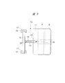
図6は、他の形態の荷台昇降用梯子10bを示す正面図である。図7は図6の右側面図であり、図8は図7の平面図である。   FIG. 6 is a front view showing a loading platform elevating ladder 10b of another form. 7 is a right side view of FIG. 6, and FIG. 8 is a plan view of FIG.

図6〜図8に示される荷台昇降用梯子10bにおいては、図8に示されるように、支柱支持台11はほぼ四角形の平板状の踏み板により形成されている。したがって、荷台昇降用梯子10bをトラック1の側面に配置するときには、地盤Bの所定の位置に支柱支持台11を位置決めする。この状態のもとで、荷物運搬車両であるトラック1を移動させて、支柱支持台11の上に後輪6を乗り上げる。これにより、支柱支持台11は後輪6と地盤Bとの間で締結される。   In the loading platform elevating ladder 10b shown in FIGS. 6 to 8, as shown in FIG. 8, the support column support 11 is formed of a substantially rectangular flat plate. Therefore, when the loading platform elevating ladder 10b is disposed on the side surface of the track 1, the support column support 11 is positioned at a predetermined position on the ground B. Under this state, the truck 1 which is a luggage transport vehicle is moved, and the rear wheel 6 is ridden on the support column support 11. Thereby, the support column 11 is fastened between the rear wheel 6 and the ground B.

このように、荷台昇降用梯子10bは、荷台昇降用梯子10aにおいては支柱支持台11に設けられた前側締結棒材27と後側締結棒材28とにより後輪6を挟み込んで後輪6に締結されるのに対して、支柱支持台11の上に後輪6を乗り上げることにより、支柱支持台11が締結される。支柱支持台11の構造を除いて、他の構造は荷台昇降用梯子10aと同様となっている。   In this way, the loading platform raising / lowering ladder 10b has the rear wheel 6 sandwiched between the front fastening rod 27 and the rear fastening rod 28 provided on the support column support 11 in the loading platform raising / lowering ladder 10a. On the other hand, the column support 11 is fastened by riding the rear wheel 6 on the column support 11. Except for the structure of the support column 11, the other structure is the same as the loading platform elevating ladder 10 a.

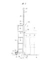
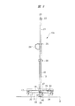
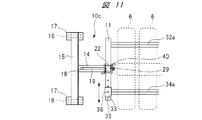
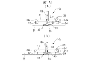
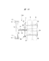
図9は、さらに他の形態の荷台昇降用梯子10cを示す正面図である。図10は図9の右側面図であり、図11は図10の平面図であり、図12(A)図10におけるA−A線断面図であり、図12(B)は支柱支持台と車輪との締結を解除した状態におけるA−A線断面図である。   FIG. 9 is a front view showing a loading platform elevating ladder 10c according to still another embodiment. 10 is a right side view of FIG. 9, FIG. 11 is a plan view of FIG. 10, FIG. 12 (A) is a cross-sectional view taken along the line AA in FIG. 10, and FIG. It is an AA line sectional view in the state where the conclusion with a wheel was canceled.

図9〜図12に示される荷台昇降用梯子10cにおいては、支柱支持台11は横断面が四角形の角パイプにより形成されている。角パイプからなる棒状の支柱支持台11は、主支柱13に対して車両前後に伸びており、支柱支持台11の長手方向中央部で主支柱13に直接取り付けられている。ただし、上述した荷台昇降用梯子10a,10bと同様に、主支柱13を支柱支持台11に固定された固定具12を介して主支柱13を支柱支持台11に取り付けるようにしても良い。   In the loading platform elevating ladder 10c shown in FIGS. 9 to 12, the support column support 11 is formed by a square pipe having a square cross section. A rod-like column support 11 made of a square pipe extends in the longitudinal direction of the vehicle with respect to the main column 13, and is directly attached to the main column 13 at the center in the longitudinal direction of the column support 11. However, similarly to the loading platform elevating ladders 10 a and 10 b described above, the main column 13 may be attached to the column support 11 via the fixture 12 that fixes the main column 13 to the column support 11.

支柱支持台11の一端部には、後輪6の前側に向けて突出する前側締結棒材32が取り付けられ、支柱支持台11の他端部には、スリーブ33が支柱支持台11に沿って図11において矢印で示されるように位置調整自在に装着されている。スリーブ33には後側締結棒材34が後輪6の後側に向けて突出して取り付けられている。前側締結棒材32と後側締結棒材34は、相互に平行となって支柱支持台11の下面に取り付けられ、荷台昇降用梯子10cの背面側に突出している。さらに、前側締結棒材32の背面側への突出部分の上面には、車止め部材32aが設けられ、後側締結棒材34の背面側への突出部分の上面には、車止め部材34aが設けられている。これにより、車止め部材32a,34aを含めた前側締結棒材32と後側締結棒材34の高さは高められている。それぞれの車止め部材32a,34aは、横断面が三角形となっており、上方に向けて突出している。ただし、それぞれの車止め部材32a,34aを前側締結棒材32と後側締結棒材34の上面に設けないようにしても良い。   A front side fastening bar 32 that protrudes toward the front side of the rear wheel 6 is attached to one end of the column support 11, and a sleeve 33 extends along the column support 11 at the other end of the column support 11. As shown by the arrow in FIG. 11, it is mounted so that its position can be adjusted. A rear fastening rod 34 is attached to the sleeve 33 so as to protrude toward the rear side of the rear wheel 6. The front side fastening bar 32 and the rear side fastening bar 34 are attached to the lower surface of the column support base 11 in parallel with each other, and project to the back side of the loading platform elevating ladder 10c. Further, a car stopper member 32a is provided on the upper surface of the protruding portion of the front side fastening bar 32 toward the back surface, and a car stopper member 34a is provided on the upper surface of the portion of the rear side fastening bar 34 protruding toward the back surface. ing. Thereby, the height of the front side fastening bar 32 and the rear side fastening bar 34 including the car stopper members 32a and 34a is increased. Each of the vehicle stop members 32a and 34a has a triangular cross section and protrudes upward. However, the vehicle stopper members 32 a and 34 a may not be provided on the upper surfaces of the front side fastening bar 32 and the rear side fastening bar 34.

図11に示されるように、支柱支持台11には所定の間隔を置いて複数の取付孔35が設けられ、スリーブ33には位置決めピン36が取り付けられる。スリーブ33を支柱支持台11に対して所定の位置に位置決めした状態のもとで、位置決めピン36をスリーブ33に設けられた貫通孔を貫通させて取付孔35に取り付けると、スリーブ33は支柱支持台11に固定される。   As shown in FIG. 11, the support column 11 is provided with a plurality of attachment holes 35 at predetermined intervals, and the positioning pins 36 are attached to the sleeve 33. When the sleeve 33 is positioned at a predetermined position with respect to the support column 11 and the positioning pin 36 is attached to the mounting hole 35 through the through-hole provided in the sleeve 33, the sleeve 33 is supported by the support column. Fixed to the base 11.

前側締結棒材32と後側締結棒材34の支柱支持台11の前後方向の間隔は、予め、スリーブ33を調整移動することにより、後輪6が地盤Bに接触している部分よりも長い距離に設定され、後輪6の直径よりも短い距離に設定されている。したがって、荷台昇降用梯子10cをトラック1に接近させると、前側締結棒材32は後輪6の前側の部分のうち地盤Bに対向した後輪6の下側の円弧面の部分に隙間を介して突出し、後側締結棒材34は後輪6の後側の部分のうち地盤Bに対向した後輪6の下側の円弧面の部分に隙間を介して突出する。   The distance between the front fastening bar 32 and the rear fastening bar 34 in the front-rear direction of the support column 11 is longer than the part where the rear wheel 6 is in contact with the ground B by adjusting and moving the sleeve 33 in advance. The distance is set to be shorter than the diameter of the rear wheel 6. Therefore, when the loading platform elevating ladder 10c is brought close to the track 1, the front fastening bar 32 is interposed through a gap in the portion of the front side of the rear wheel 6 on the lower circular surface of the rear wheel 6 facing the ground B. The rear fastening bar 34 projects through a gap to a portion of the lower circular arc surface of the rear wheel 6 facing the ground B in the rear portion of the rear wheel 6.

前側締結棒材32と後側締結棒材34を後輪6に押し付けて、支柱支持台11を前側締結棒材32と後側締結棒材34を介して後輪6に締結するために、支柱支持台11の長手方向中央部には、上下動ジャッキ37が設けられている。上下動ジャッキ37は、支柱支持台11にねじ結合される雄ねじ部材38と、この下端部に取り付けられた押圧プレート39とを有し、雄ねじ部材38にはこれを回転操作する操作ハンドル40が設けられている。したがって、操作ハンドル40を回転操作して雄ねじ部材38を回転させると、押圧プレート39が下方に突出して地盤Bに接触する。さらに、操作ハンドル40を回転させると、下方に突出する押圧プレート39により、図10および図12(A)に示されるように、荷台昇降用梯子10cは持ち上げられて、前側締結棒材32と後側締結棒材34が後輪6に締結される。これにより、前側締結棒材32と後側締結棒材34の上昇移動により支柱支持台11は後輪6に締結される。   In order to press the front fastening bar 32 and the rear fastening bar 34 against the rear wheel 6 and fasten the support column 11 to the rear wheel 6 via the front fastening bar 32 and the rear fastening bar 34, A vertical movement jack 37 is provided at the longitudinal center of the support base 11. The vertical movement jack 37 has a male screw member 38 screwed to the support column 11 and a pressing plate 39 attached to the lower end portion. The male screw member 38 is provided with an operation handle 40 for rotating the male screw member 38. It has been. Therefore, when the operating handle 40 is rotated to rotate the male screw member 38, the pressing plate 39 protrudes downward and contacts the ground B. Further, when the operation handle 40 is rotated, the loading platform elevating ladder 10c is lifted by the pressing plate 39 protruding downward, as shown in FIGS. 10 and 12, and the front fastening bar 32 and the rear The side fastening bar 34 is fastened to the rear wheel 6. As a result, the support column 11 is fastened to the rear wheel 6 by the upward movement of the front fastening bar 32 and the rear fastening bar 34.

上下動ジャッキ37を操作して、図12(B)に示されるように、押圧プレート39を上昇させると、前側締結棒材32と後側締結棒材34が地盤Bに接触する。この状態のもとでは、キャスター16も地盤Bに接触する。したがって、この状態のもとで、荷台昇降用梯子10cを傾斜させると、作業者Pは容易に荷台昇降用梯子10cを任意の位置に移動させることができる。これにより、荷物の積み卸しを行う作業場の片隅に保管された荷台昇降用梯子10cを、トラック1の側面にまで容易に搬送することができる。荷台昇降用梯子10cをトラック1の側面まで移動した状態のもとで、上下動ジャッキ37により支柱支持台11を上昇させると、支柱支持台11は後輪6に締結される。支柱支持台11の構造を除いて、他の構造は荷台昇降用梯子10a,10bと同様となっている。   When the vertical movement jack 37 is operated to raise the pressing plate 39 as shown in FIG. 12B, the front side fastening bar 32 and the rear side fastening bar 34 come into contact with the ground B. Under this state, the caster 16 also contacts the ground B. Therefore, when the loading platform elevating ladder 10c is tilted under this state, the worker P can easily move the loading platform elevating ladder 10c to an arbitrary position. Thereby, the loading platform elevating ladder 10c stored in one corner of the work place where the cargo is loaded and unloaded can be easily conveyed to the side surface of the truck 1. Under the state where the loading platform elevating ladder 10 c is moved to the side surface of the truck 1, when the column support table 11 is raised by the vertical movement jack 37, the column support table 11 is fastened to the rear wheel 6. Except for the structure of the support column 11, other structures are the same as the loading platform elevating ladders 10 a and 10 b.

図13は、さらに他の形態の荷台昇降用梯子10dを示す正面図である。図14は図13の右側面図であり、図15は図14の平面図である。   FIG. 13 is a front view showing a loading platform elevating ladder 10d according to still another embodiment. 14 is a right side view of FIG. 13, and FIG. 15 is a plan view of FIG.

この荷台昇降用梯子10dの支柱支持台11は、角パイプからなる前側摺動部材41と、この外側に摺動自在に嵌合される角パイプからなる後側摺動部材42とを備えている。後側摺動部材42には、主支柱13が固定される固定具12が取り付けられており、前側摺動部材41と後側摺動部材42はそれぞれトラック1の前後方向に伸びている。   The column support base 11 of the loading platform elevating ladder 10d includes a front sliding member 41 made of a square pipe and a rear sliding member 42 made of a square pipe that is slidably fitted to the outside. . A fixing tool 12 to which the main column 13 is fixed is attached to the rear sliding member 42, and the front sliding member 41 and the rear sliding member 42 extend in the front-rear direction of the track 1.

前側摺動部材41の下面には、図13〜図15に示されるように、後輪6の前側に向けて突出する前側締結棒材43が設けられ、後側摺動部材42の下面には後輪6の後側に向けて突出する後側締結棒材44が設けられている。前側締結棒材43と後側締結棒材44は、相互に平行となっている。前側摺動部材41は後側摺動部材42に摺動自在に嵌合され、前側摺動部材41と後側摺動部材42は相互に相対的に長手方向に摺動自在となっており、前側摺動部材41を後側摺動部材42に対して摺動させると、前側締結棒材43と後側締結棒材44の間の距離が変化する。   As shown in FIGS. 13 to 15, a front fastening rod 43 that protrudes toward the front side of the rear wheel 6 is provided on the lower surface of the front sliding member 41. A rear side fastening bar 44 that protrudes toward the rear side of the rear wheel 6 is provided. The front side fastening bar 43 and the rear side fastening bar 44 are parallel to each other. The front sliding member 41 is slidably fitted to the rear sliding member 42, and the front sliding member 41 and the rear sliding member 42 are slidable relative to each other in the longitudinal direction. When the front sliding member 41 is slid with respect to the rear sliding member 42, the distance between the front fastening bar 43 and the rear fastening bar 44 changes.

前側摺動部材41と後側摺動部材42とを相対的に軸方向に駆動する水平動ジャッキ45が支柱支持台11に設けられている。水平動ジャッキ45は、前側摺動部材41の端部に取り付けられる雄ねじ部材46を有し、雄ねじ部材46は後側摺動部材42の端部から突出している。雄ねじ部材46には操作ハンドル47がねじ結合されるとともに、操作ハンドル47は後側摺動部材42の端面に回転自在に装着される。操作ハンドル47を回転させて、前側摺動部材41と後側摺動部材42とを相対的に軸方向に駆動すると、前側締結棒材43と後側締結棒材44とが相対的に接近離反移動する。   A horizontal movement jack 45 that relatively drives the front sliding member 41 and the rear sliding member 42 in the axial direction is provided on the support column support 11. The horizontal jack 45 has a male screw member 46 attached to the end of the front sliding member 41, and the male screw member 46 projects from the end of the rear sliding member 42. An operation handle 47 is screwed to the male screw member 46, and the operation handle 47 is rotatably mounted on the end surface of the rear sliding member 42. When the operation handle 47 is rotated and the front sliding member 41 and the rear sliding member 42 are driven relatively in the axial direction, the front fastening bar 43 and the rear fastening bar 44 are relatively close to each other. Moving.

したがって、前側締結棒材43と後側締結棒材44の前後方向の間隔が、後輪6が地盤Bに接触している部分よりも長い距離となるように、前側摺動部材41を後側摺動部材42に対して摺動させた状態のもとで、荷台昇降用梯子10dをトラック1に接近させると、前側締結棒材43は後輪6の前側の部分のうち地盤Bに対向した後輪6の下側の円弧面の部分に隙間を介して突出し、後側締結棒材44は後輪6の後側の部分のうち地盤Bに対向した後輪6の下側の円弧面の部分に隙間を介して突出する。この状態のもとで、操作ハンドル47を操作して前側締結棒材43と後側締結棒材44の間隔を小さくしてこれらを接近させると、支柱支持台11は、前側締結棒材43と後側締結棒材44の接近移動により後輪6に締結される。支柱支持台11の構造を除いて、他の構造は荷台昇降用梯子10a,10b,10cと同様となっている。   Therefore, the front sliding member 41 is arranged on the rear side so that the distance in the front-rear direction between the front fastening bar 43 and the rear fastening bar 44 is longer than the part where the rear wheel 6 is in contact with the ground B. When the loading platform elevating ladder 10d is brought close to the track 1 under the state of sliding with respect to the sliding member 42, the front fastening rod 43 faces the ground B in the front portion of the rear wheel 6. The rear wheel 6 protrudes through a gap on the lower arc surface portion of the rear wheel 6, and the rear fastening rod 44 is formed on the lower arc surface of the rear wheel 6 facing the ground B in the rear portion of the rear wheel 6. It protrudes through a gap in the part. Under this state, when the operation handle 47 is operated to reduce the distance between the front side fastening bar 43 and the rear side fastening bar 44 and bring them closer to each other, the support column 11 is connected to the front side fastening bar 43. The rear side fastening rod 44 is fastened to the rear wheel 6 by the approaching movement. Except for the structure of the support column 11, the other structure is the same as the loading platform elevating ladders 10 a, 10 b, and 10 c.

上述した荷台昇降用梯子10c,10dにおいては、荷台昇降用梯子10aと同様に、トラック1を移動させることなく、荷台昇降用梯子10c,10dを後輪6に接近させて、上下動ジャッキ37や水平動ジャッキ45を駆動することにより、支柱支持台11を後輪6に締結することができる。これにより、支柱支持台11の後輪6に対する締結作業を容易に行うことができる。しかも、それぞれの荷台昇降用梯子10a〜10dは、親綱Wの張り渡し作業と、作業者Pの荷台3への上り下り作業とを行うことができるので、荷物の積み込みと積み卸し作業の作業性を向上させることができる。荷台3への上り下りのときには、作業者Pは車幅方向の踏み材19と荷台3との間を容易に乗り移ることができる。   In the loading platform raising / lowering ladders 10c and 10d, the loading platform raising / lowering ladders 10c and 10d are brought close to the rear wheel 6 without moving the truck 1 in the same manner as the loading platform raising / lowering ladder 10a. The support column 11 can be fastened to the rear wheel 6 by driving the horizontal moving jack 45. Thereby, the fastening operation | work with respect to the rear wheel 6 of the support | pillar support stand 11 can be performed easily. Moreover, each of the platform lifting ladders 10a to 10d can perform the work of transferring the master rope W and the work of ascending / descending the worker P to the platform 3, so that the loading and unloading operations of the luggage can be performed. Can be improved. When going up and down to the loading platform 3, the worker P can easily transfer between the foot material 19 in the vehicle width direction and the loading platform 3.

それぞれの荷台昇降用梯子10a〜10dにおいては、踏み材19の一端部が梯子支柱18に固定され、他端部が主支柱13に直接固定されているが、踏み材19の他端部に図示しない他の補助支柱に固定するようしても良い。その場合には、梯子支柱18と補助支柱との間に踏み材19が固定され、補助支柱が主支柱13に固定された形態となる。それぞれの荷台昇降用梯子10a〜10dには、キャスター16が設けられており、キャスター16により、容易に荷台昇降用梯子を移動させることができるようになっているが、キャスター16を設けない形態としても、上述した荷物の積み込みと積み卸し作業を行うことができる。   In each of the loading platform raising / lowering ladders 10a to 10d, one end portion of the tread 19 is fixed to the ladder support 18 and the other end is directly fixed to the main support 13. You may make it fix to other auxiliary struts which do not. In that case, the tread 19 is fixed between the ladder column 18 and the auxiliary column, and the auxiliary column is fixed to the main column 13. Each of the loading platform raising / lowering ladders 10a to 10d is provided with a caster 16 so that the loading platform raising / lowering ladder can be easily moved by the caster 16, but the caster 16 is not provided. Also, the above-described loading and unloading operations can be performed.

本発明は前記実施の形態に限定されるものではなく、その要旨を逸脱しない範囲で種々変更可能である。例えば、上述した荷台昇降用梯子10a〜10dは、後輪6に締結する場合について示すが、前輪4や後輪5にも締結することができる。このように、いずれの車輪に対しても荷台昇降用梯子10a〜10dを締結することができる。また、荷台3への荷物の積み卸し作業は、トラック1のみならず、トレーラ等のように、荷台を備えた荷物運搬車両に対してそれぞれの荷台昇降用梯子を使用することができる。   The present invention is not limited to the above-described embodiment, and various modifications can be made without departing from the scope of the invention. For example, although the loading platform elevating ladders 10a to 10d described above are shown as being fastened to the rear wheel 6, they can also be fastened to the front wheel 4 and the rear wheel 5. Thus, the platform lifting ladders 10a to 10d can be fastened to any wheel. In addition, the loading / unloading operation of the cargo on the loading platform 3 can use each loading platform elevating ladder not only for the truck 1 but also for a cargo transportation vehicle including the loading platform such as a trailer.

1 トラック(荷物運搬車両)
3 荷台
7 煽り板
10a〜10d 荷台昇降用梯子
11 支柱支持台
12 固定具
13 主支柱
14 支持具
15 脚部
16 キャスター
18 梯子支柱
19 踏み材
21 親綱支柱
22 綱掛け部
27 前側締結棒材
28 後側締結棒材
29 突き当てパッド
30 クランプ部材
31 ストッパ
32 前側締結棒材
33 スリーブ
34 後側締結棒材
35 取付孔
36 位置決めピン
37 上下動ジャッキ
38 雄ねじ部材
39 押圧プレート
40 操作ハンドル
41 前側摺動部材
42 後側摺動部材
43 前側締結棒材
44 後側締結棒材
45 水平動ジャッキ
46 雄ねじ部材
47 操作ハンドル
1 Truck (Luggage carrier)
3 Loading platform 7 Lifting plates 10a to 10d Loading platform raising / lowering ladder 11 Support column support 12 Fixing tool 13 Main support column 14 Supporting tool 15 Leg 16 Caster 18 Ladder column 19 Tread 21 Parent rope support 22 Tight rail 27 Front fastening rod 28 Rear side fastening bar 29 Abutting pad 30 Clamp member 31 Stopper 32 Front side fastening bar 33 Sleeve 34 Rear side fastening bar 35 Mounting hole 36 Positioning pin 37 Vertical movement jack 38 Male screw member 39 Press plate 40 Operation handle 41 Front side sliding Member 42 Rear side sliding member 43 Front side fastening bar 44 Rear side fastening bar 45 Horizontal moving jack 46 Male screw member 47 Operation handle

Claims (5)

主支柱が取り付けられ、荷物運搬車両の車輪に締結される支柱支持台と、
前記車輪に対して前記主支柱を介して反対側に突出して前記主支柱に取り付けられる支持具と、
前記支持具に取り付けられ、前記主支柱に沿って伸びる梯子支柱と、
前記主支柱と前記梯子支柱との間に、前記荷物運搬車両の車幅方向に伸びて設けられる複数の踏み材と、
前記荷物運搬車両の荷台の上方に張り渡される親綱が掛けられる綱掛け部を備え、前記主支柱に軸方向に摺動自在に装着される親綱支柱と、
前記支持具の先端に前記荷物運搬車両の側面に沿う方向に延びて取り付けられる脚部と、
前記脚部の両端部に設けられるキャスターと、を有し、
前記キャスターのみが地面に接触するように傾斜させ、前記キャスターにより移動させることができる、荷台昇降用梯子。
A column support to which the main column is attached and fastened to the wheel of the luggage carrier vehicle;
A support that protrudes to the opposite side of the wheel via the main column and is attached to the main column;
A ladder column attached to the support and extending along the main column;
A plurality of footsteps provided between the main column and the ladder column and extending in the vehicle width direction of the luggage carrier vehicle;
A main rope support that is provided with a leash rack portion on which a main rope stretched above the loading platform of the luggage carrier vehicle is hung, and is slidably mounted in the axial direction on the main strut;
A leg portion extending and attached to the tip of the support tool in a direction along the side surface of the luggage carrier vehicle;
Have a, and casters provided at both ends of said legs,
A loading platform raising / lowering ladder that is inclined so that only the casters come into contact with the ground and can be moved by the casters .
請求項1記載の荷台昇降用梯子において、前記車輪の前側に向けて突出し前記車輪の前側に突き当てられる前側締結棒材と、前記車輪の後側に向けて突出し前記車輪の後側に突き当てられる後側締結棒材とが前記支柱支持台に設けられ、前記前側締結棒材と前記後側締結棒材は先端部が広がるように傾斜し、前記支柱支持台が前記車輪に近付けられると前記前側締結棒材と前記後側締結棒材は前記車輪を挟み込んで前記車輪に締結される、荷台昇降用梯子。   The ladder for raising and lowering the cargo bed according to claim 1, wherein the front fastening bar protrudes toward the front side of the wheel and abuts against the front side of the wheel, and projects toward the rear side of the wheel and abuts against the rear side of the wheel. And a rear fastening rod is provided on the support column, and the front fastening rod and the rear fastening rod are inclined so that a front end portion spreads, and when the support column is brought close to the wheel, The loading platform elevating ladder, wherein the front fastening rod and the rear fastening rod are fastened to the wheel with the wheel interposed therebetween. 請求項1記載の荷台昇降用梯子において、前記支柱支持台は、前記車輪が乗り上げる踏み板を有し、前記車輪と地盤との間で前記支柱支持台が締結される、荷台昇降用梯子。   The ladder for raising / lowering the loading platform according to claim 1, wherein the column support platform includes a tread plate on which the wheel rides, and the column support platform is fastened between the wheel and the ground. 請求項1記載の荷台昇降用梯子において、前記支柱支持台は、前記車輪の前側に向けて突出する前側締結棒材と、前記車輪の後側に向けて前記前側締結棒材と平行となって突出する後側締結棒材と、前記前側締結棒材および前記後側締結棒材を上下方向に駆動する上下動ジャッキとを有し、前記支柱支持台は前記前側締結棒材および前記後側締結棒材の上昇移動により前記車輪に締結される、荷台昇降用梯子。   The ladder for raising and lowering the cargo bed according to claim 1, wherein the support column is parallel to the front fastening bar that protrudes toward the front side of the wheel and the front fastening bar toward the rear side of the wheel. A rear fastening rod that protrudes, and a vertical movement jack that drives the front fastening rod and the rear fastening rod in a vertical direction, and the column support base includes the front fastening rod and the rear fastening. A loading platform raising / lowering ladder fastened to the wheel by the upward movement of the bar. 請求項1記載の荷台昇降用梯子において、前記支柱支持台は、前記車輪の前側に向けて突出する前側締結棒材が設けられ荷物運搬車両の前後方向に伸びる前側摺動部材と、前記車輪の後側に向けて突出する後側締結棒材が設けられ前記前側摺動部材に対して相対的に軸方向に摺動自在に装着される後側摺動部材と、前記前側摺動部材と前記後側摺動部材とを相対的に軸方向に駆動し、前記前側締結棒材と前記後側締結棒材を相対的に接近離反移動する水平動ジャッキとを有し、前記支柱支持台は前記前側締結棒材および前記後側締結棒材の接近移動により前記車輪に締結される、荷台昇降用梯子。   The ladder for raising and lowering the cargo bed according to claim 1, wherein the column support base is provided with a front side sliding member that protrudes toward the front side of the wheel and extends in the front-rear direction of the load carrying vehicle; A rear side sliding member that protrudes toward the rear side is provided and is slidably mounted in the axial direction relative to the front side sliding member; the front side sliding member; A horizontal sliding jack that relatively axially drives a rear sliding member and moves the front fastening bar and the rear fastening bar relatively closer to and away from each other; A ladder for raising and lowering a cargo bed that is fastened to the wheel by an approaching movement of a front side fastening bar and the rear side fastening bar.
JP2015199055A 2015-10-07 2015-10-07 Cargo lift ladder Active JP6605906B2 (en)

Priority Applications (1)

Application Number Priority Date Filing Date Title
JP2015199055A JP6605906B2 (en) 2015-10-07 2015-10-07 Cargo lift ladder

Applications Claiming Priority (1)

Application Number Priority Date Filing Date Title
JP2015199055A JP6605906B2 (en) 2015-10-07 2015-10-07 Cargo lift ladder

Publications (2)

Publication Number Publication Date
JP2017071951A JP2017071951A (en) 2017-04-13
JP6605906B2 true JP6605906B2 (en) 2019-11-13

Family

ID=58539253

Family Applications (1)

Application Number Title Priority Date Filing Date
JP2015199055A Active JP6605906B2 (en) 2015-10-07 2015-10-07 Cargo lift ladder

Country Status (1)

Country Link
JP (1) JP6605906B2 (en)

Cited By (1)

* Cited by examiner, † Cited by third party
Publication number Priority date Publication date Assignee Title
FR3108135A1 (en) * 2020-03-11 2021-09-17 Nexter Systems SAFETY DEVICE TO ALLOW WORK AT HEIGHT ON A VEHICLE

Families Citing this family (2)

* Cited by examiner, † Cited by third party
Publication number Priority date Publication date Assignee Title
JP7349093B2 (en) * 2019-11-28 2023-09-22 セイコー機器株式会社 Main rope support
JP7386491B1 (en) 2023-09-29 2023-11-27 日本特殊車輌サービス株式会社 truck bed ladder

Family Cites Families (7)

* Cited by examiner, † Cited by third party
Publication number Priority date Publication date Assignee Title
JP3285840B2 (en) * 1999-04-05 2002-05-27 飛島建設株式会社 Safety belt mounting device
JP3385465B2 (en) * 2000-02-23 2003-03-10 弘毅 火ノ口 Unauthorized parking vehicle movement prevention device
JP2006320693A (en) * 2005-05-20 2006-11-30 Takahiro Kasahara Injury reducing device against falling accident of worker
JP2010220916A (en) * 2009-03-25 2010-10-07 Sanki Eng Co Ltd Supporter for stretching main rope, and main rope stretching device
US8616332B2 (en) * 2010-03-22 2013-12-31 Ihi E&C International Corporation Portable vehicle-stabilized mast and fall protection system
JP5608106B2 (en) * 2011-01-14 2014-10-15 鹿島建設株式会社 Cargo bed fall prevention fence combined wheel stop
US9663990B2 (en) * 2014-03-04 2017-05-30 Mark Allen Kramer Ladder assist

Cited By (1)

* Cited by examiner, † Cited by third party
Publication number Priority date Publication date Assignee Title
FR3108135A1 (en) * 2020-03-11 2021-09-17 Nexter Systems SAFETY DEVICE TO ALLOW WORK AT HEIGHT ON A VEHICLE

Also Published As

Publication number Publication date
JP2017071951A (en) 2017-04-13

Similar Documents

Publication Publication Date Title
US4258826A (en) Combination stepladder and load lifting apparatus
CN108033392B (en) A kind of movable type goods and materials handling assistance platform
JP6605906B2 (en) Cargo lift ladder
US4752173A (en) Hand truck apparatus for lifting as well as transporting loads, such as solid core doors, and method of installing a door
JP4556136B2 (en) Fall prevention tool and its use, and fall prevention fence and its use
WO2010128340A2 (en) Fall prevention system and access ladder
JP2017501096A (en) Lowrider wheel jack
DE60305008D1 (en) LIFTING EQUIPMENT AND BAG CARRIER
KR101035606B1 (en) handcart work trap
JP2017039401A (en) Truck for easy loading/unloading of cargo in vehicle or the like
JP6234831B2 (en) Carriage cart with lifting roller
KR100693138B1 (en) Apparatus for supporting body of electric rail car
KR20080069282A (en) Handcart work trap
KR100831849B1 (en) Fork handcart
JP4587379B2 (en) Transporter
US2234255A (en) Load transfer apparatus
US20060055134A1 (en) Hand cart
US20190308861A1 (en) Countertop Installation Cart
JP3225691U (en) Ladder supporting ladder
KR101824323B1 (en) Moving cart capable of getting on and off for steps
CN106004636B (en) Vehicle-mounted general cylindricality equipment fixing device
JP2013245469A (en) Cargo handling platform
JP6587876B2 (en) Handling equipment
JP2019026063A (en) Lifting assist tool for dolly with stair lifting function
JP7453095B2 (en) Lifting steps and loading platform unit

Legal Events

Date Code Title Description
A621 Written request for application examination

Free format text: JAPANESE INTERMEDIATE CODE: A621

Effective date: 20180828

A131 Notification of reasons for refusal

Free format text: JAPANESE INTERMEDIATE CODE: A131

Effective date: 20190409

A977 Report on retrieval

Free format text: JAPANESE INTERMEDIATE CODE: A971007

Effective date: 20190410

A521 Request for written amendment filed

Free format text: JAPANESE INTERMEDIATE CODE: A523

Effective date: 20190523

TRDD Decision of grant or rejection written
A01 Written decision to grant a patent or to grant a registration (utility model)

Free format text: JAPANESE INTERMEDIATE CODE: A01

Effective date: 20191015

A61 First payment of annual fees (during grant procedure)

Free format text: JAPANESE INTERMEDIATE CODE: A61

Effective date: 20191017

R150 Certificate of patent or registration of utility model

Ref document number: 6605906

Country of ref document: JP

Free format text: JAPANESE INTERMEDIATE CODE: R150

R250 Receipt of annual fees

Free format text: JAPANESE INTERMEDIATE CODE: R250

R250 Receipt of annual fees

Free format text: JAPANESE INTERMEDIATE CODE: R250