JP6603574B2 - Air-cooled heat exchange unit, unit heat exchanger and cooler unit - Google Patents
Air-cooled heat exchange unit, unit heat exchanger and cooler unit Download PDFInfo
- Publication number
- JP6603574B2 JP6603574B2 JP2015251388A JP2015251388A JP6603574B2 JP 6603574 B2 JP6603574 B2 JP 6603574B2 JP 2015251388 A JP2015251388 A JP 2015251388A JP 2015251388 A JP2015251388 A JP 2015251388A JP 6603574 B2 JP6603574 B2 JP 6603574B2
- Authority
- JP
- Japan
- Prior art keywords
- heat exchange
- air
- heat exchanger
- unit
- header pipe
- Prior art date
- Legal status (The legal status is an assumption and is not a legal conclusion. Google has not performed a legal analysis and makes no representation as to the accuracy of the status listed.)
- Active
Links
Images


Classifications
-
- Y—GENERAL TAGGING OF NEW TECHNOLOGICAL DEVELOPMENTS; GENERAL TAGGING OF CROSS-SECTIONAL TECHNOLOGIES SPANNING OVER SEVERAL SECTIONS OF THE IPC; TECHNICAL SUBJECTS COVERED BY FORMER USPC CROSS-REFERENCE ART COLLECTIONS [XRACs] AND DIGESTS
- Y02—TECHNOLOGIES OR APPLICATIONS FOR MITIGATION OR ADAPTATION AGAINST CLIMATE CHANGE
- Y02B—CLIMATE CHANGE MITIGATION TECHNOLOGIES RELATED TO BUILDINGS, e.g. HOUSING, HOUSE APPLIANCES OR RELATED END-USER APPLICATIONS
- Y02B30/00—Energy efficient heating, ventilation or air conditioning [HVAC]
Description
本開示は、空冷式熱交換ユニット及びこの空冷式熱交換ユニットを備えたユニット型熱交換器及びクーラユニットに関する。 The present disclosure relates to an air-cooled heat exchange unit and a unit heat exchanger and a cooler unit including the air-cooled heat exchange unit.
建物の空調や給湯を行うユニット型の冷凍機器や給湯機器が知られている(例えば特許文献1)。
上記装置において、冷凍サイクルやヒートポンプサイクルを構成する機器の一部として凝縮器が用いられる。凝縮器には空冷式及び水冷式があるが、空冷式凝縮器の場合、従来の機器では、空気取込み開口に面して伝熱部が配置されるのが一般的である。しかし、ユニット型の機器では、空気取込み開口の大きさに制約があるため、伝熱面の面積は制約を受ける。
そこで、特許文献2には、伝熱面積を増加させるために、ユニット本体の外形をV字形にし、外表面に面してV字形の熱交換器を配置した熱交換ユニットが開示されている。この熱交換ユニットは、複数の熱交換ユニットを並べて配置することで、伝熱面の面積を確保するものであり、熱交換器をV字形を形成することで、複数の熱交換ユニットを並べて配置しても熱交換面に至る空気流路の形成を可能にしている。
There are known unit-type refrigeration equipment and hot water supply equipment for air conditioning and hot water supply of buildings (for example, Patent Document 1).
In the above apparatus, a condenser is used as a part of equipment constituting a refrigeration cycle or a heat pump cycle. There are air-cooled and water-cooled condensers, but in the case of air-cooled condensers, in conventional equipment, the heat transfer section is generally arranged facing the air intake opening. However, in the unit type equipment, the size of the air intake opening is limited, so the area of the heat transfer surface is limited.
Therefore, Patent Document 2 discloses a heat exchange unit in which the outer shape of the unit body is V-shaped and a V-shaped heat exchanger is arranged facing the outer surface in order to increase the heat transfer area. This heat exchange unit secures the area of the heat transfer surface by arranging a plurality of heat exchange units side by side, and arranging a plurality of heat exchange units side by side by forming a V-shaped heat exchanger. Even so, it is possible to form an air flow path leading to the heat exchange surface.
特許文献1及び2に開示されたユニット型の冷凍機器や給湯機器は、熱交換器の熱交換面をユニット本体の外表面に沿って配置しているため、伝熱面積の確保に限界がある。
また、伝熱面が外表面に面しているため、飛石などによって傷が付きやすく、傷付きによる腐食が進行しやすいという問題がある。
The unit-type refrigeration equipment and hot water supply equipment disclosed in Patent Documents 1 and 2 have a limit in securing a heat transfer area because the heat exchange surface of the heat exchanger is arranged along the outer surface of the unit body. .
In addition, since the heat transfer surface faces the outer surface, there is a problem that scratches are easily caused by flying stones, and corrosion due to scratches is likely to proceed.
本発明の少なくとも一実施形態は、上記課題に鑑み、ユニット型の空調機器、給湯機器及び冷凍機器等に適用される熱交換器において、熱交換面の面積確保を可能とし、かつ熱交換器の腐食の進行を抑制すると共に、コンパクト化を達成することを目的とする。 In view of the above problems, at least one embodiment of the present invention is capable of ensuring the area of a heat exchange surface in a heat exchanger applied to a unit type air conditioner, a hot water supply device, a refrigeration device, and the like. The object is to suppress the progress of corrosion and achieve compactness.
(1)本発明の少なくとも一実施形態に係る空冷式熱交換ユニットは、
縦面を形成する仕切り板、前面を斜め下向きに配置された板状の熱交換器及び側面パネルによって逆三角形断面の内側空間を形成する複数の熱交換パネルと、
前記複数の熱交換パネルの前記仕切り板の両側面部下端が結合されることで、前記複数の熱交換パネルを前記側面パネルが一方向に沿って並ぶように並列に配置するための一対の支持フレームと、
前記複数の熱交換パネルの前記仕切り板の上端が、隣接配置された前記熱交換パネルの前記仕切り板の上端に結合される第1の結合部と、
を備える。
(1) An air-cooled heat exchange unit according to at least one embodiment of the present invention includes:
A plurality of heat exchange panels forming an inner space of an inverted triangular cross section by a partition plate that forms a vertical surface, a plate-like heat exchanger whose front surface is arranged obliquely downward, and a side panel;
A pair of support frames for arranging the plurality of heat exchange panels in parallel so that the side panels are aligned along one direction by joining lower ends of both side surfaces of the partition plates of the plurality of heat exchange panels. When,
A first coupling portion in which upper ends of the partition plates of the plurality of heat exchange panels are coupled to upper ends of the partition plates of the heat exchange panels disposed adjacent to each other;
Is provided.
上記構成(1)では、複数の熱交換パネルは、上記一対の支持フレームに結合されて、側面パネルが一方向に沿って並ぶように並列に配置される。
かかる配置としても、熱交換ユニットは逆三角形断面を形成するため、熱交換器の前面(空気が流入する側の面)に空気流入空間を形成できるため、熱交換器を通る空気流量を確保でき、伝熱効果を得ることができる。
また、複数の熱交換パネルが並列に配置されるため、熱交換器の熱交換面を増加でき、伝熱効果を向上できると共に、熱交換器は、ユニット本体の内部で空気の流入が可能な側面に対して交差する方向に配置されるため、ユニット本体の容積を増加させることなく、熱交換面積を確保できる。これによって、ユニット本体をコンパクト化できる。
また、かかる構成の熱交換ユニットを冷凍機器などのユニット本体の内部に配置した場合、従来のように、熱交換面が空気取込み開口に面して配置されない。そのため、飛来する飛石などの障害物が熱交換器に当たる可能性は、従来と比べて大幅に低減し、これによって、飛石などによる熱交換器の傷の発生を抑制できると共に、傷の発生に起因した腐食の進行を抑制できる。
また、複数の熱交換パネルを一対の支持フレームで固定するため、熱交換ユニットをコンパクト化できる。
In the configuration (1), the plurality of heat exchange panels are coupled to the pair of support frames, and are arranged in parallel so that the side panels are aligned along one direction.
Even in such an arrangement, the heat exchange unit forms an inverted triangular cross section, so that an air inflow space can be formed on the front surface of the heat exchanger (the surface on the air inflow side), so that the air flow rate through the heat exchanger can be secured. , Heat transfer effect can be obtained.
In addition, since a plurality of heat exchange panels are arranged in parallel, the heat exchange surface of the heat exchanger can be increased, the heat transfer effect can be improved, and the heat exchanger can allow air to flow inside the unit body. Since it arrange | positions in the direction which cross | intersects with respect to a side surface, a heat exchange area is securable without increasing the volume of a unit main body. Thereby, the unit main body can be made compact.
Further, when the heat exchange unit having such a configuration is arranged inside a unit main body such as a refrigeration apparatus, the heat exchange surface is not arranged facing the air intake opening as in the related art. Therefore, the possibility that the flying stones and other obstacles will hit the heat exchanger is greatly reduced compared to the conventional case, which can suppress the occurrence of scratches on the heat exchanger due to flying stones and the like. It is possible to suppress the progress of corrosion.
Further, since the plurality of heat exchange panels are fixed by the pair of support frames, the heat exchange unit can be made compact.
(2)幾つかの実施形態では、前記構成(1)において、
前記各熱交換器は、前記熱交換器の上端で前記熱交換器の長手方向に延在する第1のヘッダパイプを有し、
前記第1の結合部は、前記仕切り板の上端で横方向に曲折されかつ前記仕切り板の長手方向に延在するフランジ部で構成されると共に、前記第1のヘッダパイプの上方を覆うように配置される。
上記構成(2)によれば、熱交換器に熱交換媒体を供給する第1のヘッダパイプを上記第1の結合部で覆うことで空気のショートサーキットを防ぐと共に、第1のヘッダパイプを飛石などの障害物から保護できる。
(2) In some embodiments, in the configuration (1),
Each of the heat exchangers has a first header pipe that extends in the longitudinal direction of the heat exchanger at the upper end of the heat exchanger;
The first coupling portion is formed of a flange portion that is bent in a lateral direction at an upper end of the partition plate and extends in a longitudinal direction of the partition plate, and covers an upper portion of the first header pipe. Be placed.
According to the configuration (2), the first header pipe that supplies the heat exchange medium to the heat exchanger is covered with the first coupling portion to prevent an air short circuit, and the first header pipe is stepped off. It can protect against obstacles such as.
(3)幾つかの実施形態では、前記構成(1)又は(2)において、
前記各熱交換器は、前記熱交換器の下端で前記熱交換器の長手方向に延在する第2のヘッダパイプを有し、
前記仕切り板は、前記仕切り板の下端に形成され前記仕切り板の長手方向に延在する第2の結合部を有し、
前記第2の結合部の両端が前記一対の支持フレームに結合されると共に、前記第2のヘッダパイプは前記第2の結合部に載置固定される。
上記構成(3)によれば、仕切り板の下端に上記第2の結合部を有することで、各熱交換パネルの上記一対の支持フレームに対する取付強度を向上できると共に、第2のヘッダパイプを第2の結合部に載置固定することで、第2のヘッダパイプを安定支持できる。
(3) In some embodiments, in the configuration (1) or (2),
Each of the heat exchangers has a second header pipe that extends in the longitudinal direction of the heat exchanger at the lower end of the heat exchanger;
The partition plate has a second coupling portion formed at a lower end of the partition plate and extending in a longitudinal direction of the partition plate,
Both ends of the second coupling portion are coupled to the pair of support frames, and the second header pipe is mounted and fixed to the second coupling portion.
According to the configuration (3), by having the second coupling portion at the lower end of the partition plate, it is possible to improve the mounting strength of each heat exchange panel to the pair of support frames, and to attach the second header pipe to the second header pipe. The second header pipe can be stably supported by being mounted and fixed on the two coupling portions.
(4)幾つかの実施形態では、前記構成(1)〜(3)の何れかにおいて、
前記熱交換器(第1のヘッダパイプ及び第2のヘッダパイプを含む。)と前記熱交換器を除く前記熱交換パネルとは異種材料で構成され、
これら異種材料の接触部には絶縁材が介装される。
上記構成(4)によれば、異種材料の接触面に発生する電蝕による損傷を抑制できる。
例えば、前記熱交換器はアルミ系材料で構成されると共に、前記熱交換器を除く前記熱交換パネルは鉄系材料で構成される。熱交換器を軽くかつ熱伝達係数が大きいアルミ系材料で構成し、熱交換器を除く熱交換パネルを高強度な鉄系材料で構成する場合、これらの異種材料が接触すると、電蝕によりアルミ系材料が損傷するおそれがある。
そこで、これらの異種材料間に絶縁材を介装することで、アルミ系材料で構成された熱交換器の損傷を抑制できる。
(4) In some embodiments, in any one of the configurations (1) to (3),
The heat exchanger (including the first header pipe and the second header pipe) and the heat exchange panel excluding the heat exchanger are made of different materials,
An insulating material is interposed between the contact portions of these different materials.
According to the configuration (4), it is possible to suppress damage due to electrolytic corrosion generated on the contact surface of the different material.
For example, the heat exchanger is made of an aluminum-based material, and the heat exchange panel excluding the heat exchanger is made of an iron-based material. When the heat exchanger is made of aluminum material with a large heat transfer coefficient and the heat exchange panel excluding the heat exchanger is made of high-strength iron material, if these dissimilar materials contact, System materials may be damaged.
Therefore, by interposing an insulating material between these dissimilar materials, damage to the heat exchanger made of an aluminum-based material can be suppressed.
(5)幾つかの実施形態では、前記構成(3)又は(4)の何れかにおいて、
前記第2の結合部は横断面が溝形を有し開口が上向きに配置されたチャンネル材で構成され、
前記チャンネル材にはドレン孔が形成されている。
上記構成(5)によれば、第2の結合部をチャンネル材とすることで、熱交換パネルの強度を高めることができると共に、チャンネル材に雨水などが溜まっても、ドレン孔を形成することで排水できる。
(5) In some embodiments, in either of the configurations (3) or (4),
The second coupling part is composed of a channel material having a groove shape in cross section and an opening arranged upward,
A drain hole is formed in the channel material.
According to the configuration (5), the strength of the heat exchange panel can be increased by using the second coupling portion as a channel material, and a drain hole is formed even if rainwater or the like accumulates in the channel material. Can drain.
(6)幾つかの実施形態では、前記構成(1)〜(5)の何れかにおいて、
前記複数の熱交換パネルにおいて、
複数の前記板状の熱交換器の前記前面は同じ向きに配置される。
上記構成(6)によれば、各熱交換パネルにおいて板状の熱交換器の前面から内側空間に流入し、上部開口から上方に流出する空気流は同一方向に並列に流れるため、空気流の乱れを抑制でき、これによって、空気との熱交換効率を向上できる。
また、板状の熱交換器の前面が同じ向きに配置されるため、各熱交換器に熱交換媒体を供給及び排出するヘッダパイプを設ける場合、各熱交換器のヘッダパイプを互いに干渉させずに配置できる。これによって、ヘッダパイプ配置のためのスペースを縮小できるため、熱交換ユニットの配置をコンパクト化できる。
(6) In some embodiments, in any one of the configurations (1) to (5),
In the plurality of heat exchange panels,
The front surfaces of the plurality of plate-like heat exchangers are arranged in the same direction.
According to the configuration (6), since the air flow that flows into the inner space from the front surface of the plate-shaped heat exchanger and flows out upward from the upper opening flows in parallel in the same direction in each heat exchange panel, Turbulence can be suppressed, thereby improving the efficiency of heat exchange with air.
In addition, since the front surfaces of the plate-like heat exchangers are arranged in the same direction, when providing header pipes for supplying and discharging the heat exchange medium to each heat exchanger, the header pipes of the respective heat exchangers do not interfere with each other. Can be placed. Thereby, since the space for header pipe arrangement | positioning can be reduced, arrangement | positioning of a heat exchange unit can be made compact.
(7)幾つかの実施形態では、前記構成(1)〜(6)の何れかにおいて、
前記側面パネルの少なくとも一方は前記複数の熱交換パネルに着脱可能に取り付けられる。
上記構成(7)によれば、保守点検時や清掃時に上記側面パネルを取り外すことで、熱交換パネルの内部の保守点検や清掃が容易になる。
(7) In some embodiments, in any one of the configurations (1) to (6),
At least one of the side panels is detachably attached to the plurality of heat exchange panels.
According to said structure (7), the maintenance inspection and cleaning inside a heat exchange panel become easy by removing the said side panel at the time of maintenance inspection or cleaning.
(8)幾つかの実施形態では、前記構成(3)〜(7)の何れかにおいて、
前記第1のヘッダパイプと前記第2のヘッダパイプ間に接続され、互いに隙間を有して並列に配置された複数の扁平状熱交換チューブと、
前記隙間に配置され前記複数の扁平状熱交換チューブに接合されたコルゲートフィンと、を備える。
上記構成(8)によれば、板状の熱交換器が上記扁平状熱交換チューブ及びコルゲートフィンを備えることで、空気との熱交換効率を大幅に向上できる。
(8) In some embodiments, in any one of the configurations (3) to (7),
A plurality of flat heat exchange tubes connected between the first header pipe and the second header pipe and arranged in parallel with a gap therebetween;
A corrugated fin disposed in the gap and joined to the plurality of flat heat exchange tubes.
According to the configuration (8), the plate-shaped heat exchanger includes the flat heat exchange tube and the corrugated fin, so that the efficiency of heat exchange with air can be significantly improved.
(9)幾つかの実施形態では、前記構成(3)〜(8)の何れかにおいて、
前記第1のヘッダパイプは、熱交換媒体を前記扁平状熱交換チューブに供給する入口ヘッダパイプであり、
前記第2のヘッダパイプは前記扁平状熱交換チューブから流出する熱交換媒体を受ける出口ヘッダパイプである。
上記(9)の構成によれば、扁平状熱交換チューブの上方に配置された入口ヘッダパイプから扁平状熱交換チューブの下方に配置された出口ヘッダパイプに対し、ヘッド差を利用して熱交換媒体を下降させることができる。これによって、伝熱面積を有効に利用できる。
また、板状の熱交換器の前面が同じ向きに配置される複数の熱交換パネルに上記入口ヘッダパイプ及び上記出口ヘッダパイプを設ける場合、前述のように、各熱交換器のヘッダパイプを互いに干渉させずに配置できる。これによって、ヘッダパイプ配置のためのスペースを縮小できるため、熱交換ユニットをコンパクト化できる。
(9) In some embodiments, in any one of the configurations (3) to (8),
The first header pipe is an inlet header pipe that supplies a heat exchange medium to the flat heat exchange tube,
The second header pipe is an outlet header pipe that receives a heat exchange medium flowing out of the flat heat exchange tube.
According to the configuration of (9) above, heat exchange is performed using the head difference from the inlet header pipe disposed above the flat heat exchange tube to the outlet header pipe disposed below the flat heat exchange tube. The medium can be lowered. Thereby, the heat transfer area can be used effectively.
Further, when the inlet header pipe and the outlet header pipe are provided in a plurality of heat exchange panels in which the front surfaces of the plate-like heat exchangers are arranged in the same direction, the header pipes of the heat exchangers are mutually connected as described above. Can be placed without interference. As a result, the space for arranging the header pipes can be reduced, so that the heat exchange unit can be made compact.
(10)本発明の幾つかの実施形態に係るユニット型熱交換器は、
空気の流入が可能な側面及び空気の流出が可能な上面を有するユニット本体と、
前記ユニット本体の内部に設けられ、前記空気の流入が可能な一側面に対して前記熱交換器が交差する方向に配置される上記(1)〜(9)の構成の何れかに記載の空冷式熱交換ユニットと、
前記ユニット本体の上部に設けられ、前記空冷式熱交換ユニットの前記熱交換器の前面から前記内側空間に流入し、前記熱交換パネルの上部開口から流出する空気流路を形成するための送風機と、
を備える。
(10) A unit heat exchanger according to some embodiments of the present invention includes:
A unit body having a side surface through which air can flow in and a top surface through which air can flow out;
The air cooling according to any one of the above configurations (1) to (9), which is provided inside the unit main body and arranged in a direction in which the heat exchanger intersects one side surface where the air can flow in. Type heat exchange unit,
A blower provided at an upper portion of the unit main body, for forming an air flow path that flows into the inner space from the front surface of the heat exchanger of the air-cooled heat exchange unit and flows out from the upper opening of the heat exchange panel; ,
Is provided.
上記構成(10)によれば、板状の熱交換器は、従来のように、ユニット本体の外表面に面して配置されるのではなく、ユニット本体の内部で並列にかつ空気の流入が可能な一側面に対して交差する方向に配置されるため、熱交換面はユニット本体の外表面の大きさの制約を受けなくなるため、熱交換面の確保が可能になる。
また、熱交換パネルは逆三角形断面を形成することで、熱交換器の前面(空気が流入する側の面)に空気流入空間を形成できるため、熱交換器を通る空気流量を確保でき、伝熱効果を向上できる。
また、複数の熱交換パネルが並列に配置されるため、熱交換器の熱交換面を増加でき、伝熱効果を向上できると共に、熱交換器は、ユニット本体の内部で空気の流入が可能な側面に対して交差する方向に配置されるため、ユニット本体の容積を増加させることなく、熱交換面積を確保できる。これによって、ユニット本体をコンパクト化できる。
According to the above configuration (10), the plate-shaped heat exchanger is not arranged facing the outer surface of the unit body as in the prior art, but inflow of air in parallel inside the unit body. Since the heat exchange surface is arranged in a direction crossing one possible side surface, the heat exchange surface is not restricted by the size of the outer surface of the unit body, and thus the heat exchange surface can be secured.
In addition, since the heat exchange panel has an inverted triangular cross section, an air inflow space can be formed on the front surface (the surface on the air inflow side) of the heat exchanger. The heat effect can be improved.
In addition, since a plurality of heat exchange panels are arranged in parallel, the heat exchange surface of the heat exchanger can be increased, the heat transfer effect can be improved, and the heat exchanger can allow air to flow inside the unit body. Since it arrange | positions in the direction which cross | intersects with respect to a side surface, a heat exchange area is securable, without increasing the volume of a unit main body. Thereby, the unit main body can be made compact.
また、熱交換器は、ユニット本体の内部で空気の流入が可能な一側面に対して交差する方向に配置されるため、飛来する飛石などの障害物が熱交換器に当たる可能性は、従来と比べて大幅に低減する。そのため、飛石などによる傷の発生を抑制できると共に、傷の発生に起因した腐食の進行を抑制できる。
さらに、複数の熱交換パネルを一対の支持フレームで固定するため、熱交換ユニットをコンパクト化できる。
In addition, since the heat exchanger is arranged in a direction intersecting one side where air can flow in inside the unit body, there is a possibility that obstacles such as flying stones will hit the heat exchanger. Compared to a significant reduction. Therefore, the occurrence of scratches due to flying stones can be suppressed, and the progress of corrosion due to the occurrence of scratches can be suppressed.
Furthermore, since the plurality of heat exchange panels are fixed by the pair of support frames, the heat exchange unit can be made compact.
(11)本発明の幾つかの実施形態に係るクーラユニットは、
空気の流入が可能な側面及び空気の流出が可能な上面を有するユニット本体と、
前記ユニット本体の内部に設けられ、前記空気の流入が可能な一側面に対して前記熱交換器が交差する方向に配置される上記(1)〜(9)の構成の何れかに記載の空冷式熱交換ユニットと、
前記ユニット本体の上部に設けられ、前記空冷式熱交換ユニットの前記熱交換器の前面から前記内側空間に流入し、前記熱交換パネルの上部開口から流出する空気流路を形成するための送風機と、
前記ユニット本体の内部に設けられ、前記熱交換パネルが凝縮器として組み込まれる冷凍サイクル構成機器と、
を備える。
上記構成(11)によれば、上記熱交換器の熱交換面を内部に配置しながらも伝熱面積を確保でき、伝熱効果を得ることができると共に、飛石などの障害物による熱交換器の傷の発生を抑制でき、傷の発生に起因した腐食の進行を抑制できる。その他、上記(1)〜(9)の構成の何れかを備える空冷式熱交換ユニット、及び上記(10)の構成を備えるユニット型熱交換器が得られる作用効果を得ることができる。
(11) The cooler unit according to some embodiments of the present invention includes:
A unit body having a side surface through which air can flow in and a top surface through which air can flow out;
The air cooling according to any one of the above configurations (1) to (9), which is provided inside the unit main body and arranged in a direction in which the heat exchanger intersects one side surface where the air can flow in. Type heat exchange unit,
A blower provided at an upper portion of the unit main body, for forming an air flow path that flows into the inner space from the front surface of the heat exchanger of the air-cooled heat exchange unit and flows out from the upper opening of the heat exchange panel; ,
A refrigeration cycle component device provided inside the unit main body, in which the heat exchange panel is incorporated as a condenser,
Is provided.
According to said structure (11), while arrange | positioning the heat exchange surface of the said heat exchanger inside, while being able to ensure a heat-transfer area and obtaining the heat-transfer effect, the heat exchanger by obstructions, such as a flying stone, The generation of scratches can be suppressed, and the progress of corrosion due to the generation of scratches can be suppressed. In addition, it is possible to obtain an effect of obtaining an air-cooled heat exchange unit having any one of the configurations (1) to (9) and a unit heat exchanger having the configuration (10).
(12)幾つかの実施形態では、前記構成(11)において、
前記冷凍サイクル構成機器を循環する冷媒がNH3であり、
前記板状の熱交換器は防錆処理が施されている。
上記構成(12)において、冷媒としてNH3を使用する場合、熱交換器の腐食が進行することで、NH3が熱交換器から漏れるのを防止する必要がある。
そこで、熱交換器を防錆処理することで、熱交換器の腐食の進行を抑制でき、NH3の漏れを抑制できる。例えば、熱交換器の材質をAl材とし、熱交換器の表面を防錆処理をした後コーティング処理を行うことで、熱交換器の腐食を抑制する。
(12) In some embodiments, in the configuration (11),
The refrigerant circulating in the refrigeration cycle component equipment is NH 3 ,
The plate-shaped heat exchanger is subjected to rust prevention treatment.
In the above configuration (12), when using NH 3 as a coolant, that the corrosion of the heat exchanger progresses, it is necessary to NH 3 is prevented from leaking from the heat exchanger.
Thus, by subjecting the heat exchanger to rust prevention, the progress of corrosion of the heat exchanger can be suppressed, and the leakage of NH 3 can be suppressed. For example, the heat exchanger is made of an Al material, and the surface of the heat exchanger is subjected to a rust prevention treatment, followed by a coating treatment, thereby suppressing corrosion of the heat exchanger.
本発明の少なくとも一実施形態によれば、熱交換ユニットの熱交換面の面積確保が可能であり、かつ熱交換器の腐食の進行を抑制して熱交換媒体の漏れを防止できると共に、熱交換ユニットをコンパクト化できる。 According to at least one embodiment of the present invention, it is possible to ensure the area of the heat exchange surface of the heat exchange unit, and to prevent the heat exchange medium from leaking by suppressing the progress of corrosion of the heat exchanger and heat exchange. The unit can be made compact.
以下、添付図面を参照して本発明の幾つかの実施形態について説明する。ただし、実施形態として記載され又は図面に示されている構成部品の寸法、材質、形状、その相対的配置等は、本発明の範囲をこれに限定する趣旨ではなく、単なる説明例にすぎない。
例えば、「ある方向に」、「ある方向に沿って」、「平行」、「直交」、「中心」、「同心」或いは「同軸」等の相対的或いは絶対的な配置を表す表現は、厳密にそのような配置を表すのみならず、公差、若しくは、同じ機能が得られる程度の角度や距離をもって相対的に変位している状態も表すものとする。
例えば、「同一」、「等しい」及び「均質」等の物事が等しい状態であることを表す表現は、厳密に等しい状態を表すのみならず、公差、若しくは、同じ機能が得られる程度の差が存在している状態も表すものとする。
例えば、四角形状や円筒形状等の形状を表す表現は、幾何学的に厳密な意味での四角形状や円筒形状等の形状を表すのみならず、同じ効果が得られる範囲で、凹凸部や面取り部等を含む形状も表すものとする。
一方、一つの構成要素を「備える」、「具える」、「具備する」、「含む」、又は「有する」という表現は、他の構成要素の存在を除外する排他的な表現ではない。
Hereinafter, some embodiments of the present invention will be described with reference to the accompanying drawings. However, the dimensions, materials, shapes, relative arrangements, and the like of the components described in the embodiments or shown in the drawings are not intended to limit the scope of the present invention, but are merely illustrative examples.
For example, expressions expressing relative or absolute arrangements such as “in a certain direction”, “along a certain direction”, “parallel”, “orthogonal”, “center”, “concentric” or “coaxial” are strictly In addition to such an arrangement, it is also possible to represent a state of relative displacement with an angle or a distance such that tolerance or the same function can be obtained.
For example, an expression indicating that things such as “identical”, “equal”, and “homogeneous” are in an equal state not only represents an exactly equal state, but also has a tolerance or a difference that can provide the same function. It also represents the existing state.
For example, expressions representing shapes such as quadrangular shapes and cylindrical shapes represent not only geometrically strict shapes such as quadrangular shapes and cylindrical shapes, but also irregularities and chamfers as long as the same effects can be obtained. A shape including a part or the like is also expressed.
On the other hand, the expressions “comprising”, “comprising”, “comprising”, “including”, or “having” one constituent element are not exclusive expressions for excluding the existence of other constituent elements.
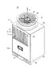
本発明の幾つかの実施形態に係るクーラユニット10は、図1及び図2に示すように、空気取込み開口を有し空気の流入が可能な正面(通風口面)12aと背面(通風口面)12c、及び空気流出開口を有し空気の流出が可能な上面(通風口面)12bを有するユニット本体12を備える。
ユニット本体12の内部には熱交換ユニット13が設けられ、ユニット本体12の上面12bには送風機22が設けられる。送風機22を稼働させることで、正面12a及び背面12cから流入し、熱交換ユニット13を通り上面12bからユニット本体12の外に流出する空気流aが形成される。
また、ユニット本体12の内部には、冷凍サイクル構成機器が設けられる。この冷凍サイクル構成機器には、後述するように、熱交換ユニット13を構成する熱交換パネル14が凝縮器として組み込まれる。
As shown in FIGS. 1 and 2, the
A
In addition, a refrigeration cycle component device is provided inside the unit
図示した実施形態では、図1及び図2に示すように、クーラユニット10のユニット本体12は直方体の形状を有している。
また、図1に示すように、ユニット本体12の内部で正面12a側に、上記冷凍サイクル構成機器の作動を制御する制御盤32が設けられる。正面12aの下部領域では、正面12aの下部領域を遮蔽するパネルの一部に開口が設けられ、この開口に制御盤32の表示部34が外側から視認可能なように配置されている。
また、図1及び図2に示すように、正面12a及び背面12cの上部領域は空気流入用の開口が形成され、これらの開口に格子36が設けられる。また、上面12bでは送風機22が収容される円筒形のフード37が設けられ、フード37に格子36が設けられる。これらの格子36によって、鳥などの侵入を抑制できる。
In the illustrated embodiment, as shown in FIGS. 1 and 2, the unit
Moreover, as shown in FIG. 1, the
As shown in FIGS. 1 and 2, air inflow openings are formed in the upper regions of the
本発明の幾つかの実施形態に係る熱交換ユニット13は、図3に示すように、複数の熱交換パネル14を備える。各熱交換パネル14は上下方向に配置され縦面を形成する仕切り板16と、前面(空気が流入する側の面)を斜め下向きに配置された板状の熱交換器18と、側面パネル20a及び20bとで構成され、逆三角形断面の内側空間Siを形成する。
これら複数の熱交換パネル14の仕切り板16の両側面部下端は、一対の支持フレーム44及び46に結合される。これによって、複数の熱交換パネル14は側面パネル20a及び20bが一方向に並ぶように並列に配置される。
各熱交換パネル14の仕切り板16の上端に第1の結合部70が形成され、第1の結合部70では、一つの熱交換パネル14の仕切り板16の上端が隣接配置された熱交換パネル14の仕切り板16の上端に結合される。
The
Lower ends of both side surfaces of the
A
かかる構成によれば、熱交換器18の前面に面して空気流入空間Sfを形成できるため、熱交換器18を通る空気の流量を確保でき、熱交換器18の伝熱効果を得ることができる。
また、熱交換器18は、ユニット本体12の内部で空気の流入が可能な側面に対して交差する方向に配置されるため、ユニット本体12の容積を増加させることなく、熱交換面積を確保できる。これによって、ユニット本体12をコンパクト化できる。
また、複数の熱交換パネル14が並列に配置されるため、熱交換器18の熱交換面を増加でき、伝熱効果を向上できる。また、かかる構成の熱交換ユニット13をユニット本体12の内部に配置した場合、従来のように、熱交換面が空気取込み開口に面して配置されない。そのため、飛来する飛石などの障害物が熱交換器に当たる可能性は、従来と比べて大幅に低減し、これによって、飛石などによる熱交換器の傷の発生を抑制できると共に、傷の発生に起因した腐食の進行を抑制できる。
また、複数の熱交換パネル14を一対の支持フレーム44及び46で固定するため、熱交換ユニット13をコンパクト化できる。
According to such a configuration, since the air inflow space Sf can be formed facing the front surface of the
Further, since the
Moreover, since the several
Further, since the plurality of
図示した実施形態では、図3に示すように、第1の結合部70は仕切り板16の上端で横方向に曲折されかつ仕切り板16の長手方向に延在するフランジ部で構成され、隣接配置された熱交換パネル14の一方の側面パネル20aに形成されたフランジ部71と結合される。
また、一対の支持フレーム44及び46はL形断面を有する直線形状のアングル材であり、これによって、熱交換ユニット13の支持構造をコンパクト化できる。
In the illustrated embodiment, as shown in FIG. 3, the
Further, the pair of support frames 44 and 46 are linear angle members having an L-shaped cross section, whereby the support structure of the
例示的な実施形態では、図3に示すように、各熱交換器18はその上端に熱交換器18の長手方向に延在し熱交換媒体rが流れる第1のヘッダパイプ23を有する。また、第1の結合部70は仕切り板16の上端で横方向に曲折されかつ仕切り板16の長手方向に延在するフランジ部で構成され、第1の結合部70は第1のヘッダパイプ23の上方を覆うように配置される。
これによって空気のショートサーキット、即ち、熱交換器18を通らずに上方へ抜ける空気流を防ぐと共に、第1のヘッダパイプ23を飛石などの障害物から保護できる。
In the exemplary embodiment, as shown in FIG. 3, each
As a result, a short circuit of air, that is, an air flow that passes upward without passing through the
例示的な実施形態では、図3に示すように、各熱交換器18は、熱交換器18の下端で熱交換器18の長手方向に延在し熱交換媒体rが流れる第2のヘッダパイプ24を有し、仕切り板16は仕切り板16の下端に形成され仕切り板16の長手方向に延在する第2の結合部48を有する。第2の結合部48の両端は一対の支持フレーム44及び46に結合され、第2のヘッダパイプ24は第2の結合部48に載置固定される。
第2の結合部48を有することで、各熱交換パネル14の支持フレーム44及び46に対する取付強度を向上できると共に、第2のヘッダパイプ24を第2の結合部48に載置固定することで、第2のヘッダパイプ24を安定支持できる。
In the exemplary embodiment, as shown in FIG. 3, each
By having the
例示的な実施形態では、図3に示すように、板状の熱交換器18の前面は同じ向きに配置される。
これによって、各熱交換パネル14において、熱交換器18の前面から内側空間Siに流入し、上部開口から上方に流出する空気流aは同一方向に並列に流れるため、空気流aの乱れを抑制でき、空気との熱交換効率を向上できる。
また、熱交換器18の前面が同じ向きに配置されるため、第1のヘッダパイプ23及び第2のヘッダパイプ24を設ける場合、これらのヘッダパイプを互いに干渉させずに配置できる。これによって、ヘッダパイプ配置のためのスペースを縮小できるため、熱交換ユニット13をコンパクト化できる。
In the exemplary embodiment, as shown in FIG. 3, the front surface of the plate-shaped
Thereby, in each
Further, since the front surface of the
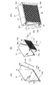
例示的な実施形態では、図4に示すように、第2の結合部48は横断面が溝形を有し開口が上向きに配置されたチャンネル材で構成され、このチャンネル材にドレン孔72が形成される。
第2の結合部48を上記構成のチャンネル材とすることで、熱交換パネル14の強度を高めることができると共に、チャンネル材に雨水などが溜まっても、ドレン孔72を形成することで排水できる。
図示した実施形態では、上記チャンネル材の長手方向に沿って複数のドレン孔72が形成されている。
In the exemplary embodiment, as shown in FIG. 4, the
By using the channel member having the above-described configuration as the
In the illustrated embodiment, a plurality of drain holes 72 are formed along the longitudinal direction of the channel material.
図示した実施形態では、図3に示すように、クーラユニット10は、ユニット本体12の内部に支持フレーム44及び46が水平方向に設けられ、各熱交換パネル14の仕切り板16の下端にチャンネル材48が形成され、チャンネル材48は支持フレーム44及び46間に架設され、支持フレーム44及び46に固定される。チャンネル材48に出口ヘッダパイプ24が載置される。
また、各熱交換パネル14の背面12c側の上端には、水平方向に管状の入口ヘッダ50が設けられ、入口ヘッダ50に各熱交換パネル14の入口ヘッダパイプ23が接続される。各熱交換パネル14の背面12c側の下端には、水平方向に管状の出口ヘッダ52が設けられ、出口ヘッダ52に各熱交換パネル14の出口ヘッダパイプ24が接続される。
入口ヘッダ50に熱交換媒体rが流入し、熱交換媒体rは入口ヘッダパイプ23を経て熱交換器18で空気と熱交換した後、出口ヘッダパイプ24を経て出口ヘッダ52から流出する。
かかる構成により、複数の熱交換パネル14の支持構造をコンパクト化できると共に、各熱交換パネル14の下部領域に遮蔽部材がないため、ユニット本体12の内部に流入した空気流aの流れが阻害されない。これによって、空気流aによる熱交換器18の冷却効果を向上できる。
In the illustrated embodiment, as shown in FIG. 3, the
In addition, a
The heat exchange medium r flows into the
With such a configuration, the support structure of the plurality of
例示的な実施形態では、図4(C)に示すように、少なくとも一方の側面パネル20bは熱交換パネル14に着脱可能に取り付けられる。
これによって、保守点検時や清掃時に側面パネル20bを取り外すことで、熱交換パネル14の内部の保守点検や清掃が容易になる。
図示した実施形態では、仕切り板16の一側にフランジ部16a及び16bが形成され、側面パネル20bはフランジ部16a及び16bにボルトなどの結合手段で取り付けられる。
In the exemplary embodiment, as shown in FIG. 4C, at least one
As a result, by removing the
In the illustrated embodiment,
例示的な実施形態では、第1のヘッダパイプ23及び第2のヘッダパイプ24を含む熱交換器18と、熱交換器18を除く各熱交換パネル14とは、異種材料で構成される。
そして、図4及び図5に示すように、これら異種材料間に絶縁材74a〜74fが介装される。
これによって、異種材料の接触面に発生する電蝕による損傷を抑制できる。
図示した実施形態では、図4(A)に示すように、第2の結合部(チャンネル材)48の溝内面に絶縁テープ74aが貼られる。絶縁テープ74aによって第2の結合部48と第2の結合部48に載置固定される第2のヘッダパイプ24との間を絶縁する。
In the exemplary embodiment, the
4 and 5, insulating
As a result, it is possible to suppress damage due to electrolytic corrosion occurring on the contact surfaces of different materials.
In the illustrated embodiment, as shown in FIG. 4A, an insulating
また、図4(B)に示すように、仕切り板16の一側に側面パネル20aが一体に形成され、熱交換器18が接する側面パネル20aに長尺の絶縁板74bが貼られ、フランジ部16a及び16bに絶縁板74c及び74dが貼られる。
側面パネル20a及びフランジ部16a、16bには熱交換器18の両側に設けられたアングル材76a及び76bが取り付けられる。これらの間に絶縁板74b〜74dを介装することで、仕切り板16と熱交換器18とを絶縁できる。
また、図4(B)に示すように、熱交換器18の一側に設けられるアングル材76bに絶縁板74eが貼られる。
また、図5に示すように、第1の結合部70の裏面に絶縁テープ74fが貼られる。絶縁テープ74fによって第1の結合部70と第1の結合部70の下方に位置する第1のヘッダパイプ23とを絶縁できる。
As shown in FIG. 4B, a
As shown in FIG. 4B, an insulating
Further, as shown in FIG. 5, an insulating
例示的な実施形態では、第1のヘッダパイプ23及び第2のヘッダパイプ24を含む熱交換器18はアルミ系材料で構成され、熱交換器18を除く熱交換パネル14は鉄系材料で構成される。
これらの異種材料間に絶縁材を介装することで、アルミ系材料で構成された熱交換器18の損傷を抑制できる。
In the exemplary embodiment, the
By interposing an insulating material between these different materials, damage to the
例示的な実施形態では、図6に示すように、熱交換器18において、第1のヘッダパイプ23と第2のヘッダパイプ24との間に、複数の扁平状熱交換チューブ26が互いに隙間を開けて並列に接続される。扁平状熱交換チューブ26の間にはコルゲートフィン28が接合される。
図7に示す実施形態では、扁平状熱交換チューブ26は板状の横断面を有し、熱交換媒体rが流れる多数の細孔26aが並列に形成されている。
かかる構成によって、扁平状熱交換チューブ26間の隙間を通過する空気と熱交換媒体rとの熱交換効率を大幅に向上できる。
In the exemplary embodiment, as shown in FIG. 6, in the
In the embodiment shown in FIG. 7, the flat
With this configuration, the heat exchange efficiency between the air passing through the gap between the flat
例示的な実施形態では、図3に示すように、第1のヘッダパイプ23は熱交換器18の扁平状熱交換チューブ26に熱交換媒体を供給する入口ヘッダパイプであり、第2のヘッダパイプ24は扁平状熱交換チューブ26から流出する熱交換媒体rを受ける出口ヘッダパイプである。
かかる構成によれば、扁平状熱交換チューブ26の上方に配置された入口ヘッダパイプ23から扁平状熱交換チューブ26の下方に配置された出口ヘッダパイプ24に対し、ヘッド差を利用して熱交換媒体を下降させることができる。これによって、伝熱面積を有効に利用できる。
また、板状の熱交換器18の前面が同じ向きに配置される複数の熱交換パネルに入口ヘッダパイプ23及び出口ヘッダパイプ24を設ける場合、各熱交換器18のヘッダパイプを互いに干渉させずに配置できる。これによって、ヘッダパイプ配置のためのスペースを縮小できるため、熱交換ユニット13をコンパクト化できる。
In the exemplary embodiment, as shown in FIG. 3, the
According to such a configuration, heat exchange is performed using the head difference from the
In addition, when the
本発明の幾つかの実施形態に係るクーラユニット10は、図8に示すように、ユニット本体12の内部に、熱交換パネル14が凝縮器として組み込まれる冷凍サイクル構成機器が設けられる。
複数の熱交換パネル14は、ユニット本体12の内部で並列に配置されると共に、ユニット本体12の正面12a(又は背面12c)に対して熱交換器18が交差する方向に配置される。
As shown in FIG. 8, the
The plurality of
これによって、ユニット本体12の外表面に形成される空気取込み開口の面積に制約がある場合でも、熱交換器18及びその熱交換面の面積を確保でき、空気との伝熱効果を得ることができる。
また、熱交換パネル14は逆三角形断面を形成することで、熱交換器18の前面に空気流入空間Sfを形成できるため、熱交換器18を通る空気流量を確保できる。
また、熱交換器18はユニット本体12の内部で正面12a及び背面12cに対して交差する方向に配置されるため、飛来する飛石などの障害物が熱交換器18に当たる可能性は、従来と比べて大幅に低減する。そのため、飛石などによる傷の発生を抑制できると共に、傷の発生に起因した腐食の進行を抑制できる。その他、熱交換パネル14が得られる上記作用効果を得ることができる。
As a result, even when the area of the air intake opening formed on the outer surface of the
Moreover, since the air inflow space Sf can be formed in the front surface of the
Moreover, since the
例示的な実施形態では、上記冷凍サイクル構成機器を循環する冷媒がNH3であり、熱交換器18は防錆処理が施される。
冷媒としてNH3を使用する場合、熱交換器18の腐食によってNH3が熱交換器18から漏れるのを防止する必要がある。
そこで、熱交換器18を防錆処理することで、熱交換器18の腐食の進行を抑制でき、NH3の漏れを抑制できる。例えば、熱交換器の材質をAl材とし、熱交換器18の表面を防錆処理をした後、防錆コーティング処理を行うことで、熱交換器18の腐食を抑制する。
In an exemplary embodiment, the refrigerant circulating through the refrigeration cycle components is NH 3 , and the
When NH 3 is used as the refrigerant, it is necessary to prevent NH 3 from leaking from the
Thus, by subjecting the
図示した実施形態では、図2に示すように、クーラユニット10は、背面12cの上部領域に2次冷媒として用いられるCO2がユニット本体内部の上部領域に設けられた蒸発器38に流入するCO2流入管40及び蒸発器38でNH3と熱交換して液化したCO2が流出するCO2流出管42が設けられる。
In the illustrated embodiment, as shown in FIG. 2, the
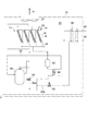
図示した実施形態では、図8に示すように、クーラユニット10は、ユニット本体12の内部に、熱交換ユニット13が凝縮器として組み込まれるNH3/CO2冷凍機54が設けられる。冷凍サイクル構成機器として、NH3冷媒が循環する冷媒循環路56に、圧縮機(例えばスクロール式圧縮機)58、熱交換器ユニット(凝縮器)13、レシーバタンク60、蒸発器38、膨張弁62、64、及び液ガス熱交換器66等が設けられる。
In the illustrated embodiment, as shown in FIG. 8, the
図8において、圧縮機58から吐出された高圧の冷媒ガス(NH3ガス)は、入口ヘッダ50及び入口ヘッダパイプ23を経て各熱交換パネル14の熱交換器18に送られる。冷媒ガスは熱交換器18の扁平状熱交換チューブ26を通る間に空気流aによって冷却され液化され、液化された冷媒液(NH3液)は一旦レシーバタンク60に貯留される。その後、冷媒液は液ガス熱交換器66で蒸発器38から戻る冷媒ガスを加熱した後、一部は冷媒流路56aを通り、膨張弁64を経て減圧され、圧縮機58から吐出される冷媒ガスの温度制御のために圧縮機58に注入される。
一方、蒸発器に向かう冷媒液は冷媒流路56bを通り、膨張弁62を経て減圧され、蒸発器38に送られ、蒸発器38でCO2流入管40から送られるCO2ガスを冷却して液化する。液化したCO2液は一旦レシーバタンク(不図示)に貯留された後利用先に送られる。
In FIG. 8, the high-pressure refrigerant gas (NH 3 gas) discharged from the
On the other hand, the refrigerant liquid toward the evaporator passes through the
図8に示すように、複数の熱交換パネル14はユニット本体内の上部領域に設けられ、正面12a及び背面12cの上部領域に設けられた空気取入れ開口の内側領域に設けられる。また、蒸発器38は上部領域で熱交換パネル14の隣りに配置される。
また、ユニット本体12の下部領域には、熱交換パネル14の下方に圧縮機58が設けられ、圧縮機58の隣りにレシーバタンク60、液ガス熱交換器66及び膨張弁62、64を含む計装機器が設けられる。
このように冷凍サイクル構成機器を配置することで、蒸発器38を上部領域に設け、CO2液を貯留するレシーバタンク(不図示)との間でヘッド差をもうけることで、蒸発器38で液化したCO2液を重力で上記レシーバタンクに送るサーモサイフォンサイクルを機能させることができる。これによって、蒸発器38と上記レシーバタンク間を循環させるCO2ポンプが必要なくなる。
As shown in FIG. 8, the plurality of
A
By arranging the refrigeration cycle components in this way, the
図示した実施形態では、図9に示すように、クーラユニット10は、空気の流入が可能な一側面の少なくとも一部をパンチングメタル30で覆うようにする。
これによって、飛来する飛石などの障害物や空気流aに随伴するごみ等の進入をパンチングメタル30で阻止できると共に、ユニット本体内部への熱交換のための空気流aの流入を許容できるため、伝熱効果を低下させない。
In the illustrated embodiment, as shown in FIG. 9, the
This allows the punching
パンチングメタル30は平坦な縦辺30a及び平坦な横辺30bとからなるL形断面を有する。縦辺30aはユニット本体12の内部を隠す装飾的機能を有すると共に、ユニット本体12の内部への空気流aの流入を可能にしている。横辺30bは側面パネル20b及び支持フレーム46に固定され、出口ヘッダ52を覆うように出口ヘッダ52の上方に配置される。このように、横辺30bによってNH3冷媒が流れる出口ヘッダ52を保護できると共に、ユニット本体12の内部への空気流aの流入を許容できる。
ユニット本体12の内部で上部領域と下部領域との間に仕切りがないため、縦辺30 aを通って流入した空気流aはその後熱交換器18の前面に上昇する流路を形成できる。これによって、熱交換器18を通過する空気流量を確保でき、冷媒ガスの冷却効果を高めることができる。
The punching
Since there is no partition between the upper region and the lower region inside the
本発明の幾つかの実施形態に係るユニット型熱交換器は、ユニット本体12、熱交換ユニット13及び送風機22を備える。ユニット本体12は、空気取込み開口を有し空気の流入が可能な正面12aと背面12c、及び空気流出開口を有し空気の流出が可能な上面12bを有する。ユニット本体12の内部には熱交換ユニット13が設けられ、ユニット本体12の上面12bには送風機22が設けられる。送風機22を稼働させることで、正面12a及び背面12cから流入し、熱交換ユニット13を通り上面12bからユニット本体12の外に流出する空気流aが形成される。
The unit heat exchanger according to some embodiments of the present invention includes a unit
かかる構成によって、板状の熱交換器18は、従来のように、ユニット本体の外表面に面して配置されるのではなく、ユニット本体12の内部で並列にかつ空気の流入が可能な一側面に対して交差する方向に配置されるため、熱交換面はユニット本体12の外表面の大きさの制約を受けなくなるため、熱交換面の確保が可能になる。
また、熱交換パネル14は逆三角形断面を形成することで、熱交換器18の前面に空気流入空間Sfを形成できるため、熱交換器18を通る空気流量を確保でき、伝熱効果を得ることができる。
また、熱交換器18は、ユニット本体12の内部で空気の流入が可能な一側面に対して交差する方向に配置されるため、飛来する飛石などの障害物が熱交換器18に当たる可能性は、従来と比べて大幅に低減する。そのため、飛石などによる傷の発生を抑制できると共に、傷の発生に起因した腐食の進行を抑制できる。その他、熱交換パネル14が得られる上記作用効果を得ることができる。
With such a configuration, the plate-shaped
Moreover, since the air exchange space Sf can be formed in the front surface of the
Further, since the
本発明の少なくとも一実施形態によれば、ユニット型の空調機器、給湯機器、及び冷凍機器等に適用される熱交換器において、熱交換面の面積確保が可能であり、かつ熱交換器の腐食の進行を抑制できる。 According to at least one embodiment of the present invention, in a heat exchanger applied to a unit type air conditioner, a hot water supply device, a refrigeration device, etc., the area of the heat exchange surface can be secured, and the corrosion of the heat exchanger Can be suppressed.
10 クーラユニット
12 ユニット本体
12a 正面(通風口面)
12b 上面(通風口面)
12c 背面(通風口面)
13 熱交換ユニット
14 熱交換パネル
16 仕切り板
18 熱交換器
20a、20b 側面パネル
22 送風機
23 入口ヘッダパイプ
24 出口ヘッダパイプ
26 扁平状熱交換チューブ
26a 細孔
28 コルゲートフィン
30 パンチングメタル
30a 縦辺
30b 横辺
32 制御盤
36 表示部
36 格子
37 フード
38 蒸発器
40 CO2流入管
42 CO2流出管
44、46 支持フレーム
48 第2の結合部(チャンネル材)
50 入口ヘッダ
52 出口ヘッダ
54 NH3/CO2冷凍機
56 冷媒循環路
56a、56b 冷媒流路
58 圧縮機
60 レシーバタンク
62、64 膨張弁
66 液ガス熱交換器
70、71 第1の結合部(フランジ部)
72 ドレン孔
74a、74b、74c、74d、74e、74f絶縁材(絶縁テープ又は絶縁板)
76a、76b アングル材
Sf 空気流入空間
Si 内側空間
a 空気流
r 熱交換媒体
10
12b Top surface (ventilation surface)
12c Back (ventilation surface)
13
50
72
76a, 76b Angle material Sf Air inflow space Si inner space a Air flow r Heat exchange medium
Claims (12)
前記複数の熱交換パネルの前記仕切り板の両側面部下端が結合されることで、前記複数の熱交換パネルを前記側面パネルが一方向に沿って並ぶように並列に配置するための一対の支持フレームと、
前記複数の熱交換パネルの前記仕切り板の上端が、隣接配置された前記熱交換パネルの前記仕切り板の上端に結合される第1の結合部と、
を備えることを特徴とする空冷式熱交換ユニット。 A plurality of heat exchange panels forming an inner space of an inverted triangular cross section by a partition plate that forms a vertical surface, a plate-like heat exchanger whose front surface is arranged obliquely downward, and a side panel;
A pair of support frames for arranging the plurality of heat exchange panels in parallel so that the side panels are aligned along one direction by joining lower ends of both side surfaces of the partition plates of the plurality of heat exchange panels. When,
A first coupling portion in which upper ends of the partition plates of the plurality of heat exchange panels are coupled to upper ends of the partition plates of the heat exchange panels disposed adjacent to each other;
An air-cooled heat exchange unit comprising:
前記第1の結合部は、前記仕切り板の上端で横方向に曲折されかつ前記仕切り板の長手方向に延在するフランジ部で構成されると共に、前記第1のヘッダパイプの上方を覆うように配置されることを特徴とする請求項1に記載の空冷式熱交換ユニット。 Each of the heat exchangers has a first header pipe that extends in the longitudinal direction of the heat exchanger at the upper end of the heat exchanger;
The first coupling portion is formed of a flange portion that is bent in a lateral direction at an upper end of the partition plate and extends in a longitudinal direction of the partition plate, and covers an upper portion of the first header pipe. The air-cooled heat exchange unit according to claim 1, wherein the air-cooled heat exchange unit is disposed.
前記仕切り板は、前記仕切り板の下端に形成され前記仕切り板の長手方向に延在する第2の結合部を有し、
前記第2の結合部の両端が前記一対の支持フレームに結合されると共に、前記第2のヘッダパイプは前記第2の結合部に載置固定されることを特徴とする請求項1又は2に記載の空冷式熱交換ユニット。 Each of the heat exchangers has a second header pipe that extends in the longitudinal direction of the heat exchanger at the lower end of the heat exchanger;
The partition plate has a second coupling portion formed at a lower end of the partition plate and extending in a longitudinal direction of the partition plate,
The both ends of the second coupling part are coupled to the pair of support frames, and the second header pipe is mounted and fixed to the second coupling part. The air-cooled heat exchange unit described.
これら異種材料の接触部には絶縁材が介装されることを特徴とする請求項1乃至3の何れか1項に記載の空冷式熱交換ユニット。 Each heat exchanger and the heat exchange panel excluding the heat exchanger are made of different materials,
The air-cooled heat exchange unit according to any one of claims 1 to 3, wherein an insulating material is interposed between the contact portions of these different materials.
前記チャンネル材にはドレン孔が形成されていることを特徴とする請求項3又は4の何れか1項に記載の空冷式熱交換ユニット。 The second coupling part is composed of a channel material having a groove shape in cross section and an opening arranged upward,
5. The air-cooled heat exchange unit according to claim 3, wherein a drain hole is formed in the channel material. 6.
複数の前記板状の熱交換器の前記前面は同じ向きに配置されることを特徴とする請求項1乃至5の何れか1項に記載の空冷式熱交換ユニット。 In the plurality of heat exchange panels,
The air-cooled heat exchange unit according to any one of claims 1 to 5, wherein the front surfaces of the plurality of plate-like heat exchangers are arranged in the same direction.
前記第1のヘッダパイプと前記第2のヘッダパイプ間に接続され、互いに隙間を有して並列に配置された複数の扁平状熱交換チューブと、
前記隙間に配置され前記複数の扁平状熱交換チューブに接合されたコルゲートフィンと、
を備えることを特徴とする請求項3乃至7の何れか1項に記載の空冷式熱交換ユニット。 The plate-shaped heat exchanger is
A plurality of flat heat exchange tubes connected between the first header pipe and the second header pipe and arranged in parallel with a gap therebetween;
Corrugated fins disposed in the gap and joined to the plurality of flat heat exchange tubes;
The air-cooled heat exchange unit according to any one of claims 3 to 7, further comprising:
前記第2のヘッダパイプは前記扁平状熱交換チューブから流出する冷媒を受ける出口ヘッダパイプであることを特徴とする請求項3乃至8の何れか1項に記載の空冷式熱交換ユニット。 The first header pipe is an inlet header pipe that supplies a refrigerant to the flat heat exchange tube,
The air-cooled heat exchange unit according to any one of claims 3 to 8, wherein the second header pipe is an outlet header pipe that receives a refrigerant flowing out of the flat heat exchange tube.
前記ユニット本体の内部に設けられ、前記空気の流入が可能な一側面に対して前記熱交換器が交差する方向に配置される請求項1乃至9の何れか1項に記載の空冷式熱交換ユニットと、
前記ユニット本体の上部に設けられ、前記空冷式熱交換ユニットの前記熱交換器の前面から前記内側空間に流入し、前記熱交換パネルの上部開口から流出する空気流路を形成するための送風機と、
を備えることを特徴とするユニット型熱交換器。 A unit body having a side surface through which air can flow in and a top surface through which air can flow out;
The air-cooled heat exchange according to any one of claims 1 to 9, wherein the air-cooled heat exchanger is disposed in a direction in which the heat exchanger intersects with one side surface that is provided inside the unit main body and into which the air can flow. Unit,
A blower provided at an upper portion of the unit main body, for forming an air flow path that flows into the inner space from the front surface of the heat exchanger of the air-cooled heat exchange unit and flows out from the upper opening of the heat exchange panel; ,
A unit-type heat exchanger comprising:
前記ユニット本体の内部に設けられ、前記空気の流入が可能な一側面に対して前記熱交換器が交差する方向に配置される請求項1乃至9の何れか1項に記載の空冷式熱交換ユニットと、
前記ユニット本体の上部に設けられ、前記空冷式熱交換ユニットの前記熱交換器の前面から前記内側空間に流入し、前記熱交換パネルの上部開口から流出する空気流路を形成するための送風機と、
前記ユニット本体の内部に設けられ、前記熱交換パネルが凝縮器として組み込まれる冷凍サイクル構成機器と、
を備えることを特徴とするクーラユニット。 A unit body having a side surface through which air can flow in and a top surface through which air can flow out;
The air-cooled heat exchange according to any one of claims 1 to 9, wherein the air-cooled heat exchanger is disposed in a direction in which the heat exchanger intersects with one side surface that is provided inside the unit main body and into which the air can flow. Unit,
A blower provided at an upper portion of the unit main body, for forming an air flow path that flows into the inner space from the front surface of the heat exchanger of the air-cooled heat exchange unit and flows out from the upper opening of the heat exchange panel; ,
A refrigeration cycle component device provided inside the unit main body, in which the heat exchange panel is incorporated as a condenser,
A cooler unit comprising:
前記板状の熱交換器は防錆処理が施されていることを特徴とする請求項11に記載のクーラユニット。 The refrigerant circulating in the refrigeration cycle component equipment is NH 3 ,
The cooler unit according to claim 11, wherein the plate-shaped heat exchanger is subjected to rust prevention treatment.
Priority Applications (1)
| Application Number | Priority Date | Filing Date | Title |
|---|---|---|---|
| JP2015251388A JP6603574B2 (en) | 2015-12-24 | 2015-12-24 | Air-cooled heat exchange unit, unit heat exchanger and cooler unit |
Applications Claiming Priority (1)
| Application Number | Priority Date | Filing Date | Title |
|---|---|---|---|
| JP2015251388A JP6603574B2 (en) | 2015-12-24 | 2015-12-24 | Air-cooled heat exchange unit, unit heat exchanger and cooler unit |
Publications (2)
| Publication Number | Publication Date |
|---|---|
| JP2017116170A JP2017116170A (en) | 2017-06-29 |
| JP6603574B2 true JP6603574B2 (en) | 2019-11-06 |
Family
ID=59234283
Family Applications (1)
| Application Number | Title | Priority Date | Filing Date |
|---|---|---|---|
| JP2015251388A Active JP6603574B2 (en) | 2015-12-24 | 2015-12-24 | Air-cooled heat exchange unit, unit heat exchanger and cooler unit |
Country Status (1)
| Country | Link |
|---|---|
| JP (1) | JP6603574B2 (en) |
Families Citing this family (3)
| Publication number | Priority date | Publication date | Assignee | Title |
|---|---|---|---|---|
| JP6742721B2 (en) * | 2015-12-24 | 2020-08-19 | 株式会社前川製作所 | Cooler unit |
| CN108562071B (en) * | 2018-04-19 | 2019-03-29 | 浙江国祥股份有限公司 | A kind of evaporative condenser |
| PL3745067T3 (en) * | 2019-05-29 | 2021-09-06 | Ovh | Heat exchanger assembly |
-
2015
- 2015-12-24 JP JP2015251388A patent/JP6603574B2/en active Active
Also Published As
| Publication number | Publication date |
|---|---|
| JP2017116170A (en) | 2017-06-29 |
Similar Documents
| Publication | Publication Date | Title |
|---|---|---|
| WO2013099897A1 (en) | Outdoor unit for refrigeration device | |
| JP6603574B2 (en) | Air-cooled heat exchange unit, unit heat exchanger and cooler unit | |
| JP6433582B2 (en) | Heat source unit | |
| WO2018100601A1 (en) | Air conditioner outdoor unit, and air conditioner provided with same | |
| JP5890705B2 (en) | Heat exchanger | |
| JP2008202889A (en) | Engine-driven heat pump | |
| JP6494384B2 (en) | Transformer for vehicle | |
| RU2708181C1 (en) | Heat exchanger installation | |
| JP6650752B2 (en) | Air-cooled heat exchange unit and cooler unit | |
| WO2016112834A1 (en) | Inter-row air conditioning heat exchanger, and inter-row air conditioner | |
| JPWO2021024406A1 (en) | Chilling unit and chilling unit system | |
| JP5720621B2 (en) | Air conditioner outdoor unit | |
| JP2018109455A (en) | Air-cooled type heat exchange unit and cooler unit | |
| JP5963958B2 (en) | Outdoor unit for air conditioner and method for manufacturing outdoor unit for air conditioner | |
| JP2013257095A (en) | Finless heat exchanger | |
| JP6218684B2 (en) | Air conditioner outdoor unit | |
| JP6742721B2 (en) | Cooler unit | |
| JP6902359B2 (en) | Heat pump unit | |
| JP2010091137A (en) | Heat exchanger | |
| JP2006056421A (en) | Heat exchanger for vehicle | |
| WO2023053280A1 (en) | Chilling unit and chilling unit system | |
| KR20140083287A (en) | Heat exchanger | |
| JP7313857B2 (en) | Finned-tube heat exchanger and transportation refrigeration equipment equipped with the same | |
| JP6890366B1 (en) | Radiant panel | |
| JP2019104303A (en) | Cooler for vehicle |
Legal Events
| Date | Code | Title | Description |
|---|---|---|---|
| A621 | Written request for application examination |
Free format text: JAPANESE INTERMEDIATE CODE: A621 Effective date: 20181102 |
|
| A977 | Report on retrieval |
Free format text: JAPANESE INTERMEDIATE CODE: A971007 Effective date: 20190926 |
|
| TRDD | Decision of grant or rejection written | ||
| A01 | Written decision to grant a patent or to grant a registration (utility model) |
Free format text: JAPANESE INTERMEDIATE CODE: A01 Effective date: 20191008 |
|
| A61 | First payment of annual fees (during grant procedure) |
Free format text: JAPANESE INTERMEDIATE CODE: A61 Effective date: 20191011 |
|
| R150 | Certificate of patent or registration of utility model |
Ref document number: 6603574 Country of ref document: JP Free format text: JAPANESE INTERMEDIATE CODE: R150 |
|
| R250 | Receipt of annual fees |
Free format text: JAPANESE INTERMEDIATE CODE: R250 |
|
| R250 | Receipt of annual fees |
Free format text: JAPANESE INTERMEDIATE CODE: R250 |