JP6218684B2 - Air conditioner outdoor unit - Google Patents
Air conditioner outdoor unit Download PDFInfo
- Publication number
- JP6218684B2 JP6218684B2 JP2014136831A JP2014136831A JP6218684B2 JP 6218684 B2 JP6218684 B2 JP 6218684B2 JP 2014136831 A JP2014136831 A JP 2014136831A JP 2014136831 A JP2014136831 A JP 2014136831A JP 6218684 B2 JP6218684 B2 JP 6218684B2
- Authority
- JP
- Japan
- Prior art keywords
- heat exchanger
- insulating member
- flat tube
- outdoor unit
- corrugated fin
- Prior art date
- Legal status (The legal status is an assumption and is not a legal conclusion. Google has not performed a legal analysis and makes no representation as to the accuracy of the status listed.)
- Expired - Fee Related
Links
Images


Landscapes
- Other Air-Conditioning Systems (AREA)
Description
本発明は、コルゲートフィン型熱交換器を搭載する空気調和機の室外機に関するものである。 The present invention relates to an outdoor unit of an air conditioner equipped with a corrugated fin heat exchanger.
従来のコルゲートフィン型熱交換器を搭載する空気調和機の室外機において、間隔を置いて平行に配置された2本の垂直なヘッダーパイプと、2本のヘッダーパイプの間に複数配置され、内部に設けた冷媒通路をヘッダーパイプの内部に連通させた水平な扁平チューブとを備えたサイドフロー方式のパラレルフロー型熱交換器を搭載したものがある。
そして、空気調和機の室外機の筐体底部をなすベースパンに、熱交換器のヘッダーパイプ下端を着座させる位置決め部を形成し、このヘッダーパイプ下端と位置決め部の間に、異種金属間の電気腐食防止対策としてキャップ状の絶縁部材を介在させ、ヘッダーパイプを位置決め部に挿入することで熱交換器を固定する室外機が開示されている(例えば特許文献1参照)。
In an outdoor unit of an air conditioner equipped with a conventional corrugated fin type heat exchanger, a plurality of two vertical header pipes arranged in parallel at intervals and two header pipes are arranged inside. There is a type equipped with a side flow type parallel flow heat exchanger equipped with a horizontal flat tube in which the refrigerant passage provided in the pipe is communicated with the inside of the header pipe.
Then, a positioning part for seating the lower end of the header pipe of the heat exchanger is formed on the base pan that forms the bottom of the casing of the outdoor unit of the air conditioner. Electricity between different metals is formed between the lower end of the header pipe and the positioning part. As an anti-corrosion measure, an outdoor unit that fixes a heat exchanger by interposing a cap-shaped insulating member and inserting a header pipe into a positioning portion is disclosed (for example, see Patent Document 1).
ここで、大型のコルゲートフィン型熱交換器を室外機に搭載する場合、上記のヘッダーパイプを位置決め部に挿入することによって熱交換器を室外機に固定するが、場合によっては絶縁部材を用いて熱交換器の扁平管が配置されている下端部を支える形で熱交換器を保持することがある。
この時、コルゲートフィン型熱交換器の扁平管はヘッダーパイプに比べ強度が弱いため、コルゲートフィン型熱交換器の大型化による重量の増加により、キャップ状の絶縁部材で支えられている扁平管に負荷が掛かることで、扁平管が変形する可能性がある。この扁平管の変形により、冷媒の流動性の低下に伴う熱交換器の性能の低下、又は場合によっては扁平管自体が破裂してしまうという問題点があった。
Here, when mounting a large corrugated fin type heat exchanger on an outdoor unit, the heat exchanger is fixed to the outdoor unit by inserting the header pipe into the positioning unit, but in some cases, an insulating member is used. The heat exchanger may be held in a form that supports the lower end portion where the flat tube of the heat exchanger is disposed.
At this time, since the flat tube of the corrugated fin heat exchanger is weaker than the header pipe, the weight of the corrugated fin heat exchanger is increased and the flat tube supported by the cap-shaped insulating member is increased. When a load is applied, the flat tube may be deformed. Due to the deformation of the flat tube, there has been a problem that the performance of the heat exchanger is lowered due to the decrease in the fluidity of the refrigerant, or the flat tube itself is ruptured in some cases.
本発明は、上記のような問題点を解決するためになされたもので、大型のコルゲートフィン型熱交換器を室外機に搭載し、輸送落下時に衝撃が加わった場合でも、扁平管が損傷することがない空気調和機の室外機を得ることを目的とする。 The present invention has been made to solve the above-described problems. A large corrugated fin-type heat exchanger is mounted on an outdoor unit, and a flat tube is damaged even when an impact is applied during transportation fall. It aims at obtaining the outdoor unit of the air conditioner which never happens.
本発明に係る空気調和機の室外機は、平行かつ垂直に配置された2本のヘッダーパイプ、及び前記2本のヘッダーパイプの間に配置され、前記2本のヘッダーパイプと連通する複数の扁平管を備えた熱交換器と、前記熱交換器が設置される底板と、前記ヘッダーパイプの下端部に設けられ、当該ヘッダーパイプを保持するとともに電気浸食を防止する第一の絶縁部材と、前記扁平管の下端部に設けられ、当該扁平管を保持するとともに電気浸食を防止する第二の絶縁部材と、を備え、前記第二の絶縁部材は、前記扁平管の側部を挟持する挟持部を備え、前記熱交換器と前記底板との間隙に介挿され、前記熱交換器と前記底板との間隙を埋めており、前記挟持部は、前記扁平管の下端と接触することなく、前記扁平管の側部のみを挟持して保持するものである。 An outdoor unit of an air conditioner according to the present invention includes two header pipes arranged in parallel and vertically, and a plurality of flats arranged between the two header pipes and communicating with the two header pipes. A heat exchanger provided with a tube, a bottom plate on which the heat exchanger is installed, a first insulating member that is provided at a lower end of the header pipe and holds the header pipe and prevents electric erosion, A second insulating member that is provided at a lower end portion of the flat tube and that holds the flat tube and prevents electric erosion, and the second insulating member sandwiches a side portion of the flat tube And is inserted in the gap between the heat exchanger and the bottom plate, and fills the gap between the heat exchanger and the bottom plate, and the clamping portion does not contact the lower end of the flat tube, Hold and hold only the side of the flat tube Is shall.
本発明によれば、上記構成の熱交換器の扁平管を熱交換器挟持部材で挟持することで、熱交換器の下端が絶縁部材に接することがなくなる。すなわち、扁平管の前後方向で拘束することで、自重方向に絶縁部材と接触させない。これにより、輸送落下時に衝撃が加わった場合でも、熱交換器の扁平管の損傷を防止することができる。 According to the present invention, the lower end of the heat exchanger is not in contact with the insulating member by sandwiching the flat tube of the heat exchanger having the above configuration with the heat exchanger sandwiching member. That is, by restraining in the front-rear direction of the flat tube, it is not brought into contact with the insulating member in its own weight direction. Thereby, even when an impact is applied during transportation, damage to the flat tube of the heat exchanger can be prevented.
図1は、本発明の空気調和機の室外機を正面から見た斜視図である。
図1に示されるように、本発明の空気調和機の室外機100の筐体は、正面から見て、上部に天面パネル1、底面に底板7、前面側に前面パネル2、右側面側に右側面パネル3、サービスカバー4及びバルブカバー5によって構成されている。
FIG. 1 is a perspective view of an outdoor unit of an air conditioner according to the present invention as viewed from the front.
As shown in FIG. 1, the housing of the
図2は、図1の空気調和機の室外機100の内部を示す斜視図である。
図2に示されるように、本発明の空気調和機の室外機100の内部は、正面から見て、左側に送風機室20aを有し、右側に機械室20bを有し、送風機室20a及び機械室20bはセパレータ6によって分けられている。また、室外機100内部の各部品は、脚部を有する底面の底板7の上に設置されている。
FIG. 2 is a perspective view showing the inside of the
As shown in FIG. 2, the interior of the
機械室20bには、圧縮機8と冷媒配管、そして電気品などが設置されている。室内機(図示せず)から送られた冷媒は、圧縮機8において圧縮され、冷媒配管を通り、送風機室20aに設置されているコルゲートフィン型熱交換器9に送られる。また、電気品は、各部品への電力供給等を行う。
The
送風機室20aには、L字状のコルゲートフィン型熱交換器9、プロペラファン10、ファンモーター11及びファンモーター固定部材12などが設置されている。送風機室20a背面側には、L字状のコルゲートフィン型熱交換器9が立設されている。なお、L字状のコルゲートフィン型熱交換器9は、コルゲートフィン型熱交換器9の短手方向の面を室外機100の左側面側に、コルゲートフィン型熱交換器9の長手方向の面を室外機100の背面側に面するように設けられている。
An L-shaped corrugated
また、コルゲートフィン型熱交換器9と外部との間で強制的に熱交換を行わせるため、コルゲートフィン型熱交換器9と前面パネル2との間に、プロペラファン10とプロペラファン10を駆動するファンモーター11及びそれらを保持するファンモーター固定部材12が設置されている。
Further, in order to force heat exchange between the corrugated
ファンモーター11を駆動し、プロペラファン10を回転させると、コルゲートフィン型熱交換器9の背面側から室外機100の内部へ空気が流入する。そして、その空気は、コルゲートフィン型熱交換器9及びプロペラファン10を通過し、室外機正面方向へ流出する。これにより、冷房運転中においては、コルゲートフィン型熱交換器9内の冷媒は空気によって強制的に冷却され、コルゲートフィン型熱交換器9を通過した空気は冷媒と熱交換することで加熱される。
When the
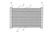
図3(a)は、コルゲートフィン型熱交換器9の全体図である。
図3(a)に示されるように、コルゲートフィン型熱交換器9は、ヘッダーパイプ9a、熱交換チューブである扁平管9b及びコルゲートフィン9cにより構成される。コルゲートフィン型熱交換器9は、左右両端にヘッダーパイプ9aを持つ。複数の扁平管9bは、左右両端のヘッダーパイプ9aの間に配置されている。さらに、それぞれの扁平管9bは、垂直方向に平行に間隔を置いて配置されている。
FIG. 3A is an overall view of the corrugated
As shown in FIG. 3A, the corrugated
図3(b)は、コルゲートフィン型熱交換器9の拡大図である。図3(b)に示されるように、コルゲートフィン9cは、垂直方向に平行に一定の間隔を置いて配置された扁平管9bの間を波形状に交互に縦列し設置されている。
ヘッダーパイプ9a、扁平管9b及びコルゲートフィン9cは、例えばアルミニウム等の熱伝導率の高い金属からなる。また、扁平管9b及びコルゲートフィン9cは、ロウ付け又は溶着されることで固定されている。
FIG. 3B is an enlarged view of the corrugated
The
図4(a)は、コルゲートフィン型熱交換器9の保持及び挟持部品群の組立図である。
図4(a)に示されるように、コルゲートフィン型熱交換器9の保持及び挟持部品群は、ヘッダーパイプ9a、セパレータ6との固定板金であるセパレータプレート13、底板7との固定板金である熱交プレート14、ヘッダー配置部の絶縁部材15及び扁平管配置部の絶縁部材16により構成されている。
FIG. 4A is an assembly view of the holding and clamping component group of the corrugated
As shown in FIG. 4A, the holding and clamping component group of the corrugated fin-
図4(b)は、上記図4(a)のコルゲートフィン型熱交換器9の保持及び挟持部品群の分解図である。
図4(b)に示されるように、ヘッダーパイプ9a及び扁平管9bの電気腐食を防止するため、室外機100を構成する各板金部品とコルゲートフィン型熱交換器9との隙間に絶縁部材を挿入する。
L字状のコルゲートフィン型熱交換器9の短手方向のヘッダーパイプ9aには、天面パネル1及び底板7との電気腐食を防止するため、ヘッダーパイプ9aの上端及び下端に、ヘッダー配置部の絶縁部材15がそれぞれ挿入されている。
一方、L字状のコルゲートフィン型熱交換器9の長手方向のヘッダーパイプ9aには、セパレータプレート13、熱交プレート14、天面パネル1及び底板7との電気腐食を防止するため、コルゲートフィン型熱交換器9との隙間にヘッダー配置部の絶縁部材15が挿入されている。
また、コルゲートフィン型熱交換器9の扁平管配置部と底板7との隙間においては、扁平管配置部の絶縁部材16を挿入している。
FIG. 4B is an exploded view of the holding and clamping component group of the corrugated
As shown in FIG. 4 (b), in order to prevent the electric corrosion of the
The
On the other hand, the
Further, in the gap between the flat tube placement portion of the corrugated
図5(a)は、コルゲートフィン型熱交換器9と絶縁部材の全体図である。また、図5(b)は、図5(a)のX−X断面図であり、図5(c)は、図5(a)のY−Y断面図であり、図5(d)は、図5(a)のZ−Z断面図である。
図5(b)及び図5(c)に示されるように、コルゲートフィン型熱交換器9は、ヘッダー配置部の絶縁部材15がヘッダーパイプ9aを垂直方向に保持することで、立設されている。
一方、図5(d)に示されるように、扁平管配置部の絶縁部材16は、コルゲートフィン型熱交換器9を挿入する断面がU字状の挿入部16g及びコルゲートフィン型熱交換器9を挟持する熱交換器挟持部材16fを備える。なお、熱交換器挟持部材16fは絶縁部材で作られている。
コルゲートフィン型熱交換器9は、挿入部16gに挿入され、熱交換器挟持部材16fは、室外機100の前面側及び背面側からコルゲートフィン型熱交換器9を挟持する。この際、熱交換器挟持部材16fは、コルゲートフィン型熱交換器9の扁平管9bの下端と、断面U字状の挿入部16gの底部との間に間隙が形成された状態で挟持する。これにより、扁平管配置部の絶縁部材16は、図5(a)中のA方向(室外機100の前後方向)へのずれを防止する拘束具として作用する。
FIG. 5A is an overall view of the corrugated
As shown in FIGS. 5B and 5C, the corrugated
On the other hand, as shown in FIG. 5 (d), the insulating
The corrugated fin
以上のように、コルゲートフィン型熱交換器9の扁平管9bの下端を、絶縁部材で作られた熱交換器挟持部材16fで挟持して固定することで、断面U字状の挿入部16gの底部と接触させずに、電気腐食を防止する本来の機能を保ちながら、輸送落下時の衝撃による扁平管9bの損傷を防ぐことが可能な空気調和機の室外機100を得ることが出来る。
As described above, the lower end of the
図6(a)は、コルゲートフィン型熱交換器9の扁平管配置部の絶縁部材16の取り付け状態を示す全体図である。
図6(a)に示されるように、扁平管配置部の絶縁部材16は、両端部に配置されたフック16aを底板7の背面から垂直に起こされたフランジ7aに引っ掛けて仮固定した後、底板7と扁平管配置部の絶縁部材16とをねじ17で固定することで取り付けられる。
FIG. 6A is an overall view showing an attached state of the insulating
As shown in FIG. 6 (a), the insulating
図6(b)は、図6(a)の扁平管配置部の絶縁部材16を示すA方向図である。
扁平管配置部の絶縁部材16は、フランジ7aの形状に合わせたリブ16cを持っているため、図6(a)中のC方向(室外機100の長手方向)の任意の位置で取り付けが可能である。
FIG. 6B is an A direction view showing the insulating
Since the insulating
図6(c)は、図6(a)の扁平管配置部の絶縁部材16を示すB方向図である。
扁平管配置部の絶縁部材16をフランジ7aに引っ掛けた後、フック16aとフランジ7aとの間に隙間があると扁平管配置部の絶縁部材16が安定しない。そこで、安定性を持たせるためにフック16aに挿入安定用リブ16bを立てている。この挿入安定用リブ16bがフランジ7aに引っ掛かることにより、扁平管配置部の絶縁部材16が安定する。
FIG.6 (c) is a B direction figure which shows the insulating
After the insulating
図7は、本発明の空気調和機の室外機100を背面から見た斜視図である。
上述したように、コルゲートフィン型熱交換器9は、熱交換器挟持部材16fによって、コルゲートフィン型熱交換器9の扁平管配置部の下端が底板7に接触しないように挟持されている。これにより、コルゲートフィン型熱交換器9の下端と底板7との間には隙間が生じている。
そこで、扁平管配置部の絶縁部材16に、コルゲートフィン型熱交換器9の下端と底板7との隙間を埋める略直方体の形状(以下、隙間を埋める形状16dという)を設けた。これにより、上記隙間から異物等が侵入することがなくなり、底板7に配置された排水口が閉塞することがなくなる。
FIG. 7 is a perspective view of the
As described above, the corrugated
Therefore, the insulating
図8(a)は、コルゲートフィン型熱交換器9の扁平管配置部の絶縁部材16の排水用長方形穴を示す全体図である。図8(b)は、図8(a)の排水用長方形穴を示すA方向図であり、図8(c)は、図8(a)の排水用長方形穴を示すB方向図である。
図8(b)及び図8(c)に示されるように、コルゲートフィン型熱交換器9の挿入部16gの下面及び側面に排水用長方形穴16eが配置されている。挿入部16gはコルゲートフィン型熱交換器9が挿入される箇所であり、空気中の水分がコルゲートフィン型熱交換器9等で結露して生じるドレン水等が滴り落ちて、挿入部16gに滞留することがある。そして、このドレン水等が原因となってコルゲートフィン型熱交換器9を構成するアルミニウムが腐食したり、又は寒冷地の場合は、コルゲートフィン型熱交換器9等に付着した氷の成長によって扁平管9bなどが損傷したりすることがある。そこで、挿入部16gに排水用長方形穴16eを設け、挿入部16gに滴り落ちたドレン水等を排水することで上記の事象を防止することが可能となる。
FIG. 8A is an overall view showing a drainage rectangular hole in the insulating
As shown in FIGS. 8B and 8C, drainage
なお、本実施の形態において、扁平管配置部の絶縁部材16に挿入部16gを1つ設けた場合を説明しているが、本発明はこれに限定されず、2つ以上の挿入部16gを設けても良い。挿入部16gを2つ以上設けた場合、コルゲートフィン型熱交換器9を挟持する箇所が増えるため、より安定してコルゲートフィン型熱交換器9を保持することができる。
また、本実施の形態において、扁平管配置部の絶縁部材16をコルゲートフィン型熱交換器9の長手方向に設けた場合を説明しているが、本発明はこれに限定されず、コルゲートフィン型熱交換器9の短手方向に設けても良い。コルゲートフィン型熱交換器9の短手方向に扁平管配置部の絶縁部材16を設けた場合、図6(a)中のC方向(室外機100の左右方向)の拘束具として作用することができる。
また、本実施の形態において、扁平管配置部の絶縁部材16にフック16aを2つ設けた場合を説明しているが、本発明はこれに限定されず、3つ以上のフック16aを設けても良い。
また、本実施の形態において、排水用長方形穴16eを長方形の穴としているが、本発明はこれに限定されず、丸形状や三角形状など他の形状にしても良い。
In addition, in this Embodiment, although the case where the one
Moreover, in this Embodiment, although the case where the insulating
Moreover, in this Embodiment, although the case where the two
Moreover, in this Embodiment, although the
なお、コルゲートフィン型熱交換器9は、本発明における「熱交換器」に相当する。また、ヘッダー配置部の絶縁部材は、本発明における「第一の絶縁部材」に相当し、扁平管配置部の絶縁部材16は、本発明における「第二の絶縁部材」に相当する。また、熱交換器挟持部材16fは、本発明における「挟持部」に相当する。また、排水用長方形穴16eは、本発明における「排水用の穴」に相当する。
The corrugated
1 天面パネル、2 前面パネル、3 右側面パネル、4 サービスカバー、5 バルブカバー、6 セパレータ、7 底板、7a フランジ、8 圧縮機、9 コルゲートフィン型熱交換器、9a ヘッダーパイプ、9b 扁平管、9c コルゲートフィン、10 プロペラファン、11 ファンモーター、12 ファンモーター固定部材、13 セパレータプレート、14 熱交プレート、15 ヘッダー配置部の絶縁部材、16 扁平管配置部の絶縁部材、16a フック、16b 挿入安定用リブ、16c 位置決め用リブ、16d 隙間を埋める形状、16e 排水用長方形穴、16f 熱交換器挟持部材、16g 挿入部、17 ねじ、20a 送風機室、20b 機械室、100 室外機。
1 top panel, 2 front panel, 3 right panel, 4 service cover, 5 valve cover, 6 separator, 7 bottom plate, 7a flange, 8 compressor, 9 corrugated fin heat exchanger, 9a header pipe, 9b
Claims (5)
前記熱交換器が設置される底板と、
前記ヘッダーパイプの下端部に設けられ、当該ヘッダーパイプを保持するとともに電気浸食を防止する第一の絶縁部材と、
前記扁平管の下端部に設けられ、当該扁平管を保持するとともに電気浸食を防止する第二の絶縁部材と、
を備え、
前記第二の絶縁部材は、
前記扁平管の側部を挟持する挟持部を備え、
前記熱交換器と前記底板との間隙に介挿され、前記熱交換器と前記底板との間隙を埋めており、
前記挟持部は、前記扁平管の下端と接触することなく、前記扁平管の側部のみを挟持して保持する
ことを特徴とする空気調和機の室外機。 A heat exchanger comprising two header pipes arranged in parallel and vertically, and a plurality of flat tubes arranged between the two header pipes and communicating with the two header pipes;
A bottom plate on which the heat exchanger is installed;
A first insulating member provided at a lower end portion of the header pipe and holding the header pipe and preventing electric erosion;
A second insulating member provided at a lower end portion of the flat tube and holding the flat tube and preventing electric erosion;
With
The second insulating member is
A clamping part for clamping the side part of the flat tube;
Inserted in the gap between the heat exchanger and the bottom plate, filling the gap between the heat exchanger and the bottom plate,
The outdoor unit of an air conditioner, wherein the clamping unit clamps and holds only a side portion of the flat tube without contacting a lower end of the flat tube.
ことを特徴とする請求項1に記載の空気調和機の室外機。 The sandwiching portion has a U-shaped section, and the flat tube is inserted into the U-shaped section, and a lower end of the flat tube and a bottom of the U-shaped section The outdoor unit for an air conditioner according to claim 1, wherein only the side portion of the flat tube is sandwiched and held in a state where a gap is formed therebetween.
前記底板は、
前記底板から垂直に起こされ、前記第二の絶縁部材が取付けられるフランジを備え、
前記第二の絶縁部材は、
前記フランジと掛合されるフックを複数有し、前記フランジと前記第二の絶縁部材とが前記フックを介して掛合されることで、前記第二の絶縁部材が前記フランジに取付けられる、
ことを特徴とする請求項1又は2に記載の空気調和機の室外機。 The heat exchanger is erected on the bottom plate via the first insulating member and the second insulating member;
The bottom plate is
A flange that is raised vertically from the bottom plate and to which the second insulating member is attached;
The second insulating member is
A plurality of hooks engaged with the flange, the second insulating member is attached to the flange by engaging the flange and the second insulating member via the hook;
The outdoor unit for an air conditioner according to claim 1 or 2 , wherein the outdoor unit is an air conditioner.
前記フランジに係合する形状をなし、かつ、前記第二の絶縁部材の前記フランジ上での位置を決める位置決め用リブを備え、前記位置決め用リブが前記フランジと係合することで、前記第二の絶縁部材が前記フランジ上で位置決めされる、
ことを特徴とする請求項3に記載の空気調和機の室外機。 The second insulating member is
A positioning rib for determining the position of the second insulating member on the flange is provided, and the positioning rib is engaged with the flange. An insulating member is positioned on the flange;
The outdoor unit for an air conditioner according to claim 3 .
排水用の穴を少なくとも1つ備えた、
ことを特徴とする請求項1〜請求項4の何れか一項に記載の空気調和機の室外機。 The second insulating member is
With at least one drainage hole,
The outdoor unit of the air conditioner as described in any one of Claims 1-4 characterized by the above-mentioned.
Priority Applications (1)
| Application Number | Priority Date | Filing Date | Title |
|---|---|---|---|
| JP2014136831A JP6218684B2 (en) | 2014-07-02 | 2014-07-02 | Air conditioner outdoor unit |
Applications Claiming Priority (1)
| Application Number | Priority Date | Filing Date | Title |
|---|---|---|---|
| JP2014136831A JP6218684B2 (en) | 2014-07-02 | 2014-07-02 | Air conditioner outdoor unit |
Publications (3)
| Publication Number | Publication Date |
|---|---|
| JP2016014505A JP2016014505A (en) | 2016-01-28 |
| JP2016014505A5 JP2016014505A5 (en) | 2016-06-30 |
| JP6218684B2 true JP6218684B2 (en) | 2017-10-25 |
Family
ID=55230825
Family Applications (1)
| Application Number | Title | Priority Date | Filing Date |
|---|---|---|---|
| JP2014136831A Expired - Fee Related JP6218684B2 (en) | 2014-07-02 | 2014-07-02 | Air conditioner outdoor unit |
Country Status (1)
| Country | Link |
|---|---|
| JP (1) | JP6218684B2 (en) |
Families Citing this family (2)
| Publication number | Priority date | Publication date | Assignee | Title |
|---|---|---|---|---|
| EP3367008B1 (en) | 2016-07-25 | 2019-12-25 | Mitsubishi Electric Corporation | Outdoor unit for air conditioner |
| CN108204635A (en) * | 2018-01-17 | 2018-06-26 | 珠海格力电器股份有限公司 | Connecting structure of sheet metal part, outdoor unit and air conditioner |
Family Cites Families (3)
| Publication number | Priority date | Publication date | Assignee | Title |
|---|---|---|---|---|
| JPS5844303Y2 (en) * | 1979-12-25 | 1983-10-07 | ダイキン工業株式会社 | outdoor unit |
| JP2000094944A (en) * | 1998-09-24 | 2000-04-04 | Denso Corp | Air conditioning system for vehicle |
| JP5948867B2 (en) * | 2011-12-28 | 2016-07-06 | ダイキン工業株式会社 | Outdoor unit |
-
2014
- 2014-07-02 JP JP2014136831A patent/JP6218684B2/en not_active Expired - Fee Related
Also Published As
| Publication number | Publication date |
|---|---|
| JP2016014505A (en) | 2016-01-28 |
Similar Documents
| Publication | Publication Date | Title |
|---|---|---|
| WO2016117443A1 (en) | Heat exchange unit for air conditioning device | |
| US9657996B2 (en) | Flat tube heat exchanger and outdoor unit of air-conditioning apparatus including the heat exchanger | |
| EP3006842B1 (en) | Outdoor unit for air conditioner | |
| EP2754974B1 (en) | Outdoor unit of air-conditioning apparatus | |
| JP5447580B2 (en) | Air conditioner outdoor unit | |
| JP6156323B2 (en) | Outdoor unit for heat exchanger assembly and refrigeration system | |
| JP5360186B2 (en) | Air conditioner outdoor unit | |
| JP5955233B2 (en) | Air conditioner outdoor unit | |
| JP6469221B2 (en) | Outdoor unit for air conditioner and method for manufacturing outdoor unit for air conditioner | |
| JP6218684B2 (en) | Air conditioner outdoor unit | |
| JP2016084995A (en) | Outdoor unit of refrigeration device | |
| WO2015097761A1 (en) | Heat exchanger and outdoor unit provided with this heat exchanger | |
| US20210270473A1 (en) | Heat exchanger | |
| JP5516387B2 (en) | Refrigeration unit outdoor unit | |
| JP5634808B2 (en) | Air conditioner outdoor unit | |
| JP6099500B2 (en) | Outdoor unit and heat pump system using the outdoor unit | |
| JP5963958B2 (en) | Outdoor unit for air conditioner and method for manufacturing outdoor unit for air conditioner | |
| JP2015108482A (en) | Outdoor equipment of air conditioner | |
| US20230052303A1 (en) | Outdoor unit for air-conditioning apparatus | |
| JP4858387B2 (en) | Air conditioner outdoor unit | |
| WO2021192030A1 (en) | Heat exchanger, air conditioning device and method for manufacturing heat exchanger | |
| JP6635131B2 (en) | Air conditioner outdoor unit | |
| JP6593299B2 (en) | Heat exchanger | |
| JP5609624B2 (en) | Refrigeration unit outdoor unit | |
| JP2019132546A (en) | Outdoor unit of air conditioning device |
Legal Events
| Date | Code | Title | Description |
|---|---|---|---|
| A521 | Request for written amendment filed |
Free format text: JAPANESE INTERMEDIATE CODE: A523 Effective date: 20160517 |
|
| A621 | Written request for application examination |
Free format text: JAPANESE INTERMEDIATE CODE: A621 Effective date: 20160517 |
|
| A977 | Report on retrieval |
Free format text: JAPANESE INTERMEDIATE CODE: A971007 Effective date: 20170324 |
|
| A131 | Notification of reasons for refusal |
Free format text: JAPANESE INTERMEDIATE CODE: A131 Effective date: 20170404 |
|
| A521 | Request for written amendment filed |
Free format text: JAPANESE INTERMEDIATE CODE: A523 Effective date: 20170601 |
|
| TRDD | Decision of grant or rejection written | ||
| A01 | Written decision to grant a patent or to grant a registration (utility model) |
Free format text: JAPANESE INTERMEDIATE CODE: A01 Effective date: 20170829 |
|
| A61 | First payment of annual fees (during grant procedure) |
Free format text: JAPANESE INTERMEDIATE CODE: A61 Effective date: 20170926 |
|
| R150 | Certificate of patent or registration of utility model |
Ref document number: 6218684 Country of ref document: JP Free format text: JAPANESE INTERMEDIATE CODE: R150 |
|
| R250 | Receipt of annual fees |
Free format text: JAPANESE INTERMEDIATE CODE: R250 |
|
| LAPS | Cancellation because of no payment of annual fees |