JP6597145B2 - Rotating electric machine and manufacturing method thereof - Google Patents
Rotating electric machine and manufacturing method thereof Download PDFInfo
- Publication number
- JP6597145B2 JP6597145B2 JP2015197150A JP2015197150A JP6597145B2 JP 6597145 B2 JP6597145 B2 JP 6597145B2 JP 2015197150 A JP2015197150 A JP 2015197150A JP 2015197150 A JP2015197150 A JP 2015197150A JP 6597145 B2 JP6597145 B2 JP 6597145B2
- Authority
- JP
- Japan
- Prior art keywords
- coil end
- terminal
- coil
- groove
- stator
- Prior art date
- Legal status (The legal status is an assumption and is not a legal conclusion. Google has not performed a legal analysis and makes no representation as to the accuracy of the status listed.)
- Active
Links
Images


Landscapes
- Windings For Motors And Generators (AREA)
- Insulation, Fastening Of Motor, Generator Windings (AREA)
- Manufacture Of Motors, Generators (AREA)
Description
この明細書における開示は、回転電機およびその製造方法に関する。 The disclosure in this specification relates to a rotating electrical machine and a method for manufacturing the same.
特許文献1ないし特許文献4は、回転電機およびその製造方法を開示する。この技術では、ステータに設けられたインシュレータ(ボビン)に、コイル端を案内するためのガイド溝(112C)が設けられている。コイル端は、ガイド溝の中に配置される。ガイド溝は、コイル端を、端子の近傍に位置付ける。従来技術として列挙された先行技術文献の記載内容は、この明細書における技術的要素の説明として、参照により援用される。 Patent Documents 1 to 4 disclose a rotating electrical machine and a manufacturing method thereof. In this technique, an insulator (bobbin) provided in the stator is provided with a guide groove (112C) for guiding a coil end. The coil end is disposed in the guide groove. The guide groove positions the coil end in the vicinity of the terminal. The contents of the prior art documents listed as the prior art are incorporated by reference as an explanation of the technical elements in this specification.
ひとつの観点において、特許文献4の構造では、コイル端をガイド溝に収容する作業と、コイル端を端子に接触するように曲げる作業とが困難である。このため、作業中に、コイル端が、ガイド溝から外れることがある。また、コイル端を望ましい形状に安定的に曲げることが困難である。 In one aspect, in the structure of Patent Document 4, it is difficult to work to house the coil end in the guide groove and to bend the coil end so as to contact the terminal. For this reason, a coil end may remove | deviate from a guide groove during an operation | work. In addition, it is difficult to bend the coil end stably into a desired shape.
別の観点では、特許文献4は、ガイド溝とコイル端との嵌め合いの強さについて、何ら開示していない。しかし、緩すぎる嵌め合いは、コイル端と端子とを接続する工程において、コイル端の望ましくない不安定な移動を許し、望ましい接続状態の形成を阻害することがある。また、堅すぎる嵌め合いは、コイル端と端子とを接続する工程において、端子へ適合するためのコイル端の望ましい移動をも阻害し、望ましい接続状態の形成を阻害することがある。 From another viewpoint, Patent Document 4 does not disclose any strength of fitting between the guide groove and the coil end. However, a too loose fit may allow undesired and unstable movement of the coil end in the process of connecting the coil end and the terminal, and hinder the formation of a desired connection state. In addition, the fitting that is too tight may hinder the desired movement of the coil end for fitting to the terminal in the step of connecting the coil end and the terminal, and may hinder the formation of a desired connection state.
上述の観点において、または言及されていない他の観点において、回転電機およびその製造方法にはさらなる改良が求められている。 In the above-mentioned viewpoints or other aspects not mentioned, further improvement is required for the rotating electrical machine and the manufacturing method thereof.
開示されるひとつの目的は、望ましい接続状態の形成に適した回転電機およびその製造方法を提供することである。 One disclosed object is to provide a rotating electrical machine suitable for forming a desired connection state and a method for manufacturing the same.
開示される他のひとつの目的は、望ましい接続状態の形成に適したコイル端の案内が可能な回転電機およびその製造方法を提供することである。 Another object of the present disclosure is to provide a rotating electrical machine capable of guiding a coil end suitable for forming a desired connection state and a manufacturing method thereof.
この明細書に開示された複数の態様は、それぞれの目的を達成するために、互いに異なる技術的手段を採用する。特許請求の範囲および/またはこの項に記載した括弧内の符号は、後述する実施形態の部分との対応関係を示すものであって、技術的範囲を限定するものではない。 A plurality of aspects disclosed in this specification adopt different technical means to achieve each purpose. The reference numerals in parentheses described in the claims and / or in this section indicate the correspondence with the embodiments described later, and do not limit the technical scope.
ひとつの態様により、回転電機が開示される。回転電機は、ステータコイル(33)の端部であるコイル端(33a)と、コイル端が接続される端子(71)と、コイル端を収容することにより端子に向けてコイル端を案内する溝(43)を区画形成する案内部(36)とを備えている。案内部は、溝におけるコイル端の規定の位置に設けられ、コイル端と接触することにより変形している位置決め部(47)と、溝の入口に設けられ、コイル端の直径(DC)より大きく、かつ位置決め部の幅(WN)より大きい幅(WW)を有し、変形していない入口部(46、446、546、646)とを備える。 According to one aspect, a rotating electrical machine is disclosed. The rotating electrical machine includes a coil end (33a) that is an end of the stator coil (33), a terminal (71) to which the coil end is connected, and a groove that guides the coil end toward the terminal by accommodating the coil end. And a guide part (36) for partitioning (43). The guide portion is provided at a predetermined position of the coil end in the groove, and is positioned at the position of the positioning portion (47) deformed by contact with the coil end. and have a width of the positioning portion (WN) is greater than the width (WW), and a inlet portion undeformed (46,446,546,646).
回転電機は、コイル端を端子に向けて案内するための溝に、位置決め部と、入口部とを有している。位置決め部は、コイル端と接触することにより変形している。位置決め部は、コイル端と端子とが望ましい接続状態になるように、コイル端を位置付けることができる。さらに、案内部は、溝の入口に設けられた入口部を有している。入口部の幅は、コイル端の直径より大きく、かつ、位置決め部の幅より大きい。入口部は、位置決め部より緩くコイル端を位置付けることができる。コイル端は、入口部を経由して位置決め部に向けて操作される。コイル端が溝の中に入れられるとき、コイル端は、入口部において緩く位置づけられた後に、位置決め部に向けて操作される。このため、位置決め部に向けてコイル端を容易に操作することができる。 The rotating electrical machine has a positioning portion and an inlet portion in a groove for guiding the coil end toward the terminal. The positioning part is deformed by contacting the coil end. The positioning unit can position the coil end so that the coil end and the terminal are in a desired connection state. Further, the guide part has an inlet part provided at the inlet of the groove. The width of the inlet portion is larger than the diameter of the coil end and larger than the width of the positioning portion. The inlet portion can position the coil end more loosely than the positioning portion. The coil end is operated toward the positioning portion via the inlet portion. When the coil end is placed in the groove, the coil end is loosely positioned at the inlet and then manipulated toward the positioning portion. For this reason, a coil end can be easily operated toward a positioning part.
ひとつの態様により、回転電機が開示される。回転電機は、ステータコイル(33)の端部であるコイル端(33a)と、コイル端が接続される端子(71)と、コイル端を収容することにより端子に向けて前記コイル端を案内する溝(43)を区画形成する案内部(36)とを備えており、案内部は、溝におけるコイル端の規定の位置に設けられ、コイル端と接触することにより変形している位置決め部(47)と、溝の入口に設けられ、コイル端の直径(DC)より大きく、かつ位置決め部の幅(WN)より大きい幅(WW)を有する入口部(46、446、546、646)とを備え、案内部は、薄い板状に形成されており、コイル端と接触することにより変形する薄板部(44)を有し、薄板部は、入口部に設けられることなく、溝の奥である位置決め部にのみ設けられている。
ひとつの態様により、回転電機の製造方法が開示される。回転電機は、ステータコイル(33)の端部であるコイル端(33a)と、コイル端が接続される端子(71)と、コイル端を収容することにより端子に向けてコイル端を案内する溝(43)を区画形成する案内部(36)とを備える。回転電機の製造方法は、溝の入口に設けられ、コイル端の直径(DC)より大きい幅(WW)を有する入口部(46、446、546、646)にコイル端を緩く位置付けること、溝におけるコイル端の規定の位置に設けられた位置決め部(47)に向けて、コイル端の移動では変形しないように形成されている入口部を経由してコイル端を移動させること、位置決め部においてコイル端と案内部とを接触させることにより案内部を変形させコイル端を堅く位置付けること、および位置決め部によってコイル端を位置づけた状態で、コイル端と端子とを接続することを含む。
According to one aspect, a rotating electrical machine is disclosed. The rotating electric machine guides the coil end toward the terminal by accommodating the coil end (33a), which is the end of the stator coil (33), the terminal (71) to which the coil end is connected, and the coil end. And a guide portion (36) for defining and forming the groove (43). The guide portion is provided at a predetermined position of the coil end in the groove and is deformed by contact with the coil end (47). ) And an inlet portion (46, 446, 546, 646) provided at the inlet of the groove and having a width (WW) larger than the diameter (DC) of the coil end and larger than the width (WN) of the positioning portion. The guide portion is formed in a thin plate shape, and has a thin plate portion (44) that is deformed by contact with the coil end, and the thin plate portion is positioned at the back of the groove without being provided at the inlet portion. It is provided only in the department.
According to one aspect, a method for manufacturing a rotating electrical machine is disclosed. The rotating electrical machine includes a coil end (33a) that is an end of the stator coil (33), a terminal (71) to which the coil end is connected, and a groove that guides the coil end toward the terminal by accommodating the coil end. And a guide section (36) for defining (43). A method for manufacturing a rotating electrical machine includes loosely positioning a coil end at an inlet portion (46, 446, 546, 646) provided at an entrance of a groove and having a width (WW) larger than a diameter (DC) of the coil end. The coil end is moved toward the positioning portion (47) provided at a predetermined position of the coil end via an inlet portion formed so as not to be deformed by the movement of the coil end. The guide portion is deformed by bringing the guide portion into contact with each other and the coil end is positioned firmly, and the coil end and the terminal are connected in a state where the coil end is positioned by the positioning portion.
回転電機は、コイル端を端子に向けて案内するための溝に、位置決め部と、入口部とを有している。コイル端は、入口部に緩く位置づけられた後に、位置決め部に堅く位置づけられる。このとき、案内部は変形する。位置決め部は、コイル端と端子とが望ましい接続状態になるように、コイル端を位置付けることができる。入口部は、位置決め部より緩くコイル端を位置付ける。コイル端は、入口部を経由して位置決め部に向けて操作される。コイル端が溝の中に入れられるとき、コイル端は、入口部において緩く位置づけられた後に、位置決め部に向けて操作される。このため、位置決め部に向けてコイル端を容易に操作することができる。 The rotating electrical machine has a positioning portion and an inlet portion in a groove for guiding the coil end toward the terminal. After the coil end is loosely positioned at the inlet portion, it is firmly positioned at the positioning portion. At this time, the guide portion is deformed. The positioning unit can position the coil end so that the coil end and the terminal are in a desired connection state. The inlet portion positions the coil end more loosely than the positioning portion. The coil end is operated toward the positioning portion via the inlet portion. When the coil end is placed in the groove, the coil end is loosely positioned at the inlet and then manipulated toward the positioning portion. For this reason, a coil end can be easily operated toward a positioning part.
ひとつの態様により、回転電機の製造方法が開示される。回転電機は、ステータコイル(33)の端部であるコイル端(33a)と、コイル端が接続される端子(71)と、コイル端を収容することにより端子に向けてコイル端を案内する溝(43)を区画形成する案内部(36)とを備える。回転電機の製造方法は、溝の中にコイル端を挿入することにより、コイル端と案内部とを接触させ、案内部を変形させコイル端を堅く位置付けること、溝によってコイル端を位置づけた状態で、電極(81、82)によってコイル端と端子とを挟み、コイル端と端子とを溶接すること、および電極によってコイル端と端子とが挟まれるときに、コイル端の移動によって案内部がさらに変形することによりコイル端の移動を許容することを含む。 According to one aspect, a method for manufacturing a rotating electrical machine is disclosed. The rotating electrical machine includes a coil end (33a) that is an end of the stator coil (33), a terminal (71) to which the coil end is connected, and a groove that guides the coil end toward the terminal by accommodating the coil end. And a guide section (36) for defining (43). In the manufacturing method of the rotating electrical machine, the coil end is inserted into the groove, the coil end is brought into contact with the guide portion, the guide portion is deformed to firmly position the coil end, and the coil end is positioned by the groove. Further, when the coil end and the terminal are sandwiched by the electrodes (81, 82), the coil end and the terminal are welded, and when the coil end and the terminal are sandwiched by the electrode, the guide portion is further deformed by the movement of the coil end. To allow movement of the coil end.
回転電機の製造方法において、コイル端は、溶接の前は堅く位置づけられている。溶接においてコイル端が電極で押される。これに伴いコイル端が移動すると、案内部がさらに変形する。これにより、案内部はコイル端の移動を許容する。よって、電極によってコイル端と端子とが挟まれるときに、コイル端が端子の上を滑るように移動することが抑制される。これにより、望ましい溶接部が形成される。 In the manufacturing method of a rotating electrical machine, the coil end is positioned firmly before welding. In welding, the coil end is pushed by the electrode. When the coil end moves along with this, the guide portion is further deformed. Thereby, a guide part accept | permits the movement of a coil end. Therefore, when the coil end and the terminal are sandwiched between the electrodes, the coil end is prevented from moving so as to slide on the terminal. Thereby, a desirable weld is formed.
ひとつの態様により、回転電機の製造方法が開示される。回転電機は、ステータコイル(33)の端部であるコイル端(33a)と、コイル端が接続される端子(71)と、コイル端を収容することにより端子に向けてコイル端を案内する溝(43)を区画形成する案内部(36)とを備える。回転電機の製造方法は、溝の中にコイル端を挿入することにより、コイル端と案内部とを接触させ、案内部を変形させコイル端を堅く位置付けること、コイル端が端子の上において、コイル端の先端に向かうほど端子から離れるように配置されるようにコイル端を曲げること、および溝によってコイル端を位置づけた状態で、電極(81、82)によってコイル端と端子とを挟み、コイル端と端子とを溶接することを含む。 According to one aspect, a method for manufacturing a rotating electrical machine is disclosed. The rotating electrical machine includes a coil end (33a) that is an end of the stator coil (33), a terminal (71) to which the coil end is connected, and a groove that guides the coil end toward the terminal by accommodating the coil end. And a guide section (36) for defining (43). A method of manufacturing a rotating electrical machine includes inserting a coil end into a groove, bringing the coil end into contact with the guide portion, deforming the guide portion and positioning the coil end firmly, and the coil end on the terminal, The coil end is bent so that the coil end is arranged so as to be farther from the terminal toward the tip of the end, and the coil end and the terminal are sandwiched by the electrodes (81, 82) in a state where the coil end is positioned by the groove. And welding the terminals.
回転電機の製造方法において、コイル端は、溶接の前は堅く位置づけられている。溶接においてコイル端が電極で押される。コイル端は、端子の上において、コイル端の先端に向かうほど端子から離れるように配置されている。よって、電極とコイル端とは、コイル端の先端において最初に接触する。案内部と端子との間に架け渡されたコイル端の懸架部分が押される場合に比べて、コイル端が端子の上を滑るように移動することが抑制される。これにより、望ましい溶接部が形成される。 In the manufacturing method of a rotating electrical machine, the coil end is positioned firmly before welding. In welding, the coil end is pushed by the electrode. The coil end is arranged on the terminal so as to move away from the terminal toward the tip of the coil end. Therefore, the electrode and the coil end first contact at the tip of the coil end. Compared with the case where the suspended portion of the coil end spanned between the guide portion and the terminal is pushed, the coil end is prevented from moving so as to slide on the terminal. Thereby, a desirable weld is formed.
ひとつの態様により、回転電機の製造方法が開示される。回転電機は、ステータコイル(33)の端部であるコイル端(33a)と、コイル端が接続される端子(71)と、コイル端を収容することにより端子に向けてコイル端を案内する溝(43)を区画形成する案内部(36)とを備える。回転電機の製造方法は、溝の中にコイル端を挿入することにより、コイル端と案内部とを接触させ、案内部を変形させコイル端を堅く位置付けること、案内部と端子との間に架け渡されたコイル端の懸架部分に、たるみを形成するようにコイル端を曲げること、溝によってコイル端を位置づけた状態で、電極(81、82)によってコイル端と端子とを挟み、コイル端と端子とを溶接すること、およびコイル端が端子に沿うように回動するときに、たるみが変形することを含む。
According to one aspect, a method for manufacturing a rotating electrical machine is disclosed. The rotating electrical machine includes a coil end (33a) that is an end of the stator coil (33), a terminal (71) to which the coil end is connected, and a groove that guides the coil end toward the terminal by accommodating the coil end. And a guide section (36) for defining (43). A method of manufacturing a rotating electrical machine includes inserting a coil end into a groove to bring the coil end into contact with the guide portion, deforming the guide portion and positioning the coil end firmly, and spanning between the guide portion and the terminal. The coil end is bent so as to form a slack in the suspended portion of the coil end passed, and the coil end and the terminal are sandwiched by the electrodes (81, 82) while the coil end is positioned by the groove. It includes welding the terminals and deformation of the slack when the coil ends are rotated along the terminals.
回転電機の製造方法において、コイル端は、溶接の前は堅く位置づけられている。案内部と端子との間に架け渡されたコイル端の懸架部分には、たるみが形成されている。溶接においてコイル端が電極で押される。よって、コイル端は、端子に沿うように回動しようとする。このとき、たるみが変形する。たるみの変形によって、コイル端が端子の上を滑るように移動することが抑制される。これにより、望ましい溶接部が形成される。 In the manufacturing method of a rotating electrical machine, the coil end is positioned firmly before welding. A slack is formed in the suspension portion of the coil end that is spanned between the guide portion and the terminal. In welding, the coil end is pushed by the electrode. Therefore, the coil end tends to rotate along the terminal. At this time, the slack is deformed. The deformation of the slack suppresses the coil end from moving so as to slide on the terminal. Thereby, a desirable weld is formed.
図面を参照しながら、複数の実施形態を説明する。複数の実施形態において、機能的におよび/または構造的に対応する部分および/または関連付けられる部分には同一の参照符号、または百以上の位が異なる参照符号が付される場合がある。対応する部分および/または関連付けられる部分については、他の実施形態の説明を参照することができる。 A plurality of embodiments will be described with reference to the drawings. In embodiments, functionally and / or structurally corresponding parts and / or associated parts may be assigned the same reference signs or reference signs that differ by more than a hundred. For the corresponding parts and / or associated parts, the description of other embodiments can be referred to.
(第1実施形態)
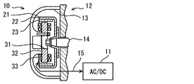
図1において、内燃機関用回転電機(以下、単に回転電機10という)は、発電機である。回転電機10は、整流回路(AC/DC)を含む電気回路11と電気的に接続されている。電気回路11は、単相の電力変換回路を提供する。回転電機10の用途の一例は、車両用の内燃機関12と連結される発電機である。回転電機10は、例えば、二輪車に利用することができる。
(First embodiment)
In FIG. 1, a rotating electrical machine for an internal combustion engine (hereinafter simply referred to as a rotating electrical machine 10) is a generator. The rotating
電気回路11は、回転電機10から出力される交流電力を整流し、バッテリを含む電気負荷に電力を供給する整流回路を提供する。電気回路11は、回転電機10から供給される点火制御用の基準位置信号を受信する信号処理回路を提供してもよい。電気回路11は、点火制御を実行する点火制御器を提供してもよい。
The
回転電機10は、内燃機関12に組み付けられている。内燃機関12は、ボディ13と、ボディ13に回転可能に支持され、内燃機関12と連動して回転する回転軸14とを有する。回転電機10は、ボディ13と回転軸14とに組み付けられている。ボディ13は、内燃機関12のクランクケース、ミッションケースなどの構造体である。回転軸14は、内燃機関12のクランク軸、またはクランク軸と連動する回転軸である。
The rotating
回転電機10は、アウタロータ型の回転電機である。回転電機10は、ロータ21と、ステータ31とを有する。以下の説明において、軸方向の語は、ロータ21、ステータ31、またはステータコア32を円筒と見なした場合の中心軸に沿う方向を指す。径方向の語は、ロータ21、ステータ31、またはステータコア32を円筒と見なした場合の径方向を指す。
The rotating
ロータ21は、界磁子である。ステータ31は、電機子である。ロータ21は、全体がカップ状である。ロータ21は、回転軸14の端部に接続されている。ロータ21は、回転軸14とともに回転する。ロータ21は、カップ状のロータコア22を有する。ロータコア22は、後述する永久磁石のためのヨークを提供する。ロータコア22は、磁性金属製である。ロータ21は、ロータコア22の内面に配置された永久磁石23を有する。ロータ21は、永久磁石23によって界磁を提供する。
The
ステータ31は、環状の部材である。ステータ31は、ロータ21と対向するように配置されている。ステータ31は、ステータコア32を有する。ステータコア32は、内燃機関12のボディ13に固定されている。ステータ31は、ステータコア32に巻回されたステータコイル33を有する。ステータコイル33は、電機子巻線を提供する。ステータコイル33は、単相巻線である。ステータコイル33を形成するコイル線は、絶縁被覆によって被覆された単線導体である。コイル線は、アルミニウムまたはアルミニウム合金のようなアルミ系金属製である。
The
回転電機10は、回転電機10と電気回路11との間における電気的な接続を提供するワイヤハーネス15を有する。ワイヤハーネス15は、複数の電線を含む。ワイヤハーネス15は、ステータコイル33と電気回路11とを接続する複数の電力線を含む。電気回路11は電力線が接続される外部回路である。電力線は、回転電機10が発電機として機能するとき、ステータコイル33に誘導される電力を電気回路11に供給する。
The rotating
図2において、ステータ31は、外突極型のステータである。ステータコア32は、複数の磁極32aを有する。磁極32aは、ティースとも呼ばれる部位である。ステータコア32とステータコイル33との間にはインシュレータ35が配置されている。インシュレータ35は、電気絶縁性の樹脂製である。インシュレータ35は、ステータ31上に設けられている。インシュレータ35は、ボビンとも呼ばれる。インシュレータ35の一部は、磁極32aに隣接して位置づけられることによって、ボビンのフランジ部を提供する。インシュレータ35の一部は、磁極32aの軸方向における両側に配置されている。以下の説明では、多くの場合、インシュレータ35は、ステータコア32の中央環状部に配置された環状の内側フランジ部と、中央環状部の軸方向表面の一部を覆うように広がる電極支持部とを指す。
In FIG. 2, a
ステータ31は、ステータコイル33の端部であるコイル端33aを、電気回路を形成するように接続するための接続部50を有する。接続部50は、コイル端33aと端子71とを接続する。接続部50は、ステータコイル33に含まれる複数のコイル線を接続するために、または、ステータコイル33を電力線に接続するために利用される。図示の例では、ステータ31は、2つの接続部50を有する。ひとつの接続部50は、ステータ31の一方端面上において、ひとつのコイル線とひとつの電極との接続を提供する。一方の電極は、ステータ31の他方の端面において電力線と接続されている。他方の電極は、ステータ31の他方の端面において他のコイル線のコイル端と接続されている。この実施形態では、電極は、ステータ31の一端面上と他端面上とに離れた接続部を提供する。
The
ステータコア32は、ステータコア32をボディ13に固定するための複数のボルト穴を有する。一群をなす2つの接続部50は、周方向に隣接する2つのボルト穴の間に配置されている。
The
接続部50は、コイル端33aおよびコイル端33aが接続される端子71を包む保護樹脂61を有する。図中には、コイル端33aおよび端子71を示すために、保護樹脂61で覆われる範囲が破線によって示されている。保護樹脂61は、電気絶縁性の樹脂である。保護樹脂61は、コイル端33aおよびコイル端33aの表面に密に付着している。保護樹脂61は、未硬化の状態で塗布、または滴下され、硬化されている。保護樹脂61は、ポッティング樹脂、または封止樹脂とも呼ばれる。
The
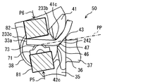
図3は、ステータ31上の一部、特に接続部50を拡大して示す拡大図である。図中には、コイル端33aと端子71とが接合された後の状態が図示されている。コイル端33aと端子71とを図示するために、保護樹脂61は図示されない。保護樹脂61の付与範囲が、破線によって示されている。
FIG. 3 is an enlarged view showing a part of the
インシュレータ35は、案内部36を有する。案内部36は、接続部50のためのコイル端33aを規定の形状に配置するために利用される。また、案内部36は、コイル端33aを規定の位置に保持するために利用される。案内部36は、ステータ31の端面において、軸方向に延び出す突部として形成されている。インシュレータ35は、ボビン部37を有する。ボビン部37は、磁極32aとステータコイル33との間に配置されている。ボビン部37は、磁極32aを囲む筒状である。図中には、ステータコイル33は図示されていない。
The
コイル端33aは、径方向外側から、内側へ向けて延びるように配置されている。コイル端33aは、ステータコイル33から案内部36を経由して端子71に隣接するように配置されている。コイル端33aは、やや湾曲している。コイル端33aは、端子71の面に沿うように、曲がっている。コイル端33aは、ステータ31の周方向に沿って延びる部分と、ステータ31の径方向に沿うように曲がる部分と、端子71の面に沿って延びる部分とを有する。
The
案内部36は、コイル端33aを収容することにより、端子71に向けてコイル端33aを案内する溝43を区画形成する。案内部36は、第1突部41と第2突部42とを有する。第1突部41と第2突部42とは、それらの間にコイル端33aを受け入れることができる溝43を区画形成する。第1突部41および第2突部42は、ステータ31の周方向に沿って細長く延びる壁によって提供されてもよい。
The
第1突部41は、コイル端33aの湾曲、すなわち曲げ部33bの内側に位置している。第1突部41は、コイル端33aの曲げ形状の内側への移動を制限する。第1突部41は、コイル端33aの曲げ形状を規定する。第1突部41は、内側突部とも呼ばれる。第1突部41は、コイル端33aと対向する壁面41aを提供する。壁面41aは、コイル端33aの湾曲形状を規定する曲面を有している。
The
第2突部42は、コイル端33aの湾曲、すなわち曲げ部33bの外側に位置している。第2突部42は、コイル端33aの曲げ形状の外側への移動を制限する。第2突部42は、外側突部とも呼ばれる。第2突部42は、コイル端33aと対向し、コイル端33aに接触する薄板部44を有する。薄板部44は、第2突部42の他の部位より薄い板状に形成されている。薄板部44は、第2突部42にのみ形成されている。第2突部42は、溝43の入口に設けられることなく、溝43の軸方向における奥にのみ設けられている。薄板部44は、コイル端33aの曲げ形状の外側からコイル端33aに接触することによってコイル端33aを保持している。
The
薄板部44の先端、すなわちコイル端33aとの接触部には、変形部45が形成されている。変形部45は、第2突部42に設けられている。変形部45は、後述の位置決め部47に設けられている。変形部45は、コイル端33aとの接触によって樹脂材料が変形することにより形成されている。変形部45は、樹脂材料の弾性変形、および/または塑性変形によって形成される。変形部45は、コイル端33aの移動を許容しながら、コイル端33aの過剰な移動を阻止する。例えば、薄板部44は、通常の製造方法におけるコイル端33aの移動によって変形するように形成されている。これに対して、第2突部42の他の部分は、通常の製造方法におけるコイル端33aの移動では、大きく変形しないように形成されている。このために、薄板部44は、第2突部42の他の部分よりも薄く、あるいは細く形成されている。変形部45の大きさは、各部の形状の誤差、配置位置のずれなどに起因して変化する。変形部45は、形成されない場合もある。
A
壁面41aとコイル端33aとの間には、隙間48が形成されている。隙間48の幅は、変形部45における変形量に相当する。隙間48の幅は、各部の形状の誤差、配置位置のずれなどに起因して変化する。隙間48は、形成されない場合もある。
A
インシュレータ35は、保護樹脂61の流出を抑制するための壁38を有する。案内部36と壁38とは、接続部50を囲むように配置されている。壁38により、保護樹脂61が流れ広がる範囲が制限される。壁38の軸方向の高さは、案内部36のそれより低い。壁38の軸方向の高さは、端子71のそれより低い。壁38により、保護樹脂61はコイル端33aおよび端子71の周囲に厚く付与される。
The
端子71は、板状である。端子71は、その面が径方向に沿って広がるように配置されている。言い換えると、端子71は、周方向に開閉される溶接用の一対の電極の間に挟むことができるように配置されている。端子71は、板状の電極72の一部に設けられている。図示の例では、電極72は、ステータ31の両端面に突出する両端を有する。端子71は、電極72の端部に形成されている。電極72は、インシュレータ35にインサート成形されるか、または差し込まれることによってインシュレータ35によって支持されている。電極72は、バスバーとも呼ばれる。電極72の他端は、他のコイル端、または電力線と接続されている。
The terminal 71 is plate-shaped. The terminal 71 is arranged so that its surface extends along the radial direction. In other words, the terminal 71 is arrange | positioned so that it can be pinched | interposed between a pair of electrodes for welding opened and closed in the circumferential direction. The terminal 71 is provided on a part of the plate-
端子71は、溶接に適した形状を有する。例えば、端子71は、コイル端33aと交差する稜線をもつ突部73を有する。突部73は、軸方向に沿って延びる突条である。端子71は、アルミ系金属製のコイル端33aとの溶接に適した金属製である。端子71は、溶接端子とも呼ばれる。端子71は、インシュレータ35に支持されている。端子71は、ステータ31の軸方向に沿って延び出すように支持されている。
The terminal 71 has a shape suitable for welding. For example, the terminal 71 has a
コイル端33aと端子71とは、電気抵抗溶接、またはスポット溶接によって溶接され、電気的に、かつ機械的に接合されている。コイル端33aと端子71との間には、これら両者の金属が一旦は溶融し、再び硬化することによって形成された溶接部51が形成されている。溶接部51は、溶接痕とも呼ばれる。接続部50の中に配置された端子71とコイル端33aとは、金属が露出した表面を有している。
The
溶接前におけるコイル端33aの断面形状は、円形である。溶接後のコイル端33aの断面形状は、やや扁平な形である。溶接工程においてコイル端33aと端子71とは溶接用の電極によって挟まれる。コイル端33aおよび端子71は、溶接のための圧縮、および溶接に伴う溶融によって、やや変形している。コイル端33aは、溶接用電極との接触痕である平面部分を有する場合がある。コイル端33aは、端子71との接触部分において、突部73に沿うように変形している。突部73もまた、変形している。コイル端33aの断面形状は、ステータ31の軸方向に長軸を有する楕円状または長円状である。コイル端33aは、端子71の板状の表面に沿うように位置づけられている。コイル端33aは、その長手方向が、突部73の長手方向と交差するように配置されている。コイル端33aは、その表面が、突部73の頂部、突部73の両斜面、および端子71の平面部と接触するように配置されている。これにより、コイル端33aと端子71との間は、強固に接合される。
The cross-sectional shape of the
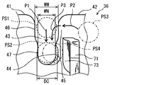
図4は、案内部36を示す。図中において、破線、および一点鎖線は、コイル端33aを示す。太い実線の矢印は、製造方法におけるコイル端33aの移動経路を示す。
FIG. 4 shows the
溝43は、多様な機能を提供する。溝43は、製造方法において、コイル端33aを規定の位置に向けて案内する案内溝を提供する。溝43は、製造方法におけるコイル端33aと端子71とが溶接される前の段階において、コイル端33aを規定の位置に保持する保持溝を提供する。溝43は、製造方法において、コイル端33aを規定の位置範囲内に位置付けながら、コイル端33aと端子71との望ましい溶接を可能とするためのコイル端33aの僅かな移動を許容する溶接支援部を提供する。溶接支援部としての機能は、溝43の形状が変形すること、すなわち溝43を区画形成する第1突部41および第2突部42の変形により提供される。より具体的には、溶接支援部としての機能は、薄板部44の変形によって提供される。溝43は、回転電機10として製造された後において、コイル端33aの過剰な移動を抑制する移動抑制部を提供する。回転電機10の製造方法は、ステータコイル33およびコイル端33aを接着剤、すなわち樹脂によって接着し、固定する工程を含む場合がある。この場合、溝43は、接着剤を溜める機能、および接着剤の過剰な広がりを阻止するように接着剤を留める部分としても機能する。この場合、溝43およびその中の薄板部44および変形部45による緩い保持は、接着剤との協働によって強固な固定となる。
The
溝43は、コイル端33aを溝43の中に受け入れるための入口部46を有する。入口部46は、コイル端33aを受け入れ可能な幅WWを有する。入口部46の幅WWは、コイル端33aの直径DCより大きい。入口部46は、ステータ31の軸方向に沿ってコイル端33aの直径DC以上の深さをもつ。入口部46は、その中にコイル端33aを緩く保持するために、DC/2を上回る深さを有することが望ましい。入口部46は、ステータ31の軸方向に沿って操作されるコイル端33aを、溝43の底に向けて案内する。入口部46は、製造方法において、コイル端33aを一時的に位置付けるために利用される。入口部46は、開口部、あるいは幅広部とも呼ばれる。
The
溝43は、位置決め部47を有する。位置決め部47は、溝43の底部に設けられている。位置決め部47は、ステータ31の軸方向における、コイル端33aが最終的に位置づけられる規定の位置に設けられている。位置決め部47は、ステータ31の軸方向に沿ってコイル端33aの直径DC以上の深さをもつ。位置決め部47は、その中にコイル端33aを安定的に保持するために、DC/2を上回る深さを有することが望ましい。位置決め部47の少なくとも一部は、薄板部44によって区画形成されている。入口部46と位置決め部47との間には、斜面が設けられている。斜面は、入口部46と位置決め部47とを滑らかにつないでいる。斜面は、滑らかなコイル端33aの圧入を可能とする。
The
位置決め部47は、第1突部41および第2突部42が変形することによってコイル端33aを受け入れ可能な幅WNを有する。位置決め部47の幅WNは、コイル端33aの直径DCより小さい。位置決め部47の幅WNは、コイル端33aの直径DC以下に設定されてもよい。位置決め部47の幅WNは、入口部46の幅WWより小さい。位置決め部47は、ステータ31の軸方向に沿って操作されるコイル端33aを、第1突部41および第2突部42が変形しながら、受け入れる。位置決め部47は、コイル端33aと接触することにより変形している。コイル端33aは、位置決め部47の中に圧入されているともいえる。変形は、主として薄板部44の変形である。位置決め部47は、底部、あるいは幅狭部とも呼ばれる。
The positioning
位置決め部47は、コイル端33aが破線で示される位置PS1から位置PS2へ操作されるときに変形する。この変形は、弾性変形、または塑性変形によって提供される。このとき、位置決め部47によるコイル端33aの保持は、堅い保持である。位置決め部47は、溶接工程におけるコイル端33aの移動によって、さらに変形することがある。この変形は、薄板部44の変形によって提供される。この変形により、薄板部44には、変形部45が形成されることがある。変形部45が形成される場合、位置決め部47によるコイル端33aの保持は、堅い保持から、緩い保持へと変化している。このとき、位置決め部47は、コイル端33aが位置づけられている部位においてコイル端33aと接触することにより変形してコイル端33aの直径DC以上の幅を提供している部分を有する。さらに、位置決め部47は、コイル端33aの直径DCより小さい幅WNの部分を有する。
The positioning
コイル端33aは、溝43内において、位置PS2に位置づけられる。さらに、コイル端33aは、端子71と接触する部位において、一点鎖線で示される位置PS3から位置PS4へ操作され、位置PS4に位置づけられる。なお、図中には、溶接前におけるコイル端33aの位置が図示されている。
The
回転電機10の製造方法は、ロータ21を製造する工程、ステータ31を製造する工程、およびロータ21とステータ31とを内燃機関12に装着する工程とを含む。
The method for manufacturing the rotating
ステータ31を製造する工程は、コイル端33aと端子71とが正規の位置に配置されるようにステータ31を組み立てる工程を含む。この工程では、ステータコア32にインシュレータ35およびステータコイル33が装着される。この工程において、電極72がステータ31上に固定される。
The step of manufacturing the
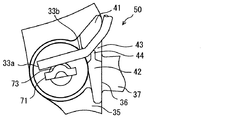
ステータ31を製造する工程は、コイル端33aと端子71とを正規の位置に配置する工程を含む。正規の位置は、コイル端33aを端子71に溶接する直前の位置である。図4、図5、図6に図示されるように、コイル端33aは、溝43内に挿入され、端子71と接触するように曲げられる。コイル端33aの操作は、作業者による手作業、または、組立機による機械化された工具の動きによって提供される。
The process of manufacturing the
図4において矢印P1で図示されるように、コイル端33aは、溝43内を軸方向に移動するように操作される。コイル端33aは、溝43の外から、溝43の中に挿入される。これにより、入口部46にコイル端33aを緩く位置付ける工程が提供される。ここでは、コイル端33aは、入口部46の中でコイル端33aの径方向へ入口部46で規制された範囲内で移動可能である。コイル端33aは、コイル端33aの軸方向へもわずかに移動可能である。
As shown by the arrow P1 in FIG. 4, the
さらに、コイル端33aは、破線で示される位置PS1から、位置PS2へ押し込まれる。これにより、位置決め部47に向けて、入口部46を経由してコイル端33aを移動させる工程が提供される。このとき、薄板部44は、少なくとも弾性変形する。この実施形態では、薄板部44の一部は塑性変形する。この結果、コイル端33aは、樹脂材料の弾性を利用して、溝43内において堅く保持される。堅い保持は、きつい締め付けでもある。これにより、位置決め部47においてコイル端33aと案内部36とを接触させることにより、案内部36を変形させコイル端33aを堅く位置付ける工程が提供される。ただし、薄板部44は、コイル端33aが延在する方向、すなわち径方向に関して薄く形成されている。よって、薄板部44は、第1突部41、および第2突部42の他の部位よりも変形しやすい。また、コイル端33aと薄板部44との接触面積は小さいから、薄板部44が提供する摩擦力は第2突部42の厚さによる摩擦力より小さく調節されている。
Further,
図4において矢印P2、P3で図示されるように、コイル端33aは、溝43の外において、端子71の上から、端子71の面の上に向けて移動するように操作される。コイル端33aの先端は、溝43から延び出し、その先端部は一点鎖線で図示される位置PS3に位置づけられる。コイル端33aは、端子71の上を経由して、突部73の上に接するように、操作される。このとき、コイル端33aは、曲げられる。
As illustrated by arrows P2 and P3 in FIG. 4, the coil end 33 a is operated so as to move from the top of the terminal 71 toward the surface of the terminal 71 outside the
図5には、矢印P1で示される操作によってコイル端33aが溝43内に配置された状態が実線で図示されている。コイル端33aは、溝43の上から矢印P1で示されるように溝43内に配置される。
In FIG. 5, a state in which the coil end 33 a is disposed in the
コイル端33aのうち、溝43から延び出す部分は、矢印P2で示されるように操作される。すなわち、コイル端33aは、端子71の上を経由して曲げられる。このとき、コイル端33aは、第1突部41を内型として曲げられる。これに代えて、コイル端33aは、第1突部41とは異なる部材を内型として曲げられてもよい。コイル端33aは、破線で示されるように曲げられる。コイル端33aには、曲げ部33bが形成される。曲げ部33bは、コイル端33aが端子71に沿うように曲がっている。
A portion of the
次に、コイル端33aは、矢印尾部P3で示されるように、突部73の突出方向に関して突部73の頂部の上に接するように、ステータ31の軸方向に沿って押し込むように操作される。これにより、コイル端33aは、端子71の面の上に、すなわちステータ31の軸方向に対して突部73の横に位置づけられる。
Next, the
上述の矢印P1、P2、P3で示される操作は、同時に、並行的に行われてもよい。また、矢印P1、P2、P3の順で行われてもよい。例えば、矢印P1の操作によってコイル端33aを溝43内に徐々に押し込みながら、矢印P2の操作と、矢印P3の操作とを順に実行してもよい。
The operations indicated by the arrows P1, P2, and P3 described above may be performed simultaneously in parallel. Moreover, you may carry out in order of arrow P1, P2, and P3. For example, the operation of the arrow P2 and the operation of the arrow P3 may be sequentially performed while the
図6は、コイル端33aが正規の位置に位置付けられた状態を示す。この状態は、溶接前の状態である。コイル端33aは、第1突部41と薄板部44との間に堅く保持されている。コイル端33aは、曲げ部33bから真っ直ぐに延びている。コイル端33aの外周面は、突部73の上に接触している。コイル端33aは、案内部36による保持と、コイル端33a自身の弾性とによって規定の位置に保持されている。
FIG. 6 shows a state where the
ステータ31を製造する工程は、コイル端33aと端子71とを電気的に接続する工程を含む。この工程は、位置決め部47によってコイル端33aを位置づけた状態で、コイル端33aと端子71とを接続する工程である。この工程は、電極81、82によってコイル端33aと端子71とを挟み、コイル端33aと端子71とを溶接する工程でもある。この工程は、接合工程、または溶接工程と呼ばれる。この工程は、コイル端33aと端子71とを一対の溶接電極によって挟む工程と、溶接電極に通電することによってコイル端33aと端子71とを溶接する工程と、溶接電極を取り除く工程とを含む。この工程は、コイル端33aと端子71との溶接状態を検査する工程を含むことができる。
The step of manufacturing the
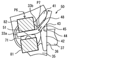
図7は、コイル端33aと端子71とが溶接電極81、82によって挟まれる初期の段階を示す。電極81は、矢印P5で示されるように操作され、端子71に接触する。電極82は、矢印P6で示されるように操作され、コイル端33aに接触する。このとき、コイル端33aの傾きなどに起因して、コイル端33aと電極82とが平行に接触しないことがある。
FIG. 7 shows an initial stage in which the coil end 33 a and the terminal 71 are sandwiched between the
例えば、図示されるように、電極82の角が、案内部36と突部73との間に架け渡されたコイル端33aの懸架部分に接触する。この実施形態では、案内部36の形状、およびコイル端33aを曲げる工程の両方が、図示されるコイル端33aの形状を提供するように設定されている。コイル端33aは、その懸架部分が、仮想平面PPを越えて端子71側に位置しないように配置され、曲げられている。仮想平面PPは、端子71の面に平行であって、突部73の突出方向における頂部に接する平面である。この仮想平面PPは、端子71を挟もうとする電極81、82の表面とも平行である。
For example, as shown in the figure, the corner of the
案内部36は、コイル端33aが図示される形状に配置されるように形成されている。すなわち、ステータ31の径方向内側における溝43の縁41c、42cは、それらの両方が、仮想平面PPに対して端子71とは反対側に位置づけられている。言い換えると、溝43の径方向内側の縁41c、42cのうち、コイル端33aの曲げの外側に位置する縁42cは、仮想平面PPに接するように、または仮想平面PPよりも電極82側に位置づけられている。なお、縁41cは、第1突部41によって提供されている。縁42cは、第2突部42によって提供されている。この結果、コイル端33aは、縁41c、42cから、端子71および仮想平面PPに向けて近づくように延び出し、端子71に到達する。コイル端33aを曲げる工程では、コイル端33aは、縁41c、42cから端子71に向けて真っ直ぐに延びるように曲げられる。
The
電極82が矢印P6に沿って操作されると、電極82は、接触部33cにおいてコイル端33aに最初に接触し、接触部33cを押す。この結果、コイル端33aは、端子71に向けて平行に押し付けられるだけでなく、端子71に沿うように回動する。
When the
このとき、コイル端33aは、適正な溶接部を形成するためには望ましくない移動をする場合がある。例えば、コイル端33aの懸架部分の一端は、案内部36で保持されているから、コイル端33aは突部73の上を滑るように移動することがある。このような移動は、溶接工程における溶融部分の移動を生じることがあり、適正量の溶融を妨げることがある。また、溶融部分が適正位置からはみ出すことがある。
At this time, the
図8は、電極82によるコイル端33aの移動を示している。電極82は、矢印P6のように操作される。一対の電極81、82の間に挟まれたコイル端33aと端子71とは、溶接の進行にともなって溶接部51を形成する。
FIG. 8 shows the movement of the coil end 33 a by the
この過程において、コイル端33aは、端子71に接触するために、矢印P7の方向へ引き込まれる。このとき、薄板部44は、比較的小さい摩擦力でコイル端33aを保持しているから、コイル端33aが矢印P7の方向へ引き込まれることを許容する。
In this process, the
さらに、矢印P7へ示される力の分力は、薄板部44を変形させ、変形部45を形成する。変形部45は、コイル端33aとの接触部に形成されるから、薄板部44は軸方向に関してコイル端33aを保持し続ける。これにより、コイル端33aは、第1突部41から離れ、隙間48が形成される。このような薄板部44の変形も、コイル端33aの移動を許容する。この工程は、電極81、82によってコイル端33aと端子71とが挟まれるときに、コイル端33aの移動によって案内部36がさらに変形することによりコイル端33aの移動を許容する工程である。
Further, the force component indicated by the arrow P <b> 7 deforms the
第1突部41および第2突部42は、コイル端33aが矢印P7に沿って引き込まれた後も、ステータ31の周方向、および軸方向におけるコイル端33aの過剰な移動を抑制する。第1突部41および第2突部42は、薄板部44が変形した後も、ステータ31の周方向、および軸方向におけるコイル端33aの過剰な移動を抑制する。
The
このように、案内部36、特に薄板部44は、溶接のための工程の初期まではコイル端33aを堅く保持する。薄板部44は、溶接のための工程の中で、コイル端33aの移動を許容する。この結果、コイル端33aは、端子71の上を引きずられるように移動することなく、図示される溶接状態に移行する。コイル端33aは、突部73の上においてコイル端33aの長さ方向にずれることなく、端子71と溶接される。
Thus, the
ステータ31を製造する工程は、保護樹脂61を付与する工程を含む。保護樹脂61により、コイル端33aおよび端子71が包まれる。保護樹脂61は、接続部50内に配置されたコイル端33aおよび端子71の露出した金属面を完全に覆うように付与される。保護樹脂61は、少なくとも、コイル端33aのうちの保護皮膜が除去されることによって露出した金属面、および端子71の露出した金属面を覆う。保護樹脂61は、未硬化の状態で付与される。この後、保護樹脂61は、硬化する。
The step of manufacturing the
保護樹脂61は、コイル端33aおよび端子71を他の部材から電気的に絶縁するための絶縁保護を提供する。保護樹脂61は、さらに、コイル端33aおよび端子71の腐蝕を抑制するための耐蝕保護を提供する。耐蝕保護により、アルミ系金属製のコイル端33aが利用可能となっている。さらに、耐蝕保護により、アルミ系金属製のコイル端33aと、鉄系金属製の端子71との溶接が利用可能となっている。
The
保護樹脂61は、コイル端33aおよび端子71と、他の部材との直接的な接触を阻止する。回転電機10が空冷される場合、保護樹脂61は、コイル端33aおよび端子71を、液体、および泥などの異物から保護する。回転電機10が内燃機関12の潤滑油収容空間に配置される場合、保護樹脂61は、コイル端33aおよび端子71を、潤滑油の中の金属粉から保護する。
The
保護樹脂61は、振動に対してコイル端33aおよび端子71の接続を維持するように貢献する。保護樹脂61は、コイル端33aと端子71とに接触するだけでなく、インシュレータ35にも接触する。保護樹脂61は、コイル端33a、端子71、およびインシュレータ35の間を埋める。これにより、コイル端33a、端子71、およびインシュレータ35の移動、変形が抑制される。この実施形態では、比較的移動しやすいコイル端33aと、比較的強固に固定された端子71とが接続されるが、保護樹脂61は、それらの間の接続を維持するために貢献する。また、溶接などの接続工法によってコイル端33aおよび端子71に変形があっても、それらを補強し、それらの接続を維持するために貢献する。
The
ステータ31を製造する工程は、さらに、他の接続工程を含む。この工程には、電極72と電力線とを接続する工程、または電極72と他のコイル端とを接続する工程を含むことができる。
The process of manufacturing the
以上に述べた実施形態によると、溝43には、入口部46と位置決め部47とが設けられている。この結果、入口部46を利用してコイル端33aを位置決め部47へ挿入することができる。これにより、位置決め部47は、望ましい接続状態の形成に適したコイル端33aの案内を提供するように形成することができる。
According to the embodiment described above, the
位置決め部47は、溶接工程においてコイル端33aの移動を許容する。このため、端子71の上におけるコイル端33aのすべり移動が抑制される。この結果、コイル端33aと端子71との間に望ましい接続状態が形成される。
The
位置決め部47は、溶接工程において変形した変形部45においてコイル端33aを保持している。よって、位置決め部47は変形部45が形成される前はコイル端33aを堅く保持し、変形部45が形成された後はコイル端33aを緩く保持する。これにより、コイル端33aと端子71とを挟むことによってそれらを溶接する工程において、位置決め部47はコイル端33aの移動を許容することができる。このため、端子71の上におけるコイル端33aのすべり移動が抑制される。この結果、コイル端33aと端子71との間に望ましい接続状態が形成される。
The
(第2実施形態)
この実施形態は、先行する実施形態を基礎的形態とする変形例である。上記実施形態では、位置決め部47は、コイル端33aを緩く保持するように変形することができる。これに代えて、この実施形態では、位置決め部47を提供する案内部36は、コイル端33aを堅く保持し続ける。
(Second Embodiment)
This embodiment is a modification based on the preceding embodiment. In the above embodiment, the positioning
図9および図10は、この実施形態における案内部36を示す斜視図である。図11、図12、図13は、この実施形態における、コイル端33aと端子71とを電気的に接続する工程を示す。
9 and 10 are perspective views showing the
この実施形態でも、案内部36は、第1突部41と第2突部242とを有する。第2突部242は、先行する実施形態における薄板部44および変形部45を備えない。第2突部242は、その径方向の厚さのほぼ全体で、コイル端33aと接触している。この実施形態でも、第1突部41と第2突部242とは、溝43を区画形成する。溝43は、入口部46と位置決め部47とを有する。位置決め部47は、第2突部242の厚さのほぼ全体でコイル端33aを保持する。
Also in this embodiment, the
図11には、溶接工程の初期段階が図示されている。この実施形態では、コイル端33aは溝43内において堅く保持されている。しかも、接合工程の前においても、後においても、コイル端33aは溝43内において堅く保持されている。
FIG. 11 shows the initial stage of the welding process. In this embodiment, the coil end 33 a is firmly held in the
電極81、82は、コイル端33aと端子71とに接触するようにそれぞれ操作される。このとき、この実施形態では、コイル端33aのうち、突部73より径方向内側に突出する自由端部分が、電極82と接触する。電極82は、接触部233cに最初に接触する。接触部233cは、コイル端33aの突出する自由端部分に位置している。
The
この実施形態では、自由端部分に接触部233cが位置するようにコイル端33aが曲げられている。別の観点では、自由端部分に接触部233cが位置するように案内部36の形状と、突部73の位置とが設定されている。コイル端33aは、端子71の上において、コイル端33aの先端に向かうほど端子71から離れるように配置されている。
In this embodiment, the
この実施形態では、案内部36の形状、およびコイル端33aを曲げる工程の両方が、図示されるコイル端33aの形状を提供するように設定されている。コイル端33aは、その懸架部分の一部が、仮想平面PPを越えて端子71側に位置するように配置され、曲げられている。
In this embodiment, both the shape of the
案内部36は、コイル端33aが図示される形状に配置されるように形成されている。すなわち、縁42cは、仮想平面PPに対して端子71側に位置づけられている。言い換えると、溝43の径方向内側の縁41c、42cのうち、コイル端33aの曲げの外側に位置する縁42cは、仮想平面PPよりも端子71側に位置づけられている。この結果、コイル端33aは、縁41c、42cから、仮想平面PPを越えて端子71側を経由した後に、突部73の上に戻るように延び出している。コイル端33aを曲げる工程では、コイル端33aは、縁41c、42cから、仮想平面PPを越えて端子71側を経由するように曲げられる。
The
この実施形態では、この配置を提供するように、コイル端33aを曲げる工程が採用される。このようなコイル端33aの配置が、自由端部分に接触部233cを形成することを可能とする。
In this embodiment, a step of bending the
図12には、電極82が徐々に押し付けられる段階が図示されている。コイル端33aは、端子71に沿うように徐々に変形する。コイル端33aは、その自由端部分から、すなわち先端から、徐々に変形する。よって、コイル端33aは、突部73との接触を一定の部分において維持しながら、端子71に接触してゆく。
FIG. 12 illustrates a stage where the
図13には、溶接工程の終期段階が図示されている。電極82は、規定の終了位置にまで押し付けられている。コイル端33aは、端子71に溶接されている。
FIG. 13 shows the final stage of the welding process. The
この実施形態によると、入口部46を利用してコイル端33aを位置決め部47へ挿入することができる。これにより、位置決め部47は、望ましい接続状態の形成に適したコイル端33aの案内を提供するように形成することができる。
According to this embodiment, the coil end 33 a can be inserted into the
案内部36は、コイル端33aを堅く保持する。しかも、コイル端33aと電極82とは、電極82がコイル端33aの自由端部分に接触するように配置される。電極82とコイル端33aとは、コイル端33aの先端寄りの部位において最初に接触する。言い換えると、コイル端33aの懸架部分の上に接触部33cが形成されることが回避される。これにより、コイル端33aが端子71の上、特に突部73の受けを滑るようにして移動することが抑制される。懸架部分が押される場合に比べて、コイル端33aが端子71の上を滑るように移動することが抑制される。これにより、コイル端33aと端子71との間に望ましい接続状態が形成される。
The
(第3実施形態)
この実施形態は、先行する実施形態を基礎的形態とする変形例である。この実施形態では、コイル端33aの端子71上での移動を抑制するように、コイル端33aの曲げ部33bが利用される。
(Third embodiment)
This embodiment is a modification based on the preceding embodiment. In this embodiment, the
図14および図15は、この実施形態における、コイル端33aと端子71とを電気的に接続する工程を示す。この実施形態でも、コイル端33aは、案内部36によって案内され、保持されている。コイル端33aは、第1突部41と、第2突部342との間に押し込まれ、堅く保持されている。第2突部342は、製造工程においてコイル端33aに作用する力では変形しないように形成されている。この実施形態でも、第1突部41と第2突部342との間には溝43が形成されている。溝43は、入口部46と位置決め部47とを有する。
14 and 15 show a process of electrically connecting the
コイル端33aは、案内部36から端子71に向けて延び出す部分に、曲げ部33bを含むS字状の曲げ部333dを有する。ここでは、S字状の語は、逆S字状を含むものとして定義される。曲げ部333dは、コイル端33aを端子71に近づく方向にやや迂回させる。曲げ部333dは、コイル端33aを端子71に対して望ましい位置関係となるように配置することを可能とする。コイル端33aは、端子71の上において、コイル端33aの先端に向かうほど端子71から離れるように配置されている。このような、先端開きの配置は、曲げ部333dによって提供されている。先端開きの配置は、第2実施形態と同様に、コイル端33aの自由端部分に、接触部233cを位置付けることを可能とする。
The
別の観点では、曲げ部333dは、コイル端33aの中の曲がりやすい部分として形成されている。曲げ部333dは、案内部36と突部73との間に架け渡されたコイル端33aの懸架部分に、曲げ部33bだけが形成されている場合よりも、コイル端33aを曲がりやすくするための部分として形成されている。曲げ部333dは、その曲げ部333d自身が変形することによって、曲げ部333dより先のコイル端33aが、端子71に沿うように回動することを許容する。言い換えると、曲げ部333dは、それ自身が変形することによって、コイル端33aが突部73の上を滑るように移動することを阻止する。
From another viewpoint, the
曲げ部333dは、案内部36と突部73との間においてコイル端33aを弛ませて形成された、たるみ部とも呼ぶことができる。この実施形態では、案内部36と端子71との間のコイル端33aの懸架部分にたるみを形成するようにコイル端33aを曲げる工程が採用されている。
The
この実施形態では、案内部36の形状、およびコイル端33aを曲げる工程の両方が、図示されるコイル端33aの形状を提供するように設定されている。コイル端33aは、その懸架部分の一部、すなわち曲げ部333dの一部が、仮想平面PPを越えて端子71側に位置するように配置され、曲げられている。
In this embodiment, both the shape of the
案内部36は、コイル端33aが図示される形状に配置されるように形成されている。縁42cは、仮想平面PPに対して電極82側、すなわち、仮想平面PPに対して突部73の突出方向の側に位置づけられている。言い換えると、溝43の径方向内側の縁41c、42cは、それら両方が、仮想平面PPに対して端子71とは反対側に位置づけられている。さらに、案内部36は、案内部36と端子71との間に、曲げ部333dを形成するために必要な空間を提供するように、端子71からステータ31の径方向外側に離れるように形成されている。コイル端33aを曲げる工程では、コイル端33aは、縁41c、42cから、仮想平面PPを越えて端子71側を経由するように曲げられる。言い換えると、コイル端33aは、縁41c、42cから、蛇行するように曲げられる。
The
この実施形態でも、電極82は、自由端部分の接触部233cに、まず最初に接触する。電極82は、コイル端33aを端子71に向けて押し付ける。これにより、コイル端33aは、端子71に沿うように変形する。このとき、曲げ部333dは、曲げ部333dより先端側のコイル端33aが端子71に沿うように回動することを許容する。曲げ部333dは、コイル端33aの中のヒンジ部分として機能する。この実施形態でも、電極82が、突部73と案内部36との間に架け渡されたコイル端33aの懸架部分にだけ接触することはない。案内部36と端子71との間に架け渡されたコイル端33aの懸架部分が押される場合に比べて、コイル端33aが端子71の上を滑るように移動することが抑制される。これにより、望ましい溶接部が形成される。
Also in this embodiment, the
この実施形態によると、コイル端33aは、溶接の前は堅く位置づけられている。案内部36と端子71との間に架け渡されたコイル端の懸架部分には、たるみが形成されている。溶接工程においてコイル端33aが電極81、82で押される。よって、コイル端33aは、端子71に沿うように回動しようとする。このとき、たるみが変形する。たるみの変形によって、コイル端33aが端子71の上を滑るように移動することが抑制される。これにより、望ましい溶接部が形成される。
According to this embodiment, the
(第4実施形態)
この実施形態は、先行する実施形態を基礎的形態とする変形例である。先行する実施形態に代えて、多様な形状の溝43を採用することができる。図16は、この実施形態の溝43を示す。溝43は、ステータ31の軸方向と平行な一対の縁によって区画された四角形の入口部446を有する。この実施形態でも、入口部446によりコイル端33aを案内することができる。
(Fourth embodiment)
This embodiment is a modification based on the preceding embodiment. Instead of the preceding embodiment, various shapes of
(第5実施形態)
この実施形態は、先行する実施形態を基礎的形態とする変形例である。図17は、この実施形態の溝43を示す。溝43は、ステータ31の軸方向に対して傾斜する一対の縁によって区画された三角形、または台形と呼びうる入口部546を有する。この実施形態でも、入口部546によりコイル端33aを案内することができる。
(Fifth embodiment)
This embodiment is a modification based on the preceding embodiment. FIG. 17 shows the
(第6実施形態)
この実施形態は、先行する実施形態を基礎的形態とする変形例である。図18は、この実施形態の溝43を示す。溝43は、軸方向と平行なひとつの縁と、軸方向に対して傾斜するひとつの縁とによって区画された入口部646を有する。この実施形態でも、入口部646によりコイル端33aを案内することができる。
(Sixth embodiment)
This embodiment is a modification based on the preceding embodiment. FIG. 18 shows the
(第7実施形態)
この実施形態は、先行する実施形態を基礎的形態とする変形例である。先行する実施形態では、単相コイルのための電極72が例示されている。これに代えて、先行する実施形態に採用された案内部36の構成は、多様な用途の電極に適用することができる。
(Seventh embodiment)
This embodiment is a modification based on the preceding embodiment. In the preceding embodiment, an
図19は、この実施形態のステータ31をモデル化した断面図である。この実施形態では、三相コイルのための電極72、775が図示されている。複数の電極72、775は、その面がほぼ周方向に広がるように配置されている。複数の電極72、775は、ステータ31の径方向に沿って開閉可能な溶接用の電極によって挟むことができるように配置されている。
FIG. 19 is a cross-sectional view modeling the
電極72は、コイル端33aとワイヤハーネス15の電力線とを接続する。電極72は、端子71と端子74とを有する。電極72は、ステータ31を軸方向に貫通する貫通電極である。電極72は、ステータ31の両面に互いに隔離された端子71、74を有する。
The
電極775は、三相コイルのための中性点接続を提供する。電極775は、複数の端子71を有する。電極775は、E字型の多頭電極である。この実施形態においても、案内部36は、先行する実施形態と同じ構造を採用することができる。
(第8実施形態)
この実施形態は、先行する実施形態を基礎的形態とする変形例である。この実施形態では、他の電極875、872が例示されている。
(Eighth embodiment)
This embodiment is a modification based on the preceding embodiment. In this embodiment,
図20は、この実施形態のステータ31をモデル化した断面図である。この実施形態では、三相コイルのための電極872、875が図示されている。複数の電極872、875は、その面がほぼ径方向に広がるように配置されている。複数の電極872、875は、ステータ31の周方向に沿って開閉可能な溶接用の電極によって挟むことができるように配置されている。
FIG. 20 is a cross-sectional view modeling the
電極872は、コイル端33aとワイヤハーネス15の電力線とを接続する。電極872は、L字状の板である。電極872は、端子71と端子874とを有する。電極872は、ステータ31を貫通しない非貫通電極である。電極872は、その一端にインシュレータ35への固定部を有する。電極872は、その他端に、電力線と接続される端子874を有する。電極872は、端子874と固定部との間に、端子71を有する。
The
複数の電極875は、三相コイルのための中性点接続を提供する。複数の電極875は、互いに電気的に独立してインシュレータ35に設けられている。それぞれの電極875は、コイル端33aと接続される端子71と、電極878と接続される端子877とを有する。電極875は、一端にインシュレータ35への固定部を有し、他端に端子877を有する。端子71は、電極875の長さ方向の中央部に設けられている。電極875は、I字状の板である。
A plurality of
電極878は、複数の電極875に接続される共通の電極である。電極878は、導体片、または電線によって提供することができる。電極875と電極878とは、はんだ付けによって電気的に、かつ機械的に接続される。この実施形態においても、案内部36は、先行する実施形態と同じ構造を採用することができる。
The
(他の実施形態)
この明細書の開示は、例示された実施形態に制限されない。開示は、例示された実施形態と、それらに基づく当業者による変形態様を包含する。例えば、開示は、実施形態において示された部品および/または要素の組み合わせに限定されない。開示は、多様な組み合わせによって実施可能である。開示は、実施形態に追加可能な追加的な部分をもつことができる。開示は、実施形態の部品および/または要素が省略されたものを包含する。開示は、ひとつの実施形態と他の実施形態との間における部品および/または要素の置き換え、または組み合わせを包含する。開示される技術的範囲は、実施形態の記載に限定されない。開示されるいくつかの技術的範囲は、特許請求の範囲の記載によって示され、さらに特許請求の範囲の記載と均等の意味及び範囲内での全ての変更を含むものと解されるべきである。
(Other embodiments)
The disclosure of this specification is not limited to the illustrated embodiments. The disclosure encompasses the illustrated embodiments and variations by those skilled in the art based thereon. For example, the disclosure is not limited to the combinations of parts and / or elements shown in the embodiments. The disclosure can be implemented in various combinations. The disclosure may have additional parts that can be added to the embodiments. The disclosure includes those in which parts and / or elements of the embodiments are omitted. The disclosure encompasses the replacement or combination of parts and / or elements between one embodiment and another. The technical scope disclosed is not limited to the description of the embodiments. Some technical scope disclosed is indicated by the description of the claims, and should be understood to include all modifications within the meaning and scope equivalent to the description of the claims. .
上記実施形態では、コイル端33aと端子71とは、電気抵抗溶接、またはスポット溶接によって溶接されている。これに代えて、コイル端33aと端子71とは、ハンダによる接合、または部材を機械的に変形させて接合するかしめによって接合されてもよい。
In the said embodiment, the
上記実施形態では、回転電機10は、発電機である。これに代えて、ここに開示される接続部の構造は、発電電動機、または交流発電機スタータ(AC Generator Starter)と呼ばれる回転電機の接続部に適用されてもよい。この場合、回転電機10は、多相のステータコイル33を有する。例えば、三相のステータコイル33は、発電機として機能するときに三相交流電力を出力する。三相のステータコイル33は、三相交流電力を供給されることによって、電動機として機能する。電気回路11は、インバータ回路(INV)と制御装置(ECU)とを備えることができる。回転電機10は、電動機制御のための回転位置センサと、点火制御のための回転位置センサとを含むことがある。このような適用に関して、特開2013−233030号公報、特開2013−27252号公報、または特許第5064279号に記載の内容が参照により援用される。
In the said embodiment, the rotary
上記実施形態では、案内部36は、インシュレータ35の樹脂材料によって一体的に形成されている。これに代えて、インシュレータ35とは別体の樹脂材料によって案内部36を形成してもよい。この場合、案内部36は、ステータコア32またはインシュレータ35に差し込まれるなどの連結機構を介して連結される。
In the above embodiment, the
10 回転電機、11 電気回路、12 内燃機関、13 ボディ、
14 回転軸、15 ワイヤハーネス、21 ロータ、22 ロータコア、
23 永久磁石、31 ステータ、32 ステーアコア、32a 磁極、
33 ステータコイル、33a コイル端、33b、233b 曲げ部、
33c、233c 接触部、333d 曲げ部、
35 インシュレータ、36 案内部、37 ボビン、38 壁、
41 第1突部、42、242、342 第2突部、43 溝、
44 薄板部、45 変形部、46、446、546、646 入口部、
47 位置決め部、48 隙間、50 接続部、51 溶接部、
71 端子、72、775、872、875、878 電極、
73 突部、74、874、877 端子、81、82 電極。
10 rotating electrical machines, 11 electrical circuits, 12 internal combustion engines, 13 bodies,
14 Rotating shaft, 15 Wire harness, 21 Rotor, 22 Rotor core,
23 Permanent magnet, 31 Stator, 32 Steer core, 32a Magnetic pole,
33 Stator coil, 33a Coil end, 33b, 233b Bending part,
33c, 233c contact part, 333d bent part,
35 insulators, 36 guides, 37 bobbins, 38 walls,
41 1st protrusion, 42, 242 and 342 2nd protrusion, 43 groove,
44 Thin plate part, 45 Deformation part, 46, 446, 546, 646 Inlet part,
47 Positioning part, 48 gap, 50 connection part, 51 welded part,
71 terminals, 72, 775, 872, 875, 878 electrodes,
73 Projection, 74, 874, 877 Terminal, 81, 82 Electrode.
Claims (19)
前記コイル端が接続される端子(71)と、
前記コイル端を収容することにより前記端子に向けて前記コイル端を案内する溝(43)を区画形成する案内部(36)とを備えており、
前記案内部は、
前記溝における前記コイル端の規定の位置に設けられ、前記コイル端と接触することにより変形している位置決め部(47)と、
前記溝の入口に設けられ、前記コイル端の直径(DC)より大きく、かつ前記位置決め部の幅(WN)より大きい幅(WW)を有し、変形していない入口部(46、446、546、646)とを備える回転電機。 A coil end (33a) which is an end of the stator coil (33);
A terminal (71) to which the coil end is connected;
A guide portion (36) for defining and forming a groove (43) for guiding the coil end toward the terminal by accommodating the coil end;
The guide part is
A positioning portion (47) provided at a predetermined position of the coil end in the groove and deformed by contact with the coil end;
Provided at the entrance of the groove, the greater than the coil end of the diameter (DC), and the positioning portion of the width (WN) is larger than width (WW) possess, undeformed inlet (46,446,546 , 646).
前記コイル端が接続される端子(71)と、
前記コイル端を収容することにより前記端子に向けて前記コイル端を案内する溝(43)を区画形成する案内部(36)とを備えており、
前記案内部は、
前記溝における前記コイル端の規定の位置に設けられ、前記コイル端と接触することにより変形している位置決め部(47)と、
前記溝の入口に設けられ、前記コイル端の直径(DC)より大きく、かつ前記位置決め部の幅(WN)より大きい幅(WW)と、前記コイル端の直径(DC)の1/2を上回る深さとを有する入口部(46、446、546、646)とを備える回転電機。 A coil end (33a) which is an end of the stator coil (33);
A terminal (71) to which the coil end is connected;
A guide portion (36) for defining and forming a groove (43) for guiding the coil end toward the terminal by accommodating the coil end;
The guide part is
A positioning portion (47) provided at a predetermined position of the coil end in the groove and deformed by contact with the coil end;
A width (WW) greater than the diameter (DC) of the coil end and larger than the width (WN) of the positioning portion, and larger than ½ of the diameter (DC) of the coil end. A rotary electric machine comprising an inlet portion (46, 446, 546, 646) having a depth.
前記薄板部は、前記入口部に設けられることなく、前記溝の奥である前記位置決め部にのみ設けられている請求項1から請求項4のいずれかに記載の回転電機。 The guide portion is formed in a thin plate shape, and has a thin plate portion (44) that is deformed by contact with the coil end,
5. The rotating electrical machine according to claim 1, wherein the thin plate portion is not provided at the inlet portion, but is provided only at the positioning portion at the back of the groove.
前記コイル端が接続される端子(71)と、
前記コイル端を収容することにより前記端子に向けて前記コイル端を案内する溝(43)を区画形成する案内部(36)とを備えており、
前記案内部は、
前記溝における前記コイル端の規定の位置に設けられ、前記コイル端と接触することにより変形している位置決め部(47)と、
前記溝の入口に設けられ、前記コイル端の直径(DC)より大きく、かつ前記位置決め部の幅(WN)より大きい幅(WW)を有する入口部(46、446、546、646)とを備え、
前記案内部は、薄い板状に形成されており、前記コイル端と接触することにより変形する薄板部(44)を有し、
前記薄板部は、前記入口部に設けられることなく、前記溝の奥である前記位置決め部にのみ設けられている回転電機。 A coil end (33a) which is an end of the stator coil (33);
A terminal (71) to which the coil end is connected;
A guide portion (36) for defining and forming a groove (43) for guiding the coil end toward the terminal by accommodating the coil end;
The guide part is
A positioning portion (47) provided at a predetermined position of the coil end in the groove and deformed by contact with the coil end;
An inlet portion (46, 446, 546, 646) provided at the inlet of the groove and having a width (WW) larger than a diameter (DC) of the coil end and larger than a width (WN) of the positioning portion. ,
The guide portion is formed in a thin plate shape, and has a thin plate portion (44) that is deformed by contact with the coil end,
The thin portion, said without being provided at the inlet portion, the rotary electric machine wherein that provided only on the positioning portion is a deep groove.
前記ロータと対向して配置されるステータ(31)と、
前記ステータ上に設けられた電気絶縁性のインシュレータ(35)とを有し、
前記ステータコイルは、前記ステータに設けられており、
前記端子は、前記ステータの軸方向に沿って延び出すように前記インシュレータに支持されており、
前記案内部は、前記インシュレータに設けられ、前記溝を区画形成する第1突部(41)および第2突部(42、242、342)を有している請求項1から請求項6のいずれかに記載の回転電機。 A rotor (21) connected to the rotating shaft (14) of the internal combustion engine;
A stator (31) disposed opposite the rotor;
An electrically insulating insulator (35) provided on the stator,
The stator coil is provided on the stator,
The terminal is supported by the insulator so as to extend along the axial direction of the stator,
The said guide part is provided in the said insulator, and has any 1st protrusion part (41) and 2nd protrusion part (42,242,342) which divide and form the said groove | channel, The any one of Claim 1-6 The rotating electrical machine according to Crab.
前記第1突部は、前記曲げ部の内側に位置しており、
前記第2突部は、前記曲げ部の外側に位置しており、
前記第2突部は、前記位置決め部に設けられ、前記コイル端と接触することにより変形している変形部(45)を有する請求項7に記載の回転電機。 The coil end has a bent portion (33b, 333d) that protrudes from the guide portion and is bent along the terminal.
The first protrusion is located inside the bent portion,
The second protrusion is located outside the bent portion,
The rotating electrical machine according to claim 7 , wherein the second protrusion includes a deforming portion (45) that is provided on the positioning portion and is deformed by contact with the coil end.
前記コイル端が位置づけられている部位において前記コイル端と接触することにより変形して前記コイル端の直径(DC)以上の幅を提供している部分と、
前記コイル端の直径(DC)より小さい幅(WN)の部分とを有する請求項1から請求項9のいずれかに記載の回転電機。 The positioning part is
A portion that is deformed by contact with the coil end at a position where the coil end is positioned to provide a width equal to or greater than the diameter (DC) of the coil end;
10. The rotating electrical machine according to claim 1, further comprising a portion having a width (WN) smaller than a diameter (DC) of the coil end.
前記コイル端が接続される端子(71)と、
前記コイル端を収容することにより前記端子に向けて前記コイル端を案内する溝(43)を区画形成する案内部(36)とを備える回転電機の製造方法において、
前記溝の入口に設けられ、前記コイル端の直径(DC)より大きい幅(WW)を有する入口部(46、446、546、646)に前記コイル端を緩く位置付けること、
前記溝における前記コイル端の規定の位置に設けられた位置決め部(47)に向けて、前記コイル端の移動では変形しないように形成されている前記入口部を経由して前記コイル端を移動させること、
前記位置決め部において前記コイル端と前記案内部とを接触させることにより前記案内部を変形させ前記コイル端を堅く位置付けること、および
前記位置決め部によって前記コイル端を位置づけた状態で、前記コイル端と前記端子とを接続することを含む回転電機の製造方法。 A coil end (33a) which is an end of the stator coil (33);
A terminal (71) to which the coil end is connected;
In a method of manufacturing a rotating electrical machine, comprising a guide portion (36) for defining a groove (43) for guiding the coil end toward the terminal by accommodating the coil end,
Loosely positioning the coil end at an inlet portion (46, 446, 546, 646) provided at the inlet of the groove and having a width (WW) greater than the diameter (DC) of the coil end;
The coil end is moved toward the positioning portion (47) provided at a predetermined position of the coil end in the groove via the inlet portion formed so as not to be deformed by the movement of the coil end. thing,
In the positioning unit, the coil end and the guide unit are brought into contact with each other, the guide unit is deformed to position the coil end firmly, and the coil end is positioned by the positioning unit, A method of manufacturing a rotating electrical machine including connecting a terminal.
さらに、
前記電極によって前記コイル端と前記端子とが挟まれるときに、前記コイル端の移動によって前記案内部がさらに変形することにより前記コイル端の移動を許容することを含む請求項11に記載の回転電機の製造方法。 The connection is provided by sandwiching the coil end and the terminal with electrodes (81, 82) and welding the coil end and the terminal with the coil end positioned by the positioning portion. ,
further,
The rotating electrical machine according to claim 11 , further comprising: permitting movement of the coil end by further deforming the guide portion by movement of the coil end when the coil end and the terminal are sandwiched by the electrode. Manufacturing method.
前記溶接の前に、前記コイル端が前記端子の上において、前記コイル端の先端に向かうほど前記端子から離れるように配置されるように前記コイル端を曲げることを含む請求項12に記載の回転電機の製造方法。 further,
The rotation according to claim 12 , comprising bending the coil end so that the coil end is arranged on the terminal so as to move away from the terminal toward the tip of the coil end before the welding. Electric manufacturing method.
前記溶接の前に、前記案内部と前記端子との間の前記コイル端にたるみを形成するように前記コイル端を曲げることを含む請求項12または請求項13に記載の回転電機の製造方法。 further,
The method of manufacturing a rotating electrical machine according to claim 12 or 13 , comprising bending the coil end so as to form a sag at the coil end between the guide portion and the terminal before the welding.
前記案内部は、薄い板状に形成されており、前記コイル端と接触することにより変形する薄板部(44)を有し、
前記薄板部は、前記入口部に設けられることなく、前記溝の奥である前記位置決め部にのみ設けられており、
前記コイル端は、前記入口部に緩く位置づけられた後に、前記薄板部を変形させることにより、前記位置決め部に堅く位置づけられる請求項11から請求項15のいずれかに記載の回転電機の製造方法。 The inlet portion has a depth greater than one half of the diameter (DC) of the coil end, or a depth greater than or equal to the diameter of the coil end, in order to loosely position the coil end at the inlet portion;
The guide portion is formed in a thin plate shape, and has a thin plate portion (44) that is deformed by contact with the coil end,
The thin plate portion is not provided in the inlet portion, and is provided only in the positioning portion at the back of the groove,
The method for manufacturing a rotating electrical machine according to any one of claims 11 to 15 , wherein the coil end is loosely positioned at the inlet portion, and is then firmly positioned at the positioning portion by deforming the thin plate portion.
前記コイル端が接続される端子(71)と、
前記コイル端を収容することにより前記端子に向けて前記コイル端を案内する溝(43)を区画形成する案内部(36)とを備える回転電機の製造方法において、
前記溝の中に前記コイル端を挿入することにより、前記コイル端と前記案内部とを接触させ、前記案内部を変形させ前記コイル端を堅く位置付けること、
前記溝によって前記コイル端を位置づけた状態で、電極(81、82)によって前記コイル端と前記端子とを挟み、前記コイル端と前記端子とを溶接すること、および
前記電極によって前記コイル端と前記端子とが挟まれるときに、前記コイル端の移動によって前記案内部がさらに変形することにより前記コイル端の移動を許容することを含む回転電機の製造方法。 A coil end (33a) which is an end of the stator coil (33);
A terminal (71) to which the coil end is connected;
In a method of manufacturing a rotating electrical machine, comprising a guide portion (36) for defining a groove (43) for guiding the coil end toward the terminal by accommodating the coil end,
Inserting the coil end into the groove to bring the coil end into contact with the guide part, deforming the guide part, and firmly positioning the coil end;
With the coil end positioned by the groove, the coil end and the terminal are sandwiched by electrodes (81, 82), the coil end and the terminal are welded, and the coil end and the terminal are A method of manufacturing a rotating electrical machine including allowing the movement of the coil end by further deforming the guide portion by movement of the coil end when the terminal is sandwiched.
前記コイル端が接続される端子(71)と、
前記コイル端を収容することにより前記端子に向けて前記コイル端を案内する溝(43)を区画形成する案内部(36)とを備える回転電機の製造方法において、
前記溝の中に前記コイル端を挿入することにより、前記コイル端と前記案内部とを接触させ、前記案内部を変形させ前記コイル端を堅く位置付けること、
前記コイル端が前記端子の上において、前記コイル端の先端に向かうほど前記端子から離れるように配置されるように前記コイル端を曲げること、および
前記溝によって前記コイル端を位置づけた状態で、電極(81、82)によって前記コイル端と前記端子とを挟み、前記コイル端と前記端子とを溶接することを含む回転電機の製造方法。 A coil end (33a) which is an end of the stator coil (33);
A terminal (71) to which the coil end is connected;
In a method of manufacturing a rotating electrical machine, comprising a guide portion (36) for defining a groove (43) for guiding the coil end toward the terminal by accommodating the coil end,
Inserting the coil end into the groove to bring the coil end into contact with the guide part, deforming the guide part, and firmly positioning the coil end;
The coil end is bent on the terminal so that the coil end is arranged so as to be farther from the terminal toward the tip of the coil end, and the coil end is positioned by the groove. (81, 82) A method for manufacturing a rotating electrical machine, comprising sandwiching the coil end and the terminal and welding the coil end and the terminal.
前記コイル端が接続される端子(71)と、
前記コイル端を収容することにより前記端子に向けて前記コイル端を案内する溝(43)を区画形成する案内部(36)とを備える回転電機の製造方法において、
前記溝の中に前記コイル端を挿入することにより、前記コイル端と前記案内部とを接触させ、前記案内部を変形させ前記コイル端を堅く位置付けること、
前記案内部と前記端子との間に架け渡されたコイル端の懸架部分に、たるみを形成するように前記コイル端を曲げること、
前記溝によって前記コイル端を位置づけた状態で、電極(81、82)によって前記コイル端と前記端子とを挟み、前記コイル端と前記端子とを溶接すること、および
前記コイル端が前記端子に沿うように回動するときに、前記たるみが変形することを含む回転電機の製造方法。 A coil end (33a) which is an end of the stator coil (33);
A terminal (71) to which the coil end is connected;
In a method of manufacturing a rotating electrical machine, comprising a guide portion (36) for defining a groove (43) for guiding the coil end toward the terminal by accommodating the coil end,
Inserting the coil end into the groove to bring the coil end into contact with the guide part, deforming the guide part, and firmly positioning the coil end;
Bending the coil end to form a slack in a suspended portion of the coil end spanned between the guide portion and the terminal;
With the coil end positioned by the groove, the coil end and the terminal are sandwiched by electrodes (81, 82), the coil end and the terminal are welded, and the coil end is along the terminal A method of manufacturing a rotating electrical machine that includes the deformation of the slack when rotating.
Priority Applications (1)
| Application Number | Priority Date | Filing Date | Title |
|---|---|---|---|
| JP2015197150A JP6597145B2 (en) | 2015-10-02 | 2015-10-02 | Rotating electric machine and manufacturing method thereof |
Applications Claiming Priority (1)
| Application Number | Priority Date | Filing Date | Title |
|---|---|---|---|
| JP2015197150A JP6597145B2 (en) | 2015-10-02 | 2015-10-02 | Rotating electric machine and manufacturing method thereof |
Publications (3)
| Publication Number | Publication Date |
|---|---|
| JP2017070174A JP2017070174A (en) | 2017-04-06 |
| JP2017070174A5 JP2017070174A5 (en) | 2018-06-14 |
| JP6597145B2 true JP6597145B2 (en) | 2019-10-30 |
Family
ID=58495474
Family Applications (1)
| Application Number | Title | Priority Date | Filing Date |
|---|---|---|---|
| JP2015197150A Active JP6597145B2 (en) | 2015-10-02 | 2015-10-02 | Rotating electric machine and manufacturing method thereof |
Country Status (1)
| Country | Link |
|---|---|
| JP (1) | JP6597145B2 (en) |
Families Citing this family (4)
| Publication number | Priority date | Publication date | Assignee | Title |
|---|---|---|---|---|
| WO2018150448A1 (en) * | 2017-02-14 | 2018-08-23 | デンソートリム株式会社 | Rotating electric machine and method for manufacturing same |
| JP6981275B2 (en) | 2018-01-24 | 2021-12-15 | トヨタ自動車株式会社 | How to join dissimilar metal plates |
| JP6984469B2 (en) | 2018-02-09 | 2021-12-22 | トヨタ自動車株式会社 | How to join dissimilar metal plates |
| JP7065665B2 (en) * | 2018-03-27 | 2022-05-12 | 株式会社ミツバ | Joined body and rotary electric machine |
Family Cites Families (7)
| Publication number | Priority date | Publication date | Assignee | Title |
|---|---|---|---|---|
| JPH06315238A (en) * | 1993-03-05 | 1994-11-08 | Fuji Elelctrochem Co Ltd | Bobbin with terminal pin |
| JP3346522B2 (en) * | 1995-10-02 | 2002-11-18 | 住友電装株式会社 | ID connector |
| JP4806656B2 (en) * | 2007-05-30 | 2011-11-02 | アスモ株式会社 | Armature and DC motor |
| JP5237049B2 (en) * | 2008-10-28 | 2013-07-17 | アスモ株式会社 | Insulator, stator and stator manufacturing method |
| JP2012239262A (en) * | 2011-05-10 | 2012-12-06 | Honda Motor Co Ltd | Salient pole concentrated winding stator for motor |
| JP2014036505A (en) * | 2012-08-08 | 2014-02-24 | Denso Corp | Rotary electric machine |
| BR112016012324B8 (en) * | 2013-12-02 | 2022-11-08 | Denso Trim Corp | MAGNETIC TYPE GENERATOR |
-
2015
- 2015-10-02 JP JP2015197150A patent/JP6597145B2/en active Active
Also Published As
| Publication number | Publication date |
|---|---|
| JP2017070174A (en) | 2017-04-06 |
Similar Documents
| Publication | Publication Date | Title |
|---|---|---|
| JP6079944B2 (en) | Rotating electric machine for internal combustion engine and stator thereof | |
| JP3752431B2 (en) | Rotating electric machine and manufacturing method thereof | |
| US8952584B2 (en) | Motor | |
| JP4609190B2 (en) | Rotating electric machine for vehicles | |
| JP6597145B2 (en) | Rotating electric machine and manufacturing method thereof | |
| JP6301899B2 (en) | Motor stator and inner rotor type motor provided with the stator | |
| EP2182614A2 (en) | Wiring component for motor coil | |
| JP6124493B1 (en) | Rotating electric machine for internal combustion engine and stator thereof | |
| JP6773090B2 (en) | Rotating electric machine for internal combustion engine and its stator | |
| JP6499371B2 (en) | Rotating electric machine | |
| JP4735691B2 (en) | Manufacturing method of motor | |
| WO2018150448A1 (en) | Rotating electric machine and method for manufacturing same | |
| CN110612655B (en) | Motor | |
| JP6196935B2 (en) | Motor stator | |
| JP4283729B2 (en) | Brushless motor | |
| JP4913538B2 (en) | Centralized power distribution parts | |
| US20170104377A1 (en) | Electric conductor for coil and rotating electric machine | |
| JP6080964B2 (en) | Rotating electric machine stator | |
| JP6477388B2 (en) | Rotating electric machine and manufacturing method thereof | |
| JP5138491B2 (en) | Stator and brushless motor | |
| JP7112589B2 (en) | Rotating electric machine and its stator | |
| JP7359857B2 (en) | Coils and rotating electrical machines | |
| JP2019146367A (en) | Stator structure and resolver | |
| JP7065665B2 (en) | Joined body and rotary electric machine | |
| JP2023156610A (en) | Stator structure of rotary electric machine and method for manufacturing stator |
Legal Events
| Date | Code | Title | Description |
|---|---|---|---|
| A521 | Request for written amendment filed |
Free format text: JAPANESE INTERMEDIATE CODE: A523 Effective date: 20180427 |
|
| A621 | Written request for application examination |
Free format text: JAPANESE INTERMEDIATE CODE: A621 Effective date: 20180427 |
|
| A977 | Report on retrieval |
Free format text: JAPANESE INTERMEDIATE CODE: A971007 Effective date: 20190131 |
|
| A131 | Notification of reasons for refusal |
Free format text: JAPANESE INTERMEDIATE CODE: A131 Effective date: 20190205 |
|
| A521 | Request for written amendment filed |
Free format text: JAPANESE INTERMEDIATE CODE: A523 Effective date: 20190404 |
|
| TRDD | Decision of grant or rejection written | ||
| A01 | Written decision to grant a patent or to grant a registration (utility model) |
Free format text: JAPANESE INTERMEDIATE CODE: A01 Effective date: 20190903 |
|
| A61 | First payment of annual fees (during grant procedure) |
Free format text: JAPANESE INTERMEDIATE CODE: A61 Effective date: 20190916 |
|
| R150 | Certificate of patent or registration of utility model |
Ref document number: 6597145 Country of ref document: JP Free format text: JAPANESE INTERMEDIATE CODE: R150 |
|
| R250 | Receipt of annual fees |
Free format text: JAPANESE INTERMEDIATE CODE: R250 |
|
| R250 | Receipt of annual fees |
Free format text: JAPANESE INTERMEDIATE CODE: R250 |