JP4609190B2 - Rotating electric machine for vehicles - Google Patents
Rotating electric machine for vehicles Download PDFInfo
- Publication number
- JP4609190B2 JP4609190B2 JP2005158295A JP2005158295A JP4609190B2 JP 4609190 B2 JP4609190 B2 JP 4609190B2 JP 2005158295 A JP2005158295 A JP 2005158295A JP 2005158295 A JP2005158295 A JP 2005158295A JP 4609190 B2 JP4609190 B2 JP 4609190B2
- Authority
- JP
- Japan
- Prior art keywords
- slot
- diameter side
- segment
- segment conductor
- tooth
- Prior art date
- Legal status (The legal status is an assumption and is not a legal conclusion. Google has not performed a legal analysis and makes no representation as to the accuracy of the status listed.)
- Expired - Fee Related
Links
Images


Description
本発明は、乗用車やトラック等の乗り物に搭載されて内燃機関により駆動される車両用回転電機に関する。 The present invention relates to a vehicular rotating electrical machine mounted on a vehicle such as a passenger car or a truck and driven by an internal combustion engine.
近年、安全制御機器等の電気負荷の増加や、エンジンルームの過密化により、車両用交流発電機には小型・高出力化が求められている。また、燃費向上の要請からも、高効率化が求められている。 In recent years, an AC generator for a vehicle is required to be small in size and high in output due to an increase in an electric load of a safety control device or the like and an overcrowded engine room. In addition, high efficiency is also demanded from the demand for improved fuel economy.
このような要求に応えるために、車両用交流発電機の内部抵抗の低減や主要損失である銅損の低減を目的として、平角断面の複数のセグメント導体同士を接合して多相巻線を形成する車両用交流発電機が提案されている(例えば、特許文献1参照。)。この車両用交流発電機では、長方形形状のスロットに固定子鉄心の軸方向から長方形断面のセグメント導体を挿入し、その後にセグメント導体を周方向に折り曲げ接続することで巻線間の干渉を防止し高占積、低抵抗の固定子を実現している。
しかし、上述した従来の車両用交流発電機では、以下に示すような問題があった。セグメント導体を周方向に折り曲げる際、または、セグメント導体を接合する際に、セグメント導体には周方向に力が働くが、折り曲げ加工のときに直線状に曲げられたセグメント導体同士を円環状に接合することにより生じる歪みによって、セグメント導体の周方向に加わる力の一部は、内径方向の力に変換される。この内径方向の力は全てのセグメント導体について発生し、その合力が最内層のセグメント導体に作用するため、最内層のセグメント導体には固定子鉄心のティース先端部との間で、高い応力が発生してしまう。 However, the above-described conventional vehicle alternator has the following problems. When bending the segment conductors in the circumferential direction or joining the segment conductors, force acts on the segment conductors in the circumferential direction, but the segment conductors that are bent linearly during the bending process are joined in an annular shape A part of the force applied in the circumferential direction of the segment conductor is converted into a force in the inner diameter direction due to the distortion generated by doing so. This internal force is generated for all segment conductors, and the resultant force acts on the innermost segment conductor. Therefore, high stress is generated between the innermost segment conductor and the teeth of the stator core. Resulting in.
特に、隣接するティース先端部間の磁束漏洩防止のため、ティース先端部の平面形状は、直角に近いエッジ部を持つので、このエッジ部に上述した内径方向の応力が集中し、しかもこのエッジ部には、積層板を重ねて固定子鉄心を形成する場合に各積層板をプレス成形によって製造する際にバリが発生し易いことから、エッジ部と接する絶縁紙が破れ易くなる。また、エッジ部とセグメント導体との間で高い応力が発生すると、絶縁紙の破れに至らなくても、セグメント導体の被膜には亀裂や剥がれが生じやすくなる。車両用交流発電機は車両に搭載されているため、外部から水や塩化物、あるいはカーシャンプーなどの導電性物が侵入する可能性があり、このような場合にはセグメント導体の腐食や絶縁被膜の劣化に至ることになる。これらの要因により、セグメント導体と固定子鉄心との間で絶縁不良が発生しやすくなり、使用環境に対する信頼性が低下するという問題があった。 In particular, in order to prevent magnetic flux leakage between adjacent tooth tips, the planar shape of the teeth tip has an edge portion close to a right angle, so that the stress in the inner diameter direction described above is concentrated on this edge portion, and this edge portion. In the case of forming the stator core by stacking the laminated plates, burrs are easily generated when each laminated plate is manufactured by press molding, and the insulating paper in contact with the edge portion is easily broken. In addition, when a high stress is generated between the edge portion and the segment conductor, the segment conductor film is likely to be cracked or peeled off even if the insulating paper is not torn. Since an AC generator for a vehicle is mounted on a vehicle, there is a possibility that water, chloride, or a conductive material such as a car shampoo may enter from the outside. Will lead to deterioration. Due to these factors, insulation failure is likely to occur between the segment conductor and the stator core, and there is a problem that reliability with respect to the use environment is lowered.
セグメント導体とスロット間の隙間を少なくして、セグメント導体を動きにくくする等の対策が考えられるが、このようにすると、セグメント導体の挿入が難しくなり、製造時間が長くなってコストが上昇するという新たな問題が生じる。 Although measures such as reducing the gap between the segment conductor and the slot and making it difficult for the segment conductor to move are conceivable, this makes it difficult to insert the segment conductor and increases manufacturing time and costs. New problems arise.
本発明は、このような点に鑑みて創作されたものであり、その目的は、使用環境に対する信頼性を向上させるとともに、製造の容易化、低コスト化を実現することができる車両用回転電機を提供することにある。 The present invention has been created in view of the above points, and an object of the present invention is to improve the reliability with respect to the use environment, and to facilitate the manufacture and the cost reduction of the vehicle. Is to provide.
上述した課題を解決するために、本発明の車両用回転電機は、回転子と、回転子の外径側に配置された固定子鉄心とこの固定子鉄心に装備された電機子巻線とを有する固定子とを備え、固定子鉄心は、外径側から内径方向に向かって所定厚みを有する背厚部と、この背厚部から内周側に突出したティース部と、ティース部の最内周部から周方向に延在するティース先端部とを有し、背厚部とティース部とティース先端部とで包囲された空間としてのスロットに電機子巻線が収容され、電機子巻線は複数のセグメント導体の端部同士を接合することによって形成され、複数のセグメント導体がスロットの内部で一列に配置されている。また、上述したスロットは、外径側から内径側に向かって次第に周方向幅が狭く設定されており、スロット内に収容されて最内径側に配置されたセグメント導体は、周方向に沿った両側面がスロットの周方向側面に当接することで、スロット内の所定位置に、ティース先端部との間に所定の径方向隙間を介した状態で係止されている。これにより、セグメント導体の固定子鉄心から突出している部分の折り曲げ時に周方向に外力が加わって、セグメント導体に内径方向の力が作用しても、最内径側に配置されたセグメント導体とティース先端部とが直接接触することがないため、セグメント導体の表面に形成された絶縁被膜の損傷やセグメント導体と固定子鉄心間に配置された絶縁部材の破損を防止することができ、良好な絶縁状態の確保による使用環境に対する信頼性向上が可能になる。また、固定子鉄心の各スロットにセグメント導体を挿入する場合に、外径側に挿入した後に内径側の所定位置まで移動させるようにすれば、挿入時にセグメント導体の周囲に十分な隙間を確保することができるため、挿入性を損なうことなく製造の容易化、低コスト化を実現することができる。 In order to solve the above-described problems, a rotating electrical machine for a vehicle according to the present invention includes a rotor, a stator core disposed on the outer diameter side of the rotor, and an armature winding provided in the stator core. The stator core has a thick portion having a predetermined thickness from the outer diameter side toward the inner diameter direction, a teeth portion protruding from the thick thickness portion to the inner peripheral side, and an innermost portion of the teeth portion. The armature winding is housed in a slot as a space surrounded by the back thick portion, the tooth portion, and the tooth tip portion, and the armature winding has a tooth tip portion extending in the circumferential direction from the circumferential portion. The end portions of the plurality of segment conductors are joined to each other, and the plurality of segment conductors are arranged in a line inside the slot. Further, the above-described slot has a circumferential width that is gradually narrowed from the outer diameter side toward the inner diameter side, and the segment conductors that are accommodated in the slot and disposed on the innermost diameter side are arranged on both sides along the circumferential direction. The surface abuts against the side surface in the circumferential direction of the slot, so that it is locked at a predetermined position in the slot with a predetermined radial gap between the front end of the tooth. As a result, even when an external force is applied in the circumferential direction when the portion of the segment conductor protruding from the stator core is bent, and the force in the inner diameter direction acts on the segment conductor, the segment conductor and teeth tips arranged on the innermost diameter side Since there is no direct contact with the part, it is possible to prevent damage to the insulation film formed on the surface of the segment conductor and damage to the insulation member disposed between the segment conductor and the stator core, and a good insulation state It is possible to improve the reliability of the usage environment by securing the system. In addition, when inserting the segment conductor into each slot of the stator core, if it is moved to a predetermined position on the inner diameter side after being inserted on the outer diameter side, a sufficient gap is secured around the segment conductor at the time of insertion. Therefore, the manufacturing can be facilitated and the cost can be reduced without impairing the insertability.
また、上述した最内径側に配置されたセグメント導体は、固定子鉄心の外径側から内径側に向かって周方向幅を狭く設定することが望ましい。これにより、最内径側のセグメント導体の周方向側面をスロットの周方向側面と対向させて、セグメント導体とティース先端部との間に径方向隙間を持たせた状態でセグメント導体を係止することが容易となる。 In addition, it is desirable that the segment conductors arranged on the innermost diameter side described above have a circumferential width that is narrower from the outer diameter side to the inner diameter side of the stator core. As a result, the segment conductor on the innermost diameter side is opposed to the circumferential side surface of the slot, and the segment conductor is locked with a radial gap between the segment conductor and the tip of the tooth. Becomes easy.
また、上述した最内径側に配置されたセグメント導体は、断面が矩形形状であって、スロットの周方向側面に対向する平面からなる側面を有することが望ましい。これにより、セグメント導体とスロット側面とが接触する当接面を広くすることができるため、セグメント導体表面あるいは絶縁部材に発生する応力集中を低減することができ、セグメント導体表面の絶縁被膜や絶縁部材の破損をさらに低減して信頼性を向上させることが可能となる。 Further, it is desirable that the segment conductor disposed on the innermost diameter side described above has a side surface formed of a plane having a rectangular cross section and opposed to the circumferential side surface of the slot. As a result, the contact surface where the segment conductor and the side surface of the slot come into contact with each other can be widened, so that stress concentration generated on the surface of the segment conductor or the insulating member can be reduced. It is possible to further improve the reliability by further reducing the damage.
また、上述した径方向に一列に配置された状態でスロットに収容された複数のセグメント導体のそれぞれは、ほぼ同一の断面形状を有していることが望ましい。これにより、複数のセグメント導体を同一素材(例えば連続線)から形成することが可能になり、部品コストを下げることができる。 Further, it is desirable that each of the plurality of segment conductors accommodated in the slot in a state of being arranged in a line in the radial direction described above has substantially the same cross-sectional shape. Thereby, a plurality of segment conductors can be formed from the same material (for example, a continuous line), and the component cost can be reduced.
また、上述したセグメント導体は、ターン部を有するU字形状を有しており、2つのセグメント導体の反ターン部側端部同士を接合することによって電機子巻線を形成することが望ましい。これにより、セグメント導体の部品点数と接合箇所の数を減らすことができ、製造の容易化による低コスト化を図ることができる。 In addition, the segment conductor described above has a U shape having a turn portion, and it is desirable to form an armature winding by joining the opposite end portions of the two segment conductors to each other. Thereby, the number of parts of a segment conductor and the number of joining locations can be reduced, and the cost can be reduced by facilitating manufacturing.
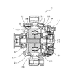
以下、本発明の車両用回転電機を適用した一実施形態の車両用交流発電機について、図面を参照しながら詳細に説明する。図1は、一実施形態の車両用交流発電機の断面図である。図1に示すように、本実施形態の車両用交流発電機1は、界磁として働く回転子2と、電機子として働く固定子3と、これらの回転子2および固定子3を支持するハウジング4と、固定子3に接続されて交流電力を直流に変換する整流器5と、回転子2の界磁電流量を増減して発電量を制御する電圧調整器11とを含んで構成されている。
Hereinafter, an automotive alternator according to an embodiment to which a rotating electrical machine for a vehicle of the present invention is applied will be described in detail with reference to the drawings. FIG. 1 is a cross-sectional view of an AC generator for a vehicle according to an embodiment. As shown in FIG. 1, an
回転子2は、シャフト6と一体になって回転するものであり、ランデル型ポールコア21、冷却ファン22、23、界磁コイル24、スリップリング25、26等によって構成されている。固定子3は、固定子鉄心31と、電機子巻線32と、固定子鉄心31と電機子巻線32とを電気絶縁するシート状の絶縁部材34とで構成されている。この固定子3は、回転子2の外周側に対向配置され、一対のハウジング4によって支持されている。固定子鉄心31は、薄い鋼板シートを重ね合わせて円環状に形成されている。
The rotor 2 rotates integrally with the shaft 6 and includes a Landel
図2は、固定子3の部分断面図である。また、図3は電機子巻線32を構成するセグメント導体の斜視図である。図4は、固定子3の一方のコイルエンド形状を示す部分的な斜視図である。図2に示すように、固定子鉄心31は、外径側から径方向に沿って所定厚みを有する背厚部311と、この背厚部311から内径側に突出したティース部312と、ティース部312の最内周部から周方向に突出して延在するティース先端部313とを備えている。背厚部311とティース部312とティース先端部313とで包囲された空間(予空間)によってスロット314が形成される。同一のスロット314に対応して周方向に隣り合う2つのティース先端部313の対向面の端部には、ほぼ直角の角度をなすティースエッジ部315が形成されている。
FIG. 2 is a partial cross-sectional view of the
スロット314には電機子巻線32が収容されている。この電機子巻線32は、図3に示すセグメント導体33の端部同士を接合することによって形成されている。本実施形態では、電機子巻線32を構成する4本のセグメント導体33が、径方向に一列に配列された状態で各スロット314に収容されている。また、これらのセグメント導体33は、少なくともスロット314に収容された部分の断面が矩形形状であって、スロット314の周方向側面に対向する平面からなる側面を有している。
An armature winding 32 is accommodated in the
セグメント導体33は、図3に示すように、スロット314内に位置する部分33hから一方の先端部33iのみをあらかじめ成形しておいて、この先端部33iと反対側の先端部33jからスロット314内に軸方向に沿って挿入した後に、この反対側の先端部33jを図3に示すP方向に、すなわち円環形状の固定子鉄心31の周方向に折り曲げる。その後、図4に示すように、先端部33j同士を溶接、ろう付け等により接合することで(先端部33iについても同様に接合する)、多相巻線の各相を含む電機子巻線32が形成される。
As shown in FIG. 3, the
また、セグメント導体33と固定子鉄心31の間には、4本のセグメント導体33の周囲を包囲するように絶縁部材34が介在しており、これらの間の電気絶縁が確保されている。なお、各セグメント導体の周囲には絶縁皮膜が形成されており、隣接するセグメント導体33同士の電気絶縁が図られている。
An insulating
本実施形態の固定子鉄心31に形成された各スロット314は、外径側から内径側に向かって次第に周方向幅が狭く設定されている。また、図2に示す例では、スロット内314に収容されて最内径側に配置されたセグメント導体33aは、固定子鉄心31の外径側から内径側に向かって周方向幅が次第に狭くなっており、周方向に沿った両側面がスロット314の周方向側面に当接している。これにより、このセグメント導体33aは、スロット314内の所定位置に、ティース先端部313との間に所定の径方向隙間316を介した状態で係止されている。
Each
このように、スロット314内で最内径側に配置されたセグメント導体33とティース先端部313との間に径方向隙間316が形成された状態でこのセグメント導体33が係止されているため、セグメント導体33の固定子鉄心31から突出している部分の折り曲げ時に周方向に外力が加わってセグメント導体33に内径方向の力が作用しても、最内径側に配置されたセグメント導体33とティースエッジ部315とが直接接触することがない。これにより、ティースエッジ部315にセグメント導体33の一部が押圧されて発生するセグメント導体33表面の絶縁被膜の損傷や絶縁部材34の破損を防止することができ、良好な絶縁状態の確保による使用環境に対する信頼性向上が可能になる。また、固定子鉄心31の各スロット314にセグメント導体33を挿入する場合に、外径側に挿入した後に内径側の所定位置まで移動させるようにすれば、挿入時にセグメント導体33の周囲に十分な隙間を確保することができるため、挿入性を損なうことなく製造の容易化、低コスト化を実現することができる。
As described above, since the
また、少なくとも最内径側に配置されたセグメント導体33の周方向幅が固定子鉄心31の外径側から内径側に向かって狭くなるようにすることで、このセグメント導体33の周方向側面をスロット314の周方向側面と対向させて、セグメント導体33とティース先端部313との間に径方向隙間316を持たせた状態でセグメント導体33を係止することが容易となる。
In addition, the circumferential width of at least the
さらに、少なくとも最内径側に配置されたセグメント導体33は、断面が矩形形状であって、スロット314の周方向側面に対向する平面からなる側面を有している。これにより、セグメント導体33とスロット314の側面とが接触する当接面を広くすることができるため、セグメント導体33表面あるいは絶縁部材34に発生する応力集中を低減することができ、セグメント導体33表面の絶縁被膜や絶縁部材34の破損をさらに低減して信頼性を向上させることが可能となる。
Further, the
なお、本発明は上記実施形態に限定されるものではなく、本発明の要旨の範囲内において種々の変形実施が可能である。上述した実施形態では、スロット314内に収容された4本のセグメント導体33は、内径側から外径側に位置するセグメント導体33の方が周方向幅が広く設定されていたが、図5に示すように、4本のセグメント導体33の断面形状を全て同一の台形形状としてもよい。これにより、セグメント導体33の種類を少なくすることができるとともに、各セグメント導体33を同一素材(例えば連続線)から形成することが可能になるため、部品コストを下げることができる。
In addition, this invention is not limited to the said embodiment, A various deformation | transformation implementation is possible within the range of the summary of this invention. In the embodiment described above, the four
また、図6に示すように、最内径側のセグメント導体33aのみを矩形断面とし、これをストッパーとして機能させ、その他のセグメント導体332を他の形状、例えばほぼ円形断面としてもよい。この場合も、最内周側に配置されたセグメント導体33とティース先端部313との間に径方向隙間316を確保することができる点は同じであり、信頼性の向上とコスト低減が可能となる。
In addition, as shown in FIG. 6, only the
また、図7に示すように、スロット314の内壁面(周方向側面)と対向する平面を側面として有するセグメント導体であれば、断面は台形形状でなくてもよい。例えば、図7に示すように、断面が多角形形状(例えば八角形)のセグメント導体333を用いるようにしてもよい。
Further, as shown in FIG. 7, the cross section may not be trapezoidal as long as it is a segment conductor having a plane opposite to the inner wall surface (circumferential side surface) of the
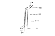
また、図8に示すように、U字ターン部33Cを持つセグメント導体334を用いてもよい。図3に示した直線状のセグメント導体33に対して、セグメント導体334の本数と接合箇所の数を減らすことができるため、製造の容易化による低コスト化を図ることができる。
Further, as shown in FIG. 8, a
また、上述した実施形態では、あらかじめ矩形断面を持つセグメント導体33を用いたが、より汎用性のある円形断面の銅線等を用い、スロット314内に配置される部分のみの断面を矩形形状に加工して用いるようにしてもよい。このとき、より汎用性のある線材を用いることにより、セグメント導体自体のコスト低減が可能となる。
In the embodiment described above, the
1 車両用交流発電機
2 回転子
3 固定子
31 固定子鉄心
311 背厚部
312 ティース部
313 ティース先端部
314 スロット
315 ティースエッジ部
316 径方向隙間
32 電機子巻線
33 セグメント導体
34 絶縁部材
4 ハウジング
DESCRIPTION OF
Claims (3)
前記スロットは、外径側から内径側に向かって次第に周方向幅が狭く設定されており、
前記スロット内に収容されて最内径側に配置された前記セグメント導体は、周方向に沿った両側面が前記スロットの周方向側面に当接することで、前記スロット内の所定位置に、前記ティース先端部と直接接触することなく所定の径方向隙間を介した状態で係止されており、
最内径側に配置された前記セグメント導体は、前記固定子鉄心の外径側から内径側に向かって周方向幅が狭く設定されるとともに、断面が矩形形状であって、前記スロットの周方向側面に対向する平面からなる側面を有することを特徴とする車両用回転電機。 A rotor, and a stator having a stator core disposed on the outer diameter side of the rotor and an armature winding mounted on the stator core, the stator core from the outer diameter side. A thick portion having a predetermined thickness toward the inner diameter direction, a tooth portion protruding from the thick portion toward the inner peripheral side, and a tooth tip portion extending in the circumferential direction from the innermost peripheral portion of the tooth portion are provided. The armature winding is housed in a slot as a space surrounded by the back thick portion, the tooth portion, and the tip end portion of the tooth, and the armature winding joins end portions of a plurality of segment conductors. In the rotating electrical machine for a vehicle formed by the plurality of segment conductors arranged in a row inside the slot,
The slot is set to have a gradually narrower circumferential width from the outer diameter side toward the inner diameter side,
The segment conductor housed in the slot and disposed on the innermost diameter side has both end surfaces in the circumferential direction abutting against the circumferential side surface of the slot, so that the tip of the tooth is positioned at a predetermined position in the slot. It is locked in a state through a predetermined radial gap without directly contacting the part,
The segment conductor arranged on the innermost diameter side has a circumferential width set narrower from the outer diameter side to the inner diameter side of the stator core, and has a rectangular cross section, and the circumferential side surface of the slot A rotating electrical machine for a vehicle having a side surface composed of a flat surface facing the surface.
径方向に一列に配置された状態で前記スロットに収容された複数の前記セグメント導体のそれぞれは、ほぼ同一の断面形状を有していることを特徴とする車両用回転電機。 In claim 1,
Each of the plurality of segment conductors accommodated in the slot in a state of being arranged in a line in the radial direction has substantially the same cross-sectional shape.
前記セグメント導体は、ターン部を有するU字形状を有しており、
2つの前記セグメント導体の反ターン部側端部同士を接合することによって前記電機子巻線を形成することを特徴とする車両用回転電機。 In claim 1 or 2,
The segment conductor has a U shape having a turn part,
The vehicular rotating electrical machine characterized in that the armature winding is formed by joining ends of the two segment conductors opposite to each other on the turn side.
Priority Applications (1)
| Application Number | Priority Date | Filing Date | Title |
|---|---|---|---|
| JP2005158295A JP4609190B2 (en) | 2005-05-31 | 2005-05-31 | Rotating electric machine for vehicles |
Applications Claiming Priority (1)
| Application Number | Priority Date | Filing Date | Title |
|---|---|---|---|
| JP2005158295A JP4609190B2 (en) | 2005-05-31 | 2005-05-31 | Rotating electric machine for vehicles |
Publications (2)
| Publication Number | Publication Date |
|---|---|
| JP2006340409A JP2006340409A (en) | 2006-12-14 |
| JP4609190B2 true JP4609190B2 (en) | 2011-01-12 |
Family
ID=37560476
Family Applications (1)
| Application Number | Title | Priority Date | Filing Date |
|---|---|---|---|
| JP2005158295A Expired - Fee Related JP4609190B2 (en) | 2005-05-31 | 2005-05-31 | Rotating electric machine for vehicles |
Country Status (1)
| Country | Link |
|---|---|
| JP (1) | JP4609190B2 (en) |
Cited By (1)
| Publication number | Priority date | Publication date | Assignee | Title |
|---|---|---|---|---|
| WO2018154943A1 (en) * | 2017-02-21 | 2018-08-30 | パナソニックIpマネジメント株式会社 | Motor |
Families Citing this family (22)
| Publication number | Priority date | Publication date | Assignee | Title |
|---|---|---|---|---|
| EP2112744A1 (en) * | 2008-04-24 | 2009-10-28 | Magneti Marelli Holding S.p.A. | Multiphase synchronous electrical machine for converting kinetic energy into electrical energy and electrical energy into kinetic energy onboard a transport vehicle, and transport vehicle provided with said electrical machine |
| KR101019665B1 (en) | 2008-12-17 | 2011-03-07 | 주식회사 효성 | stator core |
| JP5260399B2 (en) * | 2009-04-24 | 2013-08-14 | 日立オートモティブシステムズ株式会社 | Rotating electric machine for driving vehicle and vehicle using the same |
| IT1396946B1 (en) * | 2009-12-15 | 2012-12-20 | Magneti Marelli Spa | ELECTRIC MACHINE AND TRANSPORTATION VEHICLE PROVIDED WITH THIS ELECTRIC MACHINE |
| WO2012077215A1 (en) * | 2010-12-09 | 2012-06-14 | 株式会社 日立製作所 | Vehicle ac generator |
| JP2012235587A (en) | 2011-04-28 | 2012-11-29 | Aisin Aw Co Ltd | Stator for rotating electric machine |
| JP5778498B2 (en) * | 2011-06-21 | 2015-09-16 | アスモ株式会社 | Stator and motor |
| KR20130013105A (en) * | 2011-07-27 | 2013-02-06 | 현대모비스 주식회사 | Wire loss rate decreasing type driven motor |
| KR20130013104A (en) * | 2011-07-27 | 2013-02-06 | 현대모비스 주식회사 | Wire loss rate decreasing type driven motor |
| JP5854268B2 (en) * | 2012-01-27 | 2016-02-09 | 株式会社デンソー | Rotating electric machine stator |
| CN104160594B (en) | 2012-03-19 | 2016-09-14 | 三菱电机株式会社 | The stator of rotary electric machine for vehicles and manufacture method thereof |
| JP5724984B2 (en) | 2012-10-19 | 2015-05-27 | トヨタ自動車株式会社 | Rotating electric machine stator |
| JP5971125B2 (en) | 2013-01-09 | 2016-08-17 | 株式会社デンソー | Stator and rotating electric machine having the same |
| JP5939446B2 (en) | 2013-03-29 | 2016-06-22 | 株式会社デンソー | Stator, rotating electric machine including the stator, and method for manufacturing the stator |
| JP5531142B2 (en) * | 2013-04-24 | 2014-06-25 | 日立オートモティブシステムズ株式会社 | Rotating electric machine stator and rotating electric machine using the same |
| JP5924703B2 (en) * | 2014-10-22 | 2016-05-25 | 三菱電機株式会社 | Rotating electrical machine stator for vehicles |
| JP6334365B2 (en) * | 2014-10-30 | 2018-05-30 | 三菱電機株式会社 | Manufacturing method of rotating electrical machine |
| US20180331605A1 (en) * | 2015-11-17 | 2018-11-15 | Mitsubishi Electric Corporation | Coil forming device and coil forming method |
| JP7129612B2 (en) * | 2017-01-18 | 2022-09-02 | パナソニックIpマネジメント株式会社 | motor |
| KR102588529B1 (en) * | 2018-05-17 | 2023-10-13 | 현대모비스 주식회사 | Stator assembly for hairpin winding motor |
| JP7347965B2 (en) * | 2019-06-07 | 2023-09-20 | 日立Astemo株式会社 | Stator used in rotating electrical machines |
| US20230387765A1 (en) | 2020-10-07 | 2023-11-30 | Aisin Corporation | Method for manufacturing stator |
Citations (2)
| Publication number | Priority date | Publication date | Assignee | Title |
|---|---|---|---|---|
| JP2000139049A (en) * | 1998-11-02 | 2000-05-16 | Denso Corp | Ac generator for vehicle and manufacture of its stator |
| JP2000358348A (en) * | 1999-04-14 | 2000-12-26 | Denso Corp | Ac generator for vehicle |
Family Cites Families (1)
| Publication number | Priority date | Publication date | Assignee | Title |
|---|---|---|---|---|
| JP3474660B2 (en) * | 1995-01-23 | 2003-12-08 | 株式会社日立製作所 | 3 phase motor |
-
2005
- 2005-05-31 JP JP2005158295A patent/JP4609190B2/en not_active Expired - Fee Related
Patent Citations (2)
| Publication number | Priority date | Publication date | Assignee | Title |
|---|---|---|---|---|
| JP2000139049A (en) * | 1998-11-02 | 2000-05-16 | Denso Corp | Ac generator for vehicle and manufacture of its stator |
| JP2000358348A (en) * | 1999-04-14 | 2000-12-26 | Denso Corp | Ac generator for vehicle |
Cited By (4)
| Publication number | Priority date | Publication date | Assignee | Title |
|---|---|---|---|---|
| WO2018154943A1 (en) * | 2017-02-21 | 2018-08-30 | パナソニックIpマネジメント株式会社 | Motor |
| JPWO2018154943A1 (en) * | 2017-02-21 | 2019-12-19 | パナソニックIpマネジメント株式会社 | motor |
| US11070103B2 (en) | 2017-02-21 | 2021-07-20 | Panasonic Intellectual Property Management Co., Ltd. | Motor |
| JP7050234B2 (en) | 2017-02-21 | 2022-04-08 | パナソニックIpマネジメント株式会社 | motor |
Also Published As
| Publication number | Publication date |
|---|---|
| JP2006340409A (en) | 2006-12-14 |
Similar Documents
| Publication | Publication Date | Title |
|---|---|---|
| JP4609190B2 (en) | Rotating electric machine for vehicles | |
| US8030812B2 (en) | Rotating electric apparatus and method for connecting stator coils thereof | |
| CN108028556B (en) | Rotating electrical machine | |
| US9419484B2 (en) | Stator for rotating electric machine | |
| US20100001609A1 (en) | Rotating electric machine | |
| JP5220549B2 (en) | Stator structure of outer rotor type multipolar generator | |
| JP5005354B2 (en) | Rotating electric machine | |
| WO2012063684A1 (en) | Dynamo-electric machine | |
| JP2000166152A (en) | Stator of ac generator for vehicle and its manufacture | |
| JP5335265B2 (en) | Electric motor | |
| US7728480B2 (en) | Dynamoelectric machine | |
| JP6124493B1 (en) | Rotating electric machine for internal combustion engine and stator thereof | |
| JP5242897B2 (en) | Rotating electric machine for vehicles | |
| JP5105143B2 (en) | motor | |
| CN110635584A (en) | Stator and rotating electrical machine | |
| JP2013207946A (en) | Rotary electric machine | |
| JP4929962B2 (en) | Slotless motor | |
| JP7095649B2 (en) | Terminal connection structure of rotary machine for vehicle drive | |
| JP4547228B2 (en) | 3-phase rotating electric machine | |
| JP3478183B2 (en) | Vehicle alternator and stator manufacturing method used therefor | |
| JP2017225208A (en) | Armature, rotary electric machine, and manufacturing method of armature | |
| WO2019225156A1 (en) | Rotary electric machine and manufacturing method for rotary electric machine | |
| US20210167649A1 (en) | Armature | |
| JP5105144B2 (en) | Motor and armature manufacturing method | |
| JP4548381B2 (en) | Insulator, rotating electric machine, manufacturing method thereof, and electric vehicle |
Legal Events
| Date | Code | Title | Description |
|---|---|---|---|
| A621 | Written request for application examination |
Free format text: JAPANESE INTERMEDIATE CODE: A621 Effective date: 20070709 |
|
| A131 | Notification of reasons for refusal |
Free format text: JAPANESE INTERMEDIATE CODE: A131 Effective date: 20090407 |
|
| A521 | Written amendment |
Free format text: JAPANESE INTERMEDIATE CODE: A523 Effective date: 20090603 |
|
| A131 | Notification of reasons for refusal |
Free format text: JAPANESE INTERMEDIATE CODE: A131 Effective date: 20100105 |
|
| A02 | Decision of refusal |
Free format text: JAPANESE INTERMEDIATE CODE: A02 Effective date: 20100511 |
|
| A521 | Written amendment |
Free format text: JAPANESE INTERMEDIATE CODE: A523 Effective date: 20100729 |
|
| A911 | Transfer of reconsideration by examiner before appeal (zenchi) |
Free format text: JAPANESE INTERMEDIATE CODE: A911 Effective date: 20100812 |
|
| TRDD | Decision of grant or rejection written | ||
| A01 | Written decision to grant a patent or to grant a registration (utility model) |
Free format text: JAPANESE INTERMEDIATE CODE: A01 Effective date: 20100914 |
|
| A01 | Written decision to grant a patent or to grant a registration (utility model) |
Free format text: JAPANESE INTERMEDIATE CODE: A01 |
|
| A61 | First payment of annual fees (during grant procedure) |
Free format text: JAPANESE INTERMEDIATE CODE: A61 Effective date: 20100927 |
|
| FPAY | Renewal fee payment (event date is renewal date of database) |
Free format text: PAYMENT UNTIL: 20131022 Year of fee payment: 3 |
|
| R151 | Written notification of patent or utility model registration |
Ref document number: 4609190 Country of ref document: JP Free format text: JAPANESE INTERMEDIATE CODE: R151 |
|
| FPAY | Renewal fee payment (event date is renewal date of database) |
Free format text: PAYMENT UNTIL: 20131022 Year of fee payment: 3 |
|
| R250 | Receipt of annual fees |
Free format text: JAPANESE INTERMEDIATE CODE: R250 |
|
| R250 | Receipt of annual fees |
Free format text: JAPANESE INTERMEDIATE CODE: R250 |
|
| R250 | Receipt of annual fees |
Free format text: JAPANESE INTERMEDIATE CODE: R250 |
|
| R250 | Receipt of annual fees |
Free format text: JAPANESE INTERMEDIATE CODE: R250 |
|
| R250 | Receipt of annual fees |
Free format text: JAPANESE INTERMEDIATE CODE: R250 |
|
| LAPS | Cancellation because of no payment of annual fees |