JP6593990B2 - Image shake correction apparatus, imaging apparatus, and optical apparatus - Google Patents
Image shake correction apparatus, imaging apparatus, and optical apparatus Download PDFInfo
- Publication number
- JP6593990B2 JP6593990B2 JP2014260451A JP2014260451A JP6593990B2 JP 6593990 B2 JP6593990 B2 JP 6593990B2 JP 2014260451 A JP2014260451 A JP 2014260451A JP 2014260451 A JP2014260451 A JP 2014260451A JP 6593990 B2 JP6593990 B2 JP 6593990B2
- Authority
- JP
- Japan
- Prior art keywords
- image blur
- springs
- holding frame
- holding member
- blur correction
- Prior art date
- Legal status (The legal status is an assumption and is not a legal conclusion. Google has not performed a legal analysis and makes no representation as to the accuracy of the status listed.)
- Active
Links
Images


Classifications
-
- G—PHYSICS
- G02—OPTICS
- G02B—OPTICAL ELEMENTS, SYSTEMS OR APPARATUS
- G02B27/00—Optical systems or apparatus not provided for by any of the groups G02B1/00 - G02B26/00, G02B30/00
- G02B27/64—Imaging systems using optical elements for stabilisation of the lateral and angular position of the image
- G02B27/646—Imaging systems using optical elements for stabilisation of the lateral and angular position of the image compensating for small deviations, e.g. due to vibration or shake
-
- G—PHYSICS
- G03—PHOTOGRAPHY; CINEMATOGRAPHY; ANALOGOUS TECHNIQUES USING WAVES OTHER THAN OPTICAL WAVES; ELECTROGRAPHY; HOLOGRAPHY
- G03B—APPARATUS OR ARRANGEMENTS FOR TAKING PHOTOGRAPHS OR FOR PROJECTING OR VIEWING THEM; APPARATUS OR ARRANGEMENTS EMPLOYING ANALOGOUS TECHNIQUES USING WAVES OTHER THAN OPTICAL WAVES; ACCESSORIES THEREFOR
- G03B5/00—Adjustment of optical system relative to image or object surface other than for focusing
-
- H—ELECTRICITY
- H04—ELECTRIC COMMUNICATION TECHNIQUE
- H04N—PICTORIAL COMMUNICATION, e.g. TELEVISION
- H04N23/00—Cameras or camera modules comprising electronic image sensors; Control thereof
- H04N23/50—Constructional details
- H04N23/55—Optical parts specially adapted for electronic image sensors; Mounting thereof
-
- H—ELECTRICITY
- H04—ELECTRIC COMMUNICATION TECHNIQUE
- H04N—PICTORIAL COMMUNICATION, e.g. TELEVISION
- H04N23/00—Cameras or camera modules comprising electronic image sensors; Control thereof
- H04N23/60—Control of cameras or camera modules
- H04N23/68—Control of cameras or camera modules for stable pick-up of the scene, e.g. compensating for camera body vibrations
- H04N23/682—Vibration or motion blur correction
- H04N23/685—Vibration or motion blur correction performed by mechanical compensation
- H04N23/687—Vibration or motion blur correction performed by mechanical compensation by shifting the lens or sensor position
-
- G—PHYSICS
- G03—PHOTOGRAPHY; CINEMATOGRAPHY; ANALOGOUS TECHNIQUES USING WAVES OTHER THAN OPTICAL WAVES; ELECTROGRAPHY; HOLOGRAPHY
- G03B—APPARATUS OR ARRANGEMENTS FOR TAKING PHOTOGRAPHS OR FOR PROJECTING OR VIEWING THEM; APPARATUS OR ARRANGEMENTS EMPLOYING ANALOGOUS TECHNIQUES USING WAVES OTHER THAN OPTICAL WAVES; ACCESSORIES THEREFOR
- G03B2205/00—Adjustment of optical system relative to image or object surface other than for focusing
- G03B2205/0007—Movement of one or more optical elements for control of motion blur
-
- G—PHYSICS
- G03—PHOTOGRAPHY; CINEMATOGRAPHY; ANALOGOUS TECHNIQUES USING WAVES OTHER THAN OPTICAL WAVES; ELECTROGRAPHY; HOLOGRAPHY
- G03B—APPARATUS OR ARRANGEMENTS FOR TAKING PHOTOGRAPHS OR FOR PROJECTING OR VIEWING THEM; APPARATUS OR ARRANGEMENTS EMPLOYING ANALOGOUS TECHNIQUES USING WAVES OTHER THAN OPTICAL WAVES; ACCESSORIES THEREFOR
- G03B2205/00—Adjustment of optical system relative to image or object surface other than for focusing
- G03B2205/0053—Driving means for the movement of one or more optical element
Landscapes
- Physics & Mathematics (AREA)
- General Physics & Mathematics (AREA)
- Engineering & Computer Science (AREA)
- Multimedia (AREA)
- Signal Processing (AREA)
- Optics & Photonics (AREA)
- Adjustment Of Camera Lenses (AREA)
- Studio Devices (AREA)
Description
本発明は、像振れ補正装置、撮像装置、および光学装置に関し、特に、像振れを補正するために用いて好適なものである。 The present invention relates to an image blur correction device, an imaging device, and an optical device, and is particularly suitable for use in correcting image blur.
従来から、撮像レンズに含まれる像振れ補正用のレンズを、光軸に対し垂直な平面内で移動させることにより、手持ち撮影において生じやすい手振れ等による像振れを抑制する像振れ補正装置(光学防振ユニット)が知られている。
このような像振れ補正装置として、像振れ補正用のレンズを第1の方向あるいは第2の方向(前記第1の方向に垂直な方向)に、光軸回りに回転させることなく移動させるものが知られている。
2. Description of the Related Art Conventionally, an image blur correction apparatus (optical anti-shake device) that suppresses image blur due to camera shake or the like that is likely to occur in handheld shooting by moving an image blur correction lens included in an imaging lens within a plane perpendicular to the optical axis. Vibration unit) is known.
As such an image blur correction apparatus, an image blur correction lens is moved in the first direction or the second direction (direction perpendicular to the first direction) without rotating around the optical axis. Are known.
特許文献1では、以下の技術が開示されている。すなわち、像振れ補正用のレンズを保持するレンズホルダーとベース部材との間に3つのボールを配置する。これら3つのボールの外側にそれぞれ1つずつ配置された3つのバネによって、当該3つのボールを、レンズホルダーとベース部材との間に挟み込む。このようにすることによって、レンズホルダーを光軸と直交する平面内で動かす。 Patent Document 1 discloses the following technique. That is, three balls are arranged between a lens holder that holds a lens for image blur correction and a base member. The three balls are sandwiched between the lens holder and the base member by three springs arranged one by one on the outside of the three balls. By doing so, the lens holder is moved in a plane orthogonal to the optical axis.
しかしながら、特許文献1に開示されているような3つのバネの掛け方だと、レンズホルダーの重心の位置が、3つのバネのバネ力が合成される点から遠い位置になる。このため、力のバランスが崩れて、レンズホルダーの一部が浮き上がり、機構自体が成立しない虞がある。
本発明は、このような問題点に鑑みてなされたものであり、像振れの補正を行うためのレンズを安定して保持できるようにすることを目的とする。
However, when the three springs are applied as disclosed in Patent Document 1, the position of the center of gravity of the lens holder is far from the point where the spring forces of the three springs are combined. For this reason, there is a possibility that the balance of force is lost, a part of the lens holder is lifted, and the mechanism itself is not established.
The present invention has been made in view of such problems, and an object thereof is to stably hold a lens for correcting image blur.
本発明の像振れ補正装置は、地板部材と、像振れ補正用のレンズを保持する保持部材と、前記保持部材を移動させるため前記保持部材に取り付けられる偶数個のアクチュエータの構成部材と、前記保持部材が、前記地板部材に対し、前記像振れ補正用のレンズを除く光学系の光軸に直交する平面内の第1の方向と、前記平面内において前記第1の方向と直交する第2の方向と、に相対的に移動できるように、前記保持部材を支持する支持部材と、一端と他端とがそれぞれ前記保持部材と前記地板部材に取り付けられ、前記地板部材と前記保持部材とで前記支持部材が挟持されるように付勢する複数の付勢部材と、を有し、前記支持部材は、3つのボールであって、前記アクチュエータの構成部材は、4つのマグネット、または、それぞれがコイルを有する4つのコイルユニットであり、前記付勢部材は、4つのバネであって、前記付勢部材は、前記保持部材の周方向で互いに隣接する2つのアクチュエータの構成部材の間の領域に少なくとも1つ配置され、且つ、前記保持部材の周方向で互いに隣接する2つのアクチュエータの構成部材の間の領域であって、前記保持部材の重心を介して互いに対向する2つの領域に配置される前記付勢部材の数が同じであり、前記4つのバネのうちの少なくとも1つのバネは、前記保持部材の重心と前記3つのボールのうちの1つのボールとによって形成される前記像振れ補正用レンズを除く光学系の光軸に直交する平面内における線分から離れた位置に配置されることを特徴とする。 The image blur correction device of the present invention includes a base plate member, a holding member that holds a lens for image blur correction, an even number of actuator constituent members that are attached to the holding member to move the holding member, and the holding A member has a first direction in a plane perpendicular to the optical axis of the optical system excluding the image blur correction lens with respect to the base plate member, and a second direction perpendicular to the first direction in the plane. A support member that supports the holding member, and one end and the other end are attached to the holding member and the base plate member, respectively, and the base plate member and the holding member includes a plurality of urging members for urging to the support member is clamped, and the support member is a three balls, components of the actuator, the four magnets, or respectively co A four coil units with Le, said biasing member is a four springs, the biasing member, the region between the components of the two actuators that are adjacent to each other in the circumferential direction of the holding member At least one and disposed in two regions that are adjacent to each other in the circumferential direction of the holding member and that are opposed to each other via the center of gravity of the holding member Ri the same number der of the biasing member, at least one spring of the four springs, the image blur correction that is formed by the one ball of the center of gravity and the three balls of the holding member characterized Rukoto is located at a distance from the line segment in a plane perpendicular to the optical axis of the optical system excluding the use lenses.
本発明によれば、像振れの補正を行うためのレンズを安定して保持することができる。 According to the present invention, it is possible to stably hold a lens for correcting image blur.
以下に、本発明の一実施形態を、添付の図面に基づいて詳細に説明する。尚、各図では、表記および説明の都合上、本実施形態の説明に必要な部分のみを必要に応じて簡略化して示す。
図1は、撮像装置の概略構成の一例を示す図である。
Hereinafter, an embodiment of the present invention will be described in detail with reference to the accompanying drawings. In addition, in each figure, only the part required for description of this embodiment is simplified and shown as needed on account of description and description.
FIG. 1 is a diagram illustrating an example of a schematic configuration of an imaging apparatus.
図1において、撮像装置100は、カメラ本体110とレンズ鏡筒120とを有する。レンズ筐体120は、カメラ本体110に装着されるものでも、カメラ本体110と一体となっているものでもよい。
レンズ鏡筒120は、1群レンズL1、2群レンズL2、3群レンズL3、および固定絞り29を含む撮像レンズ光学系を有する。また、本実施形態では、レンズ鏡筒120に撮像素子122が取り付けられる。
In FIG. 1, the
The
さらに、レンズ鏡筒120は、駆動装置123を有する。駆動装置123は、レンズ鏡筒120の各部を駆動させるためのものである。駆動装置123は、例えば、撮像装置100の振れ(振動)を検出するセンサからの情報と、防振レンズとしての機能を有する2群レンズL2の位置を検出するセンサからの情報とに基づいて、2群レンズL2の移動量および移動方向を計算する。そして、後述する像振れ補正装置は、駆動装置123で計算された結果に従って、2群レンズL2を駆動させる。
Further, the
カメラ本体110は、A/D変換器111、画像処理部112、表示部113、操作部114、記憶部115、およびシステム制御部116を有する。
被写体の像は、撮像レンズ光学系を介して撮像素子122に結像される。撮像素子122は、結像された被写体の像(光信号)をアナログの電気信号に変換する。A/D変換器111は、撮像素子122から出力されたアナログの電気信号をデジタルの電気信号(画像信号)に変換する。画像処理部112は、A/D変換器111から出力されたデジタルの電気信号(画像信号)に対して種々の画像処理を行う。
The
The image of the subject is formed on the
表示部113は、各種の情報を表示する。表示部113は、例えば、電子ビューファインダや液晶パネルを用いることにより実現される。操作部114は、撮像装置100に対する指示をユーザが行うためのユーザインタフェースとしての機能を有する。尚、表示部113がタッチパネルを有する場合には、当該タッチパネルも操作部114の一つになる。
The
記憶部115は、画像処理部112で画像処理が行われた画像データ等、各種のデータを記憶する。また、記憶部115は、プログラムも記憶する。記憶部115は、例えば、ROM、RAM、およびHDDを用いることにより実現される。
システム制御部116は、撮像装置100全体を統括制御する。システム制御部116は、例えば、CPUを用いることにより実現される。
The
The
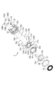
図2は、レンズ鏡筒120の構成の一例を示す分解斜視図である。
先ず、図2を参照して、本実施形態のレンズ鏡筒120の構成について説明する。
1群鏡筒1は、1群レンズL1を保持するためのものである。1群鏡筒1の内周面の下方に配置された3つのカムピン1aは、カム筒5の外周面に形成されたカム溝5aに係合される。また、1群鏡筒1の内周面3箇所には、不図示の直進溝が形成されている。これらの直進溝は、直進筒4の外周面の上端に形成された直進キー4aに係合される。
FIG. 2 is an exploded perspective view showing an example of the configuration of the
First, the configuration of the
The first group barrel 1 is for holding the first group lens L1. Three cam pins 1 a arranged below the inner peripheral surface of the first group barrel 1 are engaged with
2群鏡筒2は、2群レンズL2を保持するためのものである。2群鏡筒2の外周面の下方に配置された3つのカムピン2aは、カム筒5の内周面に形成されたカム溝5bに係合される。また、2群鏡筒2には、カムピン2aと同じ箇所に直進キー2bが形成されている。直進キー2bは、直進筒4に形成された直進溝4bに係合される。
カム筒5の内周面の上方に形成されたカム溝5cには、直進筒4の外周面の上方に配置された3つのカムピン4cが係合される。
The second group barrel 2 is for holding the second group lens L2. Three cam pins 2 a arranged below the outer peripheral surface of the second group barrel 2 are engaged with
Three
1群鏡筒1および2群鏡筒2は、直進筒4に回転不能に支持されている。駆動装置123によりカム筒5が回転されると、カム筒5は、カム筒5のカム溝5cと直進筒4のカムピン4cとの作用により、回転しながら光軸方向に移動する。
1群鏡筒1は、1群鏡筒1のカムピン1aとカム筒5のカム溝5aとの作用、および、1群鏡筒1の直進溝1bと直進筒4の直進キー4aとの作用により、回転することなく光軸方向に移動する。
The first group barrel 1 and the second group barrel 2 are supported by the rectilinear barrel 4 so as not to rotate. When the
The first group barrel 1 is operated by the action of the
2群鏡筒2は、2群鏡筒2のカムピン2aとカム筒5のカム溝5bとの作用、および、2群鏡筒2の直進キー2bと直進筒4の直進溝4bとの作用により、回転することなく光軸方向に移動する。
The second group lens barrel 2 is caused by the action of the
3群保持枠3は、3群レンズL3を保持するためのものである。3群保持枠3に形成された位置決め部3aと振れ止め部3bは、固定地板6に配置されたガイドバー6a、6bに係合され、光軸方向に移動可能に支持されている。駆動装置123により3群保持枠3が駆動されると、3群保持枠3は、位置決め部3aおよび振れ止め部3bと、ガイドバー6a、6bとの作用により、回転することなく光軸方向に移動する。
The third
撮像素子122(図1を参照)と光学フィルタL0は固定地板6に保持される。また、直進筒4は不図示のビスにより固定地板6に固定される。 The image sensor 122 (see FIG. 1) and the optical filter L0 are held on the fixed ground plane 6. Further, the rectilinear cylinder 4 is fixed to the fixed base plate 6 with a screw (not shown).
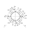
図3は、2群鏡筒2の構成の一例を示す分解斜視図である。図4は、図3に示す2群鏡筒2の正面図である。図5は、図3に示す2群鏡筒2の背面図である。また、図6Aは、2群鏡筒2のボールとバネとの位置関係の一例を説明する図であり、図6Bは、図6AのD1部の部分拡大図である。
図3〜図6を参照しながら、2群鏡筒2の構成の一例を説明する。2群鏡筒2は、像振れ補正装置として機能する。
図3において、2群保持枠21は、2群レンズL2を保持する。尚、以下の説明では、2群レンズを必要に応じて補正レンズと称する。
FIG. 3 is an exploded perspective view showing an example of the configuration of the second group barrel 2. FIG. 4 is a front view of the second group barrel 2 shown in FIG. FIG. 5 is a rear view of the second group barrel 2 shown in FIG. 6A is a diagram for explaining an example of the positional relationship between the ball and the spring of the second group barrel 2, and FIG. 6B is a partially enlarged view of a portion D1 in FIG. 6A.
An example of the configuration of the second group barrel 2 will be described with reference to FIGS. The second group barrel 2 functions as an image blur correction device.
In FIG. 3, the second
2群保持枠21には、マグネット21A1、21A2、21B1、21B2が一体的に保持される。尚、符号における添字AおよびBは、図4におけるA軸方向およびB軸方向と対応している。ここで、A軸方向は、2群保持枠21が駆動される第1の方向であり、2群レンズL2を除く光学系の光軸と直交する平面内の方向である。B軸方向は、2群保持枠21が駆動される第2の方向であり、2群レンズL2を除く光学系の光軸と直交する平面内においてA軸方向に直交する方向である。
Magnets 21A1, 21A2, 21B1, and 21B2 are integrally held by the second
また、図4に示すように、2群保持枠21の周方向において相互に間隔を有して隣接する2つのマグネットの間には、フック係止部21a、21b、21c、21dがそれぞれ1つずつ設けられている。フック係止部21a、21b、21c、21dには、引張り力を作用させるバネ25a、25b、25c、25dが掛けられる。これら複数のバネ25a、25b、25c、25dは、組立性を鑑みて2群保持枠21の外周に可及的に沿うように配置される。本実施形態では、バネ25a、25b、25c、25dは、コイル状のバネであり、一端と他端とに、バネ25a、25b、25c、25dを他の部材に掛けるようにするためのフック部が形成されたものである。
Also, as shown in FIG. 4, one
固定絞り29は、有害光をカットするためのものであり、2群保持枠21に固定される。コイルユニット23A1、23A2、23B1、23B2は、コイルとボビンとを有する。コイルユニット23A1、23A2、23B1、23B2は、2群地板22の窪みに接着されることにより固定される。前記ボビンに埋設された金属ピンであって、前記コイルと電気的に接続された金属ピンに対して、後述する2群FPC27(フレキシブルプリント基板)によって給電が行われることにより、前記コイルへの給電が行われる。
The fixed
2群保持枠21に掛けられた4つのバネ25a、25b、25c、25dの他端は、2群地板22に形成されたフック係止部に掛けられる。このフック係止部は、4つのバネ25a、25b、25c、25dに対して1つずつ設けられる。図3では、表記の都合上、4つのフック係止部のうち、バネ25dの他端が掛けられるフック係止部22dのみを示す。
The other ends of the four
2群地板22と2群保持枠21との間には3個の非磁性のボール24a、24b、24cが挟まれている。2群保持枠21は、2群地板22に向かってボール24a、24b、24cを介して押圧された状態になっている。ただし、2群保持枠21は、ボール24a、24b、24cを介して押圧されているので、光軸に垂直な平面内で移動することが可能である。2群保持枠21をこの平面内で移動させることによって、2群地板22に対し補正レンズL2をこの平面内で相対的に移動させることができる。その結果、撮像素子122上の像振れが抑制され、像振れの補正が行われる。
Three
以上のように、2群保持枠21は、像振れ補正用レンズの一例である2群レンズL2を保持する保持部材であり、2群地板22は、2群鏡筒2の地板部材である。
また、ボール24a、24b、24cは、2群保持枠21が2群地板22に対し、補正レンズL2を除く光学系の光軸と直交する平面内で相対的に移動できるように、2群保持枠21を支持する支持部材である。
また、バネ25a、25b、25c、25dは、一端が2群保持枠21に取り付けられると共に他端が2群地板22に取り付けられ、2群保持枠21と2群地板22とでボール24a、24b、24cが挟持されるように付勢する付勢部材である。
As described above, the second
The
The
2群FPC27には、コイルユニット23A1、23A2、23B1、23B2と半田により電気的に接続するためのランドが設けられている。また、2群FPC27の裏面側には、磁界を検出する(不図示の)2つのホール素子が実装されている。
The
2群保持枠21に保持されるマグネット21A1、21A2、21B1、21B2は、図4に示す方向に着磁されている(図4のN、Sを参照)。2群保持枠21のA軸方向およびB軸方向への移動を、各ホール素子が磁界の変化として検出する。駆動装置123は、その変化量に基づいて、2群保持枠21(2群レンズL2)の移動量を算出する。マグネット21A1、21B1とホール素子の位置精度は重要である。したがって、ホール素子は、センサ支持枠26に対して圧入されて精度良く位置決めされる。
The magnets 21A1, 21A2, 21B1, 21B2 held by the second
2群FPC27は、位置決め穴27a、27bとセンサ支持枠26の位置決め突起26a、26bとの係合によって固定される。また、2群カバー28を不図示のバヨネット構造で2群地板22に固定することにより、センサ支持枠26が2群地板22に対して固定される。
The
次に、図4を参照しながら、補正レンズL2を保持する2群保持枠21の2群地板22に対する安定性について説明する。
2群保持枠21は、モールド部材で成形されており、前述したように補正レンズL2とマグネット21A1、21A2、21B1、21B2とを備える。したがって、2群保持枠21の自重は、主に、補正レンズL2の重さとマグネット21A1、21A2、21B1、21B2の重さによって支配される。像振れ補正のための駆動開始時には、マグネット21A1、21A2、21B1、21B2およびコイル23A1、23A2、23B1、23B2の駆動力により、重量に抗して、2群保持枠21が持ち上がる。このとき、補正レンズL2の中心が、補正レンズL2以外の他の撮影レンズ光学系の光軸に一致するように、2群保持枠21が持ち上がる。
Next, the stability of the second
The second
図4は、補正レンズL2の中心が、補正レンズL2以外の他の撮影レンズ光学系の光軸に一致するように2群保持枠21を持ち上げた状態を表す。2群保持枠21は上下左右対称の形状になっており、且つ、マグネット21A1、21A2、21B1、21B2も上下左右対称に配置されている。したがって、前記状態のときには、マグネット21A1、21A2、21B1、21B2が取り付けられ、補正レンズL2を保持した2群保持枠21の重心は、光軸と同じ位置となる。
FIG. 4 shows a state in which the second
また、2群保持枠21を受ける3つのボール24a、24b、24cで形成される三角形が2群保持枠21の重心を内部に含まれるように、当該3つのボール24a、24b、24cを配置する。これにより、2群保持枠21を安定して保持することができる。例えば、3つのボール24a、24b、24cから形成される三角形内に、2群保持枠21の重心が含まれないように、3つのボール24a、24b、24cを配置すると、2群保持枠21の重心側に2群保持枠21が倒れる。これにより、2群保持枠21が、光軸と直交する平面内で移動することが不可能となる。尚、図4において、3つのボール24a、24b、24cは2群保持枠21の裏面にあるため、当該3つのボール24a、24b、24cを破線で示す。
Further, the three
2群保持枠21には、前述したように、2群保持枠21と2群地板22との間において、4つのバネ25a、25b、25c、25dが掛けられる(図3を参照)。このとき、4つのバネ25a、25b、25c、25dの軸方向が光軸の方向と平行になる。このように、2群保持枠21と2群地板22とが互いに押し合うようにバネ25a、25b、25c、25dを掛けることにより、3つのボール24a、24b、24cが、2群保持枠21と2群地板22によって挟持される。
As described above, the four
本実施形態では、2群保持枠21が上下左右対称の形状になっており、且つ、マグネット21A1、21A2、21B1、21B2も上下左右対称に配置されている。したがって、4つのバネ25a、25b、25c、25dのバネ力が合成される点が、3つのボール24a、24b、24cから形成される三角形の内側の位置であって、光軸と同じ位置の2群保持枠21の重心にあることが最も安定性を保てる条件となる。つまり、2群保持枠21に掛ける4つのバネ25a、25b、25c、25dは、前述の三角形に対してどのようにでも掛ける自由度はある。ただし、像振れ装置としての安定性を確実にするためには、2群保持枠21の重心から均等となる位置に4つのバネ25a、25b、25c、25dを配置することが望ましい。
In the present embodiment, the second
本実施形態では、上下左右対称に配置されているマグネット21A1、21A2、21B1、21B2に対してそれぞれのマグネットの間に4つのバネ25a、25b、25c、25dを1つずつ配置している。このことにより、補正レンズL2を保持する2群保持枠21の安定性の向上を図っている。
In the present embodiment, four
また、左右の2つのバネ25c、25dは、X軸線上に配置されるようにすると共に、上下の2つのバネ25a、25bは、Y軸線上から僅かに離れた位置に配置されるようにする。図5に示すように、ボール24cは、前述した2群保持枠21およびマグネット21A1、21A2、21B1、21B2の対称性を鑑みてY軸線上に配置される。
図6Aに示すように、バネ25b´をY軸線上に配置した場合、図6Bに示すように、バネ25b´と、バネ25b´の駆動範囲S´と、フック係止部21b´とが、本実施形態の2群保持枠21の最外径部よりも外側に食み出す。
The left and
As shown in FIG. 6A, when the
これに対し、本実施形態では、バネ25bをY軸線上から僅かに離れた位置に配置する。すなわち、バネ25bは、2群保持枠21の重心とボール24c(の中心)とによって形成される線分から離れた位置に配置される。このようにすることによって、バネ25bと、バネ25bの駆動範囲Sと、フック係止部21bとが、2群保持枠21の最外径部の外側に食み出ないようにする。このことにより、2群保持枠21の小型化を図ることができる。
On the other hand, in this embodiment, the
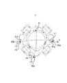
図7Aは、2群保持枠21においてX軸方向に作用する力の一例を示す図である。図7Bは、図7AのD2部の部分拡大図である。図8は、一般的な撮像装置(カメラ)に具備される像振れ補正装置の保持枠および地板の構成を示す正面図である。また、図9は、図8に示す保持枠において、X軸方向に作用する力を示す図である。
FIG. 7A is a diagram illustrating an example of a force acting in the X-axis direction on the second
図10は、2群保持枠21のフック係止部21dにおいて、A軸方向に作用する力の一例を示す図である。図11は、2群保持枠21のフック係止部21dにおいて、B軸方向に作用する力の一例を示す図である。
図12は、2群保持枠21において、回転方向に作用する力の一例を示す図である。図13は、2群保持枠21において、Y軸方向に作用する力の一例を示す図である。図14は、2群保持枠21において、A軸方向に作用する力の一例を示す図である。図15は、2群保持枠21において、B軸方向に作用する力の一例を示す図である。
FIG. 10 is a diagram illustrating an example of a force acting in the A-axis direction at the
FIG. 12 is a diagram illustrating an example of a force acting in the rotation direction in the second
次に、図7A〜図15を参照しながら、ローリングを防止する4つのバネ25a、25b、25c、25dの具体的な掛け方の一例を、一般的なバネの掛け方と比較しながら説明する。
ローリングとは、像振れ補正のための駆動力が働いた時に2群保持枠21の重心に対して回転しようとする力である。本実施形態では、マグネット21A1、21A2、21B1、21B2のそれぞれの重心から伸びる像振れ補正の駆動軸が2群保持枠21の重心を通る。このため、像振れ補正のための駆動力によって2群保持枠21が回転することはない。しかし、4本のバネ25a、25b、25c、25dの掛け方によっては駆動力に対する反力が2群保持枠21に働くため、2群保持枠21が回転することがある。
Next, referring to FIGS. 7A to 15, an example of a specific method for hanging the four
Rolling is a force that attempts to rotate relative to the center of gravity of the second
本実施形態では、4つのバネ25a、25b、25c、25dは、2群保持枠21の重心を挟んで向かい合う位置に配置される2つのバネを1組とする2組の2つのバネ(バネ25a、25bおよびバネ25c、25d)からなる。これら2つのバネ(バネ25a、25bおよびバネ25c、25d)は、2組とも、それぞれ2群保持枠21の重心に対して点対称となる位置に配置される。また、バネ25aの一端部を構成する不図示のフック部が作る平面と、バネ25bの一端部を構成する不図示のフック部が作る平面とが、2群保持枠21の重心に対して点対称になるように、バネ25a、25bを配置する。同様に、バネ25cの一端部を構成する不図示のフック部が作る平面と、バネ25dの一端部を構成するフック部25hが作る平面とが、2群保持枠21の重心に対して点対称になるように、バネ25c、25dを配置する。
In the present embodiment, the four
詳しくは、バネ25a、25b、25c、25dのうち一方の組の2つのバネ25a、25bのフック部が作る平面が、それぞれA軸方向に平行になるようにする。また、バネ25a、25b、25c、25dのうち他方の組の2つのバネ25c、25fのフック部が作る平面が、それぞれB軸方向に平行になるようにする。
以上のようにすることにより、2群保持枠21におけるローリングの影響を低減することができる(詳細は後述する)。
Specifically, the planes formed by the hook portions of the two
By doing so, the influence of rolling on the second
図8は、3つのバネ85a、85b、85cが保持枠81に掛けられている様子を示す。具体的に、地板82と保持枠81との間に3つのボール84a、84b、84cを配置して、地板82と保持枠81のフック係止部81a、81b、81cに3つのバネ85a、85b、85cのフック部を掛ける。これにより、保持枠81が光軸と直交する平面を動くことができる。
FIG. 8 shows a state in which three
左右の2つのバネ85a、85bは、保持枠81の重心に対して左右対称になる位置に配置される。バネ85cは、左右の2つのバネ85a、85bの対称軸線に近い中央位置に配置される。このように3つのバネ85a、85b、85cが掛けられた保持枠81がX軸に沿って少し動いた状態を示したものが図9である。図9では、X軸に沿った駆動によって前述のローリング力が、保持枠81の重心に対して働いている様子を示す。
The two left and
図9において、像振れ補正のための駆動力に対する反力r1、r2、r3が、3つのバネ85a、85b、85cによって保持枠81に働く。
左右の2つのバネ85a、85bに対しては、保持枠81の重心に対して保持枠81を反時計回りに回転させようとする力r4、r5が生じる。この力r4、r5は、反力r1、r2の分力である。
また、中央のバネ85cに対しては、保持枠81の重心に対して保持枠81を時計回りに回転させようとする力r3が生じる。この力r3は、反力r3の分力である。
In FIG. 9, reaction forces r1, r2, and r3 against a driving force for image blur correction act on the holding
For the left and
In addition, a force r3 that causes the holding
しかし、中央のバネ85cの配置によって、r4+r5>r6もしくはr4+r5<r6となる。このため、保持枠81には、その差分の力で、保持枠81の重心に対して反時計周りもしくは時計周りに回転しようとするローリングが発生する。
すなわち、図8および図9に示す構成においては、中央のバネ85cの配置によって、ローリングを発生させる方向にバネ力が働く。このため、防振性能に支障を来たすことがある。
However, r4 + r5> r6 or r4 + r5 <r6 depending on the arrangement of the
That is, in the configuration shown in FIGS. 8 and 9, the spring force acts in the direction of generating rolling due to the arrangement of the
図7Aは、図9と同様に、本実施形態の2群保持枠21が、X軸に沿って、図7Aの右方向に少し動いた状態を示す。
像振れ補正のための駆動力が働いた場合、2群保持枠21は、その駆動力に対する反力R11、R12、R13、R14を、4つのバネ25a、25b、25c、25dから受ける。したがって、2群保持枠21のフック係止部21a、21b、21c、21dは、その反力R11、R12、R13、R14を受ける。その反力R11、R12、R13、R14の大きさは、バネ25a、25b、25c、25dのフック部がフック係止部21a、21b、21c、21dに対してどのように掛かっているかによって変わる。
FIG. 7A shows a state in which the second
When a driving force for image blur correction is applied, the second
尚、図7Bでは、バネ25dのフック部25hのみを示すが、その他のバネ25a、25b、25cのフック部も、バネ25dのフック部25hと同じ構成である。本実施形態では、フック部25hの形状は、リング状である(図11を参照)。ただし、フック部の形状は、リング状に限定されず、例えば、円弧状、V字状、またはU字状を採用することができる。
7B shows only the
図7Bは、図7Aに示す2群保持枠21の右側のフック係止部21dの周り(D2部)を拡大して示す図である。
フック係止部21aは、バネ25aのフック部が作る平面が像振れ補正のための駆動方向であるA軸方向と平行になるような形状になっている。フック係止部21bも、バネ25bのフック部が作る平面が像振れ補正のための駆動方向であるA軸方向と平行になるような形状になっている。
FIG. 7B is an enlarged view showing the periphery (D2 portion) around the
The
一方、フック係止部21cは、バネ25cのフック部が作る平面が像振れ補正のための駆動方向であるB軸方向と平行になるような形状となっている。フック係止部21dもバネ25dのフック部25hが作る平面が像振れ補正のための駆動方向であるB軸方向と平行になるような形状となっている。
On the other hand, the
尚、バネ25dのフック部25hが作る平面は、フック部25hのリング状の領域により形成される平面である。図11に示すように、フック部25hのリング状の領域により形成される平面の形状は、円である。また、図7Bに示すように、フック部25hのリング状の領域により形成される平面はB軸方向に平行な面である。以上のことは、その他のバネ25a、25b、25cのフック部についても同じである。ただし、バネ25a、25bのフック部のリング状の領域により形成される平面はA軸方向に平行な面である。
Note that the plane formed by the
したがって、バネ25a、25b、25c、25dのフック部の、2群保持枠21のフック係止部21a、21b、21c、21dに対する摩擦力は、A軸方向とB軸方向とで異なる。バネ25dのフック部25hは、バネ力により2群保持枠21のフック係止部21dの溝の最下点に位置する、このため、2群保持枠21がA軸方向に変位したとしても、当該最下点でフック部25hが転がってその変位を吸収しようとする。
Therefore, the frictional force of the hook portions of the
また、2群保持枠21がB軸方向に変位したときは、フック部25hは、その形状に基づく自由度の範囲内で、フック係止部21dとの接触点が常に擦れながら変化する。フック部25hの線の半径(転がり径)は、フック部25hのリング(円)の半径に対して小さい。
Further, when the second
このため、摩擦力としては後者に対し前者の方が小さくなる。A軸方向では、フック係止部21dに対してバネ25dのA軸方向の分力NAと摩擦力FA(垂直抗力N×摩擦係数ΜA)との合力R14Aが働く(図7Bおよび図10を参照)。これに対し、B軸方向では、フック係止部21dに対してバネ25dのB軸方向の分力NBと摩擦力FB(垂直抗力N×摩擦係数ΜB)との合力R14Bが働く(図7Bおよび図11を参照)。
For this reason, the former is smaller as the frictional force than the latter. In the A-axis direction, a resultant force R14A of a component force NA in the A-axis direction of the
したがって、図7Aにおいて、反力は、A軸方向の力とB軸方向の力とを合わせた合力R14となる。よって、2群保持枠21の重心に対して2群保持枠21を回転させようとする力は、図12に示すように分力R18として表れる。
尚、ここでは、バネ25dのフック部25hをフック係止部21dに掛けた場合を例に挙げて説明した。しかしながら、バネ25a、25b、25cをフック係止部に掛けた場合も、バネ25dのフック部25hをフック係止部21dに掛けた場合と同様に、合力R11、R12、R13と、回転方向の分力R15、R16、R17とが表れる(図12を参照)。
Therefore, in FIG. 7A, the reaction force is a resultant force R14 that is the sum of the A-axis direction force and the B-axis direction force. Therefore, the force to rotate the second
Here, the case where the
また、本実施形態では、バネ25a、25bを2群保持枠21の重心に対して点対称に配置する。さらに、バネ25aの一端部を構成するフック部が作る平面と、バネ25bの一端部を構成するフック部が作る平面とを2群保持枠21の重心に対して点対称になるように配置する。このため、フック係止部21a、21bが受ける回転方向の分力R15、R16は等しくなる。同様に、バネ25c、25dを2群保持枠21の重心に対して点対称に配置する。さらに、バネ25cの一端部を構成するフック部が作る平面と、バネ25dの一端部を構成するフック部25hが作る平面とを2群保持枠21の重心に対して点対称になるように配置する。このため、フック係止部21c、21dが受ける回転方向の分力R17、R18は等しくなる。
In the present embodiment, the
この場合、フック係止部21a、21bが受ける回転方向の分力R15、R16の方向は、互いに相殺する方向である。さらに、フック係止部21c、21dが受ける回転方向の分力R17、R18の方向も、互いに相殺する方向である。
したがって、前述したバネ25a、25b、25c、25dの掛け方によってローリングを相殺する方向に力が働く。
In this case, the directions of the component forces R15 and R16 in the rotational direction received by the
Therefore, a force acts in a direction that cancels rolling by the manner in which the
実際には、バネ25a、25b、25c、25dの掛け方で、分力R15、R16、R17、R18の方向や強弱が変わる。しかし、フック係止部21a、21bが受ける回転方向の分力R15、R16、および、フック係止部21c、21dが受ける回転方向の分力R17、R18は、それぞれ互いに相殺されることに代わりはない。したがって、ここでは、バネ25a、25b、25c、25dのその他の掛け方についての詳細な説明は省略する。
Actually, the direction and strength of the component forces R15, R16, R17, and R18 vary depending on how the
また、ここでは、像振れ補正のための駆動として2群保持枠21をX軸方向の一側(図12の右側)に動かした場合を例に挙げて説明した。2群保持枠21は、上下左右対称の形状であるため、X軸方向の他側(図12の左側)に2群保持枠21を動かした場合も、X軸方向の一側(図12の右側)に2群保持枠21を動かした場合と同様、2群保持枠21にローリングは発生しない。
Here, the case where the second
図13は、像振れ補正のための駆動により2群保持枠21がY軸に沿って図の上方に少し動いた状態を示す。
像振れ補正のための駆動力が働いた場合、2群保持枠21は、その駆動力に対する反力R21、R22、R23、R24を、4つのバネ25a、25b、25c、25dから受ける。この場合、2群保持枠21がバネ25a、25bのフック係止部21a、21bが受ける回転方向の分力R25、R26の方向は、互いに相殺する方向である。また、バネ25c、25dのフック係止部21c、21dが受ける回転方向の分力R27、R28の方向も、互いに相殺する方向である。したがって、2群保持枠21にローリングは発生しない。
FIG. 13 shows a state in which the second
When a driving force for image blur correction is applied, the second
ここでは、像振れ補正のための駆動として2群保持枠21をY軸方向の一側(図13の上側)に動かした場合を例に挙げて説明した。2群保持枠21は、上下左右対称の形状である。このため、Y軸方向の他側(図13の下側)に2群保持枠21を動かした場合も、Y軸方向の一側(図13の上側)に2群保持枠21を動かした場合と同様、2群保持枠21にローリングは発生しない。
Here, the case where the second
図14は、像振れ補正のための駆動により、2群保持枠21がA軸に沿って図の斜め右上の方向に少し動いた状態を示す。
像振れ補正のための駆動力が働いた場合、2群保持枠21は、その駆動力に対する反力R31、R32、R33、R34を4つのバネ25a、25b、25c、25dから受ける。
FIG. 14 shows a state in which the second
When a driving force for image blur correction is applied, the second
バネ25a、25bのフック部25が作る平面は、2群保持枠21の駆動方向と平行である。したがって、フック係止部21a、21bが受ける反力R31、R32に、バネ25a、25bのフック部が作る平面に直交する方向の分力、摩擦力は作用しない。
同様に、バネ25c、25dのフック部が作る平面は、2群保持枠21の駆動方向と直交する。したがって、フック係止部21c、21dが受ける反力R33、R34に、バネ25c、25dのフック部が作る平面に平行な方向の分力、摩擦力は作用しない。
The plane formed by the hook portions 25 of the
Similarly, the plane formed by the hook portions of the
この場合、フック係止部21a、21bが受ける回転方向の分力R35、R36の方向は、互いに相殺する方向である。フック係止部21c、21dが受ける回転方向の分力R37、R38の方向も、互いに相殺する方向である。したがって、この場合も、2群保持枠21にローリングは発生しない。
In this case, the directions of the component forces R35 and R36 in the rotational direction received by the
ここでは、像振れ補正の駆動として2群保持枠21をA軸方向の一側(図14の斜め右上の方向)に動かした場合を例に挙げて説明した。2群保持枠21は、上下左右対称の形状である。このため、A軸方向の他側(図14の斜め左下の方向)に2群保持枠21を動かした場合も、A軸方向の一側(図14の斜め右上の方向)に2群保持枠21を動かした場合と同様、2群保持枠21にローリングは発生しない。
Here, the case where the second
図15は、像振れ補正のための駆動により、2群保持枠21がB軸に沿って図の斜め右下の方向に少し動いた状態を示す。
像振れ補正のための駆動力が働いた場合、2群保持枠21は、その駆動力に対する反力R41、R42、R43、R44を4つのバネ25a、25b、25c、25dから受ける。
FIG. 15 shows a state in which the second
When a driving force for image blur correction is applied, the second
バネ25a、25bのフック部が作る平面は、2群保持枠21の駆動方向と直交する。したがって、フック係止部21a、21bが受ける反力R41、R42に、バネ25a、25bのフック部が作る平面に平行な方向の分力、摩擦力は作用しない。
同様に、バネ25c、25dのフック部が作る平面は、2群保持枠21の駆動方向と平行である。したがって、フック係止部21c、21dが受ける反力R43、R44に、バネ25c、25dのフック部25が作る平面に直交する方向の分力、摩擦力は作用しない。
The plane formed by the hook portions of the
Similarly, the plane formed by the hook portions of the
この場合、フック係止部21a、21bが受ける回転方向の分力R45、R46の方向は、互いに相殺する方向である。フック係止部21c、21dが受ける回転方向の分力R47、R48の方向も互いに相殺する方向である。したがって、この場合も、2群保持枠21にローリングは発生しない。
In this case, the directions of the component forces R45 and R46 in the rotational direction received by the
ここでは、像振れ補正のための駆動として2群保持枠21をB軸方向の一側(図15の斜め右下の方向)に動かした場合を例に挙げて説明した。2群保持枠21は、上下左右対称の形状である。このため、B軸方向の他側(図15の斜め左上の方向)に2群保持枠21を動かした場合も、B軸方向の一側(図15の斜め右下の方向)に2群保持枠21を動かした場合と同様、2群保持枠21にローリングは発生しない。
Here, the case where the second
以上のように、2群保持枠21をXY平面において、X軸方向、Y軸方向、A軸方向、およびB軸方向に駆動させた場合、いずれの場合もローリングを相殺する方向にバネ力が作用する。
また、これら以外の駆動方向に2群保持枠21を動かした場合も、何れかの駆動の組み合わせとなり、ローリングを相殺する方向にバネ力が作用することは変わらない。
As described above, when the second
Further, even when the second
以上のように本実施形態における像振れ補正装置では、上下左右対称に配置されているマグネット21A1、21A2、21B1、21B2に対してそれぞれのマグネットの間に4つのバネ25a、25b、25c、25dを1つずつ配置する。このことにより、補正レンズL2を保持する2群保持枠21の安定性の向上を図ることができる。
As described above, in the image shake correction apparatus according to the present embodiment, the four
さらに、2群保持枠21の重心を挟んで向かい合う2つのバネ(バネ25a、25bおよびバネ25cと25d)をそれぞれ2群保持枠21の重心に対して点対称に配置する。また、バネ25aの一端部を構成するフック部が作る平面と、バネ25bの一端部を構成するフック部が作る平面とが、2群保持枠21の重心に対して点対称になるように、バネ25a、25bを配置する。同様に、バネ25cの一端部を構成するフック部が作る平面と、バネ25dの一端部を構成するフック部25hが作る平面とが、2群保持枠21の重心に対して点対称になるように、バネ25c、25dを配置する。以上のようにすることにより、2群保持枠21におけるローリングに対する影響を低減することができる。
Further, two springs (springs 25 a and 25 b and springs 25 c and 25 d) facing each other with the center of gravity of the second
以上、本発明の一実施形態について説明したが、本発明の技術的範囲は、本実施形態で説明したものに限定されず、その要旨の範囲内で種々の変形および変更が可能である。 As mentioned above, although one Embodiment of this invention was described, the technical scope of this invention is not limited to what was demonstrated by this Embodiment, A various deformation | transformation and change are possible within the range of the summary.
例えば、本実施形態では、マグネット21A1、21A2、21B1、21B2が2群保持枠21に取り付けられる構成を例に挙げて説明した。しかしながら、2群保持枠21を電磁力等により駆動するアクチュエータの構成部材が2群保持枠21に取り付けられていれば、2群保持枠21に取り付けられるのはマグネット21A1、21A2、21B1、21B2に限定されない。例えば、コイルユニット23A1、23A2、23B1、23B2が2群保持枠21に取り付けられる構成でもよい。この場合、マグネット21A1、21A2、21B1、21B2は、2群地板22に取り付けられる。重心については、コイルユニット23A1、23A2、23B1、23B2が取り付けられ、補正レンズL2を保持した2群保持枠21の重心を考えればよい。
For example, in the present embodiment, the configuration in which the magnets 21A1, 21A2, 21B1, and 21B2 are attached to the second
また、本実施形態では、2群保持枠21に取り付けられるアクチュエータの構成部材(マグネット21A1、21A2、21B1、21B2)の数が4つである場合を例に挙げて説明した。しかしながら、2群保持枠21に取り付けられるアクチュエータの構成部材の数は、特に限定されない。例えば、2群保持枠21に取り付けられるアクチュエータの構成部材の数を偶数個(好ましくは4つ以上の偶数個)にすることができる。この場合、例えば、2群保持枠21に取り付けられたアクチュエータの構成部材の間にバネを1つずつ配置する。尚、例えば、2群保持枠21に偶数個のマグネットを取り付けた場合、当該マグネットのそれぞれに対応する位置において、当該マグネットと同じ数のコイルユニットが2群地板22に取り付けられる。
Moreover, in this embodiment, the case where the number of the structural members (magnets 21A1, 21A2, 21B1, 21B2) attached to the second
また、本実施形態では、マグネット21A1、21A2、21B1、21B2の間に、バネ25a、25b、25c、25dを1つずつ配置する場合を例に挙げて説明した。しかしながら、マグネット21A1、21A2、21B1、21B2の間に少なくとも1つのバネが配置されていればよい。例えば、2群保持枠21の周方向において隣接する2つのマグネット(例えば、マグネット21A1、21B1)の間の領域であって、2群保持枠21の重心を介して相互に対向する2つの領域に配置されるバネの数を同じ数にすることができる。この場合には、2群保持枠21の周方向において隣接する2つのマグネットの間の領域であって、2群保持枠21の重心を介して相互に対向する2つの領域の組ごとにバネの数を異ならせてもよいし、全ての領域においてバネの数を同じにしてもよい。
Further, in the present embodiment, the case where the
また、本実施形態では、バネ25aのフック部が作る平面と、バネ25bのフック部が作る平面とが、像振れ補正のための駆動方向であるA軸方向と平行になるような形状をフック係止部21a、21bが有するものとした。同様に、バネ25cのフック部が作る平面と、バネ25dのフック部25hが作る平面とが、像振れ補正のための駆動方向であるB軸方向と平行になるような形状をフック係止部21c、21dが有するものとした。しかしながら、必ずしもこのようにする必要はない。すなわち、各フック部が作る平面が、像振れ補正のための駆動方向と平行でなくてもよい。
Further, in the present embodiment, the hook is shaped so that the plane formed by the hook portion of the
また、本実施形態では、像振れ補正装置を撮像装置(カメラ)に適用した場合を例に挙げて説明した。しかしながら、像振れ補正装置は、像振れ補正が可能な撮像機能を有する携帯電話や双眼鏡等の光学装置にも適用することができる。 In the present embodiment, the case where the image shake correction apparatus is applied to an imaging apparatus (camera) has been described as an example. However, the image blur correction device can also be applied to an optical device such as a mobile phone or binoculars having an imaging function capable of image blur correction.
(その他の実施例)
本発明は、2群保持枠21等を駆動する際に駆動装置123が行う処理は、以下の処理を実行することによっても実現される。即ち、まず、以上の実施形態の機能を実現するソフトウェア(コンピュータプログラム)を、ネットワーク又は各種記憶媒体を介してシステム或いは装置に供給する。そして、そのシステム或いは装置のコンピュータ(又はCPUやMPU等)が当該コンピュータプログラムを読み出して実行する。
(Other examples)
In the present invention, the processing performed by the driving device 123 when driving the second
21:2群保持枠21、21A1・21A2・21B1・21B2:マグネット、21a・21b・21c・21d:フック係止部、24a・24b・24c:ボール、25a・25b・25c・25d:バネ
21: 2
Claims (11)
像振れ補正用のレンズを保持する保持部材と、
前記保持部材を移動させるため前記保持部材に取り付けられる偶数個のアクチュエータの構成部材と、
前記保持部材が、前記地板部材に対し、前記像振れ補正用のレンズを除く光学系の光軸に直交する平面内の第1の方向と、前記平面内において前記第1の方向と直交する第2の方向と、に相対的に移動できるように、前記保持部材を支持する支持部材と、
一端と他端とがそれぞれ前記保持部材と前記地板部材に取り付けられ、前記地板部材と前記保持部材とで前記支持部材が挟持されるように付勢する複数の付勢部材と、を有し、
前記支持部材は、3つのボールであって、
前記アクチュエータの構成部材は、4つのマグネット、または、それぞれがコイルを有する4つのコイルユニットであり、
前記付勢部材は、4つのバネであって、
前記付勢部材は、前記保持部材の周方向で互いに隣接する2つのアクチュエータの構成部材の間の領域に少なくとも1つ配置され、且つ、前記保持部材の周方向で互いに隣接する2つのアクチュエータの構成部材の間の領域であって、前記保持部材の重心を介して互いに対向する2つの領域に配置される前記付勢部材の数が同じであり、
前記4つのバネのうちの少なくとも1つのバネは、前記保持部材の重心と前記3つのボールのうちの1つのボールとによって形成される前記像振れ補正用レンズを除く光学系の光軸に直交する平面内における線分から離れた位置に配置されることを特徴とする像振れ補正装置。 A base plate member;
A holding member for holding a lens for image blur correction;
A component of an even number of actuators attached to the holding member to move the holding member;
The holding member has a first direction in a plane perpendicular to the optical axis of the optical system excluding the image blur correction lens with respect to the base plate member, and a first direction perpendicular to the first direction in the plane. A support member that supports the holding member so as to be relatively movable in the direction of 2;
One end and the other end are attached to the holding member and the base plate member, respectively, and have a plurality of urging members that urge the support member to be sandwiched between the base plate member and the holding member,
The support member is three balls,
The constituent members of the actuator are four magnets, or four coil units each having a coil,
The biasing member is four springs,
At least one urging member is disposed in a region between the constituent members of two actuators adjacent to each other in the circumferential direction of the holding member, and the two actuators are adjacent to each other in the circumferential direction of the holding member. a region between the members, Ri the same number der of the biasing member through the center of gravity of the retaining member are arranged in two areas facing each other,
At least one of the four springs is orthogonal to the optical axis of the optical system excluding the image blur correction lens formed by the center of gravity of the holding member and one of the three balls. image blur correction device, characterized in Rukoto is located at a distance from the line segment in a plane.
像振れ補正用のレンズを保持する保持部材と、
前記保持部材を移動させるため前記保持部材に取り付けられるアクチュエータの構成部材と、
前記保持部材が、前記地板部材に対し、前記像振れ補正用のレンズを除く光学系の光軸に直交する平面内の第1の方向と、前記平面内において前記第1の方向と直交する第2の方向と、に相対的に移動できるように、前記保持部材を支持する支持部材と、
一端と他端とがそれぞれ前記保持部材と前記地板部材に取り付けられ、前記地板部材と前記保持部材とで前記支持部材が挟持されるように付勢する偶数個の付勢部材と、を有し、
前記支持部材は、3つのボールであって、
前記アクチュエータの構成部材は、4つのマグネット、または、それぞれがコイルを有する4つのコイルユニットであり、
前記付勢部材は、4つのバネであって、
前記付勢部材と、当該付勢部材と異なる前記付勢部材の1つとが、前記保持部材の重心を介して相互に対向する位置になるように、前記偶数個の付勢部材の何れもが配置され、
前記4つのバネのうちの少なくとも1つのバネは、前記保持部材の重心と前記3つのボールのうちの1つのボールとによって形成される前記像振れ補正用レンズを除く光学系の光軸に直交する平面内における線分から離れた位置に配置されることを特徴とする像振れ補正装置。 A base plate member;
A holding member for holding a lens for image blur correction;
A component member of an actuator attached to the holding member to move the holding member;
The holding member has a first direction in a plane perpendicular to the optical axis of the optical system excluding the image blur correction lens with respect to the base plate member, and a first direction perpendicular to the first direction in the plane. A support member that supports the holding member so as to be relatively movable in the direction of 2;
One end and the other end are attached to the holding member and the base plate member, respectively, and there are an even number of biasing members that bias the support member to be sandwiched between the base plate member and the holding member. ,
The support member is three balls,
The constituent members of the actuator are four magnets, or four coil units each having a coil,
The biasing member is four springs,
Each of the even number of urging members is arranged such that the urging member and one of the urging members different from the urging member are positioned to face each other via the center of gravity of the holding member. Arranged ,
At least one of the four springs is orthogonal to the optical axis of the optical system excluding the image blur correction lens formed by the center of gravity of the holding member and one of the three balls. image blur correction device, characterized in Rukoto is located at a distance from the line segment in a plane.
前記2つバネは、前記2組とも、前記保持部材の重心に対して点対称となる位置に配置されることを特徴とする請求項1〜6の何れか1項に記載の像振れ補正装置。 The four springs are two sets of two springs, one set of two springs arranged at positions facing each other across the center of gravity of the holding member,
The image blur correction device according to any one of claims 1 to 6 , wherein the two springs are arranged at positions that are point-symmetric with respect to the center of gravity of the holding member. .
前記2つのバネの前記フック部が作る平面は、前記2組とも、前記保持部材の重心に対して点対称となる位置に配置されることを特徴とする請求項7に記載の像振れ補正装置。 A hook portion that is hung on the holding member is formed at one end of the four springs,
The image blur correction device according to claim 7 , wherein the planes formed by the hook portions of the two springs are arranged at positions that are point-symmetric with respect to the center of gravity of the holding member. .
Priority Applications (4)
| Application Number | Priority Date | Filing Date | Title |
|---|---|---|---|
| JP2014260451A JP6593990B2 (en) | 2014-12-24 | 2014-12-24 | Image shake correction apparatus, imaging apparatus, and optical apparatus |
| US14/968,288 US20160187669A1 (en) | 2014-12-24 | 2015-12-14 | Image blur correction apparatus, image pickup apparatus and optical apparatus |
| CN201510931857.XA CN105739216B (en) | 2014-12-24 | 2015-12-15 | Image blur collection, picture pick-up device and optical device |
| TW104142953A TWI587071B (en) | 2014-12-24 | 2015-12-21 | Image blur correction apparatus, image pickup apparatus and optical apparatus |
Applications Claiming Priority (1)
| Application Number | Priority Date | Filing Date | Title |
|---|---|---|---|
| JP2014260451A JP6593990B2 (en) | 2014-12-24 | 2014-12-24 | Image shake correction apparatus, imaging apparatus, and optical apparatus |
Publications (3)
| Publication Number | Publication Date |
|---|---|
| JP2016122049A JP2016122049A (en) | 2016-07-07 |
| JP2016122049A5 JP2016122049A5 (en) | 2018-02-01 |
| JP6593990B2 true JP6593990B2 (en) | 2019-10-23 |
Family
ID=56163958
Family Applications (1)
| Application Number | Title | Priority Date | Filing Date |
|---|---|---|---|
| JP2014260451A Active JP6593990B2 (en) | 2014-12-24 | 2014-12-24 | Image shake correction apparatus, imaging apparatus, and optical apparatus |
Country Status (4)
| Country | Link |
|---|---|
| US (1) | US20160187669A1 (en) |
| JP (1) | JP6593990B2 (en) |
| CN (1) | CN105739216B (en) |
| TW (1) | TWI587071B (en) |
Families Citing this family (6)
| Publication number | Priority date | Publication date | Assignee | Title |
|---|---|---|---|---|
| JP6605531B2 (en) * | 2017-03-31 | 2019-11-13 | 日本電産コパル株式会社 | Mobile electromagnetic drive |
| JP6883467B2 (en) * | 2017-05-08 | 2021-06-09 | 日本電産サンキョー株式会社 | Optical unit with runout correction function |
| JP6846533B2 (en) | 2017-09-27 | 2021-03-24 | 富士フイルム株式会社 | Image blur correction device and imaging device |
| JP6951980B2 (en) * | 2018-01-29 | 2021-10-20 | 日本電産サンキョー株式会社 | An optical unit with a runout correction function provided with a center of gravity position adjusting member, and a method for fixing the center of gravity position adjusting member. |
| JP7378945B2 (en) * | 2019-03-25 | 2023-11-14 | キヤノン株式会社 | Vibration detection device and imaging device |
| JP7292993B2 (en) | 2019-06-19 | 2023-06-19 | キヤノン株式会社 | Optical system and optical equipment |
Family Cites Families (30)
| Publication number | Priority date | Publication date | Assignee | Title |
|---|---|---|---|---|
| JP3858308B2 (en) * | 1996-09-10 | 2006-12-13 | 株式会社ニコン | Blur correction device, lens barrel having blur correction device, and camera having blur correction device |
| JP2006337957A (en) * | 2005-06-06 | 2006-12-14 | Nikon Corp | Lens barrel |
| JP4483869B2 (en) * | 2007-02-01 | 2010-06-16 | ソニー株式会社 | Image blur correction device, lens barrel, and imaging device |
| JP5197033B2 (en) * | 2008-01-21 | 2013-05-15 | キヤノン株式会社 | Image shake correction apparatus, imaging apparatus, and optical apparatus |
| WO2009139543A1 (en) * | 2008-05-14 | 2009-11-19 | (주)하이소닉 | Photography device with anti-shake function |
| JP2009288332A (en) * | 2008-05-27 | 2009-12-10 | Sony Corp | Imaging apparatus, posture discriminating device, lens barrel device, posture discriminating method and program |
| JP5055583B2 (en) * | 2008-08-01 | 2012-10-24 | 株式会社ニコン | Blur correction mechanism and lens barrel |
| JP2010087982A (en) * | 2008-10-01 | 2010-04-15 | Olympus Imaging Corp | Image capturing unit and image capturing apparatus |
| WO2010044212A1 (en) * | 2008-10-14 | 2010-04-22 | 日本電産サンキョー株式会社 | Optical unit with shake correction function, optical apparatus, and method of manufacturing optical unit with shake correction function |
| JP2010181507A (en) * | 2009-02-04 | 2010-08-19 | Canon Inc | Optical device |
| JP5846346B2 (en) * | 2009-08-21 | 2016-01-20 | ミツミ電機株式会社 | Camera shake correction device |
| KR101074034B1 (en) * | 2009-10-26 | 2011-10-17 | 삼성전자주식회사 | Image Stabilizer |
| JP5544900B2 (en) * | 2010-01-26 | 2014-07-09 | 株式会社ニコン | Optical apparatus and optical apparatus |
| WO2011155318A1 (en) * | 2010-06-08 | 2011-12-15 | 日本電産サンキョー株式会社 | Blur correction device, image capturing optical apparatus, and lens drive apparatus |
| JP5580684B2 (en) * | 2010-07-29 | 2014-08-27 | オリンパスイメージング株式会社 | Image stabilization apparatus and camera |
| JP2012150398A (en) * | 2011-01-21 | 2012-08-09 | Canon Inc | Lens barrel and imaging apparatus |
| US8830583B2 (en) * | 2011-02-28 | 2014-09-09 | Hoya Corporation | Position controller for removable optical element |
| JP2013083692A (en) * | 2011-10-06 | 2013-05-09 | Sony Corp | Blur correction device and imaging apparatus |
| JP2013125228A (en) * | 2011-12-16 | 2013-06-24 | Canon Inc | Image blur correcting device, optical device including the same, and imaging device |
| KR20130069406A (en) * | 2011-12-16 | 2013-06-26 | 캐논 가부시끼가이샤 | Image stabilization apparatus, optical apparatus, and imaging apparatus |
| JP6057510B2 (en) * | 2011-12-16 | 2017-01-11 | キヤノン株式会社 | Image shake correction apparatus, optical apparatus including the same, and imaging apparatus |
| JP2013134325A (en) * | 2011-12-26 | 2013-07-08 | Canon Inc | Lens barrel, imaging apparatus, and optical device |
| JP2013250299A (en) * | 2012-05-30 | 2013-12-12 | Alps Electric Co Ltd | Lens driving device with camera shake correcting function |
| JP2014013321A (en) * | 2012-07-04 | 2014-01-23 | Nikon Corp | Blur correction device, lens barrel and imaging device |
| US9134503B2 (en) * | 2012-07-06 | 2015-09-15 | Apple Inc. | VCM OIS actuator module |
| JP5797627B2 (en) * | 2012-09-25 | 2015-10-21 | Hoya株式会社 | Imaging device |
| JP6108801B2 (en) * | 2012-12-06 | 2017-04-05 | キヤノン株式会社 | Correction optical device, image shake correction device, and imaging device |
| JP5518219B2 (en) * | 2013-02-01 | 2014-06-11 | キヤノン株式会社 | Image shake correction apparatus, imaging apparatus, and optical apparatus |
| JP6057839B2 (en) * | 2013-06-04 | 2017-01-11 | オリンパス株式会社 | Blur correction device |
| JP6227294B2 (en) * | 2013-06-20 | 2017-11-08 | 惠州市大亜湾永昶電子工業有限公司 | Lens drive device with camera shake suppression function |
-
2014
- 2014-12-24 JP JP2014260451A patent/JP6593990B2/en active Active
-
2015
- 2015-12-14 US US14/968,288 patent/US20160187669A1/en not_active Abandoned
- 2015-12-15 CN CN201510931857.XA patent/CN105739216B/en active Active
- 2015-12-21 TW TW104142953A patent/TWI587071B/en active
Also Published As
| Publication number | Publication date |
|---|---|
| US20160187669A1 (en) | 2016-06-30 |
| CN105739216B (en) | 2018-09-04 |
| TWI587071B (en) | 2017-06-11 |
| JP2016122049A (en) | 2016-07-07 |
| TW201624093A (en) | 2016-07-01 |
| CN105739216A (en) | 2016-07-06 |
Similar Documents
| Publication | Publication Date | Title |
|---|---|---|
| JP6593990B2 (en) | Image shake correction apparatus, imaging apparatus, and optical apparatus | |
| JP5947829B2 (en) | Optical vibration isolator | |
| JP5769712B2 (en) | Tilt correction unit | |
| TWI438543B (en) | Anti-shake lens driving device | |
| US11892656B2 (en) | Optical system | |
| US20190113768A1 (en) | Suspension Mechanism for an Optical Image Anti-Shake Device | |
| TWI615651B (en) | Integrated structure of auto focus and optical image stabilizer mechanisms | |
| TWI592732B (en) | Camera module | |
| JP5417136B2 (en) | Lens drive device | |
| JP5453220B2 (en) | Anti-camera tilt correction structure of auto focus module | |
| JP5538020B2 (en) | Optical device for photography | |
| WO2011062123A1 (en) | Lens drive device | |
| JP6785661B2 (en) | Lens drive device | |
| JP2016099503A (en) | Optical unit with tremor correction function | |
| JP7237686B2 (en) | Optical unit with anti-shake function | |
| US10866385B2 (en) | Optical system | |
| JP5192998B2 (en) | Blur correction device, lens barrel and optical device | |
| JP2007100714A (en) | Vibration control device and camera device using the same | |
| JP7186047B2 (en) | Unit with anti-shake function | |
| JP2013134325A (en) | Lens barrel, imaging apparatus, and optical device | |
| JP2015075521A (en) | Hand tremor correction device | |
| JP6190713B2 (en) | Optical device for photography | |
| TWM470962U (en) | Lens anti-shake device | |
| WO2023013152A1 (en) | Circuit board, optical unit and electronic device | |
| JP7228480B2 (en) | optical unit |
Legal Events
| Date | Code | Title | Description |
|---|---|---|---|
| A521 | Request for written amendment filed |
Free format text: JAPANESE INTERMEDIATE CODE: A523 Effective date: 20171215 |
|
| A621 | Written request for application examination |
Free format text: JAPANESE INTERMEDIATE CODE: A621 Effective date: 20171215 |
|
| A977 | Report on retrieval |
Free format text: JAPANESE INTERMEDIATE CODE: A971007 Effective date: 20181031 |
|
| A131 | Notification of reasons for refusal |
Free format text: JAPANESE INTERMEDIATE CODE: A131 Effective date: 20181120 |
|
| A521 | Request for written amendment filed |
Free format text: JAPANESE INTERMEDIATE CODE: A523 Effective date: 20190107 |
|
| A131 | Notification of reasons for refusal |
Free format text: JAPANESE INTERMEDIATE CODE: A131 Effective date: 20190402 |
|
| A521 | Request for written amendment filed |
Free format text: JAPANESE INTERMEDIATE CODE: A523 Effective date: 20190527 |
|
| TRDD | Decision of grant or rejection written | ||
| A01 | Written decision to grant a patent or to grant a registration (utility model) |
Free format text: JAPANESE INTERMEDIATE CODE: A01 Effective date: 20190827 |
|
| A61 | First payment of annual fees (during grant procedure) |
Free format text: JAPANESE INTERMEDIATE CODE: A61 Effective date: 20190924 |
|
| R151 | Written notification of patent or utility model registration |
Ref document number: 6593990 Country of ref document: JP Free format text: JAPANESE INTERMEDIATE CODE: R151 |