JP2013125228A - Image blur correcting device, optical device including the same, and imaging device - Google Patents
Image blur correcting device, optical device including the same, and imaging device Download PDFInfo
- Publication number
- JP2013125228A JP2013125228A JP2011275211A JP2011275211A JP2013125228A JP 2013125228 A JP2013125228 A JP 2013125228A JP 2011275211 A JP2011275211 A JP 2011275211A JP 2011275211 A JP2011275211 A JP 2011275211A JP 2013125228 A JP2013125228 A JP 2013125228A
- Authority
- JP
- Japan
- Prior art keywords
- image blur
- base member
- optical axis
- coil
- blur correction
- Prior art date
- Legal status (The legal status is an assumption and is not a legal conclusion. Google has not performed a legal analysis and makes no representation as to the accuracy of the status listed.)
- Pending
Links
Images


Abstract
Description
本発明は、像ブレ補正装置およびそれを備える光学機器、撮像装置に関する。 The present invention relates to an image blur correction apparatus, an optical apparatus including the same, and an imaging apparatus.
手持ち撮影時において生じやすい手振れに伴う像ブレを防止する像ブレ補正装置を備える撮像装置が提案されている。特許文献1は、像ブレ補正装置と光量規制駆動手段とを一体的に構成する撮像装置を開示する。特許文献1が開示する撮像装置が備える像ブレ補正装置は、補正レンズと一体となって変位可能な駆動用のマグネットと、電磁力によって駆動用のマグネットを変位させるコイルとを備える。この像ブレ補正装置は、マイコン、コイル、ホール素子が、フィードバック系を構成し、一定周期でコイル通電後の補正レンズホルダの位置を算出しながらコイルへの通電を繰り返すことによって、手振れ補正を行う。上記補正レンズは、固定部であるベースに対して、転動ボールを介して圧接されている。
There has been proposed an imaging apparatus including an image blur correction apparatus that prevents image blur due to camera shake that is likely to occur during handheld shooting.
また、特許文献2は、手振れ量を検出し、検出した手振れ量に応じて、XY可動ステージが備える可動部を回転/直線制御する手振れ補正装置を開示する。この手振れ補正装置は、XY可動ステージが備える可動部と固定部との距離を一定に保つための4つのボールベアリングを備える。また、この手振れ補正装置は、X方向またはY方向に駆動する電磁アクチュエータを複数個備える。 Further, Patent Document 2 discloses a camera shake correction device that detects a camera shake amount and performs rotation / linear control of a movable part included in an XY movable stage according to the detected camera shake amount. This camera shake correction device includes four ball bearings for keeping the distance between the movable portion and the fixed portion provided in the XY movable stage constant. The camera shake correction apparatus includes a plurality of electromagnetic actuators that are driven in the X direction or the Y direction.
しかし、特許文献1が開示する像ブレ補正装置では、電磁アクチュエータ(マグネット21aおよびコイル22a)を大きくして出力(トルク)アップを図ろうとすると、可動部を支持しているボール受け面の確保が困難になる。すなわち、特許文献1が開示する像ブレ補正装置では、ボール受け面を確保する必要があるため、電磁アクチュエータの出力を大きくすることができない。
However, in the image blur correction apparatus disclosed in
また、特許文献2が開示する手振れ補正装置においては、ボールベアリングは、電磁アクチュエータを避けた場所に4つ配置されている。すなわち、この手振れ補正装置は、4点で支持されている。しかし、幾何学的に、平面は3点によって定義されるものであり、4点目はよほど精度よく構成されない限り、実際には接触しない点になってしまう。4点の位置誤差が生じていると、4点目に接触したりしなかったりすることになる。従って、特許文献2が開示する手振れ補正装置は、4点で支持されるので、可動部を駆動させる度に動きにガタが生じる。 In addition, in the camera shake correction device disclosed in Patent Document 2, four ball bearings are arranged at a place avoiding the electromagnetic actuator. That is, this camera shake correction device is supported at four points. However, geometrically, the plane is defined by three points, and the fourth point is a point that does not actually contact unless it is constructed with a very high accuracy. If a position error of 4 points occurs, the 4th point may or may not touch. Therefore, since the camera shake correction apparatus disclosed in Patent Document 2 is supported at four points, the movement is distorted each time the movable part is driven.
また、特許文献2が開示する手振れ補正装置は、電磁アクチュエータが複数設けられているので、この電磁アクチュエータを避けた位置で、手振れ補正装置を3点で支持しようとすると、以下の問題が生じる。すなわち、支持位置を、可動部の重心に対してアンバランスな位置にしか設けることができなくなってしまうか、または支持位置を電磁アクチュエータの外側や内側に配置させなければならなくなってしまう。その結果、装置全体が大型化してしまう。 In addition, since the camera shake correction apparatus disclosed in Patent Document 2 is provided with a plurality of electromagnetic actuators, the following problems arise when attempting to support the camera shake correction apparatus at three points at a position avoiding the electromagnetic actuator. That is, the support position can be provided only at an unbalanced position with respect to the center of gravity of the movable part, or the support position must be disposed outside or inside the electromagnetic actuator. As a result, the entire apparatus becomes large.
本発明は、可動部中心からの径方向の大きさを抑えつつ、アクチュエータの出力を大きくでき、固定部に対して可動部を安定的に移動支持可能とする像ブレ補正装置の提供を目的とする。 An object of the present invention is to provide an image blur correction device that can increase the output of an actuator while suppressing the size in the radial direction from the center of the movable part, and can stably move and support the movable part with respect to the fixed part. To do.
本実施形態の像ブレ補正装置は、像ブレを補正する補正部材と、ベース部材と、前記補正部材を保持し、前記ベース部材に対して光軸と直交する予め決められた方向へ相対的に移動可能に設けられた可動部材と、前記可動部材を第1の方向へ移動させる第1の駆動装置と、前記可動部材を第2の方向へ移動させる第2の駆動装置と、前記可動部材を前記ベース部材に対して支持する3つの支持部とを備える。前記3つの支持部のうちの少なくとも1つの支持部は、前記第1の駆動装置または前記第2の駆動装置と光軸方向から見て重なる位置に設けられている。 The image blur correction device of the present embodiment holds a correction member that corrects image blur, a base member, and the correction member, and is relatively relative to a predetermined direction perpendicular to the optical axis with respect to the base member. A movable member provided movably, a first drive device that moves the movable member in a first direction, a second drive device that moves the movable member in a second direction, and the movable member And three support portions for supporting the base member. At least one of the three support portions is provided at a position overlapping the first drive device or the second drive device when viewed from the optical axis direction.
本発明の像ブレ補正装置によれば、可動部中心からの径方向の大きさを抑えつつ、電磁アクチュエータの出力を大きくでき、かつ、固定部に対して可動部を安定的に移動支持することができる。 According to the image blur correction device of the present invention, the output of the electromagnetic actuator can be increased while suppressing the radial size from the center of the movable part, and the movable part can be stably moved and supported with respect to the fixed part. Can do.
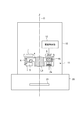
図1は、本実施形態の撮像装置の構成例を示す図である。以下の説明では、可動部が移動可能となっている光軸に垂直な面をX,Y平面と定義する。また、光軸をZ方向とする。 FIG. 1 is a diagram illustrating a configuration example of an imaging apparatus according to the present embodiment. In the following description, a plane perpendicular to the optical axis on which the movable part can move is defined as an X and Y plane. The optical axis is the Z direction.
図1に示す撮像装置は、レンズ鏡筒10とカメラ本体20とを有するカメラである。レンズ鏡筒10は、ブレ補正ユニット11と駆動制御部12とを備える。また、カメラ本体20は、撮像素子21を備える。ブレ補正ユニット11は、補正レンズL1を光軸Oに垂直な平面内でシフト移動させることによって、像ブレ補正を行う。本実施形態においては、補正レンズL1は、像ブレを補正する補正部材として機能する。レンズ鏡筒10は、補正レンズL1とともに光学系を形成するレンズ群を有している。
The imaging apparatus shown in FIG. 1 is a camera having a
撮像素子21は、レンズ鏡筒10が有する光学系により、得られる被写体の像を撮像するイメージセンサである。撮像素子21は、CCD(Charge Coupled Device )イメージセンサやCMOS(Complementary Metal Oxide Semiconductor )イメージセンサを備える。
The
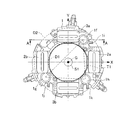
図2は、ブレ補正ユニットの分解斜視図である。図3は、ブレ補正ユニットのベース部材の上面図である。図3中には、必要に応じてベース部材1以外の部品を模式的に示している。図4は、図3に示すブレ補正ユニットのA−A位置における断面図である。図5(A)および(B)は、ベース部材およびその他の部品を模式的に表した上面図である。
FIG. 2 is an exploded perspective view of the blur correction unit. FIG. 3 is a top view of the base member of the shake correction unit. In FIG. 3, parts other than the
ブレ補正ユニット11は、補正レンズL1を光軸Oと垂直な平面内で第1の方向および、第2の方向に移動させることで、手振れなどにより生じる像振れを補正する。第1の方向(以下、X方向と記述する)と第2の方向(以下、Y方向と記述する)とは、互いに直交する方向である。
The
ブレ補正ユニット11は、補正レンズL1をX方向(第1の方向)に駆動する2つの第1駆動コイル2a,2b(図3を参照)を有する第1駆動装置群を備える。第1駆動コイル2a,2bは、補正レンズL1を挟んで互いに対向する位置に設けられた2つの駆動装置である。また、ブレ補正ユニット11は、補正レンズL1をY方向(第2の方向)に駆動する2つの第2駆動コイル3a,3bを有する第2駆動装置群を備える。第2駆動コイル3a,3bも、補正レンズL1を挟んで互いに対向する位置に設けられた2つの駆動装置である。第1駆動装置群と第2駆動装置群とは、互いに独立に駆動制御される。
The
ブレ補正ユニット11は、補正レンズL1の他に、ベース部材1、第1駆動コイル2a,2b、第2駆動コイル3a,3b、レンズホルダ4、ボール5a乃至c、引っ張りばね6a乃至c、センサホルダ7、ホール素子8a,8bを備える。なお、第1駆動コイル2a,2bを第1駆動コイル2とも記述する。第2駆動コイル3a,3bを第2駆動コイル3とも記述する。ボール5a乃至cはボール部材であり、ボール5とも記述する。引っ張りばね6a乃至cを引っ張りばね6とも記述する。
In addition to the correction lens L1, the
ベース部材1は、不図示の他のレンズ群と連動して、光軸Oに沿って移動可能に設けられている。ベース部材1は、外周部に3か所のフォロア1aを有している。フォロア1aは、不図示のカム筒に設けられたカム溝と係合し、このカム溝に倣って光軸Oに沿って移動可能となっている。
The
さらに、ベース部材1には、後述の駆動コイルを保持するコイル保持枠1b、1c,1d,1eが設けられている。コイル保持枠によって駆動コイルが固定される。また、ベース部材1には、後述のボールの転がり面となるボール受け面1f,1g,1hが設けられている。
Furthermore, the
また、ベース部材1には、後述の3つの付勢部材を係止するフック状の第1係止部1i、第2係止部1j、第3係止部1kが設けられている。各々の係止部は、後述の引っ張りばね6を係止している。
In addition, the
第1駆動コイル2a,2bは、ベース部材1に第1の方向(X方向)に2つ設けられたコイル保持枠1b,1cに保持される。第2駆動コイル3a,3bは、ベース部材1に第2の方向(Y方向)に2つ設けられたコイル保持枠1d,1eに保持される。
The first drive coils 2a and 2b are held by two
レンズホルダ4は、補正レンズL1を保持し、ベース部材1に対して光軸Oと直交する方向へ相対的に移動可能に設けられた可動部材である。レンズホルダ4は、中央に設けられたレンズ保持部4aにおいて補正レンズL1を保持する。補正レンズL1の外周部において、X軸上に、2極に着磁された磁性部材である第1マグネット4bと第2マグネット4cとが一体に形成されている。第2マグネット4cは、第1マグネット4bに対して光軸Oを挟むようにして配置されている。
The
また、補正レンズL1の外周部において、Y軸上に、2極に着磁された第3マグネット4dと第4マグネット4eが一体に成形されている。第4マグネット4eは、第3マグネット4dに対して光軸Oを挟むようにして配置されている。第1マグネット4b、4cは、第1駆動コイル2a,2bに対向する。また、第2マグネット4d,4eは、第2駆動コイル3a,3bに対向する。
Further, on the outer periphery of the correction lens L1, the
第1駆動コイル2aおよび2bに電流を流すと磁力が発生し、この磁力と第1マグネット4bおよび第2マグネット4cの磁力との関係で、反発力または吸引力をマグネットが受ける。これにより、第1マグネット4bおよび第2マグネット4cがX方向の駆動力を受けて、レンズホルダ4がX方向に平行移動することが可能となる。第1コイル2aと2bに流す電流の大きさは、同じでも構わないし、異なる大きさでも構わない。
When a current is passed through the first drive coils 2a and 2b, a magnetic force is generated, and the magnet receives a repulsive force or an attractive force due to the relationship between the magnetic force and the magnetic force of the
同様に、第2コイル3aおよび3bに電流を流すと磁力が発生し、この磁力と第3マグネット4dおよび第4マグネット4eの磁力との関係で、反発力または吸引力をマグネットが受ける。これにより、第3マグネット4dおよび第4マグネット4eがY方向の駆動力を受けて、レンズホルダ4がY方向に平行移動することが可能となる。第2コイル3aと3bに流す電流の大きさは、同じでも構わないし、異なる大きさでも構わない。
Similarly, when a current is passed through the
ベース部材1のボール受け面1f,1g,1hと対向する位置に、ボール保持枠4f,4g,4hが設けられている。ボール5は、ボール保持枠の枠内において摺動する。また、ボール保持枠は、ボール5の光軸方向の受け面にもなっている。また、ベース部材1は、引っ張りばね6を係止するフック形状からなる第1係止部4i、第2係止部4j、第3係止部4kを備えている。
3つのボール5a乃至5cは、ベース部材1とレンズホルダ4に挟まれるようにして配置される。図4には、ボール5aが示されるが、ボール5b部、5c部についても同様の構造でベース部材1とレンズホルダ4に挟まれている。
The three
図4に示すように、ベース部材1のボール受け面1fと、凹形状からなるレンズホルダ4のボール受け枠4f内の平面部とで、ボール5aが光軸方向に挟み込まれている。ベース部材1に対して、ボールによる転がり摩擦によって、レンズホルダ4は移動可能に保持されている。すなわち、ボールおよびボール受け面は、レンズホルダ4をベース部材1に対して支持する3つの支持部として機能する。そして、ボール受け面は、ボール5が摺動する摺動面として機能する。レンズホルダ4の移動に伴ってボール5aが転がり、その転がり範囲は、レンズホルダ4のボール受け枠4fの外壁(規制壁)によって規制されている。すなわち、上記摺動面の外周部に、ボール5の摺動面内での動きを規制する規制壁が設けられている。ベース部材1のボール受け面1fの大きさは、転がり範囲内でボール5aが接する範囲以上になっている。この外壁がベース部材1のボール受け面1f側にではなく、レンズホルダ4側に設けられている理由については後述する。
As shown in FIG. 4, the
引っ張りばね6は、ベース部材1とレンズホルダ4とを、ボール5を挟み込む方向すなわち光軸Oと平行な方向に付勢する付勢手段として機能する。具体的には、ベース部材1に設けられた係止部1i、1j、1kと、レンズホルダ4に設けられた係止部4i、4j、4kのそれぞれに、引っ張りばね6a,6b,6cの端部を引っかけることで付勢している。また、3つの引っ張りばね6による合力の中心位置は、3つのボール受け面を結んでできる三角形T1(後述)内に在るような配置関係になっている。
The
センサホルダ7(図1を参照)は、ホール素子8を保持しており、ベース部材1に固定される部品である。ホール素子8は、磁気を検出する磁気センサである。図2に示す第1ホール素子8aは、レンズホルダ4に形成された第1マグネット4aと所定の間隔を保って対向する位置に設置される。レンズホルダ4の移動に伴って第1マグネット4bが移動することによって起こる磁力の変化を第1ホール素子8aが検知し、レンズホルダ4のX方向の位置検出を行う。
The sensor holder 7 (see FIG. 1) is a component that holds the Hall element 8 and is fixed to the
第2ホール素子8bは、レンズホルダ4に形成された第4マグネット4eと所定の間隔を保って対向する位置に設置される。レンズホルダ4の移動に伴って第4マグネット4eが移動することによって起こる磁力の変化を第2ホール素子8bが検知し、レンズホルダ4のY方向の位置検出を行い、駆動制御部12に出力している。
The
像ブレ補正動作を行うときには、駆動制御部12は、ホール素子8が出力する信号に基づいて補正レンズL1の位置を算出する。そして、駆動制御部12は、算出した補正レンズL1の位置と、不図示の振れセンサから得た振れ情報とに基づいて補正レンズL1の駆動量を算出し、駆動電流を第1駆動コイル2および第2駆動コイル3へ供給する。
When performing the image blur correction operation, the
撮影開始時には、まず、駆動制御部12は、補正レンズL1を初期位置へ移動させるセンタリング動作を行う。初期位置とは、補正レンズL1の光軸と、光学系を形成するほかのレンズ群の光軸とが一致する位置である。このセンタリング動作を行うことにより、撮影中にブレ補正動作で補正レンズL1が移動可能な範囲がすべての方向について略等しくなり、撮影中におけるどのような振れに対しても有効な像ブレ補正動作を行える。また、像ブレ補正動作を行わない場合には、補正レンズL1を初期位置に保った状態で撮影を行う。
At the start of photographing, first, the
次に、ベース部材1に設けられたボール5のボール受け面1f,1g,1hの配置位置と、ボール部材5の転動規制となる規制壁をレンズホルダ4に設けた理由について、図3から図6を用いて詳細に説明する。
Next, the arrangement position of the
図3は、実施例1の像ブレ補正装置が備えるベース部材の上面模式図である。実施例1では、図4に示すように、ボール受け面1fは、その一部が第2駆動コイル3aと光軸方向から見て重なる位置に配置される。同様にして、ボール受け面1gは、その一部が第1駆動コイル2bと光軸方向から見て重なる位置に配置される。
FIG. 3 is a schematic top view of a base member provided in the image blur correction apparatus according to the first embodiment. In the first embodiment, as shown in FIG. 4, the
図3中に示す三角形T1は、ボール受け面1f,1g,1hのそれぞれの中心を結ぶことによってできた三角形である。点Gは、レンズホルダ4が初期位置にあるときの重心位置である。S1は、レンズホルダ4の重心位置Gがレンズホルダ4の可動範囲内における範囲である。この例では、第1駆動コイル2および第2駆動コイル3は、光軸Oを中心としたときの直径D1より外側であって、直径D2よりも内側に配置される。直径D1は、例えば、レンズホルダ4がベース部材1に対して相対的に移動するために必要な、光軸Oを中心としてベース部材1に設けられた開口の径である。直径D2は、例えば、ベース部材1の外径またはブレ補正ユニット11の外径である。また、この例では、3点の支持部として機能するボール受け面1f,1g,1hも、直径D1より外側であって、直径D2よりも内側に配置される。ブレ補正ユニットを小型にするためには、直径D2をできるだけ小さく構成できることが好ましい。
A triangle T1 shown in FIG. 3 is a triangle formed by connecting the centers of the
実施例1では、図3で示される三角形T1内に、範囲S1が入るような関係になるようにボール受け面1f、1g、1hの位置を決める。すなわち、ベース部材1を支持する3つの支持部を結ぶ三角形内に、レンズホルダ4の重心Gが含まれる。これにより、レンズホルダ4がベース部材1(固定部)に対して安定的に可動することができる。
In the first embodiment, the positions of the
ここで、図5(A)に示されるボール受け面の位置を想定する。図5(A)においては、ベース部材1を201と表記し、ボール受け面のそれぞれを201f、201g、201hと表記する。ボール受け面101f、101g、101hをコイルと光軸方向で重ならないような位置に設けようとすると、範囲S1は3つのボール受け面201f,201g,201hを結んで作られる三角形T2からはみ出すことになる。このことは、レンズホルダ4が可動して三角形T2からはみ出た位置にあるとき、安定的に支持されず、レンズホルダが傾く可能性があることを示しており、好ましくない。
Here, the position of the ball receiving surface shown in FIG. In FIG. 5A, the
また、図5(B)に示されるボール受け面の位置を想定する。図5(B)においては、ベース部材1に対応する部品をベース部材201' と表し、ボール受け面のそれぞれを201' f、201' g、201' hと表記する。図5(B)に示す例では、ボール受け面201’f乃至201’hは、駆動コイル2、3と重ならない位置で、径方向に隣接する位置に設けられている。範囲S1は、3つのボール受け面201' f,201' g,201' hを結んで作られる三角形T2' からはみ出ることなく形成可能である。しかし、図5(B)に示すベース部材201’では、ボール受け面を径方向に広げて設置しているため、ブレ補正ユニットが大型化する。
Also, assume the position of the ball receiving surface shown in FIG. In FIG. 5B, a part corresponding to the
実施例1では、図3および図4を参照して説明した位置にボール受け面が配置されている。すなわち、3つのボール受け面のうちの少なくとも1つのボール受け面は、第1駆動装置群が含む第1駆動コイル2または第2駆動装置群が含む第2駆動コイル3と光軸O方向から見て重なる位置に設けられている。これにより、ブレ補正ユニット11の小型化を図ることができ、かつ、可動可能であるレンズホルダ4を安定的に保持することができる。また、ボール受け面が駆動コイルと光軸方向から見て重なる位置にあるので、駆動コイルの大きさを確保することができ、十分な大きさのアクチュエータ出力を得ることができる。
In the first embodiment, the ball receiving surface is arranged at the position described with reference to FIGS. 3 and 4. That is, at least one of the three ball receiving surfaces is viewed from the direction of the optical axis O and the first driving coil 2 included in the first driving device group or the second driving coil 3 included in the second driving device group. Are provided at the overlapping positions. As a result, the
さらに、実施例1では、ボール受け面が駆動コイルと光軸方向で重なる領域を、駆動コイルに通電したときにマグネットの駆動方向に磁力を発生させる領域以外の領域部分としている。 Furthermore, in Example 1, the region where the ball receiving surface overlaps the drive coil in the optical axis direction is a region other than the region where magnetic force is generated in the magnet drive direction when the drive coil is energized.
図6は、駆動コイルの上面図である。Aは、マグネットの駆動方向Fに対して、駆動力を及ぼす磁力を発生させるコイルの領域である。レンズホルダ4のマグネットは領域Aに対向する大きさとし、効率よく駆動力が得られるようにしている。本実施の形態では、図6における領域Aを避けた領域においてボール受け面を設置しており、駆動マグネットの大きさを犠牲にすることなく、ボール受け面の設置が可能である。
FIG. 6 is a top view of the drive coil. A is an area of the coil that generates a magnetic force exerting a driving force with respect to the driving direction F of the magnet. The magnet of the
次に、ボール部材5の転動範囲の規制となる規制壁がレンズホルダ4側に設けられている理由について説明する。規制壁は、その壁の厚み分をボール転動部の外周部に必要である。すなわち、規制壁を設けている4f、4g、4hの光軸と直交する平面方向に必要な大きさは、ボール受け面1f、1g、1hよりも大きくなってしまう。
Next, the reason why the restriction wall that restricts the rolling range of the
本実施例では、駆動コイルの大きさのほうが、駆動コイルに対応するマグネットの大きさよりも大きい(他の実施例においても同様である)。従って、コイルを配置する部品側、すなわちベース部材1よりも、マグネットを配置する部品側、すなわちレンズホルダ4の方が、マグネット以外に使用できるスペースを確保しやすい。この理由から、本実施例では、より大きなスペースが必要なボール部材5の規制壁は、レンズホルダ4に設けられている。すなわち、規制壁は、磁性部材が配置された可動部材に設けられている。これにより、ボール受け面の設計自由度を増したり、小型化に寄与したりすることができる。
In this embodiment, the size of the drive coil is larger than the size of the magnet corresponding to the drive coil (the same applies to other embodiments). Therefore, the component side where the magnet is arranged, that is, the component side where the magnet is arranged, that is, the
また、本実施例では、3つの引っ張りばね6の付勢合力中心位置が、三角形T1の内側になるように、ボール受け面を配置している。これにより、レンズホルダ4がベース部材1に対して、さらに安定的に支持されて可動できる。
Further, in this embodiment, the ball receiving surface is arranged so that the biasing force center position of the three tension springs 6 is inside the triangle T1. Accordingly, the
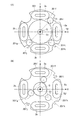
図7は、実施例2の像ブレ補正装置が備えるベース部材の上面模式図である。実施例2では、ブレ補正ユニットが、X方向、Y方向それぞれ1つの駆動コイルを備える。すなわち、ブレ補正ユニットは、合計2つのアクチュエータを備える。図3を参照して説明した実施例1の構成に比べ、アクチュエータの大きさは大きくなる。しかし、実施例2では、アクチュエータが補正レンズの外周部全体に広がらず、一部分に集約可能になる。このため、補正レンズL1の外周部に、ブレ補正ユニット以外の鏡筒構成要素を配置可能になるというメリットがある。 FIG. 7 is a schematic top view of a base member included in the image blur correction apparatus according to the second embodiment. In the second embodiment, the blur correction unit includes one drive coil in each of the X direction and the Y direction. That is, the shake correction unit includes a total of two actuators. Compared to the configuration of the first embodiment described with reference to FIG. 3, the size of the actuator is increased. However, in the second embodiment, the actuator does not spread over the entire outer peripheral portion of the correction lens, and can be integrated into a part. For this reason, there is an advantage that a lens barrel component other than the blur correction unit can be arranged on the outer periphery of the correction lens L1.
図7中に示されたもの以外の部材は、実施例1の説明において述べた部材と同じである。符号は実施例1と同様のものはそのまま用い、実施例1から変更したものについては、実施例1に対応させた符号を用いる。例えば、実施例1において1aに相当する符号は、実施例2では301aである。構成部品については、アクチュエータが2つずつから1つずつに減っただけであって、メカニズムや、その他の構成要素については、実施例1と同様であるので、実施例1と同様のものについては説明を割愛する。 Members other than those shown in FIG. 7 are the same as those described in the description of the first embodiment. The same reference numerals as those in the first embodiment are used as they are, and the reference numerals corresponding to those in the first embodiment are used for those changed from the first embodiment. For example, the code corresponding to 1a in the first embodiment is 301a in the second embodiment. As for the component parts, the number of actuators has been reduced from two to one. The mechanism and other components are the same as those in the first embodiment. I will omit the explanation.
第1コイル302aと当該第1コイル302aに対応するマグネットとが、第1の駆動装置として機能する。この第1の駆動装置は、レンズホルダ4をX方向に駆動する。また、第2コイル303aと当該第2コイル303aに対応するマグネットとが、第2の駆動装置として機能する。この第2の駆動装置は、レンズホルダ4をY方向に駆動する。第1コイル302aと第2コイル303aとは、3つの支持部のうちのいずれか1つを挟んで対向する位置に設けられている。この例では、第1コイル302aと第2コイル303aとは、ボール受け面301hを挟んで対向する位置に設けられている。
The
また、第1コイル302aによる推力中心ベクトルFx1,第2コイル303aによる推力中心ベクトルFy1は、光軸Oを通らない。つまり、実施例2では、第1コイルと第2コイルとの位置関係は、実施例1における第1コイルと第2コイルとの位置関係に比べて、互いに近い位置関係である。これにより、アクチュエータ1つあたりの大きさ(出力)をできるだけ大きくしながら、2つのアクチュエータを配置するのに必要なエリア(図7にBで示されるエリア)を小さく構成することができる。
Further, the thrust center vector Fx1 by the
さらに、本実施例では、駆動コイルとボール受け面を光軸方向から見て重なるような位置関係にする(図4を参照)。すなわち、3つのボール受け面301f乃至301hのうちの少なくとも1つ(図7に示す例では、ボール受け面301h)は、第1コイル302aまたは第2コイル303aと光軸方向から見て重なる位置に設けられている。具体的には、ボール受け面301hが、第1コイル302aおよび第2コイル303aと光軸方向から見て重なる位置に設けられている。これにより、第1コイルと第2コイルとを近づけ、ブレ補正ユニットの小型化を図ることができる。
Further, in this embodiment, the positional relationship is such that the driving coil and the ball receiving surface are overlapped when viewed from the optical axis direction (see FIG. 4). That is, at least one of the three
また、本実施例では、図7で示される三角形T3内に、範囲S1が入るような関係になるようにボール受け面301f、301g、301hの位置を決める。すなわち、ベース部材1を支持する3つの支持部を結ぶ三角形内に、レンズホルダ4の重心Gが含まれる。これにより、レンズホルダ4がベース部材301(固定部)に対して安定的に可動することができる。
In the present embodiment, the positions of the
ボール受け面301f,301g,301hの配置位置は、図7に示す配置位置に限定されない。3つのボール受け面のうちの2つを駆動コイルと重ならせるようにしてもよい。実施例2の像ブレ補正装置によれば、駆動装置の大きさを像ブレ補正装置内で、最大限大きくすることが可能でありながら、レンズホルダを安定的に保持可能なボール受け面を配置することができる。
The arrangement positions of the
図8は、実施例3の像ブレ補正装置が備えるベース部材の上面模式図である。実施例3も、実施例2と同様に、ブレ補正装置が、X方向、Y方向それぞれ1つの駆動コイルを備える。図3を参照して説明した実施例1の構成に比べ、アクチュエータ部の大きさは大きくなる。しかし、実施例3では、アクチュエータ部が補正レンズの外周部全体に広がらず、一部分に集約可能になる。このため、補正レンズL1の外周部に、ブレ補正装置以外の鏡筒構成要素を配置可能になるというメリットがある。 FIG. 8 is a schematic top view of a base member included in the image blur correction apparatus according to the third embodiment. In the third embodiment, as in the second embodiment, the shake correction apparatus includes one drive coil in each of the X direction and the Y direction. Compared with the configuration of the first embodiment described with reference to FIG. However, in the third embodiment, the actuator portion does not spread over the entire outer peripheral portion of the correction lens, and can be concentrated in part. For this reason, there is an advantage that a lens barrel component other than the shake correction device can be arranged on the outer peripheral portion of the correction lens L1.
図8中に示されたもの以外の部材は、実施例1の説明において述べた部材と同じである。符号は実施例1と同様のものはそのまま用い、実施例1から変更したものについては、実施例1に対応させた符号を用いる。例えば、実施例1において1aに相当する符号は、実施例2では401aである。構成部品については、アクチュエータ部が2つずつから1つずつに減っただけであって、メカニズムや、その他の構成要素については、実施例1と同様であるので、実施例1と同様のものについては説明を割愛する。 Members other than those shown in FIG. 8 are the same as those described in the description of the first embodiment. The same reference numerals as those in the first embodiment are used as they are, and the reference numerals corresponding to those in the first embodiment are used for those changed from the first embodiment. For example, the code corresponding to 1a in the first embodiment is 401a in the second embodiment. As for the component parts, the number of actuator parts has been reduced from two to one, and the mechanism and other components are the same as those in the first embodiment. Omits the explanation.
第1コイル402aによる推力中心ベクトルFx1,第2コイル303aによる推力中心ベクトルFy1は、光軸Oを通る。これにより、駆動コイルの大きさを最大限に大きくすることができる。
The thrust center vector Fx1 by the
駆動コイルと光軸方向から見て重ならないようにしてボール受け面を構成しようとすると、図8に示されるほど第1駆動コイル302と第2駆動コイル303を近づけることができない。従って、駆動コイルの大きさを小さくするか、補正装置自体を大きくせざるを得ない。しかしながら、実施例3では、駆動コイルとボール受け面を光軸方向から見て重なるような位置関係(図4を参照)にしたことによって、第1コイルと第2コイルを最大限近づけて配置することができる。これにより、アクチュエータ出力の高い駆動装置をもつブレ補正装置を構成することができる。 If the ball receiving surface is configured so as not to overlap the drive coil when viewed from the optical axis direction, the first drive coil 302 and the second drive coil 303 cannot be brought closer to each other as shown in FIG. Therefore, the size of the drive coil must be reduced or the correction device itself must be enlarged. However, in the third embodiment, the first coil and the second coil are arranged as close as possible by setting the positional relationship (see FIG. 4) so that the driving coil and the ball receiving surface overlap each other when viewed from the optical axis direction. be able to. As a result, it is possible to configure a shake correction device having a drive device with a high actuator output.
また、3つのボール受け面401f乃至401hのうちの少なくとも1つ(図8に示す例では、ボール受け面401h)は、第1コイル402aまたは第2コイル403aと光軸方向から見て重なる位置に設けられている。具体的には、ボール受け面401hが、第1コイル402aおよび第2コイル403aと光軸方向から見て重なる位置に設けられている。これにより、第1コイルと第2コイルとを近づけ、ブレ補正ユニットの小型化を図ることができる。
In addition, at least one of the three
また、本実施例では、図8で示される三角形T4内に、範囲S1が入るような関係になるようにボール受け面401f、401g、401hの位置を決める。すなわち、ベース部材1を支持する3つの支持部を結ぶ三角形内に、レンズホルダ4の重心Gが含まれる。これにより、レンズホルダ4がベース部材401(固定部)に対して安定的に可動することができる。
In the present embodiment, the positions of the
ボール受け面401f,401g,401hの配置位置は、図9に示す3つのボール受け面のうちの2つを駆動コイルと重ならせるようにしてもよい。ボール受け面をコイルと重なる位置に配置できることで、ボール受け面の設計自由度が増し、レンズホルダ4を安定的に保持可能な場所へ配置することができる。
As for the arrangement positions of the
実施例3の像ブレ補正装置によれば、駆動装置の大きさをブレ補正装置内で、最大限大きくすることが可能でありながら、レンズホルダを安定的に保持可能なボール受け面を配置可能となるメリットがある。 According to the image blur correction device of the third embodiment, the ball receiving surface capable of stably holding the lens holder can be disposed while the size of the driving device can be maximized within the blur correction device. There is merit to become.
以上説明した実施例に限定されることなく、種々の変形や変更が可能であって、それらも本発明の範囲内である。上述した実施例では、補正レンズL1を移動させてブレ補正動作を行う例を示したが、これに限らず、例えば、ブレ補正ユニットが、撮像素子をその撮像面に平行な面内で移動させてブレ補正を行うようにしてもよい。すなわち、撮像素子が像ブレを補正する補正部材として機能するようにしてもよい。 The present invention is not limited to the embodiments described above, and various modifications and changes are possible, and these are also within the scope of the present invention. In the above-described embodiments, an example in which the correction lens L1 is moved to perform the shake correction operation has been described. However, the present invention is not limited to this. You may make it perform blur correction. That is, the image sensor may function as a correction member that corrects image blur.
また、上述した実施例では、補正レンズL1の位置を検出する位置検出手段としてホール素子9を用いる例を示した。しかし、この位置検出手段として、例えば、MI(Magneto Impedance )センサ、磁気共鳴型磁界検出素子、MR(Magneto-Resistance)素子等、磁気を感知する他の磁気センサを用いてもよい。また、磁気センサに限らずに、光学的に位置検出を行う光センサを位置検出手段に用いてもよい。 In the above-described embodiment, the example in which the Hall element 9 is used as the position detection unit that detects the position of the correction lens L1 has been described. However, other magnetic sensors that sense magnetism, such as an MI (Magneto Impedance) sensor, a magnetic resonance type magnetic field detection element, and an MR (Magneto-Resistance) element, may be used as the position detection means. In addition to the magnetic sensor, an optical sensor that performs optical position detection may be used as the position detection means.
また、本実施形態のブレ補正ユニットを備える撮像装置として、静止画撮影を主な目的としたデジタルスチルカメラを例に挙げて説明したが、本実施形態の撮像装置は、これに限定されない。撮像装置は、例えば、フィルムカメラであってもよいし、動画撮影を主な目的とするビデオカメラであってもよいし、他の種類の撮像装置であってもよい。また、デジタル一眼レフカメラに用いられるような交換レンズのような光学機器であってもよい。 In addition, as an imaging apparatus including the shake correction unit of the present embodiment, a digital still camera mainly intended for still image shooting has been described as an example, but the imaging apparatus of the present embodiment is not limited to this. The imaging device may be, for example, a film camera, a video camera whose main purpose is moving image shooting, or another type of imaging device. Further, it may be an optical device such as an interchangeable lens used in a digital single lens reflex camera.
1 ベース部材
4 レンズホルダ
5 ボール
L1 補正レンズ
1
Claims (10)
ベース部材と、
前記補正部材を保持し、前記ベース部材に対して光軸と直交する予め決められた方向へ相対的に移動可能に設けられた可動部材と、
前記可動部材を第1の方向へ移動させる第1の駆動装置と、
前記可動部材を第2の方向へ移動させる第2の駆動装置と、
前記可動部材を前記ベース部材に対して支持する3つの支持部とを備え、
前記3つの支持部のうちの少なくとも1つの支持部は、前記第1の駆動装置または前記第2の駆動装置と光軸方向から見て重なる位置に設けられている
ことを特徴とする像ブレ補正装置。 A correction member for correcting image blur;
A base member;
A movable member that holds the correction member and is movable relative to the base member in a predetermined direction orthogonal to the optical axis;
A first driving device for moving the movable member in a first direction;
A second driving device for moving the movable member in a second direction;
Three support parts for supporting the movable member with respect to the base member,
At least one of the three support portions is provided at a position overlapping the first drive device or the second drive device as viewed from the optical axis direction. apparatus.
前記3つの支持部は、前記D1の外側かつ前記D2の内側に設けられ、
前記3つの支持部を結ぶ三角形内に、前記可動部材の重心が含まれる
ことを特徴とする請求項1に記載の像ブレ補正装置。 When the diameter of the opening provided in the base member around the optical axis, which is necessary for the movable member to move relative to the base member, is D1, and the outer diameter of the base member is D2. In addition, the first and second driving devices are provided on the outer side of the D1 and the inner side of the D2 at positions facing each other with any one of the three support portions interposed therebetween,
The three support portions are provided outside the D1 and inside the D2,
The image blur correction device according to claim 1, wherein a center of gravity of the movable member is included in a triangle connecting the three support portions.
前記ベース部材は、前記ボール部材が摺動する面であって、前記D1の外側かつ前記D2の内側に設けられた摺動面を備え、
前記摺動面の少なくとも一部が、前記第1の駆動装置または前記第2の駆動装置と光軸方向から見て重なる位置に設けられている
ことを特徴とする請求項2に記載の像ブレ補正装置。 The three support portions have ball members,
The base member is a surface on which the ball member slides, and includes a sliding surface provided outside the D1 and inside the D2.
The image blur according to claim 2, wherein at least a part of the sliding surface is provided at a position overlapping the first driving device or the second driving device when viewed from the optical axis direction. Correction device.
前記摺動面の少なくとも一部が、前記駆動コイルと光軸方向から見て重なる位置に設けられている
ことを特徴とする請求項3に記載の像ブレ補正装置。 The first and second driving devices include a driving coil and a magnetic member,
The image blur correction device according to claim 3, wherein at least a part of the sliding surface is provided at a position overlapping the driving coil when viewed from the optical axis direction.
前記摺動面の外周部に、前記ボール部材の前記摺動面内での動きを規制する規制壁が設けられており、
前記規制壁は、前記磁性部材が配置された前記可動部材に設けられている
ことを特徴とする請求項4に記載の像ブレ補正装置。 The magnetic member is disposed on the movable member;
A regulating wall for regulating movement of the ball member in the sliding surface is provided on an outer peripheral portion of the sliding surface,
The image blur correction device according to claim 4, wherein the restriction wall is provided on the movable member on which the magnetic member is disposed.
ことを特徴とする請求項1乃至5のいずれか1項に記載の像ブレ補正装置。 The first and second driving devices are arranged so that the thrust center vector of the first driving device and the thrust center vector of the second driving device do not pass through the optical axis. The image blur correction device according to any one of claims 1 to 5.
ことを特徴とする請求項1乃至5のいずれか1項に記載の像ブレ補正装置。 The first drive device and the second drive device are arranged such that a thrust center vector of the first drive device and a thrust center vector of the second drive device pass through the optical axis. The image blur correction apparatus according to any one of claims 1 to 5.
ことを特徴とする請求項1乃至7のいずれか1項に記載の像ブレ補正装置。 The image blur correction apparatus according to claim 1, wherein the second direction is a direction orthogonal to the first direction.
ことを特徴とする光学機器。 An optical apparatus comprising the image blur correction device according to claim 1.
ことを特徴とする撮像装置。 An image pickup apparatus comprising the image blur correction apparatus according to claim 1.
Priority Applications (4)
| Application Number | Priority Date | Filing Date | Title |
|---|---|---|---|
| JP2011275211A JP2013125228A (en) | 2011-12-16 | 2011-12-16 | Image blur correcting device, optical device including the same, and imaging device |
| KR1020120139331A KR20130069406A (en) | 2011-12-16 | 2012-12-04 | Image stabilization apparatus, optical apparatus, and imaging apparatus |
| US13/713,337 US9557575B2 (en) | 2011-12-16 | 2012-12-13 | Image stabilization apparatus, optical apparatus, and imaging apparatus |
| CN201210544480.9A CN103163708B (en) | 2011-12-16 | 2012-12-14 | Device for image stabilization, optical device and picture pick-up device |
Applications Claiming Priority (1)
| Application Number | Priority Date | Filing Date | Title |
|---|---|---|---|
| JP2011275211A JP2013125228A (en) | 2011-12-16 | 2011-12-16 | Image blur correcting device, optical device including the same, and imaging device |
Publications (2)
| Publication Number | Publication Date |
|---|---|
| JP2013125228A true JP2013125228A (en) | 2013-06-24 |
| JP2013125228A5 JP2013125228A5 (en) | 2015-02-05 |
Family
ID=48776475
Family Applications (1)
| Application Number | Title | Priority Date | Filing Date |
|---|---|---|---|
| JP2011275211A Pending JP2013125228A (en) | 2011-12-16 | 2011-12-16 | Image blur correcting device, optical device including the same, and imaging device |
Country Status (1)
| Country | Link |
|---|---|
| JP (1) | JP2013125228A (en) |
Cited By (4)
| Publication number | Priority date | Publication date | Assignee | Title |
|---|---|---|---|---|
| JP2014137379A (en) * | 2013-01-15 | 2014-07-28 | Olympus Corp | Blurring correction device and imaging device having the same provided |
| JP2016122049A (en) * | 2014-12-24 | 2016-07-07 | キヤノン株式会社 | Camera-shake correction unit, image capturing device, and optical device |
| JP2017090902A (en) * | 2015-11-02 | 2017-05-25 | 台湾東電化股▲ふん▼有限公司 | Electromagnetic drive module and camera device using the same |
| WO2019208227A1 (en) * | 2018-04-27 | 2019-10-31 | ミツミ電機株式会社 | Camera actuator, camera module, and camera mounting device |
Citations (4)
| Publication number | Priority date | Publication date | Assignee | Title |
|---|---|---|---|---|
| JP2007232980A (en) * | 2006-02-28 | 2007-09-13 | Samsung Electronics Co Ltd | Xy movable stage, driving control method and camera shake correcting device |
| JP2008191266A (en) * | 2007-02-01 | 2008-08-21 | Sony Corp | Image blur compensation apparatus, lens barrel and imaging apparatus |
| JP2008244708A (en) * | 2007-03-27 | 2008-10-09 | Canon Inc | Imaging apparatus and portable device |
| JP2009128841A (en) * | 2007-11-28 | 2009-06-11 | Samsung Techwin Co Ltd | Image blur correction device |
-
2011
- 2011-12-16 JP JP2011275211A patent/JP2013125228A/en active Pending
Patent Citations (4)
| Publication number | Priority date | Publication date | Assignee | Title |
|---|---|---|---|---|
| JP2007232980A (en) * | 2006-02-28 | 2007-09-13 | Samsung Electronics Co Ltd | Xy movable stage, driving control method and camera shake correcting device |
| JP2008191266A (en) * | 2007-02-01 | 2008-08-21 | Sony Corp | Image blur compensation apparatus, lens barrel and imaging apparatus |
| JP2008244708A (en) * | 2007-03-27 | 2008-10-09 | Canon Inc | Imaging apparatus and portable device |
| JP2009128841A (en) * | 2007-11-28 | 2009-06-11 | Samsung Techwin Co Ltd | Image blur correction device |
Cited By (4)
| Publication number | Priority date | Publication date | Assignee | Title |
|---|---|---|---|---|
| JP2014137379A (en) * | 2013-01-15 | 2014-07-28 | Olympus Corp | Blurring correction device and imaging device having the same provided |
| JP2016122049A (en) * | 2014-12-24 | 2016-07-07 | キヤノン株式会社 | Camera-shake correction unit, image capturing device, and optical device |
| JP2017090902A (en) * | 2015-11-02 | 2017-05-25 | 台湾東電化股▲ふん▼有限公司 | Electromagnetic drive module and camera device using the same |
| WO2019208227A1 (en) * | 2018-04-27 | 2019-10-31 | ミツミ電機株式会社 | Camera actuator, camera module, and camera mounting device |
Similar Documents
| Publication | Publication Date | Title |
|---|---|---|
| US9557575B2 (en) | Image stabilization apparatus, optical apparatus, and imaging apparatus | |
| US9348150B2 (en) | Correcting optical device and image pickup apparatus | |
| US8442393B2 (en) | Shake correction apparatus in digital camera | |
| JP5394727B2 (en) | Optical correction unit, lens barrel and imaging device | |
| JP2013156432A (en) | Lens drive device | |
| US20210173223A1 (en) | Camera module | |
| CN112954176B (en) | Image pickup element driving device and method for manufacturing image pickup element driving device | |
| JP2012133040A (en) | Correction optical device | |
| JP5266091B2 (en) | Optical correction unit, lens barrel and imaging device | |
| US9904071B2 (en) | Image blur correction device capable of preventing occurrence of image blur, lens barrel, and image pickup apparatus | |
| JP2012215650A (en) | Image blur correction device, optical instrument and imaging apparatus | |
| JP2013125228A (en) | Image blur correcting device, optical device including the same, and imaging device | |
| JP2011075834A (en) | Blur correcting device and optical apparatus | |
| JP2013125228A5 (en) | ||
| JP5289994B2 (en) | Optical correction unit, lens barrel and imaging device | |
| JP2012032526A (en) | Image blur correction device and camera | |
| JP2010054812A (en) | Shake correcting device, lens barrel, and imaging apparatus | |
| JP6057510B2 (en) | Image shake correction apparatus, optical apparatus including the same, and imaging apparatus | |
| WO2020003942A1 (en) | Lens barrel and image capturing device | |
| JP2007148023A (en) | Image blur correcting device and imaging apparatus using the same | |
| JP2014092650A (en) | Imaging unit | |
| JP2013125230A5 (en) | ||
| US11733538B2 (en) | Camera module | |
| JP2010191331A (en) | Lens driving device | |
| JP6065563B2 (en) | Position detecting device and photographing device |
Legal Events
| Date | Code | Title | Description |
|---|---|---|---|
| A521 | Request for written amendment filed |
Free format text: JAPANESE INTERMEDIATE CODE: A523 Effective date: 20141211 |
|
| A621 | Written request for application examination |
Free format text: JAPANESE INTERMEDIATE CODE: A621 Effective date: 20141211 |
|
| A977 | Report on retrieval |
Free format text: JAPANESE INTERMEDIATE CODE: A971007 Effective date: 20151014 |
|
| A131 | Notification of reasons for refusal |
Free format text: JAPANESE INTERMEDIATE CODE: A131 Effective date: 20151027 |
|
| A02 | Decision of refusal |
Free format text: JAPANESE INTERMEDIATE CODE: A02 Effective date: 20160308 |