JP2014013321A - Blur correction device, lens barrel and imaging device - Google Patents
Blur correction device, lens barrel and imaging device Download PDFInfo
- Publication number
- JP2014013321A JP2014013321A JP2012150720A JP2012150720A JP2014013321A JP 2014013321 A JP2014013321 A JP 2014013321A JP 2012150720 A JP2012150720 A JP 2012150720A JP 2012150720 A JP2012150720 A JP 2012150720A JP 2014013321 A JP2014013321 A JP 2014013321A
- Authority
- JP
- Japan
- Prior art keywords
- blur correction
- optical
- contact portion
- movable frame
- correction device
- Prior art date
- Legal status (The legal status is an assumption and is not a legal conclusion. Google has not performed a legal analysis and makes no representation as to the accuracy of the status listed.)
- Pending
Links
Images


Abstract
Description
本発明は、ブレ補正装置、レンズ鏡筒及び撮像装置に関する。 The present invention relates to a shake correction device, a lens barrel, and an imaging device.
手振れなどによる撮像画像のブレを抑制するブレ補正装置として、ブレ補正用のレンズを保持する可動枠と、当該可動枠を相対移動可能に保持する固定枠と、ブレ補正を行わない時に可動枠を固定するロックリングとを有するものが提案されている。可動枠がロックリングによってロックされることにより、ブレ補正動作が行われない場合には、ブレ補正レンズ群が光軸中心付近に固定され、撮影光学系は好適な光学特性を発揮することができる。 As a blur correction device that suppresses blurring of captured images due to camera shake, etc., a movable frame that holds a lens for blur correction, a fixed frame that holds the movable frame in a relatively movable manner, and a movable frame that is used when blur correction is not performed. One having a lock ring to be fixed has been proposed. When the movable frame is locked by the lock ring, when the blur correction operation is not performed, the blur correction lens group is fixed near the center of the optical axis, and the photographing optical system can exhibit suitable optical characteristics. .
従来では、特許文献1に示すように、駆動手段に向いて突出する突起部が、駆動手段の駆動軸上に配置されるのが通常であったため、ブレ補正装置が大型になってしまう問題があった。また、従来においては、駆動軸上に配置された1つの突起部により、可動枠を保持していたため、可動枠がガタつきやすく、光学特性に悪影響を及ぼしていた。 Conventionally, as shown in Japanese Patent Application Laid-Open No. H10-228707, since the protrusions that protrude toward the drive unit are usually arranged on the drive shaft of the drive unit, there is a problem that the shake correction device becomes large. there were. In the prior art, since the movable frame is held by a single protrusion disposed on the drive shaft, the movable frame is easily rattled and adversely affects the optical characteristics.
本発明は、コンパクトで且つ好適な光学特性を有するブレ補正装置、レンズ鏡筒及び撮像装置を提供することを目的とする。 An object of the present invention is to provide a shake correction device, a lens barrel, and an imaging device that are compact and have suitable optical characteristics.
上記目的を達成するために、本発明に係るブレ補正装置は、
撮影光学系の光軸に交差する方向に移動可能に支持された光学部材(78、74)と、前記光学部材を支持し、前記光学部材とともに前記撮影光学系の光軸に交差する方向に移動する移動部材(20)と、前記移動部材を第1の方向に移動する第1駆動部材(22、122)と、前記移動部材を前記第1の方向に交差する第2の方向に移動する第2駆動部材と(24、124)、前記移動部材の移動を規制するロック位置と、前記規制を解除する解除位置と、の間で移動するロック部材(30)とを有し、前記移動部材は、前記ロック部材が前記ロック位置にあるときに前記ロック部材に当接するとともに前記第1の方向に直交する同一直線上に配置された第1及び第2の当接部(28)を有することを特徴とする。
In order to achieve the above object, a shake correction apparatus according to the present invention includes:
An optical member (78, 74) supported so as to be movable in a direction intersecting the optical axis of the photographing optical system, and supporting the optical member and moving together with the optical member in a direction intersecting the optical axis of the photographing optical system A moving member (20) that moves, a first drive member (22, 122) that moves the moving member in a first direction, and a second direction that moves the moving member in a second direction that intersects the first direction. Two drive members (24, 124), a lock member (30) that moves between a lock position that restricts the movement of the moving member and a release position that releases the restriction, the moving member The first and second contact portions (28) are disposed on the same straight line that is in contact with the lock member when the lock member is in the lock position and orthogonal to the first direction. Features.
なお上述の説明では、本発明をわかりやすく説明するために実施形態を示す図面の符号に対応づけて説明したが、本発明は、これに限定されるものでない。後述の実施形態の構成を適宜改良してもよく、また、少なくとも一部を他の構成物に代替させてもよい。さらに、その配置について特に限定のない構成要件は、実施形態で開示した配置に限らず、その機能を達成できる位置に配置することができる。 In the above description, in order to explain the present invention in an easy-to-understand manner, the description is made in association with the reference numerals of the drawings showing the embodiments. However, the present invention is not limited to this. The configuration of the embodiment described later may be improved as appropriate, or at least a part of the configuration may be replaced with another component. Further, the configuration requirements that are not particularly limited with respect to the arrangement are not limited to the arrangement disclosed in the embodiment, and can be arranged at a position where the function can be achieved.
第1実施形態
図1は、本発明の一実施形態に係るブレ補正装置を備えるカメラ50の概略断面図である。カメラ50は、レンズ鏡筒52と、レンズ鏡筒52が装着されるカメラボディ54から成る。なお、本実施形態では、図1に示すように、レンズ鏡筒52が交換可能な一眼レフカメラ50であるが、これに限定されず、レンズ鏡筒52とカメラボディ54とが一体であるコンパクトカメラであってもよい。
First Embodiment FIG. 1 is a schematic cross-sectional view of a
本実施形態に係るレンズ鏡筒52は、6群構成のズームレンズであり、第1のレンズ群56と、第2のレンズ群58と、第3のレンズ群60と、第4のレンズ群62と、第5のレンズ群64と、第6のレンズ群66と、絞り76とを有する。
The lens barrel 52 according to this embodiment is a zoom lens having a six-group configuration, and includes a
第1のレンズ群56と、第3のレンズ群60と、第5のレンズ群64と、第6のレンズ群66は、レンズ鏡筒52の倍率調整の際に、カメラ50の光軸α方向に沿って移動する。また、第1のレンズ群56は、レンズ鏡筒52のピント合わせの際に、カメラ50の光軸α方向に沿って移動する。カメラ50は、第1のレンズ群56を移動させて焦点調整を行うことによって、カメラボディ54の内部に備えられる撮像素子74に、被写体の像を結ぶ。
The
第2のレンズ群58と、第4のレンズ群62とは、レンズ鏡筒52の倍率調整およびピント合わせの際に、光軸α方向の位置が変化しない。第2レンズ群58は、非ブレ補正レンズ群70,72と、ブレ補正レンズ群78とから成る。
The positions of the
ブレ補正レンズ群78は、ブレ補正を行うためのレンズ群であり、後述のブレ補正装置80(図2等参照)によって、光軸αに略垂直な方向に移動することができる。
The blur
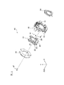
図2は、図1に示すブレ補正レンズ群78を移動させるブレ補正装置80の分解斜視図である。ブレ補正装置80は、蓋部材40、可動枠20、固定枠10、ロックリング30等を有する。図2には表示していないが、可動枠20は、その中心部にブレ補正レンズ群78を保持し、像ブレを補正するために光軸αに交差するX−Y平面上を移動することができる。以下の説明においては、光軸αと略平行な軸をZ軸、Z軸に直交して相互に垂直な軸をX軸およびY軸とする。
FIG. 2 is an exploded perspective view of the
固定枠10は、可動枠20とは異なり、X−Y平面上を移動せず、可動枠20をX−Y平面上で相対移動可能に保持する。可動枠20は、固定枠10に対して、3つの鋼球44と2つのコイルばね46を介して保持されている。可動枠20と固定枠10は、3つの鋼球44を間に挟んだ状態で、コイルばね46によって互いに押し付け合う方向に付勢されている。コイルばね46は、可動枠20と固定枠10とを光軸α方向に連結し、可動枠20と固定枠10が光軸α方向に分離することを防止する。
Unlike the
固定枠10には、ロックリング30を保持する機能を有する保持部材11が設けられている。保持部材11は、ロックリング30が固定枠10に対して光軸α方向に抜け落ちることを防止する。
The
可動枠20及び固定枠10には、VCM(ボイスコイルモータ)が設置されており、可動枠20に保持されるブレ補正レンズ群78は、VCMからの駆動力を受けて光軸αに交差するX−Y平面上を移動し、像ブレを補正する。VCMは、コイルとマグネットとから構成される。
The
本実施形態においては、第1コイル22および第2コイル24が可動枠20に設置され、第1マグネット12および第2マグネット(不図示)が固定枠10に設置される。第1コイル22と第1マグネット12とは、Z軸方向に向き合うように配置されて、第1VCMを構成し、可動枠20をX軸に沿って駆動する。第1コイル22と第1マグネット12とから構成される第1VCMは、光軸αを通りX軸に平行な第1駆動軸x1を有する(図6等参照)。第2コイル24と第2マグネットとは、Z軸方向に向き合うように配置されて、第2VCMを構成し、可動枠20をY軸に沿って駆動する。第2コイル24と第2マグネットとから構成される第2VCMは、光軸αを通りY軸に平行な第2駆動軸y1を有する(図6等参照)。
In the present embodiment, the
また、可動枠20及び固定枠10には、可動枠20の位置を検出するための位置検出センサが設置されている。レンズ鏡筒52の内部等に設置される制御部(不図示)は、角速度センサ等の検出センサによる振れの結果や、可動枠20の位置を検出する位置検出センサ等の出力を用いて、VCMの駆動及びこれに伴うブレ補正レンズ群78の移動を制御し、像ブレを補正する。
Further, the
蓋部材40は、可動枠20が光軸α方向に脱落することを防止する。蓋部材40は、固定枠10との間に、可動枠20を光軸α方向に挟み込むように配置され、ネジ47によって固定枠10に固定される。
The
ロックリング30は、略円環形状であり、ブレ補正を行わない時に、可動枠20が固定枠10に対して相対移動しないようにロックするための部材である。ロックリング30は、固定枠10に対して、光軸αを中心として相対回転可能に保持される。ロックリング30の詳細な構造については後述する。
The
図3は、図2に示す可動枠20を、固定枠10の側から観察した平面図である。可動枠20は、円筒部26を有する。円筒部26は、図2に示すように、固定枠10に向かって突出する。図3に示すように、円筒部26の外周には、半径方向外側に突出する突起部28が形成される。後述のように、突起部28とロックリング30との組み合わせにより、可動枠20のロック状態と解除状態が切り換えられる。
FIG. 3 is a plan view of the
図4は、図2に示すロックリング30を、固定枠10の側から観察した平面図である。ロックリング30は、固定枠10に取り付けられたステッピングモータやボイスコイルモータ等からの回転力を受けるギア部33を有している。
FIG. 4 is a plan view of the
ロックリング30は、ギア部33から伝えられる回転力により光軸αを中心として回転し、ロック位置(図5(A)等参照)と解除位置(図5(B)等参照)の間で変位する。またロックリング30は、回転範囲を制限するための制限部34を有している。制限部34は、ロックリング30が所定の範囲を超えて回転しようとすると固定枠10に設けられた突起に接触し、所定の範囲内のみで回転するようにロックリング30の回転範囲を制限する。
The
ロックリング30の内周面には、内周面に対して凹んでいる逃げ部39が形成される。また、逃げ部39と逃げ部39との間の内周面は、嵌合部38に形成されており、逃げ部39と嵌合部38との間には、面取り加工が施されている。嵌合部38は、逃げ部39と比較して幅広である。
A
図5(A)に示すように、ロックリング30がロック位置にある場合、嵌合部38は、可動枠20の突起部28と当接し、可動枠20の相対移動を禁止する。ロックリング30が可動枠20をガタつきなく保持するように、嵌合部38と突起部28とが当接する。
As shown in FIG. 5A, when the
図5(B)に示すように、ロックリング30がロック位置から解除位置に変位することにより、嵌合部38と突起部28との当接状態が解除される。嵌合部38の内径および突起部28の寸法は、嵌合部38と突起部28とがスムーズに摺動するように調整される。また、嵌合部38および突起部28の材質は、嵌合部38と突起部28とがスムーズに摺動するように選択される。好ましくは、嵌合部38及び突起部28の材質はポリテトラフルオロエチレン(PTFE)、ポリアセタール、または、ガラス繊維入りのポリカーボネート等である。嵌合部38とロックリング30および突起部28と可動枠20のそれぞれは、同じ材質で一体に形成してあってもよく、また、別々の材質で構成されてもよい。
As shown in FIG. 5B, when the
ロックリング30が解除位置にある場合、可動枠20の突起部28は、嵌合部38の間に形成された逃げ部39に位置し、可動枠20は、ブレ補正動作のための移動を行うことができる。可動枠20がブレ補正動作を行う際に、突起部28が嵌合部38に衝突しないように、逃げ部39の幅および深さが調整される。なお、本実施形態では、可動枠20に突起部28が形成され、ロックリング30に嵌合部38および逃げ部39が形成されているが、可動枠20に嵌合部および逃げ部が形成され、ロックリング30に突起が形成されてもよい。また、本実施形態では、突起部28は、周方向に沿って等間隔に8個配置されているが、これに限定されず、図5(C)および(D)に示すように、4個であってもよい。また、突起部28の個数は適宜決めることができる。なお、図5(C)はロック状態を示し、図5(D)は解除状態を示す。
When the
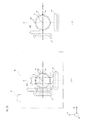
図6(A)は、カメラ50を被写体側から見た図である。図6(A)に示すように、レンズ鏡筒52の内部には、第1コイル22、第2コイル24および突起部28が、可動枠20に配置される。第1VCM(第1駆動軸x1)を構成する第1コイル22は、ブレ補正レンズ群78のX軸方向左側に配置され、第2VCM(第2駆動軸y1)を構成する第2コイル24は、ブレ補正レンズ群78のY軸方向下側に配置される。突起部28は、可動枠20の外周に略等間隔に配置されている。また、隣接する突起部28が、第1駆動軸x1または第2駆動軸y1を挟むように配置してある。なお、本実施形態では、突起部28は、周方向に沿って等間隔に配置されているが、周方向に沿って不等間隔に配置されてもよい。
FIG. 6A is a view of the
第1コイル22からレンズ中心Oまでの距離は、第1コイル22−突起部28間距離aと、突起部28−レンズ中心O間距離b1により決まる。ここで、図2に示すように、突起部28は、可動枠20から固定枠10の方向に突出する円筒部26の半径方向外側に形成されている。また、固定枠10には、第1コイル22に対向する位置に第1マグネット12が配置されている。このため、可動枠20が移動したときに、突起部28が第1マグネット12に衝突しないように、突起部28を配置する。すなわち、図6に示すように、第1マグネット12に対向する位置にある第1コイル22と突起部28との間に、所定の距離aを設けて、第1コイル22を配置する。
The distance from the
本実施形態では、図6(A)に示すように、第1駆動軸x1に直交する直線y2〜y5のそれぞれの上に、突起部28が2つずつ配置される。直線y2上に配置され隣接する突起部28は、第1コイル22に向いて突出しており、第1駆動軸x1を挟むようにして配置される。第1コイル22に向いて突出し隣接する突起部28は、好ましくは、第1駆動軸x1に対して対称に配置されるが、非対称に配置されてもよい。第1駆動軸x1と突起部28との間の角度θは、90度未満であり、好ましくは、0度〜45度であり、更に好ましくは、22.5度である。なお、直線y3〜y5上に配置される突起部28も、直線y2上に配置される突起部28と同様に、第1駆動軸x1に対して対称に配置される。
In the present embodiment, as shown in FIG. 6A, two
本実施形態では、第1駆動軸x1を挟むようにして、第1コイル22に向いて突出する突起部28を配置してあるので、レンズ中心Oから突起部28までの距離b1を短くすることができる。したがって、本実施形態では、レンズ中心Oから第1コイル22までの距離(a+b1)を短くすることができるので、可動枠20を小型化することができ、コンパクトなブレ補正装置を提供することができる。
In the present embodiment, since the protruding
これに対して、従来においては、図6(B)に示すように、第1コイル22に向いて突出する突起部28が、第1駆動軸x1上に配置されるのが通常であった。このため、従来技術においては、レンズ中心Oから突起部28までの距離b2が長くなってしまうので、レンズ中心Oから第1コイル22までの距離(a+b2)も長くなってしまい、可動枠20がその分大きくなってしまっていた。
On the other hand, conventionally, as shown in FIG. 6 (B), it is usual that the
図6(A)に示すように、第2駆動軸y1に直交する直線x2〜x5のそれぞれの上にも、突起部28が2つずつ配置される。直線x5上に配置され隣接する突起部28は、第2コイル24に向いて突出しており、第2駆動軸y1を挟むようにして、第2駆動軸y1に対して対称に配置されている。このため、第2コイル24との関係においても、上記の第1コイル22との関係と同様に、レンズ中心Oから第2コイル24までの距離を短くすることができるので、コンパクトなブレ補正装置を実現することができる。なお、直線x2〜x4上に配置される突起部28も、直線x5上に配置される突起部28と同様に、第2駆動軸y1に対して対称に配置される。
As shown in FIG. 6A, two
また、本実施形態によれば、可動枠20をロックリング30でロックした場合において、可動枠20を安定に保持することができる。なぜなら、カメラ50による撮影を行う場合において、撮影者は、通常は、図6(A)に示すように、カメラ50を水平に構えて撮影を行い、もしくは、カメラ50を90度傾けて垂直に構えて撮影を行う。
Further, according to the present embodiment, when the
カメラ50を水平に構えて撮影するときには、第2駆動軸y1と重力方向とがほぼ同じ方向になり、図5(A)および図6(A)に示すように、重力方向の最も下側に位置して第2駆動軸y1を挟んで隣接する2つの突起部28がロック部材に当接する。このため、本実施形態では、第2駆動軸y1を挟んで隣接する2つの突起部28によって、可動枠20がロックリング30に安定に保持される。したがって、本実施形態によれば、可動枠20を安定に設計位置に保持し、好適な光学特性を提供することができる。
When shooting with the
また、カメラ50を90度傾けて垂直に構えて撮影するときには、第1駆動軸x1と重力方向とがほぼ同じ方向になり、このときも、重力方向の最も下側に位置して第1駆動軸x1を挟んで隣接する2つの突起部28がロック部材に当接するので、好適な光学特性を提供することができる。
Further, when shooting with the
これに対して、従来においては、図6(B)に示すように、カメラを水平に構えて撮影する場合、またはカメラを垂直に構えて撮影する場合において、突起部28が、重力方向に向いて1つ配置されていた。このため、従来においては、可動枠をロックリングでロックして撮影を行う際に、可動枠がガタつきやすく、光学特性に悪影響を及ぼしていた。
On the other hand, conventionally, as shown in FIG. 6B, when shooting with the camera held horizontally or when shooting with the camera held vertically, the
第2実施形態
第2実施形態では、図7に示すように、第1マグネット122および第2マグネット124が可動枠20に設置される以外は第1実施形態と同様である。以下の説明において、上記の実施形態と重複する部分の説明を省略する。
Second Embodiment The second embodiment is the same as the first embodiment except that the
本実施形態では、固定枠10に、第1コイルおよび第2コイルが設置される(不図示)。第1コイルと第1マグネット122とは、Z軸方向に向き合うように配置されて、第1VCMを構成し、第2コイル24と第2マグネットとは、Z軸方向に向き合うように配置されて、第2VCMを構成する。
In the present embodiment, the first coil and the second coil are installed on the fixed frame 10 (not shown). The first coil and the
第1マグネット122からレンズ中心Oまでの距離は、第1マグネット122−突起部28間距離cと、突起部28−レンズ中心O間距離b1により決まる。ここで、図2に示すように、突起部28は、可動枠20から固定枠10に向かって突出する円筒部26の半径方向外側に形成されている。また、固定枠10には、第1コイルが配置されている。このため、可動枠20が移動したときに、突起部28が第1コイルに衝突しないように、突起部28を配置する。すなわち、第1コイルに対向する位置にある第1マグネット122と突起部28との間に、所定の距離cを設けて、第1マグネット122を配置する。
The distance from the
なお、本発明は、上記の実施形態に限定されない。 In addition, this invention is not limited to said embodiment.
上記の実施形態では、図1に示すブレ補正レンズ群78を駆動するタイプのレンズ移動型ブレ補正装置であるが、これに限定されず、図1に示す撮像素子74が移動するタイプの撮像素子移動型ブレ補正装置にも適用することができる。
In the above-described embodiment, the lens movement type blur correction device of the type that drives the blur
また、上記の実施形態で説明したブレ補正装置は、コンパクトデジタルカメラや一眼レフデジタルカメラに限らず、ビデオカメラ、双眼鏡、顕微鏡、望遠鏡、携帯電話などの光学機器にも適用することができる。 The blur correction apparatus described in the above embodiment can be applied not only to a compact digital camera and a single-lens reflex digital camera but also to an optical apparatus such as a video camera, binoculars, a microscope, a telescope, and a mobile phone.
10…固定枠
11…弾性部材
12…第1マグネット
16…第3面
20…可動枠
22…第1コイル
24…第2コイル
26…円筒部
28…突起部
30…ロックリング
33…ギア部
34…制限部
38…嵌合部
39…逃げ部
40…蓋部材
44…鋼球
46…コイルばね
47…ネジ
50…カメラ
52…レンズ鏡筒
54…カメラボディ
56〜66…第1〜第6のレンズ群
70,72…非ブレ補正レンズ群
74…撮像素子
76…絞り
78…ブレ補正レンズ群
80…ブレ補正装置
α…光軸
DESCRIPTION OF
Claims (11)
前記光学部材を支持し、前記光学部材とともに前記撮影光学系の光軸に交差する方向に移動する移動部材と、
前記移動部材を第1の方向に移動する第1駆動部材と、
前記移動部材を前記第1の方向に交差する第2の方向に移動する第2駆動部材と、
前記移動部材の移動を規制するロック位置と、前記規制を解除する解除位置と、の間で移動するロック部材とを有し、
前記移動部材は、前記ロック部材が前記ロック位置にあるときに前記ロック部材に当接するとともに前記第1の方向に直交する同一直線上に配置された第1及び第2の当接部を有することを特徴とするブレ補正装置。 An optical member supported so as to be movable in a direction intersecting the optical axis of the photographing optical system;
A moving member that supports the optical member and moves together with the optical member in a direction intersecting the optical axis of the photographing optical system;
A first drive member that moves the moving member in a first direction;
A second drive member that moves the moving member in a second direction that intersects the first direction;
A lock position that restricts movement of the moving member; and a lock member that moves between a release position that releases the restriction;
The moving member has first and second abutting portions that are in contact with the locking member when the locking member is in the locking position and are arranged on the same straight line perpendicular to the first direction. A blur correction device characterized by the above.
前記第1の当接部と前記第2の当接部は、前記第1の駆動軸に対して対称に配置されていることを特徴とする請求項2に記載のブレ補正装置。 The blur correction device according to claim 2,
The blur correction apparatus according to claim 2, wherein the first contact portion and the second contact portion are arranged symmetrically with respect to the first drive shaft.
前記移動部材は、前記第2の方向に直交する同一直線上に配置された第3及び第4の当接部を有することを特徴とする請求項1から3のいずれか一項に記載のブレ補正装置。 The first direction and the second direction are orthogonal to each other;
The said moving member has the 3rd and 4th contact part arrange | positioned on the same straight line orthogonal to the said 2nd direction, The blurring as described in any one of Claim 1 to 3 characterized by the above-mentioned. Correction device.
前記第3の当接部と前記第4の当接部は、前記第2の駆動軸に対して対称に配置されていることを特徴とする請求項5に記載のブレ補正装置。 The shake correction apparatus according to claim 5,
The blur correction device according to claim 5, wherein the third contact portion and the fourth contact portion are arranged symmetrically with respect to the second drive shaft.
Priority Applications (1)
| Application Number | Priority Date | Filing Date | Title |
|---|---|---|---|
| JP2012150720A JP2014013321A (en) | 2012-07-04 | 2012-07-04 | Blur correction device, lens barrel and imaging device |
Applications Claiming Priority (1)
| Application Number | Priority Date | Filing Date | Title |
|---|---|---|---|
| JP2012150720A JP2014013321A (en) | 2012-07-04 | 2012-07-04 | Blur correction device, lens barrel and imaging device |
Publications (2)
| Publication Number | Publication Date |
|---|---|
| JP2014013321A true JP2014013321A (en) | 2014-01-23 |
| JP2014013321A5 JP2014013321A5 (en) | 2015-08-06 |
Family
ID=50109032
Family Applications (1)
| Application Number | Title | Priority Date | Filing Date |
|---|---|---|---|
| JP2012150720A Pending JP2014013321A (en) | 2012-07-04 | 2012-07-04 | Blur correction device, lens barrel and imaging device |
Country Status (1)
| Country | Link |
|---|---|
| JP (1) | JP2014013321A (en) |
Cited By (1)
| Publication number | Priority date | Publication date | Assignee | Title |
|---|---|---|---|---|
| JP2016122049A (en) * | 2014-12-24 | 2016-07-07 | キヤノン株式会社 | Camera-shake correction unit, image capturing device, and optical device |
Citations (4)
| Publication number | Priority date | Publication date | Assignee | Title |
|---|---|---|---|---|
| JPH0887046A (en) * | 1994-09-19 | 1996-04-02 | Canon Inc | Image blurring correcting device |
| JPH08211436A (en) * | 1995-02-02 | 1996-08-20 | Canon Inc | Shake correction means locking device |
| JP2008026432A (en) * | 2006-07-19 | 2008-02-07 | Matsushita Electric Ind Co Ltd | Image blur correcting device, interchangeable lens equipped therewith, camera system and control method for image blur correcting device |
| JP2010015107A (en) * | 2008-07-07 | 2010-01-21 | Olympus Imaging Corp | Imaging apparatus to correct blurring |
-
2012
- 2012-07-04 JP JP2012150720A patent/JP2014013321A/en active Pending
Patent Citations (4)
| Publication number | Priority date | Publication date | Assignee | Title |
|---|---|---|---|---|
| JPH0887046A (en) * | 1994-09-19 | 1996-04-02 | Canon Inc | Image blurring correcting device |
| JPH08211436A (en) * | 1995-02-02 | 1996-08-20 | Canon Inc | Shake correction means locking device |
| JP2008026432A (en) * | 2006-07-19 | 2008-02-07 | Matsushita Electric Ind Co Ltd | Image blur correcting device, interchangeable lens equipped therewith, camera system and control method for image blur correcting device |
| JP2010015107A (en) * | 2008-07-07 | 2010-01-21 | Olympus Imaging Corp | Imaging apparatus to correct blurring |
Cited By (1)
| Publication number | Priority date | Publication date | Assignee | Title |
|---|---|---|---|---|
| JP2016122049A (en) * | 2014-12-24 | 2016-07-07 | キヤノン株式会社 | Camera-shake correction unit, image capturing device, and optical device |
Similar Documents
| Publication | Publication Date | Title |
|---|---|---|
| JP5109450B2 (en) | Blur correction device and optical apparatus | |
| US9335560B2 (en) | Imaging apparatus | |
| JP6989254B2 (en) | Optical module and optical unit | |
| JP4415281B2 (en) | Lens barrel and imaging device | |
| US20150195460A1 (en) | Image stabilizer, lens apparatus, and image pickup apparatus | |
| JP2008058391A (en) | Imaging lens unit and imaging apparatus | |
| JP2012203319A (en) | Correction apparatus for image blurring and imaging apparatus | |
| JP5495860B2 (en) | Optical image stabilizer and optical apparatus | |
| JP2008233385A (en) | Blur preventing device, lens barrel and optical apparatus | |
| KR102581965B1 (en) | camera module | |
| JP2015121755A (en) | Image shake correction device, lens device, and imaging device | |
| KR20130044438A (en) | Hand trembling compensation actuator and camera module containing the same | |
| JP2016114861A (en) | Lens barrel and optical device | |
| JP2008209435A (en) | Camera-shake correcting device and optical device | |
| US9400369B2 (en) | Optical apparatus | |
| JP5262172B2 (en) | Blur correction device and optical apparatus | |
| JP2022136419A (en) | Optical unit with shake correction function | |
| JP5544900B2 (en) | Optical apparatus and optical apparatus | |
| US11825199B2 (en) | Driving device capable of properly restricting translational movement and rotational movement, image capturing apparatus, and method of controlling driving device | |
| JP2014013321A (en) | Blur correction device, lens barrel and imaging device | |
| JP6051045B2 (en) | Light amount adjusting device and optical apparatus | |
| JP2013045068A (en) | Vibration-proof actuator, lens unit with the same, and camera | |
| JP2016184102A (en) | Zoom lens device and control method for the same | |
| JP2019008078A (en) | Lens body tube | |
| US20230367094A1 (en) | Driving apparatus and lens apparatus having the same |
Legal Events
| Date | Code | Title | Description |
|---|---|---|---|
| A521 | Written amendment |
Free format text: JAPANESE INTERMEDIATE CODE: A523 Effective date: 20150619 |
|
| A621 | Written request for application examination |
Free format text: JAPANESE INTERMEDIATE CODE: A621 Effective date: 20150619 |
|
| A977 | Report on retrieval |
Free format text: JAPANESE INTERMEDIATE CODE: A971007 Effective date: 20160525 |
|
| A131 | Notification of reasons for refusal |
Free format text: JAPANESE INTERMEDIATE CODE: A131 Effective date: 20160531 |
|
| A02 | Decision of refusal |
Free format text: JAPANESE INTERMEDIATE CODE: A02 Effective date: 20161206 |