JP6592449B2 - Container for framework elements - Google Patents
Container for framework elements Download PDFInfo
- Publication number
- JP6592449B2 JP6592449B2 JP2016555663A JP2016555663A JP6592449B2 JP 6592449 B2 JP6592449 B2 JP 6592449B2 JP 2016555663 A JP2016555663 A JP 2016555663A JP 2016555663 A JP2016555663 A JP 2016555663A JP 6592449 B2 JP6592449 B2 JP 6592449B2
- Authority
- JP
- Japan
- Prior art keywords
- container
- wheels
- scaffold
- base
- assembly
- Prior art date
- Legal status (The legal status is an assumption and is not a legal conclusion. Google has not performed a legal analysis and makes no representation as to the accuracy of the status listed.)
- Expired - Fee Related
Links
Images


Classifications
-
- E—FIXED CONSTRUCTIONS
- E04—BUILDING
- E04G—SCAFFOLDING; FORMS; SHUTTERING; BUILDING IMPLEMENTS OR AIDS, OR THEIR USE; HANDLING BUILDING MATERIALS ON THE SITE; REPAIRING, BREAKING-UP OR OTHER WORK ON EXISTING BUILDINGS
- E04G5/00—Component parts or accessories for scaffolds
- E04G5/004—Storage and transport racks for scaffolding components
-
- B—PERFORMING OPERATIONS; TRANSPORTING
- B65—CONVEYING; PACKING; STORING; HANDLING THIN OR FILAMENTARY MATERIAL
- B65D—CONTAINERS FOR STORAGE OR TRANSPORT OF ARTICLES OR MATERIALS, e.g. BAGS, BARRELS, BOTTLES, BOXES, CANS, CARTONS, CRATES, DRUMS, JARS, TANKS, HOPPERS, FORWARDING CONTAINERS; ACCESSORIES, CLOSURES, OR FITTINGS THEREFOR; PACKAGING ELEMENTS; PACKAGES
- B65D19/00—Pallets or like platforms, with or without side walls, for supporting loads to be lifted or lowered
- B65D19/0004—Rigid pallets without side walls
-
- B—PERFORMING OPERATIONS; TRANSPORTING
- B65—CONVEYING; PACKING; STORING; HANDLING THIN OR FILAMENTARY MATERIAL
- B65D—CONTAINERS FOR STORAGE OR TRANSPORT OF ARTICLES OR MATERIALS, e.g. BAGS, BARRELS, BOTTLES, BOXES, CANS, CARTONS, CRATES, DRUMS, JARS, TANKS, HOPPERS, FORWARDING CONTAINERS; ACCESSORIES, CLOSURES, OR FITTINGS THEREFOR; PACKAGING ELEMENTS; PACKAGES
- B65D19/00—Pallets or like platforms, with or without side walls, for supporting loads to be lifted or lowered
- B65D19/38—Details or accessories
- B65D19/40—Elements for spacing platforms from supporting surface
- B65D19/42—Arrangements or applications of rollers or wheels
-
- E—FIXED CONSTRUCTIONS
- E04—BUILDING
- E04G—SCAFFOLDING; FORMS; SHUTTERING; BUILDING IMPLEMENTS OR AIDS, OR THEIR USE; HANDLING BUILDING MATERIALS ON THE SITE; REPAIRING, BREAKING-UP OR OTHER WORK ON EXISTING BUILDINGS
- E04G1/00—Scaffolds primarily resting on the ground
- E04G1/14—Comprising essentially pre-assembled two-dimensional frame-like elements, e.g. of rods in L- or H-shape, with or without bracing
-
- E—FIXED CONSTRUCTIONS
- E04—BUILDING
- E04G—SCAFFOLDING; FORMS; SHUTTERING; BUILDING IMPLEMENTS OR AIDS, OR THEIR USE; HANDLING BUILDING MATERIALS ON THE SITE; REPAIRING, BREAKING-UP OR OTHER WORK ON EXISTING BUILDINGS
- E04G1/00—Scaffolds primarily resting on the ground
- E04G1/15—Scaffolds primarily resting on the ground essentially comprising special means for supporting or forming platforms; Platforms
-
- E—FIXED CONSTRUCTIONS
- E04—BUILDING
- E04G—SCAFFOLDING; FORMS; SHUTTERING; BUILDING IMPLEMENTS OR AIDS, OR THEIR USE; HANDLING BUILDING MATERIALS ON THE SITE; REPAIRING, BREAKING-UP OR OTHER WORK ON EXISTING BUILDINGS
- E04G1/00—Scaffolds primarily resting on the ground
- E04G1/17—Comprising essentially pre-assembled three-dimensional elements, e.g. cubic elements
-
- E—FIXED CONSTRUCTIONS
- E04—BUILDING
- E04G—SCAFFOLDING; FORMS; SHUTTERING; BUILDING IMPLEMENTS OR AIDS, OR THEIR USE; HANDLING BUILDING MATERIALS ON THE SITE; REPAIRING, BREAKING-UP OR OTHER WORK ON EXISTING BUILDINGS
- E04G1/00—Scaffolds primarily resting on the ground
- E04G1/18—Scaffolds primarily resting on the ground adjustable in height
-
- E—FIXED CONSTRUCTIONS
- E04—BUILDING
- E04G—SCAFFOLDING; FORMS; SHUTTERING; BUILDING IMPLEMENTS OR AIDS, OR THEIR USE; HANDLING BUILDING MATERIALS ON THE SITE; REPAIRING, BREAKING-UP OR OTHER WORK ON EXISTING BUILDINGS
- E04G1/00—Scaffolds primarily resting on the ground
- E04G1/24—Scaffolds primarily resting on the ground comprising essentially special base constructions; comprising essentially special ground-engaging parts, e.g. inclined struts, wheels
-
- E—FIXED CONSTRUCTIONS
- E04—BUILDING
- E04G—SCAFFOLDING; FORMS; SHUTTERING; BUILDING IMPLEMENTS OR AIDS, OR THEIR USE; HANDLING BUILDING MATERIALS ON THE SITE; REPAIRING, BREAKING-UP OR OTHER WORK ON EXISTING BUILDINGS
- E04G11/00—Forms, shutterings, or falsework for making walls, floors, ceilings, or roofs
- E04G11/36—Forms, shutterings, or falsework for making walls, floors, ceilings, or roofs for floors, ceilings, or roofs of plane or curved surfaces end formpanels for floor shutterings
- E04G11/38—Forms, shutterings, or falsework for making walls, floors, ceilings, or roofs for floors, ceilings, or roofs of plane or curved surfaces end formpanels for floor shutterings for plane ceilings of concrete
-
- E—FIXED CONSTRUCTIONS
- E04—BUILDING
- E04G—SCAFFOLDING; FORMS; SHUTTERING; BUILDING IMPLEMENTS OR AIDS, OR THEIR USE; HANDLING BUILDING MATERIALS ON THE SITE; REPAIRING, BREAKING-UP OR OTHER WORK ON EXISTING BUILDINGS
- E04G11/00—Forms, shutterings, or falsework for making walls, floors, ceilings, or roofs
- E04G11/36—Forms, shutterings, or falsework for making walls, floors, ceilings, or roofs for floors, ceilings, or roofs of plane or curved surfaces end formpanels for floor shutterings
- E04G11/48—Supporting structures for shutterings or frames for floors or roofs
-
- E—FIXED CONSTRUCTIONS
- E04—BUILDING
- E04G—SCAFFOLDING; FORMS; SHUTTERING; BUILDING IMPLEMENTS OR AIDS, OR THEIR USE; HANDLING BUILDING MATERIALS ON THE SITE; REPAIRING, BREAKING-UP OR OTHER WORK ON EXISTING BUILDINGS
- E04G25/00—Shores or struts; Chocks
-
- E—FIXED CONSTRUCTIONS
- E04—BUILDING
- E04G—SCAFFOLDING; FORMS; SHUTTERING; BUILDING IMPLEMENTS OR AIDS, OR THEIR USE; HANDLING BUILDING MATERIALS ON THE SITE; REPAIRING, BREAKING-UP OR OTHER WORK ON EXISTING BUILDINGS
- E04G5/00—Component parts or accessories for scaffolds
- E04G5/16—Struts or stiffening rods, e.g. diagonal rods
-
- B—PERFORMING OPERATIONS; TRANSPORTING
- B65—CONVEYING; PACKING; STORING; HANDLING THIN OR FILAMENTARY MATERIAL
- B65D—CONTAINERS FOR STORAGE OR TRANSPORT OF ARTICLES OR MATERIALS, e.g. BAGS, BARRELS, BOTTLES, BOXES, CANS, CARTONS, CRATES, DRUMS, JARS, TANKS, HOPPERS, FORWARDING CONTAINERS; ACCESSORIES, CLOSURES, OR FITTINGS THEREFOR; PACKAGING ELEMENTS; PACKAGES
- B65D2519/00—Pallets or like platforms, with or without side walls, for supporting loads to be lifted or lowered
- B65D2519/00004—Details relating to pallets
- B65D2519/00736—Details
- B65D2519/00776—Accessories for manipulating the pallet
- B65D2519/00781—Accessories for manipulating the pallet for moving on a surface, e.g. wheels, pads
-
- E—FIXED CONSTRUCTIONS
- E04—BUILDING
- E04G—SCAFFOLDING; FORMS; SHUTTERING; BUILDING IMPLEMENTS OR AIDS, OR THEIR USE; HANDLING BUILDING MATERIALS ON THE SITE; REPAIRING, BREAKING-UP OR OTHER WORK ON EXISTING BUILDINGS
- E04G1/00—Scaffolds primarily resting on the ground
- E04G1/24—Scaffolds primarily resting on the ground comprising essentially special base constructions; comprising essentially special ground-engaging parts, e.g. inclined struts, wheels
- E04G2001/242—Scaffolds movable on wheels or tracks
Landscapes
- Engineering & Computer Science (AREA)
- Architecture (AREA)
- Mechanical Engineering (AREA)
- Civil Engineering (AREA)
- Structural Engineering (AREA)
- Pallets (AREA)
- Conveying And Assembling Of Building Elements In Situ (AREA)
- Supports Or Holders For Household Use (AREA)
Description
本出願は、2014年3月4日を出願日とする「A STILLAGE FOR FRAMEWORK ELEMENTS」というタイトルのオーストラリア特許仮出願第2014900722号を基礎とする優先権を主張するものであり、この出願の内容は、引用により本明細書の一部とする。
次の同時係属出願は、以下の明細書の記載中で参照される。
・オーストラリア特許仮出願第2012903312号を基礎とする優先権を主張し、2013年8月2日を国際出願日とする「FORMWORK SUPPORT ELEMENT」というタイトルの国際特許出願PCT/AU2013/000855。
この出願の内容は、引用により本発明の一部とする。
本発明は、コンテナ組立体に関する。本発明は、特定の形態として、コンクリート型枠及び/またはそのような型枠を支持するための支柱または足場システムの要素のためのコンテナ組立体に関する。
This application claims priority based on Australian Patent Provisional Application No. 20144900722, entitled “A STILLAGE FOR FRAMEWORK ELEMENTS”, filed on March 4, 2014. And incorporated herein by reference.
The next co-pending application is referenced in the description of the following specification.
An international patent application PCT / AU2013 / 000855 entitled “FORMWORK SUPPORT ELEMENT”, claiming priority based on Australian Provisional Patent Application No. 201209312 and having an international filing date of August 2, 2013.
The contents of this application are hereby incorporated by reference.
The present invention relates to a container assembly. The present invention relates in particular to a container assembly for a concrete formwork and / or a post or scaffold system element for supporting such a formwork.
建物の建設中に、コンクリート建築物においては型枠が用いられ、この型枠は、例えば床スラブや梁等の要素の形成のために濡れた状態のコンクリートを流し込むことができる型または表面を提供する。床スラブの場合、複数階の建物の床が連続して形成されること、及びその後により高い階を形成するために前の床の上に型枠が配置されることが一般的である。 During building construction, formwork is used in concrete buildings, which provide a mold or surface into which wet concrete can be poured to form elements such as floor slabs and beams. To do. In the case of floor slabs, it is common for the floors of a multi-story building to be formed continuously, and then formwork is placed on the previous floor to form a higher floor.
通常、支柱または足場システムが、ロスト(すなわち再利用できない)型枠、またはひとたびコンクリートが硬化されたときコンクリートスラブから取り外され、再利用され得る型枠のいずれかを含む立設型を支持するために用いられる。再使用可能な型枠は、足場の最上部で保持されるアルミニウムの型枠パンを含み得る。加えて、シートまたはボードをフレームワークの上で用いてもよい。 Typically, a column or scaffold system supports a standing (including non-reusable) formwork, or a standing form that includes a formwork that can be removed and reused from a concrete slab once the concrete is cured. Used for. The reusable formwork may include an aluminum formwork pan that is held on top of the scaffold. In addition, sheets or boards may be used on the framework.
支持足場システム、更には型枠を組み立てるプロセスでは、第一に多数の要素(部品)をそれらが必要な高さ位置まで持ち上げる必要がある。これは一般的にはパレットを用いて行われる。パレットは、フォークリフトまたはパレットジャッキを用いて一度に1つずつ動かされ、積み下ろされたパレットは、移動され、必要になるまで保管されなければならないので、これが問題になる。 In the process of assembling the support scaffold system and even the formwork, it is first necessary to lift a large number of elements (parts) to the required height position. This is typically done using a pallet. This is a problem because the pallets are moved one at a time using a forklift or pallet jack, and the unloaded pallets must be moved and stored until needed.
本発明は、このような背景及びそれに関連する問題や課題に対して開発されたものである。 The present invention has been developed for such a background and related problems and problems.
本発明の一定の目的及び利点は、例示の目的で本発明の実施形態が開示された、添付の図面を参照した後述の説明からより明白となろう。 Certain objects and advantages of the present invention will become more apparent from the following description, taken in conjunction with the accompanying drawings, in which embodiments of the invention are disclosed for purposes of illustration.
本発明の第1の態様によれば、足場組立体用の部品のためのコンテナであって、前記足場組立体の少なくとも1つの部品のための少なくとも1つの取り付け点を含み、使用の際に、前記部品がその使用位置にあるときには、前記部品の少なくとも一部分が前記取り付け点に係合可能であり、前記部品の不使用時には、前記コンテナが前記部品を運搬するように適合されていることを特徴とするコンテナが提供される。 According to a first aspect of the present invention, a container for parts for a scaffold assembly, comprising at least one attachment point for at least one part of said scaffold assembly, in use, At least a portion of the component is engageable with the attachment point when the component is in its use position, and the container is adapted to carry the component when the component is not in use. Is provided.
一形態では、前記部品が、直立部部品(支柱)である。 In one form, the said component is an upright part component (support | pillar).
一形態では、前記コンテナが、各直立部部品のための取り付け点を含む。 In one form, the container includes an attachment point for each upright part.
一形態では、前記足場組立体が、平面な形態で実質的に矩形であり、その各角部にまたは各角部の近傍に各直立部部品を含み、前記コンテナが、ベース部を含み、前記ベース部が、平面的な形態で実質的に矩形であり、平面的な形態の前記足場組立体の前記複数の直立部部品の位置に一致するように、前記複数の直立部部品の各々と協働して配置される取り付け点を含む。 In one form, the scaffold assembly is substantially rectangular in a planar configuration and includes each upright part at or near each corner thereof, and the container includes a base, A base portion is substantially rectangular in a planar configuration and cooperates with each of the plurality of upright components so as to coincide with the position of the plurality of upright components of the scaffold assembly in a planar configuration. Includes attachment points that are operatively arranged.
前記ベース部が、支持足場構造と協働するように構成されていることは、上記の内容から明らかであろう。 It will be apparent from the foregoing that the base is configured to cooperate with the support scaffold structure.
一形態では、各取り付け点が、通孔を含む。 In one form, each attachment point includes a through hole.
一形態では、各通孔は、1つの直立部部品の上側端を受容するように適合されている。 In one form, each through hole is adapted to receive the upper end of one upright part.
一形態では、各通孔は、1つの直立部部品の下側端を受容するように適合されている。 In one form, each through hole is adapted to receive the lower end of one upright part.
一形態では、前記足場組立体の各直立部部品の上側端は、前記コンテナの下から取り付け点を通して受容可能である。 In one form, the upper end of each upright part of the scaffold assembly is receivable through a mounting point from under the container.
一形態では、使用に際して、前記足場組立体の各直立部部品の下側端が、前記コンテナの上から取り付け点を通して受容され、かつ各々が、前記コンテナが支持される床面または地面の上まで延びる。このようにして、前記コンテナは、前記足場組立体を支持することなく足場組立体のフットプリント内に保管することができる。 In one form, in use, the lower end of each upright part of the scaffold assembly is received from above the container through a mounting point and each is above the floor or ground on which the container is supported. Extend. In this way, the container can be stored within the footprint of the scaffold assembly without supporting the scaffold assembly.
一形態では、使用に際して、前記足場組立体の各直立部部品の上側端が、前記コンテナの下から取り付け点を通して受容されるとき、前記コンテナは前記直立部部品によって支持されるプラットフォームを形成する。 In one form, in use, when the upper end of each upright part of the scaffold assembly is received through a mounting point from below the container, the container forms a platform supported by the upright part.
一形態では、前記コンテナは、ベース部と、前記ベース部の下から下がる複数の車輪とを更に含み、前記コンテナは、前記車輪上で回動可能である。 In one form, the container further includes a base part and a plurality of wheels descending from below the base part, and the container is rotatable on the wheel.
一形態では、前記コンテナは、連結手段を更に含み、前記連結手段を介して前記コンテナの列を形成可能である。 In one form, the container further includes connecting means, through which the container row can be formed.
一形態では、前記ベース部が一対のフォークリフトタインを受容するように適合されている。 In one form, the base is adapted to receive a pair of forklift tines.
一形態では、前記コンテナは、少なくとも1つの持ち上げ点を更に含み、前記持ち上げ点を介して前記コンテナがクレーンで持ち上げ可能である。 In one form, the container further comprises at least one lifting point through which the container can be lifted by a crane.
一形態では、前記コンテナが、前記ベース部に対して前記足場組立体のフレームワーク要素を固定するための手段を更に含む。 In one form, the container further includes means for securing a framework element of the scaffold assembly to the base.
一形態では、前記コンテナが、前記ベース部の一対の側部に沿って取り付けられる側壁と、前記ベース部の一対の端部に沿って取り付けられる端部壁とを更に含む。 In one form, the container further includes side walls attached along a pair of side portions of the base portion, and end walls attached along a pair of end portions of the base portion.
一形態では、前記コンテナは、クロスブレースを更に含み、使用に際して、前記クロスブレースは、前記側壁に着脱自在に架け渡される。 In one form, the container further includes a cross brace, and in use, the cross brace is detachably bridged on the side wall.
一形態では、前記側壁が、前記ベース部へのアクセスを提供するため、及び足場クロス部材のための切り欠き部を含む。 In one form, the sidewall includes a cutout for providing access to the base and for a scaffolding cross member.
一形態では、前記端部壁が、ヒンジ付き上部を含む。 In one form, the end wall includes a hinged top.
一形態では、前記コンテナは、使用していないとき、前記コンテナを少なくとも1つの他のコンテナに積み重ねるための手段を更に含む。 In one form, the container further comprises means for stacking the container on at least one other container when not in use.
本発明の別の態様によれば、型枠支持システム用の部品のためのコンテナであって、前記型枠支持システムの少なくとも1つの部品のための少なくとも1つの取り付け点を含み、使用の際に、前記部品がその使用位置にあるときには、前記部品の少なくとも一部分が前記取り付け点に係合可能であり、前記部品の不使用時には、前記コンテナが前記部品を運搬するように適合されていることを特徴とするコンテナが提供される。 According to another aspect of the invention, a container for a part for a formwork support system, comprising at least one attachment point for at least one part of the formwork support system, in use , When the component is in its use position, at least a portion of the component is engageable with the attachment point, and when the component is not in use, the container is adapted to carry the component. A feature container is provided.
本明細書において、「フレームワーク要素」は、1以上のコンクリート型枠要素、及び/またはそのような型枠を支持するための支持足場構造の1以上の要素を含むものとして解釈すべきである。 As used herein, “framework elements” should be construed as including one or more concrete formwork elements and / or one or more elements of a support scaffold structure for supporting such formwork. .
一形態では、前記支持足場構造は、複数の直立部部品を含み、前記コンテナのベース部は、前記複数の直立部部品の上に前記取り付け点を介して配置される。 In one form, the support scaffold structure includes a plurality of upright parts, and the base portion of the container is disposed on the plurality of upright parts via the attachment points.
一形態では、前記支持足場構造は、複数の直立部部品を含み、前記コンテナのベース部は、前記複数の直立部部品の下に前記取り付け点を介して配置される。 In one form, the support scaffold structure includes a plurality of upright parts, and the base portion of the container is disposed under the plurality of upright parts via the attachment points.
一形態では、前記支持足場構造は、複数の直立部部品を含み、前記コンテナのベース部は、前記複数の直立部部品に沿った前記取り付け点を介して配置される。 In one form, the support scaffold structure includes a plurality of upright parts, and the base of the container is disposed via the attachment points along the plurality of upright parts.
一形態では、代替的に、前記支持足場構造は、複数のクロス部材を含み、前記コンテナのベース部は、前記複数のクロス部材上の前記取り付け点を介して配置される。 In one form, alternatively, the support scaffold structure includes a plurality of cross members, and the base portion of the container is disposed via the attachment points on the plurality of cross members.
一形態では、前記支持足場構造は、平面的な形態で実質的に矩形であり、角部の各々またはその近傍に直立部を有する。 In one form, the support scaffold structure is substantially rectangular in a planar configuration and has upstanding portions at or near each corner.
一形態では、前記ベース部は、平面的な形態で実質的に矩形であり、4つの角部を有し、角部の各々またはその近傍に配置される。 In one form, the base part is substantially rectangular in a planar form, has four corners, and is arranged at or near each of the corners.
一形態では、前記取り付け点は、メス型取り付け部である。つまり、前記取り付け点は、足場の対応する部分がそのなかにぴったりと入る凹形状部であるか、そのような凹形状部を有する。 In one form, the attachment point is a female attachment. In other words, the attachment point is a concave portion into which the corresponding part of the scaffold fits snugly or has such a concave portion.
一形態では、代替的に、前記取り付け点は、オス型取り付け部である。つまり、前記取り付け点は、足場の対応する開放部または凹形状部のなかにぴったりと入る部分であるか、そのような部分を有する。 In one form, alternatively, the attachment point is a male attachment. That is, the attachment point is or has a portion that fits snugly into the corresponding open or concave portion of the scaffold.
一形態では、前記ベース部は、一対のフォークリフトタインを受容するためのチャネルである。 In one form, the base is a channel for receiving a pair of forklift tines.
一形態では、前記ベース部は、パレットフレームである。 In one form, the base part is a pallet frame.
一形態では、前記側壁及び端部パネルは、ボルト等の留め具を用いて前記ベース部に固定される。 In one form, the said side wall and end part panel are fixed to the said base part using fasteners, such as a volt | bolt.
一形態では、代替的に、前記側壁及び端部パネルは、前記ベース部に溶接される。 In one form, alternatively, the sidewalls and end panels are welded to the base.
一形態では、前記側壁及び端部パネルは、ボルト等の留め具を用いて相互に固定される。 In one form, the side walls and end panels are secured together using fasteners such as bolts.
一形態では、代替的に、前記側壁及び端部パネルは、相互に溶接される。 In one form, alternatively, the sidewalls and end panels are welded together.
一形態では、積み上げ手段が、各側部パネルの上に配置された支持用のフランジを含み、前記フランジは、垂直部材及び水平部材を含む。前記フランジは、前記水平部材がその上の前記コンテナ組立体を支持し、前記垂直部材は、水平方向の移動を制限することによって積み重ねられた前記コンテナ組立体を所定の位置におく。 In one form, the stacking means includes a supporting flange disposed on each side panel, the flange including a vertical member and a horizontal member. The flange supports the container assembly thereon with the horizontal member, and the vertical member places the stacked container assembly in place by restricting horizontal movement.
本発明の更なる態様では、足場用の部品のためのコンテナであって、前記足場の少なくとも1つの部品のための少なくとも1つの取り付け点を含み、使用の際に、前記コンテナが、足場用の部品を運搬するか、または前記足場のためのプラットフォームの役目を果たすように適合され、前記部品の不使用時には、前記コンテナが前記足場のフットプリント内に存在する、または保管されるように適合されていることを特徴とするコンテナが提供される。 In a further aspect of the invention, a container for parts for a scaffold comprising at least one attachment point for at least one part of the scaffold, wherein in use, the container is for a scaffold Adapted to carry parts or serve as a platform for the scaffold, and adapted to be present or stored within the footprint of the scaffold when the part is not in use A container is provided that is characterized by:
以下、本発明の原理を例示する本発明の1以上の実施形態を、添付の図面とともに説明する。本発明をそのような実施形態に関連して説明するが、本発明はそれらのいずれの実施形態にも限定されないことを理解されたい。むしろ、本発明は、特許請求の範囲の請求項によってのみ限定され、その発明は、多くの代替形態、改変形態、及び均等物を包含する。本発明について完全な理解を与えるために、例示の目的で、多くの具体的な詳細について以下に記載する。 The following describes one or more embodiments of the invention, illustrating the principles of the invention, with reference to the accompanying drawings. While the invention will be described in conjunction with such embodiments, it will be understood that the invention is not limited to any of those embodiments. Rather, the invention is limited only by the claims that follow and that the invention encompasses many alternatives, modifications, and equivalents. For the purpose of illustration, numerous specific details are set forth below in order to provide a thorough understanding of the present invention.
本発明は、特定の細部の特徴の一部または全てを含むことなく、特許請求の範囲により実施することができる。明確化のため、本発明に関連する技術分野で既知の技術的な内容は、本明細書中には詳細には記さず、本発明が不必要に不明確にならないようにてある。 The present invention may be practiced according to the claims without including some or all of the specific details. For the purpose of clarity, technical material that is known in the technical fields related to the invention is not described in detail herein and is not intended to unnecessarily obscure the present invention.
本発明の実施形態は、添付の図面を参照して後述する。 Embodiments of the present invention will be described later with reference to the accompanying drawings.
以下の説明において、図面全体において類似のまたは対応する部品には類似の参照符合を付す。 In the following description, like or corresponding parts will be referred to with like reference numerals throughout the drawings.
ここで図1を参照すると、コンクリート型枠及び/またはそのような型枠を支持するための支柱または足場システムのためのコンテナ組立体1(以下、単にコンテナ1と表記することがある。)が示されている。コンテナ組立体1は、複数のフレームワーク要素を支持するためのベース部を有し、ベース部は、パレット様の形態を有するフレーム1Aを有する。フレーム1Aは、フレーム端部材16によって結合された複数のフレーム横部材4を有し、フレーム端部材16は、フレーム横部材4の端部または端部の近傍からフレーム1Aの幅方向に延びる。フレーム1Aは、平面的な形態で実質的に矩形であり、4つの角部を有する。フレーム1Aを強化するために、フレーム横部材4は、更にクロス部材3によって結合されており、クロス部材は、フレーム端部材16の間をそれらと実質的に平行に、フレーム1Aの幅方向に延びる。フレーム横部材4、フレーム端部材16、及びクロス部材3の各々は溶接された管であるが、ベース部は、例えば成型プラスチックやプレスされた鋼板等の任意の適切な構成材でよく、適切な手段(例えばボルト、スポット溶接、接着剤等)によって互いに固定され得る。
Referring now to FIG. 1, a container form 1 for a concrete formwork and / or a post or scaffold system for supporting such formwork (hereinafter sometimes simply referred to as container 1). It is shown. The container assembly 1 has a base portion for supporting a plurality of framework elements, and the base portion has a
フレーム1Aは、フレーム横部材4とフレーム端部材16の間の接合部を補強し、不均一なすなわちバランスの悪い積み込みや持ち上げの間のフレーム1Aに頑健性を与えるためのガセット10を含む。
The
ここで図2及び図3を参照すると、それぞれ図1のコンテナの側面図及び端面図が示されており、これらの図では、コンテナ組立体1が更に車輪14を備えている。車輪14は、適切な手段によってフレーム1Aの底部に着脱自在に結合され、破損したときに容易に交換可能とされる。車輪14は、コンテナ組立体1をいずれの方向にも回転可能とするように旋回するキャスターホイールであり得る。或いは、2以上の車輪が旋回しない形態でもよい。車輪14は、コンテナ1が、回転してフレームワーク要素の荷物を載せたときに容易に動けるようにするための手段を提供する。
Referring now to FIGS. 2 and 3, there are shown a side view and an end view of the container of FIG. 1, respectively, in which the container assembly 1 further comprises
コンテナ組立体1は更に、けん引バー9を有する連結手段を備え、けん引バー9の対は、フレーム端部材16の各々から延び出し、複数のコンテナ1を連結して、コンテナ1の列を形成するために用いることができる。各けん引バー9は、細長く平らな鋼板のバー(但し、任意の適切な構成材でよい)を含み、フレーム端部材16との回動結合部(例えば、ボルトまたはピン)を備えて、フレーム端部材16に対して連結手段であるけん引バー9が動けるようにして、複数のコンテナを結合してコンテナ列にした場合のコーナリングを助ける。各けん引バー9は、通常のコーナリングの間に連結されたコンテナの角部の間の接触を減らすための適切な長さのものであり、各けん引バー9の一端に回転可能な接続部は、ターンを助けるためにスロット付きにされている。
The container assembly 1 further comprises connecting means having a
コンテナ組立体1は、持ち上げ点5及び7を更に有し、この持ち上げ点を介してコンテナ1をクレーンで持ち上げることができる。持ち上げ点5及び7は、持ち上げ手段に係合するように設計される。一実施形態では、持ち上げ点5及び7は、各々がクレーンのフック等に係合するためにスロット孔を備える鋼板を含む。代替的に、持ち上げ点5及び7は、適切な構成材からなるものであり得、ボルトまたは他の適切な手段によりフレーム横部材4に着脱可能に固定される。持ち上げ点5及び7は、フレーム1Aの上側表面の上に延び、それによってフレーム1Aの上に積み重ねられる少なくとも初めのフレームワークを保持し、横方向の動きを防止するのを助けるガイドを更に提供する。
The container assembly 1 further has lifting
コンテナ組立体1は荷物保持手段8を更に備え、荷物保持手段は、例えばフレーム1Aに対してフレームワークの荷物を固定する際に用いるための一方のフレーム横部材4から下がる垂設された一対の間隔をおいたラチェットストラップを含む。使用に際して、各ストラップは荷物の上に延ばされ、U字形バー6(またはDシャックル)に着脱可能に固定され、その後ストラップを締めて荷物を固定することができる。代替的には、保持手段は、フレーム1Aに対してフレームワーク要素の荷物を固定するために適合された任意の適切なメカニズムであり得る。
The container assembly 1 further includes a load holding means 8, and the load holding means, for example, a pair of vertically suspended pairs that are lowered from one
コンテナ組立体1は、間隔をおいて設けられたチャネル2を更に備え、チャネルはフレーム横部材4の間に延びて支持を与えるとともに、フォークリフトがコンテナ1を持ち上げられるようにする手段を与える。各チャネル2は、フォークリフトタインを収容することができる長さ方向に延びる矩形の中空部分である。代替的に、チャネル2は、フォークリフトタインが延びわたることができるU字形の部分を含む。
The container assembly 1 further comprises spaced channels 2 that extend between the
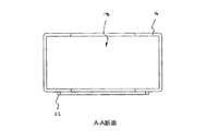
コンテナ組立体1は更に、複数(この実施形態では4つ)の取り付け点18を備え、各取り付け点は、ベース部の角部の各々にまたはその近傍に配置される。図1のコンテナ1の取り付け点18の詳細図が、図4に示されている。一形態では、取り付け点18は、通孔を含むメス型取り付け部であり、足場の対応する部分(ここでは直立部または支柱)がその通孔のなかにぴったりと入る。メス型取り付け部は更に、凹形状部の下側の縁部の下でその周囲に延びるカラー22を備える。可能な代替的形態の1つでは、凹形状部の内側は、面取りされた下側縁部を更に備えることができ、この面取りされた下側縁部は、凹形状部へ対応するオス部をガイドするのを助ける。凹形状部は、通孔または有底孔であり得る。通孔の場合には、足場のオス型部は、ベース部に肩部を備えたシャフトであり、肩部は、カラー22に当接してシャフトが凹形状部内に更に摺動して入るのを防止するように適合されている。有底孔の場合には、オス型部は、有底孔の閉鎖端に当接するように適合された端部を有するシャフトを含み得る。可能な代替形態の1つでは、シャフトはベース部から先端または先端の近傍まで先細にされ、これが凹形状部内にシャフトを配置するのを助ける。或いは、凹形状部及びシャフトを、両方ともに形状が一致する先細にし、それによって形状が一致したシャフトが凹形状部に更に摺動して入るのを防止することができる。
The container assembly 1 further comprises a plurality (four in this embodiment) of attachment points 18, each attachment point being located at or near each corner of the base portion. A detailed view of the
代替的に、フレーム1Aの取り付け点は、オス型取り付け部(図示せず)であり、これは足場の対応する開口または凹形状部内にぴったりと入るように作られた部分を有する。オス型取り付け部は、上述のタイプのものであってよく、これには、通孔型の場合には、ベース部に肩部を備えたシャフトであって、肩部がカラー22に当接してシャフトが凹形状部内に更に摺動して入るのを防止するように適合されたものが含まれ得る。有底孔型の場合、オス型部は、有底孔の閉鎖端に当接するように適合された端部を有するシャフトを含み得る。可能な形態の1つでは、シャフトはベース部から先端または先端の近傍まで先細にされ、これが凹形状部内にシャフトを配置するのを助ける。或いは、凹形状部及びシャフトを、両方ともに形状が一致する先細にし、それによって形状が一致したシャフトが凹形状部に更に摺動して入るのを防止することになる。足場の対応する開口または凹形状部は、上述のメス型取り付け部と実質的に均等な構成材のものであり得る。
Alternatively, the attachment point of the
使用に際して、コンテナ1は、大きい建物の建設現場の周辺でフレームワーク要素を動かすための安全で効果的な手段を提供する。コンテナ1には、地上で、または足場構造が設けられる位置すなわち離れた位置で積み込むことができる。コンテナ1が動かされているときの安全性を向上させるために、フレームワーク要素は、ラチェットメカニズムを備えたリールを含む保持手段8を介して固定することができ、この場合、ストラップを荷物の上に延びるようにし、U字形バー6に固定し、その後ストラップを締めて、荷物が固定することができる。これにより、コンテナ1が動かされるときに荷物がコンテナ1からの荷物の位置ずれ、落下の防止を助けることになる。コンテナ1は、1個のコンテナとして、または連結されたコンテナ列として、連結手段のけん引バー9を介してけん引することにより、フレームワーク要素が必要な領域に動かすことができる。コンテナ1は、チャネル2を介してフォークリフトにより、または持ち上げ点5及び7を介してクレーンにより持ち上げることができる。これらの方法のいずれかで、コンテナ1を、作業現場の高さ、支持足場構造の上までも持ち上げることができる。
In use, the container 1 provides a safe and effective means for moving framework elements around the construction site of a large building. The container 1 can be loaded on the ground or at a position where the scaffolding structure is provided, i.e. at a remote position. In order to improve the safety when the container 1 is moved, the framework element can be fixed via a holding means 8 comprising a reel with a ratchet mechanism, in which case the strap is placed on the luggage The bag can be fixed to the U-shaped bar 6 and then the strap can be tightened to fix the load. Thereby, when the container 1 is moved, the load helps to prevent the position shift and fall of the load from the container 1. The container 1 can be moved to the area where the framework elements are required by towing it as a single container or as a connected container row via the towing
支持足場構造は、平面的な形態で実質的に矩形であり、角部の各々またはその近傍に直立部を有する。取り付け点18を介して支持足場構造の上に配置されると、コンテナ1は、所定位置に固定され、横方向のずれやひっくり返ることが防止される。次いで保持手段8をU字形バー6から外すことが可能となり、フレームワーク要素は、作業者らが作業現場で安全に取り出すことができる。取り出しのときには、コンテナ1は、チャネル2を介してフォークリフトで持ち上げるか、または持ち上げ点5及び7を介してクレーンで持ち上げて、再度の積み込みのために下側の位置または地上まで戻すことができる。
The support scaffold structure is substantially rectangular in a planar configuration and has upstanding portions at or near each corner. When placed on the support scaffold structure via the
コンテナ1が、フレームワーク要素を、大型建築物の建設現場上の地上、より低い位置、または離れた位置から支持足場構造の上の作業現場に輸送し、その後作業者がフレームワーク要素に容易にアクセスできるようにするための安全で効果的な手段を提供することは、上述の記載内容から明らかであろう。 The container 1 transports the framework elements from the ground, lower or remote location on the construction site of the large building to the work site on the support scaffold structure, after which the operator can easily access the framework elements. It will be apparent from the foregoing description that it provides a safe and effective means for providing access.
ここで図5〜図7を参照すると、本発明の別の実施形態によるコンテナ組立体100が示されている。コンテナ組立体100の部品で、図1〜図4のコンテナ組立体1に示す対応する部品と同一(または概ね同一)なものは、同一の参照符合を節、再度詳細な説明はしない。
Referring now to FIGS. 5-7, a
コンテナ1は、足場(または同様の)構造内にフレーム1Aを配置するために複数の取り付け点を更に備える。フレーム1Aは、地上レベルまたは上側レベルのいずれかにおいて足場構造内に配置できるように構成される。
The container 1 further comprises a plurality of attachment points for placing the
コンテナ100は、フレーム横部材4及びフレーム端部材16の上にそれぞれが設置される側壁113及び端部壁117を更に有する。側壁113及び端部壁117は、コンテナ1が動かされているとき足場フレーム部材を保持する目的を果たす。図6に示す側壁113は、溶接鋼管のフレームワーク114から作製され、インフィルパネル115も含む。この実施形態では、インフィルパネル115はワイヤメッシュを含むが、他の実施形態では、限定しないが、鋼板または成型プラスチックも含むことができる。側壁113は更にフレームワーク114の上に切り欠き部116を設けて、使用に際して、コンテナ1のベース部上に配置された足場要素類への作業者のアクセスを向上させることができる。更に、足場フレームワークが構築されたとき、足場構造のクロス部材は、隣接する足場フレームワークに結合するために、これらの切り欠き部116を通すことができる。
The
図7に示すように端部壁117は、同様に溶接鋼管のフレームワーク118から作製され、インフィルパネル119も含む。この実施形態では、インフィルパネル119は鋼板を含むが、他の実施形態では、限定しないが、ワイヤメッシュまたは成型プラスチックも含むことができる。端部壁117は、上側ヒンジ結合パネル120も含み、図7にはその閉位置が、図6には部分的に開かれた位置が示されている。その閉位置では、上側ヒンジ付きパネル120は、フレームワーク114の側壁上に配置された保持ピン121によって閉状態に保持される。上側ヒンジ付きパネル120は開いてその開放位置になり、コンテナ100のベース部上に配置された足場要素類への作業者のアクセスを向上させることができる。更に、足場フレームワークが構築されたとき、足場構造のクロス部材は、隣接する足場フレームワークに結合するために、その開かれた部分を通すことができる。
As shown in FIG. 7, the
ここで、図7を参照すると、コンテナ100が持ち上げ点を通して配置された持ち上げストリップを用いてクレーンによって持ち上げられているときに使用される着脱可能なクロスブレース部材123が示されている。クロスブレース部材123は、側壁113の上部の間の所定位置に配置されて、コンテナ100が持ち上げられたとき側壁113が倒れることを防止し、持ち上げストラップが側壁113に力を加える。
Referring now to FIG. 7, there is shown a detachable
図5〜図7を参照すると、1以上のコンテナ100を積み重ねることを可能にする目的で、側壁113の各々の上に配置された支持フランジ124が示されている。支持フランジ124は、その水平要素が、上に積み重ねられたコンテナ100を支持し、フォークリフトチャネルがその上に載るように構成される。垂直要素は、2つのフォークリフトチャネルの間で、コンテナ100のフレーム横部材4の内部に積み重ねられたコンテナ100を位置付け、積み重ねられたコンテナ100の長さ方向及び横方向の動きが生ずるのを防止する。
Referring to FIGS. 5-7, a
使用に際しては、コンテナ100は、大きい建物の建設現場の周辺でフレームワーク要素を動かすための安全で効果的な手段を提供する。コンテナ100には、地上で、または足場構造が設けられる位置すなわち離れた位置でフレームワーク要素を積み込むことができる。側壁113及び端部壁117は、コンテナ100が動かされるときに荷物がコンテナ100からの荷物の位置ずれ、落下の防止を助けることになる。コンテナ100は、1個のコンテナ100として、または連結されたコンテナ100のコンテナ列として、連結手段のけん引バー9を介してけん引することにより、フレームワーク要素が必要な領域に動かすことができる。コンテナ100は、チャネルを介してフォークリフトにより、または持ち上げ点を介してクレーンにより持ち上げることができる。クレーンによる持ち上げの場合、クロスブレース部材123が、2つの側壁113の間にそれが倒れるのを防止するべく配置される。これらの方法のいずれかで、コンテナ100を、作業現場の高さ、支持足場構造の上までも持ち上げることができる。
In use, the
ここで図8〜図10を参照すると、PCT/AU2013/000855(国際公開第2014/019029号(特許文献1))に記載されたタイプの支柱または足場組立体200であって、平面的な形態で実質的に矩形であり、その各角部またはその近傍に直立部または支柱202を有するものが図示されている。
Referring now to FIGS. 8-10, there is shown a planar or
コンテナ組立体100(またはコンテナ組立体1)は、図8に示すように地上に配置(または保管)され、足場組立体200の各直立部202の下端部204は、コンテナ組立体100の上から取り付け点112を通して受容され、コンテナ組立体100もその上に支持される床面または地面に延びている。ここで図9を参照すると、第2の及び後続の足場組立体200は、最下部の足場組立体200の上に積み重ねることができる。このようにして、コンテナ組立体100は、足場組立体200を支持することなく足場組立体200のフットプリント内に保管することができる。
The container assembly 100 (or the container assembly 1) is placed (or stored) on the ground as shown in FIG. 8, and the
ここで図10を参照すると、足場組立体200の各直立部202の上側端206は、コンテナ組立体100の下から取り付け点112によって受容されている。
Referring now to FIG. 10, the
取り付け点112を介して支持する足場組立体200の上に配置されると、コンテナ100は、所定位置に固定され、横方向のずれやひっくり返ることが防止される。次いでクロスブレース部材123をから取り外すことが可能となり、上側ヒンジ付きパネル120をロック解除して折り畳み、アクセスを向上させることができる。荷物を取り出されたとき、コンテナ100は、所定位置に保持されて足場構造の一部を形成するか、合板で覆われてプラットフォームを形成するか、またはチャネルを介してフォークリフトによって持ち上げられるか、または持ち上げ点を介してクレーンによって持ち上げて、再度の積み込みのために下側の位置または地上まで戻すことができる。
When placed on a
コンテナ100が、フレームワーク要素を、大型建築物の建設現場上の地上、より低い位置、または離れた位置から支持足場構造の上の作業現場に輸送し、その後作業者がフレームワーク要素に容易にアクセスできるようにするための安全で効果的な手段を提供することは、上述の記載内容から明らかであろう。
The
本明細書及び特許請求の範囲の全体において、文脈上別の解釈が必要とならない限り、用語「含む/有する」、「備える」及びその活用形は、記載された整数または整数の群の個数を有することを暗示しているが、他の整数または整数の群の場合を排除するものではないことを理解されたい。 Throughout this specification and claims, the terms “include / have”, “comprise” and their conjugations refer to the number of integers or groups of integers described, unless the context requires otherwise. It is to be understood that this is implied but does not exclude the case of other integers or groups of integers.
本明細書中に記載されたあらゆる従来技術に対する参照は、そのような従来技術が技術常識の一部を形成することの示唆を認めるものとして解釈されないものか、またはそのようなものとして解釈されるべきではない。 References to any prior art described herein are not to be construed as an admission that such prior art forms part of the common general knowledge, or are interpreted as such. Should not.
本発明が、上述の特定の用途における使用に限定されないことは当業者には理解されよう。本発明は、本明細書に記載された特定の要素及び/または特徴に関するその好ましい実施形態に制限されるものではない。本発明は、ここに開示した実施形態に限定されず、特許請求の範囲の請求項によって特定される発明の精神を逸脱することなく、多種の再構成、改変、及び代替的形態を含めて実施可能であることは理解されよう。 Those skilled in the art will appreciate that the present invention is not limited to use in the specific applications described above. The present invention is not limited to its preferred embodiments relating to the specific elements and / or features described herein. The invention is not limited to the embodiments disclosed herein, but may be practiced including various reconfigurations, modifications, and alternative forms without departing from the spirit of the invention as defined by the claims. It will be understood that this is possible.
Claims (11)
平らな板状の形態で、4つの角部を有する実質的に矩形であるベース部と、
前記ベース部の下から下がる複数の車輪であって、前記複数の車輪によって前記コンテナが回動可能となるように構成され、前記コンテナは、前記車輪を介して床面または地面から支持される、該複数の車輪と、
前記角部の各々または前記角部の各々の近傍に取り付け点とを含み、
各取り付け点は、通孔を含み、前記通孔は、それぞれの前記足場組立体用の直立部部品の下端を受容して通過させ、前記足場組立体上への荷重が前記コンテナによって支持されなくなるように、前記足場組立体用の直立部部品を前記コンテナの上から前記ベース部を通して前記床面または地面に達するまで延びた状態とさせられるように適合されていることを特徴とするコンテナ。 A container for parts for a scaffold assembly,
A substantially rectangular base with four corners in the form of a flat plate,
A plurality of wheels descending from below the base part, the container being configured to be rotatable by the plurality of wheels, the container being supported from the floor or the ground via the wheels, The plurality of wheels;
And a mounting point in the vicinity of each of each or the corner of the angle section,
Each attachment point includes a through hole that receives and passes a lower end of an upright part for the respective scaffold assembly so that a load on the scaffold assembly is not supported by the container. The container is adapted to allow the upright part for the scaffold assembly to extend from the top of the container through the base until it reaches the floor or the ground .
ベース部を含み、前記ベース部が一対のフォークリフトタインを受容するように適合されていることを特徴とするコンテナ。 The container according to claim 1 or 2 ,
A container including a base portion, wherein the base portion is adapted to receive a pair of forklift tines.
少なくとも1つの持ち上げ点を更に含み、前記持ち上げ点を介して前記コンテナがクレーンで持ち上げ可能であることを特徴とするコンテナ。 The container according to any one of claims 1 to 3 ,
A container further comprising at least one lifting point through which the container can be lifted by a crane.
前記ベース部に対して前記足場組立体用の各直立部部品を固定するための手段とを更に含むことを特徴とするコンテナ。 The container according to any one of claims 1 to 4 ,
Container, characterized in that to the front SL base unit further comprises a means for fixing the upright part for the scaffold assembly.
前記ベース部の一対の側部に沿って取り付けられる側壁と、
前記ベース部の一対の端部に沿って取り付けられる端部壁とを更に含むことを特徴とするコンテナ。 The container according to any one of claims 1 to 4 ,
Side walls mounted along the pair of side portions of the front SL base portion,
The container further comprising an end wall attached along a pair of ends of the base portion.
クロスブレースを更に含み、
前記クロスブレースは、前記側壁に着脱自在に架け渡されるように適合されることを特徴とするコンテナ。 The container according to claim 6 ,
Further including a cross brace,
The container, wherein the cross brace is adapted to be detachably mounted on the side wall.
前記側壁が、前記ベース部へのアクセスを提供するため、及び前記足場組立体の長手方向に垂直な水平方向に延びる横方向部材を受容するための切り欠き部を含むことを特徴とするコンテナ。 A container according to claim 6 or 7 ,
Said side wall, to provide access to said base portion, and a container which comprises a cutout portion for receiving a transverse member extending in the vertical horizontal direction in the longitudinal direction of the scaffolding assembly.
前記端部壁が、ヒンジ付き上部を含むことを特徴とするコンテナ。 The container according to claim 6 ,
A container wherein the end wall includes a hinged top.
複数の前記コンテナが、足場組立体の組み立てに使用されていないときに積み重ねることが可能となるように、前記コンテナを少なくとも1つの他のコンテナに積み重ねるための手段を更に含むことを特徴とするコンテナ。 A container according to any one of claims 1 to 9 ,
Container further comprising means for stacking said container on at least one other container such that a plurality of said containers can be stacked when not being used to assemble a scaffold assembly .
平らな板状の形態で、4つの角部を有する実質的に矩形であるベース部と、
前記ベース部の下から下がる複数の車輪であって、前記複数の車輪によって前記コンテナが回動可能となるように構成され、前記コンテナは、前記車輪を介して床面または地面から支持される、該複数の車輪と、
前記角部の各々または前記角部の各々の近傍に取り付け点とを含み、
各取り付け点は、通孔を含み、前記通孔は、それぞれの前記型枠支持システム用の直立部部品の下端を受容して通過させ、前記型枠支持システム上への荷重が前記コンテナによって支持されなくなるように、前記型枠支持システム用の直立部部品を前記コンテナの上から前記ベース部を通して前記床面または地面に達するまで延びた状態とさせられるように適合されていることを特徴とするコンテナ。 A container for parts for a formwork support system,
A substantially rectangular base with four corners in the form of a flat plate,
A plurality of wheels descending from below the base portion, the container being configured to be rotatable by the plurality of wheels, the container being supported from the floor or the ground via the wheels, The plurality of wheels;
And a mounting point in the vicinity of each of each or the corner of the angle section,
Each attachment point includes a through hole that receives and passes a lower end of an upright part for the respective formwork support system so that a load on the formwork support system is supported by the container. The upright part for the formwork support system is adapted to extend from the top of the container through the base until it reaches the floor or ground, container.
Applications Claiming Priority (3)
| Application Number | Priority Date | Filing Date | Title |
|---|---|---|---|
| AU2014900722A AU2014900722A0 (en) | 2014-03-04 | A stillage for framework elements | |
| AU2014900722 | 2014-03-04 | ||
| PCT/AU2015/000116 WO2015131228A1 (en) | 2014-03-04 | 2015-03-03 | A container for framework elements |
Publications (2)
| Publication Number | Publication Date |
|---|---|
| JP2017512270A JP2017512270A (en) | 2017-05-18 |
| JP6592449B2 true JP6592449B2 (en) | 2019-10-16 |
Family
ID=54054258
Family Applications (1)
| Application Number | Title | Priority Date | Filing Date |
|---|---|---|---|
| JP2016555663A Expired - Fee Related JP6592449B2 (en) | 2014-03-04 | 2015-03-03 | Container for framework elements |
Country Status (11)
| Country | Link |
|---|---|
| US (1) | US20170073984A1 (en) |
| EP (1) | EP3114291B1 (en) |
| JP (1) | JP6592449B2 (en) |
| KR (1) | KR102354929B1 (en) |
| CN (1) | CN106103863A (en) |
| AU (1) | AU2015226825B2 (en) |
| CA (1) | CA2940049A1 (en) |
| NZ (1) | NZ724850A (en) |
| RU (1) | RU2016137821A (en) |
| SG (1) | SG11201607062UA (en) |
| WO (1) | WO2015131228A1 (en) |
Families Citing this family (8)
| Publication number | Priority date | Publication date | Assignee | Title |
|---|---|---|---|---|
| AU2017202444B2 (en) * | 2016-12-19 | 2019-06-20 | Voideck Ipco Limited | A void platform and a method for providing a platform support across a building void |
| CN108791698A (en) * | 2018-06-14 | 2018-11-13 | 芜湖恒安钢结构有限公司 | A kind of shipbuilding scaffold carrying platform |
| JP7311134B2 (en) * | 2018-06-20 | 2023-07-19 | ジー・オー・ピー株式会社 | Platform bridge, platform system and transport method |
| DE102018222099A1 (en) * | 2018-12-18 | 2020-06-18 | Hünnebeck GmbH | Method and device for the construction of buildings |
| JP7360139B2 (en) * | 2019-03-05 | 2023-10-12 | ジー・オー・ピー株式会社 | Workbench system storage method, transportation method, and workbench system |
| CN110820564B (en) * | 2019-10-15 | 2021-03-26 | 同济大学 | Liftable and openable bent cap construction overhaul multipurpose platform |
| CN111058608A (en) * | 2019-12-20 | 2020-04-24 | 北京施图美达装饰工程有限公司 | A light-duty scaffold frame for interior decoration's dismouting of being convenient for |
| CN114215323B (en) * | 2021-12-27 | 2023-04-07 | 广州地铁设计研究院股份有限公司 | Civil engineering and mechanical integration assembly type maintenance platform and construction method thereof |
Family Cites Families (38)
| Publication number | Priority date | Publication date | Assignee | Title |
|---|---|---|---|---|
| US859092A (en) * | 1906-01-16 | 1907-07-02 | Walter W Massie | Spark-gap apparatus. |
| US2988313A (en) * | 1959-09-16 | 1961-06-13 | Paltier Corp | Anchor for pallet frame |
| US3684285A (en) * | 1970-06-19 | 1972-08-15 | John Robert Kane | Chess game apparatus |
| US3857494A (en) * | 1973-07-16 | 1974-12-31 | Rockwell International Corp | Modular rack assembly |
| US3873114A (en) * | 1973-12-14 | 1975-03-25 | Rilma L Brown | Portable container apparatus |
| US4027599A (en) * | 1975-10-22 | 1977-06-07 | Sapp Lawrence G | Unitizing frame for a pallet |
| DE2836379C3 (en) * | 1978-08-19 | 1981-11-26 | Langer, geb. Layher, Ruth, 7129 Güglingen | palette |
| US4430839A (en) * | 1981-01-23 | 1984-02-14 | W. R. Carpenter And Co. Ltd. | Scaffold frame |
| DE3102468C2 (en) * | 1981-01-26 | 1984-04-12 | Johann B. 6530 Bingen Pfeifer | Mobile assembly frame with continuously adjustable lifting platform |
| JPS5926357A (en) * | 1982-08-02 | 1984-02-10 | 新明和工業株式会社 | Cart |
| US4673092A (en) * | 1985-09-30 | 1987-06-16 | Lockwood Manufacturing Company | Multi-level rack assembly |
| US4901650A (en) * | 1988-04-08 | 1990-02-20 | Armstead Richard L | Industrial pallet having upward extending support posts and locking means |
| CN2150277Y (en) * | 1992-12-30 | 1993-12-22 | 安玉明 | Moveable scaffold |
| JP2802224B2 (en) * | 1994-03-30 | 1998-09-24 | 鹿島建設株式会社 | Containers for carrying construction materials and equipment |
| USD363841S (en) * | 1994-11-14 | 1995-11-07 | BBA Holdings, Inc. | Shelving assembly |
| GB9506095D0 (en) * | 1995-03-24 | 1995-05-10 | Kitchen John E M | Movable platform |
| DE29505366U1 (en) * | 1995-03-30 | 1995-05-24 | Mueller & Baum | Transport frame for scaffolding parts |
| JPH08318858A (en) * | 1995-05-29 | 1996-12-03 | Daifuku Co Ltd | Conveying apparatus for fluid container |
| US6065407A (en) * | 1998-07-27 | 2000-05-23 | Alltrend Co., Ltd. | Locking sleeve assembly for a display shelf |
| CN2389963Y (en) * | 1999-07-08 | 2000-08-02 | 冯印亭 | Multipurpose quick-mounting scaffold |
| US6357611B1 (en) * | 2000-03-31 | 2002-03-19 | Protend Co., Ltd | Sectional rack |
| US20010045718A1 (en) * | 2000-05-18 | 2001-11-29 | Boirum Ron P. | Multiple function job site work cart |
| US6364139B1 (en) * | 2000-10-31 | 2002-04-02 | Pro Trend Co., Ltd. | Two-part shelf-holder for sectional rack |
| US20040000458A1 (en) * | 2002-06-28 | 2004-01-01 | Weiss Paul E. | Baggage cart suitcase |
| US6820878B2 (en) * | 2002-08-16 | 2004-11-23 | Hamid Safari | Medical device transportation unit |
| US7114733B2 (en) * | 2004-08-26 | 2006-10-03 | Ira Downs | Mobile work and supply station with crane eyelets and blueprint desk |
| CN100467354C (en) * | 2005-06-10 | 2009-03-11 | 中国国际海运集装箱(集团)股份有限公司 | Tray box |
| US8590921B2 (en) * | 2006-05-12 | 2013-11-26 | Dulond Tool & Engineering, Inc. | Band cart storage system and method |
| KR200432482Y1 (en) * | 2006-09-20 | 2006-12-04 | 홍성철 | The assembly scaffolding |
| US7878338B2 (en) * | 2006-11-07 | 2011-02-01 | Maxson Don F | Transport and storage container for scaffold frames and braces |
| WO2010022044A2 (en) * | 2008-08-18 | 2010-02-25 | University Of Maine System Board Of Trustees | Blast and ballistic protection system |
| US8602443B2 (en) * | 2010-01-19 | 2013-12-10 | Todd E. A. Moore | Adjustable multi-purpose dolly |
| US8342544B1 (en) * | 2011-03-15 | 2013-01-01 | Patrick Blewett | Utility cart |
| WO2013191700A1 (en) * | 2012-06-21 | 2013-12-27 | Beauchamp Brenda Jo | Shopping cart with folding legs |
| EP2880228B1 (en) * | 2012-08-02 | 2020-07-08 | Form 700 Pty Ltd | Scaffold structure |
| US9221484B2 (en) * | 2013-04-03 | 2015-12-29 | Eric W. Logvin | Configurable cart |
| CN103321396A (en) * | 2013-05-30 | 2013-09-25 | 河南省电力公司信阳供电公司 | Folding type scaffold special for electric power sectors |
| CN204152176U (en) * | 2014-09-30 | 2015-02-11 | 潘增权 | Assembly type large span Mobile operating platform |
-
2015
- 2015-03-03 NZ NZ724850A patent/NZ724850A/en unknown
- 2015-03-03 JP JP2016555663A patent/JP6592449B2/en not_active Expired - Fee Related
- 2015-03-03 SG SG11201607062UA patent/SG11201607062UA/en unknown
- 2015-03-03 RU RU2016137821A patent/RU2016137821A/en unknown
- 2015-03-03 WO PCT/AU2015/000116 patent/WO2015131228A1/en active Application Filing
- 2015-03-03 CA CA2940049A patent/CA2940049A1/en not_active Abandoned
- 2015-03-03 US US15/123,393 patent/US20170073984A1/en not_active Abandoned
- 2015-03-03 AU AU2015226825A patent/AU2015226825B2/en active Active
- 2015-03-03 KR KR1020167026916A patent/KR102354929B1/en active IP Right Grant
- 2015-03-03 EP EP15758737.9A patent/EP3114291B1/en active Active
- 2015-03-03 CN CN201580011881.XA patent/CN106103863A/en active Pending
Also Published As
| Publication number | Publication date |
|---|---|
| EP3114291B1 (en) | 2022-10-19 |
| RU2016137821A (en) | 2018-04-04 |
| CA2940049A1 (en) | 2015-09-11 |
| AU2015226825A1 (en) | 2016-10-13 |
| JP2017512270A (en) | 2017-05-18 |
| NZ724850A (en) | 2022-01-28 |
| WO2015131228A1 (en) | 2015-09-11 |
| KR20160127802A (en) | 2016-11-04 |
| SG11201607062UA (en) | 2016-09-29 |
| EP3114291A1 (en) | 2017-01-11 |
| CN106103863A (en) | 2016-11-09 |
| KR102354929B1 (en) | 2022-01-24 |
| RU2016137821A3 (en) | 2018-07-10 |
| AU2015226825B2 (en) | 2018-07-26 |
| EP3114291A4 (en) | 2017-07-26 |
| US20170073984A1 (en) | 2017-03-16 |
Similar Documents
| Publication | Publication Date | Title |
|---|---|---|
| JP6592449B2 (en) | Container for framework elements | |
| DK3065595T3 (en) | Roll-out storage system for containers, method of storing cargo | |
| US7878338B2 (en) | Transport and storage container for scaffold frames and braces | |
| US9506267B2 (en) | Method for supporting an upstanding mast | |
| US10377405B2 (en) | Scaffold storage and transportation dolly set | |
| US20090241809A1 (en) | Materials safety cage and associated methods | |
| US4901650A (en) | Industrial pallet having upward extending support posts and locking means | |
| JP2007131332A (en) | Tank container | |
| US20170129520A1 (en) | Scaffolding transport cart | |
| CN101878160B (en) | Transport arrangement | |
| AU2016102095A4 (en) | Modular gantry structure | |
| JPH07112807A (en) | Rack construction method and jig for automatic store | |
| EP2927179B1 (en) | Outrigger pad carrier | |
| GB1565498A (en) | Portable buildings | |
| FI129374B (en) | Transport frame for construction site fencing, system and method for transporting and erecting construction site fencing by using transport frames | |
| KR20090080898A (en) | Frame for lifting up construction member using truss | |
| KR101295461B1 (en) | Folding safety footrest for temporary bent work | |
| GB1580894A (en) | Collapsible container | |
| AU2016277682A1 (en) | Transport Device | |
| JP6751315B2 (en) | Transportation platform with scaffolding | |
| JP2004218245A (en) | Support for main rope | |
| NZ727329B2 (en) | Modular gantry structure | |
| AU4739099A (en) | A transportation platform and components thereof | |
| GB1565500A (en) | Portable buildings |
Legal Events
| Date | Code | Title | Description |
|---|---|---|---|
| A621 | Written request for application examination |
Free format text: JAPANESE INTERMEDIATE CODE: A621 Effective date: 20180227 |
|
| A977 | Report on retrieval |
Free format text: JAPANESE INTERMEDIATE CODE: A971007 Effective date: 20181225 |
|
| A131 | Notification of reasons for refusal |
Free format text: JAPANESE INTERMEDIATE CODE: A131 Effective date: 20190108 |
|
| A521 | Request for written amendment filed |
Free format text: JAPANESE INTERMEDIATE CODE: A523 Effective date: 20190325 |
|
| TRDD | Decision of grant or rejection written | ||
| A01 | Written decision to grant a patent or to grant a registration (utility model) |
Free format text: JAPANESE INTERMEDIATE CODE: A01 Effective date: 20190827 |
|
| A61 | First payment of annual fees (during grant procedure) |
Free format text: JAPANESE INTERMEDIATE CODE: A61 Effective date: 20190920 |
|
| R150 | Certificate of patent or registration of utility model |
Ref document number: 6592449 Country of ref document: JP Free format text: JAPANESE INTERMEDIATE CODE: R150 |
|
| LAPS | Cancellation because of no payment of annual fees |