JP6592376B2 - Elevator and rescue operation method - Google Patents
Elevator and rescue operation method Download PDFInfo
- Publication number
- JP6592376B2 JP6592376B2 JP2016035025A JP2016035025A JP6592376B2 JP 6592376 B2 JP6592376 B2 JP 6592376B2 JP 2016035025 A JP2016035025 A JP 2016035025A JP 2016035025 A JP2016035025 A JP 2016035025A JP 6592376 B2 JP6592376 B2 JP 6592376B2
- Authority
- JP
- Japan
- Prior art keywords
- car
- brake
- controller
- solenoid coil
- braking force
- Prior art date
- Legal status (The legal status is an assumption and is not a legal conclusion. Google has not performed a legal analysis and makes no representation as to the accuracy of the status listed.)
- Active
Links
Images


Classifications
-
- B—PERFORMING OPERATIONS; TRANSPORTING
- B66—HOISTING; LIFTING; HAULING
- B66B—ELEVATORS; ESCALATORS OR MOVING WALKWAYS
- B66B5/00—Applications of checking, fault-correcting, or safety devices in elevators
- B66B5/02—Applications of checking, fault-correcting, or safety devices in elevators responsive to abnormal operating conditions
Description
本発明はエレベーターに関する。 The present invention relates to an elevator.
従来のエレベーターは、電力変換器から電動機を回転させ、電動機と連結しているシーブを介して、ロープを上下方向へ移動させることで、ロープと接続されているかごの昇降を可能としている。この電力変換器や電動機、電動機と接続したエンコーダ等、駆動システムの一部が故障した場合、エレベーターは停止する。エレベーターのかごの停止した位置が階と階の間であり、この時に乗客がかご内にいると閉じ込めが発生する。閉じ込めた状態ではかごは動かないため、乗客の安全性は担保されるが、乗客は不快感を受けることになる。 In a conventional elevator, an electric motor is rotated from a power converter, and a rope connected to the electric motor is moved up and down through a sheave connected to the electric motor, so that a car connected to the rope can be moved up and down. When a part of the drive system such as the power converter, the electric motor, or the encoder connected to the electric motor breaks down, the elevator stops. The position where the elevator car stops is between the floors, and confinement occurs when passengers are in the car at this time. Since the car does not move in the confined state, the safety of the passenger is ensured, but the passenger is uncomfortable.
このような駆動システムの故障により閉じ込められた乗客を救出するための方法としては、一般的には保守作業員により行われる。特に、かご内の重量がつり合い重りとつり合っていない場合には、ブレーキを手動で開放することにより、かごとつり合い重りとのアンバランスを利用して、最寄階までかごを移動させることで乗客を救出する。 As a method for rescuing a passenger who is trapped due to a failure of such a drive system, a maintenance worker generally performs the method. In particular, when the weight in the car is not balanced with the counterweight, the car can be moved to the nearest floor using the unbalance between the car and the counterweight by manually releasing the brake. Rescue passengers.
一方で、上記の方法は保守作業員の到着を待ってから行われるため、乗客の救出に待ち時間が発生する。これを解決する方法として、特許文献1にブレーキの開放を自動で行う専用の端末を利用することで、早期に救出する方法が開示されている。
On the other hand, since the above method is performed after waiting for the maintenance worker to arrive, a waiting time is required for rescue of passengers. As a method for solving this problem,
特許文献1では、かごの移動を検知するまで始動時の電圧を線形に上昇させることが示されているが、ブレーキに使用されるコイルの応答性が低い場合、ブレーキが開き始めてかごが移動するときには、電圧指令がブレーキを十分に開くことのできる値に達してしまうため、かごの急激な増速を発生させてしまう可能性がある。
In
上記課題を解決するため、本発明は、乗りかごと、一端が乗りかごに接続されるロープと、ロープの他端に接続されるつり合い錘と、ロープが巻き掛けられたシーブと、給電される電流が増加することで制動力を弱めるソレノイドコイルを有し、シーブに制動力を加えることで乗りかごの移動を制動するブレーキ装置と、ソレノイドコイルへ電流を給電するブレーキ電源と、乗りかごの移動速度を検出する移動速度検出手段と、移動速度検出手段に応じてブレーキ電源が給電する電流を制御するコントローラと、を備え、コントローラは、乗りかごが停止している場合、所定の時間が経過する毎にソレノイドコイルに給電する電流を所定値分ずつ階段状に増加させる指令をブレーキ電源へ送信し、移動速度検出手段によって乗りかごの速度変化が検出された場合、ソレノイドコイルに給電する電流の増加を停止する指令をブレーキ電源へ送信することで、ブレーキ装置による制動力を発生させながら、乗りかごとつり合い錘との重量のアンバランスによって乗りかごを移動させることを特徴とするエレベーターを提供する。
また、上記課題を解決するため、本発明は、乗りかごと、一端が乗りかごに接続されるロープと、ロープの他端に接続されるつり合い錘と、ロープが巻き掛けられたシーブと、給電される電流が増加することで制動力を弱めるソレノイドコイルを有し、シーブに制動力を加えることで乗りかごの移動を制動するブレーキ装置と、ソレノイドコイルへ電流を給電するブレーキ電源と、乗りかごの移動速度を検出する移動速度検出手段と、移動速度検出手段に応じてブレーキ電源が給電する電流を制御するコントローラと、を備え、コントローラは、乗りかごが停止している場合、所定の時間が経過する毎にソレノイドコイルに給電する電流を所定値分ずつ増加させる指令をブレーキ電源へ送信し、移動速度検出手段によって乗りかごの速度変化が検出された場合、ソレノイドコイルに給電する電流の増加を停止する指令をブレーキ電源へ送信することで、ブレーキ装置による制動力を発生させながら、乗りかごとつり合い錘との重量のアンバランスによって乗りかごを移動させ、コントローラは、乗りかごが移動している場合、かつ、移動速度検出手段によって乗りかごの速度が規定速度を超えたことが検出された場合、ソレノイドコイルに給電される電流を時間に対して連続的に減少させる指令をブレーキ電源へ送信し、乗りかごを停止させることを特徴とするエレベーターを提供する。
In order to solve the above problems, the present invention supplies power to a car, a rope having one end connected to the car, a counterweight connected to the other end of the rope, and a sheave around which the rope is wound. A brake device that has a solenoid coil that weakens the braking force by increasing the current, brakes the movement of the car by applying a braking force to the sheave, a brake power supply that supplies current to the solenoid coil, and the movement of the car A moving speed detecting means for detecting a speed, and a controller for controlling a current supplied by the brake power supply in accordance with the moving speed detecting means, and the controller passes a predetermined time when the car is stopped. a command to increase stepwise the current to power the solenoid coil by a predetermined value minutes transmitted to the brake power for each speed of the elevator car by the moving speed detecting means strange Is detected, a command to stop increasing the current supplied to the solenoid coil is sent to the brake power supply, so that the braking force generated by the brake device is generated and the vehicle is driven by the unbalance of the weight of the carriage and the counterweight. An elevator characterized by moving a car is provided.
In order to solve the above problems, the present invention provides a car, a rope having one end connected to the car, a counterweight connected to the other end of the rope, a sheave around which the rope is wound, and power feeding. Having a solenoid coil that weakens the braking force by increasing the generated current, braking the movement of the car by applying a braking force to the sheave, a brake power supply for supplying current to the solenoid coil, and the car A moving speed detecting means for detecting the moving speed of the vehicle, and a controller for controlling the current supplied by the brake power supply in accordance with the moving speed detecting means. Each time it passes, a command to increase the current supplied to the solenoid coil by a predetermined value is sent to the brake power supply, and the speed of the car changes by the moving speed detection means If it is detected, a command to stop increasing the current supplied to the solenoid coil is sent to the brake power supply to generate a braking force by the brake device, while the car is balanced by the weight of the car and the balance weight. The controller moves the current supplied to the solenoid coil over time when the car is moving and when the moving speed detecting means detects that the car speed exceeds the specified speed. In contrast, an elevator is characterized in that a command for continuously decreasing is transmitted to a brake power source to stop a car.
ブレーキ開放運転において乗りかごの移動開始時の急激な可速を防ぐことができる。 It is possible to prevent rapid acceleration at the start of movement of the car in the brake release operation.
以下、図面を参照して、一実施の形態について詳細を説明する。 Hereinafter, an embodiment will be described in detail with reference to the drawings.
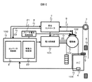
図1は、本発明におけるエレベーターシステムを示す全体構成図である。エレベーターのかご104の移動は、エレベーターコントローラ100によって制御される。エレベーターコントローラ100は、エレベーターの運行制御を行うエレベーター制御部2の他に、制動力制御部20を備えている。
FIG. 1 is an overall configuration diagram showing an elevator system according to the present invention. The movement of the
かご104は、建屋に形成された昇降路内を複数の階床間に渡って移動し、ロープを介してつり合い重りと呼ばれるかご104とバランスを取るためのおもりに接続されている。かご104には、乗り場側扉を係合して開閉する乗りかご側扉が設けられている。かご104の移動は、電動機103によって綱車が駆動されることにより行われる。電動機103には、電力変換器101によって駆動用の電力の供給が行われる。電力変換器101は、エレベーターコントローラ100のかご位置制御指令に従って電動機を制御するための電力を出力する。また、エンコーダなどのパルス発生器は電動機103に取り付けられており、エレベーターコントローラ100は電動機103の回転によって生じるパルスを計数することにより、電動機103の速度、かご104の昇降路移動方向、位置、移動距離などを計算する。エレベーターコントローラ100が乗りかごを制動させたい場合は、ブレーキ電源停止指令及び動力電源停止指令(図示せず)を出力する。これらの停止指令を受けて、ブレーキ電源はブレーキ102の作動を、動力電源は電力変換器101への電源供給のカットを行い、かご104を制動させる。ブレーキ電源及び動力電源は、コンタクタと呼ばれる電磁接触器で構成される回路である。
The
ブレーキ102は、シーブを摩擦摺動で制動させるためのブレーキパッド、ブレーキパッドを引き上げてシーブとブレーキパッドのギャップを確保するためのソレノイドコイル及び鉄芯(コア)で構成される。通常、ソレノイドコイルに電力が供給されると、電磁力によりブレーキパッドが引き上げられ、シーブはブレーキパッドによる拘束がなくなり、自由に回転できるようになる。ソレノイドコイルへの給電はブレーキ電源からのリレーを介して行われる。また、ブレーキ102は、ブレーキ電流制御回路21により、ソレノイドコイルへ流れる電流(ブレーキ電流)を制御する回路により、制動力を変化させることが可能な構成となっている。
The
ブレーキ電流制御回路21は、インバータ回路やチョッパ回路といった電流ないしは電圧を制御する変換器、ブレーキ電流を検出するホールCT、ブレーキ電流を制御するためのコントローラで構成され、エレベーターコントローラ100よりソレノイドコイルに流れる電流の指令値(ブレーキ電流指令)を受けて、その指令値にブレーキ電流を制御する。なお、本実施例では制動力を変化させるための一例として、ソレノイドコイルを用いた電流に応じた制動力を変化させるブレーキ機構を例示したが、たとえば直動式のアクチュエータを用いることによる、距離に応じて制動力を変化させるブレーキや、回転機構を用いることによる、回転角に応じて制動力を変化させるブレーキ(シューブレーキなど)でもよい。総じて、ある指令に応じてブレーキの制動力を変化させるものであれば、ブレーキの種類には依存しない。
The brake
秤センサ4はかご内の乗客の人数を検出するのに使用する。通常運転中であれば、かごとつり合い重りの重量差を補償するための必要トルクを計算するのに使用される。秤センサは、かご床面が金属である場合には、かご枠に設けられた近接センサなどでかご床面のたわみ量から重量を推定する方式が用いられる。
The
位置センサ5は、検出板6を検出することで、エレベーターが戸開可能な位置にいるかどうかを検出する、ドアゾーンセンサである。 The position sensor 5 is a door zone sensor that detects whether the elevator is at a position where the door can be opened by detecting the detection plate 6.
安全コントローラ1は、エレベーターコントローラ100とは独立してブレーキ電源及び動力電源を遮断することでかご104を制動させる、安全システムを構成するコントローラである。安全コントローラ1は、処理を実行するCPU(Central Processing Unit)を中心とした構成であり、他にCPUの異常を検出するためのウォッチドッグタイマや、電源異常を監視する回路を有する。またCPUの処理異常を検出するために、CPUを2重化することによる相互比較を行う構成を持つ場合もある。
The
安全コントローラ1の入力は、かごの位置・速度・加速度を検出するための手段7や、エレベーターの安全装置の作動を検出する手段、で構成される。かごの位置・速度・加速度を検出するための手段7は、たとえばかごの位置に応じてパルスを出力するパルス発生器であり、本実施例ではガバナにエンコーダを取り付けたものを図示している。これは、他にガイドレールに直接的にローラーを押し付けて乗りかごの移動を検出するタイプや、レールを磁化して検出するタイプなど、かごの絶対的または相対的な位置を検出できる手段であればよい。エレベーターコントローラ100から安全コントローラ1への出力8の話がない。
The input of the
安全コントローラ1の出力は、ブレーキ電源遮断出力9と動力電源遮断出力10、及び安全コントローラ1で検出されるかご位置及び速度情報出力23で構成される。ブレーキ電源遮断出力9はブレーキ電源を遮断し、ブレーキ102を作動させるための出力である。また同様に、動力電源遮断出力10は電力変換器101の電力源を遮断することで電動機103を停止させるための出力である。いずれの出力も、かごを制動するために使用される。
The output of the
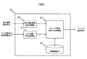
図2は制動力制御部21のブロック図であり、本図を用いて概要について説明する。救出運転開始処理部30は、エレベーターコントローラ100のエレベーター制御部2より送信される救出運転開始指令を検出する処理部であり、救出運転開始指令で識別される救出運転の開始または停止を、ブレーキ電流指令作成処理32へ送信する。かご速度検出処理部31は、安全コントローラより入力されるかご位置及び速度情報出力23を受けて、現在の昇降路内における自号機のかご速度を検出し、その検出したかご速度を出力する。ブレーキ電流指令処理部32は、救出運転開始検出処理部30から出力される救出運転開始指令により、ブレーキ電流指令の作成を行い、作成したブレーキ電流指令をブレーキ電流制御回路21へ出力する。また、ブレーキ電流指令作成処理部32は、かご速度検出処理部31より出力されるかご速度を元に、ブレーキ電流指令を変化させる。ブレーキ電流指令作成処理部32がブレーキ指令を作成する時、機種情報データベース(DB)33よりブレーキの種類によって異なる調整パラメータを入手する。この調整パラメータとは具体的には、磁束の変化を待つために一定値電流を上昇させた後一定時間電流指令値の上昇を停止させる時間が挙げられる。電流指令の変化からに対して、ブレーキトルクを変化させる磁束の変化には遅れが生じるため、それを考慮し、磁束の変化を待つために一定値電流を上昇させた後一定時間電流指令値の上昇を停止させる時間を設ける。この電流指令値の変化と磁束変化の遅れはブレーキの構造や大きさによって異なるため、機種情報データベース(DB)からこの情報を入手する。
FIG. 2 is a block diagram of the braking
図3は、ブレーキ電流指令作成処理部32が作成するブレーキ電流指令i*とソレノイドコイルに流れるブレーキ電流i、ブレーキパッドとシーブの間に働くブレーキトルクT、およびかご速度の関係を横軸時間として図示したものである。また、説明の便宜上、時間軸を(a)から(d)の4区間に分割している。以下、基本の動作方法について、区間(a)から順に説明する。
FIG. 3 shows the relationship between the brake current command i * created by the brake current command
区間(a)は、ブレーキ電流指令i*は零の状態であり、ブレーキトルクTはシーブを拘束するのに十分なトルクが出ている状態であり、かご速度は零となっている。 In the section (a), the brake current command i * is in a zero state, the brake torque T is in a state where a torque sufficient to restrain the sheave is generated, and the car speed is zero.
区間(b)は、ブレーキ電流指令i*を階段状に増加している状態であり、それに伴いソレノイドコイルに流れるブレーキ電流iも増加している。ここで、ブレーキ電流指令i*(またはブレーキ電流i)を増加する目的は、ブレーキ電流iを増加させることでブレーキの制動力であるブレーキトルクTを弱め、かごとつり合い錘のアンバランスから生じるトルクと、ブレーキの制動力を平衡状態にすることにある。区間(b)では、ブレーキ電流iの増加に伴い、ソレノイドコイルに電磁力が発生し、ブレーキトルクTが弱められる動作となるが、この状態ではブレーキトルクTがかごとつり合い錘のアンバランスから生じるトルクより大きい状態であるため、かごは動かずかご速度Vは零のままとなっている。また、この時に指令を階段状にしていることは、ブレーキの応答性を考慮したものとなっているためである。通常、ブレーキ102のようなアクチュエータは鉄芯とコイルで構成されるが、鉄芯の透磁率が低いため、電流の変化に対して磁束の変化が遅く、結果として電流指令に対して遅れてアクチュエータであるブレーキ102が開く方向へ作動する。このため、図3の区間(b)のように磁束の変化を待つために一定値電流を上昇させた後一定時間電流の上昇を停止させる。この電流の上昇を停止させる時間は、電流の変化に対する磁束変化の遅れ時間と同程度かそれ以上である。これにより、電流指令に追従しやすくすることが可能となる。
In the section (b), the brake current command i * is increased stepwise, and the brake current i flowing through the solenoid coil is increased accordingly. Here, the purpose of increasing the brake current command i * (or brake current i) is to increase the brake current i to weaken the brake torque T, which is the braking force of the brake, and to generate torque generated from the balance of the car and the counterweight. And the braking force of the brake is in an equilibrium state. In the section (b), as the brake current i increases, an electromagnetic force is generated in the solenoid coil, and the brake torque T is weakened. In this state, the brake torque T is caused by the balance of the car and the balance weight. Since the car is larger than the torque, the car does not move and the car speed V remains zero. In addition, the command is stepped at this time because the response of the brake is taken into consideration. Normally, an actuator such as the
逆に、電流指令を階段状にせず一定の傾きで与えた場合には、電流指令の変化に対し磁束変化の応答遅れが大きいため、アクチュエータの動作が電流指令に追従できず、電流指令よりも遅れて作動することになる。このように作動すると、かごが動き出したタイミングでは、電流指令は更に大きな値を印加している状態となり、結果としてさらにブレーキが開き急激な加速が発生する可能性が生じる。 On the other hand, when the current command is given in a constant gradient without being stepped, the response delay of the magnetic flux change is large with respect to the change in the current command, so the operation of the actuator cannot follow the current command. It will be delayed. When operated in this manner, at the timing when the car starts to move, the current command is in a state where a larger value is applied, and as a result, the brake is further opened and a rapid acceleration may occur.
区間(c)は、ブレーキ電流指令i*を上昇させ、かごが移動し、かご速度Vを検出するまでのタイミングである。前述したように電流指令の変化に対し磁束変化の応答遅れが存在するため、この区間(c)のようにブレーキトルクTが変化し、かご速度Vを検出するまでの時間が存在する。 The section (c) is the timing from when the brake current command i * is raised, the car moves and the car speed V is detected. As described above, since there is a response delay of the change in magnetic flux with respect to the change in the current command, there is a time until the brake torque T changes and the car speed V is detected as in this section (c).
区間(d)はかご速度Vを検出したタイミングで、ブレーキ電流指令i*を固定した状態を示している。かご速度Vを検出したということは、ブレーキトルクTがかごとつり合い錘のアンバランスから生じるトルクよりも小さくなった状態を示している。この時にブレーキ電流指令を固定にすることで、ブレーキの制動力であるブレーキトルクTとかごとつり合い錘のアンバランスから生じるトルクの差分により、かごが加速する状態をつくることができる。また、ブレーキを完全に開放した状態よりも、小さい加速度でかごを増速させることができる。 The section (d) shows a state where the brake current command i * is fixed at the timing when the car speed V is detected. The fact that the car speed V has been detected indicates that the brake torque T has become smaller than the torque resulting from the balance of the car and the balance weight. By fixing the brake current command at this time, it is possible to create a state in which the car is accelerated by the difference between the brake torque T, which is the braking force of the brake, and the torque generated from the balance between the car and the counterweight. In addition, the car can be accelerated at a smaller acceleration than when the brake is completely released.
区間(e)は、検出したかご速度Vに応じて、ブレーキ電流指令を方形波のように単位時間当たりの変化量を大きくすることなく、連続的に変化させることで、ブレーキの制動力であるブレーキトルクTを連続的に制御し、かごを一定速度に制御している状態を示している。従来のブレーキを開閉させてかご速度を制御する方法は、ブレーキトルクが方形波として繰り返し印加され、単位時間当たりのブレーキトルクTの変化量が大きくなり、結果かごの単位時間当たりの速度変化も大きくなり、かごに振動が発生する。これに対し本実施例の方法ではブレーキ電流を連続的に制御しブレーキトルクTを連続的に変化させるため、ブレーキトルクTの変化量が小さくなり、かごの振動を小さくすることが可能となる。 Section (e) is the braking force of the brake by continuously changing the brake current command according to the detected car speed V without increasing the amount of change per unit time like a square wave. A state in which the brake torque T is continuously controlled and the car is controlled at a constant speed is shown. In the conventional method of controlling the car speed by opening and closing the brake, the brake torque is repeatedly applied as a square wave, the amount of change in the brake torque T per unit time is large, and the speed change per unit time of the car is also large as a result. And the car will vibrate. On the other hand, in the method of this embodiment, the brake current is continuously controlled and the brake torque T is continuously changed. Therefore, the amount of change in the brake torque T is reduced, and the vibration of the car can be reduced.
図4は、図3のうち区間(d)にて減速し、かごを一度停止させてから再度区間(a)へと繰り返す運転方法を示したものである。本実施例の特徴は、ブレーキ電流に応じてブレーキトルクを変化させるため、定速運転だけでなく、このように1回毎に停止してから再度運転を繰り返してもよい。このように動作させることのメリットは、連続して走行したときのブレーキパッドへの影響を考慮しなくてよいことにある。図3のように、定速で運転することを長行程のエレベーターに適用した場合には、ブレーキパッドは定速走行中に連続して摩耗することになる。特に、長時間の走行はブレーキパッド部の温度の上昇も懸念されるため、摩擦特性が変化して制動を確保できなくなる可能性がある。このため、1運転一度停止させ完結させることで、ブレーキパッド部の温度上昇を抑制し、ブレーキの制動力を確保したまま、本運転を継続させることが可能になる。 FIG. 4 shows an operation method in which the vehicle is decelerated in the section (d) in FIG. 3 and the car is stopped once and then repeated to the section (a) again. The feature of this embodiment is that not only the constant speed operation but also the operation may be repeated again after stopping in this way because the brake torque is changed according to the brake current. The advantage of operating in this way is that it is not necessary to consider the effect on the brake pads when running continuously. As shown in FIG. 3, when driving at a constant speed is applied to a long-stroke elevator, the brake pads are continuously worn during constant speed travel. In particular, when traveling for a long time, there is a concern about an increase in the temperature of the brake pad portion, so that there is a possibility that the friction characteristics change and braking cannot be secured. For this reason, once the operation is stopped and completed, the temperature increase of the brake pad portion is suppressed, and the main operation can be continued while the braking force of the brake is secured.
なお図3と図4の処理をあわせて数回ブレーキ開放した場合に一度停止させる制御を行っても良い。図5は、ブレーキ電流指令作成処理部32が実行する処理のフローチャートを示す。ステップS101では、ブレーキ電流指令作成処理部32は救出運転開始処理部30より出力された救出運転開始指令のON(開始)/OFF(停止)を判断する。救出運転開始指令がOFFであった場合には、処理を終了する。救出運転開始指令がONであった場合には、ステップS102へ移行する。救出運転開始指令がONとなる条件は、かご内に乗客が閉じ込められ、かつモータなどがなんらかの異常により駆動できない場合などに通常は設定される。なお、この時の動作条件として、ブレーキが正常動作することも必要となる。救出運転開始指令がOFFとなる条件は、平常運転中、あるいは救出運転を実施中に、最寄階の戸開可能位置に到達したときに設定される。
In addition, you may perform control which stops once, when the process of FIG. 3 and FIG. FIG. 5 shows a flowchart of processing executed by the brake current command
ステップS102は、ブレーキ電流指令作成処理部32はかご速度Vが零であるかどうかを判定する。かご速度Vが零であった場合には、ブレーキによりかごは停止状態にあるので、ステップS103へ進み、ブレーキ電流iを増加させることでブレーキの制動力であるブレーキトルクTを弱め、かごとつり合い錘のアンバランスから生じるトルクと、ブレーキの制動力を平衡状態にするために、ブレーキ電流指令i*を増加させる。更に、所定時間待機することでブレーキの応答遅れによる部分の影響をなくすようにする。所定時間待機後はステップS101に戻る。かご速度Vが零でない場合にはステップS104へ進む。なお、ブレーキ電流指令i*を増加させる値は、ブレーキを制御する分解能に応じて決定する。 ステップS104は、ブレーキ電流指令i*を固定する。かご速度が0でない状況にてブレーキ電流指令i*を固定することで、ブレーキを完全に開放することなく、ブレーキパッドとシーブが摩擦しながら動く滑り状態を確保することができる。
In step S102, the brake current command
ステップS105は、かご速度Vが目標かご速度V*より大きいかどうかを判定する。なお目標かご速度V*は、通常保守運転速度やそれより低い速度で設定するが、定格速度に設定してもよい。かご速度Vが目標かご速度V*より大きい場合、かごをブレーキトルクにより減速させるため、電流指令を連続的に減少させる(ステップS106)。 Step S105 determines whether the car speed V is greater than the target car speed V * . The target car speed V * is set at a normal maintenance operation speed or a lower speed, but may be set at a rated speed. If the car speed V is greater than the target car speed V * , the current command is continuously decreased in order to decelerate the car with the brake torque (step S106).
ステップS106は、かご速度Vが目標かご速度V*より小さいかどうかを判定する。かご速度Vが目標かご速度V*より小さい場合、ブレーキトルクを小さくしてかごを増速させるため、電流指令を連続的に増加させる。 Step S106 determines whether the car speed V is smaller than the target car speed V * . When the car speed V is smaller than the target car speed V * , the current command is continuously increased in order to increase the car by reducing the brake torque.
以上の構成によれば、乗りかごが停止した状態から、コントローラがブレーキへ制動力を変化させる指令を送信し、移動検出手段により乗りかごの移動を検出した場合、コントローラがブレーキの制動力を制御する。このようにすることで、ブレーキが作動し乗りかごを保持している状態から、ブレーキの制動力を変化させ、ブレーキの制動力が、乗りかごとつり合い錘のアンバランスから生じるトルクより小さくなったときに乗りかごが移動を開始する。また、乗りかごが移動を開始した後に、更にブレーキの制動力を制御することで、乗りかごを低速かつ低振動で移動させることが可能となる。 According to the above configuration, the controller controls the braking force of the brake when the controller transmits a command to change the braking force to the brake and the movement detecting means detects the movement of the car from the state where the car is stopped. To do. By doing so, the braking force of the brake was changed from the state where the brake was activated and the car was held, and the braking force of the brake became smaller than the torque generated from the imbalance of the car and the balance weight. Sometimes the car starts moving. Further, after the car starts to move, it is possible to move the car at a low speed and with low vibration by further controlling the braking force of the brake.
本実施例では図2ように機種情報データベース(DB)を用いて、磁束の変化を待つために一定値電流を上昇させた後一定時間電流指令値の上昇を停止させる時間を参照したが、これを設けず、ブレーキの種類のうち最も応答が遅いものに合わせて固定値としてもよい。ブレーキにはドラム型、内包型、シュー型など様々な種類があり、ブレーキの種類に応じて応答性が異なる。このため、特許文献1に開示された技術でブレーキの断続的な開放により移動させる場合、ブレーキを開閉するための最小の時間がブレーキの種類によって異なるので、別途制御の調整が必要になる。レーキの種類のうち最も応答が遅いものに合わせて固定値とすれば、ブレーキの種類に依存せずに、ブレーキの開放による救出運転を行う事が出来る。
In this embodiment, as shown in FIG. 2, the model information database (DB) is used to refer to the time for stopping the increase of the current command value for a certain period of time after increasing the constant current in order to wait for the change in magnetic flux. It is good also as a fixed value according to what has the slowest response among the types of brakes. There are various types of brakes such as a drum type, an inclusion type, and a shoe type, and the responsiveness differs depending on the type of brake. For this reason, when the brake is moved by intermittent release of the brake using the technique disclosed in
特許文献1に開示されるような従来の救出運転の技術は、ブレーキの断続的な開放により最寄階まで移動するものであるため、ブレーキの断続的な開放に伴う制動力の印加により乗りかご内に振動が発生する。特に、ブレーキの機構部分やブレーキに印加する電圧を遮断するリレーの応答速度が遅い場合、乗りかごとつり合い錘のアンバランスにより増速した状態を制動しなければならないため、乗りかごに発生する振動が大きくなるだけでなく、乗りかごの速度を一定に保つことが難しくなる。更には、長行程のエレベーターでは、乗りかご、つり合い錘、シーブ、ロープの質量が増加するため、機械系の共振点が低周波数側へシフトする。低周波数の振動は、高周波数の振動と比較して機械構造で減衰しにくいため、乗客が体感する乗り心地は悪化することが知られている。とりわけ、始動時にブレーキに電圧を印加する場合、そのままブレーキを開放するための電圧を印加すると、ブレーキが開くことで増速するだけでなく、始動時に加速度変化による衝撃が発生する。また、始動時の電圧を線形に変化させることで、かごのはかり装置によるアンバランスを検知することなく始動できることが特許文献1に示されているが、ブレーキに使用されるコイルの応答性が低い場合、ブレーキが開き始めてかごが移動するときには、電圧指令がブレーキを十分に開くことのできる値に達してしまうため、かごの急激な増速を発生させてしまう可能性がある。特に、ブレーキのようなコイルと鉄芯で構成されるアクチュエータでは、鉄芯の透磁率が低いため、電流の変化に対して磁束の変化の応答性が低く、このような可能性が生じる。
Since the conventional rescue operation technique disclosed in
1 安全コントローラ
2 エレベーター制御部
4 秤センサ
5 位置センサ
7 かごの位置・速度・加速度を検出するための手段
20 制動力制御部
DESCRIPTION OF
Claims (9)
前記コントローラは、前記乗りかごが停止している場合、所定の時間が経過する毎に前記ソレノイドコイルに給電する電流を所定値分ずつ階段状に増加させる指令を前記ブレーキ電源へ送信し、前記移動速度検出手段によって前記乗りかごの速度変化が検出された場合、前記ソレノイドコイルに給電する電流の増加を停止する指令を前記ブレーキ電源へ送信することで、前記ブレーキ装置による制動力を発生させながら、前記乗りかごと前記つり合い錘との重量のアンバランスによって前記乗りかごを移動させることを特徴とするエレベーター。 Braking force by increasing the electric current supplied to the car, the rope having one end connected to the car, the counterweight connected to the other end of the rope, the sheave around which the rope is wound, A brake coil that brakes the movement of the car by applying a braking force to the sheave, a brake power supply that supplies current to the solenoid coil, and a moving speed of the car is detected. A moving speed detecting means; and a controller for controlling a current supplied by the brake power supply according to the moving speed detecting means,
When the car is stopped, the controller sends a command to the brake power supply to increase the current supplied to the solenoid coil step by step by a predetermined value every time a predetermined time elapses, and the movement When a change in the speed of the car is detected by the speed detection means, a command to stop increasing the current supplied to the solenoid coil is transmitted to the brake power supply, thereby generating a braking force by the brake device, An elevator characterized in that the car is moved by an imbalance in weight with the car and the counterweight.
前記コントローラは、前記乗りかごが停止している場合、所定の時間が経過する毎に前記ソレノイドコイルに給電する電流を所定値分ずつ増加させる指令を前記ブレーキ電源へ送信し、前記移動速度検出手段によって前記乗りかごの速度変化が検出された場合、前記ソレノイドコイルに給電する電流の増加を停止する指令を前記ブレーキ電源へ送信することで、前記ブレーキ装置による制動力を発生させながら、前記乗りかごと前記つり合い錘との重量のアンバランスによって前記乗りかごを移動させ、
前記コントローラは、
前記乗りかごが移動している場合、かつ、前記移動速度検出手段によって前記乗りかごの速度が規定速度を超えたことが検出された場合、前記ソレノイドコイルに給電される電流を時間に対して連続的に減少させる指令を前記ブレーキ電源へ送信し、前記乗りかごを停止させることを特徴とするエレベーター。 Braking force by increasing the electric current supplied to the car, the rope having one end connected to the car, the counterweight connected to the other end of the rope, the sheave around which the rope is wound, A brake coil that brakes the movement of the car by applying a braking force to the sheave, a brake power supply that supplies current to the solenoid coil, and a moving speed of the car is detected. A moving speed detecting means; and a controller for controlling a current supplied by the brake power supply according to the moving speed detecting means,
The controller transmits a command to the brake power source to increase a current supplied to the solenoid coil by a predetermined value every time a predetermined time elapses when the car is stopped, and the moving speed detecting means When a change in the speed of the car is detected by the vehicle, a command for stopping an increase in the current supplied to the solenoid coil is transmitted to the brake power source, thereby generating the braking force by the brake device and the car. And the car is moved by imbalance of the weight of the counterweight and
The controller is
When the car is moving and when it is detected by the moving speed detection means that the speed of the car exceeds a specified speed, the current supplied to the solenoid coil is continuously supplied with respect to time. The elevator is characterized by transmitting a command to decrease the power to the brake power supply to stop the car.
前記コントローラは、
前記乗りかごが移動している場合、かつ、前記移動速度検出手段によって前記乗りかごの速度が規定速度を超えたことが検出された場合、前記ソレノイドコイルに給電される電流を時間に対して線形に減少させる指令を前記ブレーキ電源へ送信し、前記乗りかごを停止させることを特徴とするエレベーター。 In claim 2,
The controller is
When the car is moving and when it is detected by the moving speed detection means that the speed of the car exceeds a specified speed, the current supplied to the solenoid coil is linear with respect to time. The elevator is characterized by transmitting a command to be reduced to the brake power source and stopping the car.
前記所定の時間は、前記ソレノイドコイルに給電する電流を増加させる指令を前記コントローラが前記ブレーキ電源へ送信してから、前記ブレーキ装置の制動力の変化が止まるまでにかかる時間よりも長いことを特徴とするエレベーター。 In any one of Claim 1 to 3,
The predetermined time is longer than a time taken from when the controller transmits a command to increase the current supplied to the solenoid coil to the brake power supply until the braking force of the brake device stops changing. And an elevator.
前記コントローラは
機種ごとに必要な前記所定の時間の情報が格納させる機種情報データベースを備え、前記コントローラは前記機種情報データベースに記憶される情報に応じて前記所定の時間を決定することを特徴とするエレベーター。 In any one of Claim 1 to 3,
Wherein the controller includes a model information database which stores the predetermined time information required for each model, the controller and determines the predetermined time according to the information stored in the model information database Elevator.
前記移動速度検出手段はガバナに供えつけられたエンコーダであることを特徴とするエレベーター。 In claim 1 or 2,
The elevator characterized in that the moving speed detecting means is an encoder provided to a governor.
前記コントローラは、
前記乗りかごに乗客が乗っている状況で前記乗りかごが非常停止している場合、かつ、救出運転信号が前記コントローラに入力された場合、前記移動速度検出手段の検出情報に基づいて前記ソレノイドコイルに給電する電流を変化させる指令を前記ブレーキ電源へ送信することで、前記乗りかごを下車可能階まで移動させることを特徴とする、エレベーター。 In any one of Claim 1 to 3,
The controller is
When the car is in an emergency stop in a situation where passengers are in the car, and when a rescue operation signal is input to the controller, the solenoid coil based on the detection information of the moving speed detecting means An elevator characterized in that the car is moved to a floor where it is possible to get off by transmitting a command to change the current to be fed to the brake power supply.
前記乗りかごの状況と運転状態を受信し、前記救出運転信号を前記コントローラへ発信する外部端末から、前記コントローラは前記救出運転信号を受信することを特徴とするエレベーター。 In claim 7 ,
The elevator, wherein the controller receives the rescue operation signal from an external terminal that receives the status and driving state of the car and transmits the rescue operation signal to the controller.
一端が前記乗りかごに接続されるロープと、
前記ロープの他端に接続されるつり合い錘と、
前記ロープが巻き掛けられたシーブと、
給電される電流が増加することで制動力を弱めるソレノイドコイルを有し、前記シーブに制動力を加えることで前記乗りかごの移動を制動するブレーキ装置と、を備えるエレベーターにおける救出運転制御方法であって、
前記乗りかごが非常停止し、かつ、前記乗りかごに乗客が乗っている場合、所定の時間が経過する毎に前記ソレノイドコイルに給電する電流を所定値分ずつ階段状に増加させ、
前記乗りかごの速度変化が検出された場合、前記ソレノイドコイルに給電する電流の増加を停止することで、前記ブレーキ装置による制動力を発生させながら、前記乗りかごと前記つり合い錘との重量のアンバランスによって前記乗りかごを下車可能階まで移動させることを特徴とする救出運転方法。 The car,
A rope having one end connected to the car;
A counterweight connected to the other end of the rope;
A sheave around which the rope is wound;
A rescue operation control method for an elevator, comprising: a solenoid coil that weakens a braking force by increasing a supplied current, and a brake device that brakes the movement of the car by applying a braking force to the sheave. And
When the car is in an emergency stop and a passenger is on the car, the current supplied to the solenoid coil is increased stepwise by a predetermined value every time a predetermined time elapses,
When a change in the speed of the car is detected, the increase in the current supplied to the solenoid coil is stopped, so that the braking force by the brake device is generated and the weight of the car and the counterweight is unweighted. A rescue driving method, wherein the car is moved to a floor where the passenger can get off according to balance.
Priority Applications (4)
| Application Number | Priority Date | Filing Date | Title |
|---|---|---|---|
| JP2016035025A JP6592376B2 (en) | 2016-02-26 | 2016-02-26 | Elevator and rescue operation method |
| PCT/JP2017/004192 WO2017145725A1 (en) | 2016-02-26 | 2017-02-06 | Elevator and rescue operation control method |
| EP17756166.9A EP3421405A4 (en) | 2016-02-26 | 2017-02-06 | Elevator and rescue operation control method |
| CN201780010713.8A CN108698790B (en) | 2016-02-26 | 2017-02-06 | Elevator and rescue operation control method |
Applications Claiming Priority (1)
| Application Number | Priority Date | Filing Date | Title |
|---|---|---|---|
| JP2016035025A JP6592376B2 (en) | 2016-02-26 | 2016-02-26 | Elevator and rescue operation method |
Publications (2)
| Publication Number | Publication Date |
|---|---|
| JP2017149552A JP2017149552A (en) | 2017-08-31 |
| JP6592376B2 true JP6592376B2 (en) | 2019-10-16 |
Family
ID=59686218
Family Applications (1)
| Application Number | Title | Priority Date | Filing Date |
|---|---|---|---|
| JP2016035025A Active JP6592376B2 (en) | 2016-02-26 | 2016-02-26 | Elevator and rescue operation method |
Country Status (4)
| Country | Link |
|---|---|
| EP (1) | EP3421405A4 (en) |
| JP (1) | JP6592376B2 (en) |
| CN (1) | CN108698790B (en) |
| WO (1) | WO2017145725A1 (en) |
Families Citing this family (6)
| Publication number | Priority date | Publication date | Assignee | Title |
|---|---|---|---|---|
| CN108394780A (en) * | 2018-04-17 | 2018-08-14 | 快意电梯股份有限公司 | Machine-roomless lift Survivable Control System |
| EP3656718A1 (en) * | 2018-11-23 | 2020-05-27 | Otis Elevator Company | Elevator safety system with self-diagnostic functionality |
| CN111288100B (en) * | 2018-12-10 | 2023-03-14 | 奥的斯电梯公司 | Brake device, brake device detection method, and elevator system |
| US11415191B2 (en) * | 2019-10-04 | 2022-08-16 | Otis Elevator Company | System and method configured to identify conditions indicative of electromagnetic brake temperature |
| US20240059522A1 (en) | 2021-03-29 | 2024-02-22 | Mitsubishi Electric Corporation | Elevator system |
| CN113401759B (en) * | 2021-06-29 | 2023-06-23 | 日立楼宇技术(广州)有限公司 | Braking method and device for elevator car |
Family Cites Families (11)
| Publication number | Priority date | Publication date | Assignee | Title |
|---|---|---|---|---|
| JPS56117970U (en) * | 1980-02-05 | 1981-09-09 | ||
| JPS56117970A (en) * | 1980-02-18 | 1981-09-16 | Hitachi Ltd | Emergency driving device for elevator |
| JPH07242376A (en) * | 1994-03-07 | 1995-09-19 | Toshiba Corp | Power failure landing device for elevator control device |
| US7434664B2 (en) * | 2005-03-08 | 2008-10-14 | Kone Corporation | Elevator brake system method and control |
| JP4607631B2 (en) * | 2005-03-16 | 2011-01-05 | 株式会社日立製作所 | Brake control device for elevator |
| CN201002902Y (en) * | 2006-06-30 | 2008-01-09 | 东芝电梯株式会社 | Control device used for elevator overspeed protective device |
| JP2008230757A (en) * | 2007-03-20 | 2008-10-02 | Toshiba Elevator Co Ltd | Machine room-less elevator system |
| CN101765557B (en) * | 2007-07-25 | 2012-07-25 | 三菱电机株式会社 | Elevator |
| JP5369616B2 (en) * | 2008-10-31 | 2013-12-18 | 株式会社日立製作所 | Elevator |
| CN102414110A (en) * | 2009-05-01 | 2012-04-11 | 三菱电机株式会社 | Elevator device |
| JP2013119436A (en) * | 2011-12-06 | 2013-06-17 | Hitachi Ltd | Elevator apparatus and method for controlling the same |
-
2016
- 2016-02-26 JP JP2016035025A patent/JP6592376B2/en active Active
-
2017
- 2017-02-06 WO PCT/JP2017/004192 patent/WO2017145725A1/en active Application Filing
- 2017-02-06 CN CN201780010713.8A patent/CN108698790B/en active Active
- 2017-02-06 EP EP17756166.9A patent/EP3421405A4/en active Pending
Also Published As
| Publication number | Publication date |
|---|---|
| EP3421405A4 (en) | 2019-11-06 |
| CN108698790B (en) | 2019-12-24 |
| JP2017149552A (en) | 2017-08-31 |
| WO2017145725A1 (en) | 2017-08-31 |
| EP3421405A1 (en) | 2019-01-02 |
| CN108698790A (en) | 2018-10-23 |
Similar Documents
| Publication | Publication Date | Title |
|---|---|---|
| JP6592376B2 (en) | Elevator and rescue operation method | |
| JP5214239B2 (en) | Elevator equipment | |
| JP5247690B2 (en) | Elevator safety device | |
| JP5037139B2 (en) | Elevator equipment | |
| JP4970257B2 (en) | Elevator equipment | |
| WO2009084076A1 (en) | Elevator equipment | |
| JPWO2008117423A1 (en) | Elevator brake equipment | |
| JP6393633B2 (en) | Elevator | |
| JP6581551B2 (en) | Elevator system | |
| JP5079288B2 (en) | Elevator equipment | |
| CN107697772B (en) | Elevator | |
| JP4537043B2 (en) | Elevator brake control device | |
| JP6655489B2 (en) | Elevator | |
| KR101246994B1 (en) | Elevator device | |
| JP6449806B2 (en) | Elevator apparatus and operation control method thereof | |
| JP2006008333A (en) | Elevator device | |
| JP2015168487A (en) | Elevator device, and control device for the same | |
| WO2009153882A1 (en) | Elevator device | |
| JPH08333058A (en) | Elevator device | |
| JP2010042918A (en) | Elevator device | |
| KR100902452B1 (en) | Door device for elevator | |
| JP5310551B2 (en) | Elevator equipment |
Legal Events
| Date | Code | Title | Description |
|---|---|---|---|
| RD04 | Notification of resignation of power of attorney |
Free format text: JAPANESE INTERMEDIATE CODE: A7424 Effective date: 20170111 |
|
| RD04 | Notification of resignation of power of attorney |
Free format text: JAPANESE INTERMEDIATE CODE: A7424 Effective date: 20170113 |
|
| A621 | Written request for application examination |
Free format text: JAPANESE INTERMEDIATE CODE: A621 Effective date: 20180808 |
|
| A131 | Notification of reasons for refusal |
Free format text: JAPANESE INTERMEDIATE CODE: A131 Effective date: 20190702 |
|
| RD02 | Notification of acceptance of power of attorney |
Free format text: JAPANESE INTERMEDIATE CODE: A7422 Effective date: 20190726 |
|
| RD04 | Notification of resignation of power of attorney |
Free format text: JAPANESE INTERMEDIATE CODE: A7424 Effective date: 20190805 |
|
| A521 | Written amendment |
Free format text: JAPANESE INTERMEDIATE CODE: A523 Effective date: 20190827 |
|
| TRDD | Decision of grant or rejection written | ||
| A01 | Written decision to grant a patent or to grant a registration (utility model) |
Free format text: JAPANESE INTERMEDIATE CODE: A01 Effective date: 20190917 |
|
| A61 | First payment of annual fees (during grant procedure) |
Free format text: JAPANESE INTERMEDIATE CODE: A61 Effective date: 20190920 |
|
| R150 | Certificate of patent or registration of utility model |
Ref document number: 6592376 Country of ref document: JP Free format text: JAPANESE INTERMEDIATE CODE: R150 |