JP6589375B2 - Timing signal generating device, electronic device, and moving object - Google Patents
Timing signal generating device, electronic device, and moving object Download PDFInfo
- Publication number
- JP6589375B2 JP6589375B2 JP2015107644A JP2015107644A JP6589375B2 JP 6589375 B2 JP6589375 B2 JP 6589375B2 JP 2015107644 A JP2015107644 A JP 2015107644A JP 2015107644 A JP2015107644 A JP 2015107644A JP 6589375 B2 JP6589375 B2 JP 6589375B2
- Authority
- JP
- Japan
- Prior art keywords
- timing signal
- frequency
- information
- oscillator
- unit
- Prior art date
- Legal status (The legal status is an assumption and is not a legal conclusion. Google has not performed a legal analysis and makes no representation as to the accuracy of the status listed.)
- Active
Links
Images


Classifications
-
- H—ELECTRICITY
- H03—ELECTRONIC CIRCUITRY
- H03L—AUTOMATIC CONTROL, STARTING, SYNCHRONISATION, OR STABILISATION OF GENERATORS OF ELECTRONIC OSCILLATIONS OR PULSES
- H03L7/00—Automatic control of frequency or phase; Synchronisation
- H03L7/26—Automatic control of frequency or phase; Synchronisation using energy levels of molecules, atoms, or subatomic particles as a frequency reference
-
- H—ELECTRICITY
- H03—ELECTRONIC CIRCUITRY
- H03L—AUTOMATIC CONTROL, STARTING, SYNCHRONISATION, OR STABILISATION OF GENERATORS OF ELECTRONIC OSCILLATIONS OR PULSES
- H03L7/00—Automatic control of frequency or phase; Synchronisation
- H03L7/06—Automatic control of frequency or phase; Synchronisation using a reference signal applied to a frequency- or phase-locked loop
- H03L7/08—Details of the phase-locked loop
- H03L7/085—Details of the phase-locked loop concerning mainly the frequency- or phase-detection arrangement including the filtering or amplification of its output signal
-
- G—PHYSICS
- G01—MEASURING; TESTING
- G01S—RADIO DIRECTION-FINDING; RADIO NAVIGATION; DETERMINING DISTANCE OR VELOCITY BY USE OF RADIO WAVES; LOCATING OR PRESENCE-DETECTING BY USE OF THE REFLECTION OR RERADIATION OF RADIO WAVES; ANALOGOUS ARRANGEMENTS USING OTHER WAVES
- G01S19/00—Satellite radio beacon positioning systems; Determining position, velocity or attitude using signals transmitted by such systems
- G01S19/01—Satellite radio beacon positioning systems transmitting time-stamped messages, e.g. GPS [Global Positioning System], GLONASS [Global Orbiting Navigation Satellite System] or GALILEO
- G01S19/13—Receivers
- G01S19/23—Testing, monitoring, correcting or calibrating of receiver elements
-
- G—PHYSICS
- G01—MEASURING; TESTING
- G01S—RADIO DIRECTION-FINDING; RADIO NAVIGATION; DETERMINING DISTANCE OR VELOCITY BY USE OF RADIO WAVES; LOCATING OR PRESENCE-DETECTING BY USE OF THE REFLECTION OR RERADIATION OF RADIO WAVES; ANALOGOUS ARRANGEMENTS USING OTHER WAVES
- G01S19/00—Satellite radio beacon positioning systems; Determining position, velocity or attitude using signals transmitted by such systems
- G01S19/01—Satellite radio beacon positioning systems transmitting time-stamped messages, e.g. GPS [Global Positioning System], GLONASS [Global Orbiting Navigation Satellite System] or GALILEO
- G01S19/13—Receivers
- G01S19/24—Acquisition or tracking or demodulation of signals transmitted by the system
- G01S19/25—Acquisition or tracking or demodulation of signals transmitted by the system involving aiding data received from a cooperating element, e.g. assisted GPS
- G01S19/256—Acquisition or tracking or demodulation of signals transmitted by the system involving aiding data received from a cooperating element, e.g. assisted GPS relating to timing, e.g. time of week, code phase, timing offset
-
- G—PHYSICS
- G01—MEASURING; TESTING
- G01S—RADIO DIRECTION-FINDING; RADIO NAVIGATION; DETERMINING DISTANCE OR VELOCITY BY USE OF RADIO WAVES; LOCATING OR PRESENCE-DETECTING BY USE OF THE REFLECTION OR RERADIATION OF RADIO WAVES; ANALOGOUS ARRANGEMENTS USING OTHER WAVES
- G01S19/00—Satellite radio beacon positioning systems; Determining position, velocity or attitude using signals transmitted by such systems
- G01S19/38—Determining a navigation solution using signals transmitted by a satellite radio beacon positioning system
- G01S19/39—Determining a navigation solution using signals transmitted by a satellite radio beacon positioning system the satellite radio beacon positioning system transmitting time-stamped messages, e.g. GPS [Global Positioning System], GLONASS [Global Orbiting Navigation Satellite System] or GALILEO
-
- G—PHYSICS
- G04—HOROLOGY
- G04F—TIME-INTERVAL MEASURING
- G04F5/00—Apparatus for producing preselected time intervals for use as timing standards
- G04F5/14—Apparatus for producing preselected time intervals for use as timing standards using atomic clocks
-
- H—ELECTRICITY
- H03—ELECTRONIC CIRCUITRY
- H03L—AUTOMATIC CONTROL, STARTING, SYNCHRONISATION, OR STABILISATION OF GENERATORS OF ELECTRONIC OSCILLATIONS OR PULSES
- H03L1/00—Stabilisation of generator output against variations of physical values, e.g. power supply
- H03L1/02—Stabilisation of generator output against variations of physical values, e.g. power supply against variations of temperature only
- H03L1/04—Constructional details for maintaining temperature constant
-
- H—ELECTRICITY
- H03—ELECTRONIC CIRCUITRY
- H03L—AUTOMATIC CONTROL, STARTING, SYNCHRONISATION, OR STABILISATION OF GENERATORS OF ELECTRONIC OSCILLATIONS OR PULSES
- H03L7/00—Automatic control of frequency or phase; Synchronisation
- H03L7/06—Automatic control of frequency or phase; Synchronisation using a reference signal applied to a frequency- or phase-locked loop
- H03L7/08—Details of the phase-locked loop
- H03L7/085—Details of the phase-locked loop concerning mainly the frequency- or phase-detection arrangement including the filtering or amplification of its output signal
- H03L7/093—Details of the phase-locked loop concerning mainly the frequency- or phase-detection arrangement including the filtering or amplification of its output signal using special filtering or amplification characteristics in the loop
-
- H—ELECTRICITY
- H03—ELECTRONIC CIRCUITRY
- H03L—AUTOMATIC CONTROL, STARTING, SYNCHRONISATION, OR STABILISATION OF GENERATORS OF ELECTRONIC OSCILLATIONS OR PULSES
- H03L7/00—Automatic control of frequency or phase; Synchronisation
- H03L7/06—Automatic control of frequency or phase; Synchronisation using a reference signal applied to a frequency- or phase-locked loop
- H03L7/08—Details of the phase-locked loop
- H03L7/099—Details of the phase-locked loop concerning mainly the controlled oscillator of the loop
-
- H—ELECTRICITY
- H03—ELECTRONIC CIRCUITRY
- H03L—AUTOMATIC CONTROL, STARTING, SYNCHRONISATION, OR STABILISATION OF GENERATORS OF ELECTRONIC OSCILLATIONS OR PULSES
- H03L7/00—Automatic control of frequency or phase; Synchronisation
- H03L7/06—Automatic control of frequency or phase; Synchronisation using a reference signal applied to a frequency- or phase-locked loop
- H03L7/16—Indirect frequency synthesis, i.e. generating a desired one of a number of predetermined frequencies using a frequency- or phase-locked loop
- H03L7/18—Indirect frequency synthesis, i.e. generating a desired one of a number of predetermined frequencies using a frequency- or phase-locked loop using a frequency divider or counter in the loop
Description
本発明は、タイミング信号生成装置、電子機器および移動体に関する。 The present invention relates to a timing signal generation device, an electronic device, and a moving object.
人工衛星を利用した全地球航法衛星システム(GNSS:Global Navigation Satellite System)の1つであるGPS(Global Positioning System)に用いるGPS衛星は、極めて精度の高い原子時計が搭載されており、GPS衛星の軌道情報や正確な時刻情報等が重畳された衛星信号を地上に送信している。GPS衛星から送信された衛星信号は、GPS受信機で受信される。そして、GPS受信機は、衛星信号に重畳されている軌道情報や時刻情報に基づいてGPS受信機の現在位置や時刻情報を算出する処理や、協定世界時(UTC:Coordinated Universal Time)に同期した正確なタイミング信号(1PPS)を生成する処理等を行う。1PPSの精度は、設定される受信点の位置情報の精度に依存するため、GPS受信機に正確な位置情報を設定することが重要になる。 The GPS satellite used in the GPS (Global Positioning System), one of the Global Navigation Satellite System (GNSS) using artificial satellites, is equipped with an extremely accurate atomic clock. A satellite signal superimposed with orbit information and accurate time information is transmitted to the ground. A satellite signal transmitted from a GPS satellite is received by a GPS receiver. The GPS receiver is synchronized with a process of calculating the current position and time information of the GPS receiver based on orbit information and time information superimposed on the satellite signal, and Coordinated Universal Time (UTC). A process for generating an accurate timing signal (1PPS) is performed. Since the accuracy of 1PPS depends on the accuracy of the position information of the reception point to be set, it is important to set accurate position information in the GPS receiver.
例えば、特許文献1に記載の基準周波数発生装置は、GPS受信機と、ルビジウム発振器と、水晶発振器と、を備え、ルビジウム発振器が正常であるときに、ルビジウム発振器を含む第1PLL回路を用いて、GPS受信機で受信したリファレンス信号(1PPS)にルビジウム発振器の出力信号を同期させて基準周波数信号として出力し、一方、ルビジウム発振器が正常でないときに、水晶発振器を含む第2PLL回路を用いて、GPS受信機で受信したリファレンス信号(1PPS)に水晶発振器の出力信号を同期させて基準周波数信号として出力する。 For example, the reference frequency generation device described in Patent Literature 1 includes a GPS receiver, a rubidium oscillator, and a crystal oscillator, and when the rubidium oscillator is normal, using the first PLL circuit including the rubidium oscillator, The output signal of the rubidium oscillator is synchronized with the reference signal (1PPS) received by the GPS receiver and is output as a reference frequency signal. On the other hand, when the rubidium oscillator is not normal, a second PLL circuit including a crystal oscillator is used to The reference signal (1PPS) received by the receiver is synchronized with the output signal of the crystal oscillator and output as a reference frequency signal.
ここで、特許文献1に記載の基準信号発生装置では、ルビジウム発振器の出力信号とリファレンス信号との位相差が所定の範囲から外れたときに、ルビジウム発振器が故障したと判断し、上述したPLL回路の切り換えを行う。このような装置では、ルビジウム発振器において、出力信号のいわゆる周波数ズレや周波数飛びのような周波数異常を検出することができる。 Here, in the reference signal generator described in Patent Document 1, it is determined that the rubidium oscillator has failed when the phase difference between the output signal of the rubidium oscillator and the reference signal is out of a predetermined range, and the PLL circuit described above Switch. In such an apparatus, the rubidium oscillator can detect a frequency abnormality such as a so-called frequency shift or frequency jump of the output signal.
しかし、特許文献1に記載の基準信号発生装置では、ルビジウム発振器の出力信号の周波数異常の原因がわからないため、メンテナンスや修理等の作業効率が悪いという問題がある。 However, the reference signal generating device described in Patent Document 1 has a problem that the efficiency of maintenance and repair work is poor because the cause of the frequency abnormality of the output signal of the rubidium oscillator is unknown.
本発明の目的は、周波数異常の原因を絞り、メンテナンスや修理等の作業効率を高めることができるタイミング信号生成装置を提供すること、また、かかるタイミング信号生成装置を備える電子機器および移動体を提供することにある。 An object of the present invention is to provide a timing signal generating device capable of narrowing down the cause of frequency abnormality and improving work efficiency such as maintenance and repair, and to provide an electronic device and a moving body including the timing signal generating device. There is to do.
本発明は前述の課題の少なくとも一部を解決するためになされたものであり、以下の態
様または適用例として実現することが可能である。
SUMMARY An advantage of some aspects of the invention is to solve at least a part of the problems described above, and the invention can be implemented as the following aspects or application examples.
[適用例1]
本発明のタイミング信号生成装置は、基準タイミング信号を出力する基準タイミング信号出力部と、
前記基準タイミング信号に同期させるためのクロック信号を出力する発振器と、
前記基準タイミング信号と前記クロック信号との位相を比較する位相比較器と、
前記位相比較器の比較結果を用いて、前記クロック信号の周波数が異常であるか否かを判断し、その判断結果を含む周波数異常情報を出力する周波数異常判断部と、
環境情報を検出するセンサー部と、
前記周波数異常情報および前記環境情報を用いて、前記異常の原因を判定する判定部と、
を備えることを特徴とする。
[Application Example 1]
The timing signal generator of the present invention includes a reference timing signal output unit that outputs a reference timing signal,
An oscillator that outputs a clock signal for synchronizing with the reference timing signal;
A phase comparator that compares the phases of the reference timing signal and the clock signal;
Using the comparison result of the phase comparator, it is determined whether or not the frequency of the clock signal is abnormal, and a frequency abnormality determination unit that outputs frequency abnormality information including the determination result;
A sensor unit for detecting environmental information;
A determination unit that determines the cause of the abnormality using the frequency abnormality information and the environment information;
It is characterized by providing.
このようなタイミング信号生成装置によれば、発振器のクロック信号の異常の原因を絞ることができ、その結果、メンテナンスや修理等の作業効率を高めることができる。なお、ここで、「基準タイミング信号とクロック信号との位相を比較する」とは、基準タイミング信号出力部から出力された基準タイミング信号と、発振器から出力されたクロック信号を分周したクロック信号との位相を比較する場合も含む。 According to such a timing signal generation device, it is possible to narrow down the cause of the abnormality of the clock signal of the oscillator, and as a result, it is possible to improve work efficiency such as maintenance and repair. Here, “compare the phase of the reference timing signal and the clock signal” means that the reference timing signal output from the reference timing signal output unit and the clock signal obtained by dividing the clock signal output from the oscillator This also includes the case where the phases are compared.
[適用例2]
本発明のタイミング信号生成装置では、前記発振器は、原子発振器であることが好ましい。
[Application Example 2]
In the timing signal generator of the present invention, the oscillator is preferably an atomic oscillator.
原子発振器は、水晶発振器に比べて長期安定度に優れる。したがって、原子発振器を用いることにより、例えば、基準タイミング信号出力部が基準タイミング信号を出力できないときであっても、原子発振器を自走させることで、高精度な信号出力を行うことができる。 An atomic oscillator is superior in long-term stability compared to a crystal oscillator. Therefore, by using the atomic oscillator, for example, even when the reference timing signal output unit cannot output the reference timing signal, it is possible to output a signal with high accuracy by causing the atomic oscillator to self-run.
[適用例3]
本発明のタイミング信号生成装置では、前記原子発振器は、互いに異なる2つの基底準位を有する金属原子のエネルギー遷移に基づいて発振し、
前記センサー部は、前記2つの基底準位間のエネルギー差に相当する周波数のマイクロ波を検出可能なマイクロ波受信機を有し、
前記環境情報は、前記マイクロ波に関する情報を含むことが好ましい。
[Application Example 3]
In the timing signal generation device of the present invention, the atomic oscillator oscillates based on energy transitions of metal atoms having two different ground levels,
The sensor unit includes a microwave receiver capable of detecting a microwave having a frequency corresponding to an energy difference between the two ground levels,
The environmental information preferably includes information on the microwave.
原子発振器は、2つの基底準位間のエネルギー差に相当する周波数のマイクロ波が外乱として入力されると、いわゆる周波数飛びが生じやすい。例えば、一般に、タイミング信号生成装置では、複数の原子発振器を設けておき、必要に応じてこれらを切り換えることにより、ロバスト性を向上させることが行われる。このような場合において、使用中の原子発振器に対して他の原子発振器の出力信号によるマイクロ波が入力され、周波数飛びが生じる場合がある。したがって、このようなマイクロ波の検出結果を用いることで、判定部において、周波数異常の原因にマイクロ波による周波数飛びが含まれると判定することができる。 In the atomic oscillator, when a microwave having a frequency corresponding to an energy difference between two ground levels is input as a disturbance, a so-called frequency jump is likely to occur. For example, in general, in a timing signal generator, a plurality of atomic oscillators are provided, and the robustness is improved by switching them as necessary. In such a case, there is a case where a frequency jump occurs due to the input of a microwave from the output signal of another atomic oscillator to the atomic oscillator in use. Therefore, by using such a microwave detection result, the determination unit can determine that a frequency jump due to the microwave is included in the cause of the frequency abnormality.
[適用例4]
本発明のタイミング信号生成装置では、前記センサー部は、前記発振器が受ける振動を検出可能な振動センサーを有し、
前記環境情報は、前記振動に関する情報を含むことが好ましい。
[Application Example 4]
In the timing signal generation device of the present invention, the sensor unit has a vibration sensor capable of detecting vibration received by the oscillator,
The environmental information preferably includes information related to the vibration.
発振器は、振動が外乱として入力されると、周波数飛びを生じやすい。したがって、このような振動の検出結果を用いることで、判定部において、周波数異常の原因に振動による周波数飛びが含まれると判定することができる。 The oscillator is likely to cause a frequency jump when vibration is input as a disturbance. Therefore, by using such a vibration detection result, the determination unit can determine that a frequency jump due to vibration is included in the cause of the frequency abnormality.
[適用例5]
本発明のタイミング信号生成装置では、前記センサー部は、電源ノイズを検出可能な電源ノイズセンサーを有し、
前記環境情報は、前記電源ノイズに関する情報を含むことが好ましい。
[Application Example 5]
In the timing signal generation device of the present invention, the sensor unit includes a power supply noise sensor capable of detecting power supply noise,
The environmental information preferably includes information on the power supply noise.
発振器は、電源ノイズが外乱として入力されると、周波数飛びを生じやすい。したがって、このような電源ノイズの検出結果を用いることで、判定部において、周波数異常の原因に電源ノイズによる周波数飛びが含まれると判定することができる。 When the power supply noise is input as a disturbance, the oscillator is likely to cause a frequency jump. Therefore, by using such a detection result of the power supply noise, the determination unit can determine that the cause of the frequency abnormality includes a frequency jump due to the power supply noise.
[適用例6]
本発明のタイミング信号生成装置では、前記センサー部は、前記発振器の温度を検出可能な温度センサーを有し、
前記環境情報は、前記温度に関する情報を含むことが好ましい。
[Application Example 6]
In the timing signal generation device of the present invention, the sensor unit includes a temperature sensor capable of detecting the temperature of the oscillator,
The environmental information preferably includes information on the temperature.
発振器は、一般に、温度特性を有し、その温度特性を補正する制御が行われるが、例えば、環境温度が急激に変化すると、その補正が間に合わず、周波数飛びを生じやすい。したがって、このような環境温度の検出結果を用いることで、判定部において、周波数異常の原因に環境温度による周波数飛びが含まれると判定することができる。 The oscillator generally has a temperature characteristic, and control for correcting the temperature characteristic is performed. For example, when the environmental temperature rapidly changes, the correction is not in time, and frequency jump is likely to occur. Therefore, by using such an environmental temperature detection result, the determination unit can determine that a frequency jump due to the environmental temperature is included in the cause of the frequency abnormality.
[適用例7]
本発明のタイミング信号生成装置では、前記判定部の判定結果を出力する出力部を備えることが好ましい。
[Application Example 7]
In the timing signal generation device of the present invention, it is preferable that the timing signal generation device further includes an output unit that outputs a determination result of the determination unit.
これにより、判定部の判定結果を表示したり他の機器に送信したりして、メンテナンスや修理等の作業効率を高めることができる。 As a result, the determination result of the determination unit can be displayed or transmitted to another device, thereby improving the work efficiency of maintenance, repair, and the like.
[適用例8]
本発明のタイミング信号生成装置では、前記基準タイミング信号出力部がGPS受信機であることが好ましい。
[Application Example 8]
In the timing signal generation device of the present invention, it is preferable that the reference timing signal output unit is a GPS receiver.
これにより、協定世界時(UTC:Coordinated Universal Time)に同期した正確な基準タイミング信号(1PPS)を用いることができる。 As a result, an accurate reference timing signal (1PPS) synchronized with Coordinated Universal Time (UTC) can be used.
[適用例9]
本発明の電子機器は、本発明のタイミング信号生成装置を備えていることを特徴とする。
[Application Example 9]
An electronic apparatus according to the present invention includes the timing signal generation device according to the present invention.
このような電子機器によれば、タイミング信号生成装置が備える発振器の周波数異常の原因を絞り、メンテナンスや修理等の作業効率を高めることができる。 According to such an electronic device, it is possible to narrow down the cause of the frequency abnormality of the oscillator provided in the timing signal generation device, and to improve the work efficiency of maintenance and repair.
[適用例10]
本発明の移動体は、本発明のタイミング信号生成装置を備えていることを特徴とする。
[Application Example 10]
The moving body of the present invention includes the timing signal generation device of the present invention.
このような移動体によれば、タイミング信号生成装置が備える発振器の周波数異常の原因を絞り、メンテナンスや修理等の作業効率を高めることができる。 According to such a moving body, the cause of the frequency abnormality of the oscillator provided in the timing signal generation device can be narrowed down, and the work efficiency of maintenance and repair can be improved.
以下、本発明のタイミング信号生成装置、電子機器および移動体を添付図面に示す実施形態に基づいて詳細に説明する。 Hereinafter, a timing signal generation device, an electronic device, and a moving body of the present invention will be described in detail based on embodiments shown in the accompanying drawings.
1.タイミング信号生成装置
図1は、本発明の実施形態に係るタイミング信号生成装置の概略構成を示す図である。
1. Timing Signal Generating Device FIG. 1 is a diagram showing a schematic configuration of a timing signal generating device according to an embodiment of the present invention.
図1に示すタイミング信号生成装置1は、GPS受信機10(基準タイミング信号出力部)、処理部(CPU)20、原子発振器30(発振器)、温度センサー41、マイクロ波受信機42、電源ノイズセンサー43、振動センサー44、GPSアンテナ50、電源回路60を含んで構成されている。
A timing signal generator 1 shown in FIG. 1 includes a GPS receiver 10 (reference timing signal output unit), a processing unit (CPU) 20, an atomic oscillator 30 (oscillator), a temperature sensor 41, a microwave receiver 42, and a power supply noise sensor. 43, the vibration sensor 44, the
なお、タイミング信号生成装置1は、構成要素の一部または全部が物理的に分離されていてもよいし、一体化されていてもよい。例えば、GPS受信機10と処理部(CPU)20はそれぞれ別個のICで実現されていてもよいし、GPS受信機10と処理部(CPU)20は1チップのICとして実現されていてもよい。 Note that the timing signal generation device 1 may be partly or entirely physically separated from each other or may be integrated. For example, the GPS receiver 10 and the processing unit (CPU) 20 may be realized as separate ICs, or the GPS receiver 10 and the processing unit (CPU) 20 may be realized as a one-chip IC. .
このタイミング信号生成装置1は、GPS衛星2(位置情報衛星の一例)から送信された衛星信号を受信し、高精度の1PPSを生成するものである。 The timing signal generator 1 receives a satellite signal transmitted from a GPS satellite 2 (an example of a position information satellite) and generates a highly accurate 1PPS.
GPS衛星2は、地球の上空の所定の軌道上を周回しており、搬送波である1.57542GHzの電波(L1波)に航法メッセージおよびC/Aコード(Coarse/Acquisition Code)を重畳(搬送波を変調)させた衛星信号を地上に送信している。 The GPS satellite 2 orbits a predetermined orbit above the earth, and superimposes a navigation message and a C / A code (Coarse / Acquisition Code) on a 1.57542 GHz radio wave (L1 wave) that is a carrier wave (with a carrier wave). The modulated satellite signal is transmitted to the ground.
C/Aコードは、現在約30個存在するGPS衛星2の衛星信号を識別するためのものであり、各chipが+1または−1のいずれかである1023chip(1ms周期)からなる固有のパターンである。したがって、衛星信号と各C/Aコードのパターンの相関をとることにより、衛星信号に重畳されているC/Aコードを検出することができる。 The C / A code is for identifying satellite signals of about 30 GPS satellites that are presently present, and is a unique pattern consisting of 1023 chips (1 ms period) in which each chip is either +1 or -1. is there. Therefore, by correlating the satellite signal and the pattern of each C / A code, the C / A code superimposed on the satellite signal can be detected.
各GPS衛星2が送信する衛星信号(具体的には航法メッセージ)には、各GPS衛星2の軌道上の位置を示す軌道情報が含まれている。また、各GPS衛星2は原子時計を搭載しており、衛星信号には、原子時計で計時された極めて正確な時刻情報が含まれている。したがって、4つ以上のGPS衛星2からの衛星信号を受信し、各衛星信号に含まれている軌道情報および時刻情報を用いて測位計算を行うことで、受信点(GPSアンテナ50の設置場所)の位置と時刻の正確な情報を得ることができる。具体的には、受信点の3次元位置(x,y,z)および時刻tを4つの変数とする4次元方程式を立ててその解を求めればよい。
The satellite signal (specifically, navigation message) transmitted by each GPS satellite 2 includes orbit information indicating the position of each GPS satellite 2 on the orbit. Each GPS satellite 2 has an atomic clock, and the satellite signal includes extremely accurate time information measured by the atomic clock. Therefore, by receiving satellite signals from four or more GPS satellites 2 and performing positioning calculation using orbit information and time information included in each satellite signal, a reception point (location where the
なお、受信点の位置が既知である場合、1つ以上のGPS衛星2からの衛星信号を受信し、各衛星信号に含まれている時刻情報を用いて受信点の時刻情報を得ることができる。 When the position of the reception point is known, the satellite signal from one or more GPS satellites 2 can be received, and the time information of the reception point can be obtained using the time information included in each satellite signal. .
また、各衛星信号に含まれている軌道情報を用いて、各GPS衛星2の時刻と受信点の時刻との差の情報を得ることができる。なお、地上のコントロールセグメントにより各GPS衛星2に搭載されている原子時計のわずかな時刻誤差が測定されており、衛星信号にはその時刻誤差を補正するための時刻補正パラメーターも含まれており、この時刻補正パラメーターを用いて受信点の時刻を補正することで極めて正確な時刻情報を得ることができる。 Also, information on the difference between the time of each GPS satellite 2 and the time of the reception point can be obtained using the orbit information included in each satellite signal. A slight time error of the atomic clock mounted on each GPS satellite 2 is measured by the control segment on the ground, and the satellite signal includes a time correction parameter for correcting the time error. By correcting the time at the reception point using this time correction parameter, it is possible to obtain extremely accurate time information.
GPSアンテナ50は、衛星信号を含む各種の電波を受信するアンテナであり、GPS受信機10に接続されている。
The
GPS受信機10(衛星信号受信部の一例)は、GPSアンテナ50を介して受信した衛星信号に基づいて、各種の処理を行う。
The GPS receiver 10 (an example of a satellite signal receiving unit) performs various processes based on the satellite signal received via the
具体的に説明すると、GPS受信機10は、通常測位モード(第1のモードの一例)および位置固定モード(第2のモードの一例)を有し、処理部(CPU)20からの制御コマンド(モード設定用の制御コマンド)に応じて通常測位モードと位置固定モードのいずれかに設定される。 More specifically, the GPS receiver 10 has a normal positioning mode (an example of the first mode) and a position fixing mode (an example of the second mode), and a control command (CPU) ( Depending on the mode setting control command), either the normal positioning mode or the fixed position mode is set.
GPS受信機10は、通常測位モードでは、「測位計算部」として機能し、複数(好ましくは4個以上)のGPS衛星2から送信された衛星信号を受信し、受信した衛星信号に含まれる軌道情報(具体的には、エフェメリスデータやアルマナックデータ等)および時刻情報(具体的には、週番号データやZカウントデータ等)に基づいて測位計算を行う。通常測位モードは、継続的に測位計算を行うモードである。 The GPS receiver 10 functions as a “positioning calculation unit” in the normal positioning mode, receives satellite signals transmitted from a plurality of (preferably four or more) GPS satellites 2, and includes orbits included in the received satellite signals. (Specifically, et Fe Melis data and almanac data, etc.) information (specifically, the week number data and Z count data, etc.) and the time information performs positioning calculation based on. The normal positioning mode is a mode in which positioning calculation is continuously performed.
また、GPS受信機10は、位置固定モードでは、基準タイミング信号を出力する「基準タイミング信号出力部」として機能し、少なくとも1つのGPS衛星2から送信された衛星信号を受信し、受信した衛星信号に含まれる軌道情報および時刻情報と設定された受信点の位置情報とに基づいて、基準タイミング信号として1PPS(1 Pulse Per Second)を生成する。1PPS(基準時刻に同期した基準タイミング信号の一例)は、UTC(世界標準時)と完全同期したパルス信号であり、1秒毎に1パルスを含む。このように、GPS受信機10が基準タイミング信号の生成に用いる衛星信号が軌道情報および時刻情報を含んでいることにより、基準時刻に正確に同期したタイミング信号を生成することができる。位置固定モードは、あらかじめ設定された位置情報に基づいて1PPSを出力するモードである。 In the position fixing mode, the GPS receiver 10 functions as a “reference timing signal output unit” that outputs a reference timing signal, receives a satellite signal transmitted from at least one GPS satellite 2, and receives the received satellite signal. 1PPS (1 Pulse Per Second) is generated as a reference timing signal based on the trajectory information and time information included in the information and the position information of the set reception point. 1PPS (an example of a reference timing signal synchronized with a reference time) is a pulse signal completely synchronized with UTC (Universal Standard Time), and includes one pulse per second. As described above, since the satellite signal used by the GPS receiver 10 for generating the reference timing signal includes the orbit information and the time information, a timing signal accurately synchronized with the reference time can be generated. The position fixing mode is a mode for outputting 1 PPS based on preset position information.
以下、GPS受信機10の構成について詳述する。
図2は、図1に示すタイミング信号生成装置が備えるGPS受信機の構成例を示すブロック図である。
Hereinafter, the configuration of the GPS receiver 10 will be described in detail.
FIG. 2 is a block diagram illustrating a configuration example of a GPS receiver included in the timing signal generation device illustrated in FIG. 1.
図2に示すGPS受信機10は、SAW(Surface Acoustic Wave:表面弾性波)フィルター11、RF処理部12、ベースバンド処理部13および温度補償型水晶発振器(TCXO:Temperature Compensated Crystal Oscillator)14を含んで構成されている。
The GPS receiver 10 shown in FIG. 2 includes a SAW (Surface Acoustic Wave)
SAWフィルター11は、GPSアンテナ50が受信した電波から衛星信号を抽出する処理を行う。このSAWフィルター11は、1.5GHz帯の信号を通過させるバンドパスフィルターとして構成される。
The
RF処理部12は、PLL(Phase Locked Loop)121、LNA(Low Noise Amplifier)122、ミキサー123、IFアンプ124、IF(Intermediate Frequency:中間周波数)フィルター125およびADC(A/D変換器)126を含んで構成されている。
The RF processing unit 12 includes a PLL (Phase Locked Loop) 121, an LNA (Low Noise Amplifier) 122, a
PLL121は、数十MHz程度で発振するTCXO14の発振信号を1.5GHz帯の周波数に逓倍したクロック信号を生成する。
The
SAWフィルター11が抽出した衛星信号は、LNA122で増幅される。LNA122で増幅された衛星信号は、ミキサー123でPLL121が出力するクロック信号とミキシングされて中間周波数帯(例えば、数MHz)の信号(IF信号)にダウンコンバートされる。ミキサー123でミキシングされた信号は、IFアンプ124で増幅される。
The satellite signal extracted by the
ミキサー123でのミキシングにより、IF信号とともにGHzオーダーの高周波信号も生成されるため、IFアンプ124はIF信号とともにこの高周波信号も増幅する。IFフィルター125は、IF信号を通過させるとともに、この高周波信号を除去する(正確には、所定のレベル以下に減衰させる)。IFフィルター125を通過したIF信号はADC(A/D変換器)126でデジタル信号に変換される。
Since the
ベースバンド処理部13は、DSP(Digital Signal Processor)131、CPU(Central Processing Unit)132、SRAM(Static Random Access Memory)133およびRTC(リアルタイムクロック)134を含んで構成されており、TCXO14の発振信号をクロック信号として各種処理を行う。
The baseband processing unit 13 includes a DSP (Digital Signal Processor) 131, a CPU (Central Processing Unit) 132, an SRAM (Static Random Access Memory) 133, and an RTC (Real Time Clock) 134, and an oscillation signal of the
DSP131とCPU132は、協働しながら、IF信号からベースバンド信号を復調し、航法メッセージに含まれる軌道情報や時刻情報を取得し、通常測位モードの処理あるいは位置固定モードの処理を行う。
The
SRAM133は、取得された時刻情報や軌道情報、所定の制御コマンド(位置設定用の制御コマンド)に応じて設定された受信点の位置情報、位置固定モード等で用いる仰角マスク等を記憶するためのものである。RTC134は、ベースバンド処理を行うためのタイミングを生成するものである。このRTC134は、TCXO14からのクロック信号でカウントアップされる。
The
具体的には、ベースバンド処理部13は、各C/Aコードと同一のパターンのローカルコードを発生し、ベースバンド信号に含まれる各C/Aコードとローカルコードの相関をとる処理(衛星サーチ)を行う。そして、ベースバンド処理部13は、各ローカルコードに対する相関値がピークになるようにローカルコードの発生タイミングを調整し、相関値が閾値以上となる場合にはそのローカルコードをC/AコードとするGPS衛星2に同期(GPS衛星2を捕捉)したものと判断する。なお、GPSでは、すべてのGPS衛星2が異なるC/Aコードを用いて同一周波数の衛星信号を送信するCDMA(Code Division Multiple Access)方式を採用している。したがって、受信した衛星信号に含まれるC/Aコードを判別することで、捕捉可能なGPS衛星2を検索することができる。 Specifically, the baseband processing unit 13 generates a local code having the same pattern as each C / A code, and performs a process (satellite search) for correlating each C / A code included in the baseband signal with the local code. )I do. Then, the baseband processing unit 13 adjusts the local code generation timing so that the correlation value for each local code has a peak, and when the correlation value is equal to or greater than the threshold, the local code is set as the C / A code. It is determined that the GPS satellite 2 is synchronized (GPS satellite 2 is captured). Note that GPS employs a CDMA (Code Division Multiple Access) system in which all GPS satellites 2 transmit satellite signals of the same frequency using different C / A codes. Therefore, it is possible to search for a GPS satellite 2 that can be captured by determining the C / A code included in the received satellite signal.
また、ベースバンド処理部13は、捕捉したGPS衛星2の軌道情報や時刻情報を取得するために、当該GPS衛星2のC/Aコードと同一のパターンのローカルコードとベースバンド信号をミキシングする処理を行う。ミキシングされた信号には、捕捉したGPS衛星2の軌道情報や時刻情報を含む航法メッセージが復調される。そして、ベースバンド処理部13は、航法メッセージに含まれる軌道情報や時刻情報を取得し、SRAM133に記憶する処理を行う。
Further, the baseband processing unit 13 mixes a local code and a baseband signal having the same pattern as the C / A code of the GPS satellite 2 in order to acquire the orbit information and time information of the captured GPS satellite 2. I do. A navigation message including the orbit information and time information of the captured GPS satellite 2 is demodulated in the mixed signal. Then, the baseband processing unit 13 performs processing for acquiring trajectory information and time information included in the navigation message and storing them in the
また、ベースバンド処理部13は、所定の制御コマンド(具体的にはモード設定用の制御コマンド)を受信し、通常測位モードと位置固定モードのいずれかに設定される。ベースバンド処理部13は、通常測位モードでは、SRAM133に記憶されている4つ以上のGPS衛星2の軌道情報および時刻情報を用いて測位計算を行う。
The baseband processing unit 13 receives a predetermined control command (specifically, a mode setting control command), and is set to either the normal positioning mode or the position fixing mode. In the normal positioning mode, the baseband processing unit 13 performs positioning calculation using orbit information and time information of four or more GPS satellites 2 stored in the
また、ベースバンド処理部13は、位置固定モードでは、SRAM133に記憶されている1つ以上のGPS衛星2の軌道情報と、SRAM133に記憶されている受信点の位置情報とを用いて高精度の1PPSを出力する。具体的には、ベースバンド処理部13は、RTC134の一部に1PPSの各パルスの発生タイミングをカウントする1PPSカウンターを備えており、GPS衛星2の軌道情報と受信点の位置情報とを用いて、GPS衛星2から送信された衛星信号が受信点まで到達するのに要する伝搬遅延時間を計算し、この伝搬遅延時間に基づき1PPSカウンターの設定値を最適値に変更する。
Further, the baseband processing unit 13 uses the orbit information of one or more GPS satellites 2 stored in the
なお、ベースバンド処理部13は、通常測位モードにおいて、測位計算で得られた受信点の時刻情報に基づき1PPSを出力してもよく、位置固定モードにおいて、複数のGPS衛星2が捕捉できれば測位計算を行ってもよい。 Note that the baseband processing unit 13 may output 1 PPS based on the time information of the reception point obtained by the positioning calculation in the normal positioning mode, and the positioning calculation may be performed if a plurality of GPS satellites 2 can be captured in the position fixing mode. May be performed.
また、ベースバンド処理部13は、測位計算の結果の位置情報や時刻情報、受信状況(GPS衛星2の捕捉数、衛星信号の強度等)等の各種情報を含むNMEAデータを出力する。 In addition, the baseband processing unit 13 outputs NMEA data including various information such as position information and time information as a result of positioning calculation, reception status (number of GPS satellites 2 captured, satellite signal strength, etc.).
以上説明したように構成されたGPS受信機10の動作は、図1に示す処理部(CPU)20により制御される。 The operation of the GPS receiver 10 configured as described above is controlled by the processing unit (CPU) 20 shown in FIG.
処理部20(衛星信号受信制御装置の一例)は、GPS受信機10に対して各種の制御コマンドを送信してGPS受信機10の動作を制御し、GPS受信機10が出力する1PPSやNMEAデータを受け取って各種の処理を行う。なお、処理部20は、例えば、任意のメモリーに記憶されているプログラムにしたがって、各種処理を行ってもよい。 The processing unit 20 (an example of a satellite signal reception control device) transmits various control commands to the GPS receiver 10 to control the operation of the GPS receiver 10 and outputs 1PPS and NMEA data output from the GPS receiver 10. And receive various processes. The processing unit 20 may perform various processes according to a program stored in an arbitrary memory, for example.
この処理部20は、位相比較器21、ループフィルター22、DSP(Digital Signal Processor)23、分周器24、GPS制御部25、周波数異常判断部27および判定部28を含んで構成されている。なお、DSP23、GPS制御部25、周波数異常判断部27および判定部28のうちの少なくとも2つが1つの部品で構成されていてもよい。 The processing unit 20 includes a phase comparator 21, a loop filter 22, a DSP (Digital Signal Processor) 23, a frequency divider 24, a GPS control unit 25, a frequency abnormality determination unit 27, and a determination unit 28. Note that at least two of the DSP 23, the GPS control unit 25, the frequency abnormality determination unit 27, and the determination unit 28 may be configured as one component.
DSP23(「位置情報生成部」の一例)は、GPS受信機10から定期的に(例えば、1秒毎に)NMEAデータを取得し、NMEAデータに含まれる位置情報(GPS受信機10による通常測位モードでの測位計算の結果)を集めて所定時間における統計情報を作成し、その統計情報に基づいて、受信点の位置情報を生成する処理を行う。 The DSP 23 (an example of a “location information generation unit”) acquires NMEA data from the GPS receiver 10 periodically (for example, every second), and includes location information (normal positioning by the GPS receiver 10) included in the NMEA data. The result of the positioning calculation in the mode) is collected to create statistical information for a predetermined time, and based on the statistical information, processing for generating position information of the reception point is performed.
GPS制御部25は、GPS受信機10に各種の制御コマンドを送信し、GPS受信機10の動作を制御する。具体的には、GPS制御部25は、GPS受信機10にモード設定用の制御コマンドを送信し、GPS受信機10を通常測位モードから位置固定モードに切り替える処理を行う。また、GPS制御部25は、GPS受信機10を通常測位モードから位置固定モードに切り替える前に、GPS受信機10に位置設定用の制御コマンドを送信し、DSP23が生成した受信点の位置情報をGPS受信機10に設定する処理を行う。 The GPS control unit 25 transmits various control commands to the GPS receiver 10 and controls the operation of the GPS receiver 10. Specifically, the GPS control unit 25 transmits a mode setting control command to the GPS receiver 10 and performs a process of switching the GPS receiver 10 from the normal positioning mode to the position fixing mode. Further, the GPS control unit 25 transmits a position setting control command to the GPS receiver 10 before switching the GPS receiver 10 from the normal positioning mode to the position fixing mode, and receives the position information of the reception point generated by the DSP 23. Processing to set in the GPS receiver 10 is performed.
分周器24は、原子発振器30が出力するクロック信号(周波数:f)をf分周し、1Hzの分周クロック信号を出力する。 The frequency divider 24 divides the clock signal (frequency: f) output from the atomic oscillator 30 by f and outputs a 1 Hz frequency-divided clock signal.
位相比較器21は、GPS受信機10が出力する1PPS(基準タイミング信号)と分周器24が出力する1Hzの分周クロック信号(クロック信号)とを位相比較する。位相比較器21の比較結果の位相差信号は、ループフィルター22を介して原子発振器30に入力される。ループフィルター22のパラメーターは、DSP23により設定される。 The phase comparator 21 compares the phase of 1 PPS (reference timing signal) output from the GPS receiver 10 with the 1 Hz frequency-divided clock signal (clock signal) output from the frequency divider 24. The phase difference signal as a comparison result of the phase comparator 21 is input to the atomic oscillator 30 via the loop filter 22. The parameters of the loop filter 22 are set by the DSP 23.
分周器24が出力する1Hzの分周クロック信号は、GPS受信機10が出力する1PPSと同期しており、タイミング信号生成装置1は、この分周クロック信号をUTCと同期した極めて周波数精度の高い1PPSとして外部に出力する。また、タイミング信号生成装置1は、1PPSと同期して1秒毎に最新のNMEAデータを外部に出力する。 The 1 Hz frequency-divided clock signal output from the frequency divider 24 is synchronized with 1 PPS output from the GPS receiver 10, and the timing signal generator 1 synchronizes this frequency-divided clock signal with UTC with extremely high frequency accuracy. Output to the outside as high 1PPS. In addition, the timing signal generation device 1 outputs the latest NMEA data to the outside every second in synchronization with 1 PPS.
原子発振器30は、例えばルビジウム原子やセシウム原子等の原子のエネルギー遷移を利用した周波数精度の高いクロック信号を出力可能な発振器である。原子発振器30として、例えば、EIT(Electromagnetically Induced Transparency)現象(CPT(Coherent Population Trapping)現象とも呼ばれる)を利用した方式の原子発振器や、光マイクロ2重共鳴現象を利用した方式の原子発振器等を利用することができる。タイミング信号生成装置1は、原子発振器30が出力する周波数がfのクロック信号も外部に出力する。 The atomic oscillator 30 is an oscillator that can output a clock signal with high frequency accuracy using energy transition of atoms such as rubidium atoms and cesium atoms. As the atomic oscillator 30, for example, an atomic oscillator using an EIT (Electromagnetically Induced Transparency) phenomenon (also called a CPT (Coherent Population Trapping) phenomenon), an atomic oscillator using an optical micro double resonance phenomenon, or the like is used. can do. The timing signal generator 1 also outputs a clock signal having a frequency f output from the atomic oscillator 30 to the outside.
本実施形態では、原子発振器30は、2つの原子発振器30a、30bを備えており、これらのうちの1つの原子発振器を適宜選択して用いる。2つの原子発振器30a、30bは、選択されているか否かに関わらず、ともにクロック信号を出力しており、選択された原子発振器のクロック信号を分周器24に入力するように原子発振器30の出力の切り換えを行う。例えば、原子発振器30a、30bのうちの一方の原子発振器のクロック信号を原子発振器30の出力信号として出力しておき、その一方の原子発振器が外乱の影響や故障等により動作不良を起こした場合、他方の原子発振器のクロック信号に切り換えて原子発振器30の出力を行う。これにより、タイミング信号生成装置1のロバスト性を向上させることができる。なお、この切り換えは、処理部20によって自動的に行ってもよいし、手動により行ってもよい。この切り換えを処理部20により行う場合、例えば、後述する判定部28の判定結果に応じて切り換えを行うことができる。 In the present embodiment, the atomic oscillator 30 includes two atomic oscillators 30a and 30b, and one of these atomic oscillators is appropriately selected and used. Regardless of whether or not the two atomic oscillators 30 a and 30 b are selected, both output a clock signal, and the atomic oscillator 30 is configured to input the clock signal of the selected atomic oscillator to the frequency divider 24. Switch the output. For example, when the clock signal of one of the atomic oscillators 30a and 30b is output as the output signal of the atomic oscillator 30, and one of the atomic oscillators malfunctions due to the influence of a disturbance or failure, The output of the atomic oscillator 30 is switched to the clock signal of the other atomic oscillator. Thereby, the robustness of the timing signal generation device 1 can be improved. This switching may be performed automatically by the processing unit 20 or may be performed manually. When this switching is performed by the processing unit 20, for example, the switching can be performed according to a determination result of the determination unit 28 described later.
以下、EIT現象を利用した原子発振器の原理を簡単に説明する。
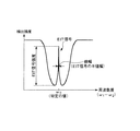
図3は、図1に示すタイミング信号生成装置が備える原子発振器において、アルカリ金属のエネルギー状態を説明するための図である。図4は、図1に示すタイミング信号生成装置が備える原子発振器において、光源部から出射される2つの光の周波数差と、受光部で検出される光の強度との関係を示すグラフである。
アルカリ金属は、図3に示すように、3準位系のエネルギー準位を有し、エネルギー準位の異なる2つの基底状態(基底状態1、2)と、励起状態との3つの状態をとり得る。ここで、基底状態1は、基底状態2よりも低いエネルギー状態である。
Hereinafter, the principle of an atomic oscillator using the EIT phenomenon will be briefly described.
FIG. 3 is a diagram for explaining the energy state of the alkali metal in the atomic oscillator included in the timing signal generation device shown in FIG. FIG. 4 is a graph showing the relationship between the frequency difference between the two lights emitted from the light source unit and the intensity of the light detected by the light receiving unit in the atomic oscillator included in the timing signal generation device shown in FIG.
As shown in FIG. 3, an alkali metal has a three-level energy level and takes three states, two ground states (ground states 1 and 2) having different energy levels, and an excited state. obtain. Here, the ground state 1 is a lower energy state than the ground state 2.
周波数の異なる2種の共鳴光1、2(共鳴光対)を前述したようなガス状のアルカリ金属に照射したとき、共鳴光1の周波数ω1と共鳴光2の周波数ω2との差(ω1−ω2)に応じて、共鳴光1、2のアルカリ金属における光吸収率(光透過率)が変化する。 When two kinds of resonance light 1 and 2 (resonance light pair) having different frequencies are irradiated onto the gaseous alkali metal as described above, the difference between the frequency ω 1 of the resonance light 1 and the frequency ω 2 of the resonance light 2 ( In accordance with (ω 1 −ω 2 ), the light absorptance (light transmittance) of the resonance lights 1 and 2 in the alkali metal changes.
そして、共鳴光1の周波数ω1と共鳴光2の周波数ω2との差(ω1−ω2)が基底状態1と基底状態2とのエネルギー差に相当する周波数に一致したとき、基底状態1、2から励起状態への励起がそれぞれ停止する。このとき、共鳴光1、2は、いずれも、アルカリ金属に吸収されずに透過する。このような現象をCPT現象または電磁誘起透明化現象(EIT)と呼ぶ。 When the difference (ω 1 −ω 2 ) between the frequency ω 1 of the resonant light 1 and the frequency ω 2 of the resonant light 2 coincides with the frequency corresponding to the energy difference between the ground state 1 and the ground state 2, the ground state Excitation from 1, 2 to the excited state stops. At this time, both the resonant lights 1 and 2 are transmitted without being absorbed by the alkali metal. Such a phenomenon is called a CPT phenomenon or an electromagnetically induced transparency phenomenon (EIT).
例えば、共鳴光1の周波数ω1を固定し、共鳴光2の周波数ω2を変化させていくと、共鳴光1の周波数ω1と共鳴光2の周波数ω2との差(ω1−ω2)が基底状態1と基底状態2とのエネルギー差に相当する周波数ω0に一致したとき、アルカリ金属を透過する共鳴光1、2の強度は、図4に示すように、急峻に上昇する。このような急峻な信号をEIT信号として検出する。このEIT信号は、アルカリ金属の種類によって決まった固有値をもっている。したがって、このようなEIT信号を基準信号として用いることにより、高精度な発振器を構成することができる。 For example, when the frequency ω 1 of the resonant light 1 is fixed and the frequency ω 2 of the resonant light 2 is changed, the difference between the frequency ω 1 of the resonant light 1 and the frequency ω 2 of the resonant light 2 (ω 1 −ω When 2 ) coincides with the frequency ω 0 corresponding to the energy difference between the ground state 1 and the ground state 2, the intensities of the resonant lights 1 and 2 that pass through the alkali metal rise sharply as shown in FIG. . Such a steep signal is detected as an EIT signal. This EIT signal has an eigenvalue determined by the type of alkali metal. Therefore, a highly accurate oscillator can be configured by using such an EIT signal as a reference signal.
原子発振器30は、ループフィルター22の出力電圧(制御電圧)に応じて周波数を微調整可能に構成されており、前述のように、位相比較器21、ループフィルター22、DSP23および分周器24により、原子発振器30が出力するクロック信号はGPS受信機10が出力する1PPSに完全に同期する。すなわち、位相比較器21、ループフィルター22、DSP23および分周器24は、PLL(Phase Locked Loop)回路を構成し、原子発振器30が出力するクロック信号を1PPSに同期させる「同期制御部」として機能する。なお、原子発振器30は、単体では周波数温度特性が平坦ではないため、原子発振器30の近傍に、原子発振器30の温度を検出する温度センサー41が配置されており、DSP23は、温度センサー41の検出値(検出温度)に応じて位相比較器21の出力電圧を調整することで、原子発振器30の周波数温度特性を温度補償する処理も行う。 The atomic oscillator 30 is configured so that the frequency can be finely adjusted in accordance with the output voltage (control voltage) of the loop filter 22, and as described above, the phase comparator 21, the loop filter 22, the DSP 23, and the frequency divider 24. The clock signal output from the atomic oscillator 30 is completely synchronized with 1 PPS output from the GPS receiver 10. That is, the phase comparator 21, the loop filter 22, the DSP 23, and the frequency divider 24 constitute a PLL (Phase Locked Loop) circuit and function as a “synchronization control unit” that synchronizes the clock signal output from the atomic oscillator 30 with 1 PPS. To do. Since the atomic oscillator 30 has a non-flat frequency temperature characteristic, a temperature sensor 41 for detecting the temperature of the atomic oscillator 30 is disposed in the vicinity of the atomic oscillator 30, and the DSP 23 detects the temperature sensor 41. By adjusting the output voltage of the phase comparator 21 according to the value (detected temperature), a process for temperature compensating the frequency temperature characteristic of the atomic oscillator 30 is also performed.
また、GPS受信機10が衛星信号を受信できない等の状況(ホールドオーバー)が発生すると、GPS受信機10が出力する1PPSの精度が劣化し、あるいは、GPS受信機10が1PPSの出力を停止する。そのような場合、処理部20は、原子発振器30が出力するクロック信号をGPS受信機10が出力する1PPSに同期させる処理を停止して原子発振器30を自走発振させるようにしてもよい。このようにすれば、タイミング信号生成装置1は、GPS受信機10が出力する1PPSの精度が劣化した場合でも、原子発振器30の自走発振による周波数精度の高い1PPSを出力することができる。なお、原子発振器30に代えてダブルオーブンもしくはシングルオーブンの恒温槽型水晶発振器(OCXO)、電圧制御型水晶発振器(VCXO)、温度補償回路付き水晶発振回路(TCXO)等の水晶発振器を用いても、自走発振による周波数精度の高い1PPSを出力することができる。 In addition, when a situation (holdover) occurs in which the GPS receiver 10 cannot receive a satellite signal, the accuracy of 1 PPS output from the GPS receiver 10 deteriorates, or the GPS receiver 10 stops outputting 1 PPS. . In such a case, the processing unit 20 may stop the process of synchronizing the clock signal output from the atomic oscillator 30 with 1 PPS output from the GPS receiver 10 and cause the atomic oscillator 30 to self-oscillate. In this way, the timing signal generation device 1 can output 1 PPS with high frequency accuracy due to free-running oscillation of the atomic oscillator 30 even when the accuracy of 1 PPS output from the GPS receiver 10 deteriorates. In place of the atomic oscillator 30, a crystal oscillator such as a double oven or single oven thermostat crystal oscillator (OCXO), a voltage controlled crystal oscillator (VCXO), or a crystal oscillation circuit with temperature compensation circuit (TCXO) may be used. 1PPS with high frequency accuracy due to free-running oscillation can be output.
以上説明したような原子発振器30を含むPLL回路において、原子発振器30が故障した場合、原子発振器30のクロック信号とGPS受信機10の1PPS(基準タイミング信号)との位相がずれ(位相のずれが大きくなり)、位相比較器21の出力(位相差信号)が大きくなる。したがって、位相比較器21の出力に基づいて、原子発振器30の故障を検出することができる。本実施形態では、周波数異常判断部27が、位相比較器21の比較結果を用いて、原子発振器30のクロック信号の周波数が異常であるか否かを判断し、周波数が異常である場合には、その判断結果を含む周波数異常情報を出力する。 In the PLL circuit including the atomic oscillator 30 as described above, when the atomic oscillator 30 fails, the phase of the clock signal of the atomic oscillator 30 and the 1PPS (reference timing signal) of the GPS receiver 10 is shifted (the phase shift is The output (phase difference signal) of the phase comparator 21 is increased. Therefore, a failure of the atomic oscillator 30 can be detected based on the output of the phase comparator 21. In the present embodiment, the frequency abnormality determination unit 27 determines whether or not the frequency of the clock signal of the atomic oscillator 30 is abnormal using the comparison result of the phase comparator 21, and when the frequency is abnormal The frequency abnormality information including the determination result is output.
しかし、原子発振器30が実際に故障していなくても、例えば、マイクロ波、電源ノイズ、振動、温度変化等の外乱の影響によって、原子発振器30のクロック信号とGPS受信機10の1PPS(基準タイミング信号)との位相がずれることがある。そのため、位相比較器21の出力のみに基づいて、すなわち、周波数異常判断部27の判断結果のみを用いて、原子発振器30の故障を検出しようとすると、原子発振器30が実際に故障していない場合であっても原子発振器30が故障していると判断してしまうこととなる。また、原子発振器30が実際に故障している場合でも、周波数異常判断部27の判断結果のみに基づいて、原子発振器30が故障しているのか、または、他の部分が故障しているのかが判断できない。したがって、周波数異常判断部27の判断結果のみを報知しても、メンテナンスや修理等が必要ないにもかかわらず、作業員が出向かなければならなかったり、メンテナンスや修理等が必要である場合でも、メンテナンスや修理すべき箇所を特定するのに長時間を要したりして、メンテナンスや修理等の作業効率が悪い。 However, even if the atomic oscillator 30 does not actually fail, the clock signal of the atomic oscillator 30 and the 1 PPS (reference timing) of the GPS receiver 10 are affected by the influence of disturbances such as microwaves, power supply noise, vibration, and temperature change. Signal) may be out of phase. Therefore, when it is attempted to detect a failure of the atomic oscillator 30 based only on the output of the phase comparator 21, that is, using only the determination result of the frequency abnormality determination unit 27, the atomic oscillator 30 is not actually in failure. Even so, it is determined that the atomic oscillator 30 has failed. Even when the atomic oscillator 30 is actually broken, whether the atomic oscillator 30 is broken or whether another part is broken based only on the determination result of the frequency abnormality determining unit 27. I can't judge. Therefore, even if only the determination result of the frequency abnormality determination unit 27 is notified, even if maintenance or repair is not necessary, an operator has to go out or maintenance or repair is necessary. In other words, it takes a long time to specify a place to be maintained or repaired, and the work efficiency of maintenance or repair is poor.
そこで、タイミング信号生成装置1は、前述したような外乱を検出する温度センサー41、マイクロ波受信機42、電源ノイズセンサー43および振動センサー44を有するセンサー部40を設け、判定部28が、周波数異常判断部27の判断結果のみならず、センサー部40の検出結果をも用いて、周波数異常の原因を判定する。 Therefore, the timing signal generation device 1 is provided with a sensor unit 40 having a temperature sensor 41, a microwave receiver 42, a power supply noise sensor 43, and a vibration sensor 44 for detecting disturbance as described above, and the determination unit 28 has a frequency abnormality. The cause of the frequency abnormality is determined using not only the determination result of the determination unit 27 but also the detection result of the sensor unit 40.
以下、周波数異常の判断およびその原因の判定について詳述する。
周波数異常判断部27は、前述したように、位相比較器21の比較結果を用いて、原子発振器30のクロック信号の周波数が異常であるか否かを判断し、その判断結果を含む周波数異常情報を出力する。より具体的には、周波数異常判断部27は、例えば、位相比較器21の出力が所定の設定値以上であるときに、原子発振器30のクロック信号の周波数が異常(いわゆる周波数飛びまたは周波数ズレが生じている状態)であると判断し、その判断結果を出力する。
Hereinafter, determination of frequency abnormality and determination of the cause will be described in detail.
As described above, the frequency abnormality determination unit 27 determines whether or not the frequency of the clock signal of the atomic oscillator 30 is abnormal using the comparison result of the phase comparator 21, and the frequency abnormality information including the determination result. Is output. More specifically, the frequency abnormality determination unit 27 determines that the frequency of the clock signal of the atomic oscillator 30 is abnormal (so-called frequency jump or frequency deviation, for example) when the output of the phase comparator 21 is equal to or higher than a predetermined set value. And the result of the determination is output.
また、周波数異常判断部27は、前述した判断をループフィルター22の時定数に応じた時間間隔(例えば基準タイミング信号の数十周期から数千周期分程度の時間長さ)ごとに行い、当該時間間隔ごとに判断結果を出力することが好ましい。これにより、原子発振器30を有するPLL回路の制御に伴う位相比較器21の出力の揺らぎを周波数異常として判断してしまうのを低減することができる。 In addition, the frequency abnormality determination unit 27 performs the above-described determination for each time interval corresponding to the time constant of the loop filter 22 (for example, a time length of about several tens of cycles to several thousand cycles of the reference timing signal). It is preferable to output a judgment result at every interval. Thereby, it can be reduced that the fluctuation of the output of the phase comparator 21 accompanying the control of the PLL circuit having the atomic oscillator 30 is determined as a frequency abnormality.
また、周波数異常判断部27は、前述した判断を所定時間毎に複数行い、所定回数(例えば2回または3回)以上連続して異常であると判断した場合に、異常である旨の判断結果を出力することが好ましい。これによっても、原子発振器30を有するPLL回路の制御に伴う位相比較器21の出力の揺らぎを周波数異常として判断してしまうのを低減することができる。 In addition, the frequency abnormality determination unit 27 performs a plurality of the above-described determinations every predetermined time, and determines that the abnormality is abnormal when it is determined to be abnormal for a predetermined number of times (for example, twice or three times) continuously. Is preferably output. Also by this, it can be reduced that the fluctuation of the output of the phase comparator 21 accompanying the control of the PLL circuit having the atomic oscillator 30 is determined as a frequency abnormality.
センサー部40は、位相比較器21の比較結果に影響を及ぼす環境情報を検出する。本実施形態では、センサー部40は、温度センサー41、マイクロ波受信機42、電源ノイズセンサー43および振動センサー44を有する。 The sensor unit 40 detects environmental information that affects the comparison result of the phase comparator 21. In the present embodiment, the sensor unit 40 includes a temperature sensor 41, a microwave receiver 42, a power supply noise sensor 43, and a vibration sensor 44.
温度センサー41は、原子発振器30の温度を検出する機能を有する。したがって、センサー部40が検出する環境情報は、当該温度に関する情報を含む。この温度センサー41は、例えば、熱電対またはサーミスタ等を含んで構成されている。 The temperature sensor 41 has a function of detecting the temperature of the atomic oscillator 30. Therefore, the environmental information detected by the sensor unit 40 includes information regarding the temperature. The temperature sensor 41 includes, for example, a thermocouple or a thermistor.
原子発振器30等の発振器は、一般に、温度特性を有し、その温度特性を補正する制御が行われるが、例えば、環境温度が急激に変化すると、その補正が間に合わず、周波数飛びを生じやすい。したがって、このような環境温度の検出結果を用いることで、判定部28において、周波数異常の原因に環境温度による周波数飛びが含まれると判定することができる。 An oscillator such as the atomic oscillator 30 generally has temperature characteristics and is controlled to correct the temperature characteristics. For example, when the environmental temperature changes rapidly, the correction is not in time, and frequency jumps are likely to occur. Therefore, by using such an environmental temperature detection result, the determination unit 28 can determine that a frequency jump due to the environmental temperature is included in the cause of the frequency abnormality.
マイクロ波受信機42は、原子セル内の金属原子の2つの基底準位間のエネルギー差に相当する周波数ω0(例えば、金属原子がセシウム原子である場合、約9.2GHz)のマイクロ波を検出する機能を有する。したがって、センサー部40が検出する環境情報は、当該マイクロ波に関する情報を含む。このマイクロ波受信機42は、例えば、周波数ω0に共振するアンテナと、このアンテナで受信したマイクロ波を増幅する増幅器と、を含んで構成されている。 The microwave receiver 42 receives a microwave having a frequency ω 0 (for example, about 9.2 GHz when the metal atom is a cesium atom) corresponding to the energy difference between the two ground levels of the metal atom in the atomic cell. It has a function to detect. Therefore, the environment information detected by the sensor unit 40 includes information related to the microwave. The microwave receiver 42 includes, for example, an antenna that resonates at a frequency ω 0 and an amplifier that amplifies the microwave received by the antenna.
原子発振器30(30a、30b)は、原子セル内の金属原子の2つの基底準位間のエネルギー差に相当する周波数ω0のマイクロ波が外乱として入力されると、いわゆる周波数飛びが生じやすい。例えば、前述したように、本実施形態のタイミング信号生成装置1では、複数の原子発振器30a、30bを設けておき、必要に応じてこれらを切り換えることにより、ロバスト性を向上させている。このような場合において、使用中の原子発振器に対して他の原子発振器の出力信号によるマイクロ波が入力され、周波数飛びが生じる場合がある。したがって、このようなマイクロ波の検出結果を用いることで、判定部28において、周波数異常の原因にマイクロ波による周波数飛びが含まれると判定することができる。 In the atomic oscillator 30 (30a, 30b), when a microwave having a frequency ω 0 corresponding to an energy difference between two ground levels of metal atoms in an atomic cell is input as a disturbance, a so-called frequency jump is likely to occur. For example, as described above, in the timing signal generation device 1 of the present embodiment, a plurality of atomic oscillators 30a and 30b are provided, and the robustness is improved by switching these as necessary. In such a case, there is a case where a frequency jump occurs due to the input of a microwave from the output signal of another atomic oscillator to the atomic oscillator in use. Therefore, by using such a microwave detection result, the determination unit 28 can determine that the cause of the frequency abnormality includes a frequency jump due to the microwave.
電源ノイズセンサー43は、タイミング信号生成装置1の各部に電力を供給する電源回路60およびその電力供給経路に生じるノイズである電源ノイズを検出する機能を有する。したがって、センサー部40が検出する環境情報は、当該電源ノイズに関する情報を含む。この電源ノイズセンサー43は、例えば、コイルを含んで構成されている。 The power supply noise sensor 43 has a function of detecting power supply noise that is noise generated in the power supply circuit 60 that supplies power to each part of the timing signal generation device 1 and its power supply path. Therefore, the environment information detected by the sensor unit 40 includes information regarding the power supply noise. The power supply noise sensor 43 includes, for example, a coil.
原子発振器30等の発振器は、電源ノイズが外乱として入力されると、周波数飛びを生じやすい。したがって、このような電源ノイズの検出結果を用いることで、判定部28において、周波数異常の原因に電源ノイズによる周波数飛びが含まれると判定することができる。 An oscillator such as the atomic oscillator 30 is likely to cause a frequency jump when power supply noise is input as a disturbance. Therefore, by using such a detection result of the power supply noise, the determination unit 28 can determine that the cause of the frequency abnormality includes a frequency jump due to the power supply noise.
振動センサー44は、原子発振器30が受ける振動を検出する機能を有する。したがって、センサー部40が検出する環境情報は、当該振動に関する情報を含む。この振動センサー44は、例えば、3軸加速度センサーまたは3軸ジャイロセンサー等を含んで構成されている。 The vibration sensor 44 has a function of detecting vibration received by the atomic oscillator 30. Therefore, the environment information detected by the sensor unit 40 includes information related to the vibration. The vibration sensor 44 includes, for example, a three-axis acceleration sensor or a three-axis gyro sensor.
原子発振器30等の発振器は、振動が外乱として入力されると、周波数飛びを生じやすい。したがって、このような振動の検出結果を用いることで、判定部28において、周波数異常の原因に振動による周波数飛びが含まれると判定することができる。 An oscillator such as the atomic oscillator 30 is likely to cause a frequency jump when vibration is input as a disturbance. Therefore, by using such a vibration detection result, the determination unit 28 can determine that the cause of the frequency abnormality includes a frequency jump due to vibration.
判定部28は、周波数異常判断部27の周波数異常情報およびセンサー部40の環境情報を用いて、原子発振器30のクロック信号の周波数の異常の原因を判定する。 The determination unit 28 determines the cause of the frequency abnormality of the clock signal of the atomic oscillator 30 using the frequency abnormality information of the frequency abnormality determination unit 27 and the environmental information of the sensor unit 40.
また、判定部28は、判定結果を出力する「出力部」としての機能を有する。この出力は、例えば、図示しないが、表示装置に入力されたり、通信回線を通じて外部の他の機器に送信されたりする。これにより、装置の使用者や、メンテナンス等の作業者が周波数異常およびその原因を知ることができ、メンテナンスや修理等の作業効率を高めることができる。
判定部28は、例えば、以下のようなステータス情報を判断結果として出力する。
Further, the determination unit 28 has a function as an “output unit” that outputs a determination result. For example, this output is input to a display device or transmitted to another external device through a communication line (not shown). Thereby, the user of the apparatus and the operator such as maintenance can know the frequency abnormality and the cause thereof, and the work efficiency such as maintenance and repair can be improved.
For example, the determination unit 28 outputs the following status information as a determination result.

表1に示すように、原子発振器30のクロック信号の周波数が異常である旨の判断結果を含む周波数異常情報が周波数異常判断部27から出力されている時間長さが所定時間(例えば1秒)以上である場合、周波数異常が周波数ズレ(Fズレ)であると判定する。これにより、作業者等は、この判定結果に基づき、原子発振器30等に何らかの故障があると原因を絞ることができる。 As shown in Table 1, the time length during which the frequency abnormality information including the determination result that the frequency of the clock signal of the atomic oscillator 30 is abnormal is output from the frequency abnormality determination unit 27 is a predetermined time (for example, 1 second). When it is above, it is determined that the frequency abnormality is a frequency shift (F shift). Thereby, the operator or the like can narrow down the cause if there is any failure in the atomic oscillator 30 or the like based on the determination result.
一方、原子発振器30のクロック信号の周波数が異常である旨の判断結果を含む周波数異常情報が周波数異常判断部27から出力されている時間長さが所定時間(例えば1秒)未満である場合、周波数異常に周波数飛び(F飛び)が含まれると判定する。これにより、作業者等は、この判定結果に基づき、原子発振器30以外に故障があるか、または、外乱による一時的な周波数飛びであると原因を絞ることができる。 On the other hand, when the time length during which the frequency abnormality information including the determination result that the frequency of the clock signal of the atomic oscillator 30 is abnormal is output from the frequency abnormality determination unit 27 is less than a predetermined time (for example, 1 second), It is determined that the frequency abnormality includes a frequency jump (F jump). Thus, the operator or the like can narrow down the cause based on the determination result if there is a failure other than the atomic oscillator 30 or if the frequency jump is temporarily caused by a disturbance.
また、ステータス情報には、このような周波数飛びまたは周波数ズレである旨の判定結果に加えて、温度センサー41、マイクロ波受信機42、電源ノイズセンサー43および振動センサー44の検出結果に基づく判定結果を付加する。 The status information includes a determination result based on detection results of the temperature sensor 41, the microwave receiver 42, the power supply noise sensor 43, and the vibration sensor 44 in addition to the determination result indicating that the frequency jump or frequency deviation is present. Is added.
具体的には、温度センサー41の検出結果に基づき、短期間(例えば1秒間〜10秒間)に温度が比較的大きく(例えば5℃以上)変動した場合、その旨(急激な温度変化)の判定結果をステータス情報に付加する。あるいは、周波数異常が発生している間の温度の変遷情報をステータス情報に付加してもよい。 Specifically, based on the detection result of the temperature sensor 41, when the temperature fluctuates relatively large (for example, 5 ° C. or more) in a short period (for example, 1 second to 10 seconds), a determination to that effect (rapid temperature change) Append the result to the status information. Alternatively, temperature transition information while the frequency abnormality is occurring may be added to the status information.
また、マイクロ波受信機42の検出結果に基づき、周波数ω0のマイクロ波が外乱として入力された場合、その旨(マイクロ波外乱)の判定結果をステータス情報に付加する。 Further, when a microwave with a frequency ω 0 is input as a disturbance based on the detection result of the microwave receiver 42, a determination result to that effect (microwave disturbance) is added to the status information.
また、電源ノイズセンサー43の検出結果に基づき、電源ノイズが外乱として入力された場合、その旨(電源ノイズ)の判定結果をステータス情報に付加する。 If power noise is input as a disturbance based on the detection result of the power noise sensor 43, a determination result indicating that (power noise) is added to the status information.
また、振動センサー44の検出結果に基づき、振動が外乱として入力された場合、その旨(振動)の判定結果をステータス情報に付加する。 Further, when vibration is input as disturbance based on the detection result of the vibration sensor 44, a determination result to that effect (vibration) is added to the status information.
以上説明したようなタイミング信号生成装置1によれば、判定部28が、周波数異常判断部27の判断結果のみならず、センサー部40の検出結果をも用いて、周波数異常の原因を判定するため、原子発振器30のクロック信号の異常の原因を絞ることができ、その結果、メンテナンスや修理等の作業効率を高めることができる。 According to the timing signal generating apparatus 1 as described above, the determination unit 28 determines not only the determination result of the frequency abnormality determination unit 27 but also the detection result of the sensor unit 40 to determine the cause of the frequency abnormality. The cause of the abnormality of the clock signal of the atomic oscillator 30 can be narrowed down, and as a result, the work efficiency of maintenance, repair, etc. can be improved.
2.電子機器
次に、本発明の電子機器の実施形態を説明する。
図5は、本発明の電子機器の実施形態を示すブロック図である。
2. Next, an embodiment of an electronic device of the present invention will be described.
FIG. 5 is a block diagram showing an embodiment of the electronic apparatus of the present invention.
図5に示す電子機器300は、タイミング信号生成装置310、CPU(Central Processing Unit)320、操作部330、ROM(Read Only Memory)340、RAM(Random Access Memory)350、通信部360および表示部370を含んで構成されている。
5 includes a timing
タイミング信号生成装置310は、例えば、前述したタイミング信号生成装置1であり、先に説明したように、衛星信号を受信して高精度のタイミング信号(1PPS)を生成し、外部に出力する。これにより、より低コストで信頼性の高い電子機器300を実現することができる。
The timing
CPU320は、ROM340等に記憶されているプログラムに従い、各種の計算処理や制御処理を行う。具体的には、CPU320は、タイミング信号生成装置310が出力するタイミング信号(1PPS)やクロック信号に同期して、計時処理、操作部330からの操作信号に応じた各種の処理、外部とデータ通信を行うために通信部360を制御する処理、表示部370に各種の情報を表示させるための表示信号を送信する処理等を行う。
The
操作部330は、操作キーやボタンスイッチ等により構成される入力装置であり、ユーザーによる操作に応じた操作信号をCPU320に出力する。
The
ROM340は、CPU320が各種の計算処理や制御処理を行うためのプログラムやデータ等を記憶している。
The
RAM350は、CPU320の作業領域として用いられ、ROM340から読み出されたプログラムやデータ、操作部330から入力されたデータ、CPU320が各種プログラムにしたがって実行した演算結果等を一時的に記憶する。
The
通信部360は、CPU320と外部装置との間のデータ通信を成立させるための各種制御を行う。
The
表示部370は、LCD(Liquid Crystal Display)等により構成される表示装置であり、CPU320から入力される表示信号に基づいて各種の情報を表示する。表示部370には操作部330として機能するタッチパネルが設けられていてもよい。
The
このような電子機器300としては種々の電子機器が考えられ、特に限定されないが、例えば、標準時刻との同期を実現する時刻管理用のサーバー(タイムサーバー)、タイムスタンプの発行等を行う時刻管理装置(タイムスタンプサーバー)、基地局等の周波数基準装置等が挙げられる。 Various electronic devices are conceivable as such an electronic device 300, and are not particularly limited. For example, a time management server that realizes synchronization with a standard time (time server), time management that issues time stamps, and the like Examples include devices (time stamp servers) and frequency reference devices such as base stations.
3.移動体
図6は、本発明の移動体の実施形態を示す図である。
3. Mobile Object FIG. 6 is a diagram showing an embodiment of the mobile object of the present invention.
図6に示す移動体400は、タイミング信号生成装置410、カーナビゲーション装置420、コントローラー430、440、450、バッテリー460、バックアップ用バッテリー470を含んで構成されている。
6 includes a timing signal generation device 410, a
タイミング信号生成装置410としては、前述したタイミング信号生成装置1を適用することができる。タイミング信号生成装置410は、例えば、移動体400が移動中は、通常測位モードでリアルタイムに測位計算を行って1PPS、クロック信号およびNMEAデータを出力する。また、タイミング信号生成装置410は、例えば、移動体400が停止中は、通常測位モードで複数回の測位計算を行った後、複数回の測位計算結果の最頻値または中央値を現在の位置情報として設定し、位置固定モードで1PPS、クロック信号およびNMEAデータを出力する。
As the timing signal generation device 410, the timing signal generation device 1 described above can be applied. For example, when the moving
カーナビゲーション装置420は、タイミング信号生成装置410が出力する1PPSやクロック信号に同期して、タイミング信号生成装置410が出力するNMEAデータを用いて、位置や時刻その他の各種の情報をディスプレイに表示する。
The
コントローラー430、440、450は、エンジンシステム、ブレーキシステム、キーレスエントリーシステム等の各種の制御を行う。コントローラー430、440、450は、タイミング信号生成装置410が出力するクロック信号に同期して各種の制御を行うようにしてもよい。
The
本実施形態の移動体400は、タイミング信号生成装置410を備えていることで、移動中も停止中も高い信頼性を確保することができる。
Since the moving
このような移動体400としては種々の移動体が考えられ、例えば、自動車(電気自動車も含む)、ジェット機やヘリコプター等の航空機、船舶、ロケット、人工衛星等が挙げられる。
As such a moving
以上、本発明のタイミング信号生成装置、電子機器および移動体について、図示の実施形態に基づいて説明したが、本発明は、これらに限定されるものではない。 As described above, the timing signal generation device, the electronic apparatus, and the moving body of the present invention have been described based on the illustrated embodiments, but the present invention is not limited to these.
また、本発明は、前述した実施形態の同様の機能を発揮する任意の構成のものに置換することができ、また、任意の構成を付加することもできる。 In addition, the present invention can be replaced with an arbitrary configuration that exhibits the same function as that of the above-described embodiment, and an arbitrary configuration can be added.
また、前述した実施形態では、GPSを利用したタイミング信号生成装置を例に挙げたが、GPS以外の全地球的航法衛星システム(GNSS)、例えば、ガリレオ、GLONASS等を利用してもよい。 In the above-described embodiment, the timing signal generation device using GPS is taken as an example, but a global navigation satellite system (GNSS) other than GPS, for example, Galileo, GLONASS, or the like may be used.
また、前述した実施形態では、センサー部が、温度センサー、マイクロ波受信機、電源ノイズセンサーおよび振動センサーを備える場合を例に説明したが、これらのセンサーのうちの少なくとも1つをセンサー部が有していれば、他のセンサーを省略してもよい。また、センサー部が備えるセンサーとしては、位相比較器の出力結果に影響を与える環境(外乱)を検出し得るものであれば、前述したものに限らず、例えば、気圧センサー、光センサー等を用いてもよい。 In the above-described embodiment, the case where the sensor unit includes a temperature sensor, a microwave receiver, a power supply noise sensor, and a vibration sensor has been described as an example. However, at least one of these sensors has the sensor unit. If so, other sensors may be omitted. In addition, the sensor provided in the sensor unit is not limited to the above-described sensor as long as it can detect an environment (disturbance) that affects the output result of the phase comparator. May be.
1‥‥タイミング信号生成装置
2‥‥GPS衛星
10‥‥GPS受信機
11‥‥SAWフィルター
12‥‥RF処理部
13‥‥ベースバンド処理部
14‥‥TCXO
20‥‥処理部
21‥‥位相比較器
22‥‥ループフィルター
23‥‥DSP
24‥‥分周器
25‥‥GPS制御部
27‥‥周波数異常判断部
28‥‥判定部
30‥‥原子発振器
30a‥‥原子発振器
30b‥‥原子発振器
40‥‥センサー部
41‥‥温度センサー
42‥‥マイクロ波受信機
43‥‥電源ノイズセンサー
44‥‥振動センサー
50‥‥GPSアンテナ
60‥‥電源回路
121‥‥PLL
122‥‥LNA
123‥‥ミキサー
124‥‥IFアンプ
125‥‥IFフィルター
126‥‥ADC
131‥‥DSP
132‥‥CPU
133‥‥SRAM
134‥‥RTC
300‥‥電子機器
310‥‥タイミング信号生成装置
320‥‥CPU
330‥‥操作部
340‥‥ROM
350‥‥RAM
360‥‥通信部
370‥‥表示部
400‥‥移動体
410‥‥タイミング信号生成装置
420‥‥カーナビゲーション装置
430‥‥コントローラー
440‥‥コントローラー
450‥‥コントローラー
460‥‥バッテリー
470‥‥バックアップ用バッテリー
ω0‥‥周波数
ω1‥‥周波数
ω2‥‥周波数
DESCRIPTION OF SYMBOLS 1 ... Timing signal generator 2 ... GPS satellite 10 ...
20. Processing unit 21 ... Phase comparator 22 ... Loop filter 23 ... DSP
24... Frequency divider 25... GPS controller 27... Frequency abnormality determination unit 28 .. Judgment unit 30 .. Atomic oscillator 30a ... Atomic oscillator 30b ... Atomic oscillator 40 ... Sensor unit 41 ... Temperature sensor 42 Microwave receiver 43 Power supply noise sensor 44
122 ... LNA
123 ...
131 ... DSP
132 ... CPU
133 ... SRAM
134 ... RTC
300 ...
330 ...
350 ... RAM
360 ...
Claims (8)
前記基準タイミング信号に同期させるためのクロック信号を出力する発振器と、
前記基準タイミング信号と前記クロック信号との位相を比較する位相比較器と、
前記位相比較器の比較結果を用いて、前記クロック信号の周波数が異常であるか否かを判断し、その判断結果を含む周波数異常情報を出力する周波数異常判断部と、
環境情報を検出するセンサー部と、
前記周波数異常情報および前記環境情報を用いて、前記異常の原因を判定する判定部と、
を備え、
前記発振器は、互いに異なる2つの基底準位を有する金属原子のエネルギー遷移に基づいて発振する原子発振器であり、
前記センサー部は、前記2つの基底準位間のエネルギー差に相当する周波数のマイクロ波を検出可能なマイクロ波受信機を有し、
前記環境情報は、前記マイクロ波に関する情報を含むことを特徴とするタイミング信号生成装置。 A reference timing signal output unit for outputting a reference timing signal;
An oscillator that outputs a clock signal for synchronizing with the reference timing signal;
A phase comparator that compares the phases of the reference timing signal and the clock signal;
Using the comparison result of the phase comparator, it is determined whether or not the frequency of the clock signal is abnormal, and a frequency abnormality determination unit that outputs frequency abnormality information including the determination result;
A sensor unit for detecting environmental information;
A determination unit that determines the cause of the abnormality using the frequency abnormality information and the environment information;
Equipped with a,
The oscillator is an atomic oscillator that oscillates based on energy transition of a metal atom having two different ground levels.
The sensor unit includes a microwave receiver capable of detecting a microwave having a frequency corresponding to an energy difference between the two ground levels,
The timing information generating apparatus , wherein the environment information includes information on the microwave .
前記環境情報は、前記振動に関する情報を含む請求項1に記載のタイミング信号生成装置。 The sensor unit has a vibration sensor capable of detecting vibration received by the oscillator,
The timing signal generation device according to claim 1, wherein the environmental information includes information related to the vibration.
前記環境情報は、前記電源ノイズに関する情報を含む請求項1または2に記載のタイミング信号生成装置。 The sensor unit has a power supply noise sensor capable of detecting power supply noise,
The environmental information includes a timing signal generating device according to claim 1 or 2 containing information on the power supply noise.
前記環境情報は、前記温度に関する情報を含む請求項1ないし3のいずれか1項に記載のタイミング信号生成装置。 The sensor unit has a temperature sensor capable of detecting the temperature of the oscillator,
The environmental information includes a timing signal generating device according to any one of claims 1 to 3 containing information about the temperature.
Priority Applications (4)
| Application Number | Priority Date | Filing Date | Title |
|---|---|---|---|
| JP2015107644A JP6589375B2 (en) | 2015-05-27 | 2015-05-27 | Timing signal generating device, electronic device, and moving object |
| CN201610313172.3A CN106209078B (en) | 2015-05-27 | 2016-05-12 | Timing signal generation device, electronic apparatus, and moving object |
| US15/160,160 US9979409B2 (en) | 2015-05-27 | 2016-05-20 | Timing signal generation device, electronic device, and moving object |
| US15/955,174 US10700690B2 (en) | 2015-05-27 | 2018-04-17 | Timing signal generation device, electronic device, and moving object |
Applications Claiming Priority (1)
| Application Number | Priority Date | Filing Date | Title |
|---|---|---|---|
| JP2015107644A JP6589375B2 (en) | 2015-05-27 | 2015-05-27 | Timing signal generating device, electronic device, and moving object |
Publications (3)
| Publication Number | Publication Date |
|---|---|
| JP2016225708A JP2016225708A (en) | 2016-12-28 |
| JP2016225708A5 JP2016225708A5 (en) | 2018-06-14 |
| JP6589375B2 true JP6589375B2 (en) | 2019-10-16 |
Family
ID=57397606
Family Applications (1)
| Application Number | Title | Priority Date | Filing Date |
|---|---|---|---|
| JP2015107644A Active JP6589375B2 (en) | 2015-05-27 | 2015-05-27 | Timing signal generating device, electronic device, and moving object |
Country Status (3)
| Country | Link |
|---|---|
| US (2) | US9979409B2 (en) |
| JP (1) | JP6589375B2 (en) |
| CN (1) | CN106209078B (en) |
Families Citing this family (11)
| Publication number | Priority date | Publication date | Assignee | Title |
|---|---|---|---|---|
| US10222482B2 (en) * | 2013-01-18 | 2019-03-05 | Seiko Epson Corporation | Position information generation device, timing signal generation device, electronic apparatus, and moving object |
| EP4084574A1 (en) * | 2013-06-04 | 2022-11-02 | Attobahn Inc. | Viral molecular network architecture and design |
| US11889590B2 (en) * | 2013-06-04 | 2024-01-30 | Attobahn, Inc. | System and method for a viral molecular network utilizing mobile devices |
| JP6589375B2 (en) * | 2015-05-27 | 2019-10-16 | セイコーエプソン株式会社 | Timing signal generating device, electronic device, and moving object |
| JP2017118371A (en) * | 2015-12-25 | 2017-06-29 | セイコーエプソン株式会社 | Timing signal generation device, electronic apparatus and mobile |
| US10903974B2 (en) * | 2018-07-25 | 2021-01-26 | Sirius Xm Radio Inc. | Maintaining repeater accuracy for satellite signal delivery systems |
| JP7238464B2 (en) * | 2019-02-26 | 2023-03-14 | セイコーエプソン株式会社 | Real-time clock modules, electronic devices and moving objects |
| CN111208539B (en) * | 2019-12-18 | 2023-06-23 | 中国航空工业集团公司成都飞机设计研究所 | High-precision GNSS simulator time synchronization method |
| CN112346090A (en) * | 2020-09-25 | 2021-02-09 | 深圳星标科技股份有限公司 | Timing synchronization method, visual navigation aid equipment control method and related device |
| EP4130929A1 (en) | 2021-08-04 | 2023-02-08 | Orolia Defense & Security LLC | Real time clock integrated module and device implementing such a module |
| FR3130103A1 (en) * | 2021-12-07 | 2023-06-09 | Spectracom Sas | Very high precision clock module controlled by a reference signal and including a phase integrity verification system |
Family Cites Families (22)
| Publication number | Priority date | Publication date | Assignee | Title |
|---|---|---|---|---|
| JPS57210730A (en) * | 1981-06-19 | 1982-12-24 | Fujitsu Ltd | Oscillation monitoring circuit |
| JP3220496B2 (en) * | 1992-02-10 | 2001-10-22 | 日本電信電話株式会社 | Electromagnetic environment measurement device |
| US7887407B1 (en) * | 1997-05-23 | 2011-02-15 | Ptt, Llc. | Method of extending play of a slot machine game |
| US6928275B1 (en) * | 2000-05-08 | 2005-08-09 | Qualcomm Incorporated | Method and apparatus for compensating local oscillator frequency error |
| JP4515646B2 (en) | 2001-01-22 | 2010-08-04 | マスプロ電工株式会社 | Reference frequency generator |
| CN101098141B (en) * | 2006-06-29 | 2012-05-30 | 日本电波工业株式会社 | Frequency synthesizer |
| JP2009302912A (en) * | 2008-06-13 | 2009-12-24 | Fujitsu Telecom Networks Ltd | Clock generation circuit |
| JP5011559B2 (en) * | 2008-10-03 | 2012-08-29 | 古野電気株式会社 | Reference signal generator |
| US7932757B2 (en) * | 2008-11-12 | 2011-04-26 | Qualcomm Incorporated | Techniques for minimizing control voltage ripple due to charge pump leakage in phase locked loop circuits |
| JP5039073B2 (en) * | 2009-02-25 | 2012-10-03 | 古野電気株式会社 | Reference frequency generator |
| US8456302B2 (en) * | 2009-07-14 | 2013-06-04 | Savi Technology, Inc. | Wireless tracking and monitoring electronic seal |
| JP5688905B2 (en) * | 2010-01-26 | 2015-03-25 | 古野電気株式会社 | Reference frequency generator |
| JP5016074B2 (en) * | 2010-02-16 | 2012-09-05 | 日本電波工業株式会社 | PLL circuit |
| CN102033226B (en) * | 2010-12-06 | 2013-01-02 | 复旦大学 | Method for improving monitoring distance of single-core feedback optical fiber sensing technology and optical fiber interference structure |
| CN102253379B (en) * | 2011-04-11 | 2013-01-30 | 中国人民解放军理工大学 | System for monitoring landslide based on radio interference technology |
| CN102801415B (en) * | 2011-05-23 | 2016-08-17 | 上海航天测控通信研究所 | A kind of management device for frequency synthesizer |
| US9405012B2 (en) * | 2012-04-12 | 2016-08-02 | Trimble Navigation Limited | Advanced global navigation satellite systems (GNSS) positioning using precise satellite information |
| JP6175775B2 (en) * | 2013-01-18 | 2017-08-09 | セイコーエプソン株式会社 | Timing signal generating device, electronic device and moving body |
| JP6127573B2 (en) * | 2013-02-21 | 2017-05-17 | セイコーエプソン株式会社 | Oscillator and electronic device |
| KR102161821B1 (en) * | 2014-08-26 | 2020-10-06 | 삼성전자주식회사 | Clock monitor and system on chip including the same |
| CN104485947B (en) * | 2014-12-30 | 2017-10-27 | 中南民族大学 | A kind of digital phase discriminator that crystal oscillator is tamed for GPS |
| JP6589375B2 (en) * | 2015-05-27 | 2019-10-16 | セイコーエプソン株式会社 | Timing signal generating device, electronic device, and moving object |
-
2015
- 2015-05-27 JP JP2015107644A patent/JP6589375B2/en active Active
-
2016
- 2016-05-12 CN CN201610313172.3A patent/CN106209078B/en active Active
- 2016-05-20 US US15/160,160 patent/US9979409B2/en active Active
-
2018
- 2018-04-17 US US15/955,174 patent/US10700690B2/en active Active
Also Published As
| Publication number | Publication date |
|---|---|
| CN106209078A (en) | 2016-12-07 |
| CN106209078B (en) | 2021-06-04 |
| US20160352344A1 (en) | 2016-12-01 |
| US20180234100A1 (en) | 2018-08-16 |
| US9979409B2 (en) | 2018-05-22 |
| US10700690B2 (en) | 2020-06-30 |
| JP2016225708A (en) | 2016-12-28 |
Similar Documents
| Publication | Publication Date | Title |
|---|---|---|
| JP6589375B2 (en) | Timing signal generating device, electronic device, and moving object | |
| US10187074B2 (en) | Timing signal generation device, electronic device, and moving object | |
| JP6175775B2 (en) | Timing signal generating device, electronic device and moving body | |
| JP6627489B2 (en) | Timing signal generator and electronic equipment | |
| JP6485141B2 (en) | Timing signal generator and electronic device | |
| JP6379549B2 (en) | Timing signal generating apparatus and electronic device | |
| US10168434B2 (en) | Reference signal generation device, electronic device, moving object, data communication device, and terrestrial digital communication network | |
| JP6201585B2 (en) | Timing signal generating device, electronic device, and moving object | |
| US10222482B2 (en) | Position information generation device, timing signal generation device, electronic apparatus, and moving object | |
| US9762341B2 (en) | Time synchronization system | |
| JP2017216612A (en) | Timing signal generation device, electronic apparatus, and mobile body | |
| US20180246216A1 (en) | Timing signal output device, and electronic apparatus | |
| JP6264973B2 (en) | Timing signal generating device, electronic device, and moving object | |
| JP6753068B2 (en) | Timing signal generators and electronic devices | |
| JP2017138197A (en) | Timing signal generating device, electronic equipment, and mobile body | |
| JP6485501B2 (en) | Signal generation method | |
| JP2016195347A (en) | Timing signal generator, electronic apparatus and moving body | |
| JP6361354B2 (en) | Positioning device, timing signal generating device, electronic device, and moving object | |
| JP2017138234A (en) | Timing signal generating device, electronic equipment, and mobile body | |
| JP2017059971A (en) | Timing signal generator, electronic apparatus and movable body |
Legal Events
| Date | Code | Title | Description |
|---|---|---|---|
| A521 | Request for written amendment filed |
Free format text: JAPANESE INTERMEDIATE CODE: A523 Effective date: 20180502 |
|
| A621 | Written request for application examination |
Free format text: JAPANESE INTERMEDIATE CODE: A621 Effective date: 20180502 |
|
| A131 | Notification of reasons for refusal |
Free format text: JAPANESE INTERMEDIATE CODE: A131 Effective date: 20190226 |
|
| A977 | Report on retrieval |
Free format text: JAPANESE INTERMEDIATE CODE: A971007 Effective date: 20190227 |
|
| A521 | Request for written amendment filed |
Free format text: JAPANESE INTERMEDIATE CODE: A523 Effective date: 20190417 |
|
| TRDD | Decision of grant or rejection written | ||
| A01 | Written decision to grant a patent or to grant a registration (utility model) |
Free format text: JAPANESE INTERMEDIATE CODE: A01 Effective date: 20190820 |
|
| A61 | First payment of annual fees (during grant procedure) |
Free format text: JAPANESE INTERMEDIATE CODE: A61 Effective date: 20190902 |
|
| R150 | Certificate of patent or registration of utility model |
Ref document number: 6589375 Country of ref document: JP Free format text: JAPANESE INTERMEDIATE CODE: R150 |
|
| R250 | Receipt of annual fees |
Free format text: JAPANESE INTERMEDIATE CODE: R250 |
|
| S111 | Request for change of ownership or part of ownership |
Free format text: JAPANESE INTERMEDIATE CODE: R313113 |
|
| R350 | Written notification of registration of transfer |
Free format text: JAPANESE INTERMEDIATE CODE: R350 |