JP2017138234A - Timing signal generating device, electronic equipment, and mobile body - Google Patents
Timing signal generating device, electronic equipment, and mobile body Download PDFInfo
- Publication number
- JP2017138234A JP2017138234A JP2016020139A JP2016020139A JP2017138234A JP 2017138234 A JP2017138234 A JP 2017138234A JP 2016020139 A JP2016020139 A JP 2016020139A JP 2016020139 A JP2016020139 A JP 2016020139A JP 2017138234 A JP2017138234 A JP 2017138234A
- Authority
- JP
- Japan
- Prior art keywords
- timing signal
- gps receiver
- mask
- elevation angle
- gps
- Prior art date
- Legal status (The legal status is an assumption and is not a legal conclusion. Google has not performed a legal analysis and makes no representation as to the accuracy of the status listed.)
- Pending
Links
Images


Abstract
Description
本発明は、タイミング信号生成装置、電子機器および移動体に関する。 The present invention relates to a timing signal generation device, an electronic device, and a moving object.
人工衛星を利用した全地球航法衛星システム(GNSS:Global Navigation Satellite System)の1つであるGPS(Global Positioning System)が広く知られている。GPSに用いるGPS衛星は、極めて精度の高い原子時計が搭載されており、GPS衛星の軌道情報や正確な時刻情報等が重畳された衛星信号を地上に送信している。GPS衛星から送信された衛星信号は、GPS受信機で受信される。そして、GPS受信機は、衛星信号に重畳されている軌道情報や時刻情報に基づいてGPS受信機の現在位置や時刻情報を算出する処理や、協定世界時(UTC:Coordinated Universal Time)に同期した正確なタイミング信号(1PPS)を生成する処理等を行う。 A GPS (Global Positioning System) that is one of Global Navigation Satellite System (GNSS) using an artificial satellite is widely known. A GPS satellite used for GPS is equipped with an extremely accurate atomic clock, and transmits a satellite signal on which orbit information, accurate time information, and the like of the GPS satellite are superimposed on the ground. A satellite signal transmitted from a GPS satellite is received by a GPS receiver. The GPS receiver is synchronized with a process of calculating the current position and time information of the GPS receiver based on orbit information and time information superimposed on the satellite signal, and Coordinated Universal Time (UTC). A process for generating an accurate timing signal (1PPS) is performed.
このようなGPS受信機は、測位計算に基づき、位置・時刻を提供する通常測位(位置推定)モードと、既知位置での固定位置測位による時刻提供をする位置固定モードが設けられているのが一般的である。 Such a GPS receiver is provided with a normal positioning (position estimation) mode for providing position and time based on positioning calculation and a position fixing mode for providing time by fixed position positioning at a known position. It is common.
通常測位モードでは、所定数(2次元測位であれば最低3個、3次元測位であれば4個)以上のGPS衛星からの衛星信号が必要である。また、衛星信号を受信可能なGPS衛星の数が多いほど、測位計算の精度が向上する。 In the normal positioning mode, satellite signals from GPS satellites of a predetermined number (minimum of three for two-dimensional positioning or four for three-dimensional positioning) or more are required. Also, the greater the number of GPS satellites that can receive satellite signals, the more accurate the positioning calculation.
これに対して、位置固定モードでは、GPS受信機の位置情報が設定されていれば、少なくとも1つのGPS衛星からの衛星信号を受信できれば1PPSを生成することができる。 On the other hand, in the position fixing mode, if the position information of the GPS receiver is set, 1 PPS can be generated if the satellite signal from at least one GPS satellite can be received.
位置固定モードでの1PPSの精度は、設定される位置情報の精度に依存するため、GPS受信機に正確な位置情報を設定することが重要になる。特許文献1では、設置したGPS受信機自体が測位計算を行い、測位結果の位置情報を所定時間に亘って平均化して受信点の位置を決定する手法が提案されており、この手法によれば、任意の受信場所での位置情報を取得することが可能であり、コストも低減することができる。 Since the accuracy of 1PPS in the fixed position mode depends on the accuracy of the set position information, it is important to set accurate position information in the GPS receiver. Patent Document 1 proposes a method in which the installed GPS receiver itself performs positioning calculation and averages position information of the positioning result over a predetermined time to determine the position of the reception point. In addition, it is possible to acquire position information at an arbitrary reception place, and the cost can be reduced.
しかしながら、特許文献1の手法では、マルチパス等何らかのエラーが発生した場合には測位計算の結果の位置情報に大きな誤差が含まれるため、受信点の位置の誤差が大きくなる可能性がある。そのため、特許文献1の手法では、測位計算時の受信環境によっては1PPS(タイミング信号)の精度が劣化するおそれがあるという問題がある。このような問題は、GPS受信機だけでなく、その他の全地球航法衛星システム(GNSS)の受信装置についても共通の問題である。 However, in the method of Patent Document 1, if any error such as multipath occurs, the position information obtained as a result of the positioning calculation includes a large error, and thus the position error of the reception point may increase. Therefore, the method of Patent Document 1 has a problem that the accuracy of 1 PPS (timing signal) may be deteriorated depending on the reception environment at the time of positioning calculation. Such a problem is common to not only GPS receivers but also other global navigation satellite system (GNSS) receivers.
本発明の目的は、受信環境が劣化しても、受信点の位置を高精度に算出して、高精度なタイミング信号を生成することができるタイミング信号生成装置を提供すること、また、かかるタイミング信号生成装置を備える電子機器および移動体を提供することにある。 An object of the present invention is to provide a timing signal generation device capable of calculating a position of a reception point with high accuracy and generating a highly accurate timing signal even when the reception environment is deteriorated, and to provide such timing. An object of the present invention is to provide an electronic device including a signal generation device and a moving body.
このような目的は、下記の本発明により達成される。
本発明のタイミング信号生成装置は、第1仰角マスクを用いて衛星信号を受信し、第1タイミング信号を出力する第1受信機と、
第2仰角マスクを用いて前記衛星信号を受信し、第2タイミング信号を出力する第2受信機と、
前記第1タイミング信号と前記第2タイミング信号との位相を比較する位相比較器と、
前記位相比較器の比較結果を用いて、前記第1仰角マスクおよび前記第2仰角マスクのうちの少なくとも一方の設定値を調整する調整部と、を備えることを特徴とする。
Such an object is achieved by the present invention described below.
A timing signal generator of the present invention includes a first receiver that receives a satellite signal using a first elevation mask and outputs a first timing signal;
A second receiver for receiving the satellite signal using a second elevation mask and outputting a second timing signal;
A phase comparator that compares the phases of the first timing signal and the second timing signal;
An adjustment unit that adjusts a set value of at least one of the first elevation mask and the second elevation mask using a comparison result of the phase comparator.
このようなタイミング信号生成装置によれば、位相比較器の比較結果に基づいて、第1受信機または第2受信機がマルチパスの影響を受けているか否かを判断することができる。したがって、その判断結果を用いることで、第1仰角マスクまたは第2仰角マスクの設定値をマルチパスの影響を受けないように調整することができる。そして、その調整後の第1受信機または第2受信機の測位計算結果を用いて受信点の位置を算出することで、高精度な位置算出(真位置の算出)が可能となる。よって、受信環境が劣化しても、受信点の位置を高精度に算出して、高精度なタイミング信号を生成することができる。 According to such a timing signal generation device, it is possible to determine whether or not the first receiver or the second receiver is affected by multipath based on the comparison result of the phase comparator. Therefore, by using the determination result, the set value of the first elevation angle mask or the second elevation angle mask can be adjusted so as not to be affected by the multipath. Then, by calculating the position of the reception point using the positioning calculation result of the adjusted first receiver or second receiver, highly accurate position calculation (true position calculation) is possible. Therefore, even if the reception environment deteriorates, the position of the reception point can be calculated with high accuracy, and a highly accurate timing signal can be generated.
本発明のタイミング信号生成装置では、クロック信号を出力する発振器と、
前記クロック信号を前記第1タイミング信号に同期させる同期制御部と、を備え、
前記調整部は、前記第1仰角マスクおよび前記第2仰角マスクを互いに異なる設定値に設定し、前記位相比較器の比較結果を用いて、前記第1仰角マスクの設定値を調整することが好ましい。
In the timing signal generation device of the present invention, an oscillator that outputs a clock signal;
A synchronization controller for synchronizing the clock signal with the first timing signal,
Preferably, the adjustment unit sets the first elevation angle mask and the second elevation angle mask to different set values, and uses the comparison result of the phase comparator to adjust the set value of the first elevation angle mask. .
これにより、第1仰角マスクの設定値をマルチパスの影響を受けないように調整し、発振器のクロック信号を第1タイミング信号に同期した高精度なタイミング信号として出力することができる。 Thus, the set value of the first elevation mask can be adjusted so as not to be affected by multipath, and the clock signal of the oscillator can be output as a highly accurate timing signal synchronized with the first timing signal.
本発明のタイミング信号生成装置では、前記調整部は、前記第1仰角マスクの設定値を前記第2仰角マスクの設定値よりも小さい値に設定し、前記位相比較器の比較結果を用いて、前記第1仰角マスクの設定値を前記第2仰角マスクの設定値に近づく側の値に段階的に調整することが好ましい。 In the timing signal generation device of the present invention, the adjustment unit sets the setting value of the first elevation mask to a value smaller than the setting value of the second elevation mask, and uses the comparison result of the phase comparator, It is preferable to adjust the set value of the first elevation angle mask stepwise to a value closer to the set value of the second elevation angle mask.
第1仰角マスクの設定値を第2仰角マスクの設定値よりも小さい値に設定したとき、第1受信機が、第2受信機に比べて、捕捉可能な衛星信号の数が多くなり、マルチパスの影響を受けやすくなる。言い換えると、このとき、第2受信機が、第1受信機に比べて、捕捉可能な衛星信号の数が少なくなるものの、マルチパスの影響を受けづらくなる。したがって、第2仰角マスクの設定値をマルチパスの影響を受けないように大きく設定した状態で第1受信機がマルチパスを受けた場合、第1受信機のタイミング信号にはマルチパスの影響により、タイミングのズレが発生するが、第2受信機にはタイミングのズレが発生しない。そのため、第1タイミング信号と第2タイミング信号との位相差に基づいて、第1受信機がマルチパスの影響を受けているか否かを判断することができる。したがって、第1仰角マスクの設定値を第2仰角マスクの設定値に近づく側の値に段階的に調整することで、第1仰角マスクの設定値をマルチパスの影響を受けないように調整することができる。 When the set value of the first elevation mask is set to a value smaller than the set value of the second elevation mask, the number of satellite signals that can be captured by the first receiver is larger than that of the second receiver. Be sensitive to the path. In other words, at this time, although the number of satellite signals that can be captured is smaller than that of the first receiver, the second receiver is less susceptible to multipath. Therefore, when the first receiver receives a multipath in a state where the set value of the second elevation angle mask is set so as not to be affected by the multipath, the timing signal of the first receiver is affected by the multipath. Although the timing shift occurs, the timing shift does not occur in the second receiver. Therefore, based on the phase difference between the first timing signal and the second timing signal, it can be determined whether or not the first receiver is affected by multipath. Therefore, the setting value of the first elevation angle mask is adjusted stepwise to a value closer to the setting value of the second elevation angle mask so that the setting value of the first elevation mask is not affected by multipath. be able to.
また、マルチパスの影響を考慮した高精度な受信点の位置算出を行う前であっても、第1受信機の測位計算結果を用いて第1タイミング信号を生成することができ、そのため、初期位置の入力誤差による影響を受けないで、高精度なタイミング信号の生成が可能である。 Further, the first timing signal can be generated using the positioning calculation result of the first receiver even before the position calculation of the reception point with high accuracy in consideration of the influence of the multipath, and therefore, the initial timing signal can be generated. A highly accurate timing signal can be generated without being affected by the position input error.
本発明のタイミング信号生成装置では、前記調整部は、前記第1仰角マスクの設定値を前記第2仰角マスクの設定値よりも大きい値に設定し、前記位相比較器の比較結果を用いて、前記第2仰角マスクの設定値を前記第1仰角マスクの設定値に近づく側の値に段階的に調整した後に、前記第2仰角マスクの設定値に基づいて前記第1仰角マスクの設定値を調整することが好ましい。 In the timing signal generation device of the present invention, the adjustment unit sets the set value of the first elevation mask to a value larger than the set value of the second elevation mask, and uses the comparison result of the phase comparator, After stepwise adjusting the set value of the second elevation mask to a value closer to the set value of the first elevation mask, the set value of the first elevation mask is set based on the set value of the second elevation mask. It is preferable to adjust.
第1仰角マスクの設定値を第2仰角マスクの設定値よりも大きい値に設定したとき、第2受信機が、第1受信機に比べて、捕捉可能な衛星信号の数が多くなり、マルチパスの影響を受けやすくなる。言い換えると、このとき、第1受信機が、第2受信機に比べて、捕捉可能な衛星信号の数が少なくなるものの、マルチパスの影響を受けづらくなる。したがって、第1仰角マスクの設定値をマルチパスの影響を受けないように大きく設定した状態で第2受信機がマルチパスを受けた場合、第2受信機のタイミング信号にはマルチパスの影響により、タイミングのズレが発生するが、第1受信機にはタイミングのズレが発生しない。そのため、第1タイミング信号と第2タイミング信号との位相差に基づいて、第2受信機がマルチパスの影響を受けているか否かを判断することができる。したがって、第2仰角マスクの設定値を第1仰角マスクの設定値に近づく側の値に段階的に調整することで、第2仰角マスクの設定値をマルチパスの影響を受けないように調整することができる。そして、その調整後の第2仰角マスクの設定値に基づいて第1仰角マスクの設定値を調整することで、第1仰角マスクの設定値もマルチパスの影響を受けないように調整することができる。 When the set value of the first elevation mask is set to a value larger than the set value of the second elevation mask, the number of satellite signals that can be captured by the second receiver is larger than that of the first receiver. Be sensitive to the path. In other words, at this time, the first receiver is less susceptible to multipath, although the number of satellite signals that can be captured is smaller than that of the second receiver. Therefore, when the second receiver is subjected to multipath in a state where the set value of the first elevation angle mask is set so as not to be affected by multipath, the timing signal of the second receiver is affected by the multipath. Although the timing shift occurs, the timing shift does not occur in the first receiver. Therefore, based on the phase difference between the first timing signal and the second timing signal, it can be determined whether or not the second receiver is affected by multipath. Therefore, the setting value of the second elevation mask is adjusted stepwise to a value closer to the setting value of the first elevation mask so that the setting value of the second elevation mask is not affected by multipath. be able to. Then, by adjusting the setting value of the first elevation mask based on the adjusted setting value of the second elevation mask, the setting value of the first elevation mask can be adjusted so as not to be affected by multipath. it can.
また、マルチパスが生じやすい設置環境においても、マルチパスの影響を低減しつつ、高精度なタイミング信号の生成が可能となる。 Further, even in an installation environment where multipath is likely to occur, it is possible to generate a highly accurate timing signal while reducing the influence of multipath.
本発明のタイミング信号生成装置では、クロック信号を出力する発振器と、
前記クロック信号を前記第1タイミング信号または前記第2タイミング信号に同期させる同期制御部と、
前記同期制御部が前記クロック信号を前記第1タイミング信号に同期させる第1状態と前記第2タイミング信号に同期させる第2状態とを切り換え可能な切換部と、を備えることが好ましい。
In the timing signal generation device of the present invention, an oscillator that outputs a clock signal;
A synchronization control unit for synchronizing the clock signal with the first timing signal or the second timing signal;
Preferably, the synchronization control unit includes a switching unit capable of switching between a first state in which the clock signal is synchronized with the first timing signal and a second state in which the clock signal is synchronized with the second timing signal.
このような第1状態と第2状態とを適宜切り換えることで、マルチパスの影響を考慮した高精度な受信点の位置算出を行う前に、マルチパスの影響を低減しつつ、初期位置の入力誤差による影響を受けないで、高精度なタイミング信号の生成が可能である。 By appropriately switching between the first state and the second state, it is possible to input the initial position while reducing the influence of the multipath before calculating the position of the reception point with high accuracy in consideration of the influence of the multipath. A highly accurate timing signal can be generated without being affected by an error.
本発明のタイミング信号生成装置では、前記位相比較器の比較結果に基づいて前記切換部の切り換えを制御する制御部を備えることが好ましい。 The timing signal generation device of the present invention preferably includes a control unit that controls switching of the switching unit based on a comparison result of the phase comparator.
これにより、位相比較器の比較結果、すなわち、第1タイミング信号と第2タイミング信号との位相差に基づいて、第1受信機または第2受信機がマルチパスの影響を受けているか否かを判断し、その判断結果に基づいて、第1状態と第2状態とを切り換えることができる。 Thereby, based on the comparison result of the phase comparator, that is, based on the phase difference between the first timing signal and the second timing signal, it is determined whether the first receiver or the second receiver is affected by the multipath. It is possible to switch between the first state and the second state based on the determination result.
本発明のタイミング信号生成装置では、前記第1受信機は、測位計算を行う機能を有し、
前記調整部が前記第1仰角マスクの設定値を調整した後の前記第1受信機の測位計算結果を用いて、受信点の位置を算出する演算部を備えることが好ましい。
In the timing signal generation device of the present invention, the first receiver has a function of performing positioning calculation,
It is preferable that the adjustment unit further includes a calculation unit that calculates a position of a reception point using a positioning calculation result of the first receiver after adjusting a setting value of the first elevation angle mask.
これにより、マルチパスの影響を考慮した高精度な受信点の位置を算出することができる。 Thereby, it is possible to calculate the position of the reception point with high accuracy in consideration of the influence of multipath.
本発明の電子機器は、本発明のタイミング信号生成装置を備えることを特徴とする。
これにより、高精度なタイミング信号を生成可能なタイミング信号生成装置を備える電子機器を提供することができる。
An electronic apparatus according to the present invention includes the timing signal generation device according to the present invention.
Thereby, an electronic device provided with a timing signal generation device capable of generating a highly accurate timing signal can be provided.
本発明の移動体は、本発明のタイミング信号生成装置を備えることを特徴とする。
これにより、高精度なタイミング信号を生成可能なタイミング信号生成装置を備える移動体を提供することができる。
The moving body of the present invention includes the timing signal generation device of the present invention.
Thereby, a mobile body provided with the timing signal generation apparatus which can generate | occur | produce a highly accurate timing signal can be provided.
以下、本発明のタイミング信号生成装置、電子機器および移動体を添付図面に示す実施形態に基づいて詳細に説明する。 Hereinafter, a timing signal generation device, an electronic device, and a moving body of the present invention will be described in detail based on embodiments shown in the accompanying drawings.
1.タイミング信号生成装置
図1は、本発明の第1実施形態に係るタイミング信号生成装置の概略構成を示す図である。
1. Timing Signal Generating Device FIG. 1 is a diagram showing a schematic configuration of a timing signal generating device according to the first embodiment of the present invention.
図1に示すタイミング信号生成装置1は、2つのGPS受信機10a、10bからなるGPS受信機10、処理部(CPU)20、原子発振器30(発振器)、温度センサー40、GPSアンテナ50および記憶部60を含んで構成されている。
A timing signal generator 1 shown in FIG. 1 includes a
なお、タイミング信号生成装置1は、構成要素の一部または全部が物理的に分離されていてもよいし、一体化されていてもよい。例えば、GPS受信機10と処理部(CPU)20はそれぞれ別個のICで実現されていてもよいし、GPS受信機10と処理部(CPU)20は1チップのICとして実現されていてもよい。
Note that the timing signal generation device 1 may be partly or entirely physically separated from each other or may be integrated. For example, the
このタイミング信号生成装置1は、GPS衛星2(位置情報衛星の一例)から送信された衛星信号を受信し、高精度の1PPSを生成するものである。 The timing signal generator 1 receives a satellite signal transmitted from a GPS satellite 2 (an example of a position information satellite) and generates a highly accurate 1PPS.
GPS衛星2は、地球の上空の所定の軌道上を周回しており、搬送波である1.57542GHzの電波(L1波)に航法メッセージおよびC/Aコード(Coarse/Acquisition Code)を重畳(搬送波を変調)させた衛星信号を地上に送信している。以下、この衛星信号について説明する。 The GPS satellite 2 orbits a predetermined orbit above the earth, and superimposes a navigation message and a C / A code (Coarse / Acquisition Code) on a 1.57542 GHz radio wave (L1 wave) as a carrier wave (with a carrier wave) The modulated satellite signal is transmitted to the ground. Hereinafter, this satellite signal will be described.
衛星信号に含まれるC/Aコードは、現在約30個存在するGPS衛星2の衛星信号を識別するためのものであり、各chipが+1または−1のいずれかである1023chip(1ms周期)からなる固有のパターンである。したがって、衛星信号と各C/Aコードのパターンの相関をとることにより、衛星信号に重畳されているC/Aコードを検出することができる。 The C / A code included in the satellite signal is for identifying the satellite signals of about 30 GPS satellites 2 that currently exist. From 1023 chips (1 ms period) in which each chip is either +1 or −1. It is a unique pattern. Therefore, by correlating the satellite signal and the pattern of each C / A code, the C / A code superimposed on the satellite signal can be detected.
衛星信号に含まれる航法メッセージには、GPS衛星2の軌道上の位置を示す軌道情報が含まれている。また、GPS衛星2は原子時計を搭載しており、衛星信号には、原子時計で計時された極めて正確な時刻情報が含まれている。したがって、3次元測位を行う場合、4つ以上のGPS衛星2からの衛星信号を受信し、各衛星信号に含まれている軌道情報および時刻情報を用いて測位計算を行うことで、受信点(GPSアンテナ50の設置場所)の位置と時刻の正確な情報を得ることができる。具体的には、受信点の3次元位置(x,y,z)および時刻tを4つの変数とする4次元方程式を立ててその解を求めればよい。
The navigation message included in the satellite signal includes orbit information indicating the position of the GPS satellite 2 on the orbit. Further, the GPS satellite 2 is equipped with an atomic clock, and the satellite signal includes extremely accurate time information measured by the atomic clock. Therefore, when performing three-dimensional positioning, satellite signals from four or more GPS satellites 2 are received, and by performing positioning calculation using orbit information and time information included in each satellite signal, a receiving point ( Accurate information on the position and time of the
なお、受信点の位置が既知である場合、1つ以上のGPS衛星2からの衛星信号を受信し、各衛星信号に含まれている時刻情報を用いて受信点の時刻情報を得ることができる。 When the position of the reception point is known, the satellite signal from one or more GPS satellites 2 can be received, and the time information of the reception point can be obtained using the time information included in each satellite signal. .
また、各衛星信号に含まれている軌道情報を用いて、各GPS衛星2の時刻と受信点の時刻との差の情報を得ることができる。なお、地上のコントロールセグメントにより各GPS衛星2に搭載されている原子時計のわずかな時刻誤差が測定されており、衛星信号にはその時刻誤差を補正するための時刻補正パラメーターも含まれており、この時刻補正パラメーターを用いて受信点の時刻を補正することで極めて正確な時刻情報を得ることができる。 Also, information on the difference between the time of each GPS satellite 2 and the time of the reception point can be obtained using the orbit information included in each satellite signal. A slight time error of the atomic clock mounted on each GPS satellite 2 is measured by the control segment on the ground, and the satellite signal includes a time correction parameter for correcting the time error. By correcting the time at the reception point using this time correction parameter, it is possible to obtain extremely accurate time information.
以上説明したような衛星信号は、GPS受信機10に接続されているGPSアンテナ50で受信される。
The satellite signal as described above is received by the
[GPS受信機]
GPS受信機10は、2つのGPS受信機10a、10bからなり、各GPS受信機10a、10bがGPSアンテナ50を介して受信した衛星信号に基づいて各種の処理を行う。
[GPS receiver]
The
具体的に説明すると、GPS受信機10a、10bは、それぞれ、通常測位モードおよび位置固定モードを有し、処理部(CPU)20からの制御コマンドに応じて通常測位モードと位置固定モードのいずれかに設定される。
More specifically, each of the
GPS受信機10a、10bは、それぞれ、通常測位モードでは、複数(好ましくは4個以上)のGPS衛星2から送信された衛星信号を受信し、受信した衛星信号に含まれる軌道情報(具体的には、エフェメリスデータやアルマナックデータ等)および時刻情報(具体的には、週番号データやZカウントデータ等)に基づいて測位計算を行う。通常測位モードは、継続的に測位計算を行うモードである。
Each of the
また、GPS受信機10a、10bは、それぞれ、位置固定モードでは、少なくとも1つのGPS衛星2から送信された衛星信号を受信し、受信した衛星信号に含まれる軌道情報および時刻情報と設定された受信点の位置情報とに基づいて、「基準タイミング信号」として1PPS(1 Pulse Per Second)を生成する。1PPS(基準時刻に同期した基準タイミング信号の一例)は、UTC(世界標準時)と完全同期したパルス信号であり、1秒毎に1パルスを含む。このように、GPS受信機10が基準タイミング信号の生成に用いる衛星信号が軌道情報および時刻情報を含んでいることにより、基準時刻に正確に同期したタイミング信号を生成することができる。位置固定モードは、あらかじめ設定された位置情報に基づいて1PPSを出力するモードである。
Each of the
ここで、GPS受信機10a、10bは、仰角マスクの設定が異なる以外は、互いに同様に構成されている。そして、GPS受信機10aは、第1仰角マスクを用いて衛星信号を受信し、測位計算を行う機能および1PPS(第1タイミング信号)を出力する機能を有する「第1受信機」である。また、GPS受信機10bは、第2仰角マスクを用いて衛星信号を受信し、測位計算を行う機能および1PPS(第2タイミング信号)を出力する機能を有する「第2受信機」である。
Here, the
以下、GPS受信機10aの構成について詳述する。なお、GPS受信機10bの構成については、仰角マスクの設定が異なる以外は、GPS受信機10aと同様であるため、その説明を省略する。
Hereinafter, the configuration of the
図2は、図1に示すタイミング信号生成装置が備えるGPS受信機の構成例を示すブロック図である。 FIG. 2 is a block diagram illustrating a configuration example of a GPS receiver included in the timing signal generation device illustrated in FIG. 1.
図2に示すGPS受信機10aは、SAW(Surface Acoustic Wave:表面弾性波)フィルター11、RF処理部12、ベースバンド処理部13および温度補償型水晶発振器(TCXO:Temperature Compensated Crystal Oscillator)14を含んで構成されている。
A
SAWフィルター11は、GPSアンテナ50が受信した電波から衛星信号を抽出する処理を行う。このSAWフィルター11は、1.5GHz帯の信号を通過させるバンドパスフィルターとして構成される。
The
RF処理部12は、PLL(Phase Locked Loop)121、LNA(Low Noise Amplifier)122、ミキサー123、IFアンプ124、IF(Intermediate Frequency:中間周波数)フィルター125およびADC(A/D変換器)126を含んで構成されている。
The
PLL121は、数十MHz程度で発振するTCXO14の発振信号を1.5GHz帯の周波数に逓倍したクロック信号を生成する。
The
SAWフィルター11が抽出した衛星信号は、LNA122で増幅される。LNA122で増幅された衛星信号は、ミキサー123でPLL121が出力するクロック信号とミキシングされて中間周波数帯(例えば、数MHz)の信号(IF信号)にダウンコンバートされる。ミキサー123でミキシングされた信号は、IFアンプ124で増幅される。
The satellite signal extracted by the
ミキサー123でのミキシングにより、IF信号とともにGHzオーダーの高周波信号も生成されるため、IFアンプ124はIF信号とともにこの高周波信号も増幅する。IFフィルター125は、IF信号を通過させるとともに、この高周波信号を除去する(正確には、所定のレベル以下に減衰させる)。IFフィルター125を通過したIF信号はADC(A/D変換器)126でデジタル信号に変換される。
Since the
ベースバンド処理部13は、DSP(Digital Signal Processor)131、CPU(Central Processing Unit)132、SRAM(Static Random Access Memory)133およびRTC(リアルタイムクロック)134を含んで構成されており、TCXO14の発振信号をクロック信号として各種処理を行う。
The
DSP131とCPU132は、協働しながら、IF信号からベースバンド信号を復調し、航法メッセージに含まれる軌道情報や時刻情報を取得し、通常測位モードの処理あるいは位置固定モードの処理を行う。
The
SRAM133は、取得された時刻情報や軌道情報、所定の制御コマンド(位置設定用の制御コマンド)に応じて設定された受信点の位置情報、仰角マスクの設定角度等を記憶するためのものである。RTC134は、ベースバンド処理を行うためのタイミングを生成するものである。このRTC134は、TCXO14からのクロック信号でカウントアップされる。
The
具体的には、ベースバンド処理部13は、各C/Aコードと同一のパターンのローカルコードを発生し、ベースバンド信号に含まれる各C/Aコードとローカルコードの相関をとる処理(衛星サーチ)を行う。そして、ベースバンド処理部13は、各ローカルコードに対する相関値がピークになるようにローカルコードの発生タイミングを調整し、相関値が閾値以上となる場合にはそのローカルコードをC/AコードとするGPS衛星2に同期(GPS衛星2を捕捉)したものと判断する。なお、GPSでは、すべてのGPS衛星2が異なるC/Aコードを用いて同一周波数の衛星信号を送信するCDMA(Code Division Multiple Access)方式を採用している。したがって、受信した衛星信号に含まれるC/Aコードを判別することで、捕捉可能なGPS衛星2を検索することができる。
Specifically, the
また、ベースバンド処理部13は、捕捉したGPS衛星2の軌道情報や時刻情報を取得するために、当該GPS衛星2のC/Aコードと同一のパターンのローカルコードとベースバンド信号をミキシングする処理を行う。ミキシングされた信号には、捕捉したGPS衛星2の軌道情報や時刻情報を含む航法メッセージが復調される。そして、ベースバンド処理部13は、航法メッセージに含まれる軌道情報や時刻情報を取得し、SRAM133に記憶する処理を行う。
Further, the
また、ベースバンド処理部13は、所定の制御コマンド(具体的にはモード設定用の制御コマンド)を受信し、通常測位モードと位置固定モードのいずれかに設定される。ベースバンド処理部13は、通常測位モードでは、SRAM133に記憶されている4つ以上のGPS衛星2の軌道情報および時刻情報を用いて測位計算を行う。
The
また、ベースバンド処理部13は、位置固定モードでは、SRAM133に記憶されている1つ以上のGPS衛星2の軌道情報と、SRAM133に記憶されている受信点の位置情報とを用いて高精度の1PPSを出力する。具体的には、ベースバンド処理部13は、RTC134の一部に1PPSの各パルスの発生タイミングをカウントする1PPSカウンターを備えており、GPS衛星2の軌道情報と受信点の位置情報とを用いて、GPS衛星2から送信された衛星信号が受信点まで到達するのに要する伝搬遅延時間を計算し、この伝搬遅延時間に基づき1PPSカウンターの設定値を最適値に変更する。
Further, the
ここで、ベースバンド処理部13は、位置固定モードにおいて、SRAM133に記憶されている仰角マスクを用いて、SRAM133に記憶されている軌道情報に係るGPS衛星2の仰角が仰角マスクの設定値(設定角度)以上か否かを判断し、SRAM133に記憶されている軌道情報から、仰角マスクの設定値以上の仰角にあるGPS衛星2の軌道情報を少なくとも1つ選択し、その選択された軌道情報と、SRAM133に記憶されている受信点の位置情報とを用いて1PPSを出力する。より具体的には、ベースバンド処理部13は、GPS衛星2の軌道情報(エフェメリスパラメータ)を用いてGPS衛星2の位置座標を求め、その位置座標と受信点の位置情報(位置座標)とを用いてGPS衛星2の仰角を求めた後、その仰角が仰角マスクの設定値以上か否かを判断し、仰角マスクの設定値以上の仰角にあるGPS衛星2の軌道情報を選択し、その後、前述したように伝搬遅延時間を計算し、この伝搬遅延時間に基づき1PPSカウンターの設定値を最適値に変更する。
Here, the
なお、ベースバンド処理部13は、通常測位モードにおいて、測位計算で得られた受信点の時刻情報に基づき1PPSを出力してもよく、位置固定モードにおいて、複数のGPS衛星2が捕捉できれば測位計算を行ってもよい。
Note that the
また、ベースバンド処理部13は、測位計算の結果の位置情報や時刻情報、受信状況(GPS衛星2の捕捉数、衛星信号の強度等)等の各種情報を含むNMEAデータを出力する。
In addition, the
以上説明したように構成されたGPS受信機10aの動作は、図1に示す処理部(CPU)20により制御される。
The operation of the
[処理部]
図1に示す処理部20は、各GPS受信機10a、10bに対して各種の制御コマンドを送信して各GPS受信機10a、10bの動作を制御し、各GPS受信機10a、10bが出力する1PPSやNMEAデータを受け取って各種の処理を行う。ここで、処理部20は、例えば、記憶部60に記憶されているプログラムにしたがって、各種処理を行ってもよい。
[Processing part]
The
この処理部20は、図1に示すように、位相比較器21(第1位相比較器)、ループフィルター22、DSP(Digital Signal Processor)23(制御部)、分周器24、GPS制御部25および位相比較器26(第2位相比較器)を含んで構成されている。なお、DSP23およびGPS制御部25が1つの部品で構成されていてもよい。
As shown in FIG. 1, the
DSP23(「位置情報生成部」の一例)は、GPS受信機10から定期的に(例えば、1秒毎に)NMEAデータを取得し、NMEAデータに含まれる位置情報(GPS受信機10による通常測位モードでの測位計算の結果)を集めて所定時間における統計情報を作成し、その統計情報に基づいて、受信点の位置情報を生成する処理を行う。ここで、DSP23は、例えば、GPS受信機10による通常測位モードでの複数の測位計算結果の平均値、最頻値または中央値に基づいて、受信点の位置情報を生成する。その際、本実施形態では、DSP23は、GPS受信機10bの測位計算結果を用いずにGPS受信機10aの測位計算結果を用いて受信点の位置を算出する。なお、DSP23は、GPS受信機10bの測位計算結果を用いて受信点の位置を算出してもよい。この場合、例えば、DSP23は、位相比較器26の比較結果に基づいて、GPS受信機10aまたはGPS受信機10bのいずれかの受信機を選択し、選択された受信機の測位計算結果を用いて受信点の位置の算出を行ってもよい。
The DSP 23 (an example of a “location information generation unit”) acquires NMEA data from the
また、DSP23は、温度センサー40の出力に基づいて、原子発振器30の制御電圧を制御する機能を有する。例えば、DSP23は、温度センサー40の検出値(検出温度)に応じてループフィルター22の出力電圧を調整することで、原子発振器30の周波数温度特性を温度補償する処理も行う。
The
GPS制御部25は、各GPS受信機10a、10bに各種の制御コマンドを送信し、各GPS受信機10a、10bの動作を制御する。具体的には、GPS制御部25は、GPS受信機10a、10bにモード設定用の制御コマンドを送信し、GPS受信機10a、10bを通常測位モードから位置固定モードに切り替える処理を行う。また、GPS制御部25は、GPS受信機10a、10bを通常測位モードから位置固定モードに切り替える前に、GPS受信機10a、10bに位置設定用の制御コマンドを送信し、DSP23が生成した受信点の位置情報をGPS受信機10a、10bに設定する処理を行う。
The
また、GPS制御部25は、各GPS受信機10a、10bの仰角マスク(第1、第2仰角マスク)の設定を行う機能を有する。特に、GPS制御部25は、位相比較器26の比較結果を用いて、GPS受信機10aの第1仰角マスクの設定値を調整する「調整部」として機能する。
The
位相比較器26は、GPS受信機10aが出力する1PPS(第1タイミング信号)とGPS受信機10bが出力する1PPS(第2タイミング信号)とを位相比較する。位相比較器26の比較結果の位相差信号は、DSP23およびGPS制御部25のそれぞれに入力される。
The
分周器24は、原子発振器30が出力するクロック信号(周波数:f)をf分周し、1Hzの分周クロック信号を出力する。
The
位相比較器21は、GPS受信機10aが出力する1PPS(基準タイミング信号)と分周器24が出力する1Hzの分周クロック信号(クロック信号)とを位相比較し、その比較結果として位相差に応じた電圧値の位相差信号を出力する。この位相差信号は、ループフィルター22を介して原子発振器30に入力される。ループフィルター22のパラメーターは、DSP23により設定される。
The
分周器24が出力する1Hzの分周クロック信号は、GPS受信機10aが出力する1PPSと同期しており、タイミング信号生成装置1は、この分周クロック信号をUTCと同期した極めて周波数精度の高い1PPSとして外部に出力する。また、タイミング信号生成装置1は、1PPSと同期して1秒毎に最新のNMEAデータを外部に出力する。
The 1 Hz frequency-divided clock signal output from the
ここで、原子発振器30は、ループフィルター22の出力電圧(制御電圧)に応じて周波数を微調整可能に構成されており、前述のように、位相比較器21、ループフィルター22、DSP23および分周器24により、原子発振器30が出力するクロック信号はGPS受信機10が出力する1PPSに完全に同期する。すなわち、位相比較器21、ループフィルター22、DSP23および分周器24は、PLL(Phase Locked Loop)回路を構成し、原子発振器30が出力するクロック信号をGPS受信機10aからの1PPSに同期させる「同期制御部」として機能する。これにより、原子発振器30からのクロック信号をGPS受信機10aからの1PPSに同期した高精度なタイミング信号として出力することができる。
Here, the
[原子発振器(発振器)]
原子発振器30は、例えばルビジウム原子やセシウム原子等の原子のエネルギー遷移を利用した周波数精度の高いクロック信号を出力可能な発振器である。原子発振器30として、例えば、EIT(Electromagnetically Induced Transparency)現象(CPT(Coherent Population Trapping)現象とも呼ばれる)を利用した方式の原子発振器や、光マイクロ2重共鳴現象を利用した方式の原子発振器等を利用することができる。
[Atomic oscillator (oscillator)]
The
なお、GPS受信機10が衛星信号を受信できない等の状況が発生すると、GPS受信機10が出力する1PPSの精度が劣化し、あるいは、GPS受信機10が1PPSの出力を停止する。そのような場合、処理部20は、原子発振器30が出力するクロック信号をGPS受信機10が出力する1PPSに同期させる処理を停止して原子発振器30を自走発振させる(ホールドオーバー)。このようにすれば、タイミング信号生成装置1は、GPS受信機10が出力する1PPSの精度が劣化した場合でも、原子発振器30の自走発振による周波数精度の高い1PPSを出力することができる。このように、タイミング信号生成装置1では、GPS受信機10が基準タイミング信号を出力することができない状況になったときにおいても、原子発振器30からのクロック信号を用いることで、高精度なタイミング信号を生成することができる。なお、ループフィルター22の出力電圧(制御電圧)に応じて周波数を微調整可能な発振器であれば、原子発振器30に代えてダブルオーブンもしくはシングルオーブンの恒温槽型水晶発振器(OCXO)、電圧制御型水晶発振器(VCXO)、温度補償回路付き水晶発振回路(TCXO)等の水晶発振器を用いても、自走発振による周波数精度の高い1PPSを出力することができる。
Note that when a situation occurs such that the
[温度センサー]
図1に示す温度センサー40は、原子発振器30の近傍に配置され、原子発振器30の温度(設置環境の温度)に応じた信号を出力する機能を有する。これにより、温度センサー40の出力に基づいて、原子発振器30の温度を検出することができる。この温度センサー40は、例えば、熱電対またはサーミスタ等を含んで構成されている。
[Temperature sensor]
A
[記憶部]
図1に示す記憶部60は、処理部20の動作に必要な各種情報を記憶する機能を有する。
[Storage unit]
The
以上、タイミング信号生成装置1の構成を説明した。このようなタイミング信号生成装置1において、受信点の位置を算出する際には、前述したように、4つ以上のGPS衛星2からの衛星信号を用いる。その際、マルチパスの衛星信号を用いると、受信点の位置の算出精度の低下を招いてしまう。一般に、マルチパスが低仰角に現れやすいため、マルチパスの影響を避けるためには、GPS受信機の仰角マスクの設定角度を高く(大きく)する必要がある。しかし、単に仰角マスクの設定角度を大きくしても、衛星信号を受信した4つ以上のGPS衛星2の位置が互いに近くなるため、受信点の位置の算出精度が低下してしまう。 The configuration of the timing signal generation device 1 has been described above. In such a timing signal generation device 1, when calculating the position of the reception point, satellite signals from four or more GPS satellites 2 are used as described above. At this time, if a multipath satellite signal is used, the calculation accuracy of the position of the reception point is lowered. In general, since multipath tends to appear at a low elevation angle, it is necessary to increase (enlarge) the setting angle of the elevation mask of the GPS receiver in order to avoid the influence of multipath. However, even if the set angle of the elevation mask is simply increased, the position of the four or more GPS satellites 2 that have received the satellite signals are close to each other, so that the calculation accuracy of the position of the reception point is lowered.
そこで、タイミング信号生成装置1では、GPS受信機10bの仰角マスク(第2仰角マスク)の設定値をGPS受信機10aの仰角マスク(第1仰角マスク)の設定値よりも高い(大きい)値に設定しておき、位相比較器26の比較結果に基づいて、GPS受信機10aの仰角マスクの設定値を調整する。
Therefore, in the timing signal generator 1, the set value of the elevation mask (second elevation mask) of the
GPS受信機10bの仰角マスク(第2仰角マスク)の設定値をGPS受信機10aの仰角マスク(第1仰角マスク)の設定値よりも高い(大きい)値に設定したとき、GPS受信機10aは、GPS受信機10bよりもマルチパスの影響を受けやすいため、マルチパスの影響を受けた程度に応じて、出力する1PPSの位相が変動する。一方、このとき、GPS受信機10bは、GPS受信機10aよりもマルチパスを受け難いため、比較的安定した1PPSを出力することができる。
When the set value of the elevation mask (second elevation mask) of the
したがって、GPS受信機10aが出力する1PPSと、GPS受信機10bが出力する1PPSとの位相差が大きくなるとき、GPS受信機10aが出力する1PPSの位相がマルチパスの影響により変動していると言える。そのため、GPS受信機10aが出力する1PPSと、GPS受信機10bが出力する1PPSとの位相差に基づいて、GPS受信機10aがマルチパスの影響を受けているか否かを判断することができる。すなわち、マルチパスの影響を受け難いGPS受信機10bが出力する1PPSを基準として、マルチパスの影響を受けやすいGPS受信機10aが出力する1PPSの位相のずれ量を検出し、その検出結果に基づいて、GPS受信機10aがマルチパスの影響を受けているか否かを判断することができる。したがって、その判断結果を用いて、かかる位相差が小さくなるようにGPS受信機10aの仰角マスクの設定値を調整することで、マルチパスの影響を受けないようにGPS受信機10aの仰角マスクの設定値を調整することができる。ここで、調整後のGPS受信機10aの仰角マスクの設定値は、マルチパスの影響を受けない範囲で可能な限り小さくすることができる。そのため、その調整後のGPS受信機10aの測位計算結果を用いて受信点の位置を算出することで、高精度な位置算出(真位置の算出)が可能となる。以下、受信点の位置の算出について詳述する。
Therefore, when the phase difference between 1PPS output from the
(受信点の位置の算出)
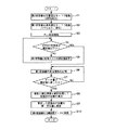
図3は、図1に示すタイミング信号生成装置における受信点の位置の算出を説明するフローチャートである。
(Calculation of receiving point position)
FIG. 3 is a flowchart for explaining the calculation of the position of the reception point in the timing signal generator shown in FIG.
タイミング信号生成装置1では、図3に示すように、まず、GPS制御部25がGPS受信機10b(第2受信機)を位置固定モードで起動する(ステップS1)。これにより、GPS受信機10bが1PPSの出力を開始する。
In the timing signal generator 1, as shown in FIG. 3, first, the
位置固定モードに設定する際に用いる受信点の位置情報は、受信点の正確な位置に対してある程度誤差があってもよく、例えば、ステップS1の前にあらかじめGPS受信機10aまたはGPS受信機10bで測位計算を行った結果を用いた位置情報や、記憶部60に記憶させておいた位置情報である。
The position information of the reception point used when setting the position fixing mode may have some error with respect to the accurate position of the reception point. For example, the
また、ステップS1の前に、GPS制御部25が、GPS受信機10bの仰角マスク(第2仰角マスク)の初期の設定値(初期値)を設定しておく。この仰角マスクの設定値は、受信点の設置環境等に応じて決められ、マルチパスの影響を受けない程度に設定され、具体的には、例えば、10度以上90度以下であることが好ましく、20度以上90度以下であることがより好ましく、30度以上90度以下であることがさらに好ましい。これにより、受信点の周囲に例えば建物、樹木等が存在するようなマルチパスが生じやすい環境下であっても、GPS受信機10bがマルチパスの影響を受け難くすることができる。これに対し、かかる設定値が小さすぎると、設置環境等によっては、GPS受信機10bがGPS受信機10aとともにマルチパスの影響を受けてしまい、位相比較器26の比較結果から、GPS受信機10aがマルチパスの影響を受けているか否かの判断が難しくなる。一方、かかる設定値が大きすぎると、GPS受信機10bが必要な数のGPS衛星2を捕捉するのに長時間を要してしまう。
In addition, before step S1, the
また、GPS受信機10bの仰角マスクの設定値は、変更可能であることが好ましい。これにより、GPS受信機10bの仰角マスクの初期値を設置環境に応じて最適化することができる。
Moreover, it is preferable that the setting value of the elevation mask of the
次に、GPS制御部25がGPS受信機10a(第1受信機)を通常測位モードで起動する(ステップS2)。これにより、GPS受信機10aが1PPSの出力および測位を開始する。
Next, the
ステップS2の前に、GPS制御部25が、GPS受信機10aの仰角マスクの初期の設定値(初期値)を設定しておく。この初期値は、受信点の設置環境等に応じて決められ、GPS受信機10bの仰角マスクの初期値よりも小さければよいが、衛星信号が受信可能な範囲内で、捕捉する4つ以上のGPS衛星2の位置ができるだけ互い遠くなることが好ましく、具体的には、例えば、45度未満であることが好ましく、5度以上30度であることがより好ましい。これにより、受信点の位置情報の生成に必要な4つ以上のGPS衛星2を比較的迅速に捕捉しつつ、捕捉した4つ以上のGPS衛星2の位置をできるだけ互いに遠くすることができる。
Prior to step S2, the
次に、原子発振器30が出力するクロック信号をGPS受信機10aからの1PPSに同期させる処理(位相比較器21、ループフィルター22、DSP23および分周器24によるPLL処理)を開始する(ステップS3)。このとき、位相比較器26の動作も開始する。
Next, processing for synchronizing the clock signal output from the
そして、位相比較器26の比較結果に基づいて、GPS受信機10aからの1PPSとGPS受信機10bからの1PPSとの位相差が規定値以下か否かを判断する(ステップS4)。
Based on the comparison result of the
ここで、GPS受信機10a、10bからの1PPSの位相がマルチパスの影響とは無関係に短期的に変動しても、この変動がマルチパスの有無の判断に影響を与えるのを防止する観点から、かかる判断に用いる位相差は、所定の時間長さごとの平均値(例えば移動平均を用いた値)であることが好ましい。また、この平均値を求める際の時間長さは、例えば、1分以上30分以下であることが好ましく、3分以上10分以下であることがより好ましい。これにより、マルチパスによる位相差情報の変動を的確に検出することができる。
Here, even if the phase of 1 PPS from the
また、ステップS4に用いる規定値は、40ns以下であることが好ましく、20ns以下であることがより好ましい。これにより、後述するようにステップS4、S5を繰り返すことで、GPS受信機10aの仰角マスクの設定値をマルチパスの影響のない(または少ない)値に調整することができる。
Further, the specified value used in step S4 is preferably 40 ns or less, and more preferably 20 ns or less. Thus, by repeating steps S4 and S5 as will be described later, the set value of the elevation mask of the
かかる位相差が規定値以下でない場合(ステップS4のNO)、GPS受信機10aの仰角マスクの設定値を変更する(ステップS5)。このステップS5では、GPS受信機10aの仰角マスクの設定値を所定角度だけ大きくする。すなわち、GPS受信機10aの仰角マスクの設定値をGPS受信機10bの仰角マスクの設定値に所定角度だけ大きくして近づける。この所定角度は、例えば、1度以上5度以下程度である。
If the phase difference is not less than the specified value (NO in step S4), the setting value of the elevation mask of the
このステップS5は、かかる位相差が規定値以下となるまで繰り返される。これにより、GPS受信機10aの仰角マスクの設定値は、GPS受信機10bの仰角マスクの設定値に対して所定角度ずつ段階的に大きくなって近づくこととなる。
This step S5 is repeated until the phase difference becomes a specified value or less. As a result, the setting value of the elevation mask of the
そして、かかる位相差が規定値以下となった場合(ステップS4のYES)、GPS受信機10aの測位情報を記憶部60に記憶する(ステップS6)。このステップS6は、GPS受信機10aの複数の測位計算結果である測位情報からなるデータの量が規定値に達するまで行われる(ステップS7のNO)。
And when this phase difference becomes below a regulation value (YES of step S4), the positioning information of the
記憶部60に記憶したデータの量が規定値に達したら(ステップS7のYES)、複数の測位計算結果(測位情報)を統計処理して受信点の位置を算出する(ステップS8)。そして、算出した受信点の位置をGPS受信機10aに設定し(ステップS9)、その後、GPS受信機10aを位置固定モードに変更する(ステップS10)。
When the amount of data stored in the
以上説明したようにして、位相比較器26の判断結果を用いて、GPS受信機10aの仰角マスクの設定値を調整し、その調整後のGPS受信機10aの測位計算結果を用いることで、受信点の位置を高精度に算出する。
As described above, the setting value of the elevation mask of the
以上説明したようなタイミング信号生成装置1によれば、GPS受信機10a、10bの仰角マスクの設定値を互いに異なる値に設定し、位相比較器26の比較結果に基づいて、GPS受信機10aがマルチパスの影響を受けているか否かを判断することができる。したがって、その判断結果を用いることで、GPS受信機10aの仰角マスク(第1仰角マスク)の設定値をマルチパスの影響を受けないように調整することができる。そして、その調整後のGPS受信機10aの測位計算結果を用いて受信点の位置を算出することで、マルチパスの影響を考慮した高精度な位置算出(真位置の算出)が可能となる。また、原子発振器30のクロック信号をGPS受信機10aからの1PPSに同期した高精度なタイミング信号として出力することができる。よって、受信環境が劣化しても、受信点の位置を高精度に算出して、高精度なタイミング信号を生成することができる。
According to the timing signal generator 1 as described above, the setting values of the elevation masks of the
本実施形態では、前述したように、GPS制御部25が、GPS受信機10aの仰角マスクの設定値をGPS受信機10bの仰角マスクの設定値よりも小さい値に設定し、位相比較器26の比較結果を用いて、GPS受信機10aの仰角マスクの設定値をGPS受信機10bの仰角マスクの設定値に近づく側の値に段階的に調整する。
In the present embodiment, as described above, the
GPS受信機10aの仰角マスクの設定値をGPS受信機10bの仰角マスクの設定値よりも小さい値に設定したとき、GPS受信機10aが、GPS受信機10bに比べて、捕捉可能な衛星信号の数が多くなり、マルチパスの影響を受けやすくなる。言い換えると、GPS受信機10bが、GPS受信機10aに比べて、捕捉可能な衛星信号の数が少なくなるものの、マルチパスの影響を受けづらくなる。したがって、マルチパスの影響を受けないようにGPS受信機10bの仰角マスクを大きく設定した状態でGPS受信機10aがマルチパスを受けた場合、GPS受信機10aのタイミング信号にはマルチパスの影響によりタイミングのズレが発生するが、GPS受信機10bにはタイミングのズレが発生しない。そのため、GPS受信機10aからの1PPSとGPS受信機10bからの1PPSとの位相差に基づいて、GPS受信機10aがマルチパスの影響を受けているか否かを判断することができる。したがって、GPS受信機10aの仰角マスクの設定値をGPS受信機10bの仰角マスクの設定値に近づく側の値に段階的に調整することで、GPS受信機10aの仰角マスクの設定値をマルチパスの影響を受けないように調整することができる。
When the setting value of the elevation mask of the
また、マルチパスの影響を考慮した高精度な受信点の位置算出を行う前であっても、GPS受信機10aの測位計算結果を用いてGPS受信機10aが1PPSを生成することができ、そのため、位置固定モードで設定する受信点の位置情報の入力誤差による影響を受けないで、高精度なタイミング信号の生成が可能である。
In addition, even before the highly accurate reception point position calculation considering the influence of multipath is performed, the
<第2実施形態>
次に、本発明の第2実施形態について説明する。
Second Embodiment
Next, a second embodiment of the present invention will be described.
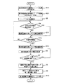
図4は、本発明の第2実施形態に係るタイミング信号生成装置における受信点の位置の算出を説明するフローチャートである。 FIG. 4 is a flowchart illustrating calculation of the position of the reception point in the timing signal generation device according to the second embodiment of the present invention.
本実施形態は、第1受信機および第2受信機の仰角マスクの設定方法が異なる以外は、前述した第1実施形態と同様である。 This embodiment is the same as the first embodiment described above except that the elevation angle mask setting methods of the first receiver and the second receiver are different.
なお、以下の説明では、第2実施形態に関し、前述した実施形態との相違点を中心に説明し、同様の事項に関してはその説明を省略する。また、図4において、前述した実施形態と同様の構成については、同一符号を付している。 In the following description, the second embodiment will be described with a focus on differences from the above-described embodiment, and description of similar matters will be omitted. In FIG. 4, the same reference numerals are given to the same configurations as those in the above-described embodiment.
本実施形態では、受信点の位置を算出する際には、図4に示すように、まず、GPS制御部25がGPS受信機10b(第2受信機)を位置固定モードで起動する(ステップS1A)。これにより、GPS受信機10bが1PPSの出力を開始する。
In this embodiment, when calculating the position of the reception point, as shown in FIG. 4, first, the
このステップS1Aの前に、GPS制御部25が、GPS受信機10bの仰角マスク(第2仰角マスク)の初期の設定値(初期値)を設定しておく。この初期値は、本実施形態では、前述した第1実施形態のGPS受信機10aの仰角マスクの初期値と同様の値に設定される。
Prior to step S1A, the
次に、GPS制御部25がGPS受信機10a(第1受信機)を通常測位モードで起動する(ステップS2A)。これにより、GPS受信機10aが1PPSの出力および測位を開始する。
Next, the
このステップS2Aの前に、GPS制御部25が、GPS受信機10aの仰角マスクの初期の設定値(初期値)を設定しておく。この初期値は、本実施形態では、前述した第1実施形態のGPS受信機10bの仰角マスクの初期値と同様の値に設定される。
Prior to step S2A, the
次に、前述した第1実施形態と同様、ステップS3、ステップS4を行う。そして、ステップS4において位相差が規定値以下でない場合(ステップS4のNO)、GPS制御部25がGPS受信機10bの仰角マスクの設定値を変更する(ステップS11)。このステップS11では、GPS受信機10bの仰角マスクの設定値を所定角度だけ大きくする。すなわち、GPS受信機10bの仰角マスクの設定値をGPS受信機10aの仰角マスクの設定値に所定角度だけ大きくして近づける。この所定角度は、例えば、1度以上5度以下程度である。
Next, step S3 and step S4 are performed as in the first embodiment described above. If the phase difference is not less than or equal to the specified value in step S4 (NO in step S4), the
このステップS11は、かかる位相差が規定値以下となり、かつ、所定時間経過するまで繰り返される(ステップS4のNOおよびステップS12のNO)。これにより、GPS受信機10bの仰角マスクの設定値は、GPS受信機10aの仰角マスクの設定値に対して所定角度ずつ段階的に大きくなって近づくこととなる。
This step S11 is repeated until the phase difference becomes equal to or less than the specified value and a predetermined time has elapsed (NO in step S4 and NO in step S12). As a result, the setting value of the elevation mask of the
そして、かかる位相差が規定値以下となり、かつ、所定時間経過した場合(ステップS4のYESおよびステップS12のYES)、GPS受信機10aの仰角マスクの設定値を調整する(ステップS13)。このステップS13では、前述したGPS受信機10bの調整後の仰角マスクの設定値に基づいて、GPS受信機10aの仰角マスクの設定値を調整する。より具体的には、GPS受信機10aの仰角マスクの設定値をGPS受信機10bの仰角マスクの設定値に一致または近づけることで調整する。これにより、マルチパスの影響を受けない範囲でGPS受信機10aの仰角マスクの設定値を大きくすることができる。
その後、前述した第1実施形態と同様、ステップS6〜S10を行う。
If the phase difference is equal to or less than the specified value and a predetermined time has elapsed (YES in step S4 and YES in step S12), the setting value of the elevation mask of the
Thereafter, steps S6 to S10 are performed as in the first embodiment described above.
以上説明したような第2実施形態では、GPS制御部25が、GPS受信機10aの仰角マスクの設定値をGPS受信機10bの仰角マスクの設定値よりも大きい値に設定し、位相比較器26の比較結果を用いて、GPS受信機10bの仰角マスクの設定値をGPS受信機10aの仰角マスクの設定値に近づく側の値に段階的に調整した後に、GPS受信機10bの仰角マスクの設定値に基づいてGPS受信機10aの仰角マスクの設定値を調整する。
In the second embodiment as described above, the
GPS受信機10aの仰角マスクの設定値をGPS受信機10bの仰角マスクの設定値よりも大きい値に設定したとき、GPS受信機10bが、GPS受信機10aに比べて、捕捉可能な衛星信号の数が多くなり、マルチパスの影響を受けやすくなる。言い換えると、このとき、GPS受信機10aが、GPS受信機10bに比べて、捕捉可能な衛星信号の数が少なくなるものの、マルチパスの影響を受けづらくなる。したがって、マルチパスの影響を受けないようにGPS受信機10aの仰角マスクを大きく設定した状態でGPS受信機10bがマルチパスを受けた場合、GPS受信機10bのタイミング信号にはマルチパスの影響によりタイミングのズレが発生するが、GPS受信機10aにはタイミングのズレが発生しない。そのため、GPS受信機10aからの1PPSとGPS受信機10bからの1PPSとの位相差に基づいて、GPS受信機10bがマルチパスの影響を受けているか否かを判断することができる。したがって、GPS受信機10bの仰角マスクの設定値をGPS受信機10aの仰角マスクの設定値に近づく側の値に段階的に調整することで、GPS受信機10bの仰角マスクの設定値をマルチパスの影響を受けないように調整することができる。そして、その調整後のGPS受信機10bの仰角マスクの設定値に基づいてGPS受信機10aの仰角マスクの設定値を調整することで、GPS受信機10aの仰角マスクの設定値もマルチパスの影響を受けないように調整することができる。
When the setting value of the elevation mask of the
また、仰角マスクの調整前において、マルチパスが生じやすい設置環境においても、マルチパスの影響を低減しつつ、高精度なタイミング信号の生成が可能となる。 In addition, even in an installation environment where multipath is likely to occur before adjustment of the elevation mask, it is possible to generate a highly accurate timing signal while reducing the effect of multipath.
以上説明したような第2実施形態によっても、受信環境が劣化しても、受信点の位置を高精度に算出して、高精度なタイミング信号を生成することができる。 According to the second embodiment as described above, even when the reception environment is deteriorated, the position of the reception point can be calculated with high accuracy and a highly accurate timing signal can be generated.
<第3実施形態>
次に、本発明の第3実施形態について説明する。
<Third Embodiment>
Next, a third embodiment of the present invention will be described.
図5は、本発明の第3実施形態に係るタイミング信号生成装置の概略構成を示す図である。図6は、図5に示すタイミング信号生成装置における受信点の位置の算出を説明するフローチャートである。 FIG. 5 is a diagram showing a schematic configuration of a timing signal generation device according to the third embodiment of the present invention. FIG. 6 is a flowchart for explaining the calculation of the position of the reception point in the timing signal generator shown in FIG.
本実施形態は、第1受信機および第2受信機と同期制御部との間に切換部(スイッチ)を設けた以外は、前述した第1実施形態と同様である。 The present embodiment is the same as the first embodiment described above except that a switching unit (switch) is provided between the first receiver and the second receiver and the synchronization control unit.
なお、以下の説明では、第3実施形態に関し、前述した実施形態との相違点を中心に説明し、同様の事項に関してはその説明を省略する。また、図5および図6において、前述した実施形態と同様の構成については、同一符号を付している。 In the following description, the third embodiment will be described with a focus on differences from the above-described embodiment, and description of similar matters will be omitted. 5 and 6, the same reference numerals are given to the same configurations as those in the above-described embodiment.
図5に示すタイミング信号生成装置1Bは、GPS受信機10と位相比較器21との間に設けられた切換部27を有する処理部20Bを備える。この切換部27は、同期制御部(位相比較器21、ループフィルター22、DSP23および分周器24)が原子発振器30からのクロック信号をGPS受信機10aからの1PPSに同期させる第1状態とGPS受信機10bからの1PPSに同期させる第2状態とを切り換え可能に構成されている。このような第1状態と第2状態とを適宜切り換えることで、マルチパスの影響を考慮した高精度な受信点の位置算出を行う前に、マルチパスの影響を低減しつつ、初期位置の入力誤差による影響を受けないで、高精度なタイミング信号の生成が可能である。
The timing signal generation device 1B illustrated in FIG. 5 includes a processing unit 20B having a switching
ここで、この切換部27の切り換えは、位相比較器26の比較結果に基づいてDSP23により行われる。すなわち、DSP23は、位相比較器26の比較結果に基づいて切換部27の切り換えを制御する「制御部」として機能する。これにより、位相比較器26の比較結果、すなわち、GPS受信機10aからの1PPSとGPS受信機10bからの1PPSとの位相差に基づいて、GPS受信機10aがマルチパスの影響を受けているか否かを判断し、その判断結果に基づいて、第1状態と第2状態とを切り換えることができる。
Here, the switching of the switching
このようなタイミング信号生成装置1Bにおいて、受信点の位置を算出する際には、図6に示すように、前述した第2実施形態と同様、ステップS1A、S2A、S3、S4を行う。 In such a timing signal generation device 1B, when calculating the position of the reception point, steps S1A, S2A, S3, and S4 are performed as in the second embodiment described above, as shown in FIG.
そして、ステップS4において位相差が規定値以下でない場合(ステップS4のNO)、前述した第2実施形態と同様にステップステップS11を行った後に、第1状態となるように、すなわち、GPS受信機10aからの1PPSが位相比較器21に入力されるように、切換部27を切り換える(ステップS14)。そして、ステップS12に移行する。
If the phase difference is not equal to or less than the specified value in step S4 (NO in step S4), after performing step step S11 in the same manner as in the second embodiment described above, the first state is obtained, that is, the GPS receiver. The switching
一方、規定値以下である場合(ステップS4のYES)、第2状態となるように、すなわち、GPS受信機10bからの1PPSが位相比較器21に入力されるように、切換部27を切り換える(ステップS15)。そして、ステップS12に移行する。
On the other hand, when the value is equal to or less than the specified value (YES in step S4), the switching
このようなGPS受信機10bの仰角マスクの設定値の変更(ステップS11)および切換部27の切り換え(ステップS14、S15)は、所定時間経過するまで行われる(ステップS12のNO)。
Such change of the setting value of the elevation mask of the
そして、所定時間経過した後(ステップS12のNO)、前述した第2実施形態と同様、ステップS13、S6〜10が行われる。 And after predetermined time passes (NO of step S12), step S13 and S6-10 are performed similarly to 2nd Embodiment mentioned above.
以上説明したような第3実施形態によっても、受信環境が劣化しても、受信点の位置を高精度に算出して、高精度なタイミング信号を生成することができる。 According to the third embodiment as described above, even when the reception environment is deteriorated, the position of the reception point can be calculated with high accuracy and a highly accurate timing signal can be generated.
2.電子機器
次に、本発明の電子機器の実施形態を説明する。
図7は、本発明の電子機器の実施形態を示すブロック図である。
2. Next, an embodiment of an electronic device of the present invention will be described.
FIG. 7 is a block diagram showing an embodiment of the electronic apparatus of the present invention.
図7に示す電子機器300は、タイミング信号生成装置310、CPU(Central Processing Unit)320、操作部330、ROM(Read Only Memory)340、RAM(Random Access Memory)350、通信部360および表示部370を含んで構成されている。
7 includes a
タイミング信号生成装置310は、例えば、前述したタイミング信号生成装置1であり、先に説明したように、衛星信号を受信して高精度のタイミング信号(1PPS)を生成し、外部に出力する。これにより、より低コストで信頼性の高い電子機器300を実現することができる。
The timing
CPU320は、ROM340等に記憶されているプログラムに従い、各種の計算処理や制御処理を行う。具体的には、CPU320は、タイミング信号生成装置310が出力するタイミング信号(1PPS)やクロック信号に同期して、計時処理、操作部330からの操作信号に応じた各種の処理、外部とデータ通信を行うために通信部360を制御する処理、表示部370に各種の情報を表示させるための表示信号を送信する処理等を行う。
The
操作部330は、操作キーやボタンスイッチ等により構成される入力装置であり、ユーザーによる操作に応じた操作信号をCPU320に出力する。
The
ROM340は、CPU320が各種の計算処理や制御処理を行うためのプログラムやデータ等を記憶している。
The
RAM350は、CPU320の作業領域として用いられ、ROM340から読み出されたプログラムやデータ、操作部330から入力されたデータ、CPU320が各種プログラムにしたがって実行した演算結果等を一時的に記憶する。
The
通信部360は、CPU320と外部装置との間のデータ通信を成立させるための各種制御を行う。
The
表示部370は、LCD(Liquid Crystal Display)等により構成される表示装置であり、CPU320から入力される表示信号に基づいて各種の情報を表示する。表示部370には操作部330として機能するタッチパネルが設けられていてもよい。
The
このような電子機器300としては種々の電子機器が考えられ、特に限定されないが、例えば、標準時刻との同期を実現する時刻管理用のサーバー(タイムサーバー)、タイムスタンプの発行等を行う時刻管理装置(タイムスタンプサーバー)、基地局等の周波数基準装置等が挙げられる。 Various electronic devices are conceivable as such an electronic device 300, and are not particularly limited. For example, a time management server that realizes synchronization with a standard time (time server), time management that issues time stamps, and the like Examples include devices (time stamp servers) and frequency reference devices such as base stations.
3.移動体
図8は、本発明の移動体の実施形態を示す図である。
3. FIG. 8 is a diagram showing an embodiment of the moving body of the present invention.
図8に示す移動体400は、タイミング信号生成装置410、カーナビゲーション装置420、コントローラー430、440、450、バッテリー460、バックアップ用バッテリー470を含んで構成されている。
A moving
タイミング信号生成装置410としては、前述したタイミング信号生成装置1を適用することができる。タイミング信号生成装置410は、例えば、移動体400が移動中は、通常測位モードでリアルタイムに測位計算を行って1PPS、クロック信号およびNMEAデータを出力する。また、タイミング信号生成装置410は、例えば、移動体400が停止中は、通常測位モードで複数回の測位計算を行った後、複数回の測位計算結果の最頻値または中央値を現在の位置情報として設定し、位置固定モードで1PPS、クロック信号およびNMEAデータを出力する。
As the timing signal generation device 410, the timing signal generation device 1 described above can be applied. For example, when the moving
カーナビゲーション装置420は、タイミング信号生成装置410が出力する1PPSやクロック信号に同期して、タイミング信号生成装置410が出力するNMEAデータを用いて、位置や時刻その他の各種の情報をディスプレイに表示する。
The
コントローラー430、440、450は、エンジンシステム、ブレーキシステム、キーレスエントリーシステム等の各種の制御を行う。コントローラー430、440、450は、タイミング信号生成装置410が出力するクロック信号に同期して各種の制御を行うようにしてもよい。
The
本実施形態の移動体400は、タイミング信号生成装置410を備えていることで、移動中も停止中も高い信頼性を確保することができる。
Since the moving
このような移動体400としては種々の移動体が考えられ、例えば、自動車(電気自動車も含む)、ジェット機やヘリコプター等の航空機、船舶、ロケット、人工衛星等が挙げられる。
As such a moving
以上、本発明のタイミング信号生成装置、電子機器および移動体について、図示の実施形態に基づいて説明したが、本発明は、これらに限定されるものではない。 As described above, the timing signal generation device, the electronic apparatus, and the moving body of the present invention have been described based on the illustrated embodiments, but the present invention is not limited to these.
また、本発明は、前述した実施形態の同様の機能を発揮する任意の構成のものに置換することができ、また、任意の構成を付加することもできる。 In addition, the present invention can be replaced with an arbitrary configuration that exhibits the same function as that of the above-described embodiment, and an arbitrary configuration can be added.
また、前述した実施形態では、GPSを利用したタイミング信号生成装置を例に挙げたが、GPS以外の全地球航法衛星システム(GNSS)、例えば、ガリレオ、GLONASS等を利用してもよい。 In the above-described embodiment, the timing signal generation device using GPS is taken as an example, but a global navigation satellite system (GNSS) other than GPS, for example, Galileo, GLONASS, or the like may be used.
1…タイミング信号生成装置、1B…タイミング信号生成装置、2…GPS衛星、10…GPS受信機、10a…GPS受信機(第1受信機)、10b…GPS受信機(第2受信機)、11…SAWフィルター、12…RF処理部、13…ベースバンド処理部、14…TCXO、20…処理部、20B…処理部、21…位相比較器、22…ループフィルター、23…DSP、24…分周器、25…GPS制御部(調整部)、26…位相比較器、27…切換部、30…原子発振器、40…温度センサー、50…GPSアンテナ、60…記憶部、121…PLL、122…LNA、123…ミキサー、124…IFアンプ、125…IFフィルター、126…ADC、131…DSP、132…CPU、133…SRAM、134…RTC、300…電子機器、310…タイミング信号生成装置、320…CPU、330…操作部、340…ROM、350…RAM、360…通信部、370…表示部、400…移動体、410…タイミング信号生成装置、420…カーナビゲーション装置、430…コントローラー、440…コントローラー、450…コントローラー、460…バッテリー、470…バックアップ用バッテリー、S1…ステップ、S2…ステップ、S3…ステップ、S4…ステップ、S5…ステップ、S6…ステップ、S7…ステップ、S8…ステップ、S9…ステップ、S10…ステップ、S11…ステップ、S12…ステップ、S13…ステップ、S14…ステップ、S15…ステップ、S1A…ステップ、S2A…ステップ
DESCRIPTION OF SYMBOLS 1 ... Timing signal generation apparatus, 1B ... Timing signal generation apparatus, 2 ... GPS satellite, 10 ... GPS receiver, 10a ... GPS receiver (1st receiver), 10b ... GPS receiver (2nd receiver), 11 ... SAW filter, 12 ... RF processing unit, 13 ... Baseband processing unit, 14 ... TCXO, 20 ... Processing unit, 20B ... Processing unit, 21 ... Phase comparator, 22 ... Loop filter, 23 ... DSP, 24 ...
Claims (9)
第2仰角マスクを用いて前記衛星信号を受信し、第2タイミング信号を出力する第2受信機と、
前記第1タイミング信号と前記第2タイミング信号との位相を比較する位相比較器と、
前記位相比較器の比較結果を用いて、前記第1仰角マスクおよび前記第2仰角マスクのうちの少なくとも一方の設定値を調整する調整部と、を備えることを特徴とするタイミング信号生成装置。 A first receiver that receives a satellite signal using a first elevation mask and outputs a first timing signal;
A second receiver for receiving the satellite signal using a second elevation mask and outputting a second timing signal;
A phase comparator that compares the phases of the first timing signal and the second timing signal;
A timing signal generation device comprising: an adjustment unit that adjusts a setting value of at least one of the first elevation angle mask and the second elevation angle mask using a comparison result of the phase comparator.
前記クロック信号を前記第1タイミング信号に同期させる同期制御部と、を備え、
前記調整部は、前記第1仰角マスクおよび前記第2仰角マスクを互いに異なる設定値に設定し、前記位相比較器の比較結果を用いて、前記第1仰角マスクの設定値を調整する請求項1に記載のタイミング信号生成装置。 An oscillator that outputs a clock signal;
A synchronization controller for synchronizing the clock signal with the first timing signal,
The adjustment unit sets the first elevation angle mask and the second elevation angle mask to different setting values, and adjusts the setting value of the first elevation angle mask using a comparison result of the phase comparator. The timing signal generator according to claim 1.
前記クロック信号を前記第1タイミング信号または前記第2タイミング信号に同期させる同期制御部と、
前記同期制御部が前記クロック信号を前記第1タイミング信号に同期させる第1状態と前記第2タイミング信号に同期させる第2状態とを切り換え可能な切換部と、を備える請求項1に記載のタイミング信号生成装置。 An oscillator that outputs a clock signal;
A synchronization control unit for synchronizing the clock signal with the first timing signal or the second timing signal;
2. The timing according to claim 1, further comprising: a switching unit capable of switching between a first state in which the synchronization control unit synchronizes the clock signal with the first timing signal and a second state in synchronization with the second timing signal. Signal generator.
前記調整部が前記第1仰角マスクの設定値を調整した後の前記第1受信機の測位計算結果を用いて、受信点の位置を算出する演算部を備える請求項1ないし6のいずれか1項に記載のタイミング信号生成装置。 The first receiver has a function of performing positioning calculation,
7. The calculation unit according to claim 1, further comprising: a calculation unit that calculates a position of a reception point using a positioning calculation result of the first receiver after the adjustment unit has adjusted a setting value of the first elevation mask. The timing signal generating device according to item.
Priority Applications (1)
| Application Number | Priority Date | Filing Date | Title |
|---|---|---|---|
| JP2016020139A JP2017138234A (en) | 2016-02-04 | 2016-02-04 | Timing signal generating device, electronic equipment, and mobile body |
Applications Claiming Priority (1)
| Application Number | Priority Date | Filing Date | Title |
|---|---|---|---|
| JP2016020139A JP2017138234A (en) | 2016-02-04 | 2016-02-04 | Timing signal generating device, electronic equipment, and mobile body |
Publications (1)
| Publication Number | Publication Date |
|---|---|
| JP2017138234A true JP2017138234A (en) | 2017-08-10 |
Family
ID=59566753
Family Applications (1)
| Application Number | Title | Priority Date | Filing Date |
|---|---|---|---|
| JP2016020139A Pending JP2017138234A (en) | 2016-02-04 | 2016-02-04 | Timing signal generating device, electronic equipment, and mobile body |
Country Status (1)
| Country | Link |
|---|---|
| JP (1) | JP2017138234A (en) |
-
2016
- 2016-02-04 JP JP2016020139A patent/JP2017138234A/en active Pending
Similar Documents
| Publication | Publication Date | Title |
|---|---|---|
| US9952562B2 (en) | Timing signal generating device, electronic apparatus, moving object, method of generating timing signals, and method of controlling satellite signal receiver | |
| US10187074B2 (en) | Timing signal generation device, electronic device, and moving object | |
| US10700690B2 (en) | Timing signal generation device, electronic device, and moving object | |
| US10782415B2 (en) | Timing signal generation device and electronic apparatus | |
| JP6379549B2 (en) | Timing signal generating apparatus and electronic device | |
| JP6201585B2 (en) | Timing signal generating device, electronic device, and moving object | |
| US10222482B2 (en) | Position information generation device, timing signal generation device, electronic apparatus, and moving object | |
| JP6627489B2 (en) | Timing signal generator and electronic equipment | |
| US10168434B2 (en) | Reference signal generation device, electronic device, moving object, data communication device, and terrestrial digital communication network | |
| US9762341B2 (en) | Time synchronization system | |
| US20180246216A1 (en) | Timing signal output device, and electronic apparatus | |
| JP2017216612A (en) | Timing signal generation device, electronic apparatus, and mobile body | |
| JP6264973B2 (en) | Timing signal generating device, electronic device, and moving object | |
| US10383078B2 (en) | Timing signal output device and electronic device | |
| JP2017138197A (en) | Timing signal generating device, electronic equipment, and mobile body | |
| JP2017138234A (en) | Timing signal generating device, electronic equipment, and mobile body | |
| JP2016195347A (en) | Timing signal generator, electronic apparatus and moving body | |
| JP6485501B2 (en) | Signal generation method | |
| JP6753068B2 (en) | Timing signal generators and electronic devices | |
| JP6361354B2 (en) | Positioning device, timing signal generating device, electronic device, and moving object | |
| JP2017059971A (en) | Timing signal generator, electronic apparatus and movable body |