JP6583195B2 - Air conditioner for vehicles - Google Patents
Air conditioner for vehicles Download PDFInfo
- Publication number
- JP6583195B2 JP6583195B2 JP2016174240A JP2016174240A JP6583195B2 JP 6583195 B2 JP6583195 B2 JP 6583195B2 JP 2016174240 A JP2016174240 A JP 2016174240A JP 2016174240 A JP2016174240 A JP 2016174240A JP 6583195 B2 JP6583195 B2 JP 6583195B2
- Authority
- JP
- Japan
- Prior art keywords
- air
- temperature
- vehicle
- unit
- control
- Prior art date
- Legal status (The legal status is an assumption and is not a legal conclusion. Google has not performed a legal analysis and makes no representation as to the accuracy of the status listed.)
- Active
Links
- 238000004378 air conditioning Methods 0.000 claims description 162
- 230000008859 change Effects 0.000 claims description 78
- 238000007664 blowing Methods 0.000 claims description 34
- 238000001514 detection method Methods 0.000 claims description 23
- 239000003507 refrigerant Substances 0.000 description 31
- 238000001816 cooling Methods 0.000 description 30
- 238000000034 method Methods 0.000 description 21
- 238000005057 refrigeration Methods 0.000 description 21
- 230000008569 process Effects 0.000 description 18
- 238000010438 heat treatment Methods 0.000 description 8
- 239000007788 liquid Substances 0.000 description 5
- 230000005855 radiation Effects 0.000 description 5
- 230000006872 improvement Effects 0.000 description 4
- 238000012545 processing Methods 0.000 description 4
- 230000035807 sensation Effects 0.000 description 4
- 238000009423 ventilation Methods 0.000 description 4
- 238000010521 absorption reaction Methods 0.000 description 3
- 239000000498 cooling water Substances 0.000 description 3
- 230000006870 function Effects 0.000 description 3
- 238000011144 upstream manufacturing Methods 0.000 description 3
- CURLTUGMZLYLDI-UHFFFAOYSA-N Carbon dioxide Chemical compound O=C=O CURLTUGMZLYLDI-UHFFFAOYSA-N 0.000 description 2
- 206010016334 Feeling hot Diseases 0.000 description 2
- KYKAJFCTULSVSH-UHFFFAOYSA-N chloro(fluoro)methane Chemical compound F[C]Cl KYKAJFCTULSVSH-UHFFFAOYSA-N 0.000 description 2
- 230000001143 conditioned effect Effects 0.000 description 2
- 230000006866 deterioration Effects 0.000 description 2
- 238000010586 diagram Methods 0.000 description 2
- 230000000694 effects Effects 0.000 description 2
- 239000007791 liquid phase Substances 0.000 description 2
- 239000011159 matrix material Substances 0.000 description 2
- 230000007246 mechanism Effects 0.000 description 2
- 239000002699 waste material Substances 0.000 description 2
- XLYOFNOQVPJJNP-UHFFFAOYSA-N water Substances O XLYOFNOQVPJJNP-UHFFFAOYSA-N 0.000 description 2
- 239000004215 Carbon black (E152) Substances 0.000 description 1
- 239000004743 Polypropylene Substances 0.000 description 1
- 238000009529 body temperature measurement Methods 0.000 description 1
- 229910002092 carbon dioxide Inorganic materials 0.000 description 1
- 239000001569 carbon dioxide Substances 0.000 description 1
- 230000006835 compression Effects 0.000 description 1
- 238000007906 compression Methods 0.000 description 1
- 239000002826 coolant Substances 0.000 description 1
- 238000012937 correction Methods 0.000 description 1
- 230000006837 decompression Effects 0.000 description 1
- 238000007791 dehumidification Methods 0.000 description 1
- 230000005611 electricity Effects 0.000 description 1
- 229930195733 hydrocarbon Natural products 0.000 description 1
- 150000002430 hydrocarbons Chemical class 0.000 description 1
- 238000012986 modification Methods 0.000 description 1
- 230000004048 modification Effects 0.000 description 1
- 230000002093 peripheral effect Effects 0.000 description 1
- -1 polypropylene Polymers 0.000 description 1
- 229920001155 polypropylene Polymers 0.000 description 1
- 239000011347 resin Substances 0.000 description 1
- 229920005989 resin Polymers 0.000 description 1
- 238000000926 separation method Methods 0.000 description 1
Images


Classifications
-
- B—PERFORMING OPERATIONS; TRANSPORTING
- B60—VEHICLES IN GENERAL
- B60H—ARRANGEMENTS OF HEATING, COOLING, VENTILATING OR OTHER AIR-TREATING DEVICES SPECIALLY ADAPTED FOR PASSENGER OR GOODS SPACES OF VEHICLES
- B60H1/00—Heating, cooling or ventilating [HVAC] devices
- B60H1/00642—Control systems or circuits; Control members or indication devices for heating, cooling or ventilating devices
- B60H1/00735—Control systems or circuits characterised by their input, i.e. by the detection, measurement or calculation of particular conditions, e.g. signal treatment, dynamic models
- B60H1/00742—Control systems or circuits characterised by their input, i.e. by the detection, measurement or calculation of particular conditions, e.g. signal treatment, dynamic models by detection of the vehicle occupants' presence; by detection of conditions relating to the body of occupants, e.g. using radiant heat detectors
-
- B—PERFORMING OPERATIONS; TRANSPORTING
- B60—VEHICLES IN GENERAL
- B60H—ARRANGEMENTS OF HEATING, COOLING, VENTILATING OR OTHER AIR-TREATING DEVICES SPECIALLY ADAPTED FOR PASSENGER OR GOODS SPACES OF VEHICLES
- B60H1/00—Heating, cooling or ventilating [HVAC] devices
- B60H1/00642—Control systems or circuits; Control members or indication devices for heating, cooling or ventilating devices
- B60H1/00814—Control systems or circuits characterised by their output, for controlling particular components of the heating, cooling or ventilating installation
- B60H1/00878—Control systems or circuits characterised by their output, for controlling particular components of the heating, cooling or ventilating installation the components being temperature regulating devices
-
- B—PERFORMING OPERATIONS; TRANSPORTING
- B60—VEHICLES IN GENERAL
- B60H—ARRANGEMENTS OF HEATING, COOLING, VENTILATING OR OTHER AIR-TREATING DEVICES SPECIALLY ADAPTED FOR PASSENGER OR GOODS SPACES OF VEHICLES
- B60H1/00—Heating, cooling or ventilating [HVAC] devices
-
- B—PERFORMING OPERATIONS; TRANSPORTING
- B60—VEHICLES IN GENERAL
- B60H—ARRANGEMENTS OF HEATING, COOLING, VENTILATING OR OTHER AIR-TREATING DEVICES SPECIALLY ADAPTED FOR PASSENGER OR GOODS SPACES OF VEHICLES
- B60H1/00—Heating, cooling or ventilating [HVAC] devices
- B60H1/00007—Combined heating, ventilating, or cooling devices
- B60H1/00021—Air flow details of HVAC devices
- B60H1/00064—Air flow details of HVAC devices for sending air streams of different temperatures into the passenger compartment
-
- B—PERFORMING OPERATIONS; TRANSPORTING
- B60—VEHICLES IN GENERAL
- B60H—ARRANGEMENTS OF HEATING, COOLING, VENTILATING OR OTHER AIR-TREATING DEVICES SPECIALLY ADAPTED FOR PASSENGER OR GOODS SPACES OF VEHICLES
- B60H1/00—Heating, cooling or ventilating [HVAC] devices
- B60H1/00642—Control systems or circuits; Control members or indication devices for heating, cooling or ventilating devices
- B60H1/00735—Control systems or circuits characterised by their input, i.e. by the detection, measurement or calculation of particular conditions, e.g. signal treatment, dynamic models
- B60H1/00764—Control systems or circuits characterised by their input, i.e. by the detection, measurement or calculation of particular conditions, e.g. signal treatment, dynamic models the input being a vehicle driving condition, e.g. speed
- B60H1/00778—Control systems or circuits characterised by their input, i.e. by the detection, measurement or calculation of particular conditions, e.g. signal treatment, dynamic models the input being a vehicle driving condition, e.g. speed the input being a stationary vehicle position, e.g. parking or stopping
-
- B—PERFORMING OPERATIONS; TRANSPORTING
- B60—VEHICLES IN GENERAL
- B60H—ARRANGEMENTS OF HEATING, COOLING, VENTILATING OR OTHER AIR-TREATING DEVICES SPECIALLY ADAPTED FOR PASSENGER OR GOODS SPACES OF VEHICLES
- B60H1/00—Heating, cooling or ventilating [HVAC] devices
- B60H1/00642—Control systems or circuits; Control members or indication devices for heating, cooling or ventilating devices
- B60H1/00814—Control systems or circuits characterised by their output, for controlling particular components of the heating, cooling or ventilating installation
- B60H1/00821—Control systems or circuits characterised by their output, for controlling particular components of the heating, cooling or ventilating installation the components being ventilating, air admitting or air distributing devices
- B60H1/00828—Ventilators, e.g. speed control
-
- B—PERFORMING OPERATIONS; TRANSPORTING
- B60—VEHICLES IN GENERAL
- B60H—ARRANGEMENTS OF HEATING, COOLING, VENTILATING OR OTHER AIR-TREATING DEVICES SPECIALLY ADAPTED FOR PASSENGER OR GOODS SPACES OF VEHICLES
- B60H1/00—Heating, cooling or ventilating [HVAC] devices
- B60H1/00642—Control systems or circuits; Control members or indication devices for heating, cooling or ventilating devices
- B60H1/00964—Control systems or circuits characterised by including features for automatic and non-automatic control, e.g. for changing from automatic to manual control
-
- B—PERFORMING OPERATIONS; TRANSPORTING
- B60—VEHICLES IN GENERAL
- B60H—ARRANGEMENTS OF HEATING, COOLING, VENTILATING OR OTHER AIR-TREATING DEVICES SPECIALLY ADAPTED FOR PASSENGER OR GOODS SPACES OF VEHICLES
- B60H1/00—Heating, cooling or ventilating [HVAC] devices
- B60H1/32—Cooling devices
-
- B—PERFORMING OPERATIONS; TRANSPORTING
- B60—VEHICLES IN GENERAL
- B60H—ARRANGEMENTS OF HEATING, COOLING, VENTILATING OR OTHER AIR-TREATING DEVICES SPECIALLY ADAPTED FOR PASSENGER OR GOODS SPACES OF VEHICLES
- B60H1/00—Heating, cooling or ventilating [HVAC] devices
- B60H1/32—Cooling devices
- B60H1/3204—Cooling devices using compression
- B60H1/3205—Control means therefor
-
- B—PERFORMING OPERATIONS; TRANSPORTING
- B60—VEHICLES IN GENERAL
- B60H—ARRANGEMENTS OF HEATING, COOLING, VENTILATING OR OTHER AIR-TREATING DEVICES SPECIALLY ADAPTED FOR PASSENGER OR GOODS SPACES OF VEHICLES
- B60H1/00—Heating, cooling or ventilating [HVAC] devices
- B60H1/32—Cooling devices
- B60H1/3204—Cooling devices using compression
- B60H1/3227—Cooling devices using compression characterised by the arrangement or the type of heat exchanger, e.g. condenser, evaporator
Landscapes
- Physics & Mathematics (AREA)
- Thermal Sciences (AREA)
- Engineering & Computer Science (AREA)
- Mechanical Engineering (AREA)
- Air-Conditioning For Vehicles (AREA)
Description
本発明は、車室内の温度に応じて車室内の空調を制御する車両用空調装置に関する。 The present invention relates to a vehicle air conditioner that controls air conditioning in a vehicle interior in accordance with the temperature in the vehicle interior.
従来、車両用空調装置は、車両の車室内における乗員の快適性を高める為に、車両に設けられている。このような車両用空調装置として、車室内の内気温に応じて、冷暖房等の空調を自動的に制御するものが知られている。 Conventionally, a vehicle air conditioner is provided in a vehicle in order to enhance the comfort of passengers in the vehicle interior of the vehicle. As such a vehicle air conditioner, one that automatically controls air conditioning such as cooling and heating according to the inside air temperature in the passenger compartment is known.
一方、車室には、ウィンドウ、ドアやサンルーフ等の開口が設けられている。これらのウィンドウ等は、車両用空調装置による車室内の空調が行われている場合であっても、換気等を目的として開かれる場合がある。 On the other hand, the vehicle compartment is provided with openings such as windows, doors and sunroofs. These windows and the like may be opened for the purpose of ventilation or the like even when the vehicle air conditioning is performed by the vehicle air conditioner.
この場合、ウィンドウ等の開口部を介して、車室外の外気が車室内に流入する為、車室に対する熱負荷や車室内の温度や等は大きく変動することになる。即ち、車室内の乗員の温熱感は、開口部を介した外気の流入によって大きな影響を受ける。 In this case, since the outside air outside the passenger compartment flows into the passenger compartment through the opening such as a window, the thermal load on the passenger compartment, the temperature in the passenger compartment, and the like greatly vary. That is, the thermal sensation of the passenger in the passenger compartment is greatly affected by the inflow of outside air through the opening.
この点に鑑みてなされた技術として、特許文献1に記載された技術が知られている。特許文献1に記載された車両用空調装置は、ウィンドウが開いたことを検知すると、車室内に対する外気の流入の影響(即ち、車室内に対する熱負荷の変動)を緩和する為に、より大きな消費動力で空調制御を行うように構成されている。
As a technique made in view of this point, a technique described in
例えば、真夏のように外気温が高く、車室内を冷房している場合において、ウィンドウが開いたことを検知すると、この車両用空調装置は、外気の流入による内気温の上昇を緩和する為に、より大きな消費動力で冷房を行うように構成されている。 For example, when the outside air temperature is high as in midsummer and the passenger compartment is air-conditioned, if the opening of the window is detected, the vehicle air conditioner It is configured to perform cooling with greater power consumption.
しかしながら、特許文献1に記載された車両用空調装置においても、外気の流入による車室内に対する熱負荷の変化が激しすぎると、車両用空調装置よる空調能力を超えてしまう場合がある。
However, even in the vehicle air conditioner described in
例えば、車室内を冷房している場合に、高温の外気が大量に車室内へ流入すると、車両用空調装置が最大能力で冷房していても、車室内を冷やすことができない場合が起こりうる。この場合、車両用空調装置の最大能力で冷房しているにも関わらず、乗員の温熱感を悪化させてしまう。 For example, when the vehicle interior is being cooled, if a large amount of high-temperature outside air flows into the vehicle interior, there may occur a case where the vehicle interior cannot be cooled even if the vehicle air conditioner is cooling at the maximum capacity. In this case, the passenger's thermal sensation is deteriorated in spite of cooling with the maximum capacity of the vehicle air conditioner.
このような場合、車室内の内気温に応じた空調制御に伴って、車両用空調制御装置の消費動力を増大させているにも拘らず、乗員の快適性が悪化してしまうのであれば、車両用空調装置の増大させた消費動力は無駄ということになる。従って、特許文献1に記載された車両用空調装置は、上述のような場合における消費動力の無駄という点で改善の余地を有している。
In such a case, if the passenger's comfort deteriorates despite increasing the power consumption of the vehicle air conditioning control device in accordance with the air conditioning control according to the inside air temperature in the passenger compartment, The increased power consumption of the vehicle air conditioner is wasted. Therefore, the vehicle air conditioner described in
本発明は、上述した点に鑑み、車室内の温度に応じて車室内の空調を制御する車両用空調装置に関し、車室内に外気が流入する場合における消費動力の増大を抑制可能な車両用空調装置を提供することを目的とする。 The present invention relates to a vehicle air conditioner that controls air conditioning in a vehicle interior in accordance with the temperature in the vehicle interior in view of the above-described points, and relates to a vehicle air conditioner that can suppress an increase in power consumption when outside air flows into the vehicle interior. An object is to provide an apparatus.
前記目的を達成するため、請求項1に記載の車両用空調装置は、
車室内外を連通すると共に開閉可能に設けられた開口部を有する車両に適用される車両用空調装置であって、
車室内の内気温を検出する内気温検出部(32)と、
車室内における空気の温度を調整する温度調整部(10、11)と、車室内に空気を送風する送風部(1、8)とを備え、車室内の空調を行う為の室内空調部(1、10)と、
内気温検出部によって検出された内気温に応じて、室内空調部の作動を自動的に変更するオート制御を行う空調制御部(30)と、
開口部が開いていることを示す開信号を検出する開信号検出部(30、45)と、
車室内における熱負荷の変化がオート制御による空調能力を超えるか否かを判定する熱負荷判定部(30)と、を有し、
空調制御部(30)は、開信号が検出され、且つ、車室内に対する熱負荷の変化がオート制御による空調能力を超えると判定された場合に、内気温(Tr)に関わらず、室内空調部における温度調整部と送風部の少なくとも一方による消費動力の上昇を抑制する省動力制御を実行し、
前記省動力制御の実行に際し、前記室内空調部における前記温度調整部(10、11)の消費動力を、前記内気温(Tr)に関わらず維持する。
In order to achieve the object, an air conditioner for a vehicle according to
A vehicle air conditioner that is applied to a vehicle that communicates between the interior and exterior of the vehicle and has an opening that can be opened and closed,
An internal air temperature detector (32) for detecting the internal air temperature in the passenger compartment;
An air conditioner (1 and 8) for adjusting the temperature of the air in the passenger compartment and an air blower (1 and 8) for blowing air into the passenger compartment, and for air conditioning the passenger compartment (1 10)
An air-conditioning control unit (30) that performs automatic control to automatically change the operation of the indoor air-conditioning unit according to the internal air temperature detected by the internal air-temperature detecting unit;
An open signal detector (30, 45) for detecting an open signal indicating that the opening is open;
A thermal load determination unit (30) for determining whether or not the change in the thermal load in the passenger compartment exceeds the air conditioning capability by automatic control,
The air conditioning control unit (30) detects the open signal and determines that the change in the thermal load on the passenger compartment exceeds the air conditioning capability by the automatic control, regardless of the internal air temperature (Tr). The power saving control for suppressing the increase in power consumption by at least one of the temperature adjusting unit and the air blowing unit in
When executing the power saving control, the power consumption of the temperature adjusting unit (10, 11) in the indoor air conditioning unit is maintained regardless of the inside air temperature (Tr) .
この車両用空調装置によれば、通常の場合、空調制御部によって室内空調部のオート制御が行われる為、開口部を有する車両の車室内に対して、内気温検出部によって検出された内気温に応じた快適な空調を実現することができる。 According to this vehicle air conditioner, since the air conditioning control unit normally performs automatic control of the indoor air conditioning unit, the inside air temperature detected by the inside air temperature detecting unit with respect to the vehicle interior of the vehicle having an opening is provided. Comfortable air conditioning according to the can be realized.
そして、開信号検出部と熱負荷判定部を有している為、車両用空調装置は、開口部が開き、車室内に対する熱負荷の変化がオート制御による空調能力を超える状態にあることを判定することができる。 And since it has the open signal detection part and the thermal load determination part, the vehicle air conditioner determines that the opening is open and the change in the thermal load on the passenger compartment exceeds the air conditioning capability by automatic control. can do.
開口部が開き、車室内に対する熱負荷の変化がオート制御による空調能力を超える状態では、室内空調部により消費動力を増大させて、オート制御時における空調能力を最大限発揮させた場合であっても、車室内における乗員の温感が悪化していく状態である。 In a state where the opening is open and the change in the heat load on the passenger compartment exceeds the air conditioning capacity by auto control, the power consumption is increased by the indoor air conditioner to maximize the air conditioning capacity during auto control. However, the warmth of the passenger in the passenger compartment is getting worse.
本発明に係る車両用空調装置によれば、開信号が検出され、且つ、前記車室内に対する熱負荷の変化がオート制御による空調能力を超えると判定された場合には、省動力制御が行われる為、開口部の開放に伴って車室内における熱負荷が増大したとしても、増大した熱負荷に対応する為に室内空調部の消費動力が増大することはない。 According to the vehicle air conditioner of the present invention, when an open signal is detected and it is determined that the change in the heat load on the vehicle interior exceeds the air conditioning capability by the automatic control, the power saving control is performed. Therefore, even if the thermal load in the passenger compartment increases with the opening of the opening, the power consumption of the indoor air conditioning unit does not increase to cope with the increased thermal load.
即ち、車両用空調装置は、車室内の温度に応じて車室内の空調を制御するオート制御を実行している場合に、車室内に外気が流入する場合における消費動力の増大を抑制することができる。 In other words, the vehicle air conditioner can suppress an increase in power consumption when outside air flows into the vehicle interior when performing automatic control for controlling the air conditioning of the vehicle interior according to the temperature in the vehicle interior. it can.
なお、この欄および特許請求の範囲で記載した各手段の括弧内の符号は、後述する実施態に記載の具体的手段との対応関係を示すものである。 In addition, the code | symbol in the bracket | parenthesis of each means described in this column and the claim shows the correspondence with the specific means as described in the embodiment described later.
以下、実施形態について図に基づいて説明する。以下の各実施形態相互において、互いに同一もしくは均等である部分には、図中、同一符号を付してある。 Hereinafter, embodiments will be described with reference to the drawings. In the following embodiments, the same or equivalent parts are denoted by the same reference numerals in the drawings.
(第1実施形態)
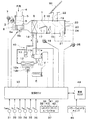
本発明に係る車両用空調装置を、車室内空間を適切な温度に調整するために用いられる車両用空調装置に適用した実施形態(第1実施形態)に基づいて、図面を参照しつつ詳細に説明する。図1は第1実施形態に係る車両用空調装置の全体構成の概要を示している。
(First embodiment)
Based on an embodiment (first embodiment) in which a vehicle air-conditioning apparatus according to the present invention is applied to a vehicle air-conditioning apparatus used to adjust a vehicle interior space to an appropriate temperature, with reference to the drawings. explain. FIG. 1 shows an overview of the overall configuration of the vehicle air conditioner according to the first embodiment.
尚、第1実施形態に係る車両用空調装置は、車室内空間を適切な温度に調整する為に、車両エンジンEで駆動する車両に搭載されている。第1実施形態に係る車両には、車室の両側面を構成するドアに、電気又は空気による動力で開閉可能な窓(以下、パワーウィンドウ)が配置されている。このパワーウィンドウは、後述するパワーウィンドウスイッチ45の操作によって任意に開閉可能に構成されている。即ち、パワーウィンドウは本発明における開口部の一例である。
The vehicle air conditioner according to the first embodiment is mounted on a vehicle driven by the vehicle engine E in order to adjust the vehicle interior space to an appropriate temperature. In the vehicle according to the first embodiment, windows that can be opened and closed by power by electricity or air (hereinafter, power windows) are arranged on doors that constitute both side surfaces of the passenger compartment. This power window is configured to be arbitrarily opened and closed by operating a
図1に示すように、第1実施形態に係る車両用空調装置は、室内空調ユニット1と、冷凍サイクル装置10と、空調制御装置30とを有している。
As shown in FIG. 1, the vehicle air conditioner according to the first embodiment includes an indoor
室内空調ユニット1は、車両における車室内最前部の計器盤(例えば、インストルメントパネル)内側に配置されている。
The indoor
室内空調ユニット1は、その外殻を形成するケーシング2内に、内外気切替箱5、室内送風機8、ヒータコア15、バイパス通路16及びエアミックスドア17等を収容している。
The indoor
そして、ケーシング2は、車室内送風空気の空気通路を形成している。このケーシング2は、一定の弾性を有し、強度的にも優れた樹脂(例えば、ポリプロピレン)にて成形されている。
And the
このケーシング2の空気通路の最上流部には、内外気切替箱5が配置されている。内外気切替箱5は、車室内と連通する内気導入口3と、車室外と連通する外気導入口4と、内外気切替ドア6及びサーボモータ7を有している。
An inside / outside air switching box 5 is arranged in the most upstream part of the air passage of the
内外気切替ドア6は、内外気切替箱5の内部において回転自在に配置されており、サーボモータ7によって駆動される。内外気切替箱5は、内外気切替ドア6の駆動制御を行うことで、内気導入口3より内気(車室内空気)を導入する内気モードと、外気導入口4より外気(車室外空気)を導入する外気モードと、内気と外気を同時に導入する半内気モードとを切り替えることができる。
The inside / outside
そして、内外気切替箱5の下流側には、電動式の室内送風機8が配置されている。室内送風機8は、遠心多翼ファン8aをモータ8bにより駆動し、車室内に向かって空気を送風するように構成されている。
An electric
室内送風機8の下流側には、冷凍サイクル装置10を構成する蒸発器9が配置されている。蒸発器9に流入した低圧の冷媒は、室内送風機8によって送風された送風空気から吸熱して蒸発する為、蒸発器9は、室内送風機8から送風された送風空気を冷却することができる。
An evaporator 9 constituting the
冷凍サイクル装置10は、蒸気圧縮式冷凍機として構成されており、蒸発器9に加え、圧縮機11、凝縮器12、気液分離器13、膨張弁14を有している。この冷凍サイクル装置10では、冷媒としてフロン系冷媒を用いている。即ち、この冷凍サイクル装置10は、高圧側冷媒圧力が冷媒の臨界圧力を超えない亜臨界冷凍サイクルを構成している。
The
圧縮機11は、冷凍サイクル装置10の冷媒を吸入して圧縮して吐出する。そして、圧縮機11は、電磁クラッチ11a、プーリ及びベルトVを介して伝達される車両エンジンEの回転動力により駆動される。そして、圧縮機11は、外部からの制御信号により吐出容量を連続的に可変制御できる可変容量型圧縮機である。
The compressor 11 sucks and compresses the refrigerant of the
具体的には、圧縮機11は、空調制御装置30から出力される制御電流によって開度が変位する電磁式容量制御弁11bを有して構成されている。この圧縮機11は、電磁式容量制御弁11bの開度を調整して、圧縮機11における制御圧を制御することで、ピストンのストロークを変化させる。これにより、圧縮機11は、吐出容量を略0%〜100%の範囲で連続的に変化させることができる。
Specifically, the compressor 11 includes an electromagnetic
凝縮器12は、圧縮機11から吐出された冷媒と室外送風機である冷却ファン12aから送風された車室外空気(即ち、外気)とを熱交換させて冷媒を凝縮させる。凝縮器12は、いわゆる凝縮器として機能する。
The
そして、冷却ファン12aは、電動式送風機であり、空調制御装置30からモータ12bに入力される制御電圧によって稼働率(即ち、回転数)が制御される。即ち、冷却ファン12aによる送風空気量は、空調制御装置30によって適宜制御することができる。
The cooling
気液分離器13は、凝縮器12にて凝縮された冷媒を気液分離して余剰冷媒を蓄えると共に、液相冷媒のみを下流側に流すレシーバである。
The gas-
膨張弁14は、気液分離器13で分離された液相冷媒を減圧膨張させる減圧部であり、弁体と電動アクチュエータとを備え、電気式の可変絞り機構を有して構成されている。弁体は、冷媒通路の通路開度(換言すれば絞り開度)を変更可能に構成されている。電動アクチュエータは、弁体の絞り開度を変化させるステッピングモータを有している。
The
従って、膨張弁14は、空調制御装置30から出力される制御信号によって、その作動が制御される。つまり、膨張弁14によれば、空調制御装置30からの制御信号に基づいて、冷媒を等エンタルピ的に減圧すると共に、圧縮機11に吸入される冷媒の過熱度が所定値となるように絞り開度を制御することが可能となる。
Therefore, the operation of the
冷凍サイクル装置10においては、膨張弁14にて減圧膨張された冷媒は、蒸発器9に流入して蒸発し、その後、再び圧縮機11に流入する。このように、圧縮機11→凝縮器12→気液分離器13→膨張弁14→蒸発器9→圧縮機11の順で冷媒が循環する冷凍サイクルが構成される。尚、上述した冷凍サイクルの構成装置(蒸発器9、圧縮機11〜膨張弁14)の間は、それぞれ冷媒配管によって接続されている。
In the
図1に示すように、室内空調ユニット1における蒸発器9の下流側には、ヒータコア15が配置されている。ヒータコア15は、図示しないエンジン冷却水回路を循環する車両エンジンEの冷却水を熱源として用い、蒸発器9通過後の空気(冷風)を加熱する。
As shown in FIG. 1, a
そして、ヒータコア15の側方には、バイパス通路16が形成されている。バイパス通路16は、蒸発器9を通過した空気を、ヒータコア15を迂回させてヒータコア15の空気流れ下流側へ導く。
A
蒸発器9に対する空気流れ下流側であって、ヒータコア15及びバイパス通路16に対して空気流れ上流側には、エアミックスドア17が回転自在に配置されている。エアミックスドア17は、サーボモータ18により駆動される。この車両用空調装置では、空調制御装置30によりサーボモータ18の作動制御を行うことで、エアミックスドア17の回転位置(開度)を連続的に調整可能になっている。
An
そして、車両用空調装置では、エアミックスドア17の開度により、ヒータコア15を通る空気量(温風量)と、バイパス通路16を通過してヒータコア15をバイパスする空気量(冷風量)との割合を調節することができる。即ち、車両用空調装置は、車室内に吹き出す空気の温度を調整することができる。
In the vehicle air conditioner, the ratio of the amount of air passing through the heater core 15 (warm air amount) and the amount of air passing through the
更に、ケーシング2の送風空気流れ最下流部には、デフロスタ吹出口19と、フェイス吹出口20と、フット吹出口21が配置されている。これらの吹出口は、エアミックスドア17により温度調整された空調風を、空調対象空間である車室内へ吹き出すように形成されている。
Further, a
具体的には、デフロスタ吹出口19は、車両の前面に配置されたフロントガラスWfに向けて空調風を吹き出す為の吹出口である。フェイス吹出口20は、車室内の乗員の上半身へ空調風を吹き出す為の吹出口である。又、フット吹出口21は、乗員の足元へ空調風を吹き出す為の吹出口である。
Specifically, the
そして、デフロスタ吹出口19、フェイス吹出口20及びフット吹出口21の上流部には、デフロスタドア22、フェイスドア23及びフットドア24が、それぞれ回転自在に配置されている。
A
即ち、デフロスタドア22は、デフロスタ吹出口19の開口面積を調整可能に配置されており、フェイスドア23は、フェイス吹出口20の開口面積を調整可能に配置されている。そして、フットドア24は、フット吹出口21の開口面積を調整可能に配置されている。
That is, the
そして、デフロスタドア22、フェイスドア23及びフットドア24は、リンク機構等を介して、共通のサーボモータ25に接続されている。このサーボモータ25は、空調制御装置30から出力される制御信号によってその作動が制御される。従って、車両用空調装置によれば、空調制御装置30によって、サーボモータ25の駆動を制御することで、吹出口モードを切り替えることができる。
The
次に、第1実施形態に係る車両用空調装置の制御系について説明する。空調制御装置30は、室内空調ユニット1を構成する各制御対象機器の作動を制御する制御部である。この空調制御装置30は、CPU、ROM及びRAM等を含む周知のマイクロコンピュータとその周辺回路から構成されている。第1実施形態に係る空調制御装置30は、そのROM内に図2に示す制御プログラムを記憶しており、その制御プログラムに基づいて各種演算、処理を行う。
Next, a control system of the vehicle air conditioner according to the first embodiment will be described. The air
空調制御装置30の入力側には、空調用センサ群が接続されている。従って、空調制御装置30は、空調用センサ群から出力されたセンサ検出信号に基づいて種々の検出を行うことができる。そして、空調用センサ群は、外気センサ31、内気センサ32、日射センサ33、蒸発器温度センサ34、水温センサ35等を含んでいる。
An air conditioning sensor group is connected to the input side of the air
外気センサ31は、車両外部の外気の温度である外気温Tamを検出する。内気センサ32は、車室内の気温である内気温Trを検出する。日射センサ33は、車室内の日射量Tsを検出する。蒸発器温度センサ34は、蒸発器9本体の温度を検出する。蒸発器温度センサ34は、蒸発器9を構成するフィン又はタンクに取り付けられている。そして、水温センサ35は、ヒータコア15に流入するエンジン冷却水の温度Twを検出する。
The
又、空調制御装置30の入力側には、操作パネル37が接続されている。操作パネル37は、車室内前部の計器盤付近に配置されており、各種操作スイッチを有して構成されている。従って、空調制御装置30は、操作パネル37の各種操作スイッチから出力された操作信号に基づいて、操作パネル37に対する操作を検出することができる。
An
操作パネル37を構成する各種操作スイッチは、吹出モードスイッチ38、内外気切替スイッチ39、エアコンスイッチ40、送風スイッチ41、オートスイッチ42、温度設定スイッチ43を含んでいる。
Various operation switches constituting the
吹出モードスイッチ38は、上述した吹出モードドア(即ち、デフロスタドア22〜フットドア24)より切り替わる吹出モードをマニュアル設定する際に操作される。内外気切替スイッチ39は、内外気切替箱5における内外気吸込モードをマニュアル設定する際に操作される。
The blowing
エアコンスイッチ40は、室内空調ユニット1による車室内の冷房又は除湿の作動・停止を切り替える際に操作される。送風スイッチ41は、室内送風機8から送風される風量をマニュアル設定する際に操作される。オートスイッチ42は、空調のオート制御を設定又は解除する際に操作される。
The
上述したように、第1実施形態に係る車両には、図示しないパワーウィンドウが車室の両側面を構成するドアに配置されており、本発明の開口部として機能する。このパワーウィンドウは、図示しないモータを動力源として開閉動作を行うように構成されている。 As described above, in the vehicle according to the first embodiment, the power window (not shown) is disposed on the doors constituting both side surfaces of the vehicle compartment, and functions as the opening of the present invention. The power window is configured to open and close using a motor (not shown) as a power source.
車両制御装置44の入力側には、パワーウィンドウスイッチ45が接続されており、パワーウィンドウスイッチ45の操作信号が入力される。そして、パワーウィンドウスイッチ45は、車室の側面を構成する運転席側ドアに配置された窓開閉操作パネルに設けられている。
A
従って、車両制御装置44は、パワーウィンドウスイッチ45から入力された操作信号に基づいて、モータの駆動制御を行うことで、パワーウィンドウを任意に開閉できる。そして、パワーウィンドウが開けられた状態になると、パワーウィンドウスイッチ45は、開(ON)状態を示す開信号を出力する。又、パワーウィンドウが閉じられた状態になると、パワーウィンドウスイッチ45は、閉(OFF)状態を示す閉信号を出力する。
Therefore, the
図1に示すように、空調制御装置30の入力側には、パワーウィンドウスイッチ45が車両制御装置44を介して接続されている。従って、空調制御装置30には、パワーウィンドウスイッチ45から出力された開信号及び閉信号が、車両制御装置44を介して入力される。従って、空調制御装置30は、パワーウィンドウスイッチ45から出力された開信号又は閉信号に基づいて、パワーウィンドウが開状態であるか閉状態であるかを検出することができる。
As shown in FIG. 1, a
そして、空調制御装置30の出力側には、車両用空調装置における各種の制御機器が接続されている。これらの制御機器には、圧縮機11の電磁クラッチ11a、電磁式容量制御弁11b、電気駆動部を構成するサーボモータ7、サーボモータ18、サーボモータ25、室内送風機8のモータ8b、及び冷却ファン12aのモータ12bが含まれている。そして、これらの制御機器の作動が空調制御装置30の出力信号により制御される。
Various control devices in the vehicle air conditioner are connected to the output side of the air
次に、第1実施形態に係る車両用空調装置において、空調制御装置30で実行される制御処理の内容について、図2のフローチャートを参照しつつ説明する。この制御プログラムは、車両エンジンEのイグニッションスイッチが投入された状態で、エアコンスイッチ40及びオートスイッチ42が投入されると実行され、冷房モードにおけるオート制御を実現する。尚、図2に示すフローチャートの各制御ステップは、空調制御装置30が有する各種の機能実現部を構成している。
Next, in the vehicle air conditioner according to the first embodiment, the contents of the control processing executed by the air
先ず、図2に示すように、ステップS1では、車両用空調装置におけるイニシャライズが行われる。具体的には、空調制御装置30の記憶回路によって構成されるフラグ、タイマ等の初期化、および上述した各種電動アクチュエータを構成するステッピングモータの初期位置合わせ等が、イニシャライズとして行われる。
First, as shown in FIG. 2, in step S1, initialization in the vehicle air conditioner is performed. Specifically, initialization of flags, timers, and the like configured by the storage circuit of the air
尚、ステップS1のイニシャライズでは、フラグや演算値のうち、前回の車両用空調装置の停止時や車両システム終了時に記憶された値が読み出されるものもある。 In the initialization in step S1, some of the flags and calculation values are read out when the vehicle air conditioner is stopped or when the vehicle system is terminated.
次に、ステップS2では、空調制御用のセンサ群の検出信号、操作パネル37の操作信号、パワーウィンドウスイッチ45から出力された信号等を読み込む。
Next, in step S2, a detection signal of the air conditioning control sensor group, an operation signal of the
続くステップS3では、ステップS2にて読み込まれた検出信号、操作信号等に基づいて、車室内へ吹き出す送風空気の目標温度である目標吹出温度TAOを算出する。 In subsequent step S3, based on the detection signal, operation signal, etc. read in step S2, a target blowing temperature TAO that is a target temperature of the blown air blown into the vehicle interior is calculated.
具体的には、目標吹出温度TAOは、以下数式F1によって算出される。
TAO=Kset×Tset−Kr×Tr−Kam×Tam−Ks×As+C…(F1)
なお、Tsetは温度設定スイッチ43によって設定された車室内設定温度、Trは内気センサ32によって検出された車室内温度(内気温)、Tamは外気センサ31によって検出された外気温、Asは日射センサ33によって検出された日射量である。Kset、Kr、Kam、Ksは制御ゲインであり、Cは補正用の定数である。
Specifically, the target blowing temperature TAO is calculated by the following formula F1.
TAO = Kset × Tset−Kr × Tr−Kam × Tam−Ks × As + C (F1)
Note that Tset is the vehicle interior set temperature set by the
そして、ステップS4に移行すると、冷房モードにおける各種制御対象機器の作動状態が、内気温Tr等を用いて算出された目標吹出温度TAO等に基づいて決定される。より具体的には、圧縮機11の冷媒吐出能力(即ち、圧縮機11の吐出容量)、室内送風機8の送風能力(即ち、室内送風機8の回転数)、エアミックスドア17の開度、膨張弁14の作動状態、内外気切替箱5の作動状態、吹出口モード切替ドアの作動状態(即ち、吹出口モード)等が決定される。
Then, when the process proceeds to step S4, the operating states of the various control target devices in the cooling mode are determined based on the target blowing temperature TAO calculated using the internal air temperature Tr or the like. More specifically, the refrigerant discharge capacity of the compressor 11 (that is, the discharge capacity of the compressor 11), the ventilation capacity of the indoor fan 8 (that is, the rotational speed of the indoor fan 8), the opening degree of the
例えば、室内送風機8の送風量は、ステップS3で算出された目標吹出温度TAOと、予め空調制御装置30に記憶された制御マップとを参照することによって決定され、モータ8bに印加するブロワモータ電圧として出力される。
For example, the blower volume of the
又、内外気切替箱5における内外気モードも、ステップS3で算出された目標吹出温度TAOと、予め空調制御装置30に記憶された制御マップを参照することによって決定される。この内外気モードは、例えば、設定温度Tsetに対して内気温Trが所定温度以上に高いとき(冷房高負荷時)に内気モードとし、目標吹出温度TAOが低温側から高温側へ上昇するにつれて、全内気モード→内外気混入モード→全外気モードと切り替えるように決定される。
Further, the inside / outside air mode in the inside / outside air switching box 5 is also determined by referring to the target blowing temperature TAO calculated in step S3 and the control map stored in the air
そして、室内空調ユニット1における吹出モードも、ステップS3で算出された目標吹出温度TAOと、予め空調制御装置30に記憶された制御マップを参照することによって決定される。吹出モードは、例えば、目標吹出温度TAOが低温域から高温域へと上昇するにつれて吹出モードをフットモード→バイレベル(B/L)モード→フェイスモードへと順次切り替えるように決定される。
The blowing mode in the indoor
又、エアミックスドア17の目標開度SWは、ステップS3で算出された目標吹出温度TAO、蒸発器吹出空気温度Te、及びエンジン冷却水の温度Twに基づいて、次の数式F2により算出される。
SW=〔(TAO−Te)/(Tw−Te)〕×100(%)…(F2)
尚、SW=0(%)は、エアミックスドア17の最大冷房位置であり、バイパス通路16を全開し、ヒータコア15側の通風路を全閉した状態を示す。これに対し、SW=100(%)は、エアミックスドア17の最大暖房位置であり、バイパス通路16を全閉し、ヒータコア15側の通風路を全開した状態を示す。
Further, the target opening degree SW of the
SW = [(TAO−Te) / (Tw−Te)] × 100 (%) (F2)
SW = 0 (%) is the maximum cooling position of the
そして、蒸発器9の冷却目標温度TEOは、ステップS3で算出された目標吹出温度TAOと、予め空調制御装置30に記憶された制御マップを参照することによって決定される。この冷却目標温度TEOは、蒸発器9にて車室内吹出空気を冷却する際の目標温度であり、車室内吹出空気の温度調整や湿度調整を行うために必要な温度である。
Then, the cooling target temperature TEO of the evaporator 9 is determined by referring to the target blowing temperature TAO calculated in step S3 and a control map stored in the air
又、圧縮機11の吐出容量は、電磁式容量制御弁11bに供給する制御電流として算出されて決定される。この制御電流は、実際の蒸発器吹出空気温度Teと蒸発器9の冷却目標温度TEOとの偏差を算出し、この偏差に基づいて比例積分制御(PI制御)などによるフィードバック制御手法を行うことによって、蒸発器吹出空気温度Teを冷却目標温度TEOに近づけるための制御電流として算出される。
The discharge capacity of the compressor 11 is calculated and determined as a control current supplied to the electromagnetic
各種制御対象機器の作動状態を決定した後、ステップS5では、ステップS4にて決定された各種空調制御機器の作動状態が得られるように、制御信号、制御電圧或いは制御電流が、空調制御装置30から各種空調制御機器に対して出力される。
After determining the operating states of the various control target devices, in step S5, the control signal, control voltage, or control current is supplied from the air
続くステップS6では、制御周期τの間、処理を待機し、制御周期τの経過を判定するとステップS7へ処理を移行する。 In subsequent step S6, the process waits for the control period τ, and when it is determined that the control period τ has elapsed, the process proceeds to step S7.
ステップS7に移行すると、パワーウィンドウスイッチ45から車両制御装置44を介して入力されるパワーウィンドウの開信号及び閉信号に基づいて、パワーウィンドウが開いているか否かが判定される。パワーウィンドウが開いていると判定された場合、ステップS8に処理を移行する。
In step S7, it is determined whether or not the power window is open based on the power window open signal and the close signal input from the
一方、パワーウィンドウが閉じていると判定された場合、ステップS2に戻る。この場合、ステップS2〜ステップS6の処理を実行することで、車両用空調装置は、内気温Tr等に応じて、車室内の空調をオート制御する。即ち、この場合における車両用空調装置における各種空調制御機器の制御状態は、内気温Tr等に応じて変更される。 On the other hand, if it is determined that the power window is closed, the process returns to step S2. In this case, by executing the processing in steps S2 to S6, the vehicle air conditioner automatically controls the air conditioning in the vehicle interior according to the inside temperature Tr and the like. That is, the control state of the various air conditioning control devices in the vehicle air conditioner in this case is changed according to the internal temperature Tr or the like.
ステップS8では、内気温Trの変化率における絶対値が所定の基準変化率αの絶対値よりも大きいか否かが判定される。ここで、基準変化率αは、第1実施形態に係る車両用空調装置のオート制御(即ち、ステップS2〜ステップS6)時における最大空調能力に応じて定められる。この場合、基準変化率αは、この車両用空調装置のオート制御時における最大冷房能力に対応する。 In step S8, it is determined whether or not the absolute value of the change rate of the internal temperature Tr is larger than the absolute value of a predetermined reference change rate α. Here, the reference change rate α is determined according to the maximum air conditioning capacity during the automatic control (ie, step S2 to step S6) of the vehicle air conditioner according to the first embodiment. In this case, the reference change rate α corresponds to the maximum cooling capacity during automatic control of the vehicle air conditioner.
具体的には、先ず、ステップS2で読み込んだ内気センサ32の検出信号に基づいて、内気温Trの変化率が算出される。内気温Trの変化率は、所定期間(例えば、制御周期τ)における内気温Trの変化量である。続いて、算出した内気温Trの変化率における絶対値が基準変化率αの絶対値よりも大きいか否かが判定される。即ち、このステップS7では、パワーウィンドウの開放に伴い車室内に流入した外気による熱負荷の変化が車両用空調装置のオート制御時の最大冷房能力を超えるか否かが判定される。
Specifically, first, the rate of change of the inside air temperature Tr is calculated based on the detection signal of the
内気温Trの変化率における絶対値が所定の基準変化率αの絶対値よりも大きいと判定された場合、ステップS9において省動力制御が行われる。一方、内気温Trの変化率における絶対値が所定の基準変化率αの絶対値以下である場合には、ステップS2に戻り、オート制御が継続される。 When it is determined that the absolute value of the change rate of the internal temperature Tr is larger than the absolute value of the predetermined reference change rate α, power saving control is performed in step S9. On the other hand, when the absolute value of the change rate of the internal temperature Tr is equal to or less than the absolute value of the predetermined reference change rate α, the process returns to step S2 and the automatic control is continued.
例えば、パワーウィンドウが開いてはいるが、その開き具合が小さい場合には、ステップS8の判定により、ステップS2に戻る。この場合、ステップS2〜ステップS6において、内気温Tr等の変化に応じて空調制御機器の制御状態が変更され、車室内を適切に空調することができる。 For example, when the power window is opened but the degree of opening is small, the process returns to step S2 by the determination in step S8. In this case, in step S2 to step S6, the control state of the air conditioning control device is changed in accordance with changes in the internal air temperature Tr and the like, and the vehicle interior can be appropriately air conditioned.
ステップS9の省動力制御では、先ず、パワーウィンドウの開信号を受信した際のステップS2で読み込んだ検出結果と、予め空調制御装置30に記憶された省動力制御マップを参照して、省動力制御時における各種空調制御機器の作動状態が特定される。
In the power saving control in step S9, first, referring to the detection result read in step S2 when the open signal of the power window is received and the power saving control map stored in the air
この省動力制御マップは、外気温Tamと内気温Trの差と、ステップS8で用いられる内気温Trの変化率とに対して、各種空調制御機器の制御状態を対応付けて構成されている。省動力制御マップにおける各種空調制御機器の制御状態は、外気温Tamと内気温Trの差と、内気温Trの変化率によって特定される環境において、車室内における乗員の温感が過度に悪化しないように設定されている。 This power saving control map is configured by associating control states of various air-conditioning control devices with the difference between the outside air temperature Tam and the inside air temperature Tr and the change rate of the inside air temperature Tr used in step S8. Control conditions of various air-conditioning control devices in the power-saving control map are not excessively deteriorated in the passenger compartment in the passenger compartment in an environment specified by the difference between the outside air temperature Tam and the inside air temperature Tr and the rate of change of the inside air temperature Tr. Is set to
例えば、図3に示すように、第1実施形態におけるステップS9では、圧縮機11の吐出容量に係る制御電流、室内送風機8のブロワモータ電圧、エアミックスドア17の目標開度等は、外気温Tamと内気温Trの差と、内気温Trの変化率と、省動力制御マップとを参照して特定された所定のパラメータX、パラメータY、パラメータZ等に決定される。
For example, as shown in FIG. 3, in step S <b> 9 in the first embodiment, the control current related to the discharge capacity of the compressor 11, the blower motor voltage of the
そして、省動力制御では、省動力制御マップを参照して特定された各種空調制御機器の制御状態を以後の内気温Trの変化に関わらず維持するように、制御信号等が各種空調制御機器に出力される。各種空調制御機器に制御信号等を出力した後、ステップS7に処理を戻す。 In power saving control, control signals and the like are sent to various air conditioning control devices so as to maintain the control state of the various air conditioning control devices specified with reference to the power saving control map regardless of the subsequent change in the internal temperature Tr. Is output. After outputting a control signal or the like to various air conditioning control devices, the process returns to step S7.
従って、ステップS9の省動力制御は、パワーウィンドウが開いている状態で、且つ、内気温Trの変化率における絶対値が基準変化率αの絶対値よりも大きい場合に継続して実行される。この場合、車室内の内気温Trが変動したとしても、各種空調制御機器の作動状態は変更されることなく、省動力制御マップ等により特定された状態を維持する。 Therefore, the power saving control in step S9 is continuously executed when the power window is open and the absolute value of the change rate of the internal temperature Tr is larger than the absolute value of the reference change rate α. In this case, even if the inside air temperature Tr in the vehicle interior fluctuates, the operating state of various air conditioning control devices is not changed, and the state specified by the power saving control map or the like is maintained.
続いて、第1実施形態における省動力制御の効果について説明する。上述したように、ステップS9の省動力制御は、ステップS7、ステップS8の処理を経て実行される。 Then, the effect of the power saving control in 1st Embodiment is demonstrated. As described above, the power saving control in step S9 is executed through the processes in steps S7 and S8.
ここで、パワーウィンドウが開いており、且つ、内気温Trの変化率における絶対値が基準変化率αの絶対値よりも大きい状態とは、パワーウィンドウの開放に伴い車室内に外気が流入しており、外気による車室内における熱負荷の変化が非常に激しいことを意味する。 Here, the state in which the power window is open and the absolute value of the change rate of the internal temperature Tr is larger than the absolute value of the reference change rate α is that outside air flows into the vehicle interior as the power window opens. This means that the change in the heat load in the passenger compartment due to the outside air is very severe.
このような環境下において、仮に、車室内の空調をオート制御で行っていた場合、車室内への外気の流入に伴う内気温Trの激しい変動を抑制する為に、各種空調制御機器の作動状態は、より消費動力が大きな状態へと変化する。 In such an environment, if the air conditioning of the passenger compartment is performed by automatic control, the operating state of various air conditioning control devices is controlled in order to suppress the intense fluctuation of the internal temperature Tr due to the inflow of outside air into the passenger compartment. Changes to a state where the power consumption is larger.
例えば、夏季に車室内を冷房している状況で、このような環境となった場合、空調制御装置30は、オート制御に従って、車室内をより冷却する為に、室内空調ユニット1や冷凍サイクル装置10の消費動力を増大させる。具体的には、冷凍サイクル装置10における圧縮機11の冷媒吐出能力を増大させたり、室内空調ユニット1における室内送風機8の送風量を増大させたりする。
For example, in a situation where the passenger compartment is cooled in the summer, when such an environment occurs, the air
しかしながら、このように消費動力を大きくした場合であっても、車室内における乗員の温熱感が外気によって悪化するのであれば、増大させた消費動力は快適な空調を実現する上で無駄となる。 However, even if the power consumption is increased in this way, the increased power consumption is wasted in realizing comfortable air conditioning if the thermal sensation of the passenger in the passenger compartment is deteriorated by the outside air.
この点、第1実施形態に係る車両用空調装置は、このような環境下であっても、ステップS9の省動力制御によって、内気温Tr等の変動に伴い各種空調制御機器の作動状態を変更することなく、省動力制御マップ等に基づく所定の制御状態を維持する。 In this regard, the vehicle air conditioner according to the first embodiment changes the operating state of various air conditioning control devices in accordance with fluctuations in the internal air temperature Tr and the like by power saving control in step S9 even under such an environment. Without maintaining, a predetermined control state based on the power saving control map or the like is maintained.
図3に示すように、省動力制御では、省動力制御マップ等によって特定された圧縮機11の吐出容量や室内送風機8の送風量等を維持し、オート制御時のように圧縮機11の吐出容量や室内送風機8の送風量等を増大させて、消費動力を増大させることはない。従って、第1実施形態に係る車両用空調装置によれば、このような状況下において、オート制御を行っていた場合に無駄となる消費動力の増大を抑制することができる。
As shown in FIG. 3, in the power saving control, the discharge capacity of the compressor 11 specified by the power saving control map or the like, the air flow rate of the
又、ステップS9の省動力制御で維持される各種空調制御機器の作動状態は、パワーウィンドウの開信号を受信した際のステップS2で読み込んだ検出結果と、予め空調制御装置30に記憶された省動力制御マップを参照して特定される。そして、省動力制御マップにおける各種空調制御機器の作動状態は、外気温Tamと内気温Trの差と、内気温Trの変化率によって特定される環境において、車室内における乗員の温感が過度に悪化しないように設定されている。
The operating states of the various air conditioning control devices maintained by the power saving control in step S9 include the detection results read in step S2 when the power window open signal is received, and the savings previously stored in the air
従って、この省動力制御時においては、各種空調制御機器の作動状態は、パワーウィンドウの開信号を受信した際の環境に基づいて、車室内における乗員の温感が過度に悪化しないように設定され、これらの作動状態が維持される。即ち、第1実施形態に係る車両用空調装置は、省動力制御を実行する場合であっても、或る程度、車室内における乗員の温感の悪化を抑制することができる。 Therefore, during this power saving control, the operating states of the various air conditioning control devices are set based on the environment when the power window open signal is received so that the occupant's thermal sensation in the passenger compartment is not excessively deteriorated. These operating states are maintained. That is, the vehicle air conditioner according to the first embodiment can suppress the deterioration of the occupant's warm feeling in the passenger compartment to some extent even when the power saving control is executed.
以上説明したように、第1実施形態に係る車両用空調装置は、パワーウィンドウを有する車両に搭載されており、車室内の空調を行う。この車両用空調装置は、室内空調ユニット1と、冷凍サイクル装置10と、空調制御装置30とを有している。車両用空調装置は、空調制御装置30にオート制御(即ち、ステップS2〜ステップS6)を実行させることによって、内気センサ32等の検出結果に応じた車室内の快適な空調を実現することができる。
As described above, the vehicle air conditioner according to the first embodiment is mounted on a vehicle having a power window and performs air conditioning of the vehicle interior. The vehicle air conditioner includes an indoor
そして、車両用空調装置は、パワーウィンドウスイッチ45からの開信号が検出され、且つ、前記車室内における熱負荷の変化が前記オート制御による空調能力を超えると判定された場合には、ステップS9で省動力制御を実行する。省動力制御では、省動力制御マップにより特定された作動状態を維持するように、各種空調制御機器が制御される。
When the open signal from the
従って、車両用空調装置は、パワーウィンドウが開き、外気が車室内に流入したことによって熱負荷が大きく変動した場合であっても、オート制御時のように室内空調ユニット1の室内送風機8や、冷凍サイクル装置10の圧縮機11における消費動力を増大させることはなく、乗員の温感の改善に寄与しない消費動力の浪費を抑制できる。
Therefore, the vehicle air conditioner can open the
又、この車両用空調装置によれば、内気センサ32によって検出された内気温Trの変化率を用いて、車室内に対する熱負荷の変化の度合いを判定している。車両用空調装置では一般的に内気センサ32が配置されている為、特別な検知部を配置することなく、車室内に対する熱負荷の変化を検知することができ、オート制御時における空調能力と比較することができる。
Further, according to this vehicle air conditioner, the degree of change in the thermal load on the passenger compartment is determined using the rate of change of the inside air temperature Tr detected by the
そして、ステップS9の省動力制御では、各種空調制御機器の作動状態は、外気センサ31で検出された外気温Tamと内気温Trの差、内気温Trの変化率、省動力制御マップを参照して特定され、その作動状態が維持される。従って、車両用空調装置は、省動力制御を実行する場合であっても、或る程度、車室内における乗員の温感の悪化を抑制することができる。
In the power saving control in step S9, the operating states of various air conditioning control devices refer to the difference between the outside air temperature Tam detected by the
又、車両用空調装置は、省動力制御時において、ステップS7でパワーウィンドウの閉信号を検出すると、オート制御(即ち、ステップS2〜ステップS6)を実行する。パワーウィンドウが閉じた場合、パワーウィンドウを介した車室内への外気の流入がなくなる為、車室内における熱負荷の変化は穏やかになると想定される。このような場合に、オート制御を実行させることで、車両用空調装置は、より迅速に、車室内の快適な空調を実現することができる。 Further, when the vehicle air conditioner detects a power window closing signal in step S7 during power saving control, the vehicle air conditioner executes automatic control (ie, steps S2 to S6). When the power window is closed, there is no inflow of outside air into the vehicle interior via the power window, so it is assumed that the change in the heat load in the vehicle interior becomes gentle. In such a case, by executing the auto control, the vehicle air conditioner can realize comfortable air conditioning in the vehicle compartment more quickly.
(第2実施形態)
続いて、上述した第1実施形態とは異なる第2実施形態について、図面を参照しつつ説明する。第2実施形態に係る車両用空調装置は、第1実施形態と同様に、室内空調ユニット1と、冷凍サイクル装置10と、空調制御装置30とを有して構成されている。第2実施形態においても、室内空調ユニット1、冷凍サイクル装置10の各構成は、第1実施形態と基本的に同様である。
(Second Embodiment)
Next, a second embodiment different from the first embodiment described above will be described with reference to the drawings. The vehicle air conditioner according to the second embodiment is configured to include the indoor
第2実施形態に係る車両用空調装置は、空調制御用のセンサ群の一つとして赤外線センサ36を有している点、省動力制御並行する際の判定処理及び省動力制御の内容の点で、第1実施形態と相違している。
The vehicle air conditioner according to the second embodiment has an
従って、以下の説明において、第1実施形態と同じ符号は、同一の構成を示すものであって、先行する説明を参照する。 Accordingly, in the following description, the same reference numerals as those in the first embodiment indicate the same configuration, and the preceding description is referred to.
図4に示すように、赤外線センサ36は、いわゆるマトリクスIRセンサであり、車室内の天井パネル中央部において、車室内を検温範囲とするように配置されている。赤外線センサ36の検知部は、マトリクス状に配列された複数の熱電対部を一面に有するセンサチップと、センサチップの一面を覆うように配設された赤外線吸収膜とを有して構成されている。
As shown in FIG. 4, the
赤外線吸収膜は、赤外線センサのケースに配置されたレンズを介して、車室内における検出対象物(即ち、乗員)から入射される赤外線を吸収して熱に変換する役割を果たす。そして、複数の熱電対部は、それぞれ、赤外線吸収膜から発生する熱を電圧に変換する温度検出素子である。従って、赤外線センサ36は、車室内で放射された赤外線を検出することによって、車室内における乗員の体表面温度を、乗員表面温度Tirとして測定することができる。
The infrared absorption film plays a role of absorbing infrared rays incident from a detection object (that is, an occupant) in the vehicle cabin through a lens disposed in the case of the infrared sensor and converting it into heat. Each of the plurality of thermocouple units is a temperature detection element that converts heat generated from the infrared absorption film into a voltage. Therefore, the
そして、空調制御装置30の入力側には、空調用センサ群の一つとして、赤外線センサ36が接続されている。従って、空調制御装置30は、赤外線センサ36から出力されたセンサ検出信号に基づいて、車室内における乗員表面温度Tirを検出できる。
And the
次に、第2実施形態に係る車両用空調装置において、空調制御装置30で実行される制御処理の内容について、図5のフローチャートを参照しつつ説明する。第2実施形態における制御プログラムは、第1実施形態と同様に、車両エンジンEのイグニッションスイッチが投入された状態で、エアコンスイッチ40及びオートスイッチ42が投入されると実行され、冷房モードにおけるオート制御を実現する。
Next, in the vehicle air conditioner according to the second embodiment, the contents of the control processing executed by the air
図5に示すように、第2実施形態においては、第1実施形態と同様のステップS1〜ステップS6までの処理が、空調制御装置30によって実行される。この時、ステップS2では、空調制御用のセンサ群の一つである赤外線センサ36からの検出信号も読み込まれる。
As shown in FIG. 5, in the second embodiment, the air
そして、第2実施形態における冷房時のオート制御は、このステップS2〜ステップS6によって実現される。従って、第2実施形態に係る車両用空調装置によれば、冷房時におけるオート制御(即ち、ステップS2〜ステップS6)において、内気温Tr等の変化に応じて空調制御機器の制御状態が変更され、車室内を適切に空調することができる。 And the auto control at the time of air_conditioning | cooling in 2nd Embodiment is implement | achieved by these step S2-step S6. Therefore, according to the vehicle air-conditioning apparatus according to the second embodiment, the control state of the air-conditioning control device is changed according to the change in the internal temperature Tr or the like in the automatic control during cooling (ie, step S2 to step S6). The vehicle interior can be appropriately air-conditioned.
第2実施形態においても、制御周期τが経過してステップS7に移行すると、パワーウィンドウスイッチ45から車両制御装置44を介して入力されるパワーウィンドウの開信号及び閉信号に基づいて、パワーウィンドウが開いているか否かが判定される。パワーウィンドウが開いていると判定された場合、ステップS10に移行する。一方、パワーウィンドウが閉じていると判定された場合、ステップS2に戻る。
Also in the second embodiment, when the control period τ elapses and the process proceeds to step S7, the power window is changed based on the power window open signal and the close signal input from the
ステップS2に戻ることで、第2実施形態に係る車両用空調装置は、第1実施形態と同様に、車室内の空調を内気温Tr等に応じてオート制御する。即ち、第2実施形態においても、この場合における各種空調制御機器の制御状態は、内気温Tr等に応じて変更される。 By returning to step S2, the vehicle air conditioner according to the second embodiment automatically controls the air conditioning in the vehicle compartment according to the internal temperature Tr and the like, as in the first embodiment. That is, also in the second embodiment, the control states of the various air conditioning control devices in this case are changed according to the internal temperature Tr and the like.
そして、ステップS10においては、乗員表面温度Tirの変化率における絶対値が所定の基準変化率βの絶対値よりも大きいか否かが判定される。この場合における基準変化率βは、第2実施形態に係る車両用空調装置のオート制御時における最大空調能力に応じて定められる。即ち、第2実施形態に係る基準変化率βは、車両用空調装置のオート制御時における最大冷房能力に対応している。 In step S10, it is determined whether or not the absolute value of the change rate of the occupant surface temperature Tir is larger than the absolute value of the predetermined reference change rate β. The reference change rate β in this case is determined according to the maximum air conditioning capacity during the automatic control of the vehicle air conditioner according to the second embodiment. That is, the reference change rate β according to the second embodiment corresponds to the maximum cooling capacity during the automatic control of the vehicle air conditioner.
ステップS10では、先ず、図5のステップS2で読み込んだ赤外線センサ36の検出信号に基づいて、乗員表面温度Tirの変化率が算出される。乗員表面温度Tirの変化率は、所定期間(例えば、制御周期τ)における乗員表面温度Tirの変化量である。続いて、算出した乗員表面温度Tirの変化率における絶対値が基準変化率βの絶対値よりも大きいか否かが判定される。
In step S10, first, the change rate of the occupant surface temperature Tir is calculated based on the detection signal of the
即ち、このステップS10では、パワーウィンドウの開放に伴い車室内に流入した外気による熱負荷の変化が車両用空調装置のオート制御時の最大冷房能力を超えるか否かが、乗員の温感の変化をもって判定される。 That is, in this step S10, whether or not the change in the thermal load due to the outside air that has flowed into the vehicle interior with the opening of the power window exceeds the maximum cooling capacity during the automatic control of the vehicle air conditioner is determined. It is judged with.
乗員表面温度Tirの変化率における絶対値が所定の基準変化率βの絶対値よりも大きいと判定された場合、ステップS11において省動力制御が行われる。一方、乗員表面温度Tirの変化率における絶対値が所定の基準変化率βの絶対値以下である場合には、ステップS2に戻り、オート制御が継続される。この場合、外気の流入等による影響が少ない為、車室内は、内気温Tr等の変化に応じて適切に空調される。 When it is determined that the absolute value of the change rate of the occupant surface temperature Tir is larger than the absolute value of the predetermined reference change rate β, power saving control is performed in step S11. On the other hand, when the absolute value of the change rate of the occupant surface temperature Tir is equal to or smaller than the absolute value of the predetermined reference change rate β, the process returns to step S2 and the automatic control is continued. In this case, since the influence of the inflow of outside air or the like is small, the vehicle interior is appropriately air-conditioned according to changes in the inside temperature Tr and the like.
第2実施形態のステップS11における省動力制御では、先ず、パワーウィンドウの開信号を受信した時点における各種空調制御機器の作動状態が読み出され、省動力制御における各種空調制御機器の作動状態として特定される。そして、特定された各種空調制御機器の制御状態を以後の内気温Trの変化に関わらず維持するように、制御信号等が各種空調制御機器に出力される。第2実施形態においても、各種空調制御機器に制御信号等を出力した後、ステップS7に処理を戻す。 In the power saving control in step S11 of the second embodiment, first, the operating states of the various air conditioning control devices at the time of receiving the power window open signal are read out and specified as the operating states of the various air conditioning control devices in the power saving control. Is done. And a control signal etc. are output to various air-conditioning control equipment so that the control state of various specified air-conditioning control equipment may be maintained irrespective of the change of internal temperature Tr after that. Also in 2nd Embodiment, after outputting a control signal etc. to various air-conditioning control apparatuses, a process is returned to step S7.
即ち、ステップS11の省動力制御は、パワーウィンドウが開いている状態で、且つ、乗員表面温度Tirの変化率における絶対値が基準変化率βの絶対値よりも大きい場合に継続して実行される。第2実施形態においても、この状況下であれば、車室内の内気温Trが変動したとしても、各種空調制御機器の作動状態は変更されることなく、御アワーウィンドウが開いた際における各種空量制御機器の作動状態が維持される。 That is, the power saving control in step S11 is continuously executed when the power window is open and the absolute value of the change rate of the occupant surface temperature Tir is larger than the absolute value of the reference change rate β. . Also in the second embodiment, under this situation, even if the inside air temperature Tr in the passenger compartment fluctuates, the operating state of various air conditioning control devices is not changed, and various empty spaces when the hour window opens are opened. The operating state of the quantity control device is maintained.
続いて、第2実施形態における省動力制御の効果について説明する。第2実施形態に係る省動力制御は、第1実施形態と同様に、パワーウィンドウの開放に伴い車室内に外気が流入しており、外気による車室内における熱負荷の変化が非常に激しい状態において実行される。 Then, the effect of the power saving control in 2nd Embodiment is demonstrated. In the power saving control according to the second embodiment, as in the first embodiment, outside air is flowing into the vehicle interior as the power window is opened, and the change in the heat load in the vehicle interior due to the outside air is extremely severe. Executed.
第2実施形態に係る車両用空調装置は、このような環境下であっても、ステップS11の省動力制御によって、内気温Tr等の変動に伴い各種空調制御機器の作動状態を変更することなく、パワーウィンドウが開いた時点の制御状態を維持する。 Even in such an environment, the vehicle air conditioner according to the second embodiment does not change the operating state of various air conditioning control devices due to the fluctuation of the internal temperature Tr or the like by the power saving control in step S11. The control state at the time when the power window is opened is maintained.
即ち、図6に示すように、パワーウィンドウが開いた時点の圧縮機11の吐出容量や室内送風機8の送風量等を維持し、オート制御時のように圧縮機11の吐出容量や室内送風機8の送風量等を増大させて、消費動力を増大させることはない。第2実施形態に係る車両用空調装置においても、このような状況下において、オート制御を行っていた場合に無駄となる消費動力の増大を抑制することができる。
That is, as shown in FIG. 6, the discharge capacity of the compressor 11 and the blower amount of the
又、ステップS11の省動力制御で維持される各種空調制御機器の作動状態は、パワーウィンドウの開信号を受信した際における各種空調制御機器の作動状態である。即ち、各種空調制御機器の作動状態に関する履歴を読み出す制御によって、消費動力の増大を抑制することができる。 The operating state of the various air conditioning control devices maintained by the power saving control in step S11 is the operating state of the various air conditioning control devices when the power window open signal is received. That is, it is possible to suppress an increase in power consumption by controlling to read the history regarding the operating state of various air conditioning control devices.
以上説明したように、第2実施形態に係る車両用空調装置によれば、第1実施形態と同様に、空調制御装置30にオート制御(即ち、ステップS2〜ステップS6)を実行させることによって、内気センサ32等の検出結果に応じた車室内の快適な空調を実現することができる。
As described above, according to the vehicle air conditioner according to the second embodiment, as in the first embodiment, by causing the air
そして、第2実施形態に係る車両用空調装置は、パワーウィンドウスイッチ45からの開信号が検出され、且つ、前記車室内における熱負荷の変化が前記オート制御による空調能力を超えると判定された場合には、ステップS11で省動力制御を実行する。
In the vehicle air conditioner according to the second embodiment, when an open signal from the
従って、第2実施形態に係る車両用空調装置も、パワーウィンドウが開き、外気が車室内に流入したことによって熱負荷が大きく変動した場合であっても、オート制御時のように室内空調ユニット1の室内送風機8や、冷凍サイクル装置10の圧縮機11における消費動力を増大させることはなく、乗員の温感の改善に寄与しない消費動力の浪費を抑制できる。
Therefore, the vehicle air conditioner according to the second embodiment also has the indoor
又、第2実施形態においては、赤外線センサ36によって検出された乗員表面温度Tirの変化率を用いて、車室内に対する熱負荷の変化の度合いを判定している。車室内の空調に関して快適性を感じるのは車室内の乗員である為、乗員表面温度Tirを用いることで、外気の流入による熱負荷の変化を適切に判定することができる。
In the second embodiment, the degree of change in the thermal load on the passenger compartment is determined using the rate of change in the passenger surface temperature Tir detected by the
そして、ステップS11の省動力制御における各種空調制御機器の作動状態は、パワーウィンドウが開いた時点における各種空調制御機器の作動状態を維持している。従って、第2実施形態においては、各種空調制御機器の作動状態に関する履歴を読み出す制御によって、消費動力の増大を抑制することができる。 The operating states of the various air conditioning control devices in the power saving control in step S11 maintain the operating states of the various air conditioning control devices at the time when the power window is opened. Therefore, in 2nd Embodiment, the increase in power consumption can be suppressed by control which reads the log | history regarding the operating state of various air-conditioning control apparatuses.
又、第2実施形態においても、省動力制御時において、ステップS7でパワーウィンドウの閉信号を検出すると、車両用空調装置は、オート制御(即ち、ステップS2〜ステップS6)を実行する。即ち、この車両用空調装置は、車室内における熱負荷の変化が穏やかになる場合にオート制御を実行させることで、より迅速に、車室内の快適な空調を実現することができる。 Also in the second embodiment, when a power window closing signal is detected in step S7 during power saving control, the vehicle air conditioner performs auto control (ie, steps S2 to S6). That is, this vehicle air conditioner can realize comfortable air conditioning in the passenger compartment more quickly by executing auto control when the change in the thermal load in the passenger compartment becomes mild.
(他の実施形態)
以上、実施形態に基づき本発明を説明したが、本発明は上述した実施形態に何ら限定されるものではない。即ち、本発明の趣旨を逸脱しない範囲内で種々の改良変更が可能である。例えば、上述した各実施形態を適宜組み合わせても良い。又、上述した実施形態を、以下のように種々変形することも可能である。
(Other embodiments)
As mentioned above, although this invention was demonstrated based on embodiment, this invention is not limited to embodiment mentioned above at all. That is, various improvements and modifications can be made without departing from the spirit of the present invention. For example, you may combine each embodiment mentioned above suitably. Further, the above-described embodiment can be variously modified as follows.
(1)上述した実施形態においては、冷房時におけるオート制御と省動力制御の切り替えについて説明していたが、暖房時におけるオート制御と省動力制御の切り替えにも適用することができる。本発明を暖房時に適用すれば、例えば、冬季における車室内暖房時にパワーウィンドウを開けた場合に関し、車両用空調装置の消費動力を抑制することができる。又、上述した実施形態における冷凍サイクル装置10に四方弁等を追加して、冷暖房可能に構成してもよい。第1実施形態におけるステップS8、第2実施形態におけるS10において、変化率の絶対値をもって判定している為、冷房時と暖房時の何れに対しても適切な判定を行うことができる。
(1) In the above-described embodiment, switching between auto control and power saving control during cooling has been described. However, the present invention can also be applied to switching between auto control and power saving control during heating. If this invention is applied at the time of heating, the power consumption of a vehicle air conditioner can be suppressed, for example regarding the case where a power window is opened at the time of vehicle interior heating in winter. Further, a four-way valve or the like may be added to the
(2)上述した実施形態では、パワーウィンドウの開閉に連動した車室内の熱負荷の変化に応じて、冷房時におけるオート制御と、省動力制御を切り替えていたが、この態様に限定されるものではない。本発明における開口部とは、車室内外を連通可能で、且つ、開閉可能であればよい。従って、車室の天井に配置されたサンルーフの開閉や、車室に対するドアの開閉を、本発明における開口部の開閉としてもよい。 (2) In the above-described embodiment, the automatic control and the power saving control at the time of cooling are switched according to the change in the thermal load in the vehicle interior in conjunction with the opening and closing of the power window. is not. The opening in the present invention is not limited as long as it can communicate with the interior and exterior of the vehicle and can be opened and closed. Therefore, opening and closing of the sunroof disposed on the ceiling of the passenger compartment and opening and closing of the door with respect to the passenger compartment may be performed as opening and closing of the opening in the present invention.
(3)又、上述した実施形態においては、車室内の熱負荷の変化を、内気センサ32によって検出される内気温Trや赤外線センサ36によって検出される乗員表面温度Tirによって判定していたが、この態様に限定されるものではない。空調用のセンサ群による例えば、蒸発器温度センサ34によって検出される蒸発器吹出空気温度Teなどの他の検出結果によって判定しても良いし、例えば、外気温Tamと内気温Trのように、複数の検出結果を用いて判定してもよい。
(3) In the above-described embodiment, the change in the thermal load in the passenger compartment is determined by the inside air temperature Tr detected by the
(4)そして、本発明における省動力制御として、可変容量型圧縮機である圧縮機11の冷媒吐出能力を変更する際に吐出容量を変更していたが、この態様に限定されるものではない。圧縮機11の回転数を変更しても良いし、固定容量型圧縮機であれば制御温度を変更しても良い。 (4) As the power saving control in the present invention, the discharge capacity is changed when the refrigerant discharge capacity of the compressor 11 which is a variable capacity compressor is changed. However, the present invention is not limited to this mode. . The rotation speed of the compressor 11 may be changed, or the control temperature may be changed if it is a fixed capacity compressor.
(5)又、上述した実施形態における省動力制御では、空調制御機器の作動状態を、所定の状態で維持しておく構成であったが、車両用空調装置における消費動力を低減することができれば、種々の態様を採用することができる。例えば、省動力制御においては、状況に応じて目標吹出温度TAOを補正し、補正した目標吹出温度TAOを用いたオート制御を行っても良い。この場合の目標吹出温度TAOは、冷房時には通常時の目標吹出温度TAOよりも高く、暖房時には通常時の目標吹出温度TAOよりも低く補正される。 (5) In the power saving control in the above-described embodiment, the operation state of the air conditioning control device is maintained in a predetermined state. However, if the power consumption in the vehicle air conditioner can be reduced. Various aspects can be adopted. For example, in the power saving control, the target blowing temperature TAO may be corrected according to the situation, and automatic control using the corrected target blowing temperature TAO may be performed. In this case, the target blowing temperature TAO is corrected to be higher than the normal target blowing temperature TAO during cooling and lower than the normal target blowing temperature TAO during heating.
(6)そして、本発明を、マニュアルエアコンに適用することも可能である。この場合、パワーウィンドウが開いたこと及び内気循環に切り替わっていることを検知すると、蒸発器温度センサ34による蒸発器吹出空気温度Teの変化率によって、車室内における熱負荷に関する判定が行われる。そして、省動力制御としては、蒸発器吹出空気温度Teの閾値を上げる制御を行うことで、車両用空調装置の消費動力を低減することができる。
(6) The present invention can also be applied to a manual air conditioner. In this case, when it is detected that the power window is opened and switched to the inside air circulation, a determination regarding the thermal load in the passenger compartment is made based on the rate of change of the evaporator blown air temperature Te by the
(7)上述した各実施形態の冷凍サイクル装置10では、冷媒としてフロン系冷媒を用いているが、冷媒の種類はこれに限定されるものではない。本発明における冷媒として、二酸化炭素等の自然冷媒や炭化水素系冷媒等を用いてもよい。
(7) Although the
また、上述した各実施形態における冷凍サイクル装置10は、高圧側冷媒圧力が冷媒の臨界圧力を超えない亜臨界冷凍サイクルを構成しているが、高圧側冷媒圧力が冷媒の臨界圧力を超える超臨界冷凍サイクルを構成していてもよい。
Moreover, although the
1 室内空調ユニット
8 室内送風機
10 冷凍サイクル装置
11 圧縮機
30 空調制御装置
32 内気センサ
45 パワーウィンドウスイッチ
DESCRIPTION OF
Claims (7)
前記車室内の内気温を検出する内気温検出部(32)と、
前記車室内における空気の温度を調整する温度調整部(10、11)と、前記車室内に空気を送風する送風部(1、8)とを備え、前記車室内の空調を行う為の室内空調部(1、10)と、
前記内気温検出部によって検出された前記内気温に応じて、前記室内空調部の作動を自動的に変更するオート制御を行う空調制御部(30)と、
前記開口部が開いていることを示す開信号を検出する開信号検出部(30、45)と、
前記車室内における熱負荷の変化が前記オート制御による空調能力を超えるか否かを判定する熱負荷判定部(30)と、を有し、
前記空調制御部(30)は、前記開信号が検出され、且つ、前記車室内に対する熱負荷の変化が前記オート制御による空調能力を超えると判定された場合に、前記内気温(Tr)に関わらず、前記室内空調部における前記温度調整部と前記送風部の少なくとも一方による消費動力の増大を抑制する省動力制御を実行し、
前記省動力制御の実行に際し、前記室内空調部における前記温度調整部(10、11)の消費動力を、前記内気温(Tr)に関わらず維持する車両用空調装置。 A vehicle air conditioner that is applied to a vehicle that communicates between the interior and exterior of the vehicle and has an opening that can be opened and closed,
An internal air temperature detector (32) for detecting the internal air temperature of the vehicle interior;
A room air conditioner for air conditioning the vehicle interior, comprising a temperature adjustment unit (10, 11) for adjusting the temperature of air in the vehicle interior and a blower unit (1, 8) for blowing air into the vehicle interior. Part (1, 10),
An air-conditioning control unit (30) that performs automatic control to automatically change the operation of the indoor air-conditioning unit in accordance with the inside air temperature detected by the inside air temperature detection unit;
An open signal detector (30, 45) for detecting an open signal indicating that the opening is open;
A thermal load determination unit (30) for determining whether or not a change in the thermal load in the passenger compartment exceeds the air conditioning capability by the automatic control,
The air conditioning control unit (30) relates to the inside air temperature (Tr) when the open signal is detected and it is determined that the change in the heat load on the passenger compartment exceeds the air conditioning capability by the automatic control. Without executing power saving control to suppress an increase in power consumption by at least one of the temperature adjustment unit and the air blowing unit in the indoor air conditioning unit ,
A vehicle air conditioner that maintains the power consumption of the temperature adjustment unit (10, 11) in the indoor air conditioning unit regardless of the internal temperature (Tr) when executing the power saving control .
前記内気温検出部(32)によって検出された前記内気温(Tr)の単位時間当たりの変化率が所定の基準変化率(α)よりも大きい場合に、前記車室内に対する熱負荷の変化が前記オート制御による空調能力を超えると判定する請求項1又は2に記載の車両用空調装置。 The thermal load determination unit (30)
When the rate of change per unit time of the inside air temperature (Tr) detected by the inside air temperature detection unit (32) is larger than a predetermined reference change rate (α), the change in the thermal load on the vehicle interior is The vehicle air conditioner according to claim 1 , wherein the vehicle air conditioner is determined to exceed an air conditioning capability by automatic control.
前記熱負荷判定部(30)は、
前記赤外線センサ(36)によって検出された前記乗員の表面温度(Tir)に関する変化量が所定の基準変化量(β)よりも大きい場合に、前記車室内に対する熱負荷の変化が前記オート制御による空調能力を超えると判定する請求項1又は2に記載の車両用空調装置。 An infrared sensor (36) for detecting a surface temperature of an occupant in the passenger compartment;
The thermal load determination unit (30)
When the change amount related to the surface temperature (Tir) of the passenger detected by the infrared sensor (36) is larger than a predetermined reference change amount (β), the change in the heat load on the vehicle interior is the air conditioning by the automatic control. The vehicle air conditioner according to claim 1 or 2, wherein it is determined that the capacity is exceeded.
前記空調制御部(30)は、
前記内気温検出部(32)によって検出された前記内気温(Tr)及び前記外気温検出部(31)によって検出された前記外気温(Tam)との差と、前記内気温の単位時間当たりの変化率に基づいて、前記室内空調部の作動状態を特定し、
前記省動力制御として、前記室内空調部における前記温度調整部(10、11)と前記送風部(1、8)の少なくとも一方の作動状態を、前記内気温(Tr)に関わらず前記特定された作動状態で維持する請求項1ないし4の何れか1つに記載の車両用空調装置。 An outside air temperature detection unit (31) for detecting the outside air temperature of the vehicle;
The air conditioning control unit (30)
The difference between the inside air temperature (Tr) detected by the inside air temperature detecting unit (32) and the outside air temperature (Tam) detected by the outside air temperature detecting unit (31) and the inside air temperature per unit time Based on the rate of change, identify the operating state of the indoor air conditioning unit,
As the power-saving control, the operating state of at least one of the temperature adjustment unit (10, 11) and the air blowing unit (1, 8) in the indoor air conditioning unit is specified regardless of the internal temperature (Tr). The vehicle air conditioner according to any one of claims 1 to 4, which is maintained in an operating state.
前記開信号検出部(30、45)によって前記開信号を検出した時点における前記室内
空調部の作動状態を特定し、
前記省動力制御として、前記室内空調部における前記温度調整部(10、11)と前記送風部(1、8)の少なくとも一方の作動状態を、前記内気温(Tr)に関わらず前記特定された作動状態で維持する請求項1ないし4の何れか1つに記載の車両用空調装置。 The air conditioning control unit (30)
The operating state of the indoor air-conditioning unit at the time when the open signal is detected by the open signal detection unit (30, 45),
As the power-saving control, the operating state of at least one of the temperature adjustment unit (10, 11) and the air blowing unit (1, 8) in the indoor air conditioning unit is specified regardless of the internal temperature (Tr). The vehicle air conditioner according to any one of claims 1 to 4, which is maintained in an operating state.
前記空調制御部(30)は、
前記省動力制御時において、前記閉信号検出部によって前記閉信号を検出した場合に、前記室内空調部の前記オート制御を行う請求項1ないし6の何れか1つに記載の車両用空調装置。 A closed signal detector (30, 45) for detecting a closed signal indicating that the opening is closed;
The air conditioning control unit (30)
The vehicle air conditioner according to any one of claims 1 to 6, wherein the automatic control of the indoor air conditioner is performed when the close signal is detected by the close signal detector during the power saving control.
Priority Applications (5)
| Application Number | Priority Date | Filing Date | Title |
|---|---|---|---|
| JP2016174240A JP6583195B2 (en) | 2016-09-07 | 2016-09-07 | Air conditioner for vehicles |
| DE112017004492.8T DE112017004492T5 (en) | 2016-09-07 | 2017-08-08 | Vehicle air-conditioning device |
| CN201780054442.6A CN109689404B (en) | 2016-09-07 | 2017-08-08 | Air conditioner for vehicle |
| PCT/JP2017/028664 WO2018047562A1 (en) | 2016-09-07 | 2017-08-08 | Vehicular air-conditioning device |
| US16/278,758 US11529847B2 (en) | 2016-09-07 | 2019-02-19 | Vehicular air-conditioning device |
Applications Claiming Priority (1)
| Application Number | Priority Date | Filing Date | Title |
|---|---|---|---|
| JP2016174240A JP6583195B2 (en) | 2016-09-07 | 2016-09-07 | Air conditioner for vehicles |
Publications (3)
| Publication Number | Publication Date |
|---|---|
| JP2018039341A JP2018039341A (en) | 2018-03-15 |
| JP2018039341A5 JP2018039341A5 (en) | 2018-08-30 |
| JP6583195B2 true JP6583195B2 (en) | 2019-10-02 |
Family
ID=61562624
Family Applications (1)
| Application Number | Title | Priority Date | Filing Date |
|---|---|---|---|
| JP2016174240A Active JP6583195B2 (en) | 2016-09-07 | 2016-09-07 | Air conditioner for vehicles |
Country Status (5)
| Country | Link |
|---|---|
| US (1) | US11529847B2 (en) |
| JP (1) | JP6583195B2 (en) |
| CN (1) | CN109689404B (en) |
| DE (1) | DE112017004492T5 (en) |
| WO (1) | WO2018047562A1 (en) |
Families Citing this family (5)
| Publication number | Priority date | Publication date | Assignee | Title |
|---|---|---|---|---|
| JP6727438B2 (en) * | 2017-06-12 | 2020-07-22 | 三菱電機株式会社 | Vehicle air conditioner and air conditioning method for vehicle air conditioner |
| KR20200074321A (en) * | 2018-12-14 | 2020-06-25 | 현대자동차주식회사 | Air conditioning system for vehicle and controlling method therefor |
| KR20210077047A (en) * | 2019-12-16 | 2021-06-25 | 현대자동차주식회사 | Detachable remote controller and remote controlling method for controlling air conditioner of autonomous vehicle |
| JP6974779B1 (en) * | 2020-09-30 | 2021-12-01 | ダイキン工業株式会社 | Air conditioner |
| CN113085475B (en) * | 2021-03-25 | 2022-10-28 | 青岛海尔空调器有限总公司 | Vehicle-mounted overhead air conditioner, control method thereof and vehicle |
Family Cites Families (52)
| Publication number | Priority date | Publication date | Assignee | Title |
|---|---|---|---|---|
| US4484619A (en) * | 1979-06-18 | 1984-11-27 | Eaton Corporation | Vehicle temperature control system |
| JPS57134319A (en) * | 1981-02-12 | 1982-08-19 | Nippon Denso Co Ltd | Cooling power controller for car air conditioner |
| JPH01119412A (en) * | 1987-10-31 | 1989-05-11 | Nec Corp | Automobile air-conditioning device |
| JP2928517B2 (en) * | 1988-03-31 | 1999-08-03 | 日産自動車株式会社 | Vehicle air conditioner |
| US6430951B1 (en) * | 1991-04-26 | 2002-08-13 | Denso Corporation | Automotive airconditioner having condenser and evaporator provided within air duct |
| JP3203693B2 (en) * | 1991-08-05 | 2001-08-27 | 株式会社デンソー | Vehicle air conditioner |
| JP3334275B2 (en) * | 1993-09-21 | 2002-10-15 | 日産自動車株式会社 | Vehicle air conditioner |
| JPH07212902A (en) * | 1993-12-02 | 1995-08-11 | Nippondenso Co Ltd | Electric car air-conditioner control system |
| JP3433843B2 (en) * | 1994-07-06 | 2003-08-04 | サンデン株式会社 | Vehicle air conditioner |
| JP2000142080A (en) * | 1998-11-05 | 2000-05-23 | Sanden Corp | Air conditioner for construction vehicle |
| JP3855571B2 (en) * | 1999-12-24 | 2006-12-13 | 株式会社豊田自動織機 | Output control method for internal combustion engine |
| ATE358803T1 (en) * | 2001-05-09 | 2007-04-15 | Maersk Container Ind As | COOLING UNIT AND CONTAINER WITH THIS UNIT |
| JP3948355B2 (en) * | 2001-12-06 | 2007-07-25 | 株式会社デンソー | Air conditioner for vehicles |
| JP3918546B2 (en) * | 2001-12-14 | 2007-05-23 | 株式会社デンソー | Air conditioner for vehicles |
| JP2003326936A (en) * | 2002-05-09 | 2003-11-19 | Denso Corp | Defogger for vehicle |
| JP2004155262A (en) * | 2002-11-05 | 2004-06-03 | Denso Corp | Air conditioner for vehicle |
| JP2004345480A (en) * | 2003-05-21 | 2004-12-09 | Honda Motor Co Ltd | Air conditioner for vehicle |
| DE102005009100A1 (en) * | 2004-03-03 | 2005-11-10 | Denso Corp., Kariya | Vehicle air conditioning system for providing a comfortable condition for a passenger |
| CN1740540A (en) * | 2005-01-21 | 2006-03-01 | 项永忠 | Automobile air conditioner boosting and oil saving system |
| JP2007093138A (en) * | 2005-09-29 | 2007-04-12 | Mitsubishi Electric Corp | Air conditioning management system |
| JP2007131232A (en) * | 2005-11-11 | 2007-05-31 | Valeo Thermal Systems Japan Corp | Air-conditioning control device for vehicle |
| BRPI0601967B1 (en) * | 2006-06-01 | 2021-03-23 | Embraco Indústria De Compressores E Soluções Em Refrigeração Ltda. | SYSTEM AND METHOD OF OPERATING CONTROL OF A COOLING SYSTEM |
| JP2008068794A (en) * | 2006-09-15 | 2008-03-27 | Denso Corp | Vehicular air-conditioner |
| JP5118566B2 (en) * | 2008-07-14 | 2013-01-16 | サンデン株式会社 | Air conditioner for vehicles |
| JP2010030452A (en) * | 2008-07-29 | 2010-02-12 | Denso Corp | Air conditioner for vehicle |
| US8859938B2 (en) * | 2009-01-26 | 2014-10-14 | Nissan North America, Inc. | Vehicle cabin heating system |
| JP2011068156A (en) | 2009-09-22 | 2011-04-07 | Denso Corp | Air conditioner for vehicle |
| JP2011218975A (en) * | 2010-04-09 | 2011-11-04 | Honda Motor Co Ltd | Vehicular air conditioning device |
| JP5250011B2 (en) * | 2010-10-26 | 2013-07-31 | 三菱電機株式会社 | Air conditioner |
| JP5477329B2 (en) * | 2011-04-19 | 2014-04-23 | 株式会社デンソー | Air conditioner for vehicles |
| JP5821756B2 (en) * | 2011-04-21 | 2015-11-24 | 株式会社デンソー | Refrigeration cycle equipment |
| JP5445514B2 (en) * | 2011-05-30 | 2014-03-19 | 株式会社デンソー | Air conditioner for vehicles |
| US9156332B2 (en) * | 2011-06-15 | 2015-10-13 | Toyota Jidosha Kabushiki Kaisha | Vehicular heating control system, method, and computer-readable storage medium |
| US9840129B2 (en) * | 2011-09-29 | 2017-12-12 | Subaru Corporation | Vehicle, cooling apparatus, and cooling method |
| JP5492857B2 (en) * | 2011-10-25 | 2014-05-14 | カルソニックカンセイ株式会社 | Air conditioning control device for vehicles |
| JP2013095347A (en) * | 2011-11-04 | 2013-05-20 | Suzuki Motor Corp | Air conditioner for vehicle |
| JP5949522B2 (en) * | 2012-03-07 | 2016-07-06 | 株式会社デンソー | Temperature control device |
| CN103423836B (en) * | 2012-04-24 | 2018-03-13 | 杭州三花研究院有限公司 | Vehicle air conditioner control method for overheat and vehicle air conditioner |
| DE102012208970A1 (en) * | 2012-05-29 | 2013-12-05 | Manitowoc Crane Group France Sas | Automated cab cabin climate control |
| US8849487B2 (en) * | 2012-06-07 | 2014-09-30 | Ford Global Technologies, Llc | Utilization of vehicle portal states to assess interior comfort and adjust vehicle operation to provide additional fuel economy |
| JP2014113962A (en) | 2012-12-11 | 2014-06-26 | Denso Corp | Control system for equipment |
| US9533550B2 (en) * | 2013-01-17 | 2017-01-03 | Mitsubishi Electric Corporation | Vehicle air conditioning control device |
| CN203349470U (en) * | 2013-05-31 | 2013-12-18 | 上海汽车集团股份有限公司 | Automobile and air conditioning system of same |
| JP5962601B2 (en) * | 2013-07-02 | 2016-08-03 | 株式会社デンソー | Air conditioner for vehicles |
| JP2015089710A (en) * | 2013-11-06 | 2015-05-11 | 株式会社デンソー | Air conditioner for vehicle |
| JP6319047B2 (en) | 2013-11-19 | 2018-05-09 | 株式会社デンソー | Vehicle air conditioning system and method for starting the same |
| DE102015214594A1 (en) * | 2014-08-20 | 2016-02-25 | Ford Global Technologies, Llc | Control of an air conditioning system for motor vehicles |
| KR101575253B1 (en) * | 2014-08-27 | 2015-12-07 | 현대자동차 주식회사 | Main semiconductor device for air conditioner and vehicle air conditioner system having the same |
| JP2016060429A (en) | 2014-09-19 | 2016-04-25 | 矢崎総業株式会社 | Rescue device for vehicle |
| CN204354764U (en) * | 2014-12-23 | 2015-05-27 | 宁波精华电子科技股份有限公司 | Air door actuator of automobile air-conditioner |
| JP2016174240A (en) | 2015-03-16 | 2016-09-29 | 株式会社東芝 | Semiconductor switch |
| CN105667250B (en) * | 2016-02-16 | 2018-04-20 | 创驱(上海)新能源科技有限公司 | A kind of automatic air condition control system used for electric vehicle |
-
2016
- 2016-09-07 JP JP2016174240A patent/JP6583195B2/en active Active
-
2017
- 2017-08-08 DE DE112017004492.8T patent/DE112017004492T5/en not_active Withdrawn
- 2017-08-08 CN CN201780054442.6A patent/CN109689404B/en active Active
- 2017-08-08 WO PCT/JP2017/028664 patent/WO2018047562A1/en active Application Filing
-
2019
- 2019-02-19 US US16/278,758 patent/US11529847B2/en active Active
Also Published As
| Publication number | Publication date |
|---|---|
| US11529847B2 (en) | 2022-12-20 |
| CN109689404A (en) | 2019-04-26 |
| CN109689404B (en) | 2022-06-03 |
| DE112017004492T5 (en) | 2019-06-19 |
| JP2018039341A (en) | 2018-03-15 |
| WO2018047562A1 (en) | 2018-03-15 |
| US20190184789A1 (en) | 2019-06-20 |
Similar Documents
| Publication | Publication Date | Title |
|---|---|---|
| US20110167850A1 (en) | Air conditioner for vehicle | |
| JP6583195B2 (en) | Air conditioner for vehicles | |
| CN107709067B (en) | Air conditioner for vehicle | |
| JP5533637B2 (en) | Air conditioner for vehicles | |
| JP5445514B2 (en) | Air conditioner for vehicles | |
| US10533786B2 (en) | Refrigerating cycle apparatus | |
| US9573439B2 (en) | Air conditioner for vehicle | |
| US20170174045A1 (en) | Air-conditioning device for vehicle | |
| JP4314933B2 (en) | Air conditioner for vehicles | |
| JP5625878B2 (en) | Air conditioner for vehicles | |
| JP6020264B2 (en) | Refrigeration cycle equipment | |
| JP2010030435A (en) | Air conditioner for vehicle | |
| JP2006224705A (en) | Air-conditioner for vehicle | |
| JP5835071B2 (en) | Air conditioner for vehicles | |
| JP2014172479A (en) | Air-conditioning system for vehicle | |
| JP6280480B2 (en) | Air conditioner for vehicles | |
| JP2007001337A (en) | Air conditioner for vehicle and air-conditioning control program for vehicle | |
| US11498390B2 (en) | Vehicular air conditioner | |
| JP5888126B2 (en) | Air conditioner for vehicles | |
| JP4613942B2 (en) | Air conditioner for vehicles | |
| JP5251741B2 (en) | Air conditioner for vehicles | |
| JP2009227193A (en) | Air conditioner for vehicle | |
| JP2005075249A (en) | Vehicular air-conditioner | |
| JP2008056202A (en) | Vehicular air conditioner | |
| JP2010100141A (en) | Vehicular air-conditioner |
Legal Events
| Date | Code | Title | Description |
|---|---|---|---|
| A521 | Request for written amendment filed |
Free format text: JAPANESE INTERMEDIATE CODE: A523 Effective date: 20180723 |
|
| A621 | Written request for application examination |
Free format text: JAPANESE INTERMEDIATE CODE: A621 Effective date: 20180919 |
|
| TRDD | Decision of grant or rejection written | ||
| A01 | Written decision to grant a patent or to grant a registration (utility model) |
Free format text: JAPANESE INTERMEDIATE CODE: A01 Effective date: 20190806 |
|
| A61 | First payment of annual fees (during grant procedure) |
Free format text: JAPANESE INTERMEDIATE CODE: A61 Effective date: 20190819 |
|
| R151 | Written notification of patent or utility model registration |
Ref document number: 6583195 Country of ref document: JP Free format text: JAPANESE INTERMEDIATE CODE: R151 |
|
| R250 | Receipt of annual fees |
Free format text: JAPANESE INTERMEDIATE CODE: R250 |
|
| R250 | Receipt of annual fees |
Free format text: JAPANESE INTERMEDIATE CODE: R250 |
|
| R250 | Receipt of annual fees |
Free format text: JAPANESE INTERMEDIATE CODE: R250 |