JP6580098B2 - Lifting system - Google Patents
Lifting system Download PDFInfo
- Publication number
- JP6580098B2 JP6580098B2 JP2017171902A JP2017171902A JP6580098B2 JP 6580098 B2 JP6580098 B2 JP 6580098B2 JP 2017171902 A JP2017171902 A JP 2017171902A JP 2017171902 A JP2017171902 A JP 2017171902A JP 6580098 B2 JP6580098 B2 JP 6580098B2
- Authority
- JP
- Japan
- Prior art keywords
- crane
- display
- internal data
- channel
- wireless receiver
- Prior art date
- Legal status (The legal status is an assumption and is not a legal conclusion. Google has not performed a legal analysis and makes no representation as to the accuracy of the status listed.)
- Active
Links
Images
Landscapes
- Selective Calling Equipment (AREA)
Description
本発明は、吊上げシステムに関する。 The present invention relates to a lifting system.
クレーンを無線操作する場合に使用される無線機器に関連する技術として、例えば、特許文献1(特開平09−086885号公報)、特許文献2(特開2004−128652号公報)がある。 For example, Patent Document 1 (Japanese Patent Laid-Open No. 09-086885) and Patent Document 2 (Japanese Patent Laid-Open No. 2004-128652) are related to wireless devices used when a crane is operated wirelessly.
特許文献1には、「制御盤36における受信部33は、無線送信機35から電送される無線信号を受信して弱電系の直列の操作信号に変換する。インバータ主制御部32は、この操作信号を取り込んでインバータ主回路部31を制御する。(要約参照)」と記載されている。
また、特許文献2(特開2004−128652号公報)には、「遠隔制御装置1に、マニュアルシフト機能を設けて、キャリアセンスを開始するチャネル(周波数)を変更できるようにする。また、マニュアルシフト機能によってスタートチャネルを変更すると、このスタートチャネルを記憶部13に記憶させる。これにより、電源をオフしてからしばらくしてオンしても、電源をオフする前に変更したチャネルからキャリアセンスを開始できる。さらに、遠隔制御装置1は、キャリアセンス時にチャネルの自動選択モードを設定した場合、電源をオフ・オンする毎に、キャリアセンスを開始するチャネルを別のチャネルに変更するように設定する。(要約参照)」と記載されている。
Patent Document 2 (Japanese Patent Application Laid-Open No. 2004-128652) states that “the
特許文献1には、マイクロコンピュータから無線通信機からの操作情報を認識できるようにされているが、制御対象の情報については考慮されていないため、制御機器が異常動作をした場合の対応については開示されていない。
In
すなわち、特許文献1では、制御対象であるクレーンを制御する制御機器が異常動作をした場合、無線受信機の異常であるのか、あるいはクレーンを制御する制御機器の異常であるのかの判断が困難となることについては考慮されていない。
That is, in
また、特許文献2では、無線通信の混信を防止するために、現在選択しているチャンネルを変更することは可能である。しかし、特許文献2には、無線通信機のチャンネルを変更することは開示されているが、同一の無線機器を複数台使用している場合における計画的なチャンネル設定については記載されていない。このため、特許文献2では、無線通信機と制御対象との異常が生じた場合等に両者の情報を取得し、異常状態が無線通信機の混信である場合に、無線通信機の通信チャネルを変更して通信を可能にすることについては考慮されていない。
In
本発明の目的は、クレーンを制御する制御機器が有する内部データをユーザが取得することが可能な吊上げシステムを提供することにある。 An object of the present invention is to provide a lifting system that allows a user to acquire internal data of a control device that controls a crane.
本発明の一態様に係る吊上げシステムは、操作指示を送信する無線送信機から、少なくともクレーンを動作させるための操作情報を受信する無線受信機と、前記無線受信機から取得した内部データを表示する表示部と、前記操作情報に基づいて前記クレーンを動作させるクレーン制御機と、を有することを特徴とする。 A lifting system according to an aspect of the present invention displays a wireless receiver that receives at least operation information for operating a crane from a wireless transmitter that transmits an operation instruction, and internal data acquired from the wireless receiver. It has a display part and a crane control machine which operates the crane based on the operation information.
また、本発明の一態様に係る吊上げシステムは、操作指示を送信する無線送信機から、少なくともクレーンを動作させるための操作情報を受信する無線受信機と、少なくとも前記無線送信装置の通信帯域の情報を表示する表示部と、前記操作情報に基づいて前記クレーンを動作させる制御部と、を有することを特徴とする。 A lifting system according to an aspect of the present invention includes a wireless receiver that receives at least operation information for operating a crane from a wireless transmitter that transmits an operation instruction, and at least information on a communication band of the wireless transmission device. And a control unit that operates the crane based on the operation information.
本発明の一態様によれば、クレーンを制御する制御機器が有する内部データをユーザが取得することが可能となる。 According to one aspect of the present invention, it is possible for a user to acquire internal data of a control device that controls a crane.
以下、本発明の実施の形態について図面を用いて詳細に説明する。 Hereinafter, embodiments of the present invention will be described in detail with reference to the drawings.
まず、図1〜図6を参照して、実施の形態1について説明する。
First,
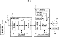
図1に示すように、クレーン操作者が操作する無線送信機1の操作指示を無線受信機2が受け取り、無線受信機2がクレーン制御機3へ操作指示を伝える。これにより、クレーン制御機3は、ブレーキ14、モータ15を動作させることでクレーンが動作する。
As shown in FIG. 1, the
無線受信機2は、アンテナ4、通信部5、無線受信機用の制御部6、無線受信機用の記憶部7及び出力部8を有する。クレーン制御機3は、無線入力部9、クレーン制御部10、クレーン記憶部11、表示部12及び表示操作入力部13を有する。
The
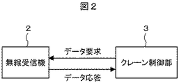
無線受信機2がクレーン制御機3へ操作指示を伝えるために、無線受信機2の出力部8とクレーン制御部3の無線入力部9の接続は、例えば、図2に示すようにシリアル通信で実施する。クレーン制御部3が無線受信機2に対して、データ要求コマンドを送信することで、無線受信機2はデータ要求コマンドに応じたデータをクレーン制御部3への応答として出力する。
In order for the
データ要求コマンドは、例えば、無線送信機1の操作情報や、無線受信機2の異常検出情報等の内部データを取得できるよう、取得するデータ分類毎に分けていても良い。あるいは、全ての情報を一つの要求コマンドで全て取得できるようにしても良い。
The data request command may be divided for each data classification to be acquired so that internal data such as operation information of the
ここで、クレーンを運転する場合、位置決めのためや、吊荷の玉掛け状態を確かめるために、短い時間間隔、例えば200ms以下の時間間隔で動作・停止を繰り返す運転、すなわちインチング運転が必要となる。インチング運転を可能とするために、無線受信機2の操作情報の取得は短時間で実施するのが望ましい。このため、データ要求コマンドを送信するタイミングは、例えば、2ms間隔で実施すれば、クレーン制御部10の処理時間及びブレーキ14の動作時間を加味しても、十分なインチング運転が可能となる。
Here, when the crane is operated, an operation that repeats the operation / stop at a short time interval, for example, a time interval of 200 ms or less, that is, an inching operation is required for positioning or confirming the slung state of the suspended load. In order to enable inching operation, it is desirable to acquire the operation information of the
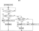
次に、図3を参照して、クレーン制御機3が無線受信機2の操作情報を取得する処理について説明する。
Next, a process in which the
クレーン制御部10は取得した操作情報をもとにブレーキ14及びモータ15を制御してクレーンを動作させる。しかし、ノイズ等の影響で通信波形が乱れ、操作情報が認識できない状態が連続すると暴走の恐れがある。よって、このような認識できない状態が連続した場合は、クレーンを停止させる処理をクレーン制御部10は実施する。
The
図3を参照すると、まず、データ受信済みであるか確認する(S101)。データ受信済みであるのならば、受信したデータが正常であるか確認する(S102)。受信したデータが異常であれば、5回連続異常データを受信したのかを確認する(S105)。異常データ受信回数が5回未満ならば、異常データ受信カウントを+1する(S108)。異常データ受信回数が5回以上であるならば、今まで保持していた操作情報を全てクリアするとともに(S106)、クレーンを停止させる処理を実行する(S107)。受信データが正常である場合は、異常データ受信回数をクリアするとともに(S103)、受信したデータから操作情報を取得する(S104)。このようにして、操作情報検出処理が完了する。 Referring to FIG. 3, first, it is confirmed whether data has been received (S101). If the data has been received, it is confirmed whether the received data is normal (S102). If the received data is abnormal, it is confirmed whether the abnormal data has been received five times (S105). If the number of abnormal data reception is less than 5, the abnormal data reception count is incremented by 1 (S108). If the abnormal data reception count is 5 times or more, all the operation information held so far is cleared (S106), and a process of stopping the crane is executed (S107). If the received data is normal, the abnormal data reception count is cleared (S103), and operation information is acquired from the received data (S104). In this way, the operation information detection process is completed.
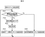
次に、図4を参照して、クレーン制御機3が無線受信機2へ送信する要求コマンドを選択する処理について説明する。
Next, with reference to FIG. 4, the process which selects the request command which the
無線受信機2が検出したエラー情報等の内部データ取得を、操作情報取得のためのデータ要求コマンドと分ける場合、内部データ取得時には、同時に操作情報を取得できない。このため、操作情報の取得が遅れ、操作のレスポンスが悪くなることが想定される。
When internal data acquisition such as error information detected by the
そこで、内部データ取得時には、クレーンの動作を禁止させることで、操作のレスポンスや取得するデータ数を気にすることなく通信が可能となる。なお、無線受信機2の内部データを確認する際は、クレーン制御機3の操作入力部13や表示部12の近くに居る必要がある。通常、クレーン制御機3はクレーンに取付けられているため、安全のためクレーンを操作しながら内部データを確認することはない。よって、内部データ取得時、クレーンの動作を禁止しても問題はない。
Therefore, when internal data is acquired, by prohibiting the operation of the crane, communication is possible without worrying about the response of the operation or the number of data to be acquired. When confirming the internal data of the
図4を参照すると、クレーン制御機3が無線受信機2へ送信する要求コマンドを選択する処理は、まず、クレーン制御機3の表示操作入力部13により、無線受信機2の内部データを表示させる操作がされているか判断する(S201)。内部データを表示させる操作がされていれば、現在の操作情報をクリアするとともに(S202)、クレーンの停止処理を実施し(S203)、内部データ要求コマンド送信処理を実施する(S204)。内部データを表示させる操作がされていなければ、操作情報要求コマンド送信処理を実施する(S205)。このようにして、要求コマンド送信処理が完了する。
Referring to FIG. 4, in the process of selecting a request command to be transmitted from the
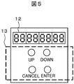
図1に示すように、クレーン制御機3は、受信した内部データを表示させるため、表示部12と表示操作入力部13を備える。図5は、表示部12と表示操作入力部13の配置を示した図である。
As shown in FIG. 1, the
図5を参照すると、表示部12は、例えば、7セグメントLED表示器を用いる。一方、表示操作入力部13は数値等変更するための、UPキー、DOWNキー、変更した数値等を決定するENTERキー、変更した数値をもとに戻す等のCANCELキーを備える。
Referring to FIG. 5, the
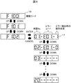
図6は、実際に無線受信機2の内部データの表示例である。無線受信機2の各内部データを機能コード16に割り振り、表示操作入力部13のUPキー、DOWNキーを操作しながら、表示させたい内部データを表示操作入力部13で選択する。表示させたい内部データが割り振られた機能コード16が決定したら、表示操作入力部13のENTERキーを押すことで、表示部12に内部データを表示する。
FIG. 6 is a display example of internal data of the
図6に示すように、表示部12に表示される内部データ17は、来歴No、エラーコード、エラー検出時の操作状態から成る。そして、表示部12に表示される内部データ17は、表示操作入力部13のUPキー、DOWNキーを操作しながら、順次表示部12に表示される。このようにして、表示部12に内部データを表示することができるので、内部データを変更して、無線受信機2に設定することも可能である。
As shown in FIG. 6, the
ここで、内部データとは、例えば上記したように、来歴No、エラーコード、エラー検出時の操作状態を含む概念である。 Here, the internal data is a concept including a history number, an error code, and an operation state at the time of error detection, for example, as described above.
本実施の形態1により、無線受信機2が検出したエラー情報や運転情報等を表示することで、無線受信機2の異常発生時の要因解析が容易になる。さらに、無線受信機2の内部データが変更できるので、使用するクレーンに合わせた最適な設定のカスタマイズが容易になる。
According to the first embodiment, by displaying error information, operation information, and the like detected by the
本実施の形態1は、図5に示す表示部12によって、7セグメントLEDにより文字情報をユーザに伝達することができるが、表示部12の変形例について図13を用いて説明する。
In the first embodiment, character information can be transmitted to the user by the 7-segment LED by the
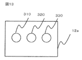
図13に表示部12aを示し、左から順に第1のLED310、第2のLED320、第3のLED330が配置されている。本変形例は、図5に示す表示部12の代わりに表示部12aを接続することにより実施可能である。これらのLED310、320、330は予め表示内容を特定しておくことで、任意の情報を表示することができる。その一例について説明する。
FIG. 13 shows the
第1のLED310は、無線通信手段が受信する電界強度を示す。電界強度が通信に十分な場合に点灯し、電界強度が通信に不十分な場合に消灯することで、正常な通信を維持することを示すことができる。他方、電界強度が不十分な場合に点灯することもでき、この場合は、エラー状態を示すことが可能である。
The
また、電界強度を示す第1のLED310は複数のLEDであっても実施でき、この場合は、電界強度を複数段階で表現することができる。例えば、第1のLED310を3つ設けた場合について説明する。
The
第1のLED310が2つ点灯していれば通信に適した電界強度である場合、1つ点灯していれば通信はできるが電界強度が2つ点灯した状態よりも弱い場合、3つ点灯していれば2つ点灯した状態よりも強い電界強度である場合を示すことができる。また、第1のLED310が3つとも消灯していれば、通信ができない程度の電界強度であることを示すことができる。
If the
さらに、第1のLEDが1つの場合に、LEDをPWM(pulse width modulation)駆動させ、デューティ比を変えることで第1のLED310の明るさを変更することができる。これにより、操作者が視認できる明るさが変更され、電界強度を示すことができる。また、デューティ比の変更によって明るさを調整し、さらに例えば、ディーティ比50%とディーティ比0%を交互に所定時間繰り返すことで、特定の明るさとON/OFF状態を組み合わせることも可能である。
Furthermore, when there is one first LED, the brightness of the
また、第2のLED320は、操作情報の一例として、操作者がモータ駆動装置等に異常を検出した場合に、入力部に警報を発信する情報を入力すると、モータ駆動装置に取り付けられた警報が鳴っている状態に点灯する。
Further, as an example of the operation information, the
これにより、操作者が警報を発信する信号が送信されたことを視覚的に知ることができる。さらに、他の一例として、モータ駆動装置に取り付けられた照明のON/OFF情報、主電源のON/OFF情報を示すことができる。 As a result, the operator can visually know that a signal for transmitting an alarm has been transmitted. Furthermore, as another example, ON / OFF information of lighting attached to the motor drive device and ON / OFF information of the main power source can be shown.
次に、第3のLED330により、通信データエラーの確認をする方法について説明する。通信されたパケットについてオーバーラン、パリティ等の検定を行い、検定結果が正しい場合、すなわち通信が正常に行われている際には点灯する。あるいは、正常時に消灯してもよい。
Next, a method for confirming a communication data error using the
上記した変形例により、LED310、320、330と予め特定された表示する情報が1対1の関係となることで、操作者がLED310、320、330のON/OFF状態またはその明るさを確認するだけで、瞬時にモータ駆動装置に関する状態または操作情報を確認することができる。
By the above-described modification, the
上記した本発明の実施の形態1によれば、クレーンを制御する制御機器が有する内部データをユーザが取得することが可能となる。また、クレーンを制御する制御機器が異常動作をした場合に、無線受信機の異常であるのか、あるいはクレーンを制御する制御機器の異常であるのかの判断に役立てることが可能となる。 According to the first embodiment of the present invention described above, the user can acquire the internal data of the control device that controls the crane. Further, when the control device that controls the crane performs an abnormal operation, it can be used to determine whether the wireless receiver is abnormal or the control device that controls the crane is abnormal.
次に、図7〜図12を参照して、実施の形態2について説明する。
Next,
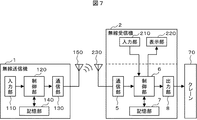
まず、図7を参照すると、クレーン操作者が操作する無線送信機1は、送信機用の入力部110、送信機用の制御部120、送信機用の通信部130、送信機用の記憶部140及び送信機用のアンテナ150を有する。一方、無線送信機1の電波を受信する無線受信機7は、受信機用の通信部5、受信機用の制御部6、受信機用の出力部8、受信機用の記憶部7、受信機用のアンテナ230、受信機用の入力部210及び受信機用の表示部220を有する。
First, referring to FIG. 7, a
無線操作の制御の流れは、送信機用の入力部110の状態を送信機用の制御部120が判断し、送信機用の通信部130より操作指示を無線通信で発信する。無線受信機2は、無線送信機1からの無線通信を受信機用の通信部5で受信し、受信機用の制御部6で制御を判断し、受信機用の出力部8から操作信号を出力することによりクレーン70の運転を制御する。
The flow of wireless operation control is determined by the
一般的に、クレーン70に使用される特定小電力の無線機は、個別の識別番号(ID)を持ち、無線送信機1から送信されてくる通信データにID情報も含まれている。そして、無線受信機2は、受信したID情報が自身の持つID情報と一致しなければ、その通信による制御を実施しないようになっている。
In general, a specific low-power radio device used for the
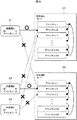
図8に示すように、複数台の無線機がある場合において、受信機A24は自身の電源が投入されたら、自身のIDと合致する送信機A21の通信を受信するまで、無線通信周波数帯(チャンネル)を順次切り替える。IDが異なる送信機B22又は送信機C23の通信を受信した場合は、その通信を無視する。送信機A21の通信を受信すると、そのチャンネルに固定される。 As shown in FIG. 8, in the case where there are a plurality of wireless devices, when the receiver A24 is powered on, the wireless communication frequency band (until the communication of the transmitter A21 that matches its own ID is received. (Channel) sequentially. When the communication of the transmitter B22 or the transmitter C23 having a different ID is received, the communication is ignored. When the communication of the transmitter A21 is received, the channel is fixed.
上記通信方式により、合致するIDが無ければ、順次チャンネルを切り替えるので、合致する送信機の電源を投入しなければ、各チャンネルの通信状態が判別可能になる。 According to the above communication method, if there is no matching ID, the channels are sequentially switched. Therefore, if the matching transmitter is not turned on, the communication state of each channel can be determined.
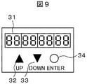
図9は、入力部210及び表示部220の例である。無線受信機2にある入力部210は、例えば、UPボタン32、DOWNボタン33、ENTERボタン34で構成される。また、表示部220は、例えば、7セグメントLED31で構成される。
FIG. 9 is an example of the input unit 210 and the
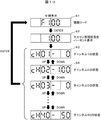
図10は、各チャンネルの通信状態の表示例である。ここで、図10において、手順41は、チャンネルスキャンを実行する機能コード表示を示し、手順42は、全チャンネルのスキャン状態表示を示す。また、手順43は、チャンネル1の空き状態表示を示し、手順44は、チャンネル2の空き状態表示を示す。
FIG. 10 is a display example of the communication state of each channel. Here, in FIG. 10, a
図10を参照すると、各チャンネル状態のスキャンを開始するために、まず、チャンネルスキャンを実行する機能コード「F100」を選択表示する(手順41)。「F100」を選択表示したら、次に、ENTERボタン34を押すと全チャンネルスキャンを実施する(手順42)。
Referring to FIG. 10, in order to start scanning of each channel state, first, a function code “F100” for executing channel scanning is selectively displayed (procedure 41). After selecting and displaying “F100”, next, when the
全チャンネルのスキャン状態はパーセントで表示され、100%になると自動的にチャンネル1の空き状態が表示される(手順43)。他のチャンネルの状態が見たい場合はUPボタン32又はDOWNボタン33を操作することで、表示が切り替わる(手順44)。
The scan status of all channels is displayed as a percentage, and when 100% is reached, the free status of
空き状態は、3段階で表示され、「0」が他に使用している無線機がない状態で、「100」が他の無線機が占有している状態を示す。「50」は何らかの影響で一時的にそのチャンネルに電波干渉があることを示す。ここで、例えば、チャンネルの空き状態の表示はパーセント表示で実施しても良い。また、例えば、液晶表示器(図示せず)を使用すれば、全チャンネルの空き状態を一括で表示することもできる。 The vacant state is displayed in three stages, and “0” indicates a state in which no other wireless device is used, and “100” indicates a state occupied by another wireless device. “50” indicates that the channel temporarily has radio wave interference due to some influence. Here, for example, the display of the channel availability may be performed in percentage display. Further, for example, if a liquid crystal display (not shown) is used, it is possible to collectively display the vacant states of all channels.
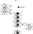
図11は、チャンネル設定の操作方法を示す例である。ここで、図11において、手順51は、チャンネル変更を実行する機能コード表示を示し、手順52は、現在選択しているチャンネル表示を示す。また、手順53は、チャンネル変更状態表示を示し、手順54は、チャンネル1の選択状態表示を示す。
FIG. 11 is an example showing a channel setting operation method. Here, in FIG. 11, a
チャンネルの空き状況表示により、受信機の空きチャンネルを固定したい場合は、まず、チャンネル変更を実行する機能コード「F200」を選択表示する(手順51)。「F200」を選択表示したらENTERボタン34を押すと、現在選択しているチャンネルが表示される(手順52)。ここで、「cH−−」の表示はチャンネルを固定していない状態を表す。すなわち、図8のように順次チャンネルを変化させて、一致するIDを探す状態を示す。現在選択しているチャンネル表示中に、ENTERボタン34を押すと、表示しているチャンネル部が点滅表示になる(手順53)。点滅表示後、UPボタン32またはDOWNボタン33を押すことによりチャンネルを選択することができる(手順54)。そして、設定したいチャンネルが表示されたら、ENTERボタン34を押すことにより、点滅表示が終了し、チャンネルが設定される(手順55)。無線受信機2に設定されたチャンネルは受信機用の記憶部7に記憶され、電源が遮断されても消去されることはない。
When it is desired to fix the vacant channel of the receiver based on the channel vacancy status display, the function code “F200” for executing the channel change is first selected and displayed (procedure 51). When “F200” is selected and displayed, the
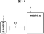
図12は、無線送信機1のチャンネルの変更方法を示す例である。上述のように、空きチャンネルが判別でき、無線受信機2のチャンネルを変更できる。しかし、無線送信機1のチャンネルも変更しないと、空きチャンネルを使用することができない。無線送信機1のチャンネルを変更するための方法として、例えば、無線送信機1と無線受信機2を設定変更ケーブル61で接続する。このような構成の下、上述の手順により、無線受信機2に設定されたチャンネルを無線送信機1に送信し、無線送信機1のチャンネルを変更する。無線送信機1に設定されたチャンネルは送信機用の記憶部140に記憶され、電源が遮断されても消去されることはない。
FIG. 12 is an example showing a method of changing the channel of the
ここで、無線送信機1のチャンネルを変更する方法として、設定変更用の治具(図示せず)を使用しても良い。また、図7に示す入力部210及び表示部220が無線受信機2から分離でき、無線送信機1と接続できる構造にすることにより、図11に示す手順で、チャンネルの設定ができるようにしても良い。
Here, as a method of changing the channel of the
なお、図7に示す入力部210及び表示部220は、クレーン側のクレーン制御機に設けても良い(例えば、図1に示すクレーン制御機3の表示操作入力部13及び表示部12参照)。図1に示すように、クレーン側のクレーン制御機3に設ける場合は、クレーン側のクレーン制御機3と無線受信機2の制御部6が通信できる構成である必要がある。
Note that the input unit 210 and the
上記実施の形態2により、クレーンを制御する制御機器が有する内部データをユーザが取得することが可能となる。空きチャンネルが確認でき、また、どのチャンネルに設定するか選択できる。この結果、同一無線機器の複数台運用が容易になる。容易に各チャンネルの状態が確認できるので、操作中にクレーンが停止してしまう等の電波の混信が生じ得る場合に、混信原因の解析及び対策の検討に役立てることが可能となる。 According to the second embodiment, the user can acquire the internal data of the control device that controls the crane. You can check available channels and select which channel to set. As a result, the operation of a plurality of the same wireless devices becomes easy. Since the state of each channel can be easily confirmed, it can be used for analysis of the cause of interference and examination of countermeasures when radio interference such as a crane stopping during operation can occur.
以上、本発明者によってなされた発明をその実施の形態に基づき具体的に説明したが、本発明は前記実施の形態に限定されるものではなく、その要旨を逸脱しない範囲で種々変更可能であることは言うまでもない。例えば、前記表示部は、操作者がエラー情報あるいはチャンネルの状態を確認できるのならば、クレーン用無線操作装置等の吊上げ装置とは異なる位置(例えば、天井等)に配置しても良い。 As mentioned above, the invention made by the present inventor has been specifically described based on the embodiment. However, the invention is not limited to the embodiment, and various modifications can be made without departing from the scope of the invention. Needless to say. For example, the display unit may be disposed at a position (for example, a ceiling or the like) different from a lifting device such as a crane wireless operation device as long as the operator can check error information or a channel state.
1 無線送信機
2 無線受信機
3 クレーン制御機
4 受信機用アンテナ
5 通信部
6 制御部
7 記憶部
8 出力部
9 無線入力部
10 クレーン制御部
11 クレーン記憶部
12 表示部
13 表示操作入力部
14 ブレーキ
15 モータ
16 機能コード
17 内部データ表示例
21 送信機A
22 送信機B
23 送信機C
24 受信機A
25 受信機B
31 7セグメントLED
32 UPボタン
33 DOWNボタン
34 ENTERボタン
41 チャンネルスキャンを実行する機能コード表示
42 全チャンネルのスキャン状態表示
43 チャンネル1の空き状態表示
44 チャンネル2の空き状態表示
51 チャンネル変更を実行する機能コード表示
52 現在選択しているチャンネル表示
53 チャンネル変更状態表示
54 チャンネル1選択状態表示
61 設定変更ケーブル
70 クレーン
110 入力部
120 制御部
130 通信部
140 記憶部
150 送信機用アンテナ
230 受信機用アンテナ
210 入力部
220 表示部
DESCRIPTION OF
22 Transmitter B
23 Transmitter C
24 Receiver A
25 Receiver B
31 7 segment LED
32
Claims (6)
前記無線受信機から取得した内部データを表示する表示部と、
前記操作情報に基づいて前記クレーンを動作させるクレーン制御機と、
を有し、
前記クレーン制御機は、前記クレーンの動作を停止させた状態で、前記無線受信機から前記内部データを取得することを特徴とする吊上げシステム。 A wireless receiver for receiving at least operation information for operating the crane from a wireless transmitter for transmitting operation instructions;
A display unit for displaying internal data acquired from the wireless receiver;
A crane controller for operating the crane based on the operation information;
I have a,
The lifting system according to claim 1, wherein the crane controller acquires the internal data from the wireless receiver in a state where the operation of the crane is stopped .
前記内部データを前記記憶部に記憶することを特徴とする請求項1に記載の吊上げシステム。 The wireless receiver has a storage unit,
The lifting system according to claim 1, wherein the internal data is stored in the storage unit.
前記表示操作入力部により前記内部データを表示させる操作がされているか判断し、
前記内部データを表示させる操作がされていれば、現在の前記操作情報をクリアするとともに前記クレーンの停止処理を実施し、前記無線受信機へ内部データ要求コマンドを送信し、
前記内部データを表示させる操作がされていなければ、前記無線受信機へ操作情報要求コマンドを送信することを特徴とする請求項4に記載の吊上げシステム。 The crane controller is
Determining whether or not an operation for displaying the internal data is performed by the display operation input unit;
If the operation to display the internal data is being performed, the current operation information is cleared and the crane stop process is performed, and an internal data request command is transmitted to the wireless receiver.
The lifting system according to claim 4 , wherein if the operation for displaying the internal data is not performed, an operation information request command is transmitted to the wireless receiver .
Priority Applications (1)
| Application Number | Priority Date | Filing Date | Title |
|---|---|---|---|
| JP2017171902A JP6580098B2 (en) | 2017-09-07 | 2017-09-07 | Lifting system |
Applications Claiming Priority (1)
| Application Number | Priority Date | Filing Date | Title |
|---|---|---|---|
| JP2017171902A JP6580098B2 (en) | 2017-09-07 | 2017-09-07 | Lifting system |
Publications (2)
| Publication Number | Publication Date |
|---|---|
| JP2019043767A JP2019043767A (en) | 2019-03-22 |
| JP6580098B2 true JP6580098B2 (en) | 2019-09-25 |
Family
ID=65813704
Family Applications (1)
| Application Number | Title | Priority Date | Filing Date |
|---|---|---|---|
| JP2017171902A Active JP6580098B2 (en) | 2017-09-07 | 2017-09-07 | Lifting system |
Country Status (1)
| Country | Link |
|---|---|
| JP (1) | JP6580098B2 (en) |
Family Cites Families (4)
| Publication number | Priority date | Publication date | Assignee | Title |
|---|---|---|---|---|
| JPS63288893A (en) * | 1987-05-19 | 1988-11-25 | アンリツ株式会社 | Data transmitter |
| JP3245283B2 (en) * | 1993-11-05 | 2002-01-07 | 鹿島建設株式会社 | Crane control device with operating status display device |
| JP4145616B2 (en) * | 2002-09-30 | 2008-09-03 | 金陵電機株式会社 | Remote control device |
| US8554378B2 (en) * | 2011-03-08 | 2013-10-08 | Magnetek, Inc. | System for control of mobile hydraulic equipment |
-
2017
- 2017-09-07 JP JP2017171902A patent/JP6580098B2/en active Active
Also Published As
| Publication number | Publication date |
|---|---|
| JP2019043767A (en) | 2019-03-22 |
Similar Documents
| Publication | Publication Date | Title |
|---|---|---|
| JP5678136B2 (en) | Lighting control method and system | |
| EP1498082B1 (en) | Operating system having a plurality of medical devices and a plurality of remote control devices | |
| EP2908302B1 (en) | Operation terminal apparatus for manufacturing apparatus, and manufacturing system including the same | |
| US20180091216A1 (en) | Controller in wireless communication with operation panel, wireless module, and wireless repeater | |
| CN106304537A (en) | Ligthing paraphernalia and illuminator | |
| JP6616364B2 (en) | Wireless device system | |
| JP6580098B2 (en) | Lifting system | |
| JP5333828B2 (en) | Remote control device and device control system | |
| US9544315B2 (en) | Access-level control apparatus | |
| US20100075601A1 (en) | Wireless Communication Apparatus and Wireless Communication Method | |
| EP3280152A1 (en) | Transmission device, receiving device, and communication system and remote operation device provided with same | |
| JP4145616B2 (en) | Remote control device | |
| JP6830208B2 (en) | Lighting systems, luminaires, and how to pair lighting systems | |
| JP2011143976A (en) | Member kitting instruction device and member kitting instruction system using the same | |
| JP5491710B2 (en) | DVOR (Doppler VHF omnidirectionalRadioRange) system, monitor device, and DVOR device monitoring method | |
| JP7012456B2 (en) | Lighting equipment and lighting system | |
| KR101625872B1 (en) | system and method of providing vehicle light control based on events of smart terminal, and computer-readable recording medium for the same | |
| JP2019011160A (en) | Elevator monitoring system | |
| JP6808185B2 (en) | Solenoid valve remote control device | |
| JP2010165522A (en) | Lighting system | |
| EP3396872B1 (en) | State display apparatus, state display system, and radio transmission apparatus | |
| US10266018B2 (en) | Communication system and communication apparatus | |
| KR102259471B1 (en) | Communication device, radio communication device, lighting device, lighting system, communication method, and program stored in storage medium | |
| US9923419B2 (en) | Electric power transmitter, electric power transmission method and semiconductor device | |
| TW202347974A (en) | Transmitting device, transmitting method, and receiving device capable of improving a data transmission rate when transmitting data using a frequency hopping method |
Legal Events
| Date | Code | Title | Description |
|---|---|---|---|
| A621 | Written request for application examination |
Free format text: JAPANESE INTERMEDIATE CODE: A621 Effective date: 20180313 |
|
| A977 | Report on retrieval |
Free format text: JAPANESE INTERMEDIATE CODE: A971007 Effective date: 20190117 |
|
| A131 | Notification of reasons for refusal |
Free format text: JAPANESE INTERMEDIATE CODE: A131 Effective date: 20190122 |
|
| A521 | Written amendment |
Free format text: JAPANESE INTERMEDIATE CODE: A523 Effective date: 20190318 |
|
| TRDD | Decision of grant or rejection written | ||
| A01 | Written decision to grant a patent or to grant a registration (utility model) |
Free format text: JAPANESE INTERMEDIATE CODE: A01 Effective date: 20190806 |
|
| A61 | First payment of annual fees (during grant procedure) |
Free format text: JAPANESE INTERMEDIATE CODE: A61 Effective date: 20190827 |
|
| R150 | Certificate of patent or registration of utility model |
Ref document number: 6580098 Country of ref document: JP Free format text: JAPANESE INTERMEDIATE CODE: R150 |