JP6579373B2 - Toilet device - Google Patents
Toilet device Download PDFInfo
- Publication number
- JP6579373B2 JP6579373B2 JP2015191737A JP2015191737A JP6579373B2 JP 6579373 B2 JP6579373 B2 JP 6579373B2 JP 2015191737 A JP2015191737 A JP 2015191737A JP 2015191737 A JP2015191737 A JP 2015191737A JP 6579373 B2 JP6579373 B2 JP 6579373B2
- Authority
- JP
- Japan
- Prior art keywords
- tank device
- pedestal
- tank
- toilet
- port
- Prior art date
- Legal status (The legal status is an assumption and is not a legal conclusion. Google has not performed a legal analysis and makes no representation as to the accuracy of the status listed.)
- Active
Links
Images


Description
本発明は、便器装置に係り、特に、便器後部のキャビネットパネル内に隠蔽された状態で配置されるタンク装置を備えた便器装置に関する。 The present invention relates to a toilet device, and more particularly to a toilet device provided with a tank device arranged in a concealed state in a cabinet panel at the rear of the toilet.
従来から、特許文献1に示すように、便器後部のキャビネットパネル内に隠蔽された状態で配置されるタンク装置を備えた便器装置が知られている。
特許文献1に示すような従来の便器装置においては、タンク装置と、タンク装置を固定するタンク装置固定台座との間の流路の接続部分を排水パッキンにより適切にシールするため、タンク装置を上方からタンク装置固定台座上に取付けて、タンク装置とタンク装置固定台座との間に排水パッキンを取付ける方法が採用されていた。
Conventionally, as shown in
In the conventional toilet device as shown in
しかしながら、意匠性や、便器装置を設置する現場のキャビネットの高さが制限される観点から、キャビネットの高さを比較的低く抑えることが求められている。キャビネットの高さを比較的低く抑える場合、タンク装置を取付けるための施工スペースが比較的狭くなり、キャビネット内でタンク装置を上方からタンク装置固定台座上に取付けることができない又は取付けにくくなる場合があるという問題が生じていた。 However, it is required to keep the height of the cabinet relatively low in terms of design and the height of the cabinet on the site where the toilet device is installed. If the height of the cabinet is kept relatively low, the construction space for installing the tank device will be relatively narrow, and it may not be possible or difficult to install the tank device on the tank device fixing base from above in the cabinet. There was a problem.
また、キャビネット内においてタンク装置をタンク装置固定台座上に取付ける施工スペースが比較的狭くなる場合に、タンク装置を、キャビネットパネルの正面側に形成された取付口から、キャビネット内部のタンク装置固定台座上に取付けることが検討されたが、タンク装置を正面から奥側に向かって横向きに挿入するように取付けることとなるため、タンク装置と、タンク装置固定台座との間において、排水パッキンが横向きにずれやすく、排水パッキンのめくれを生じさせ、漏水を発生させてしまうという問題が生じた。 In addition, when the installation space for mounting the tank device on the tank device fixing base in the cabinet becomes relatively small, the tank device can be mounted on the tank device fixing base inside the cabinet from the mounting port formed on the front side of the cabinet panel. However, since the tank device is mounted so as to be inserted sideways from the front side to the back side, the drain packing is shifted laterally between the tank device and the tank device fixing base. It was easy to cause a problem that the drain packing was turned up and water leakage occurred.
さらに、タンク装置を、キャビネットパネルの正面側に形成された取付口から、キャビネット内部のタンク装置固定台座上に取付ける場合には、施工者からタンク装置の奥側が非常に視認しにくい状況となるため、タンク装置と、タンク装置固定台座との取付けが不良となるという問題が生じた。さらに、このように取付けが難しく位置の修正を行うことが必要となることにより、排水パッキンがずれて排水パッキンのめくれを生じさせ、漏水を発生させてしまうという問題も生じることとなった。 Furthermore, when the tank device is mounted on the tank device fixing base inside the cabinet from the mounting opening formed on the front side of the cabinet panel, it is difficult for the installer to see the back side of the tank device. There is a problem that the mounting of the tank device and the tank device fixing base becomes defective. In addition, since it is difficult to mount in this way and it is necessary to correct the position, the drainage packing is displaced, causing the drainage packing to be turned up and causing water leakage.
そこで、本発明は、上述した従来技術の問題を解決するためになされたものであり、比較的狭い施工スペースであっても、便器後部のキャビネットパネル内に隠蔽された状態で配置されるタンク装置を、キャビネットパネルの正面側に形成された取付口からタンク装置固定台座ユニットに取付けることができると共に、取付けの際の排水パッキンのめくれを防止することができ、タンク装置の底部が、タンク装置の排水口と接続流路との接合部分の外側を排水パッキンによりシールした状態で、タンク装置固定台座ユニットに取付けられることができる便器装置を提供することを目的としている。 Accordingly, the present invention has been made to solve the above-described problems of the prior art, and a tank apparatus that is concealed in a cabinet panel at the rear of the toilet bowl even in a relatively narrow construction space. Can be attached to the tank device fixing pedestal unit from the mounting opening formed on the front side of the cabinet panel, and the drainage packing can be prevented from being turned over during the installation. It aims at providing the toilet device which can be attached to a tank apparatus fixed base unit in the state which sealed the outer side of the junction part of a drain outlet and a connection flow path by drainage packing.
上述した目的を達成するために、本発明は、便器後部のキャビネットパネル内に隠蔽された状態で配置されるタンク装置を備えた便器装置であって、後部に給水口を有し且つこの給水口から供給された洗浄水により汚物を排出する便器本体と、便器本体へ供給する洗浄水を貯水するタンク装置と、タンク装置の底部の排水口の外側に環状に設けられる排水パッキンと、タンク装置の底部を着座するタンク装置固定台座ユニットであって、タンク装置の底部の排水口と接続される接続流路を形成しているタンク装置固定台座ユニットと、タンク装置固定台座ユニットの下部と便器本体の給水口とを接続する給水管とを有し、タンク装置固定台座ユニットは、上方に突出した台座凸部又は下方にくぼまされた台座凹部を備え、タンク装置の底部は、上方に突出した台座凸部と嵌合する凹部、又は下方にくぼまされた台座凹部と嵌合する凸部、を備え、タンク装置の底部又はタンク装置固定台座ユニットは、タンク装置の底部をタンク装置固定台座ユニット上で、キャビネットパネルの正面側に形成された取付口からキャビネットパネル後方の所定の着座位置まで前後方向にスライドさせることができるリブを備え、タンク装置の底部が所定の着座位置に到達した状態で、台座凸部と嵌合する凹部、又は台座凹部と嵌合する凸部の組合せのいずれかの構造により、タンク装置の底部がタンク装置固定台座ユニット上に沈み込むように下降され、排水パッキンを下方に押圧することとなり、タンク装置の底部が、タンク装置の排水口と接続流路との接合部分の外側を排水パッキンによりシールした状態で、タンク装置固定台座ユニットに取付けられることを特徴としている。
このように構成された本発明においては、タンク装置の底部をタンク装置固定台座ユニット上で、キャビネットパネルの正面側に形成された取付口からキャビネットパネル後方の所定の着座位置まで前後方向にスライドさせることができ、タンク装置の底部が所定の着座位置に到達した状態で、台座凸部と嵌合する凹部、又は台座凹部と嵌合する凸部の組合せのいずれかの構造により、タンク装置の底部がタンク装置固定台座ユニット上に沈み込むように下降され、排水パッキンを下方に押圧することとなるので、排水パッキンのめくれを防止することができ、排水パッキンのめくれによる漏水の発生を防止することができる。従って、比較的狭い施工スペースであっても、便器後部のキャビネットパネル内に隠蔽された状態で配置されるタンク装置を、キャビネットパネルの正面側に形成された取付口からタンク装置固定台座ユニットに取付けることができると共に、取付けの際の排水パッキンのめくれを防止することができ、タンク装置の底部が、タンク装置の排水口と接続流路との接合部分の外側を排水パッキンによりシールした状態で、タンク装置固定台座ユニットに取付けられることができる。
In order to achieve the above-described object, the present invention is a toilet device provided with a tank device arranged in a concealed state in a cabinet panel at the rear of the toilet bowl, and has a water supply port at the rear and the water supply port. A toilet body that discharges filth by the wash water supplied from the tank, a tank device that stores the wash water to be supplied to the toilet body, a drain packing provided in an annular shape outside the drain port at the bottom of the tank device, and a tank device A tank device fixed pedestal unit seated on the bottom, which forms a connection channel connected to a drain outlet at the bottom of the tank device, a lower portion of the tank device fixed pedestal unit, and a toilet body The tank apparatus fixed pedestal unit includes a pedestal convex part protruding upward or a pedestal concave part recessed downward, and the bottom part of the tank apparatus has a water supply pipe connected to the water supply port. A bottom part of the tank device or a tank device fixed base unit is provided with a concave part that fits with a pedestal convex part that protrudes upward, or a convex part that fits with a dent part concaved downward. On the fixed base unit, it is equipped with a rib that can be slid in the front-rear direction from a mounting opening formed on the front side of the cabinet panel to a predetermined seating position behind the cabinet panel, and the bottom of the tank device reaches the predetermined seating position In such a state, the bottom of the tank device is lowered so as to sink onto the tank device fixed pedestal unit by the structure of either the concave portion fitted to the pedestal convex portion or the combination of the convex portion fitted to the pedestal concave portion, The drainage packing is pressed downward, and the bottom of the tank device seals the outside of the joint between the drainage port of the tank device and the connection channel with the drainage packing. In state, it is characterized in that attached to the tank unit fixed base unit.
In the present invention configured as described above, the bottom of the tank device is slid in the front-rear direction on the tank device fixing base unit from the mounting opening formed on the front side of the cabinet panel to a predetermined seating position behind the cabinet panel. The bottom of the tank device can be configured by either a recess that fits with the pedestal projection or a combination of projections that fit with the pedestal recess when the bottom of the tank device reaches a predetermined seating position. Is lowered so that it sinks on the tank device fixed pedestal unit, and the drainage packing is pressed downward, so that the drainage packing can be prevented from being turned up, and the occurrence of water leakage due to the turnup of the drainage packing can be prevented. Can do. Therefore, even in a relatively narrow construction space, the tank device that is concealed in the cabinet panel at the rear of the toilet bowl is attached to the tank device fixing pedestal unit from the attachment port formed on the front side of the cabinet panel. In addition to being able to prevent the drain packing from being turned over during installation, the bottom of the tank device seals the outside of the joint between the drain port of the tank device and the connection flow path with the drain packing, It can be attached to the tank device fixed base unit.
本発明において、好ましくは、タンク装置固定台座ユニットは、前方部分において、台座凸部又は台座凹部を備え、タンク装置の底部は、前方部分において、台座凸部と嵌合する凹部、又は台座凹部と嵌合する凸部、を備えている。
このように構成された本発明においては、台座凸部と嵌合する凹部、又は台座凹部と嵌合する凸部の組合せのいずれかの構造を、キャビネットパネルの正面側に形成された取付口から容易に目視することができるため、タンク装置の前記底部をタンク装置固定台座ユニット上で、所定の着座位置まで容易にスライドさせることができ、タンク装置の底部を、タンク装置固定台座ユニットに容易に取付けることができる。
In the present invention, preferably, the tank device fixed pedestal unit includes a pedestal convex portion or a pedestal concave portion at a front portion, and a bottom portion of the tank device is a concave portion that fits with the pedestal convex portion or a pedestal concave portion at the front portion. And a convex portion to be fitted.
In the present invention configured as described above, the structure of either the concave portion that fits with the pedestal convex portion or the combination of the convex portion that fits with the pedestal concave portion is formed from the mounting opening formed on the front side of the cabinet panel. The bottom of the tank device can be easily slid to a predetermined seating position on the tank device fixed pedestal unit, and the bottom of the tank device can be easily attached to the tank device fixed pedestal unit. Can be installed.
本発明において、好ましくは、タンク装置固定台座ユニットは、タンク装置の底部の排水口と給水管とを接続する接続流路を形成している接続継手と、タンク装置及び接続継手を支持するタンク支持部材と、を備え、接続継手が、上方に突出した台座凸部を備え、タンク装置の底部のリブを接続継手の台座凸部の上で、キャビネットパネルの正面側に形成された取付口からキャビネットパネル後方の所定の着座位置まで前後方向にスライドさせることができ、タンク装置の底部が所定の着座位置に到達した状態で、台座凸部と嵌合する凹部の構造により、タンク装置の底部が接続継手上に沈み込むように下降され、排水パッキンを下方に押圧することとなり、タンク装置の底部が、タンク装置の排水口と接続流路との接合部分の外側を前記排水パッキンによりシールした状態で、接続継手に取付けられる。
このように構成された本発明においては、タンク装置の底部を接続継手の台座凸部の上で、キャビネットパネルの正面側に形成された取付口からキャビネットパネル後方の所定の着座位置まで前後方向にスライドさせることができ、タンク装置の底部が所定の着座位置に到達した状態で、台座凸部と嵌合する凹部の構造により、タンク装置の底部が接続継手上に沈み込むように下降され、排水パッキンを下方に押圧することとなるので、排水パッキンのめくれを防止することができ、排水パッキンのめくれによる漏水の発生を防止することができる。従って、比較的狭い施工スペースであっても、便器後部のキャビネットパネル内に隠蔽された状態で配置されるタンク装置を、キャビネットパネルの正面側に形成された取付口からタンク装置固定台座ユニットの接続継手上に取付けることができると共に、取付けの際の排水パッキンのめくれを防止することができ、タンク装置の底部が、タンク装置の排水口と接続流路との接合部分の外側を排水パッキンによりシールした状態で、タンク装置固定台座ユニットに取付けられることができる。また、タンク装置の底部の排水口と、接続流路を有する接続継手との位置合わせを容易に行うことができる。
In the present invention, preferably, the tank device fixing base unit includes a connection joint that forms a connection flow path that connects a drain outlet at the bottom of the tank device and a water supply pipe, and a tank support that supports the tank device and the connection joint. And a connecting joint having a pedestal convex part protruding upward, and a rib at the bottom of the tank device is mounted on the pedestal convex part of the connecting joint from a mounting opening formed on the front side of the cabinet panel. It can be slid in the front-rear direction to a predetermined seating position behind the panel, and the bottom of the tank device is connected by the structure of the recess that fits with the base projection when the bottom of the tank device has reached the predetermined seating position. It is lowered so as to sink onto the joint, and the drainage packing is pressed downward, so that the bottom of the tank device is disposed outside the joint portion between the drainage port of the tank device and the connection flow path. While sealed by a packing attached to the connection joint.
In the present invention configured as described above, the bottom of the tank device is placed on the pedestal convex portion of the connection joint in the front-rear direction from the mounting opening formed on the front side of the cabinet panel to the predetermined seating position behind the cabinet panel. When the bottom of the tank device has reached a predetermined seating position, the tank device is lowered so that the bottom of the tank device sinks onto the connection joint due to the structure of the recess that fits with the pedestal protrusion. Since the packing is pressed downward, the drain packing can be prevented from being turned over, and the occurrence of water leakage due to the drain packing being turned up can be prevented. Therefore, even in a relatively narrow construction space, the tank device that is concealed in the cabinet panel at the rear of the toilet bowl is connected to the tank device fixed base unit from the mounting port formed on the front side of the cabinet panel. It can be mounted on the joint and can prevent the drain packing from being turned over during the installation, and the bottom of the tank device seals the outside of the joint between the drain port of the tank device and the connection channel with the drain packing. In this state, it can be attached to the tank device fixed base unit. Further, it is possible to easily align the drain outlet at the bottom of the tank device and the connection joint having the connection flow path.
本発明において、好ましくは、タンク装置の底部は、タンク装置の底部を接続継手の台座凸部上で、キャビネットパネルの正面側に形成された取付口からキャビネットパネル後方の所定の着座位置まで前後方向にスライドさせることができるように、下方に突出するリブを備え、タンク装置の底部の排水口は、タンク装置をスライドさせて取付けるために排水口の外側に排水パッキンが取付けられている状態において、排水パッキンよりも下方まで突出するような長さを有するように形成され、タンク装置の底部の排水口が底部から突出する長さは、接続継手の台座凸部が接続継手から上方に突出する長さと、タンク装置の底部のリブが底部から下方に突出する長さとの和より小さい長さとされている。
このように構成された本発明においては、施工取付け時に、タンク装置の底部の排水口が排水パッキンよりも下方まで突出しており、且つ排水口が底部から突出する長さは、接続継手の台座凸部が接続継手から上方に突出する長さと、タンク装置の底部のリブが底部から下方に突出する長さとの和より小さい長さである。よって、タンク装置をスライドさせて取付けるときに、排水口が接続継手と接触しないように構成されている。また、排水口は排水パッキンよりも下方まで突出しているので、排水パッキンが接続継手と接触することを防止することができ、スライド動作中の排水パッキンのめくれを防止することができ、排水パッキンのめくれによる漏水の発生を防止することができる。
In the present invention, preferably, the bottom of the tank device is a front-rear direction from an attachment port formed on the front side of the cabinet panel to a predetermined seating position on the rear side of the cabinet panel on the base convex portion of the connection joint. The bottom of the tank device is provided with a rib that protrudes downward so that the tank device can be slid and mounted in a state where a drain packing is attached to the outside of the drain port. It is formed to have a length that protrudes downward from the drain packing, and the length at which the drain port at the bottom of the tank device protrudes from the bottom is the length at which the pedestal convex part of the connection joint protrudes upward from the connection joint. The length of the bottom rib of the tank device is smaller than the sum of the length protruding downward from the bottom.
In the present invention configured as described above, the drain outlet at the bottom of the tank device protrudes below the drain packing at the time of installation and the length of the drain outlet protruding from the bottom is the pedestal of the connection joint. The length is smaller than the sum of the length of the portion protruding upward from the connection joint and the length of the rib of the bottom of the tank device protruding downward from the bottom. Therefore, when the tank device is slid and attached, the drain outlet is configured not to contact the connection joint. In addition, since the drain port protrudes below the drain packing, it can prevent the drain packing from coming into contact with the connection joint, and can prevent the drain packing from turning over during sliding operation. The occurrence of water leakage due to turning up can be prevented.
本発明において、好ましくは、台座凸部及び凹部の組、又は台座凹部及び凸部の組が少なくとも2組以上設けられている。
このように構成された本発明においては、タンク装置の底部が、台座凸部及び凹部の組又は台座凹部及び凸部の組のいずれかの2組以上の嵌合構造、すなわち2箇所以上の嵌合構造により、より強固にタンク装置固定台座ユニットに取付けられることができる。
In the present invention, preferably, at least two or more sets of pedestal convex portions and concave portions or pedestal concave portions and convex portions are provided.
In the present invention configured as described above, the bottom of the tank device has two or more fitting structures of a set of the base convex portion and the concave portion or the base concave portion and the convex portion, that is, two or more fittings. With the combined structure, it can be more firmly attached to the tank device fixing base unit.
本発明において、好ましくは、タンク支持部材は、タンク装置を固定する固定部材を開口内に通した状態で前後方向にガイドすることができるガイド口を形成している。
このように構成された本発明においては、タンク装置を、その固定部材をガイド口の開口内に通した状態で前後方向にガイドすることができるため、タンク装置を、タンク装置固定台座ユニット上で所定の着座位置まで容易に前後方向にスライドさせることができる。
In the present invention, preferably, the tank support member forms a guide port that can be guided in the front-rear direction in a state where a fixing member that fixes the tank device is passed through the opening.
In the present invention configured as described above, the tank device can be guided in the front-rear direction in a state in which the fixing member is passed through the opening of the guide port. Therefore, the tank device is mounted on the tank device fixing base unit. It can be easily slid in the front-rear direction to a predetermined seating position.
本発明において、好ましくは、タンク装置の底部は、後端部において、垂下壁を備え、垂下壁の前面をタンク装置固定台座ユニットに当接させた状態でタンク装置の底部をタンク装置固定台座ユニット上で所定の着座位置に位置決めすることができる。
このように構成された本発明においては、施工者が目視することが難しいキャビネットパネルの奥側において、垂下壁の前面を前記タンク装置固定台座ユニットに当接させた状態とし、タンク装置の底部を前記タンク装置固定台座ユニット上で所定の着座位置に容易且つ正確に位置決めすることができる。
In the present invention, preferably, the bottom of the tank device includes a hanging wall at the rear end, and the bottom of the tank device is fixed to the tank device fixing pedestal unit in a state where the front surface of the hanging wall is in contact with the tank device fixing pedestal unit. It can be positioned at a predetermined seating position.
In the present invention configured as above, on the back side of the cabinet panel that is difficult for the installer to visually observe, the front surface of the hanging wall is in contact with the tank device fixing base unit, and the bottom of the tank device is It can be easily and accurately positioned at a predetermined seating position on the tank device fixed base unit.
本発明の便器装置によれば、比較的狭い施工スペースであっても、便器後部のキャビネットパネル内に隠蔽された状態で配置されるタンク装置を、キャビネットパネルの正面側に形成された取付口からタンク装置固定台座ユニットに取付けることができると共に、取付けの際の排水パッキンのめくれを防止することができ、タンク装置の底部が、タンク装置の排水口と接続流路との接合部分の外側を排水パッキンによりシールした状態で、タンク装置固定台座ユニットに取付けられることができる。 According to the toilet device of the present invention, even in a relatively narrow construction space, the tank device arranged in a concealed state in the cabinet panel at the rear of the toilet bowl can be removed from the attachment port formed on the front side of the cabinet panel. It can be attached to the tank device fixed base unit, and the drain packing can be prevented from being turned over during installation. The bottom of the tank device drains the outside of the joint between the tank device drainage port and the connection channel. It can be attached to the tank device fixed base unit while being sealed with packing.
以下、添付図面を参照して本発明の一実施形態による便器装置について説明する。
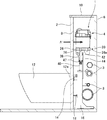
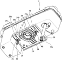
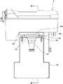
図1は、本発明の一実施形態による便器装置のタンク装置を便器後部のキャビネットパネル内に配置している状態を、キャビネットパネルの取付口を開けた状態で正面から見た正面図であり、図2は本発明の一実施形態による便器装置のタンク装置を便器後部のキャビネットパネル内に隠蔽された状態で配置している状態を、便器装置及びキャビネットパネルの右側側方から見た側面図であり、図3は本発明の一実施形態による便器装置のタンク装置の底部及びタンク装置固定台座ユニットの分解斜視図であり、図4は本発明の一実施形態による便器装置のタンク装置の底部を斜め下方から見た斜視図であり、図5は本発明の一実施形態による便器装置のタンク装置をタンク装置固定台座ユニット上にスライドするように取付ける動作を開始した直後の様子を、タンク装置の斜め下方から見た斜視図である。
以下、本発明の実施形態における説明において、後述する便器装置1を使用する使用者側(便器装置1を使用するために便器装置1の前に立っている使用者側)から見て手前側を前方側(正面側)とし、使用者から見て奥側を後方側(背面側)とし、便器装置1を前方から見て右側を右側とし、前方から見て左側を左側として説明している。
Hereinafter, a toilet device according to an embodiment of the present invention will be described with reference to the accompanying drawings.
FIG. 1 is a front view of a state in which a tank device of a toilet device according to an embodiment of the present invention is disposed in a cabinet panel at the rear of the toilet, as viewed from the front with the mounting opening of the cabinet panel opened, FIG. 2 is a side view of the toilet device tank device according to an embodiment of the present invention, as viewed from the right side of the toilet device and cabinet panel, with the tank device being concealed in the cabinet panel at the rear of the toilet bowl. 3 is an exploded perspective view of the bottom of the tank device of the toilet device and the tank device fixing base unit according to one embodiment of the present invention, and FIG. 4 is a bottom view of the tank device of the toilet device according to one embodiment of the present invention. FIG. 5 is a perspective view seen obliquely from below, and FIG. 5 starts an operation of attaching the tank device of the toilet device according to an embodiment of the present invention so as to slide on the tank device fixed base unit The state immediately after the a perspective view obliquely from below of the tank device.
Hereinafter, in the description of the embodiment of the present invention, the front side as viewed from the user side (the user side standing in front of the
図1及び図2に示すように、本発明の一実施形態による便器装置1は、便器後部のキャビネットパネル2内に隠蔽された状態で配置されるタンク装置4を備えた便器装置である。便器装置1の後部は、正面側のキャビネットパネル2と、背面側の壁面6との間に形成されたキャビネット8の内部空間に配置されている。便器装置1を使用する使用者からは、便器本体12と、キャビネット8の前出形状を構成しているキャビネットパネル2と、頂面パネル10とが見えるのみで、タンク装置4及び給水管等が隠蔽され、使用者に美的感覚を与えるようになっている。
As shown in FIG.1 and FIG.2, the
便器装置1は、キャビネットパネル2の前方側に設置された陶器等からなる便器本体12を有する。便器本体12は、ボウル部(図示せず)内の水の落差による流水作用で汚物を押し流す、いわゆる、洗い落し式の水洗大便器である。便器本体12は、後部に給水口部(給水口)14を有し且つこの給水口部14から供給された洗浄水により自身のボウル部(図示せず)の汚物受け面(図示せず)を洗浄して汚物を排出するようになっている。
なお、便器装置1の便器本体12については、洗い落し式の水洗大便器に限られず、サイホン作用を利用してボウル部内の汚物を吸い込んで排水トラップ管路(図示せず)から一気に外部に排出する、いわゆる、サイホン式便器等、種々の形態の水洗大便器を適用可能である。
The
The
便器本体12は、その後部12aがキャビネットパネル2の裏側に設けられた架台16に便器固定ボルト18を介して固定されている。
なお、本実施形態の便器装置1においては、一例として、便器本体12の背面側がキャビネットパネル2に設置された、いわゆる、壁掛け式の水洗大便器の形態について説明するが、このような形態に限られず、便器本体12の底部が床に設置された、いわゆる、床置き式の水洗大便器のような形態であってもよい。
The toilet
In addition, in the
次にタンク装置4について説明する。
タンク装置4は、便器本体12の後方上方且つキャビネットパネル2の裏側に配置されている。タンク装置4は、水道等の給水源に接続され、且つ便器本体12へ供給する洗浄水を貯水するようになっている。タンク装置4の底部20には、排水口部22が形成されている。タンク装置4は、使用者が壁面等に設けられた操作スイッチ(図示せず)を操作することにより、電気的に内部の装置が駆動され、ジェットポンプ作用により吐水される洗浄水を排水口部22から下方に流出させ、給水管24を経て便器本体12の後方側の導水路(図示せず)に供給されるようになっている。
Next, the
The
本実施形態においては、タンク装置4は、ジェットポンプ作用により洗浄水を便器本体12に供給して洗浄するジェットポンプ式の給水装置である。
なお、便器本体12へ洗浄水を供給する洗浄水源としては、本実施形態で示したジェットポンプ式の給水装置に限定されず、重力給水式の貯水タンクのようなタンク式のものや、水道水の給水圧を直接利用した水道直圧式のものや、フラッシュバルブ式のものや、ポンプの補圧を利用して洗浄水を供給するものであってもよい。
In the present embodiment, the
The cleaning water source for supplying the cleaning water to the
タンク装置4の底部20には、取付固定部26が取付けられて、タンク装置4の底部20を構成している。取付固定部26は、概ね四角形状の外形を有し、且つその内側において壁状に立ち上がる(垂下する)リブ28が配置されている。取付固定部26は、前後方向の幅がタンク装置4の前後方向の幅と概ね同じ長さか又は若干長く形成され、左右方向の幅が、タンク装置4の左右方向の幅と比べてほぼ半分の長さに形成されている。取付固定部26は、中央近傍において円形開口部分30を形成し、この円形開口部分30の内縁において、タンク装置4の底部20の排水口部22の外周を形成する締結部材32により取付固定部26をタンク装置4の底部20に対して締め付けるようにして固定される。締結部材32は、筒状の部材であり且つ上端の外周部分32aが鍔上に拡がるように形成されている。
なお、本実施形態においては、タンク装置4の底部20の排水口23の外周に締結部材32が取付けられている状態で、タンク装置4の底部20の排水口部22を構成している。締結部材32は、排水口23の下端よりもさらに下部まで筒状の流路(排水口部22の流路)を形成している。
An
In the present embodiment, the
便器装置1は、さらに、タンク装置4の底部20の排水口部22の外側に環状に設けられる排水パッキン34と、タンク装置4の底部20を着座するタンク装置固定台座ユニット36であって、タンク装置4の底部20の排水口部22と接続され且つ下方に延びる接続流路38を形成しているタンク装置固定台座ユニット36と、タンク装置固定台座ユニット36の接続流路38の下部と便器本体12の給水口部14とを接続する給水管40と、を備えている。
The
排水パッキン34は、タンク装置4の底部20の排水口部22の外周に配置されている。排水パッキン34は、ゴム等の可撓性の素材で環状に形成され、且つ後述する取付固定部を接続継手に取付けた状態で、タンク装置4の排水口部22と接続流路38との接合部分の周りをシールするように形成されている。排水パッキンは自身が排水口部22を首絞めするようにして、排水口部22の外周に配置された状態となっている。
The drain packing 34 is disposed on the outer periphery of the
タンク装置固定台座ユニット36は、タンク装置4の底部20の排水口部22と給水管40とを接続する接続流路38を形成している接続継手42と、タンク装置4及び接続継手42を支持するタンク支持部材44と、を備えている。
The tank device fixing
接続継手42は、その頂部が概ね四角形状の板状に形成されている。接続継手42は、前後方向の幅がタンク装置4の前後方向の幅と概ね同じ長さに形成され、左右方向の幅が、タンク装置4の左右方向の幅の半分程度の長さに形成されている。接続継手42は、その中央近傍に下方に延びる接続流路38が開口されている。この接続流路38内に排水口部22が配置された状態で、外側に取付けられている排水パッキン34が押しつぶされることにより、接続部分の外周がシールされ、排水口部22内の流路と接続流路38とが連続した流路として水密に連結される。接続継手42の下方に延びる接続流路38の下端には、後述するように給水管40をナット47により連結することができる。
The top of the connection joint 42 is formed in a substantially square plate shape. The connecting joint 42 has a width in the front-rear direction that is substantially the same as a width in the front-rear direction of the
接続継手42は、その頂部の板状部分42aがタンク支持部材44上に配置された状態で固定されている。従って、タンク装置固定台座ユニット36は、タンク支持部材44及び接続継手42が予め固定された状態となっている。
The connection joint 42 is fixed in a state in which the plate-
タンク支持部材44は、自身の下部において、架台16の左右側面に、それぞれネジ止めされて固定されている。タンク支持部材44は、架台16のさらに上方において、タンク装置4及び接続継手42を上部に載せられるような台座を形成している。ここで、便器本体12の後方側のキャビネット8内においては、複数の施設側の配管3(例えば、給水配管、排水配管、雑排水配管、通気配管等)を配置する必要が生じる。従って、これらの施設側の配管3より上方にタンク装置固定台座ユニット36を形成し、タンク装置固定台座ユニット36上にタンク装置4を取付けることとなる。このとき、キャビネット8全体の高さは低く形成されていることが求められているにもかかわらず、タンク装置4は施設側の配管3より上方に配置しなければならないため、タンク装置4を取付口2aの上端に近い位置でも施工できるようにしている。具体的には、タンク装置4を、上方から取付けたり、斜めの姿勢で取付けたりする必要をなくし、ほぼ水平に近い姿勢(取付けた状態の上下姿勢そのままの姿勢)を保ったまま、スライドするように後方に向かって設置できるようになっている。
The
タンク支持部材44は、その上部に取付けられたタンク装置4及び接続継手42を支持し且つ固定する。タンク支持部材44は、タンク装置4を固定する固定ボルト46を開口内に通した状態で前後方向にガイドすることができるガイド口48を形成している。ガイド口48は、U字形状に切り抜かれた開口により形成され且つ前端から後方に向かって直線的に延びる開口を形成している。ガイド口48は、前端に開口され、縦方向に延びた状態の固定ボルト46を、タンク支持部材44の前方側から後方側に、ガイド口48を通した状態でガイドする。
The
つぎに、図3乃至図5に示すように、タンク装置固定台座ユニット36又はタンク装置4に設けられる台座凸部等について説明する
タンク装置固定台座ユニット36の接続継手42は、その上面の平坦面42bから上方に突出した台座凸部42cを備えている。なお、又は、接続継手42は、その上面が下方にくぼまされた台座凹部を備えていてもよい。
さらに、タンク装置4の底部20の取付固定部26は、接続継手42の台座凸部42cと嵌合する凹部26aを備えている。なお、又は、取付固定部26は、接続継手42の下方にくぼまされた台座凹部と嵌合する凸部、を備えていてもよい。
Next, as shown in FIG. 3 to FIG. 5, the pedestal convex portion provided in the tank device fixing
Further, the mounting fixing
接続継手42の台座凸部42cは、円柱形状に形成されたボスを形成している。接続継手42の台座凸部42cは、接続継手42の上面の平坦面42bから垂直上方に立ち上がるように形成されている。図12に示すように、接続継手42の台座凸部42cは、接続継手42の上面の平坦面42bから長さL2だけ上方に突出している。接続継手42の台座凸部42cは、接続継手42の前方部分に配置されている。なお、接続継手42の台座凸部42cは、接続継手42の他の部分に配置されていてもよい。台座凸部42cは、取付固定部26のリブ28が台座凸部42c上をスライドするスライド支持部も構成している。このような構造により、取付固定部26はスライド固定式の取付構造を形成している。
The base
本実施形態においては、台座凸部42c及び凹部26aの組、又は台座凹部及び凸部の組が少なくとも2組以上(2箇所以上)設けられている。
本発明においては、台座凸部42cと、この台座凸部42cと嵌合する凹部26aとの組み合わせにより、凹部26aが台座凸部42cと嵌合することによりタンク装置4の底部20が下降し、排水パッキン34がめくれないように、排水パッキン34を垂直方向に均等に押しつぶすことができる。また、台座凹部と、この台座凹部と嵌合する凸部の組合せによっても、凸部が台座凹部と嵌合することによりタンク装置4の底部20が下降し、排水パッキン34を垂直方向に均等に押しつぶすことができる。
このように、所定の着座位置でのみタンク装置4の底部20が下降するためには、タンク装置4の底部20が所定の着座位置に到達した状態で、台座凸部42c及び凹部26aが、互いに対向した位置に配置される必要がある。従って、台座凸部42c及び凹部26aは組を構成している。このように、タンク装置4の底部20が所定の着座位置に到達した状態で、少なくとも2組以上の複数の組の台座凸部42c及び凹部26aの組が、互いに対向した位置に配置されるように設けられている。同様に、タンク装置4の底部20が所定の着座位置に到達した状態で、少なくとも2組以上の複数の組の台座凹部及び凸部の組が、互いに対向した位置に配置されるように設けられている。
このように台座凸部及び凹部の組又は台座凹部及び凸部の組が2組以上の嵌合構造、すなわち2箇所以上の嵌合構造を形成することにより、タンク装置の底部が、より強固にタンク装置固定台座ユニットに取付けられることができる。また、取付け後に、取付固定部26と接続継手42との間で配置のずれが生じることを防止することができる。また、施工者が取付固定部26と接続継手42との互いの位置関係を正確に取付けることができる。
In the present embodiment, at least two or more (two or more) sets of pedestal
In the present invention, the combination of the pedestal
Thus, in order for the
Thus, the bottom part of the tank apparatus is more firmly formed by forming a pair of pedestal convex portions and concave portions or a pair of pedestal concave portions and convex portions to form two or more fitting structures, that is, two or more fitting structures. It can be attached to the tank device fixed base unit. Further, it is possible to prevent the displacement of the arrangement between the
次に、取付固定部26に形成された凹部26a及びリブ28について説明する。
取付固定部26は、前方部分において、凹部26aを備えている。取付固定部26は、高さ方向に所定の長さ(幅)を有しており、この凹部26aが、取付固定部26の下向きの内側底面26bから長さL1だけ下方に突出した部分を下端26cとし、これより上方側に凹むような円筒形状の空間を形成している。別の言い方によれば、凹部26aは、円筒形状の台座凸部42cを内部に受け入れることができるような円筒形状の内側空間を形成するような凹部26aとして形成されている。凹部26aは、「Ω」オメガ字形状のように、一部が前端において開口されているような内側空間を形成していてもよい。なお、凹部26aは、例えば、U字形状、円筒形状のような台座凸部を受け入れることができるような他の形状に形成されていてもよい。
図3乃至図5に示すように、凹部26aの下端26cは、上述のように取付固定部26の内側底面よりも下方側に形成されている。逆に、凹部26aの上端26dは、取付固定部26の内側底面26bよりも上方側に形成されている。
Next, the recessed
The
As shown in FIGS. 3 to 5, the
図4に示すように、取付固定部26のリブ28は、取付固定部26の内側底面26bから長さL1だけ下方に突出している。すなわち、図4及び図5に示すように、リブ28の内側底面26bから下方へ突出する長さL1と凹部26aの内側底面26bから下方へ突出する長さL1とが同じ長さに形成されている。従って、台座凸部42c上をリブ28がスライドされ且つ下端26c上までそのスライド動作を継続して、台座凸部42cが凹部26aの中心まで一連の動きとしてスライドされることができる。
リブ28は、取付固定部26の中央近傍(例えば、タンク装置4の前後方向中央近傍の固定ボルト46近傍の位置))から前部の凹部26aまで、前後方向に延びるように形成されている。また、リブ28は、取付固定部26の中央近傍から前部の凹部26aまで、同じ所定の高さ(内側底面26bから下端26cまでの長さL1)に形成されている。
As shown in FIG. 4, the
The
取付固定部26の後端の垂下壁26eは、リブ28等の下方へ突出する長さL1よりも長い長さまで下方に突出している。垂下壁26eは、取付固定部26の後端において左右方向に延びる一枚の縦壁を形成している。取付固定部26が接続継手42に取付けられる際には、垂下壁26eは、接続継手42の後端面42dと平行に配置される。従って、垂下壁26eと後端面42dとを平行に接するようにすることで、取付固定部26を、接続継手42に対して正確な位置に位置決めさせることができ、さらに、取付固定部26と、接続継手42との角度のずれを修正させることもできる。また、垂下壁26eが後端面42dに引っ掛るわずかな抵抗感、引掛り感、又は垂下壁26eと後端面42dとが面と面によりフィットするフィット感等の感触が施工者に伝わるため、施工者は垂下壁26e側が目視できない又は目視しにくい状況であったとしても、垂下壁26e側の状態を手の間隔等により把握し、タンク装置4の取付けをしやすくすることができる。
The hanging
取付固定部26は、さらに、リブ28の左右方向外側の位置に、リブ28と平行に形成されたずれ防止リブ29を備えている。ずれ防止リブ29は、リブ28と前後方向に平行に延びる壁面を形成している。ずれ防止リブ29は、リブ28から、台座凸部42cの半径の長さよりもわずかに外側に形成されている。よって、台座凸部42c上をスライドするリブ28が左右方向にずれる場合、又は接続継手42が左右方向にずれる場合に、ずれ防止リブ29が台座凸部42cと当接することになり、取付固定部26が左右方向にずれることを防止することができる。
The
つぎに、図5〜図12により、本発明の一実施形態による便器装置1のタンク装置4をタンク装置固定台座ユニット36に取付ける動作を説明する。
図5は本発明の一実施形態による便器装置のタンク装置をタンク装置固定台座ユニット上にスライドするように取付ける動作を開始した直後の様子を、タンク装置の斜め下方から見た斜視図であり、図6は本発明の一実施形態による便器装置のタンク装置をタンク装置固定台座ユニット上にスライドするように取付ける動作を開始した直後の様子を、タンク装置の正面側から見た正面図であり、図7は図6のVII−VII線に沿って見た断面図であり、図8は本発明の一実施形態による便器装置のタンク装置をタンク装置固定台座ユニット上にスライドするように取付ける動作において、垂下壁が接続継手の後端に到達し且つ凹部26aが台座凸部42cと嵌合して沈み込むように下降できる位置に到達した状態の様子を、タンク装置の正面側から見た正面図であり、図9は図8のIX−IX線に沿って見た断面図であり、図10は本発明の一実施形態による便器装置のタンク装置をタンク装置固定台座ユニット上にスライドするように取付ける動作において、取付固定部の凹部が台座凸部と嵌合して沈み込むように下降した状態を、タンク装置の正面側から見た正面図であり、図11は図10のXI−XI線に沿って見た断面図であり、図12は本発明の一実施形態による便器装置のタンク装置をタンク装置固定台座ユニット上にスライドするように取付ける動作において、台座凸部上をリブが後方に滑るように移動しながらスライドされ、凹部が台座凸部上に至る様子を拡大して示している部分拡大図である。
Next, an operation of attaching the
FIG. 5 is a perspective view of a state immediately after starting the operation of mounting the tank device of the toilet device according to the embodiment of the present invention so as to slide on the tank device fixing pedestal unit, as viewed from obliquely below the tank device, FIG. 6 is a front view of a state immediately after starting the operation of attaching the tank device of the toilet device according to the embodiment of the present invention so as to slide on the tank device fixing pedestal unit, as viewed from the front side of the tank device, 7 is a cross-sectional view taken along the line VII-VII in FIG. 6, and FIG. 8 is an operation for slidingly mounting the tank device of the toilet device according to the embodiment of the present invention on the tank device fixed base unit. The state in which the drooping wall has reached the rear end of the connection joint and the
施設側において、キャビネット8及びそのキャビネットパネル2は据え付けられており、便器装置1の施工者は、例えば、キャビネットパネル2の正面側に形成された取付口2aからタンク装置4を施工することとなる。例えば、図1に示すように、キャビネットパネル2の一部として取付口2aの内側部分が取り外し可能に形成されており、取付口2aの内側部分を取り外した状態で、取付口2aからタンク装置4を施工する。施工後に取付口2aの内側部分を取付けることにより、便器装置1を使用する使用者には、正面側にキャビネットパネル2のみがあるように見えるようにキャビネット8が形成されている。このように、施工者が、比較的狭い限られたスペースにおいて、タンク装置4を上方からタンク装置固定台座ユニット36に取付けにくい場合又は取付けることができない場合において、タンク装置4を正面からタンク装置固定台座ユニット36上にスライドするように取付けることができることを以下説明する。
On the facility side, the
図2に示すように、最初に、キャビネットパネル2の裏側において、架台16を床面に固定する。次に、タンク支持部材44の下部44aを架台16の上部の左右側面にねじ止めすることにより固定する。接続継手42がタンク支持部材44の上面上に載せられた状態でタンク支持部材44に対して固定される。また、接続継手42は、その接続流路38の下端を下流側の給水管40とナット47により接続する。便器本体12は、キャビネットパネル2の前面側に配置され、キャビネットパネル2の裏側から延びる便器固定ボルト18により架台16と固定される。
As shown in FIG. 2, first, the
図4に示すように、タンク装置4は、タンク装置4の便器洗浄のために必要な機能部(給水装置、排水装置、操作装置等)を予め組立てた状態とされている。タンク装置4の底部には、取付固定部26が取付けられ、締結部材32により取付固定部26をタンク装置4の底部に対して締め付けるようにして固定されている。また、排水パッキン34がタンク装置4の底部20の排水口部22の外周に配置されている。排水パッキン34は自身が首絞めするようにして、落下せず、排水口部22の外周に嵌まった状態となっている。固定ボルト46はその上端が取付固定部26に取付けられ且つその下端が未だ取付けられていない状態で、取付固定部26から下方にぶら下がっている。
As shown in FIG. 4, the
施工者が、上述のような状態まで各部材を取付けたタンク装置4のユニットを、便器後部のキャビネットパネル2内に隠蔽された状態で配置するため、キャビネットパネル2の正面側に形成された取付口2aからタンク装置4固定台座ユニットに取付ける。
図5乃至図7に示すように、具体的には、タンク装置4の底部20の取付固定部26のリブ28をタンク装置固定台座ユニット36の接続継手42の台座凸部42c上に載せるように配置し、図1に示すようなキャビネットパネル2の正面側に形成された取付口2aから、キャビネットパネル2後方の所定の着座位置まで、図2の矢印A1に示すように、取付固定部26が取付けられた状態のタンク装置4を前後方向にスライドさせることができる。
An installation formed on the front side of the
Specifically, as shown in FIGS. 5 to 7, the
このとき、図7に示すように、台座凸部42c上をリブ28が後方に滑るように移動しながらスライドされる。取付固定部26の後端の垂下壁26eは、接続継手42上を後方にスライドされる。タンク装置4全体は概ね水平に後方に向かってスライドされる。取付固定部26の固定ボルト46は、ガイド口48に沿って後方にスライドされる。取付固定部26の固定ボルト46は、ガイド口48に沿って前後方向に自由に移動でき、さらに、ガイド口48によって左右方向に移動してしまうことを防止される。施工者は、台座凸部42cと、リブ28又は凹部26aとの位置、又は、固定ボルト46とガイド口48との位置を容易に視認しながら比較的簡単且つ正確な位置にタンク装置4を取付けることができる。
At this time, as shown in FIG. 7, the
図8及び図9に示すように、台座凸部42c上をリブ28が後方に移動しながらスライドされ、台座凸部42cが凹部26aと対向する位置(所定の着座位置)に到達するとき、垂下壁26eが接続継手42の後端面42dを超える位置に到達する。垂下壁26eが接続継手42の後端に到達するとき、垂下壁26eが接続継手42の後端面42dに掛かるようにすることができ、取付固定部26を正確に位置決めすることができる。また、台座凸部42cが凹部26aと対向する位置に存在するか否かを、施工者が正面側から容易に視認することができ、タンク装置4の底部20を、タンク装置固定台座ユニット36に容易に取付けることができる。
凹部26aが台座凸部42cと嵌合して沈み込むように下降できる位置、すなわちタンク装置4の底部20の所定の着座位置に到達すると、タンク装置4の底部20の下降が開始できるようになる。
As shown in FIGS. 8 and 9, when the
When the
図12においては、台座凸部42c上をリブ28が後方に滑るように移動しながらスライドされ、凹部26aが台座凸部42c上に至る様子を拡大して示している。
取付固定部26のリブ28は、取付固定部26の内側底面26bから長さL1だけ下方に突出している。また、接続継手42の台座凸部42cは、接続継手42の上面の平坦面42bから長さL2だけ上方に突出している。従って、取付固定部26の内側底面26bから接続継手42の平坦面42bまでの長さがL1+L2の長さになっている。ここで、排水パッキン34は、取付固定部26の内側底面26bから長さL3だけ下方に突出している。さらに、排水口部22(締結部材32)は、取付固定部26の内側底面26bから長さL4だけ下方に突出している。ここで、L3の長さはL1+L2の長さよりも短く、L4の長さはL1+L2の長さよりも短くなっている。締結部材32は、排水パッキン34よりもやや下方まで延びるように形成されているので、L3よりもL4の方が長く形成されている。
従って、台座凸部42c(凹部26a)上をリブ28がスライドしている最中において、排水パッキン34及び排水口部22のいずれも接続継手42の平坦面42bに接触することがない。従って、排水パッキン34が平坦面42bに接触し、横方向の力を受けてめくれることを防ぐことができる。
In FIG. 12, the state in which the
The
Therefore, neither the drainage packing 34 nor the
図10及び図11に示すように、取付固定部26の凹部26aが台座凸部42cと嵌合して沈み込むように下降できる。すなわち、取付固定部26が接続継手42上に被さるようにして、取付固定部26と接続継手42とが組み合わされる。取付固定部26を有するタンク装置4が、タンク装置固定台座ユニット36の接続継手42上に、下降しながら着座するとき、タンク装置4の底部20の排水口部22に取付けられていた排水パッキン34も下降しながら接続継手42の平坦面42b上に均等に押し広げられる。排水パッキン34は押しつぶされた状態でタンク装置4の排水口部22と接続流路38との接合部分の周りをシールする。このように、排水パッキン34は下降しながら押しつぶされるので、排水パッキン34が横方向に移動されることにより排水パッキン34がめくれること又はよれたりすることを防止することができる。
従って、比較的狭い施工スペースにおいて、タンク装置4をキャビネットパネル2の正面側に形成された取付口2aから後方にスライドするように取付ける場合においても、タンク装置4の排水口部22と接続流路38との接合部分の周りをシールする排水パッキン34がめくれないように適切に配置することができる。よって、タンク装置4の底部20が、タンク装置4の排水口部22と接続流路38との接合部分の外側を排水パッキンにより水密にシールした状態で、タンク装置固定台座ユニット36に取付けられることができる。
As shown in FIGS. 10 and 11, the
Therefore, even when the
上述した本発明の一実施形態による便器装置1によれば、タンク装置4の底部20をタンク装置固定台座ユニット36上で、キャビネットパネル2の正面側に形成された取付口2aからキャビネットパネル2後方の所定の着座位置まで前後方向にスライドさせることができ、タンク装置4の底部20が所定の着座位置に到達した状態で、台座凸部42cと嵌合する凹部26a、又は台座凹部と嵌合する凸部の組合せのいずれかの構造により、タンク装置4の底部20がタンク装置固定台座ユニット36上に沈み込むように下降され、排水パッキン34を下方に押圧することとなるので、排水パッキン34のめくれを防止することができ、排水パッキン34のめくれによる漏水の発生を防止することができる。
従って、比較的狭い施工スペースであっても、便器後部のキャビネットパネル2内に隠蔽された状態で配置されるタンク装置4を、キャビネットパネル2の正面側に形成された取付口2aからタンク装置固定台座ユニット36に取付けることができると共に、取付けの際の排水パッキン34のめくれを防止することができ、タンク装置4の底部20が、タンク装置4の排水口部22と接続流路38との接合部分の外側を排水パッキン34によりシールした状態で、タンク装置固定台座ユニット36に取付けられることができる。
According to the
Accordingly, even in a relatively narrow construction space, the
また、本実施形態による便器装置1によれば、台座凸部42cと嵌合する凹部26a、又は台座凹部と嵌合する凸部の組合せのいずれかの構造を、キャビネットパネル2の正面側に形成された取付口2aから容易に目視することができるため、タンク装置4の底部20をタンク装置固定台座ユニット36上で、所定の着座位置まで容易にスライドさせることができ、タンク装置4の底部20を、タンク装置固定台座ユニット36に容易に取付けることができる。
Further, according to the
さらに、本実施形態による便器装置1によれば、タンク装置4の底部20を接続継手42の台座凸部42cの上で、キャビネットパネル2の正面側に形成された取付口2aからキャビネットパネル2後方の所定の着座位置まで前後方向にスライドさせることができ、タンク装置4の底部20が所定の着座位置に到達した状態で、台座凸部42cと嵌合する凹部26aの構造により、タンク装置4の底部20が接続継手42上に沈み込むように下降され、排水パッキン34を下方に押圧することとなるので、排水パッキン34のめくれを防止することができ、排水パッキン34のめくれによる漏水の発生を防止することができる。従って、比較的狭い施工スペースであっても、便器後部のキャビネットパネル2内に隠蔽された状態で配置されるタンク装置4を、キャビネットパネル2の正面側に形成された取付口2aからタンク装置固定台座ユニット36の接続継手42上に取付けることができると共に、取付けの際の排水パッキン34のめくれを防止することができ、タンク装置4の底部20が、タンク装置4の排水口部22と接続流路38との接合部分の外側を排水パッキン34によりシールした状態で、タンク装置固定台座ユニット36に取付けられることができる。また、タンク装置4の底部20の排水口部22と、接続流路38を有する接続継手42との位置合わせを容易に行うことができる。
Furthermore, according to the
また、本実施形態による便器装置1によれば、施工取付け時に、タンク装置4の底部20の排水口部22が排水パッキン34よりも下方まで突出しており、且つ排水口部22が内側底面26bから突出する長さL4は、接続継手42の台座凸部42cが接続継手42の平坦面42bから上方に突出する長さL2と、タンク装置4の底部20のリブ28及び凹部26aが内側底面26bから下方に突出する長さL1との和より小さい長さである。よって、タンク装置4をスライドさせて取付けるときに、排水口部22が接続継手42と接触しないように構成されている。また、排水口部22は排水パッキン34よりも下方まで突出しているので、排水パッキン34が接続継手42と接触することを防止することができ、スライド動作中の排水パッキン34のめくれを防止することができ、排水パッキン34のめくれによる漏水の発生を防止することができる。
Further, according to the
また、本実施形態による便器装置1によれば、タンク装置4の底部20が、台座凸部42c及び凹部26aの組又は台座凹部及び凸部の組のいずれかの2組以上の嵌合構造、すなわち2箇所以上の嵌合構造により、より強固にタンク装置固定台座ユニット36に取付けられることができる。
Further, according to the
また、本実施形態による便器装置1によれば、タンク装置4を、その固定ボルト46をガイド口48の開口内に通した状態で前後方向にガイドすることができるため、タンク装置4を、タンク装置固定台座ユニット36上で所定の着座位置まで容易に前後方向にスライドさせることができる。
Further, according to the
また、本実施形態による便器装置1によれば、施工者が目視することが難しいキャビネットパネル2の奥側において、垂下壁の前面をタンク装置固定台座ユニット36に当接させた状態とし、タンク装置4の底部20をタンク装置固定台座ユニット36上で所定の着座位置に容易且つ正確に位置決めすることができる。
Further, according to the
1 便器装置
2 キャビネットパネル
2a 取付口
3 配管
4 タンク装置
6 壁面
8 キャビネット
10 頂面パネル
12 便器本体
12a 後部
14 給水口部
16 架台
18 便器固定ボルト
20 底部
22 排水口部
23 排水口
24 給水管
26 取付固定部
26a 凹部
26b 内側底面
26c 下端
26d 上端
26e 垂下壁
28 リブ
29 防止リブ
30 円形開口部分
32 締結部材
32a 外周部分
34 排水パッキン
36 タンク装置固定台座ユニット
38 接続流路
40 給水管
42 接続継手
42a 板状部分
42b 平坦面
42c 台座凸部
42d 後端面
44 タンク支持部材
44a 下部
46 固定ボルト
47 ナット
48 ガイド口
A1 矢印
DESCRIPTION OF
Claims (7)
後部に給水口を有し且つこの給水口から供給された洗浄水により汚物を排出する便器本体と、
前記便器本体へ供給する洗浄水を貯水するタンク装置と、
前記タンク装置の底部の排水口の外側に環状に設けられる排水パッキンと、
前記タンク装置の底部を着座するタンク装置固定台座ユニットであって、前記タンク装置の前記底部の前記排水口と接続される接続流路を形成している前記タンク装置固定台座ユニットと、
前記タンク装置固定台座ユニットの下部と前記便器本体の前記給水口とを接続する給水管とを有し、
前記タンク装置固定台座ユニットは、上方に突出した台座凸部又は下方にくぼまされた台座凹部を備え、
前記タンク装置の前記底部は、前記上方に突出した台座凸部と嵌合する凹部、又は前記下方にくぼまされた台座凹部と嵌合する凸部、を備え、
前記タンク装置の前記底部又は前記タンク装置固定台座ユニットは、前記タンク装置の前記底部を前記タンク装置固定台座ユニット上で、前記キャビネットパネルの正面側に形成された取付口から前記キャビネットパネル後方の所定の着座位置まで前後方向にスライドさせることができるリブを備え、
前記タンク装置の前記底部が所定の着座位置に到達した状態で、前記台座凸部と嵌合する前記凹部、又は前記台座凹部と嵌合する前記凸部の組合せのいずれかの構造により、前記タンク装置の前記底部が前記タンク装置固定台座ユニット上に沈み込むように下降され、前記排水パッキンを下方に押圧することとなり、前記タンク装置の前記底部が、前記タンク装置の前記排水口と前記接続流路との接合部分の外側を前記排水パッキンによりシールした状態で、前記タンク装置固定台座ユニットに取付けられることを特徴とする便器装置。 A toilet device comprising a tank device arranged in a concealed state in a cabinet panel at the rear of the toilet,
A toilet body having a water supply port at the rear and discharging filth by the wash water supplied from the water supply port;
A tank device for storing wash water to be supplied to the toilet body;
Drain packing provided in an annular shape outside the drain port at the bottom of the tank device;
A tank device fixed pedestal unit for seating the bottom of the tank device, the tank device fixed pedestal unit forming a connection channel connected to the drain port of the bottom of the tank device;
A water supply pipe connecting the lower part of the tank device fixed base unit and the water supply port of the toilet body,
The tank device fixed pedestal unit includes a pedestal convex portion protruding upward or a pedestal concave portion recessed downward,
The bottom portion of the tank device includes a concave portion that fits with the pedestal convex portion protruding upward, or a convex portion that fits with the pedestal concave portion recessed downward.
The bottom of the tank device or the tank device fixing pedestal unit is a predetermined rear side of the cabinet panel from an attachment port formed on the front side of the cabinet panel on the tank device fixing pedestal unit. Equipped with a rib that can be slid back and forth to the seating position of
In the state in which the bottom portion of the tank device has reached a predetermined seating position, the tank is configured by any one of the concave portion fitted to the pedestal convex portion or the combination of the convex portions fitted to the pedestal concave portion. The bottom portion of the device is lowered so as to sink onto the tank device fixed pedestal unit, and the drainage packing is pressed downward, and the bottom portion of the tank device is connected to the drain port of the tank device and the connection flow. The toilet device is attached to the tank device fixing pedestal unit in a state in which an outside of a joint portion with a road is sealed by the drainage packing.
前記タンク装置の前記底部は、前方部分において、前記台座凸部と嵌合する前記凹部、又は前記台座凹部と嵌合する前記凸部、を備えている、請求項1に記載の便器装置。 The tank device fixed pedestal unit is provided with the pedestal convex portion or the pedestal concave portion in the front portion,
The toilet apparatus according to claim 1, wherein the bottom portion of the tank device includes the concave portion that fits with the pedestal convex portion or the convex portion that fits with the pedestal concave portion at a front portion.
前記タンク装置の前記底部の前記排水口と前記給水管とを接続する前記接続流路を形成している接続継手と、
前記タンク装置及び前記接続継手を支持するタンク支持部材と、
を備え、
前記接続継手が、上方に突出した前記台座凸部を備え、
前記タンク装置の前記底部の前記リブを前記接続継手の前記台座凸部の上で、前記キャビネットパネルの正面側に形成された取付口から前記キャビネットパネル後方の所定の着座位置まで前後方向にスライドさせることができ、前記タンク装置の前記底部が所定の着座位置に到達した状態で、前記台座凸部と嵌合する前記凹部の構造により、前記タンク装置の前記底部が前記接続継手上に沈み込むように下降され、前記排水パッキンを下方に押圧することとなり、前記タンク装置の前記底部が、前記タンク装置の前記排水口と前記接続流路との接合部分の外側を前記排水パッキンによりシールした状態で、前記接続継手に取付けられる請求項1又は2に記載の便器装置。 The tank device fixed base unit is
A connection joint forming the connection flow path for connecting the drain outlet of the bottom of the tank device and the water supply pipe;
A tank support member that supports the tank device and the connection joint;
With
The connection joint includes the pedestal projection protruding upward,
The rib at the bottom of the tank device is slid in the front-rear direction from the mounting opening formed on the front side of the cabinet panel to a predetermined seating position behind the cabinet panel on the pedestal convex portion of the connection joint. The bottom portion of the tank device sinks onto the connection joint by the structure of the concave portion that fits with the base convex portion when the bottom portion of the tank device reaches a predetermined seating position. The drainage packing is pushed downward, and the bottom portion of the tank device seals the outside of the joint portion between the drainage port of the tank device and the connection flow path with the drainage packing. The toilet device according to claim 1, wherein the toilet device is attached to the connection joint.
前記タンク装置の前記底部の前記排水口は、前記タンク装置をスライドさせて取付けるために前記排水口の外側に前記排水パッキンが取付けられている状態において、前記排水パッキンよりも下方まで突出するような長さを有するように形成され、
前記タンク装置の前記底部の前記排水口が前記底部から突出する長さは、前記接続継手の前記台座凸部が前記接続継手から上方に突出する長さと、前記タンク装置の前記底部の前記リブが前記底部から下方に突出する長さとの和より小さい長さとされている請求項3に記載の便器装置。 The bottom portion of the tank device is front and back from a mounting opening formed on the front side of the cabinet panel to a predetermined seating position behind the cabinet panel on the pedestal convex portion of the connection joint. It has a rib that protrudes downward so that it can slide in the direction,
The drainage port at the bottom of the tank device protrudes below the drainage packing in a state where the drainage packing is attached to the outside of the drainage port for slidingly mounting the tank device. Formed to have a length,
The length of the drainage port of the bottom of the tank device protruding from the bottom is such that the pedestal projection of the connection joint protrudes upward from the connection joint, and the rib of the bottom of the tank device is The toilet device according to claim 3, wherein the toilet device has a length smaller than a sum of the length protruding downward from the bottom portion.
Priority Applications (1)
| Application Number | Priority Date | Filing Date | Title |
|---|---|---|---|
| JP2015191737A JP6579373B2 (en) | 2015-09-29 | 2015-09-29 | Toilet device |
Applications Claiming Priority (1)
| Application Number | Priority Date | Filing Date | Title |
|---|---|---|---|
| JP2015191737A JP6579373B2 (en) | 2015-09-29 | 2015-09-29 | Toilet device |
Publications (2)
| Publication Number | Publication Date |
|---|---|
| JP2017066673A JP2017066673A (en) | 2017-04-06 |
| JP6579373B2 true JP6579373B2 (en) | 2019-09-25 |
Family
ID=58491895
Family Applications (1)
| Application Number | Title | Priority Date | Filing Date |
|---|---|---|---|
| JP2015191737A Active JP6579373B2 (en) | 2015-09-29 | 2015-09-29 | Toilet device |
Country Status (1)
| Country | Link |
|---|---|
| JP (1) | JP6579373B2 (en) |
Families Citing this family (3)
| Publication number | Priority date | Publication date | Assignee | Title |
|---|---|---|---|---|
| JP6861667B2 (en) * | 2018-04-27 | 2021-04-21 | 株式会社Lixil | Toilet bowl device |
| JP2019190191A (en) * | 2018-04-27 | 2019-10-31 | 株式会社Lixil | Toilet bowl unit |
| JP7193785B2 (en) * | 2020-06-02 | 2022-12-21 | Toto株式会社 | flush toilet |
Family Cites Families (6)
| Publication number | Priority date | Publication date | Assignee | Title |
|---|---|---|---|---|
| DE2653363A1 (en) * | 1976-11-24 | 1978-06-01 | Chloride Group Ltd | Water closet with flushing tank behind cover and panel - has part of panel removable to gain access to forward movable tank |
| JPH057760U (en) * | 1991-07-12 | 1993-02-02 | 株式会社イナツクス | Low tank |
| JP3637744B2 (en) * | 1996-10-31 | 2005-04-13 | 東陶機器株式会社 | Toilet case and its assembly method |
| JPH1161935A (en) * | 1997-08-25 | 1999-03-05 | Inax Corp | Mounted structure of cover box |
| JP2004285670A (en) * | 2003-03-20 | 2004-10-14 | Toto Ltd | Toilet bowl |
| JP6066458B2 (en) * | 2013-06-14 | 2017-01-25 | Toto株式会社 | Toilet device |
-
2015
- 2015-09-29 JP JP2015191737A patent/JP6579373B2/en active Active
Also Published As
| Publication number | Publication date |
|---|---|
| JP2017066673A (en) | 2017-04-06 |
Similar Documents
| Publication | Publication Date | Title |
|---|---|---|
| US10612223B2 (en) | Toilet pan body and its method for manufacturing | |
| WO2001040589A1 (en) | Tankless toilet, western style flush toilet, private part washing device, and spud for flush toilet | |
| US10151091B2 (en) | Toilet apparatus | |
| JP6579373B2 (en) | Toilet device | |
| JP6691659B2 (en) | Flush toilet | |
| JP2014173390A (en) | Toilet bowl installation structure | |
| JP3189917U (en) | Manhole-connected disaster toilet set | |
| JP6649080B2 (en) | Connection structure of hand washing spout pipe | |
| JP2010031570A (en) | Drainage connection structure of flush toilet bowl and washbasin | |
| KR101243894B1 (en) | Connection structure for trap and drain pipe | |
| JP7179258B2 (en) | bowl unit | |
| JP6351065B2 (en) | Drain socket | |
| JP2011111780A (en) | Drainage structure | |
| JP4278459B2 (en) | Piping fixing structure for bathtub with wash basin | |
| JP5685729B2 (en) | Hand washing machine | |
| JP2019148135A (en) | Water closet device | |
| JP5013947B2 (en) | Toilet fixing device | |
| JP2019005058A (en) | Filth sink unit | |
| EP2963196A1 (en) | Drain device with a non-circular inlet hole. | |
| JP6879085B2 (en) | casing | |
| JP2010111996A (en) | Toilet unit | |
| JP6659207B2 (en) | Flush toilet | |
| JP2000234374A5 (en) | ||
| JP2012241453A (en) | Toilet bowl device | |
| JP2016108773A (en) | Faucet device |
Legal Events
| Date | Code | Title | Description |
|---|---|---|---|
| RD04 | Notification of resignation of power of attorney |
Free format text: JAPANESE INTERMEDIATE CODE: A7424 Effective date: 20170427 |
|
| A621 | Written request for application examination |
Free format text: JAPANESE INTERMEDIATE CODE: A621 Effective date: 20180914 |
|
| A977 | Report on retrieval |
Free format text: JAPANESE INTERMEDIATE CODE: A971007 Effective date: 20190722 |
|
| TRDD | Decision of grant or rejection written | ||
| A01 | Written decision to grant a patent or to grant a registration (utility model) |
Free format text: JAPANESE INTERMEDIATE CODE: A01 Effective date: 20190801 |
|
| A61 | First payment of annual fees (during grant procedure) |
Free format text: JAPANESE INTERMEDIATE CODE: A61 Effective date: 20190814 |
|
| R150 | Certificate of patent or registration of utility model |
Ref document number: 6579373 Country of ref document: JP Free format text: JAPANESE INTERMEDIATE CODE: R150 |