JP6576331B2 - Roller type rocker arm - Google Patents
Roller type rocker arm Download PDFInfo
- Publication number
- JP6576331B2 JP6576331B2 JP2016514877A JP2016514877A JP6576331B2 JP 6576331 B2 JP6576331 B2 JP 6576331B2 JP 2016514877 A JP2016514877 A JP 2016514877A JP 2016514877 A JP2016514877 A JP 2016514877A JP 6576331 B2 JP6576331 B2 JP 6576331B2
- Authority
- JP
- Japan
- Prior art keywords
- roller
- rocker arm
- sliding
- ring roller
- peripheral surface
- Prior art date
- Legal status (The legal status is an assumption and is not a legal conclusion. Google has not performed a legal analysis and makes no representation as to the accuracy of the status listed.)
- Active
Links
Images


Classifications
-
- F—MECHANICAL ENGINEERING; LIGHTING; HEATING; WEAPONS; BLASTING
- F01—MACHINES OR ENGINES IN GENERAL; ENGINE PLANTS IN GENERAL; STEAM ENGINES
- F01L—CYCLICALLY OPERATING VALVES FOR MACHINES OR ENGINES
- F01L1/00—Valve-gear or valve arrangements, e.g. lift-valve gear
- F01L1/12—Transmitting gear between valve drive and valve
- F01L1/18—Rocking arms or levers
- F01L1/185—Overhead end-pivot rocking arms
-
- F—MECHANICAL ENGINEERING; LIGHTING; HEATING; WEAPONS; BLASTING
- F01—MACHINES OR ENGINES IN GENERAL; ENGINE PLANTS IN GENERAL; STEAM ENGINES
- F01L—CYCLICALLY OPERATING VALVES FOR MACHINES OR ENGINES
- F01L1/00—Valve-gear or valve arrangements, e.g. lift-valve gear
- F01L1/02—Valve drive
- F01L1/04—Valve drive by means of cams, camshafts, cam discs, eccentrics or the like
- F01L1/047—Camshafts
- F01L1/053—Camshafts overhead type
-
- F—MECHANICAL ENGINEERING; LIGHTING; HEATING; WEAPONS; BLASTING
- F01—MACHINES OR ENGINES IN GENERAL; ENGINE PLANTS IN GENERAL; STEAM ENGINES
- F01L—CYCLICALLY OPERATING VALVES FOR MACHINES OR ENGINES
- F01L1/00—Valve-gear or valve arrangements, e.g. lift-valve gear
- F01L1/12—Transmitting gear between valve drive and valve
- F01L1/18—Rocking arms or levers
-
- F—MECHANICAL ENGINEERING; LIGHTING; HEATING; WEAPONS; BLASTING
- F16—ENGINEERING ELEMENTS AND UNITS; GENERAL MEASURES FOR PRODUCING AND MAINTAINING EFFECTIVE FUNCTIONING OF MACHINES OR INSTALLATIONS; THERMAL INSULATION IN GENERAL
- F16C—SHAFTS; FLEXIBLE SHAFTS; ELEMENTS OR CRANKSHAFT MECHANISMS; ROTARY BODIES OTHER THAN GEARING ELEMENTS; BEARINGS
- F16C33/00—Parts of bearings; Special methods for making bearings or parts thereof
- F16C33/02—Parts of sliding-contact bearings
- F16C33/04—Brasses; Bushes; Linings
- F16C33/06—Sliding surface mainly made of metal
- F16C33/10—Construction relative to lubrication
- F16C33/1025—Construction relative to lubrication with liquid, e.g. oil, as lubricant
- F16C33/103—Construction relative to lubrication with liquid, e.g. oil, as lubricant retained in or near the bearing
-
- F—MECHANICAL ENGINEERING; LIGHTING; HEATING; WEAPONS; BLASTING
- F01—MACHINES OR ENGINES IN GENERAL; ENGINE PLANTS IN GENERAL; STEAM ENGINES
- F01L—CYCLICALLY OPERATING VALVES FOR MACHINES OR ENGINES
- F01L1/00—Valve-gear or valve arrangements, e.g. lift-valve gear
- F01L1/20—Adjusting or compensating clearance
-
- F—MECHANICAL ENGINEERING; LIGHTING; HEATING; WEAPONS; BLASTING
- F01—MACHINES OR ENGINES IN GENERAL; ENGINE PLANTS IN GENERAL; STEAM ENGINES
- F01L—CYCLICALLY OPERATING VALVES FOR MACHINES OR ENGINES
- F01L1/00—Valve-gear or valve arrangements, e.g. lift-valve gear
- F01L1/02—Valve drive
- F01L1/04—Valve drive by means of cams, camshafts, cam discs, eccentrics or the like
- F01L1/047—Camshafts
- F01L1/053—Camshafts overhead type
- F01L2001/0535—Single overhead camshafts [SOHC]
-
- F—MECHANICAL ENGINEERING; LIGHTING; HEATING; WEAPONS; BLASTING
- F01—MACHINES OR ENGINES IN GENERAL; ENGINE PLANTS IN GENERAL; STEAM ENGINES
- F01L—CYCLICALLY OPERATING VALVES FOR MACHINES OR ENGINES
- F01L2301/00—Using particular materials
-
- F—MECHANICAL ENGINEERING; LIGHTING; HEATING; WEAPONS; BLASTING
- F01—MACHINES OR ENGINES IN GENERAL; ENGINE PLANTS IN GENERAL; STEAM ENGINES
- F01L—CYCLICALLY OPERATING VALVES FOR MACHINES OR ENGINES
- F01L2305/00—Valve arrangements comprising rollers
-
- F—MECHANICAL ENGINEERING; LIGHTING; HEATING; WEAPONS; BLASTING
- F01—MACHINES OR ENGINES IN GENERAL; ENGINE PLANTS IN GENERAL; STEAM ENGINES
- F01L—CYCLICALLY OPERATING VALVES FOR MACHINES OR ENGINES
- F01L2305/00—Valve arrangements comprising rollers
- F01L2305/02—Mounting of rollers
-
- F—MECHANICAL ENGINEERING; LIGHTING; HEATING; WEAPONS; BLASTING
- F01—MACHINES OR ENGINES IN GENERAL; ENGINE PLANTS IN GENERAL; STEAM ENGINES
- F01L—CYCLICALLY OPERATING VALVES FOR MACHINES OR ENGINES
- F01L2800/00—Methods of operation using a variable valve timing mechanism
- F01L2800/18—Testing or simulation
-
- F—MECHANICAL ENGINEERING; LIGHTING; HEATING; WEAPONS; BLASTING
- F01—MACHINES OR ENGINES IN GENERAL; ENGINE PLANTS IN GENERAL; STEAM ENGINES
- F01L—CYCLICALLY OPERATING VALVES FOR MACHINES OR ENGINES
- F01L2810/00—Arrangements solving specific problems in relation with valve gears
- F01L2810/02—Lubrication
-
- F—MECHANICAL ENGINEERING; LIGHTING; HEATING; WEAPONS; BLASTING
- F01—MACHINES OR ENGINES IN GENERAL; ENGINE PLANTS IN GENERAL; STEAM ENGINES
- F01L—CYCLICALLY OPERATING VALVES FOR MACHINES OR ENGINES
- F01L2820/00—Details on specific features characterising valve gear arrangements
- F01L2820/01—Absolute values
-
- F—MECHANICAL ENGINEERING; LIGHTING; HEATING; WEAPONS; BLASTING
- F16—ENGINEERING ELEMENTS AND UNITS; GENERAL MEASURES FOR PRODUCING AND MAINTAINING EFFECTIVE FUNCTIONING OF MACHINES OR INSTALLATIONS; THERMAL INSULATION IN GENERAL
- F16C—SHAFTS; FLEXIBLE SHAFTS; ELEMENTS OR CRANKSHAFT MECHANISMS; ROTARY BODIES OTHER THAN GEARING ELEMENTS; BEARINGS
- F16C17/00—Sliding-contact bearings for exclusively rotary movement
- F16C17/02—Sliding-contact bearings for exclusively rotary movement for radial load only
Landscapes
- Engineering & Computer Science (AREA)
- General Engineering & Computer Science (AREA)
- Mechanical Engineering (AREA)
- Chemical & Material Sciences (AREA)
- Oil, Petroleum & Natural Gas (AREA)
- Valve-Gear Or Valve Arrangements (AREA)
Description
本発明は、内燃機関のカムの回転運動を伝達するロッカーアーム式動弁機構に関し、特に、フリクション性能と耐焼付性能を向上させたローラー式のロッカーアームの構造に関する。 The present invention relates to a rocker arm type valve operating mechanism that transmits a rotational motion of a cam of an internal combustion engine, and more particularly to a structure of a roller type rocker arm having improved friction performance and anti-seizure performance.
4ストローク内燃機関の動弁機構において、吸排気バルブを開閉させるためのカムシャフトのリフト動作を、タペットを使用して伝達するものを直打式、ロッカーアームを使用して伝達するものをロッカーアーム式として分類している。タペット、ロッカーアーム共に、両者はカムシャフトと吸排気バルブの間に設置され、バルブ開時は、バルブスプリング反力に打ち勝ちながらリフトし、閉時はバルブスプリングによって押し戻されながら運動し、これと動弁系の慣性力を合成した荷重が常時生じている。 In a valve mechanism of a four-stroke internal combustion engine, a camshaft lift operation for opening and closing an intake / exhaust valve is transmitted directly using a tappet, and a rocker arm is transmitted using a rocker arm. It is classified as a formula. Both the tappet and rocker arm are installed between the camshaft and the intake / exhaust valve.When the valve is opened, it lifts while overcoming the valve spring reaction force, and when it is closed, it moves while being pushed back by the valve spring. A load that combines the inertial force of the valve system is constantly generated.
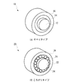
近年は、燃費向上を目的として、ロッカーアームにローラーを設けたものが多く採用されている。このローラー式は、ボディと称される本体、カムシャフトと摺動する外輪ローラー、外輪ローラーを支持する軸、軸と外輪ローラーとの間にコロと称する小径の実軸あるいは内輪と称する中空のローラーの合計四部品で構成される。前者のコロを用いたタイプを総ころがり式、後者の内輪ローラーを用いたタイプを総すべり式と分類されている。 In recent years, for the purpose of improving fuel efficiency, a rocker arm provided with a roller is often used. This roller type includes a main body called a body, an outer ring roller that slides with a camshaft, a shaft that supports the outer ring roller, a small-diameter real shaft called a roller between the shaft and the outer ring roller, or a hollow roller called an inner ring. It consists of a total of four parts. The former type using a roller is classified as a total rolling type, and the latter type using an inner ring roller is classified as a total sliding type.
図1(A)にすべりタイプのロッカーアームの概略斜視図を示し、図1(B)にころがりタイプのロッカーアームの概略斜視図を示す。但し、ここにはロッカーアームのボディが省略されている。すべりタイプのロッカーアーム10は、ローラー軸12と、ローラー軸12の回転可能に取付けられた内輪ローラー14と、内輪ローラー14の外周上に回転可能に取付けられた外輪ローラー16とを有する。ころがりタイプのロッカーアーム20は、ローラー軸22と、ローラー軸22の外周に回転可能に取付けられた複数のニードルコロ24と、ニードルコロ24の外周上を回転可能に取付けられたローラー26とを有する。
FIG. 1A shows a schematic perspective view of a sliding type rocker arm, and FIG. 1B shows a schematic perspective view of a rolling type rocker arm. However, the body of the rocker arm is omitted here. The sliding-
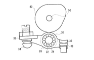
図2は、カムシャフトのカムと吸排気バルブのバルブステムとの間に設置されたころがりタイプのロッカーアームの一例を示す図である。ロッカーアームは、図1(B)に示すようなローラー26を回転可能に保持したボディ30を含み、ボディ30の一方の端部32がピボット部34によって支持され、他方の端部36が吸排気バルブのバルブステムのキャップ38に当接される。ローラー26はカム40に当接され、カム40の回転運動がボディ30に伝達される。こうして、カム40の回転に応じて他方の端部36が吸排気バルブを上下動させる。すべりタイプのロッカーアームもまたこれと同様に用いられる。
FIG. 2 is a view showing an example of a rolling-type rocker arm installed between the cam of the camshaft and the valve stem of the intake / exhaust valve. The rocker arm includes a
総ころがり式は、エンジン運転時にコロが転がる状態で使用されるため、総すべり式と比較してフリクション性能は良好となる。しかし、コロは、軸あるいは外輪と線接触に近い摺動状態となる。特にコロと軸は、コロの外径が小さく軸と凸R同士の接触となるため、ヘルツの接触理論より面圧が高くなる。 Since the total rolling type is used in a state where the roller rolls during engine operation, the friction performance is better than that of the total sliding type. However, the roller is in a sliding state close to line contact with the shaft or outer ring. In particular, the roller and the shaft have a small outer diameter and contact between the shaft and the convex R, so that the surface pressure is higher than the Hertz contact theory.
一方、総すべり式は、カムシャフトのリフト荷重を外輪ローラーの内周と内輪ローラーの外周、内輪ローラーの内周とローラー軸の外周の面で支持する。最も面圧が高くなる内輪ローラーとローラー軸は、コロと比較して内輪ローラーの内径が大きく、ローラー軸に対し凹Rと凸Rの接触となるため、総ころがり式よりも面圧が低い状態で使用される。各摺動面には、クリアランスが存在し、すべりながら相対運動をするため、フリクション性能は悪化する。 On the other hand, the total sliding type supports the lift load of the camshaft on the inner circumference of the outer ring roller and the outer circumference of the inner ring roller, the inner circumference of the inner ring roller, and the outer circumference of the roller shaft. The inner ring roller and roller shaft, which have the highest surface pressure, have a larger inner diameter than the roller and the inner ring roller is in contact with the concave R and convex R against the roller shaft. Used in. Each sliding surface has a clearance and performs relative motion while sliding, so that the friction performance deteriorates.
燃費向上のためには、これら摺動部のフリクションを減ずることが必要である。また、長期にわたって円滑にリフト動作を伝達する機能を確保するためには、これらの摺動部は磨耗しないことや焼付かないことが必要である。このような従来のロッカーアームにおいて、磨耗を抑制したり(特許文献1)、潤滑油を効率的に供給したり(特許文献2、3)する技術が開示されている。また、内輪ローラーの周面に潤滑性皮膜を加工することにより、損傷や焼付を防止する技術が開示されている(特許文献4)。 In order to improve fuel consumption, it is necessary to reduce the friction of these sliding portions. Further, in order to ensure the function of smoothly transmitting the lift operation over a long period of time, it is necessary for these sliding portions not to be worn or seized. In such a conventional rocker arm, techniques for suppressing wear (Patent Document 1) and supplying lubricating oil efficiently (Patent Documents 2 and 3) are disclosed. Further, a technique for preventing damage and seizure by processing a lubricating film on the peripheral surface of the inner ring roller is disclosed (Patent Document 4).
総すべり式ロッカーアームは、外輪ローラーの内周と内輪ローラーの外周、内輪ローラーの内周とローラー軸の外周がそれぞれ摺動面として機能し、この部分にクリアランスを設けてある。従来は、この摺動面の製作は、研磨で形状を作成した後、バレルにて面粗度の調整を行った加工仕上げとなっている。 In the total sliding rocker arm, the inner circumference of the outer ring roller and the outer circumference of the inner ring roller, the inner circumference of the inner ring roller, and the outer circumference of the roller shaft function as sliding surfaces, respectively, and a clearance is provided in this portion. Conventionally, the sliding surface is manufactured by finishing the shape by polishing and then adjusting the surface roughness with a barrel.
運動時、この摺動面への潤滑は、シリンダーヘッド内部の雰囲気中に存在する飛沫状態の潤滑油を利用した飛沫給油を行っているため、元々潤滑油の供給量が少ない。更に、潤滑油の供給入口である側面部分は、ボディで覆われているために潤滑油の供給を遮る形になり、供給量を減少させている。このため、十分な量の潤滑油を確保することができず、境界潤滑状態での摺動となってしまう。境界潤滑状態では、部分的に固体接触をしているため、フリクション低減や、耐摩耗性、耐焼付性を向上させることは困難である。 At the time of movement, the lubrication to the sliding surface is carried out by splashing using splashed lubricating oil existing in the atmosphere inside the cylinder head, so that the supply amount of lubricating oil is originally small. Further, since the side surface portion that is the supply inlet of the lubricating oil is covered with the body, the supply of the lubricating oil is blocked, and the supply amount is reduced. For this reason, a sufficient amount of lubricating oil cannot be ensured, and sliding occurs in the boundary lubrication state. In the boundary lubrication state, since solid contact is partially made, it is difficult to reduce friction, improve wear resistance, and seizure resistance.
本発明は、上記の課題を解決するため、摺動面に存在する潤滑油を有効に利用し、流体潤滑領域で摺動させることができるロッカーアームを提供することを目的とする。 In order to solve the above-described problems, an object of the present invention is to provide a rocker arm that can effectively use lubricating oil present on a sliding surface and can be slid in a fluid lubrication region.
本発明は、4ストローク内燃機関のロッカーアーム式動弁機構において、構成する部品の一つであるロッカーアームが、ボディと、ローラー軸と、ローラー軸に回転可能に支持された内輪ローラーと外輪ローラーの二つのローラーの合計四部品を有して構成される。このような総すべりしながら摺動するロッカーアームにおいて、ローラー軸の外周面と内輪ローラーの内周面、内輪ローラー外周面と外輪ローラーの内周面の間に生じる各部のクリアランスに供給される潤滑油を有効に利用し、流体潤滑状態とすることでフリクション性能と耐焼付性能を向上させたロッカーアームを提供する。 The present invention relates to a rocker arm type valve operating mechanism for a four-stroke internal combustion engine, in which a rocker arm, which is one of the constituent parts, includes a body, a roller shaft, and an inner ring roller and an outer ring roller that are rotatably supported by the roller shaft. A total of four parts of two rollers. In such a rocker arm that slides while sliding, lubrication supplied to the clearance of each part generated between the outer peripheral surface of the roller shaft and the inner peripheral surface of the inner ring roller, and between the outer peripheral surface of the inner ring roller and the inner peripheral surface of the outer ring roller. Provided is a rocker arm that effectively uses oil and is in a fluid lubrication state to improve friction performance and seizure resistance.
ローラー軸と内輪ローラーの摺動面において、ローラー軸の外周面と内輪ローラーの内周面の片面あるいはその両面に、内輪ローラーと外輪ローラーの摺動面において、内輪ローラーの外周面と外輪ローラーの内周面の片面あるいはその両面に、ディンプル形状の油溜まりを設ける。ディンプルの付与は、従来のロッカーアームのローラーのバレル後に行うため、この工程を追加するだけとなる。好ましい態様では、ディンプル形状は、長さ5mm以下、幅1mm以下、深さ1mm以下の楕円または長方形とし、その断面形状は摺動方向に一定であり、その配置は摺動方向に平行または直角であり、その間隔は一定の等ピッチまたは不等ピッチとする。 On the sliding surface of the roller shaft and inner ring roller, on the outer surface of the roller shaft and one or both surfaces of the inner surface of the inner ring roller, on the sliding surface of the inner ring roller and outer ring roller, on the outer surface of the inner ring roller and the outer ring roller A dimple-shaped oil reservoir is provided on one surface or both surfaces of the inner peripheral surface. Since the dimple is applied after the barrel of the roller of the conventional rocker arm, only this step is added. In a preferred embodiment, the dimple shape is an ellipse or a rectangle having a length of 5 mm or less, a width of 1 mm or less, and a depth of 1 mm or less, its cross-sectional shape is constant in the sliding direction, and its arrangement is parallel or perpendicular to the sliding direction. Yes, and the interval is constant pitch or unequal pitch.
この様なディンプルを摺動面に設けることによって、供給された潤滑油を留めておくことが可能となる。そのため、潤滑油の供給が少量であっても有効に利用することができ、従来の境界潤滑から流体潤滑へ移行することができる。 By providing such dimples on the sliding surface, it is possible to keep the supplied lubricating oil. Therefore, even if a small amount of lubricating oil is supplied, it can be used effectively, and the conventional boundary lubrication can be shifted to fluid lubrication.
本発明によれば、ローラー軸の外周面と内輪ローラーの内周面の片方あるいはその両方に、内輪ローラーの外周面と外輪ローラーの内周面の片方あるいはその両方に、複数の溝(ディンプル)を形成することにより、供給された潤滑油を溝内に効率的に留めることができ、フリクション性能と耐焼付性能を向上させることができる。 According to the present invention, a plurality of grooves (dimples) are formed on one or both of the outer peripheral surface of the roller shaft and the inner peripheral surface of the inner ring roller, and on one or both of the outer peripheral surface of the inner ring roller and the inner peripheral surface of the outer ring roller. By forming, the supplied lubricating oil can be efficiently retained in the groove, and the friction performance and anti-seizure performance can be improved.
次に、本発明を実施するための形態について詳細に説明する。なお、図面は、分かり易くするために各部を強調して示してあり、実際のスケールとは異なることに留意すべきである。 Next, the form for implementing this invention is demonstrated in detail. It should be noted that in the drawings, each part is highlighted for easy understanding, and is different from an actual scale.
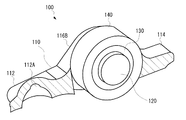
図3は、本発明の実施例に係るロッカーアームの全体を示した斜視図、図4は、図3に示すロッカーアームのボディの一部を除去した図、図5は、各部品の斜視図である。本発明の実施例に係るロッカーアームは、4ストローク内燃機関のロッカーアーム式動弁機構を構成する部品の一つであり、総すべりしながら摺動するロッカーアームのフリクション性能と耐焼付性能を向上させるものである。 3 is a perspective view showing the entire rocker arm according to the embodiment of the present invention, FIG. 4 is a view in which a part of the body of the rocker arm shown in FIG. 3 is removed, and FIG. 5 is a perspective view of each component. It is. The rocker arm according to the embodiment of the present invention is one of the components constituting the rocker arm type valve operating mechanism of a four-stroke internal combustion engine, and improves the friction performance and anti-seizure performance of the rocker arm that slides while sliding. It is something to be made.
本実施例に係るロッカーアーム100は、図3および図4に示すように、ボディ110と、ボディ110内に固定されるローラー軸120と、ローラー軸120の外周上に回転可能に取付けられた内輪ローラー130と、内輪ローラー130の外周上に回転可能に取付けられた外輪ローラー140とを含んで構成される。
As shown in FIGS. 3 and 4, the
ボディ110は、ローラー軸120、内輪ローラー130および外輪ローラー140を支持する金属部材であり、一方の端部112にはピボット部34(図2を参照)を支持するための開口112Aが形成され、他方の端部114が吸排気バルブのバルブステムのキャップ38に当接される。ボディ110の一方の端部112と他方の端部114との間には、離間された一対の側壁116A、116Bが形成され、一対の側壁116A、116Bには、円形状の貫通孔118がそれぞれ形成される。一対の側壁116A、116Bの貫通孔118内には、ローラー軸120が取付けられる。
The
ローラー軸120は、図5(A)に示すように、一様な直径D1を有する円筒状の金属部材であり、上記したように一対の側壁116A、116Bの各貫通孔118内に挿入される。好ましくは、ローラー軸120の直径D1は、貫通孔118の直径とほぼ等しいかそれよりも幾分大きく形成され、ローラー軸120が貫通孔118内にカシメなどにより締結される。
As shown in FIG. 5A, the
内輪ローラー130は、一対の側壁116A、116B間で、ローラー軸120の外周を覆うように取付けられる環状の金属部材である。内輪ローラー130は、図5(B)に示すように、内径D2の内周面132と外径D3の外周面134とを有する。内径D2は、ローラー軸120の直径D1よりも幾分大きく、つまりD2>D1となるように一定のクリアランスS1を持つように形成される。その結果、内輪ローラー130の内周面132は、ローラー軸120の外周面122上を摺動可能である。
The
外輪ローラー140は、一対の側壁116A、116B間で、内輪ローラー130の外周を覆うように取付けられる環状の金属部材である。外輪ローラー140は、図5(C)に示すように、内径D4の内周面142と外周面144を有する。外輪ローラー140の内径D4は、内輪ローラー130の外径D3よりも幾分大きく、つまりD4>D3となるように一定のクリアランスS2を持つように形成される。その結果、外輪ローラー140の内周面142は、内輪ローラー130の外周面134上を摺動可能である。
The
本実施例のロッカーアームの特徴的な点は、ロッカーアームを構成する部品間の摺動面の少なくとも1つに、フリクションを軽減し、耐焼付性能を向上させるためのディンプル、すなわち溝が形成される。ローラー軸120の外周面122、内輪ローラー130の内周面132および外周面134、外輪ローラー140の内周面142のいずれか1つの摺動面に複数のディンプルを形成することにより、潤滑油の供給が少ない状態でも油溜まりに留まった潤滑油を有効に利用し、摺動面を流体潤滑領域で摺動させることでフリクション性能と焼付性能を向上させる。好ましい1つの態様では、加工の容易さから、ローラー軸120と内輪ローラー130間の摺動では、ローラー軸120の外周面122にディンプルを形成し、内輪ローラー130と外輪ローラー140間の摺動では、内輪ローラー130の外周面134にディンプルを形成している。ディンプルは、例えば転写、エッチング、レーザー加工等により形成することができる。
A characteristic feature of the rocker arm of the present embodiment is that dimples, that is, grooves for reducing friction and improving seizure resistance performance are formed on at least one of sliding surfaces between components constituting the rocker arm. The By forming a plurality of dimples on any one sliding surface of the outer
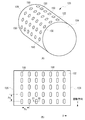
次に、ローラー軸120の外周面122にディンプル150を形成した例を図6に示す。図6(A)は、ローラー軸の外観斜視図、図6(B)は、その平面図である。ローラー軸の端面124、126で規定された長さは、少なくとも内輪ローラー130の軸方向の幅と等しいかそれよりも大きい。
Next, an example in which the
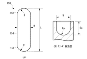
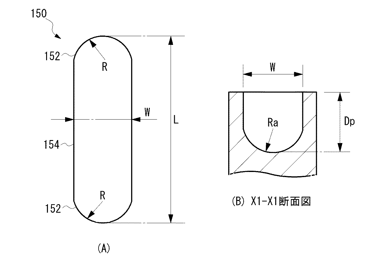
好ましい態様では、複数のディンプル150は、同一の楕円形状から構成される。図7(A)にディンプルの拡大平面図を示す。1つのディンプル150の平面形状は、曲率半径Rの両端部152と、当該両端部152を連結する一定の幅Wの連結部154とを有する、概略楕円状である。ディンプル150の長軸方向の長さLは、例えば5mmかそれ以下であり、幅Wは1mmかそれ以下である。図7(B)にディンプルのX1−X1断面図を示す。好ましくは、ディンプル150は、曲率半径Raの底面から構成される深さDpを有し、例えば深さDpは、1mmかそれ以下である。ディンプル150のY方向深さは、X方向と同じく深さを一定に形成される。ローラーの回転方向によりY方向の深さを変えることもできる。
In a preferred embodiment, the plurality of
このようなディンプル150は、ローラー軸120の外周面122上に、X方向およびY方向に整列するように、かつそれぞれ均等なピッチPx、Pyとなるように形成される。また、ディンプル150は、長軸方向が摺動方向Yと平行になるように配列される。ディンプルのX方向およびY方向のピッチPx、Pyは、ディンプルの大きさ(W、L、Dp)に応じて適宜選択される。
一方、ローラー軸120の外周面122と摺動する内輪ローラー130の内周面132は、平坦に加工された曲面であり、ディンプルの形成を必須とするものではない。摺動面のいずれか一方に、上記のようなディンプル150を均一にかつ二次元的に形成することで、ディンプル150内に潤滑油が保持される。その結果、2つの摺動面間には、ディンプル150によって保持された潤滑油による油膜が均一にかつ二次元的に形成され、それ故、ローラー軸120の外周面122と内輪ローラー130の内周面132間の摺動特性が向上され、フリクションが低減される。さらに、ディンプル150の長手方向が摺動方向に一致するように配列されるので、摺動時に潤滑油がディンプル150内に保持され易くなり、摺動特性がさらに改善される。
On the other hand, the inner
次に、本実施例のディンプルの他の形状の適用例を図8(A)、図8(B)に示す。図8(A)に示すディンプル150Aの平面形状は、4つのコーナー部にR面取りCmが形成された概略矩形状を有する。また、ディンプル150Aの平坦な底面156と側面158との間にはR面取りCmが形成される。また、ディンプル150Bは、図8(B)に示すような面取りが施されていない矩形状であってもよい。このようなディンプル150A、150Bの形状であっても、図7に示すディンプル150と同様の効果を得ることができる。
Next, application examples of other shapes of the dimples of this embodiment are shown in FIGS. 8 (A) and 8 (B). The planar shape of the
なお、ディンプルの平面形状は、上記の楕円、矩形状に限定されるものではない。ディンプルの平面形状は、長軸と短軸とを有する異方形状であることも可能であるし、円、正方形等の点対称または線対称の形状であってもよい。 The planar shape of the dimple is not limited to the above ellipse or rectangle. The planar shape of the dimple may be an anisotropic shape having a major axis and a minor axis, or may be a point-symmetric or line-symmetric shape such as a circle or a square.
次に、本実施例のディンプルの他の配置例について説明する。ディンプルの数および配置は、油膜形成能を十分に発揮できる程度に付与されていれば良い。図9(A)は、図6(B)と比較して、ディンプルの数を減少させた態様を表している。効率的な油膜形成能を考慮して、図9(A)では、ディンプルが千鳥状に配置されている。奇数行のディンプル150AのX方向のピッチPxと、偶数行のディンプル150BのX方向のピッチPxとは等しいが、両ピッチは互いに1/2だけずれている。ディンプル同士のピッチ(Py、Px)は、図6(B)のものよりも大きくなるので、その代わりにディンプルの深さを図6(B)のものよりも大きくし、保油性が減少されないようにしてもよい。図9(B)は、奇数列のディンプル150Cと偶数列のディンプル150DのY方向のピッチPyをそれぞれ半ピッチずらした例を示している。
Next, another arrangement example of the dimples of this embodiment will be described. The number and arrangement of the dimples only have to be given to such an extent that the oil film forming ability can be sufficiently exhibited. FIG. 9A illustrates an aspect in which the number of dimples is reduced as compared with FIG. In consideration of efficient oil film forming ability, in FIG. 9A, the dimples are arranged in a staggered pattern. The pitch Px in the X direction of the
次に、本実施例のディンプルの他の配置例について説明する。上記した例は、ディンプルの長軸方向が摺動方向Yと平行になるように配列されているが、図10(A)、図10(B)に示す例は、ディンプルの長軸方向が摺動方向Yと直交する方向Xと平行になるように配列されている。このようなディンプルの配列であっても、ディンプル内に保持された潤滑油によって摺動面間のフリクション軽減を期待することができる。 Next, another arrangement example of the dimples of this embodiment will be described. In the example described above, the long axis direction of the dimple is arranged so as to be parallel to the sliding direction Y. In the example shown in FIGS. 10A and 10B, the long axis direction of the dimple is slid. They are arranged so as to be parallel to a direction X orthogonal to the moving direction Y. Even with such a dimple arrangement, the friction between the sliding surfaces can be expected to be reduced by the lubricating oil retained in the dimple.
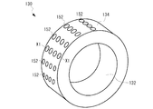
図11に、内輪ローラー130の外周面134にディンプルが形成された斜視図を示す。複数のディンプル152が均一に外周面134に形成される。ここに示す例では、ディンプル152は、1組の直線状に並んだディンプルが、円周方向に複数組形成される例を示しているが、これは一例であり、ディンプル152の数、配列、形状(断面も含む)、大きさ、深さ等は、内輪ローラー130および外輪ローラー140の材質、内輪ローラーの内径D2と外径D3、外輪ローラーの内径D4、摺動面の面積、クリアランスS1等に応じて適宜選択される。
FIG. 11 is a perspective view in which dimples are formed on the outer
次に、本実施例のローラー式ロッカーアームの動作を説明する。 エンジン運転時、シリンダーヘッド内には、カムジャーナルやHLAから排出された潤滑油が飛沫上になって存在している。このような潤滑油が、能動的にロッカーアームの外輪ローラー140や内輪ローラー130を潤滑している。カムシャフトと外輪ローラー140は常時接触しているので、外輪ローラー140は常時回転しており、付着した潤滑油は、クリアランスを介して内部に引き込まれ、摺動面を潤滑する。
Next, the operation of the roller rocker arm of this embodiment will be described. When the engine is in operation, the lubricating oil discharged from the cam journal and HLA is present in the cylinder head as splashes. Such lubricating oil actively lubricates the
図12(A)は、従来の内輪ローラーの外周面の概略断面図、図12(B)は、図11の外周面134のX1−X1線の概略断面図である。図12(A)に示すように、従来の構造では、外周面134にディンプル152が形成されていないため、外周面134には、加工によって形成された面粗度の粗さ成分として谷部分160と山部分170が形成され、内部に引き込まれた潤滑油180は、谷部分160にしか溜まることができない。谷部分160が外周面134に均一に形成されていないので、潤滑油180は外周面134に均一に溜まることができない。このため、山部分170は相手部品と直接接触し、境界潤滑状態となる。更に、飛沫上の潤滑油の供給量が少ないため、十分な厚さの流体膜を形成することができない。それ故、フリクション性能や焼付性能が悪化してしまう。
12A is a schematic cross-sectional view of the outer peripheral surface of a conventional inner ring roller, and FIG. 12B is a schematic cross-sectional view of the outer
一方、本実施例では、図12(B)に示すように、外周面134に均一に複数のディンプル152が形成されるため、クリアランスを介して内部に引き込まれた潤滑油は、図12(C)に示すように、摺動面のディンプル152内に溜まることができる。ディンプル152が谷部分160よりも深ければ、潤滑油の保持がさらに増加する。潤滑油の供給量が少なくても、エンジン運転中は飛沫給油が存在し、常時、外輪ローラーが回転しているため、潤滑油が供給され続けるので油溜まり中の潤滑油が途切れることはない。油溜まりは、面粗度の粗さ成分の谷部分160と山部分170の合計上の深さを有するため、図12(D)に示すように、十分な厚さを持った流体膜190を形成することができる。外輪ローラー140は常時回転しているので、形成された流体膜190は、潤滑油が有する粘性によってくさび膜効果を発生し、流体潤滑状態となる。一方、ローラー軸と内輪ローラー間では、ローラー軸がボディと締結されているので、回転することはない。内輪ローラー130は拘束されていないため自由に回転することができる。内輪ローラー130と外輪ローラー140のクリアランスに形成された流体膜は、流体の性質である粘性抵抗による摩擦を有するため、外輪ローラー140の回転を内輪ローラー130へ伝達することができる。そのためローラー軸と内輪ローラーにおいても同様の効果が発生し、総じて、フリクション性能と耐焼付性能が向上する。
On the other hand, in this embodiment, as shown in FIG. 12 (B), a plurality of
実施例として、ローラー軸120にSUJ2材(JIS G 4805)を焼入処理したものを用い、外周面122に転写によって表1に示した長さL、幅W、深さDpを有する図6に示すディンプル150を形成したものを作製した。内輪ローラー130および外輪ローラー140にSUJ2材(JIS G 4805)を焼入処理したものを用い、内周ローラー130の外周面134にも転写によって表1に示した長さL、幅W、深さDpを有するディンプル150を形成したものを作製した。これらを図示しないボディに組み付け、実施例のすべり式ローラーロッカーアームを作製した。また、本実施例と同材質を用いて、ローラー軸、内輪ローラーにディンプルを形成しない従来技術による比較例のすべり式ローラーロッカーアームを作製した。
As an example, FIG. 6 having the length L, the width W, and the depth Dp shown in Table 1 by transfer onto the outer
前記のように作製した各実施例、比較例について、摩擦抵抗(フリクション)及び耐焼付性(耐スカッフ性)の評価を行った。摩擦抵抗の測定は、動弁機構のみの摩擦損失が測定できる動力計が接続されたモータリングベンチに、本発明の実施例、比較例を組み込んだ実機エンジンをセットしてカムシャフトを回転させ、その駆動トルクを測定した。測定条件は、カムシャフト回転数300rpm、潤滑油の供給温度120℃とし、飛沫潤滑のみにより潤滑油を供給とした。摩擦抵抗は、比較例を基準にしたときに3%程度向上を△、5%以上向上を○で示している。耐焼付性の評価は、摩擦抵抗の測定と同様にモータリングベンチに本発明の実施例、比較例を組み込んだ荷重を負荷できる専用の単体試験機をセットし、摩擦抵抗の評価と同様の条件において、所定時間毎にロッカーアームへの負荷荷重を一定量ずつ増加させていき、スカッフ発生までの荷重を測定した。耐焼付性は、比較例のスカッフ発生荷重との対比で3%程度向上を△、5%以上向上を○で示している。 About each Example and comparative example produced as mentioned above, friction resistance (friction) and seizure resistance (scuff resistance) were evaluated. The friction resistance is measured by setting the actual engine incorporating the embodiment of the present invention and the comparative example on the motoring bench to which the dynamometer capable of measuring the friction loss of only the valve mechanism is connected, rotating the camshaft, The driving torque was measured. The measurement conditions were a camshaft rotation speed of 300 rpm, a lubricating oil supply temperature of 120 ° C., and the lubricating oil was supplied only by splash lubrication. With respect to the frictional resistance, an improvement of about 3% is indicated by Δ, and an improvement of 5% or more is indicated by ○ when the comparative example is used as a reference. For evaluation of seizure resistance, set the dedicated unit tester that can load the motoring bench incorporating the example and comparative example of the present invention in the same way as the measurement of friction resistance, and the same conditions as the evaluation of friction resistance The load applied to the rocker arm was increased by a certain amount every predetermined time, and the load until scuffing was measured. The seizure resistance is indicated by an improvement of about 3% in comparison with the scuffing load of the comparative example, and an improvement of 5% or more by ◯.
これらの実験結果から本実施例のロッカーアームでは、比較例と比べて摩擦抵抗が減少し、耐焼付性が向上したことが確認された。 From these experimental results, it was confirmed that the rocker arm of this example had reduced frictional resistance and improved seizure resistance compared to the comparative example.
以上、本発明の好ましい実施の形態について説明したが、本発明は、特定の実施形態に限定されるものではなく、本発明は、特許請求の範囲に基づき本発明の要旨を逸脱しない範囲で変形、変更が可能である。 The preferred embodiments of the present invention have been described above. However, the present invention is not limited to specific embodiments, and the present invention can be modified based on the claims without departing from the spirit of the present invention. Can be changed.
100:ロッカーアーム
110:ボディ
120:ローラー軸
122:外周面
130:内輪ローラー
132:内周面
134:外周面
140:外輪ローラー
142:内周面
144:外周面
150:ディンプル
100: Rocker arm 110: Body 120: Roller shaft 122: Outer peripheral surface 130: Inner ring roller 132: Inner peripheral surface 134: Outer peripheral surface 140: Outer ring roller 142: Inner peripheral surface 144: Outer peripheral surface 150: Dimple
Claims (5)
ローラー軸であって、当該ローラー軸の外周面の摺動面が複数の溝を含む、前記ローラー軸と、
前記ローラー軸の外周面上に摺動可能に取付けられた内輪ローラーであって、当該内輪ローラーの内周面および外周面が複数の溝を含む、前記内輪ローラーと、
前記内輪ローラーの外周面上に摺動可能に取付けられた外輪ローラーであって、当該外輪ローラーの内周面が複数の溝を含む、前記外輪ローラーとを有し、
それぞれの溝は、長軸と短軸とを有する異方形状を有し、各表面上の複数の溝は摺動する方向および摺動する方向と直交する方向において離間されている、ローラー式ロッカーアーム。 A roller-type rocker arm having a function of transmitting the rotational movement of the cam to the intake and exhaust valves,
A roller shaft , wherein the sliding surface of the outer peripheral surface of the roller shaft includes a plurality of grooves, and the roller shaft;
An inner ring roller slidably mounted on an outer circumferential surface of the roller shaft, the inner circumferential roller and the outer circumferential surface of the inner ring roller including a plurality of grooves,
An outer ring roller slidably mounted on an outer peripheral surface of the inner ring roller, the inner peripheral surface of the outer ring roller including a plurality of grooves, and the outer ring roller ,
Each groove has an anisotropic shape having a major axis and a minor axis, a plurality of grooves on each surface are spaced apart in the direction orthogonal to the direction in which direction and sliding slide, roller type rocker arm.
The roller-type rocker arm according to any one of claims 1 to 4 , wherein the groove has a major axis length of 5 mm or less, a minor axis width of 1 mm or less, and a depth of 1 mm or less.
Applications Claiming Priority (3)
| Application Number | Priority Date | Filing Date | Title |
|---|---|---|---|
| JP2014089859 | 2014-04-24 | ||
| JP2014089859 | 2014-04-24 | ||
| PCT/JP2015/061488 WO2015163198A1 (en) | 2014-04-24 | 2015-04-14 | Roller-type rocker arm |
Publications (2)
| Publication Number | Publication Date |
|---|---|
| JPWO2015163198A1 JPWO2015163198A1 (en) | 2017-04-13 |
| JP6576331B2 true JP6576331B2 (en) | 2019-09-18 |
Family
ID=54332365
Family Applications (1)
| Application Number | Title | Priority Date | Filing Date |
|---|---|---|---|
| JP2016514877A Active JP6576331B2 (en) | 2014-04-24 | 2015-04-14 | Roller type rocker arm |
Country Status (3)
| Country | Link |
|---|---|
| US (1) | US10119428B2 (en) |
| JP (1) | JP6576331B2 (en) |
| WO (1) | WO2015163198A1 (en) |
Families Citing this family (2)
| Publication number | Priority date | Publication date | Assignee | Title |
|---|---|---|---|---|
| US20200300091A1 (en) * | 2017-05-17 | 2020-09-24 | Northwestern University | Surface texture and groove designs for sliding contacts |
| CN107676140B (en) * | 2017-10-17 | 2020-10-16 | 台州立克科技有限公司 | Valve rocker mechanism of motorcycle engine |
Family Cites Families (11)
| Publication number | Priority date | Publication date | Assignee | Title |
|---|---|---|---|---|
| CA1013798A (en) | 1973-01-17 | 1977-07-12 | James W. Cairns | Composite bearings |
| JPS52113445A (en) | 1976-03-19 | 1977-09-22 | Daido Metal Co Ltd | Bearing metal |
| JPS62158218U (en) | 1986-03-31 | 1987-10-07 | ||
| JP2634496B2 (en) * | 1991-02-28 | 1997-07-23 | エヌティエヌ株式会社 | Cam follower with roller for engine |
| JPH08291823A (en) * | 1995-04-20 | 1996-11-05 | Asmo Co Ltd | Oil impregnated metal powder sintered bearing and rotation shaft |
| JP3640140B2 (en) | 1998-07-21 | 2005-04-20 | 日本精工株式会社 | Engine tappet roller support bearing |
| JP4103602B2 (en) | 2003-01-20 | 2008-06-18 | 日産自動車株式会社 | Sliding member, crankshaft, and variable compression ratio engine |
| JP2007023817A (en) | 2005-07-13 | 2007-02-01 | Nissan Diesel Motor Co Ltd | Rocker arm for engine |
| JP2007263023A (en) | 2006-03-29 | 2007-10-11 | Nissan Diesel Motor Co Ltd | Rocker arm for engine |
| JP4992521B2 (en) | 2007-04-04 | 2012-08-08 | 日本精工株式会社 | Rocker arm |
| JP2012241774A (en) | 2011-05-18 | 2012-12-10 | Nisshin Seisakusho:Kk | Rotation body and rocker arm |
-
2015
- 2015-04-14 JP JP2016514877A patent/JP6576331B2/en active Active
- 2015-04-14 WO PCT/JP2015/061488 patent/WO2015163198A1/en not_active Ceased
- 2015-04-14 US US15/306,053 patent/US10119428B2/en active Active
Also Published As
| Publication number | Publication date |
|---|---|
| WO2015163198A1 (en) | 2015-10-29 |
| JPWO2015163198A1 (en) | 2017-04-13 |
| US10119428B2 (en) | 2018-11-06 |
| US20170044936A1 (en) | 2017-02-16 |
Similar Documents
| Publication | Publication Date | Title |
|---|---|---|
| JP6102137B2 (en) | Rolling bearing | |
| JP6298241B2 (en) | Cam structure | |
| EP2546480A1 (en) | Tappet roller bearing | |
| JP6576331B2 (en) | Roller type rocker arm | |
| JP4749399B2 (en) | Piston of internal combustion engine | |
| JP2008095721A (en) | Sliding member | |
| JP2011241894A (en) | Split rolling bearing, and bearing device with the same | |
| JP2012241774A (en) | Rotation body and rocker arm | |
| JP5515475B2 (en) | Bearing device for tappet roller | |
| US8556514B2 (en) | Sliding support structure for shaft member | |
| US20070221155A1 (en) | CAM follower | |
| US7387098B2 (en) | Cam follower | |
| JP4830309B2 (en) | Rolling and sliding parts | |
| JP5577969B2 (en) | Tappet roller | |
| JP5983061B2 (en) | Plain bearing | |
| JP2015206288A (en) | Roller type rocker arm | |
| CN102667074B (en) | Cam follower with improved structure to be able to increase ultimate load | |
| JP6419727B2 (en) | Valve lifter | |
| JP2020148209A (en) | Sliding bearing | |
| JP2014114913A (en) | Rocker arm bearing | |
| JP2006057658A (en) | Bearing for rocker arm of engine | |
| JP2005326023A (en) | Roller support bearing device | |
| US20150233459A1 (en) | Cam follower or eccentric follower with roller supported by plain bearing mounting | |
| JP2008039055A (en) | Roller support bearing device | |
| JP6914291B2 (en) | Internal combustion engine cylinder |
Legal Events
| Date | Code | Title | Description |
|---|---|---|---|
| A621 | Written request for application examination |
Free format text: JAPANESE INTERMEDIATE CODE: A621 Effective date: 20180405 |
|
| A131 | Notification of reasons for refusal |
Free format text: JAPANESE INTERMEDIATE CODE: A131 Effective date: 20190108 |
|
| A521 | Request for written amendment filed |
Free format text: JAPANESE INTERMEDIATE CODE: A523 Effective date: 20190301 |
|
| TRDD | Decision of grant or rejection written | ||
| A01 | Written decision to grant a patent or to grant a registration (utility model) |
Free format text: JAPANESE INTERMEDIATE CODE: A01 Effective date: 20190813 |
|
| A61 | First payment of annual fees (during grant procedure) |
Free format text: JAPANESE INTERMEDIATE CODE: A61 Effective date: 20190820 |
|
| R150 | Certificate of patent or registration of utility model |
Ref document number: 6576331 Country of ref document: JP Free format text: JAPANESE INTERMEDIATE CODE: R150 |
|
| R250 | Receipt of annual fees |
Free format text: JAPANESE INTERMEDIATE CODE: R250 |
|
| R250 | Receipt of annual fees |
Free format text: JAPANESE INTERMEDIATE CODE: R250 |
|
| R250 | Receipt of annual fees |
Free format text: JAPANESE INTERMEDIATE CODE: R250 |
|
| R250 | Receipt of annual fees |
Free format text: JAPANESE INTERMEDIATE CODE: R250 |