JP6576018B2 - Image processing apparatus and imaging apparatus - Google Patents
Image processing apparatus and imaging apparatus Download PDFInfo
- Publication number
- JP6576018B2 JP6576018B2 JP2013269396A JP2013269396A JP6576018B2 JP 6576018 B2 JP6576018 B2 JP 6576018B2 JP 2013269396 A JP2013269396 A JP 2013269396A JP 2013269396 A JP2013269396 A JP 2013269396A JP 6576018 B2 JP6576018 B2 JP 6576018B2
- Authority
- JP
- Japan
- Prior art keywords
- image signal
- reference value
- image processing
- image
- normalization
- Prior art date
- Legal status (The legal status is an assumption and is not a legal conclusion. Google has not performed a legal analysis and makes no representation as to the accuracy of the status listed.)
- Active
Links
Images


Description
本発明は、画像処理装置および撮像装置に関し、特に、撮像された画像に対して画像処理を行うために用いて好適なものである。 The present invention relates to an image processing apparatus and an imaging apparatus, and is particularly suitable for use in performing image processing on a captured image.
従来から、人物等の被写体を撮影して動画像として記録するデジタルカメラ等の撮像装置が存在する。また、デジタルシネマ等の制作現場においては、カット編集と共に、撮影した画像を所望の見た目に補正するカラーグレーディング処理を施すことが一般的である。このカラーグレーディング処理は、撮影後に、編集スタジオ等においてカラーグレーディング装置を用いて行われる。その一方で、撮影現場において、撮影時に大まかな仮カラーグレーディング(オンセットグレーディング)を行っておき、微調整である本カラーグレーディングを撮影後に行うワークフローも用いられている。このように撮影時に撮影現場で仮カラーグレーディングをしておくことで、最終的な仕上がりの印象を撮影時に把握すると共に、撮影後に行う本カラーグレーディングの負荷を減らすことができる。 2. Description of the Related Art Conventionally, there are imaging devices such as digital cameras that photograph a subject such as a person and record it as a moving image. Also, in production sites such as digital cinema, it is common to perform color grading processing that corrects a photographed image to a desired appearance together with cut editing. This color grading process is performed using a color grading apparatus in an editing studio or the like after shooting. On the other hand, a workflow in which rough provisional color grading (onset grading) is performed at the time of shooting at the shooting site and the main color grading, which is a fine adjustment, is performed after shooting is also used. As described above, provisional color grading is performed at the shooting site at the time of shooting, so that an impression of the final finish can be grasped at the time of shooting and the load of the actual color grading performed after shooting can be reduced.
撮影時に仮カラーグレーディングを行う場合、デジタルカメラは、画像を記録すると共に、3G−SDI、HD−SDIケーブル等を通じて外部のカラーグレーディング装置に対して画像を出力する。カラーグレーディング装置は、入力した画像に対してカラーグレーディング処理を施し、カラーグレーディングのパラメータを記録しておく。また、撮影時に仮カラーグレーディングをカメラ内で行う画像処理装置が開示されている(特許文献1を参照)。 When temporary color grading is performed at the time of shooting, the digital camera records an image and outputs the image to an external color grading apparatus through a 3G-SDI, HD-SDI cable, or the like. The color grading apparatus performs color grading processing on the input image, and records color grading parameters. In addition, an image processing apparatus that performs provisional color grading in a camera at the time of photographing is disclosed (see Patent Document 1).
前述の従来技術によれば、撮影時に仮カラーグレーディングのパラメータを撮影画像に付加する。撮影後の本カラーグレーディング工程においては、撮影時に撮影画像に対して付加しておいた仮カラーグレーディングのパラメータに基づく処理を施すことで、撮影時の仮カラーグレーディングの結果を再現する。ユーザは、仮カラーグレーディング後の画像に対して微調整(本カラーグレーディング)を行う。これにより、前述のとおり、撮影後の本カラーグレーディングの作業の負荷を低減させることができる。 According to the above-described prior art, provisional color grading parameters are added to a captured image at the time of shooting. In the final color grading process after shooting, the result of the temporary color grading at the time of shooting is reproduced by performing processing based on the parameters of the temporary color grading added to the shot image at the time of shooting. The user performs fine adjustment (main color grading) on the image after provisional color grading. Thereby, as described above, it is possible to reduce the work load of the main color grading after photographing.
しかしながら、仮カラーグレーディング装置と本カラーグレーディング装置とで処理するレンジが異なる場合、仮カラーグレーディング装置で行った仮カラーグレーディング処理を、本カラーグレーディング処理で再現できないということがあり得る。
そこで、本発明は、画像処理装置で行われた画像処理の内容を、別の画像処理装置で再現できるようにすることを目的とする。
However, if the range processed by the provisional color grading apparatus and this color grading apparatus are different, the provisional color grading process performed by the provisional color grading apparatus may not be reproduced by the present color grading process.
Therefore, an object of the present invention is to enable the content of image processing performed by an image processing device to be reproduced by another image processing device.
本発明の画像処理装置の第1の例は、画像信号を入力する入力手段と、前記画像信号の値のうち、前記画像信号の値を正規化する際の基準となる値である正規化基準値を取得する正規化基準値取得手段と、前記正規化基準値に従って、前記画像信号を正規化する正規化手段と、前記正規化された画像信号に対して画像処理を行う画像処理手段と、前記画像処理を行った際に使用されたパラメータと、前記画像処理を行う前の画像信号における前記正規化基準値とを相互に関連付けて外部装置に出力する出力手段と、を有することを特徴とする。
本発明の画像処理装置の第2の例は、画像信号を入力する入力手段と、外部の画像処理装置で画像信号に対する画像処理を行った際に使用されたパラメータを取得するパラメータ取得手段と、前記画像処理を行う前の画像信号における画像信号の値のうち、画像信号の値を正規化する際の基準となる値である正規化基準値を取得する正規化基準値取得手段と、前記正規化基準値に従って、前記入力手段により入力された画像信号を正規化する正規化手段と、前記正規化された画像信号に対して前記パラメータを用いて前記画像処理を行う画像処理手段と、を有し、前記パラメータと前記正規化基準値とが相互に関連付けられていることを特徴とする。
A first example of an image processing apparatus according to the present invention includes: an input unit that inputs an image signal; and a normalization criterion that is a reference value for normalizing the value of the image signal among the values of the image signal A normalization reference value acquisition means for acquiring a value; a normalization means for normalizing the image signal according to the normalization reference value; an image processing means for performing image processing on the normalized image signal; Output means for correlating the parameters used when the image processing is performed and the normalized reference value in the image signal before the image processing is output to an external device ; To do.
A second example of the image processing apparatus of the present invention includes an input unit that inputs an image signal, a parameter acquisition unit that acquires a parameter used when image processing is performed on the image signal by an external image processing device, Normalization reference value acquisition means for acquiring a normalization reference value that is a reference value for normalizing the value of the image signal among the values of the image signal in the image signal before performing the image processing; A normalizing unit that normalizes the image signal input by the input unit according to a normalization reference value; and an image processing unit that performs the image processing on the normalized image signal using the parameter. The parameter and the normalization reference value are associated with each other.
本発明によれば、画像処理装置で行われた画像処理の内容を、別の画像処理装置で再現することができる。 According to the present invention, the contents of the image processing performed by the image processing apparatus can be reproduced by another image processing apparatus.
以下に、図面を参照しながら、本発明の実施形態を詳細に説明する。
(第1の実施形態)
まず、第1の実施形態を説明する。本実施形態では、カラーグレーディングに相当する画像処理を撮影中に行い、当該カラーグレーディングのパラメータを記録し、当該パラメータを用いてカラーグレーディングに相当する画像処理を撮影後に行う場合を例に挙げて説明する。
Hereinafter, embodiments of the present invention will be described in detail with reference to the drawings.
(First embodiment)
First, the first embodiment will be described. In this embodiment, an example is described in which image processing corresponding to color grading is performed during shooting, the parameters of the color grading are recorded, and image processing corresponding to color grading is performed after shooting using the parameters. To do.
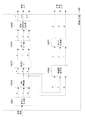
図1は、カラーグレーディング処理を行う機器の関係(カラーグレーディングシステムの構成)の一例を示す図である。
図1において、撮像装置100は、デジタルカメラである。仮カラーグレーディング装置300は、撮像時の画像に対して、色・輝度の補正等の仮カラーグレーディングを施す。モニタ200は、仮グレーディングが施された画像を表示する。本カラーグレーディング装置400は、撮像装置100で撮像された画像に対して本カラーグレーディング処理を行う。モニタ201は、本グレーディング処理が施された画像を表示する。カラーグレーディング処理を施すことにより、画像の見た目(ルック)が変更される。
FIG. 1 is a diagram illustrating an example of the relationship between devices that perform color grading processing (configuration of a color grading system).
In FIG. 1, an
図1に示すカラーグレーディングシステムにおける各機器の動作の概要の一例を説明する。
撮像装置100は、被写体を撮像し、撮像した画像を記録メディアに記録すると共に、撮像中の画像をHD−SDIケーブル等を通じて仮カラーグレーディング装置300に出力する。仮カラーグレーディング装置300は、撮像装置100から入力された撮像中の画像に対して仮カラーグレーディング処理を行い、画像の見た目(ルック)を大まかに調整する。仮カラーグレーディング装置300は、仮カラーグレーディング処理を行った後の画像を、3G−SDIケーブル等を通じてモニタ200に出力する。
An example of an outline of the operation of each device in the color grading system shown in FIG. 1 will be described.
The
本カラーグレーディング装置400は、撮像装置100による撮像が終了した後に、撮像装置100で撮像された画像信号を、記録媒体から読み出す。また、本カラーグレーディング装置400は、仮カラーグレーディング装置300から出力されるカラーグレーディングのパラメータに基づき、記録媒体から読み出した画像データに対して、仮カラーグレーディングと等価な処理を施す。更に、本カラーグレーディング装置400は、仮カラーグレーディングと同等の処理を行った後の画像に対して、本カラーグレーディング処理を行い、画像の詳細なルックの調整を行う。また、本カラーグレーディング装置400は、本カラーグレーディング処理を行った後の画像信号を、3G−SDIケーブル等を通じてモニタ201へ出力する。
The color grading apparatus 400 reads the image signal captured by the
次に、図1に示したカラーグレーディングシステムにおける各機器の詳細な構成の一例について説明する。
図2は、撮像装置100の構成の一例を示す図である。
図2において、レンズ群101は、ズームレンズ、フォーカスレンズ等を含む。シャッター102は、絞り機能を備える。撮像部103は、光学像を電気信号に変換するCCDやCMOS素子等を備える。A/D変換器104は、撮像部103から出力されたアナログ信号をデジタル信号に変換する。画像処理部105は、A/D変換器104から出力される画像信号に対し、ホワイトバランス処理、γ処理、色補正処理等の各種画像処理を行う。メモリ制御部107は、画像メモリ106における記憶動作を制御する。D/A変換器108は、メモリ制御部107から入力したデジタル信号をアナログ信号に変換する。表示部109は、画像の表示を行うLCD等の表示器である。コーデック部110は、画像データを圧縮符号化・復号化する。
Next, an example of a detailed configuration of each device in the color grading system illustrated in FIG. 1 will be described.
FIG. 2 is a diagram illustrating an example of the configuration of the
In FIG. 2, the
記録インタフェース(I/F)111は、記録媒体112との間でデータの授受を行う。記録媒体112は、メモリカードやハードディスク等の外部記録媒体である。外部出力インタフェース(I/F)113は、仮カラーグレーディング装置300等の外部の装置への画像信号の出力を制御する。システム制御部50は、撮像装置100のシステム全体を制御する。
A recording interface (I / F) 111 exchanges data with the
操作部120は、撮像装置100に対してユーザが各種の動作指示を入力するためのものである。不揮発性メモリ121は、電気的にデータの消去・記録が可能なメモリであり、例えばEEPROM等が不揮発性メモリ121として用いられる。
システムタイマ124は、各種制御に用いる時間や、内蔵された時計の時間を計測する。システムメモリ125は、システム制御部50の動作に必要な定数・変数や、不揮発性メモリ121から読み出したプログラム等を展開する。通信部126は、仮カラーグレーディング装置300等の外部の装置と無線で通信を行う。
The operation unit 120 is for the user to input various operation instructions to the
The
次に、被写体を撮像する際の撮像装置100における基本的な処理の流れの一例について説明する。
撮像部103は、レンズ群101及びシャッター102を介して入射した光を光電変換し、アナログの画像信号としてA/D変換器104へ出力する。A/D変換器104は、撮像部103から出力されるアナログの画像信号をデジタルの画像信号に変換して画像処理部105に出力する。
Next, an example of a basic processing flow in the
The
画像処理部105は、A/D変換器104から出力された画像信号、又は、メモリ制御部107から読み出した画像信号に対し、ホワイトバランス等の色変換処理、γ処理等を行う(これらの処理の詳細については後述する)。また、画像処理部105は、A/D変換器104から出力された画像信号を用いて所定の演算処理を行う。システム制御部50は、当該演算処理の結果に基づいて、露光制御、測距制御を行う。これにより、TTL(スルー・ザ・レンズ)方式のAF(オートフォーカス)処理や、AE(自動露出)処理等が行われる。画像処理部105は更に、A/D変換器104から出力された画像信号を用いて光源を推定し、推定した光源に基づきAWB(オートホワイトバランス)処理を行う。
The
画像処理部105から出力された画像信号は、画像データとして、メモリ制御部107を介して画像メモリ106に書き込まれる。画像メモリ106は、A/D変換器104から出力された画像信号や、表示部109に表示するための画像信号を、画像データとして格納する。
D/A変換器108は、画像メモリ106に格納されている表示用の画像データをアナログの信号に変換して表示部109に供給する。表示部109は、LCD等の表示器に、D/A変換器108から出力されたアナログの信号に応じた表示を行う。また、メモリ制御部107は、画像メモリ106に格納されている画像データを、外部出力インタフェース113を介して、外部の仮カラーグレーディング装置300に出力する。
The image signal output from the
The D /
コーデック部110は、画像メモリ106に記録された画像データをMPEG等の規格に基づきそれぞれ圧縮符号化する。システム制御部50は、コーデック部110で符号化された画像データ、又は、非圧縮の画像データを、記録インタフェース111を介して記録媒体112に格納する。
以上、撮像装置100の撮像時の基本動作について説明した。
The codec unit 110 compresses and encodes the image data recorded in the
In the above, the basic operation at the time of imaging of the
以上の基本動作以外に、システム制御部50は、前述した不揮発性メモリ121に記録されたプログラムを実行することで、後述する本実施形態の各処理を実現する。ここでいうプログラムとは、本実施形態にて後述する各種フローチャートおよびシーケンス図の内容を実行するためのプログラムのことである。この際、システム制御部50の動作用の定数・変数や、不揮発性メモリ121から読み出されたプログラム等は、システムメモリ125に展開される。
In addition to the basic operations described above, the
次に、撮像装置100の画像処理部105の処理の詳細の一例を説明する。図3は、画像処理部105の詳細な構成の一例を示す図である。
図3において、画像処理部105は、色信号生成部1051、WB(ホワイトバランス)増幅部1052、色補正処理部1053、ガンマ処理部1054、輝度・色差信号生成部1055、色空間変換部1056、及びガンマ処理部1057を有する。
Next, an example of details of processing of the
In FIG. 3, an
前述したように、図2に示したA/D変換器104から画像処理部105に画像信号が入力される。
画像処理部105に入力された画像信号は、ベイヤーRGBのRAW形式の信号であり、色信号生成部1051に入力される。
As described above, an image signal is input to the
The image signal input to the
色信号生成部1051は、入力された画像信号に対して同時化処理を行い、RGBの色信号R、G、Bを生成する。色信号生成部1051は、生成したRGBの色信号R、G、BをWB増幅部1052へ出力する。
WB増幅部1052は、システム制御部50で算出されるホワイトバランスゲイン値に基づき、RGBの色信号R、G、Bにゲインをかけ、ホワイトバランスを調整する。
The color
Based on the white balance gain value calculated by the
色補正処理部1053は、ホワイトバランスが調整されたRGBの色信号R、G、Bに対して、3×3のマトリクス演算処理や3次元のLUT(Look Up Table)処理を行い、色調を補正する。
ガンマ処理部1054は、色調が補正されたRGBの色信号R、G、Bに対して、Rec.709等の規格に沿ったガンマや、ログ形式のガンマを掛ける等のガンマ補正を行う。
The color
The
輝度・色差信号生成部1055は、ガンマ補正が行われたRGBの色信号R、G、Bから、輝度信号Yと色差信号R−Y、B−Yとを生成する。輝度・色差信号生成部1055は、生成した輝度信号Y・色差信号R−Y、B−Yを、外部出力インタフェース113及び記録インタフェース111へ出力する。
一方、色空間変換部1056は、ホワイトバランスが調整されたRGBの色信号R、G、Bの色空間を、外部モニタ出力用の色空間に変換する。
The luminance / color difference
On the other hand, the color
本実施形態では、外部モニタ出力用の色空間として、sRGB色空間、又は、ACES色空間に変換する場合を例に挙げて説明する。ACES色空間は、映画芸術科学アカデミー(AMPAS)が提案しているACES(Academy Color Encording System)規格の色空間である。 In the present embodiment, a case where the color space for external monitor output is converted to the sRGB color space or the ACES color space will be described as an example. The ACES color space is an ACES (Academy Color Encoding System) standard color space proposed by the Academy of Motion Picture Arts and Sciences (AMPAS).
外部モニタ出力用の色空間がsRGB色空間である場合、色空間変換部1056は、ホワイトバランスが調整されたRGBの色信号R、G、BのRGB値を、sRGB色空間のRGB値に変換する処理を行う。一方、外部モニタ出力用の色空間がACES色空間である場合、色空間変換部1056は、ホワイトバランスが調整されたRGBの色信号R、G、Bに対して、ACES規格におけるIDT(Input Device Transform)処理を行う。このIDT処理により、ACES色空間のRGB値が生成される。尚、IDT処理は、色再現性の補正処理と、色空間の変換処理とを含む処理である。
When the color space for external monitor output is the sRGB color space, the color
ガンマ処理部1057は、色空間変換部1056で色空間が変換されたリニアな画像信号に対して、ガンマ処理(ガンマ補正)を施す。具体的に、外部モニタ出力用の色空間がsRGB色空間である場合、ガンマ処理部1057は、色空間変換部1056で色空間が変換されたリニアな画像信号に対して、撮像装置100独自のログガンマ(本実施形態ではログガンマ1とする)を適用する。ガンマ処理部1057は、ガンマ処理を行った後の画像信号(sRGB信号)を外部出力インタフェース113へ出力する。尚、ログガンマとは、入出力の関係が対数関数の関係で表されるガンマ曲線をいう。
一方、外部モニタ出力用の色空間がACES色空間である場合、ガンマ処理部1057は、色空間変換部1056で色空間が変換されたリニアな画像信号に対して、ACES−Proxy形式のガンマを掛けるガンマ処理を行う。ガンマ処理部1057は、ガンマ処理を行った後の画像信号(RGB信号(ACES信号(ACES−Proxy RGB)))を外部出力インタフェース113へ出力する。尚、ACES−Proxyとは、現在規格化が進行中のACES信号の伝送規格である。
以上、画像処理部105の詳細について説明した。
The
On the other hand, when the color space for external monitor output is the ACES color space, the
The details of the
図2の説明に戻り、記録インタフェース111は、記録媒体112との間でやりとりされる信号を制御して、入力された画像信号を画像データとして記録媒体112に出力する。本実施形態で記録媒体112に記録される画像データは、前述のベイヤーRGBのRAW形式の信号、又は、輝度信号Y・色差信号R−Y、B−Yである。
また、外部出力インタフェース113は、画像処理部105から出力されたガンマ処理後の画像信号(ACES信号等)を、3G−SDI信号として伝送できる形に変形し、ガンマ処理後の画像信号を仮カラーグレーディング装置300に出力する。
以上、撮像装置100の構成と、撮像時の画像信号の流れについて説明した。
Returning to the description of FIG. 2, the recording interface 111 controls a signal exchanged with the
Also, the
The configuration of the
次に、仮カラーグレーディング装置300の構成及び動作の一例について説明する。
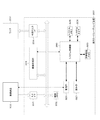
図4は、仮カラーグレーディング装置300の概略構成の一例を示す図である。
図4において、入力インタフェース(I/F)301は、撮像装置100から出力された画像信号を受信する。画像メモリ302は、画像信号を記憶する。画像処理部303は、画像信号に対して、色変換や階調変換等の各種画像処理を行う。外部モニタインタフェース(I/F)304は、外部モニタであるモニタ200(外部の表示装置)への出力を制御する。
Next, an example of the configuration and operation of the provisional
FIG. 4 is a diagram illustrating an example of a schematic configuration of the provisional
In FIG. 4, an input interface (I / F) 301 receives an image signal output from the
システム制御部350は、仮カラーグレーディング装置300のシステム全体を制御する。操作部320は、マウスやキーボード、タッチパネル等から構成され、仮カラーグレーディング装置300に対してユーザが各種の動作指示を入力するためのものである。通信部321は、撮像装置100等の外部機器と通信を行う。
The
不揮発性メモリ323は、電気的にデータの消去・記録が可能なメモリである。システムタイマ324は、各種制御に用いる時間や、内蔵された時計の時間を計測する。システムメモリ325は、システム制御部350の動作に必要な定数・変数や、不揮発性メモリ323から読み出したプログラム等を展開する。
The
次に、以上のように構成された仮カラーグレーディング装置300の基本的な動作の一例を説明する。ここでは、前述の撮像装置100の外部出力インタフェース113を介して出力された画像信号を、入力インタフェース301で受信し、受信した画像信号に対して、仮カラーグレーディング処理する場合を例に挙げて説明する。
Next, an example of the basic operation of the provisional
システム制御部350は、入力インタフェース301を介して入力された、撮像装置100からの画像信号を、画像メモリ302に記録する。
システム制御部350は、ユーザによる入力指示と後述の制御とによって、画像処理部303で画像処理(仮カラーグレーディング処理)を行う際に使用するパラメータを決定し、画像処理部303へ当該パラメータを設定する。
The
The
画像処理部303は、設定されたパラメータに従って仮カラーグレーディング処理を含む画像処理を画像信号に対して行い、当該画像処理を行った画像信号を画像メモリ302に記録する。また、システム制御部350は、仮カラーグレーディング処理が行われた後の画像信号を画像メモリ302から読み出し、外部モニタインタフェース304を介して、モニタ200へ出力する。
以上、仮カラーグレーディング装置300において、撮像装置100から出力された画像信号に対して、仮カラーグレーディング処理を行い、仮カラーグレーディング処理を行った後の画像信号を外部のモニタ200へ出力する処理の流れについて説明した。
The
As described above, the provisional
次に、仮カラーグレーディング装置300の画像処理部303の処理の詳細の一例を説明する。図5(a)は、仮カラーグレーディング装置300の画像処理部303の詳細な構成の一例を示す図である。
正規化処理部501には、撮像装置100から、ガンマ処理が行われた後の画像信号(RGB信号)が入力される。この画像信号(RGB信号)は、前述のとおり、ACES−Proxy規格のRGB信号、又は、sRGB色空間でログガンマ1が適用されたRGB信号である。
Next, an example of details of processing of the
The
正規化処理部501は、入力した画像信号の正規化のポイントを決定し、入力した画像信号を正規化する。本実施形態では、10ビット整数型で入力されたCodeValueで、0〜1023の値を有するRGB信号を、0(ゼロ)〜1の間の値に変換することで正規化を行う。このとき、どのCodeValueを、0(ゼロ)及び1に対応付けるかを決定する必要がある(すなわち、正規化レンジを決定する必要がある)。正規化レンジを決定する方法については後述する。
The
0(ゼロ)〜1の間の値に正規化されたRGB信号R'、G'、B'は、カラーグレーディング処理部502へ入力される。
カラーグレーディング処理部502は、ユーザによる入力指示に応じたカラーグレーディング処理を行う。本実施形態では、カラーグレーディング処理として、ASC(The American Society Of Cinematographers)が定義しているCDL(Color Decision List)で記載可能なカラーグレーディング処理を行うものとする。
CDLに基づくカラーグレーディング処理は、カラーグレーディング処理部502への入力をIn、カラーグレーディング処理部502からの出力をOutで示すと、以下の(1)式で表現することが可能である。
Out=(slope×In+offset)power ・・・(1)
The RGB signals R ′, G ′, and B ′ normalized to a value between 0 (zero) and 1 are input to the color
The color
The color grading process based on CDL can be expressed by the following equation (1), where In is an input to the color
Out = (slope × In + offset) power (1)
ここで、slope、offset、powerが、画像処理部303でカラーグレーディング処理を行う際に使用されるパラメータとなる。尚、以下の説明では、カラーグレーディング処理を行う際に使用されるパラメータを必要に応じて、カラーグレーディング処理のパラメータと称する。
仮カラーグレーディング装置300のシステム制御部350は、カラーグレーディング処理のパラメータ(slope、offset、power)を設定するために操作部320に対してユーザによって行われた操作の内容を受信する。そして、システム制御部350は、当該カラーグレーディング処理のパラメータをカラーグレーディング処理部502に設定する。
Here, slope, offset, and power are parameters used when the
The
カラーグレーディング処理部502は、カラーグレーディング処理が行われた後のRGBの画像信号R''、G''、B''を、表示用処理部503へ出力する。表示用処理部503は、処理対象のRGBの画像信号R''、G''、B''に対して、表示用のガンマ処理等を施す。また、入力されたRGBの画像信号のフォーマットが、ACES‐Proxy規格である場合、カラーグレーディング処理部502は、以下の処理を行う。すなわち、カラーグレーディング処理部502は、ACES規格で定義されているRRT(Reference Rendering Transform)処理・ODT(Output Device Transform)処理を行う。RRT処理によって、表示用に画像の見た目(ルック)の補正が行われ、ODT処理によって、出力先のモニタ200の規格特性に合わせた、ガンマ処理及び色空間の変換が行われる。
The color
本実施形態では、仮カラーグレーディング装置300に接続されたモニタ200がRec.709規格のモニタである場合を例に挙げて説明する。この場合、表示用処理部503は、Rec.709規格の色空間に収まるように、入力信号(RGBの画像信号R''、G''、B'')の色空間を変換する。そして、表示用処理部503は、色空間を変換した入力信号(RGBの画像信号R''、G''、B'')に対して、Rec.709規格に基づくガンマ処理を施す。表示用処理部503は、ガンマ処理を行った後の画像信号(709_RGB信号)を、外部モニタインタフェース304を介してモニタ200へ出力する。
以上、仮カラーグレーディング装置300の構成と、撮像時の画像信号の流れについて説明した。
In the present embodiment, the
The configuration of the provisional
以上のような、撮像装置100、仮カラーグレーディング装置300、及びモニタ200の組み合わせによって、ユーザは、撮像時に、モニタ200に表示された画像を目的の見た目(ルック)に近づけるような仮カラーグレーディングを行うことが可能である。
The combination of the
次に、撮像装置100と仮カラーグレーディング装置300とが通信を行い、カラーグレーディング処理のパラメータ(CDLパラメータ)をやりとりする処理の一例について説明する。
図6は、撮像装置100と仮カラーグレーディング装置300の動作の一例を説明するフローチャートである。
図6のステップS601において、撮像装置100は、通信部126を介して、仮カラーグレーディング装置300との接続を確立する。一方、ステップS611において、仮カラーグレーディング装置300は、通信部321を介して、撮像装置100との接続を確立する。
Next, an example of processing in which the
FIG. 6 is a flowchart for explaining an example of operations of the
In step S <b> 601 of FIG. 6, the
次に、ステップS602において、撮像装置100は、モニタ出力用のフォーマットを設定する。前述のように本実施形態では、モニタ出力用のフォーマットとして、以下のフォーマットA及びフォーマットBの2種類を切り替え可能であるとする。
フォーマットA(色空間:ACES ガンマ:ACES−Proxy)
フォーマットB(色空間:sRGB ガンマ:ログガンマ1)
Next, in step S602, the
Format A (Color space: ACES Gamma: ACES-Proxy)
Format B (color space: sRGB gamma: log gamma 1)
撮像装置100は、操作部120に対するユーザによる入力指示に基づいて、これらのモニタ出力用のフォーマットを切り替えることができる。また、撮像装置100は、仮カラーグレーディング装置300に接続されたモニタ200と通信を行い、モニタ200の設定に応じて、これらのモニタ出力用のフォーマットを切り替えてもよい。撮像装置100は、これらのフォーマットに基づいて決定した色空間及びガンマ特性に応じて、色空間変換部1056及びガンマ処理部1057に、パラメータを設定する。
The
ステップS603において、撮像装置100は、ステップS602で設定したフォーマット情報(ガンマ及び色空間の情報)を、通信部126を介して、仮カラーグレーディング装置300へ送信する。
仮カラーグレーディング装置300の処理に移り、ステップS612において、仮カラーグレーディング装置300は、撮像装置100から送信されたフォーマット情報を取得する。本実施形態では、このようにしてフォーマット情報取得手段の一例が実現される。
In step S603, the
The process proceeds to the provisional
ステップS613において、仮カラーグレーディング装置300は、RGB信号のR、G、Bの値を、0(ゼロ)〜1の間の値に正規化する際の基準となるCodeValue(正規化ポイント)を決定する。
正規化する際の基準となるCodeValueは、フォーマット情報によって決定される。フォーマットが、フォーマットAの場合には、0(ゼロ)の基準をCodeValeで64、1の基準をCodeValueで940とする。一方、フォーマットがフォーマットBの場合には、0の基準をCodeValeで128、1の基準をCodeValueで1019とする。本実施形態では、このようにして正規化基準取得手段の一例が実現される。
In step S613, the provisional
The CodeValue serving as a reference for normalization is determined by the format information. When the format is format A, the reference of 0 (zero) is 64 for CodeValue, and the reference of 1 is 940 for CodeValue. On the other hand, when the format is format B, the standard of 0 is 128 with CodeValue and the standard of 1 is 1019 with CodeValue. In this embodiment, an example of the normalization reference acquisition unit is realized in this way.
ステップS614において、仮カラーグレーディング装置300は、ステップS613で決定した、正規化する際の基準となるCodeValueを、デバイスに非依存の数値に変換する。本実施形態では、デバイスに非依存の数値として、ACES値を用いる。この場合、ACES値に変換できるのは、モニタ出力用のフォーマットがフォーマットA(ACES)の場合のみである。
具体的には、正規化する際の基準となるCodeValueの値[64、940]をACES値に変換すると、[0.0012、224]となる。
In step S614, the provisional
Specifically, when the CodeValue values [64, 940] serving as a reference for normalization are converted into ACES values, [0.0012, 224] is obtained.
ステップS615において、仮カラーグレーディング装置300は、ステップS613で決定した、正規化する際の基準となるCodeValueで、画像信号(RGB信号)を正規化する。そして、仮カラーグレーディング装置300は、正規化した画像信号(RGB信号)に対してCDLに基づくカラーグレーディング処理を(1)式により行う。本実施形態では、このようにして正規化手段と画像処理手段の一例が実現される。
In step S615, the provisional
図7は、正規化とCDLによるカラーグレーディングとの関係の一例を説明する図である。図7は、正規化したRGB信号の値を(1)式(CDLのPowerの式)で変換した場合の入出力特性を示す。
図7(a)は、モニタ出力用のフォーマットがフォーマットAの場合の入出力特性を示す。図7(a)では、[64、940]で正規化した信号に対してPower関数をかけた結果を示す。図7(b)は入力画像のフォーマットがフォーマットBの場合の入出力特性を示す。図7(b)では、[128、1019]で正規化した信号に対してPower関数をかけた結果を示す。図7(a)及び図7(b)において、破線で示す部分が、正規化した信号をPower乗じた値となる((1)式を参照)。
FIG. 7 is a diagram for explaining an example of the relationship between normalization and color grading by CDL. FIG. 7 shows the input / output characteristics when the normalized RGB signal values are converted by Equation (1) (CDL Power Equation).
FIG. 7A shows input / output characteristics when the monitor output format is format A. FIG. FIG. 7A shows the result of applying the Power function to the signal normalized by [64, 940]. FIG. 7B shows input / output characteristics when the format of the input image is format B. FIG. 7B shows the result of applying the Power function to the signal normalized in [128, 1019]. In FIGS. 7A and 7B, a portion indicated by a broken line is a value obtained by multiplying the normalized signal by Power (see equation (1)).
その他のCDLパラメータであるGainとSlopeに関しても、詳細な説明は省略するが、Powerと同様に正規化後のRGBデータに対して処理を行う。
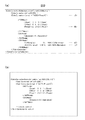
仮カラーグレーディング装置300は、CDLに基づくカラーグレーディング処理を行った後に、CDLファイルを生成する。図8(a)は、CDLファイル800の一例を示す図である。本実施形態では、CDLはタグを用いて記述される。図8(a)に示す(A)は、フォーマット情報を示す。また、(B)は、RGB信号毎のSlope、Offset、Powerのパラメータの値を示す。
Although the detailed description of Gain and Slope as other CDL parameters is omitted, the normalized RGB data is processed in the same manner as Power.
The provisional
図6の説明に戻り、ステップS616において、仮カラーグレーディング装置300は、作成したCDLファイル800に正規化情報を記録・出力する。図8(a)に示す(C)及び(D)は、正規化情報の記録例である。ここで、(C)は、RGB信号の値を正規化する際の基準となるCodeValue(正規化ポイント)である。また、(D)は、正規化する際の基準となるCodeValueを、デバイスに非依存の数値に変換した値(本実施形態ではACES値)である。ただし、フォーマットBのように、正規化する際の基準となるCodeValueを、デバイスに非依存の数値に変換できないフォーマットの場合には、RGB信号の値を正規化する際の基準となるCodeValue(正規化ポイント)のみが記録される。
本実施形態では、このようなCDLファイルを生成することにより、正規化基準の一例である正規化情報と、仮グレーディング処理のパラメータ(CDLパラメータ)とが同一のファイルに記録され、相互に関連付けられる。
Returning to the description of FIG. 6, in step S <b> 616, the provisional
In the present embodiment, by generating such a CDL file, normalization information, which is an example of a normalization standard, and temporary grading processing parameters (CDL parameters) are recorded in the same file and associated with each other. .
図6の説明に戻り、ステップS617において、仮カラーグレーディング装置300は、生成したCDLファイル800を撮像装置100へ送信する。本実施形態では、このようにして出力手段の一例が実現される。
ステップS604において、撮像装置100は、CDLファイル800を受信する。本実施形態では、このようにしてパラメータ取得手段と正規化基準取得手段の一例が実現される。
Returning to the description of FIG. 6, in step S <b> 617, the provisional
In step S604, the
ステップS605において、撮像装置100は、撮像(記録)を行う。
ステップS606において、撮像装置100は、撮像した画像ファイルのファイルヘッダに、ステップS604で取得したCDLファイル800を記録する。図9は、画像ファイルの一例を概念的に示す図である。
In step S605, the
In step S606, the
図9は、撮像装置100で記録するクリップのファイル構成を示す。画像ファイル900は、画像クリップファイル全体を示す、画像ファイル900の内部には、ファイルヘッダ901と、画像フレームデータ910、911とが含まれる。カラーグレーディングパラメータ902は、カラーグレーディング用のCDLパラメータであり、ステップ604で受信したCDLファイル800に記述されたデータである。カラーグレーディングパラメータ902は、ファイルヘッダ901の一部にメタデータとして記録される。本実施形態では、このようにして記録手段の一例が実現される。
以上、撮像装置100及び仮カラーグレーディング装置300における撮像時のカラーグレーディング動作について説明した。
FIG. 9 shows a file structure of a clip recorded by the
The color grading operation at the time of imaging in the
次に、以上のようにして撮像装置100で記録した画像に対して、本カラーグレーディング装置400で、本カラーグレーディング処理する場合の動作の一例について説明する。
本カラーグレーディング装置400の概略構成は、図4に示した仮カラーグレーディング装置300の概略構成と同一であるため、ここでは、その詳細な説明を省略する。本カラーグレーディング装置400は、仮カラーグレーディング装置300と、画像処理部303の構成及び処理内容が異なる。
Next, an example of the operation when the color grading apparatus 400 performs the main color grading process on the image recorded by the
Since the schematic configuration of the present color grading apparatus 400 is the same as the schematic configuration of the provisional
図5(b)は、本カラーグレーディング装置400の画像処理部303の詳細な構成の一例を示す図である。
図5(b)において、色空間変換処理部510は、入力した画像信号(RGB信号)の色空間を変換する。ガンマ処理部511は、色空間が変換された画像信号に対してガンマ処理を施す。正規化・CDL処理部512は、ガンマ処理が施された画像信号に対して、正規化処理と、カラーグレーディング処理とを行う。表示用処理部513は、正規化処理と、カラーグレーディング処理とが行われたRGB信号に対して、表示機器用のガンマ補正や色空間変換等を行う。
FIG. 5B is a diagram illustrating an example of a detailed configuration of the
In FIG. 5B, the color space
色空間変換処理部510は、後述する入力フォーマットの条件に応じて、入力したRGB信号の色空間を変換する。ガンマ処理部511も、後述する入力フォーマットの条件に応じて色空間が変換された画像信号に対してガンマの形状変換を行う。正規化・CDL処理部512は、ガンマ処理が施された画像信号に対して、仮カラーグレーディング装置300で行われた正規化に対応した正規化処理と、CDL処理と、本カラーグレーディング処理と、を行う。表示用処理部513は、モニタ201等の出力機器に応じて、正規化処理、CDL処理、及び本カラーグレーディング処理が行われた画像信号に対して、ガンマ処理と色空間の変換とを行う。
The color space
ここで、本カラーグレーディング装置400で読み出した画像信号の色空間がフォーマットB(色空間:sRGB、ガンマ:ログガンマ1)である場合を例に挙げて、画像処理部303における処理の一例を説明する。
仮カラーグレーディング装置300において、ACES−Proxyで仮カラーグレーディングを行った場合には、本カラーグレーディング装置400の画像処理部303でも画像信号の値をACES値に変換して処理する。
Here, an example of processing in the
In the provisional
色空間変換処理部510は、入力した画像信号の色空間をsRGBからACESに変換する。ここでは、色空間変換処理部510は、ログガンマ1をデガンマした上で、マトリクス処理をかけて、入力した画像信号の色空間をsRGBからACESに変換して、リニアなACES信号R、G、Bをガンマ処理部511に出力する。
ガンマ処理部511は、本カラーグレーディング装置400でカラーグレーディングするために、ACES信号R、G、Bをログガンマに変換する。ここでは、ガンマ処理部511は、ACES信号R、G、Bに対して、ACES−Log規格のログガンマをかける。ACES−Log規格とは、現在規格化策定中のACES信号向けのログガンマである。
The color space
The gamma processing unit 511 converts the ACES signals R, G, and B into log gammas for color grading by the color grading apparatus 400. Here, the gamma processing unit 511 applies the ACES-Log standard log gamma to the ACES signals R, G, and B. The ACES-Log standard is a log gamma for an ACES signal currently being standardized.
正規化・CDL処理部512は、ACES−Log規格のログガンマがかけられたACES信号log_R、log_G、log_Bを、仮カラーグレーディング装置300の正規化値と同じ値で正規化する(この点の詳細については後述する)。その後、正規化・CDL処理部512は、仮カラーグレーディング装置300で行ったCDL処理を行う。さらに、正規化・CDL処理部512は、当該CDL処理以外の本カラーグレーディング処理を行う。表示用処理部513は、正規化と本カラーグレーディング処理が行われたACES信号log_R'、log_G'、log_B'に対し、ACES−Logをリニアに補正する処理、ACES規格のRRT処理、ODT処理(例えばsRGB用のODT)を施す。
The normalization /
一方、仮カラーグレーディング装置300において、フォーマットBでカラーグレーディング処理が行われた場合、色空間変換処理部510、ガンマ処理部511、表示用処理部513では特に処理を行わない。正規化・CDL処理部512は、入力した画像信号に対して、正規化と、仮カラーグレーディング処理で行ったCDL処理と、当該CDL処理以外の本カラーグレーディング処理を行う。
On the other hand, when the color grading process is performed in the format B in the temporary
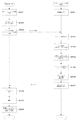
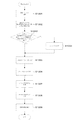
次に、図10のフローチャートを参照しながら、画像ファイルを読み出して本カラーグレーディング処理を行う際の、本カラーグレーディング装置400のシステム制御部350の動作の一例を説明する。
まず、ステップS1001において、システム制御部350は、操作部320に対するユーザによる操作を受け付け、カラーグレーディングする画像ファイル900を選択する。
ステップS1002において、システム制御部350は、画像ファイル900のファイルヘッダ901から、CDL及びCDL処理時のフォーマット情報、正規化情報(カラーグレーディングパラメータ902)を抽出する。本実施形態では、このようにして、正規化基準取得手段の一例が実現される。
Next, an example of the operation of the
First, in step S1001, the
In step S1002, the
ステップS1003において、システム制御部350は、CDLに記載された情報に基づき、仮カラーグレーディング処理の時に入力された画像信号のフォーマットと、現在開いた画像ファイルのフォーマットとが同一であるか否かを判定する。
この判定の結果、フォーマットが同一である場合は、ステップS1005に進み、フォーマットが同一でない場合は、ステップS1004に進む。
In step S1003, based on the information described in the CDL, the
As a result of the determination, if the formats are the same, the process proceeds to step S1005, and if the formats are not the same, the process proceeds to step S1004.
ステップS1004において、システム制御部350は、入力した画像信号の色空間を、仮カラーグレーディング処理を行った画像信号と同一の色空間にするためのパラメータを決定する。そして、システム制御部350は、画像処理部303(色空間変換処理部510、ガンマ処理部511、表示用処理部513)に、決定したパラメータを設定する。
In step S1004, the
例えば、本カラーグレーディング装置400で読み出した画像信号がフォーマットB(色空間:sRGB、ガンマ:ログガンマ1)であるとする。一方、仮カラーグレーディング装置300で得られた画像信号がフォーマットA(色空間:ACES ガンマ:ACES−Proxy)であるとする。この場合、システム制御部350は、入力した画像信号の色空間をACESに変換するパラメータを色空間変換処理部510に設定する。また、システム制御部350は、ガンマ処理部511に、ACES−Log規格のガンマを設定する。ACES−Log規格のガンマの特性を図11(a)に示す。
For example, it is assumed that the image signal read by the color grading apparatus 400 is format B (color space: sRGB, gamma: log gamma 1). On the other hand, it is assumed that the image signal obtained by the provisional
ステップS1005において、システム制御部350は、正規化・CDL処理部512に、正規化のパラメータを設定する。正規化のパラメータは、ステップS1002で取得した正規化情報(カラーグレーディングパラメータ902)に含まれる、仮カラーグレーディング処理時に正規化に用いた値である。
In step S <b> 1005, the
具体的にシステム制御部350は、デバイス非依存であるACES値に基づいた正規化のパラメータを設定する。
ACES−Log規格では、ACES値で65535まで表現できる。
これに対して、仮カラーグレーディング装置300での正規化を、224のACES値で行っていた場合、ACES−Log規格でも、ACES値で224を示すCodeValueで正規化する。正規化の様子を図11(b)に示す。
Specifically, the
In the ACES-Log standard, up to 65535 can be expressed as an ACES value.
On the other hand, when normalization with the provisional
図11(b)は、本カラーグレーディング装置400のガンマ処理部511でACES−Log形式にガンマ変換された画像信号を正規化する様子を示す図である。図11(b)では、入力した画像信号において、0.0012のACES値が0、224のACES値が1になるように正規化している。このようにすることで、仮カラーグレーディング装置300と、本カラーグレーディング装置400との間で、扱えるレンジに差があったとしても、仮カラーグレーディング処理におけるCDL処理を再現することが可能となる。
FIG. 11B is a diagram illustrating a state in which the image signal that has been gamma-converted into the ACES-Log format by the gamma processing unit 511 of the color grading apparatus 400 is normalized. In FIG. 11B, the input image signal is normalized so that the ACES value of 0.0012 is 0 and the ACES value of 224 is 1. In this way, even if there is a difference in the range that can be handled between the provisional
図10の説明に戻り、ステップS1006において、システム制御部350は、仮カラーグレーディング装置300でのカラーグレーディング処理の内容であるCDLパラメータを抽出し(図8(a)を参照)、正規化・CDL処理部512に設定する。前述の様に、224のACES値を1として正規化した後に、Powerの計算を行う。この様子を示したものが、図11(b)である。本実施形態では、このような処理により、パラメータ取得手段の一例が実現される。
Returning to the description of FIG. 10, in step S1006, the
ステップS1007において、システム制御部350は、本カラーグレーディング装置400に接続されたモニタ201の特性情報を取得する。モニタ201と通信してモニタ201の特性情報を取得してもよいし、操作部320に対するユーザの操作を受け付けてモニタ201の特性情報を取得してもよい。
ステップS1008において、システム制御部350は、ステップS1007で取得したモニタ201の特性情報に応じて、表示用処理部513の処理の内容を決定する。例えば、モニタ201が、Rec.709規格用のモニタである場合、表示用処理部513は、Rec.709に適したODT処理を行って出力する。
ステップS1009において、システム制御部350は、読み込んだ画像ファイルに対する処理の開始の指示を、図5(b)の画像処理部303に対して行う。本実施形態では、このような指示に基づいて画像処理部303が処理を行うことにより、正規化手段と画像処理手段の一例が実現される。
In step S <b> 1007, the
In step S1008, the
In step S1009, the
以上のように本実施形態では、仮カラーグレーディング装置300は、フォーマット情報に従って、入力した画像信号の正規化のポイント(正規化する際の基準となるCodeValue)を決定し、入力した画像信号を正規化する。そして、仮カラーグレーディング装置300は、この正規化ポイントをデバイスに非依存の数値に変換した値(正規化情報)を、カラーグレーディングのパラメータに関連付けて記録する。このようにすることで、仮カラーグレーディング処理と、本カラーグレーディング処理との間で扱うダイナミックレンジが異なる場合であっても、等価な処理を行うことができる。よって、撮像時の仮カラーグレーディング処理の結果を、撮像後の本カラーグレーディング処理でより正しく再現することが可能となる。
As described above, in the present embodiment, the provisional
本実施形態では、デバイスに非依存の色空間がACES色空間である場合を例に挙げて説明した。しかしながら、デバイスに非依存の色空間は、ACES色空間に限定するものではない。例えば、独自の色空間を規定し、それを利用することも可能である。
また、本実施形態では、カラーグレーディングのパラメータを記録するCDLファイルの内部に正規化情報を記録する形式を例に挙げて説明した。しかしながら、カラーグレーディングのパラメータと正規化情報とを相互に関連付けて記録する方法であれば、どのような方法をとってもかまわない。例えば、カラーグレーディングのパラメータと正規化パラメータとを個別のファイルで記録しておき、カラーグレーディングのパラメータのファイルに正規化情報のファイルへのリンクを記載しておく方法をとることも可能である。
In this embodiment, the case where the device-independent color space is the ACES color space has been described as an example. However, the device-independent color space is not limited to the ACES color space. For example, it is possible to define a unique color space and use it.
Further, in the present embodiment, the description has been given by taking as an example a format in which normalization information is recorded inside a CDL file in which color grading parameters are recorded. However, any method may be used as long as the color grading parameters and the normalization information are recorded in association with each other. For example, color grading parameters and normalization parameters may be recorded in separate files, and a link to the normalization information file may be described in the color grading parameter file.
また、本実施形態では、仮カラーグレーディング処理のパラメータのファイルを撮像装置100側に転送し、撮像画像のファイルヘッダ901に記録する例について説明した。しかしながら、必ずしも撮像画像に仮カラーグレーディング処理のパラメータを記録する必要はない。例えば、撮像画像のタイムコードに関連付けて仮カラーグレーディング処理のパラメータのファイルを管理する方法等、仮カラーグレーディング処理のパラメータと撮像画像とが相互に関連付けられるのであればどのような構成をとっても構わない。
Further, in the present embodiment, an example in which a parameter file for temporary color grading processing is transferred to the
また、本実施形態では、撮像装置100から、フォーマット情報として、カメラ出力の最大値情報(ACES値で16等)を仮カラーグレーディング装置300に渡す構成としたが、撮像装置100が渡さない構成をとることも可能である。
例えば、以下のようにしてもよい。まず、仮カラーグレーディング装置300は、撮像装置100の機種名や、ガンマ特性に応じたフォーマット情報を予め不揮発性メモリ323に登録しておく。そして、仮カラーグレーディング装置300は、自身に接続された撮像装置100の機種名やガンマ特性に応じて不揮発性メモリ323からフォーマット情報を取得する。
In the present embodiment, the configuration is such that the maximum value information of the camera output (ACES value 16 or the like) is passed as format information from the
For example, the following may be used. First, the provisional
また、本実施形態では、仮グレーディング処理と本グレーディング処理とを行う場合を例に挙げて説明した。しかしながら、処理できる画像信号のダイナミックレンジが異なる装置において、画像信号を補正する処理として同一の画像処理を行う場合であれば、仮グレーディング処理と本グレーディング処理とを行う場合に限定されない。例えば、ガンマ変換を行う場合や、色域の変換を行う場合でも、本実施形態の手法を適用できる。
また、本実施形態では、モニタ出力用のフォーマットが、色空間とガンマ特性との双方を有する場合を例に挙げて説明した。しかしながら、これらの少なくとも何れか一方がフォーマットに含まれていればよい。基本的にはガンマ特性がフォーマットに含まれている必要がある。ただし、色空間のフォーマットが決まると、ガンマ特性が定まる場合がある。
In the present embodiment, the case where the temporary grading process and the main grading process are performed has been described as an example. However, if the same image processing is performed as processing for correcting an image signal in an apparatus having different dynamic ranges of image signals that can be processed, the provisional grading processing and the main grading processing are not limited. For example, the method of the present embodiment can be applied even when performing gamma conversion or color gamut conversion.
In this embodiment, the case where the monitor output format has both a color space and a gamma characteristic has been described as an example. However, at least one of these may be included in the format. Basically, the gamma characteristic needs to be included in the format. However, when the color space format is determined, the gamma characteristic may be determined.
(第2の実施形態)
次に、第2の実施形態を説明する。第1の実施形態では、入力した画像信号のフォーマットに応じて、仮カラーグレーディング装置300側で、画像信号の正規化のポイント(RGB信号の値を正規化する際の基準となるCodeValue)を決定した。これに対して、本実施形態では、撮像装置100側で、画像信号の正規化のポイントを決定する場合について説明する。このように本実施形態と第1の実施形態とは、画像信号の正規化のポイントを決定する方法の一部が主として異なる。すなわち、本実施形態では、撮像装置100及び仮カラーグレーディング装置300のシステム制御部50、350等の処理の一部が第1の実施形態と異なる。したがって、本実施形態の説明において、第1の実施形態と同一の部分については、図1〜図11に付した符号と同一の符号を付す等して詳細な説明を省略する。
(Second Embodiment)
Next, a second embodiment will be described. In the first embodiment, the provisional
本実施形態でも第1の実施形態と同様に、図1に示すカラーグレーディングシステム(撮像装置100、仮カラーグレーディング装置300、本カラーグレーディング装置400、モニタ200、201から構成されるシステム)について説明する。システムの構成は、第1の実施形態と同様である。
In the present embodiment as well, as in the first embodiment, the color grading system shown in FIG. 1 (a system including the
図12は、撮像装置100と仮カラーグレーディング装置300の動作の一例を説明するフローチャートである。
図12のステップS1201において、撮像装置100は、通信部126を介して、仮カラーグレーディング装置300との接続を確立する。一方、ステップS1211では、仮カラーグレーディング装置300は、通信部321を介して、撮像装置100との接続を確立する。
FIG. 12 is a flowchart for explaining an example of the operations of the
In step S1201 of FIG. 12, the
次に、ステップS1202において、撮像装置100は、モニタ出力用のフォーマットを設定する。本実施形態では、モニタ出力用のフォーマットとして、第1の実施形態と同様に、以下のフォーマットA及びフォーマットBの2種類を切り替え可能であるとする。本実施形態では、このようにしてフォーマット情報取得手段の一例が実現される。
フォーマットA(色空間:ACES ガンマ:ACES−Proxy)
フォーマットB(色空間:sRGB ガンマ:ログガンマ1)
撮像装置100は、これらのフォーマットに基づいて決定した色空間及びガンマに応じて、色空間変換部1056及びガンマ処理部1057に、パラメータを設定する。
Next, in step S1202, the
Format A (Color space: ACES Gamma: ACES-Proxy)
Format B (color space: sRGB gamma: log gamma 1)
The
ステップS1203において、撮像装置100は、仮カラーグレーディング装置300で行うCDLでのカラーグレーディング処理において、RGB信号のR、G、Bの値を正規化する際の基準となるCodeValue(正規化ポイント)を決定する。正規化ポイントは、モニタ出力用のフォーマットと、撮像装置100で撮影可能なダイナミックレンジとによって決定される。
例えば、撮像装置100がACES値で10までのレンジを表現できる能力を備えていたとする。この場合、ACES−ProxyにおいてACES値で10を示すCodeValue(例えば、700)を正規化の最大値とする。
前述のフォーマットAの色空間の場合には、CodeValueで[64、700]を[0、1]に正規化する。一方、フォーマットBの場合には、ACES値に変換できないため、ガンマ特性のCodeValueの最大最小値[128、1019]で正規化する。
In step S <b> 1203, the
For example, it is assumed that the
In the case of the format A color space, [64, 700] is normalized to [0, 1] using CodeValue. On the other hand, since the format B cannot be converted to an ACES value, normalization is performed with the maximum and minimum values [128, 1019] of the CodeValue of the gamma characteristic.
ステップS1204において、撮像装置100は、フォーマットAの場合のみ、ステップS1203で決めた正規化ポイントをデバイスに非依存の数値に変換する。本実施形態でも第1の実施形態と同様に、デバイスに非依存の数値としてACES値を用いる。例えば、正規化ポイントをACES値で[0.0012、10]という値に変換する。フォーマットがフォーマットBの場合、撮像装置100は、正規化ポイントをACES値に変換しない。本実施形態では、このようにして正規化基準取得手段の一例が実現される。
In step S1204, the
ステップS1205において、撮像装置100は、ステップS1202、S1204で設定したフォーマット情報を、通信部126を介して、仮カラーグレーディング装置300へ送信する。このフォーマット情報には、ガンマ及び色空間情報と、デバイスに非依存の数値に変換された正規化ポイントとが含まれる。
In step S1205, the
仮カラーグレーディング装置300の処理に移り、ステップS1212において、仮カラーグレーディング装置300は、撮像装置100から送信されたフォーマット情報を取得する。本実施形態では、このようにしてフォーマット情報取得手段の一例が実現される。
ステップS1213において、仮カラーグレーディング装置300は、フォーマット情報に含まれる、デバイスに非依存の数値に変換された正規化ポイントに基づき、画像信号(RGB信号)に対して正規化を行う。本実施形態では、このようにして正規化基準取得手段と正規化手段の一例が実現される。
The process proceeds to the provisional
In step S <b> 1213, the provisional
ステップS1214では、撮像装置100は、正規化した画像信号(RGB信号)に対してCDLに基づくカラーグレーディング処理を(1)式により行い、CDLファイルを生成する。ここで生成されるCDLファイルの一例を図8(b)に示す。
ステップS1215では、仮カラーグレーディング装置300は、CDLファイルを撮像装置100へ送信する。本実施形態では、このようにして出力手段の一例が実現される。
撮像装置100側の処理に戻り、ステップS1206では、撮像装置100は、CDLファイルを受信する。
ステップS1207では、撮像装置100は、撮像(記録)を行う。
ステップS1208では、撮像装置100は、CDLファイルの情報と、正規化ポイントと、デバイスに非依存の数値に変換された正規化ポイント(ACES値)を、画像ファイルのファイルヘッダに記録する。ここで記録されるデータは、第1の実施形態で説明した図9と同様である。本実施形態では、このようにして記録手段の一例が実現される。
In step S1214, the
In step S1215, the provisional
Returning to the processing on the
In step S1207, the
In step S1208, the
以上のように本実施形態では、撮像装置100側で、CDL形式によるカラーグレーディングを行う前に、デバイスに非依存の数値に変換された正規化ポイント(本実施形態ではACES値)を決定し、仮カラーグレーディング装置300に渡す構成とした。これにより、仮カラーグレーディング装置300側で、画像信号の値を正規化する際に、撮像装置100のレンジの特性に応じて、正規化ポイントを変更することが可能となる。
As described above, in the present embodiment, before performing color grading in the CDL format on the
尚、前述した実施形態は、何れも本発明を実施するにあたっての具体化の例を示したものに過ぎず、これらによって本発明の技術的範囲が限定的に解釈されてはならないものである。すなわち、本発明はその技術思想、又はその主要な特徴から逸脱することなく、様々な形で実施することができる。 The above-described embodiments are merely examples of implementation in carrying out the present invention, and the technical scope of the present invention should not be construed in a limited manner. That is, the present invention can be implemented in various forms without departing from the technical idea or the main features thereof.
(その他の実施例)
本発明は、以下の処理を実行することによっても実現される。即ち、まず、以上の実施形態の機能を実現するソフトウェア(コンピュータプログラム)を、ネットワーク又は各種記憶媒体を介してシステム或いは装置に供給する。そして、そのシステム或いは装置のコンピュータ(又はCPUやMPU等)が当該コンピュータプログラムを読み出して実行する。
(Other examples)
The present invention is also realized by executing the following processing. That is, first, software (computer program) for realizing the functions of the above embodiments is supplied to a system or apparatus via a network or various storage media. Then, the computer (or CPU, MPU, etc.) of the system or apparatus reads and executes the computer program.
100:撮像装置、200、201:モニタ、300:仮カラーグレーディング装置、400:本カラーグレーディング装置 100: imaging device, 200, 201: monitor, 300: provisional color grading device, 400: main color grading device
Claims (19)
前記画像信号の値のうち、前記画像信号の値を正規化する際の基準となる値である正規化基準値を取得する正規化基準値取得手段と、
前記正規化基準値に従って、前記画像信号を正規化する正規化手段と、
前記正規化された画像信号に対して画像処理を行う画像処理手段と、
前記画像処理を行った際に使用されたパラメータと、前記画像処理を行う前の画像信号における前記正規化基準値とを相互に関連付けて外部装置に出力する出力手段と、
を有することを特徴とする画像処理装置。 An input means for inputting an image signal;
Normalization reference value acquisition means for acquiring a normalization reference value that is a reference value for normalizing the value of the image signal among the values of the image signal;
Normalization means for normalizing the image signal according to the normalization reference value;
Image processing means for performing image processing on the normalized image signal;
An output unit that correlates the parameters used when the image processing is performed and the normalized reference value in the image signal before the image processing is performed to an external device ;
An image processing apparatus comprising:
前記正規化基準値取得手段は、前記フォーマット情報に基づいて、前記正規化基準値を決定することを特徴とする請求項1に記載の画像処理装置。 Format information acquisition means for acquiring format information including at least one of a gamma characteristic and a color space of the image signal;
The image processing apparatus according to claim 1, wherein the normalization reference value acquisition unit determines the normalization reference value based on the format information.
前記出力手段は、前記パラメータと前記正規化基準値とを相互に関連付けて、前記撮像装置に出力し、
前記パラメータと前記正規化基準値は、前記撮像装置で撮像されて記録された画像信号のファイルの内部に含まれる情報であることを特徴とする請求項1〜4の何れか1項に記載の画像処理装置。 The input means inputs an image signal being imaged by an external imaging device,
The output means correlates the parameter and the normalized reference value and outputs the correlation to the imaging device,
The said parameter and the said normalization reference value are the information contained in the inside of the file of the image signal imaged and recorded by the said imaging device, The any one of Claims 1-4 characterized by the above-mentioned. Image processing device.
外部の画像処理装置で画像信号に対する画像処理を行った際に使用されたパラメータを取得するパラメータ取得手段と、
前記画像処理を行う前の画像信号における画像信号の値のうち、画像信号の値を正規化する際の基準となる値である正規化基準値を取得する正規化基準値取得手段と、
前記正規化基準値に従って、前記入力手段により入力された画像信号を正規化する正規化手段と、
前記正規化された画像信号に対して前記パラメータを用いて前記画像処理を行う画像処理手段と、
を有し、
前記パラメータと前記正規化基準値とが相互に関連付けられていることを特徴とする画像処理装置。 An input means for inputting an image signal;
Parameter acquisition means for acquiring parameters used when image processing is performed on the image signal in an external image processing apparatus;
Normalization reference value acquisition means for acquiring a normalization reference value that is a reference value when normalizing the value of the image signal among the values of the image signal in the image signal before performing the image processing ;
Normalization means for normalizing the image signal input by the input means according to the normalization reference value;
Image processing means for performing the image processing on the normalized image signal using the parameter;
Have
The image processing apparatus, wherein the parameter and the normalization reference value are associated with each other.
前記パラメータ取得手段は、前記ファイルの内部に含まれる前記パラメータを読み出し、
前記正規化基準値取得手段は、前記ファイルの内部に含まれる前記正規化基準値を読み出すことを特徴とする請求項7に記載の画像処理装置。 The input means reads the image signal included in the file of the image signal captured by an external imaging device,
The parameter acquisition means reads the parameter included in the file,
The image processing apparatus according to claim 7, wherein the normalization reference value acquisition unit reads the normalization reference value included in the file.
外部の画像処理装置で画像処理を行った際に使用されたパラメータを、前記外部の画像処理装置から取得するパラメータ取得手段と、
前記画像処理を行う前の画像信号における画像信号の値のうち、画像信号の値を正規化する際の基準となる値である正規化基準値を取得する正規化基準値取得手段と、
前記撮像手段で撮像された画像信号と、前記パラメータと、前記正規化基準値とを相互に関連付けて記録する記録手段と、
を有することを特徴とする撮像装置。 Imaging means;
Parameter acquisition means for acquiring parameters used when image processing is performed by an external image processing apparatus from the external image processing apparatus;
Normalization reference value acquisition means for acquiring a normalization reference value that is a reference value when normalizing the value of the image signal among the values of the image signal in the image signal before performing the image processing ;
A recording unit that records the image signal captured by the imaging unit, the parameter, and the normalized reference value in association with each other;
An imaging device comprising:
前記正規化基準値取得手段は、前記フォーマット情報に基づいて、前記正規化基準値を決定することを特徴とする請求項10〜12の何れか1項に記載の撮像装置。 Having format information acquisition means for acquiring format information including at least one of a gamma characteristic of an image signal and a color space;
The imaging apparatus according to claim 10, wherein the normalization reference value acquisition unit determines the normalization reference value based on the format information.
前記画像信号の値のうち、前記画像信号の値を正規化する際の基準となる値である正規化基準値を取得する正規化基準値取得工程と、
前記正規化基準値に従って、前記画像信号を正規化する正規化工程と、
前記正規化された画像信号に対して画像処理を行う画像処理工程と、
前記画像処理を行った際に使用されたパラメータと、前記画像処理を行う前の画像信号における前記正規化基準値とを相互に関連付けて外部装置に出力する出力工程と、
を有することを特徴とする画像処理方法。 An input process for inputting an image signal;
Among the values of the image signal, a normalization reference value acquisition step of acquiring a normalization reference value that is a reference value when normalizing the value of the image signal;
A normalization step of normalizing the image signal according to the normalization reference value;
An image processing step of performing image processing on the normalized image signal;
An output step of correlating the parameters used when the image processing is performed and the normalized reference value in the image signal before the image processing is output to an external device ;
An image processing method comprising:
外部の画像処理装置で画像信号に対する画像処理を行った際に使用されたパラメータを取得するパラメータ取得工程と、
前記画像処理を行う前の画像信号における画像信号の値のうち、画像信号の値を正規化する際の基準となる値である正規化基準値を取得する正規化基準値取得工程と、
前記正規化基準値に従って、前記入力工程により入力された画像信号を正規化する正規化工程と、
前記正規化された画像信号に対して前記パラメータを用いて前記画像処理を行う画像処理工程と、
を有し、
前記パラメータと前記正規化基準値とが相互に関連付けられていることを特徴とする画像処理方法。 An input process for inputting an image signal;
A parameter acquisition step for acquiring parameters used when image processing is performed on the image signal in an external image processing device;
Among the values of the image signal in the image signal before performing the image processing, a normalization reference value acquisition step for acquiring a normalization reference value that is a reference value when normalizing the value of the image signal;
A normalization step of normalizing the image signal input by the input step according to the normalization reference value;
An image processing step of performing the image processing on the normalized image signal using the parameter;
Have
An image processing method, wherein the parameter and the normalized reference value are associated with each other.
前記画像処理を行う前の画像信号における画像信号の値のうち、画像信号の値を正規化する際の基準となる値である正規化基準値を取得する正規化基準値取得工程と、
撮像手段で撮像された画像信号と、前記パラメータと、前記正規化基準値とを相互に関連付けて記録する記録工程と、
を有することを特徴とする撮像装置の制御方法。 A parameter acquisition step of acquiring parameters used when image processing is performed by an external image processing apparatus from the external image processing apparatus;
Among the values of the image signal in the image signal before performing the image processing, a normalization reference value acquisition step for acquiring a normalization reference value that is a reference value when normalizing the value of the image signal;
A recording step of recording the image signal captured by the imaging unit, the parameter, and the normalized reference value in association with each other;
A method for controlling an imaging apparatus, comprising:
Priority Applications (3)
| Application Number | Priority Date | Filing Date | Title |
|---|---|---|---|
| JP2013269396A JP6576018B2 (en) | 2013-12-26 | 2013-12-26 | Image processing apparatus and imaging apparatus |
| PCT/JP2014/083491 WO2015098669A1 (en) | 2013-12-26 | 2014-12-11 | Image processing apparatus and imaging apparatus |
| US15/104,910 US10009588B2 (en) | 2013-12-26 | 2014-12-11 | Image processing apparatus and imaging apparatus |
Applications Claiming Priority (1)
| Application Number | Priority Date | Filing Date | Title |
|---|---|---|---|
| JP2013269396A JP6576018B2 (en) | 2013-12-26 | 2013-12-26 | Image processing apparatus and imaging apparatus |
Publications (2)
| Publication Number | Publication Date |
|---|---|
| JP2015125583A JP2015125583A (en) | 2015-07-06 |
| JP6576018B2 true JP6576018B2 (en) | 2019-09-18 |
Family
ID=53536248
Family Applications (1)
| Application Number | Title | Priority Date | Filing Date |
|---|---|---|---|
| JP2013269396A Active JP6576018B2 (en) | 2013-12-26 | 2013-12-26 | Image processing apparatus and imaging apparatus |
Country Status (1)
| Country | Link |
|---|---|
| JP (1) | JP6576018B2 (en) |
Cited By (1)
| Publication number | Priority date | Publication date | Assignee | Title |
|---|---|---|---|---|
| US11663951B2 (en) | 2020-11-20 | 2023-05-30 | Lx Semicon Co., Ltd. | Demura compensation device and data processing circuit for driving display panel |
Families Citing this family (1)
| Publication number | Priority date | Publication date | Assignee | Title |
|---|---|---|---|---|
| JP2018005069A (en) * | 2016-07-06 | 2018-01-11 | キヤノン株式会社 | Display controller |
Family Cites Families (8)
| Publication number | Priority date | Publication date | Assignee | Title |
|---|---|---|---|---|
| JP3520550B2 (en) * | 1994-03-15 | 2004-04-19 | セイコーエプソン株式会社 | Color image processing system and its data correction method |
| JP2000278530A (en) * | 1999-03-26 | 2000-10-06 | Noritsu Koki Co Ltd | Image processor, image processing method and recording medium recorded with image processing program |
| JP2001086356A (en) * | 1999-09-13 | 2001-03-30 | Ricoh Co Ltd | Color image processing method and color image processor |
| JP4045829B2 (en) * | 2002-03-27 | 2008-02-13 | カシオ計算機株式会社 | Image pickup apparatus and automatic focusing method thereof |
| JP4151643B2 (en) * | 2004-11-16 | 2008-09-17 | セイコーエプソン株式会社 | Color conversion matrix creation device, color conversion matrix creation program, and image display device |
| WO2011156074A2 (en) * | 2010-06-08 | 2011-12-15 | Dolby Laboratories Licensing Corporation | Tone and gamut mapping methods and apparatus |
| JP5833233B2 (en) * | 2011-05-27 | 2015-12-16 | ドルビー ラボラトリーズ ライセンシング コーポレイション | Scalable system to control color management including various levels of metadata |
| JP6136086B2 (en) * | 2011-12-28 | 2017-05-31 | ソニー株式会社 | Imaging apparatus and image processing apparatus |
-
2013
- 2013-12-26 JP JP2013269396A patent/JP6576018B2/en active Active
Cited By (1)
| Publication number | Priority date | Publication date | Assignee | Title |
|---|---|---|---|---|
| US11663951B2 (en) | 2020-11-20 | 2023-05-30 | Lx Semicon Co., Ltd. | Demura compensation device and data processing circuit for driving display panel |
Also Published As
| Publication number | Publication date |
|---|---|
| JP2015125583A (en) | 2015-07-06 |
Similar Documents
| Publication | Publication Date | Title |
|---|---|---|
| US10009588B2 (en) | Image processing apparatus and imaging apparatus | |
| JP2013106284A (en) | Light source estimation device, light source estimation method, light source estimation program, and imaging apparatus | |
| JP6057705B2 (en) | IMAGING DEVICE, IMAGING DEVICE CONTROL METHOD, AND PROGRAM | |
| JP6008716B2 (en) | Imaging apparatus, image processing apparatus, image processing system, and control method | |
| JP2002305684A (en) | Imaging system and program | |
| JP6049425B2 (en) | Imaging apparatus, image processing apparatus, and control method | |
| JP6576018B2 (en) | Image processing apparatus and imaging apparatus | |
| JP6257319B2 (en) | Imaging apparatus and image processing apparatus | |
| JP2011091753A (en) | Imaging apparatus, image processing apparatus, and program | |
| US20130089270A1 (en) | Image processing apparatus | |
| JP2005268952A (en) | Image pickup apparatus, apparatus, system and method for image processing | |
| JP2009194728A (en) | Imaging system, image processing method and image processing program | |
| JP4455110B2 (en) | Image processing apparatus, image processing system, and image processing method | |
| JP2010124114A (en) | Digital camera and image data processing program | |
| JP2008072340A (en) | Color processor | |
| JP6355431B2 (en) | Image processing apparatus and system | |
| JP4878097B2 (en) | Image signal processing apparatus, operation processing method thereof, program, and storage medium | |
| JP5975705B2 (en) | Imaging apparatus and control method thereof, image processing apparatus, and method for image processing | |
| JP2006025059A (en) | Electronic camera apparatus and color adjustment method | |
| JP2010022068A (en) | Electron camera device, color control method, and program | |
| JP6292870B2 (en) | Image processing apparatus, image processing method, and program | |
| JP5315634B2 (en) | Image processing apparatus and image processing method | |
| JP6274829B2 (en) | Image processing apparatus and control method thereof | |
| JP2005191711A (en) | Imaging system and method therefor, regeneration system and program thereof, and imaging regeneration system and program thereof | |
| JP2016220117A (en) | Image processing system and method and imaging device |
Legal Events
| Date | Code | Title | Description |
|---|---|---|---|
| A621 | Written request for application examination |
Free format text: JAPANESE INTERMEDIATE CODE: A621 Effective date: 20161221 |
|
| A131 | Notification of reasons for refusal |
Free format text: JAPANESE INTERMEDIATE CODE: A131 Effective date: 20180123 |
|
| A521 | Request for written amendment filed |
Free format text: JAPANESE INTERMEDIATE CODE: A523 Effective date: 20180323 |
|
| A02 | Decision of refusal |
Free format text: JAPANESE INTERMEDIATE CODE: A02 Effective date: 20180410 |
|
| A521 | Request for written amendment filed |
Free format text: JAPANESE INTERMEDIATE CODE: A523 Effective date: 20180710 |
|
| A911 | Transfer to examiner for re-examination before appeal (zenchi) |
Free format text: JAPANESE INTERMEDIATE CODE: A911 Effective date: 20180719 |
|
| A912 | Re-examination (zenchi) completed and case transferred to appeal board |
Free format text: JAPANESE INTERMEDIATE CODE: A912 Effective date: 20180803 |
|
| A61 | First payment of annual fees (during grant procedure) |
Free format text: JAPANESE INTERMEDIATE CODE: A61 Effective date: 20190820 |
|
| R151 | Written notification of patent or utility model registration |
Ref document number: 6576018 Country of ref document: JP Free format text: JAPANESE INTERMEDIATE CODE: R151 |