JP6049425B2 - Imaging apparatus, image processing apparatus, and control method - Google Patents
Imaging apparatus, image processing apparatus, and control method Download PDFInfo
- Publication number
- JP6049425B2 JP6049425B2 JP2012261624A JP2012261624A JP6049425B2 JP 6049425 B2 JP6049425 B2 JP 6049425B2 JP 2012261624 A JP2012261624 A JP 2012261624A JP 2012261624 A JP2012261624 A JP 2012261624A JP 6049425 B2 JP6049425 B2 JP 6049425B2
- Authority
- JP
- Japan
- Prior art keywords
- image
- processing
- image data
- file
- color
- Prior art date
- Legal status (The legal status is an assumption and is not a legal conclusion. Google has not performed a legal analysis and makes no representation as to the accuracy of the status listed.)
- Active
Links
Images


Classifications
-
- H—ELECTRICITY
- H04—ELECTRIC COMMUNICATION TECHNIQUE
- H04N—PICTORIAL COMMUNICATION, e.g. TELEVISION
- H04N5/00—Details of television systems
- H04N5/76—Television signal recording
- H04N5/765—Interface circuits between an apparatus for recording and another apparatus
- H04N5/77—Interface circuits between an apparatus for recording and another apparatus between a recording apparatus and a television camera
- H04N5/772—Interface circuits between an apparatus for recording and another apparatus between a recording apparatus and a television camera the recording apparatus and the television camera being placed in the same enclosure
-
- H—ELECTRICITY
- H04—ELECTRIC COMMUNICATION TECHNIQUE
- H04N—PICTORIAL COMMUNICATION, e.g. TELEVISION
- H04N9/00—Details of colour television systems
- H04N9/79—Processing of colour television signals in connection with recording
- H04N9/80—Transformation of the television signal for recording, e.g. modulation, frequency changing; Inverse transformation for playback
- H04N9/804—Transformation of the television signal for recording, e.g. modulation, frequency changing; Inverse transformation for playback involving pulse code modulation of the colour picture signal components
- H04N9/8042—Transformation of the television signal for recording, e.g. modulation, frequency changing; Inverse transformation for playback involving pulse code modulation of the colour picture signal components involving data reduction
-
- H—ELECTRICITY
- H04—ELECTRIC COMMUNICATION TECHNIQUE
- H04N—PICTORIAL COMMUNICATION, e.g. TELEVISION
- H04N9/00—Details of colour television systems
- H04N9/79—Processing of colour television signals in connection with recording
- H04N9/80—Transformation of the television signal for recording, e.g. modulation, frequency changing; Inverse transformation for playback
- H04N9/82—Transformation of the television signal for recording, e.g. modulation, frequency changing; Inverse transformation for playback the individual colour picture signal components being recorded simultaneously only
- H04N9/8205—Transformation of the television signal for recording, e.g. modulation, frequency changing; Inverse transformation for playback the individual colour picture signal components being recorded simultaneously only involving the multiplexing of an additional signal and the colour video signal
Description
本発明は、撮像装置、画像処理装置、及び制御方法に関するものであり、特に、撮影中もしくは撮影記録後の画像に対してカラーグレーディングなどの画像処理を行う撮像装置、画像処理装置、及び制御方法に関するものである。 The present invention relates to an imaging apparatus, an image processing apparatus, and a control method, and in particular, an imaging apparatus, an image processing apparatus, and a control method for performing image processing such as color grading on an image during shooting or after shooting and recording. It is about.
従来、人物等の被写体を撮像して動画像として記録するデジタルカメラ等の撮像装置が存在する。また、デジタルシネマなどの制作現場においては、カット編集とともに、撮影した画像を所望の見た目に補正するカラーグレーディング処理を施すことが一般的である。このカラーグレーディング処理は、撮影記録後に編集スタジオなどにおいてカラーグレーディング機材を用いて行われる。一方で、撮影現場において、撮影時に大まかなカラーグレーディングを行っておき、撮影記録後には細かなカラーグレーディングのみを行うことも行われている。このように撮影時にカラーグレーディングしておくことで、撮影記録後に行うカラーグレーディングの負荷を減らすことができる。 2. Description of the Related Art Conventionally, there are imaging devices such as digital cameras that capture a subject such as a person and record it as a moving image. Further, in a production site such as a digital cinema, it is common to perform color grading processing for correcting a photographed image to a desired appearance together with cut editing. This color grading process is performed using color grading equipment in an editing studio or the like after shooting and recording. On the other hand, rough color grading is performed at the time of shooting at the shooting site, and only fine color grading is performed after shooting and recording. By performing color grading at the time of shooting in this way, it is possible to reduce the load of color grading performed after shooting and recording.
撮影時にカラーグレーディングを行う場合、デジタルカメラは、画像を記録すると共に、HD−SDIケーブル等を通じて外部のカラーグレーディング装置に対して画像を出力する。カラーグレーディング装置は入力した画像に対してカラーグレーディング処理を施し、カラーグレーディングのパラメータのみを記録しておく(例えば、特許文献1参照)。これにより、撮影記録後のカラーグレーディング工程において、撮影画像に対して撮影時に記録しておいたカラーグレーディングのパラメータで処理を施すことで、撮影時のカラーグレーディング結果を再現することが可能である。その結果、前述の通り、撮影記録後のカラーグレーディング作業の負荷を低減させることができる。 When color grading is performed at the time of shooting, the digital camera records an image and outputs the image to an external color grading apparatus through an HD-SDI cable or the like. The color grading apparatus performs color grading processing on the input image, and records only the color grading parameters (see, for example, Patent Document 1). Thereby, in the color grading process after shooting and recording, the color grading result at the time of shooting can be reproduced by processing the shot image with the color grading parameters recorded at the time of shooting. As a result, as described above, the load of color grading work after shooting and recording can be reduced.
一方、撮影時において、デジタルカメラで記録する画像はRAWデータなどできるだけ情報量の多いフォーマットで記録しておき、外部のカラーグレーディング装置に対しては、所定の現像パラメータに基づき現像処理した画像を出力することも多い。しかしながら、このように、カメラが記録する画像とカラーグレーディング装置に対して出力する画像が異なる場合、撮影記録後のカラーグレーディングにおいて撮影時と同じカラーグレーディングのパラメータで処理しても処理結果が異なってしまう場合があった。 On the other hand, at the time of shooting, an image to be recorded with a digital camera is recorded in a format with as much information as possible, such as RAW data, and an image developed based on predetermined development parameters is output to an external color grading device. There are many things to do. However, if the image recorded by the camera is different from the image output to the color grading apparatus in this way, the processing result differs even if the color grading after shooting and recording is processed with the same color grading parameters as at the time of shooting. There was a case.
一例として、カメラはRAW形式で記録し、撮影時のカラーグレーディング装置に対してはある現像パラメータAで現像処理を行った画像を出力する場合について説明する。撮影時のカラーグレーディング装置は現像パラメータAで現像された画像に対しカラーグレーディング処理を施し、カラーグレーディング用のパラメータを記録しておく。撮影記録後に最終的なカラーグレーディングをする際に、カラーグレーディング装置では、撮影されたRAWデータを現像したデータを受け取り(もしくは、カラーグレーディング装置で現像し)、記録したカラーグレーディングのパラメータに従って処理を行う。 As an example, a case will be described in which the camera records in the RAW format and outputs an image that has been developed with a certain development parameter A to the color grading apparatus at the time of shooting. The color grading apparatus at the time of photographing performs color grading processing on the image developed with the development parameter A, and records the parameters for color grading. When final color grading is performed after shooting and recording, the color grading apparatus receives data obtained by developing the captured RAW data (or develops it with the color grading apparatus), and performs processing according to the recorded color grading parameters. .
このように、撮影記録後のカラーグレーディング装置の現像処理のパラメータが撮影時の現像処理パラメータAと異なっていた場合、同じカラーグレーディングのパラメータで処理したとしても撮影時のカラーグレーディング結果と一致する画像を得ることができない。 In this way, when the development processing parameter of the color grading apparatus after shooting and recording is different from the development processing parameter A at the time of shooting, even if processing is performed with the same color grading parameters, the image matches the color grading result at the time of shooting. Can't get.
なお、上記では撮影時にカメラの外部でカラーグレーディングをする場合を例に説明したが、カメラ内でカラーグレーディングに相当する処理をする場合にも、同様の課題が生じる。 In the above description, the case where color grading is performed outside the camera at the time of shooting has been described as an example. However, the same problem occurs when processing corresponding to color grading is performed in the camera.
本発明は上記問題点を鑑みてなされたものであり、カメラで記録する画像とカラーグレーディングする画像の状態が異なる場合でも、撮影時のカラーグレーディング処理の内容を、撮影記録後のカラーグレーディング処理で再現できるようにすることを目的とする。 The present invention has been made in view of the above problems, and even when an image recorded by a camera and an image to be color-graded are different from each other, the content of the color grading process at the time of shooting is the same as the color grading process after shooting and recording. The purpose is to be able to reproduce.
上記目的を達成するために、本発明の撮像装置は、撮影を行って画像データを出力する撮像手段と、ユーザからの指示に基づく第1の処理情報に応じて、前記画像データに画像処理を行う処理手段と、前記第1の処理情報と、前記画像データを予め決められた基準状態に変換するための第2の処理情報との差分情報を取得する取得手段と、前記取得手段により得られた差分情報を、前記画像データに関連付けて記録する記録手段と、を有し、前記記録手段は、ユーザからの指示に基づいて前記第1の処理情報に変更が生じるまでは、変更前の第1の処理情報に対応する差分情報を変更前に撮影された画像群の画像データに共通して関連付けて1つの画像ファイルとして記録し、ユーザからの指示に基づいて前記第1の処理情報に変更が生じると、変更後の第1の処理情報に対応する差分情報を変更後に撮影された画像の画像データに関連付けて新たな1つの画像ファイルとして記録する。 To achieve the above object, an imaging apparatus of the present invention includes an imaging means for outputting an image data by photographing, in accordance with the first processing information based on the instruction from Yu chromatography The image on the image data and processing means for processing said the first processing information obtaining means for obtaining difference information between the previous SL second processing information for converting image data into a predetermined reference state, the acquisition unit the difference information obtained by, have a recording means for recording in association with said image data, said recording means, until the change to the first processing information based on the instruction from the user occurs, change Difference information corresponding to the previous first processing information is recorded as one image file in association with the image data of the group of images taken before the change, and the first processing is performed based on an instruction from the user. Information changes It is recorded as one image file new association with the image data of a photographed image after the change difference information corresponding to the first processing information after the change.
本発明によれば、カメラで記録する画像とカラーグレーディングする画像の状態が異なる場合でも、撮影時のカラーグレーディング処理の内容を、撮影記録後のカラーグレーディング処理で再現することできる。 According to the present invention, the content of color grading processing at the time of shooting can be reproduced by color grading processing after shooting and recording even when the image recorded by the camera and the state of the color grading image are different.
以下、添付図面を参照して本発明を実施するための最良の形態を詳細に説明する。まず、図1〜図3を参照して、撮影時にカメラでカラーグレーディングに相当する画像処理を行い、カラーグレーディングのパラメータを記録する、本発明の実施形態における撮像装置及び画像処理システムの構成について説明する。 The best mode for carrying out the present invention will be described below in detail with reference to the accompanying drawings. First, with reference to FIGS. 1 to 3, the configuration of an imaging apparatus and an image processing system according to an embodiment of the present invention that performs image processing equivalent to color grading with a camera at the time of shooting and records color grading parameters will be described. To do.
<第1の実施形態>
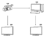
図1は本発明の第1の実施形態における画像処理システムの構成を示す構成図である。図1に示すように、画像処理システムは、撮像装置であるデジタルカメラ100、画像を表示するモニタ200、画像に対して色・輝度の補正などの画像加工処理を施すカラーグレーディング装置300(画像処理装置)を含む。
<First Embodiment>
FIG. 1 is a block diagram showing the configuration of the image processing system in the first embodiment of the present invention. As shown in FIG. 1, an image processing system includes a
カメラ100は、被写体を撮影し、撮影した画像の画像データを記録媒体に記録するとともに、撮影中の撮影画像をモニタ200に出力する。撮影完了後にカラーグレーディング装置300は、記録媒体に記録された画像データを読み込み、読み込んだ画像に対してカラーグレーディング処理を行う。また、カラーグレーディング装置300は、カラーグレーディング結果の画像等をモニタ200へ出力する。なお、カメラ100に接続されるモニタ200とカラーグレーディング装置300に接続されるモニタ200は、それぞれ異なるモニタであっても、または同一のモニタを用いても構わない。
The
図2はデジタルカメラ100の構成を示すブロック図である。図2を参照して、デジタルカメラ100における被写体撮影時の基本的な処理の流れについて説明する。撮像部103は、光学像を電気信号に変換するCCDやCMOS素子等で構成され、ズームレンズ、フォーカスレンズを含むレンズ群101及びシャッター102を介して入射した光を光電変換し、入力画像信号としてA/D変換器104へ出力する。A/D変換器104は撮像部103から出力されるアナログ画像信号をデジタル画像信号に変換し、画像処理部105に出力する。
FIG. 2 is a block diagram showing the configuration of the
画像処理部105は、A/D変換器104からの画像データ、または、メモリ制御部107を介して画像メモリ106から読み出した画像データに対し、ホワイトバランス処理などの色変換処理、γ処理、色補正処理などの各種画像処理を行う。なお、画像処理部105で行われる処理の詳細については後述する。また、画像処理部105では、撮像した画像データを用いて所定の演算処理を行い、得られた演算結果に基づいてシステム制御部50が露光制御、合焦制御を行う。これにより、TTL(スルー・ザ・レンズ)方式のAF(オートフォーカス)処理、AE(自動露出)処理などを行う。また、画像処理部105は上述したホワイトバランス処理として、撮像した画像データを用いて後述する処理により光源を推定し、推定した光源に基づくAWB(オートホワイトバランス)処理を行う。
The
画像処理部105から出力された画像データは、メモリ制御部107を介して画像メモリ106に書き込まれる。画像メモリ106は、撮像部103から出力された画像データや、表示部109に表示するための画像データを格納する。
The image data output from the
D/A変換器108は、画像メモリ106に格納されている表示用の画像データをアナログ信号に変換して表示部109に供給し、表示部109はLCD等の表示器上に、D/A変換器108からのアナログ信号に応じた表示を行う。また、画像メモリ106に格納されている画像データは外部出力インタフェース(I/F)113を介して、外部のモニタ200にも出力することができる。
The D /
コーデック部110は、画像メモリ106に記憶された画像データをMPEGなどの規格に基づきそれぞれ圧縮符号化する。システム制御部50は符号化した画像データもしくは、非圧縮の画像データを、インタフェース(I/F)111を介して、メモリカードやハードディスク等の記録媒体112に格納する。また、コーデック部110は、記録媒体112から読み出した画像データが圧縮されていた場合に、復号化して画像メモリ106に格納する。
The
上記の基本動作以外に、システム制御部50は、不揮発性メモリ124に記録されたプログラムを実行することで、後述する第1の実施形態の各処理を実現する。なお、不揮発性メモリ124は電気的に消去・記録可能であって、例えばEEPROM等が用いられる。また、ここでいうプログラムとは、第1の実施形態で後述する各種フローチャートを実行するためのプログラムのことである。この際、システム制御部50の動作用の定数、変数、不揮発性メモリ124から読み出したプログラム等をシステムメモリ126に展開する。
In addition to the above basic operation, the
また、図2に示すようにカメラ100は、各種の操作指示を入力するための操作部120、電源スイッチ121、電池の装着の有無、電池の種類、電池残量など、電源部123の状態を検出する電源制御部122を含む。更に、各種制御に用いる時間や、内蔵された時計の時間を計測するシステムタイマ125を有する。
In addition, as shown in FIG. 2, the
図3は、画像処理部105の構成を示すブロック図である。図3を参照して、画像処理部105で行われる本第1の実施形態における処理について説明する。図3に示すように、図2のA/D変換器104から画像信号が画像処理部105に入力される。画像処理部105に入力された画像信号は、ベイヤー配列のRGB画像データで、色信号生成部1051に入力される。一方で、ベイヤーRGB形式(RAW形式)のまま画像を記録する場合、画像処理部105は入力した画像信号をそのまま出力する。出力された画像信号はI/F111を介して記録媒体112に記録することができる。色信号生成部1051は入力されたベイヤー配列のRGB画像データから、全画素それぞれについてR、G、Bの色信号を生成する。色信号生成部1051は、生成した色信号R、G、BをWB増幅部1052へ出力する。
FIG. 3 is a block diagram illustrating a configuration of the
WB増幅部1052は、システム制御部50が算出するホワイトバランスゲイン値に基づき、色信号R、G、Bにそれぞれゲインをかけ、ホワイトバランスを調整する。色補正処理部1053では、ホワイトバランス処理された色信号R、G、Bに対して、3×3のマトリクス処理や3次元のLUT(Look Up Table)処理を行い、色調を補正する。更に、ガンマ処理部1054では、Rec.709などの規格に沿ったガンマやログ形式のガンマを掛けるなどのガンマ補正を行い、輝度・色差信号生成部1055では、色信号R、G、Bから輝度信号Y、色差信号R−Y、B−Yを生成する。輝度・色差信号生成部1055は、生成した輝度信号Y、色差信号R−Y、B−YをI/F111へ出力する。出力された輝度・色差信号は、I/F111を介して記録媒体112に記録することができる。
Based on the white balance gain value calculated by the
一方、WB増幅部1052はホワイトバランス処理後の色信号R、G、Bを色空間変換部1056にも出力する。色空間変換部1056は入力された色信号R、G、Bを所定の規格のRGB値に変換する。本第1の実施形態では、映画芸術科学アカデミー(AMPAS)が提案しているACES(Academy Color Encode Specification)規格の色空間へ変換するものとするが、本発明はこの規格に限られるものではない。ACES色空間への変換は、色信号R、G、Bに対して3×3のマトリクス演算(M1)を行うことで可能である。ただし、ACES空間は浮動小数点で表現されるが、ここでは、例えば値を1000倍するなどして、整数値で処理する。色空間変換部1056は変換後のRGB値(ACES_RGB信号)を色補正部1057へ出力する。色補正部1057は、ACES_RGB信号に対して、3×3のマトリクス処理を行う。ここでは、色補正部1057でかける3×3のマトリクスをM2と表す。このマトリクスM2は、後述するユーザ操作によって行われるカラーグレーディング処理によって決定される。更に、ガンマ処理部1058は、設定したガンマパラメータγ1に従って、ガンマ変換処理をRGB信号に対して行い、ガンマ変換後の画像信号を外部出力I/F113を介してモニタ200へ出力する。なお、ここで行われるガンマ処理の特性は、後述するユーザ操作によって行われるカラーグレーディング処理によって決定される。
On the other hand, the
次に、システム制御部50が、撮影画像の記録前に、画像処理部105のパラメータを設定する際の処理について図4のフローチャートを用いて説明する。まずS400では、操作部120に対するユーザからの操作入力情報を受信する。受信した情報に従って、色補正部1057のマトリクスM2及びガンマ処理部1058のパラメータγ1を決定する。ユーザは、モニタ200に表示された映像を見ながら操作部120を操作し、所望の画質となるようにマトリクスM2及びガンマγ1を設定する。このとき、操作部120は、直接、マトリクスM2及びガンマγ1の数値入力を受け付けることも可能であるし、予め用意されたマトリクスM2及びガンマγ1を表示し、ユーザからの選択を受け付けることも可能である。
Next, processing when the
S401では、ユーザ入力によって設定されたパラメータ(第1の処理情報)を各処理部に設定する。具体的には、色補正部1057に対してユーザ入力操作によって指定されたマトリクスM2のパラメータを設定する。また、ガンマ処理部1058に対してユーザ入力操作によって指定されたγ1のパラメータを設定する。
In S401, a parameter (first processing information) set by user input is set in each processing unit. Specifically, the parameters of the matrix M2 designated by the user input operation are set to the
S402では、S401で設定したマトリクスM2及びγ1が基準となるマトリクスと差があるか否かを判定する。具体的には、マトリクスM2が基準となる所定のマトリクスM3(ここでは、M3はACESで定める目標値に合わせるマトリクス)と差があるかを判定する。また、ガンマに関してもγ1が基準となる所定のガンマγ2(ここではγ2=0.45)と比較して差があるのかを判定する。差がある場合は、S403に進み、差がない場合は処理を終了する。 In S402, it is determined whether or not the matrices M2 and γ1 set in S401 are different from the reference matrix. Specifically, it is determined whether or not there is a difference from a predetermined matrix M3 (here, M3 is a matrix adjusted to a target value defined by ACES) based on the matrix M2. Further, regarding gamma, it is determined whether there is a difference compared with a predetermined gamma γ2 (here, γ2 = 0.45) with γ1 as a reference. If there is a difference, the process proceeds to S403, and if there is no difference, the process ends.
S403では、外部出力I/F113からモニタ200の接続情報を得、S404では、S403で取得したモニタ接続情報を判定する。モニタ200と接続されている場合はS405に進み、接続されていない場合は処理を終了する。
In S403, connection information of the
S405では、撮影記録後にカラーグレーディング装置300で利用するカラーグレーディング用のパラメータを生成する。この処理では、色補正部1057及びガンマ処理部1058に設定したパラメータからカラーグレーディング用のパラメータを生成する。具体的には、基準となるパラメータ(マトリクスM3及びγ2)(第2の処理情報)と、ユーザが指定したパラメータ(マトリクスM2及びγ1)の差分情報を生成し、これをカラーグレーディング用のパラメータとする。
In step S405, color grading parameters used by the
まず、マトリクスについて説明すると、ユーザが指定したマトリクスM2は以下の式で表現できるものとする。
M2 = M3 × M4
First, the matrix will be described. The matrix M2 designated by the user can be expressed by the following equation.
M2 = M3 × M4
これは、色補正部1057に設定されたマトリクスM2は、ACESで定める目標値への変換処理マトリクスM3と、ACESの目標値からユーザが所望とする色への変換処理マトリクスM4から構成されることを示している。このように、ユーザ操作によって指定されたマトリクスM2からマトリクスM4を生成する。つまり、M3の逆マトリクスをM2にかけることでマトリクスM4を得る。
ガンマ処理部1058も同様に、設定したガンマγ1ではなく、ガンマのかかっていないリニアな状態からガンマγ1を用いて処理した後の状態への変換を示すガンマγ3を算出し、γ3のパラメータをカラーグレーディング用のパラメータとする。具体的には、ユーザによって設定されたγ1に対して、基準ガンマγ2(例えば、0.45)の逆ガンマをガンマγ1にかけることでγ3を得る。以上のようにして、カラーグレーディング用のパラメータ(M4及びγ3)を生成する。
This is because the matrix M2 set in the
Similarly, the
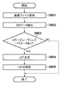
次に、カメラ100において上記のようにしてユーザ設定に基いて生成したカラーグレーディング用のパラメータ(M4及びγ3)を、撮影時に撮影画像のメタデータとして画像データに関連付けて記録する処理について説明する。図5は撮影時のシステム制御部50の処理フローを示している。
Next, a process of recording the color grading parameters (M4 and γ3) generated based on the user settings in the
ユーザによる操作部120への操作により画像記録開始が指示されると、S500では、撮影画像と共に記録するメタデータを生成する。ここでは、撮影しているカメラのメーカー名や撮影日時、画像サイズなどをメタデータとして生成する。また、図5に示した処理で生成したカラーグレーディング用のパラメータもメタデータとして生成する。
When an image recording start is instructed by a user operation on the
ここで、メタデータを含む画像ファイルの例を図6に示す。図6はカメラ100で記録するファイル構成を示している。画像ファイル600は、メタデータ601及び各フレームの画像データ610を含んでいる。図6に示すように本第1の実施形態では、画像ファイル600のヘッダ部にメタデータ601を記録し、メタデータ601の中には、カラーグレーディング用のパラメータ602が含まれている。
Here, an example of an image file including metadata is shown in FIG. FIG. 6 shows a file structure recorded by the
S501では画像データを記録メディアに記録する。その際、図6に示すような画像ファイル600を生成し、そのヘッダ部にメタデータ601を記録する。そして、ヘッダ部に続いて、撮影した画像の画像データ610を1フレーム毎に記録する。
In step S501, image data is recorded on a recording medium. At that time, an
S502では、ユーザによる操作部120への操作情報に基づき、画像記録終了が指示されたか否かを判定する。画像記録終了が指示がされた場合はS503へ進み、生成中のファイル600をクローズし、1つのファイルとして記録媒体112への記録を終了する。
In S <b> 502, it is determined whether or not an end of image recording is instructed based on operation information on the
一方、画像記録終了が指示がされていない場合はS504へ進み、ユーザによる操作部120への操作情報に基づき、画像処理部105に対するパラメータ(M2及びγ1)に変更があったか否かを判定する。変更があった場合はS505に進み、変更がない場合はS501へ戻る。
On the other hand, if the end of image recording has not been instructed, the process proceeds to S504, where it is determined whether or not the parameters (M2 and γ1) for the
S505では生成中の画像ファイル600をクローズし、1つのファイルとして記録媒体112への記録を終了する。S506では、カラーグレーディング用のパラメータを再度生成する。即ち、図4のS405で説明した処理と同様の処理を行い、ユーザ操作によって変更されたマトリクスM2及びガンマγ1に基づきカラーグレーディング用のパラメータ(M4、γ3)を生成する。カラーグレーディング用のパラメータを生成した後はS500に戻り、変更後のメタデータ601を含む新たな画像ファイル600を生成する。
In step S505, the
以上のように記録制御することで、カラーグレーディング用のパラメータに変更がない限りは、1ショットの記録に対して1つの画像ファイルが生成される。また、カラーグレーディング用のパラメータに変更があった場合は、画像ファイル600を新たに生成する。即ち、カラーグレーディング用のパラメータは各画像ファイル600において共通のものとなる。
By controlling the recording as described above, one image file is generated for one shot recording unless the color grading parameters are changed. When the color grading parameters are changed, an
次に、撮影時に上記のようにカメラ100で記録された画像データを、撮影記録後にカラーグレーディング装置300でカラーグレーディング処理する場合について説明する。図7はカラーグレーディング装置300の構成を示すブロック図である。まず、図7を参照して、カラーグレーディング装置300における画像処理の基本的な処理の流れについて説明する。ここでは、カメラ100で記録媒体112に記録した画像データを読み込み、画像処理する流れを説明する。
Next, a case will be described in which the image data recorded by the
システム制御部350は、ユーザによりマウスやキーボード、タッチパネルなどから構成される操作部320の操作によって、記録媒体112からの画像読み込みを受け付ける。これに応じて、記録インタフェース(I/F)302を介して、カラーグレーディング装置300に着脱可能な記録媒体112に記録された画像データを画像メモリ303へ読み込む。また、システム制御部350は、記録媒体112から読み込んだ画像データが圧縮符号化されたデータの場合は、画像メモリ303の画像データをコーデック部304へ渡す。コーデック部304は、圧縮符号化された画像データを復号し、復号した画像データを画像メモリ303へ出力する。システム制御部350は画像メモリ303に蓄積した復号後の画像データ、もしくは、ベイヤーRGB形式(RAW形式)など非圧縮の画像データを画像処理部305へ出力する。
The
システム制御部350は、後述する処理によって画像処理部305で用いるパラメータを決定し、画像処理部305へパラメータを設定する。画像処理部305は、設定されたパラメータに従って画像処理を行い、画像処理結果を画像メモリ303に格納する。また、システム制御部350は、画像処理後の画像を画像メモリ303から読み出し、外部モニタインタフェース(I/F)306を介して、モニタ200へ出力する。
The
なお、図7に示すように、カラーグレーディング装置300は電源スイッチ321、電源部322、電気的に消去・記録可能な不揮発性メモリ323、各種制御に用いる時間や、内蔵された時計の時間を計測するシステムタイマ324を含む。更に、システム制御部350の動作用の定数、変数、不揮発性メモリ323から読みだしたプログラム等を展開するシステムメモリ325を有する。
As shown in FIG. 7, the
次に、システム制御部350において、画像処理部305のパラメータを決定する際の第1の実施形態における処理の流れを図8のフローチャートを用いて説明する。S801において、記録媒体112から読み出した画像ファイル600を画像メモリ303に書き込み、S802において画像ファイル600のヘッダに記録されたメタデータ601を抽出する。
Next, the flow of processing in the first embodiment when the parameters of the
S803ではメタデータ601を解析し、カラーグレーディング用のパラメータ602(M4及びγ3)が記録されているか否かを判定する。カラーグレーディング用のパラメータ602が記載されている場合はS804に進み、記載されていない場合は、処理を終了する。
In step S803, the
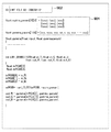
S804では、カラーグレーディング用のパラメータ602に従ってLMT(Look Modification Transform)ファイルを生成する。LMTファイルとは、画像処理の内容を記載したファイルであり、第1の実施形態では、映画芸術科学アカデミー(AMPAS)が提案している記述言語であるCTL(Color Transform Language)形式でLMTファイルを生成する。ここで、生成したLMTファイルの例を図9に示す。CTLはインタプリタ型の言語であり、記載の命令に従った画像処理を入力画像ファイルに対してかけることが可能である。
In step S804, an LMT (Look Modification Transform) file is generated according to the
図8に戻り、S805ではLMTファイルを画像処理部305に設定する。画像処理部305は、後述のとおり、設定されたLMTファイルに記述された画像処理を実行する。
Returning to FIG. 8, in step S805, the LMT file is set in the
次に、カラーグレーディング装置300の画像処理部305で行われる本第1の実施形態における処理について説明する。図10は画像処理部305の詳細を示すブロック図である。ここでは、画像処理部305への入力画像がベイヤーRGB形式(RAW形式)の画像データである場合を例に説明する。
Next, processing in the first embodiment performed by the
図10に示すように、ベイヤーRGB形式(RAW形式)の画像データは、システム制御部350の制御によって、RGB信号生成部1001に入力される。RGB信号生成部1001はベイヤーRGB形式(RAW形式)の画像データに対してディベイヤー処理を行い、RGB信号を生成する。そして、生成したRGB信号をIDT(Input Device Transform)処理部1002に出力する。IDT処理部1002は入力されたRGB信号をACES規格のACES_RGB色空間信号に変換する処理と、ACES規格が定める色目標値に補正する処理の2つを行う。ここで、ACES規格のACES_RGB色空間信号に変換する処理とは、上述した図3の色空間変換部1056のマトリクス演算(M1)と等価なものである。ただし、マトリクス演算M1は整数演算だが、ここでは、ACES規格に基づいた浮動小数点の演算を行う。また、ACES規格が定める色目標値に補正する処理とは、基準となるパラメータであるマトリクスM3と等価なものである。即ち、IDT処理部1002は、マトリクスM1とM3の処理を行い、入力RGB値をACES規格のRGB値に変換する。このようにして生成したACES_RGBデータをLMT処理部1003へ出力する。
As illustrated in FIG. 10, image data in the Bayer RGB format (RAW format) is input to the RGB
LMT処理部1003では、設定されたLMTファイルに従った画像処理を行う。LMTファイルが設定されていない場合は、何も処理を行わずに画像データを出力する。LMTファイルが設定されている場合は、LMTファイルを解釈し、記載内容に従った処理を行う。例えば図9に示すLMTファイルの場合は、3×3のマトリクスM4の処理及びガンマγ3の処理を行う。LMT処理部1003は画像処理後のACES_RGB画像データを基準ガンマ処理部1004へ出力する。基準ガンマ処理部1004は、モニタ200の規格に応じたガンマ処理を施す。例えば、モニタ200がRec.709準拠のモニタの場合は、モニタガンマの逆数(1/2.2もしくは1/2.4)のガンマ処理を行い、ガンマ処理後のRGB値を整数化する。そして、基準ガンマ処理部1004はRGB値を外部モニタI/F306を介してモニタ200へ出力する。
The
以上説明したとおり、本第1の実施形態では、カメラ100において基準状態(ACESの色空間及び色目標値)に対するカラーグレーディング用のパラメータ(マトリクスM4,ガンマγ3)を生成する。そして、生成したカラーグレーディング用のパラメータを、画像データに関連付けて記録する構成とした。
As described above, in the first embodiment, the
また、カラーグレーディング装置300では、読み込んだ画像をIDT処理部1002で一度、基準状態(ACES規格の色空間及び色目標値)に変換する。そして、基準状態に対するカラーグレーディング用のパラメータ(M4、γ3)処理を行う構成とした。このように、基準状態に対するカラーグレーディングのパラメータを受け渡しすることで、記録された画像と、撮影時の画像の状態が異なっていても、撮影時のカラーグレーディングを、撮影記録後に再現することが可能となる。
In the
なお、第1の実施形態では図3に示すように、色空間変換部1056と色補正部1057とを分けて記載したが、実際のマトリクス演算は1つの回路で行ってもよい。この場合、回路に設定するマトリクスは、M1×M2となるが、カラーグレーディング用のマトリクスパラメータとしては前述と同様にM4を生成し、メタデータとして記録する。
In the first embodiment, as shown in FIG. 3, the color
また、第1の実施形態では、カラーグレーディング用のパラメータとして、3×3マトリクス及びガンマ特性を用いる場合を例に説明したが、画像処理のパラメータであればこれら以外のパラメータを利用してもかまわない。例えば、1次元や3次元のルックアップテーブルをパラメータとして使用してもよいし、RGB値に対するゲイン値や、オフセット値をパラメータとして使用する構成をとってもよい。 In the first embodiment, the case where a 3 × 3 matrix and gamma characteristics are used as the parameters for color grading has been described as an example. However, other parameters may be used as long as they are image processing parameters. Absent. For example, a one-dimensional or three-dimensional lookup table may be used as a parameter, or a configuration using a gain value or an offset value for RGB values as a parameter may be employed.
また、第1の実施形態では、カメラ100からモニタ200に出力する際に、ガンマ処理部1058の出力画像をモニタ200に出力する構成をとっているが、本発明はこれに限定されるものではない。例えば、ガンマ処理部1058の後段に、映画芸術科学アカデミー(AMPAS)が提案しているRRT処理、ODT処理を行った後のデータを出力してもよい。ここで、RRT(Reference Rendering Transform)処理とは、基準となるフィルム調の画作りを行う処理である。また、ODT(Output Device Transform)処理とは、出力デバイスに応じたガンマ及び色空間変換を行う処理である。この場合、カラーグレーディング装置300においても図10の基準ガンマ処理部1004による処理の代わりにRRT処理及びODT処理を行う構成とする。
In the first embodiment, when the
また、第1の実施形態では、基準状態としてACES規格を例に説明したが、ある基準状態における変換もしくはカラーグレーディング用のパラメータを生成する形態であればACES以外のどのような状態を利用してもかまわない。例えば色空間がAdobeRGBで、被写体に忠実な色再現におけるカラーグレーディング用のパラメータを生成し、それをメタデータとして記録してもよい。 In the first embodiment, the ACES standard has been described as an example of the reference state. However, any state other than ACES can be used as long as a conversion or color grading parameter is generated in a certain reference state. It doesn't matter. For example, the color space may be AdobeRGB, and parameters for color grading in color reproduction faithful to the subject may be generated and recorded as metadata.
また、第1の実施形態では、カラーグレーディング装置300がベイヤーRGB形式(RAW形式)の画像データを読み込んだ場合を例に説明したが、それ以外の画像フォーマットで記録されたデータに対しても対応が可能である。例として、図3に示すカメラ100の輝度・色差信号生成部1055から出力した輝度・色差データ(Y、R−Y、B−Y)を入力とした場合について図10を参照して説明する。輝度・色差データは、カラーグレーディング装置300の画像処理部305のRGB変換処理部1005に入力される。RGB変換処理部1005で輝度・色差データをRGBデータに変換し、デガンマ処理部1006に出力する。
In the first embodiment, the case where the
デガンマ処理部1006は、カメラ100のガンマ処理部1054で掛けられたガンマ処理の逆のガンマ処理を施す。デガンマ処理部1006はRGBデータをIDT処理部1002へ出力する。IDT処理部の処理は前述と同様であり、ACESの色空間へ変換する処理及びACESの目標値へ変換する処理となる。ここで、ACESの目標値へ変換する処理は、前述のベイヤーRGB形式(RAW形式)の画像データの場合とは異なる値を用いる。
The
<第2の実施形態>
次に、本発明の第2の実施形態を説明する。第2の実施形態では、画像記録時にLMTファイルを生成する場合の例について説明する。なお、第2の実施形態におけるシステム構成及び各装置の構成は第1の実施形態で図1、図2、図3、図7、図10を参照して説明したものと同様であるため、ここでは説明を省略する。また、図4に示すように、撮影開始前に設定したパラメータに基づきカラーグレーディング用のパラメータを生成する点も第1の実施形態で図4を参照して説明した処理と同様である。
<Second Embodiment>
Next, a second embodiment of the present invention will be described. In the second embodiment, an example in which an LMT file is generated during image recording will be described. The system configuration and the configuration of each device in the second embodiment are the same as those described with reference to FIGS. 1, 2, 3, 7, and 10 in the first embodiment. Then, explanation is omitted. In addition, as shown in FIG. 4, the color grading parameters are generated based on the parameters set before the start of photographing, which is the same as the processing described with reference to FIG.
第2の実施形態は、撮影画像の記録時におけるカメラ100のシステム制御部50の動作及びカラーグレーディング装置300での処理が第1の実施形態と異なる。具体的には、カメラ100において、図11のフローチャートに示す処理が、第1の実施形態で図5を参照して説明した処理の代わりに行われるとともに、図6に示す画像ファイルの代わりに、図12に示すものが記録される。更に、カラーグレーディング装置300において、図8に示す処理の代わりに、図13に示す処理が行われる。従って、以下、これらの相違点について説明する。
The second embodiment is different from the first embodiment in the operation of the
S1100ではLMTファイルを生成する。ここでは、生成されたカラーグレーディング用のパラメータ(M4、γ3)に基づき、図9に示すようなLMTファイル形式で記述したファイルを生成する。この場合、予めLMTファイルのテンプレートを保持しておき、パラメータ部分(図9の901)のみを上書きするようにする。また、生成したLMTファイル(第3の処理情報)には固有のID(リンク情報)(図9の902)を割り振る。 In S1100, an LMT file is generated. Here, based on the generated color grading parameters (M4, γ3), a file described in the LMT file format as shown in FIG. 9 is generated. In this case, an LMT file template is stored in advance, and only the parameter portion (901 in FIG. 9) is overwritten. Further, a unique ID (link information) (902 in FIG. 9) is assigned to the generated LMT file (third processing information).
ここで、LMTファイルのIDを含む画像ファイルの例を図12に示す。図12に示すように、画像ファイル1200は、ファイルヘッダ1201及び各フレームの画像データ1210を含み、画像データ1210は、生成したLMTファイルのIDをメタデータとして付加したフレームヘッダ1211を含む。図12では、フレームNo.0〜フレームNo.5599のフレームにIDが00000112のLMTファイルを関連付けた例を示している。
Here, an example of an image file including the ID of the LMT file is shown in FIG. As shown in FIG. 12, the
S1101では、画像データをI/F111を介して、記録媒体112に記録する。その際、図12に示すような画像ファイル1200を生成し、各フレームの画像データ1210を記録する際に、そのフレームヘッダ1211に生成したLMTファイルのIDをメタデータとして付加する。
In S1101, the image data is recorded on the
S1102では、ユーザによる操作部120への操作情報に基づき、画像記録終了が指示されたか否かを判定する。画像記録終了が指示がされた場合はS1103へ進み、生成中のファイル1200をクローズし、1つのファイルとして記録媒体112への記録を終了する。
In step S1102, it is determined based on operation information on the
一方、画像記録終了が指示されていない場合はS1104へ進み、ユーザによる操作部120への操作情報に基づき、画像処理部105に対するパラメータに変更があったか否かを判定する。変更があった場合はS1105に進み、変更がない場合は、S1101に戻り、次のフレームの画像データの記録処理を行う。
On the other hand, if the end of image recording is not instructed, the process advances to step S1104, and it is determined whether or not the parameter for the
S1105ではカラーグレーディング用のパラメータを再度生成する。ここでは、第1の実施形態で図4のS405で説明した処理と同様の処理を行う。即ち、画像処理部105に設定された画像処理のパラメータからカラーグレーディング用のパラメータを生成する。カラーグレーディング用のパラメータを生成した後はS1100に戻り、変更後のカラーグレーディング用のパラメータに基づきLMTファイルを生成する。そして新たに生成したLMTファイルに新たなIDを付与する。
In S1105, parameters for color grading are generated again. Here, the same processing as that described in S405 of FIG. 4 in the first embodiment is performed. That is, color grading parameters are generated from the image processing parameters set in the
図12は、画像フレームNo.5600からカラーグレーディング用のパラメータが変更された例を示している。この例では、画像フレームNo.5600〜画像フレームNo.NまでのフレームにIDが00000113のLMTファイルを関連付けた例を示している。 FIG. 12 shows an image frame No. An example in which the parameter for color grading is changed from 5600 is shown. In this example, the image frame No. 5600 to image frame no. An example in which an LMT file with ID 00000113 is associated with up to N frames is shown.
次に、撮影時に上記のようにカメラ100で記録された画像データを、撮影記録後にカラーグレーディング装置300でカラーグレーディング処理する場合に、画像処理部305のパラメータを決定する際の第2の実施形態における処理の流れを説明する。ここでは図13のフローチャートに示す処理を行うが、この図13に示す処理は、第1の実施形態で図8を参照して説明した処理の代わりに行われる。
Next, a second embodiment for determining parameters of the
S1301において、記録媒体112から、画像ファイル1200に含まれる1フレーム分の画像データ1210を画像メモリ303に書き込み、S1302において、画像データ1210のフレームヘッダ1211を抽出する。
In step S1301, the
S1303では、フレームヘッダ1211にLMTファイルのIDが記載されているか判定する。LMTファイルのIDが記載されている場合はS1304に進み、記載されていない場合はS1305に進む。S1304では、記載されたLMTのIDに対応したLMTファイルを読み込み、読み込んだLMTファイルを画像処理部305に設定する。
In step S1303, it is determined whether the ID of the LMT file is described in the
S1305では、現在処理中の画像データ1210で画像ファイルが終了するか否かを判定する。ファイル終了の場合は、処理も終了する。一方、ファイルが終了しない場合は、次のフレームの画像データ1210を読み込み、新たな画像データ1210に対してS1302以降の処理を行う。
In step S1305, it is determined whether the image file ends with the
なお、設定されたLMTファイルに従い、画像処理部305が行う処理に関しては、第1の実施形態と同様であるため説明は省略する。
Note that the processing performed by the
上記の通り本第2の実施形態によれば、LMTファイルをカメラ100で生成し、そのLMTファイルを指定する情報を画像データに記録する構成とした。これにより、カラーグレーディング装置でLMTファイルを生成する必要がなくなり、LMTを生成することができないカラーグレーディング装置でも、撮影時のカラーグレーディングを再現することが容易となる。また、LMTファイルを生成することで、カラーグレーディングの処理内容と処理パラメータだけでなく、処理の順序を規定することが可能となる。
As described above, according to the second embodiment, an LMT file is generated by the
なお、本第2の実施形態では、生成したLMTファイルのID情報を全てのフレームヘッダに記載する構成としたが、画像データとLMTファイルが関連付けられているのであればどのような形態をとっても構わない。例えば、生成したLMTファイルをファイルヘッダに埋め込む構成をとっても構わない。この場合、LMTファイルが複数ある場合は、複数のLMTファイルをファイルヘッダに埋め込む。このようにLMTファイルを画像ファイルヘッダに埋め込むことで、ユーザがLMTファイルだけを紛失してしまい、撮影時のカラーグレーディングを再現できないということを低減させることが可能である。 In the second embodiment, the ID information of the generated LMT file is described in all the frame headers. However, any form may be used as long as the image data and the LMT file are associated with each other. Absent. For example, the generated LMT file may be embedded in the file header. In this case, when there are a plurality of LMT files, the plurality of LMT files are embedded in the file header. By embedding the LMT file in the image file header in this way, it is possible to reduce that the user loses only the LMT file and cannot reproduce color grading at the time of shooting.
<他の実施形態>
上述した第1の実施形態では、カラーグレーディング用のパラメータを撮影画像のメタデータとして記録する場合を例に説明したが、撮影画像に関連付けられるのであればどのような形態でカラーグレーディング用のパラメータを記録してもかまわない。例えば、カメラ100でカラーグレーディング用のパラメータをLMTファイルとして生成し、LMTファイルへのリンク情報を画像ファイルのメタデータとして記録しておいてもよい。具体的には、LMTファイルを生成する際に固有のID番号を振り、そのID番号を撮影画像のメタデータとして記録する方法をとることが可能である。もしくは、カメラ100が図示しない通信部を介して、LMTファイルを外部のサーバに送信し、送信先のサーバのURL情報などを記録画像のメタデータとして記録する構成をとってもよい。また、LMTファイルそのものをメタデータとして画像ファイルに記録してもよい。
<Other embodiments>
In the first embodiment described above, the case where the color grading parameters are recorded as the metadata of the captured image has been described as an example. However, the color grading parameters can be set in any form as long as they are associated with the captured image. You can record it. For example, color grading parameters may be generated by the
また、上述した第2の実施形態では、生成したLMTファイルのID情報を全てのフレームヘッダに記載する構成としたが、カラーグレーディング用のパラメータを全てのフレームヘッダに記録するようにしてもよい。その場合、カラーグレーディング装置は各フレームの画像データのフレームヘッダに含まれるカラーグレーディング用のパラメータを読み出し、それに基づいて第1の実施形態で説明したようにしてLMTファイルを生成すれば良い。 In the second embodiment described above, the ID information of the generated LMT file is described in all frame headers. However, color grading parameters may be recorded in all frame headers. In that case, the color grading apparatus may read out the parameters for color grading included in the frame header of the image data of each frame and generate an LMT file based on the parameters as described in the first embodiment.
また、本発明は、以下の処理を実行することによっても実現される。即ち、上述した実施形態の機能を実現するソフトウェア(プログラム)を、ネットワーク又は各種記憶媒体を介してシステム或いは装置に供給し、そのシステム或いは装置のコンピュータ(またはCPUやMPU等)がプログラムを読み出して実行する処理である。 The present invention can also be realized by executing the following processing. That is, software (program) that realizes the functions of the above-described embodiments is supplied to a system or apparatus via a network or various storage media, and a computer (or CPU, MPU, or the like) of the system or apparatus reads the program. It is a process to be executed.
Claims (7)
ユーザからの指示に基づく第1の処理情報に応じて、前記画像データに画像処理を行う処理手段と、
前記第1の処理情報と、前記画像データを予め決められた基準状態に変換するための第2の処理情報との差分情報を取得する取得手段と、
前記取得手段により得られた差分情報を、前記画像データに関連付けて記録する記録手段と、を有し、
前記記録手段は、ユーザからの指示に基づいて前記第1の処理情報に変更が生じるまでは、変更前の第1の処理情報に対応する差分情報を変更前に撮影された画像群の画像データに共通して関連付けて1つの画像ファイルとして記録し、ユーザからの指示に基づいて前記第1の処理情報に変更が生じると、変更後の第1の処理情報に対応する差分情報を変更後に撮影された画像の画像データに関連付けて新たな1つの画像ファイルとして記録することを特徴とする撮像装置。 Imaging means for performing imaging and outputting image data;
In response to a first processing information based on the instruction from Yu chromatography The, processing means for performing image processing on the image data,
Said first processing information obtaining means for obtaining difference information between the second processing information for converting the before Symbol image data in a predetermined reference state,
Recording means for recording the difference information obtained by the acquisition means in association with the image data ;
The recording means stores the difference information corresponding to the first processing information before the change in the image data captured before the change until the first processing information is changed based on an instruction from the user. Are recorded as one image file in association with each other, and when the first processing information is changed based on an instruction from the user, the difference information corresponding to the changed first processing information is captured after the change. An image pickup apparatus that records as a new image file in association with image data of a recorded image.
処理手段が、ユーザからの指示に基づく第1の処理情報に応じて、前記画像データに画像処理を行う処理工程と、
取得手段が、前記第1の処理情報と、前記画像データを予め決められた基準状態に変換するための第2の処理情報との差分情報を取得する取得工程と、
記録手段が、前記取得工程で得られた差分情報を、前記画像データに関連付けて記録する記録工程と、を有し、
前記記録工程では、ユーザからの指示に基づいて前記第1の処理情報に変更が生じるまでは、変更前の第1の処理情報に対応する差分情報を変更前に撮影された画像群の画像データに共通して関連付けて1つの画像ファイルとして記録し、ユーザからの指示に基づいて前記第1の処理情報に変更が生じると、変更後の第1の処理情報に対応する差分情報を変更後に撮影された画像の画像データに関連付けて新たな1つの画像ファイルとして記録することを特徴とする撮像装置の制御方法。 A method for controlling an image pickup apparatus having an image pickup means for performing image pickup and outputting image data,
Processing means, the processing steps in accordance with the first processing information based on the instruction from Yu chromatography The performs image processing on the image data,
Acquisition means, said first processing information, an acquisition step of acquiring difference information between the second processing information for converting the before Symbol image data in a predetermined reference state,
A recording unit that records the difference information obtained in the acquisition step in association with the image data ;
In the recording step, until the first processing information is changed based on an instruction from the user, the difference information corresponding to the first processing information before the change is image data of the image group captured before the change. Are recorded as one image file in association with each other, and when the first processing information is changed based on an instruction from the user, the difference information corresponding to the changed first processing information is captured after the change. A method for controlling an imaging apparatus, wherein the image data is recorded as one new image file in association with the image data of the obtained image .
Priority Applications (2)
| Application Number | Priority Date | Filing Date | Title |
|---|---|---|---|
| JP2012261624A JP6049425B2 (en) | 2012-11-29 | 2012-11-29 | Imaging apparatus, image processing apparatus, and control method |
| US14/088,943 US20140147090A1 (en) | 2012-11-29 | 2013-11-25 | Image capturing apparatus, image processing apparatus, and control method therefor |
Applications Claiming Priority (1)
| Application Number | Priority Date | Filing Date | Title |
|---|---|---|---|
| JP2012261624A JP6049425B2 (en) | 2012-11-29 | 2012-11-29 | Imaging apparatus, image processing apparatus, and control method |
Publications (3)
| Publication Number | Publication Date |
|---|---|
| JP2014107837A JP2014107837A (en) | 2014-06-09 |
| JP2014107837A5 JP2014107837A5 (en) | 2016-01-21 |
| JP6049425B2 true JP6049425B2 (en) | 2016-12-21 |
Family
ID=50773379
Family Applications (1)
| Application Number | Title | Priority Date | Filing Date |
|---|---|---|---|
| JP2012261624A Active JP6049425B2 (en) | 2012-11-29 | 2012-11-29 | Imaging apparatus, image processing apparatus, and control method |
Country Status (2)
| Country | Link |
|---|---|
| US (1) | US20140147090A1 (en) |
| JP (1) | JP6049425B2 (en) |
Families Citing this family (4)
| Publication number | Priority date | Publication date | Assignee | Title |
|---|---|---|---|---|
| JP6727816B2 (en) * | 2016-01-19 | 2020-07-22 | キヤノン株式会社 | Image processing device, imaging device, image processing method, image processing program, and storage medium |
| JP6700840B2 (en) | 2016-02-18 | 2020-05-27 | キヤノン株式会社 | Image processing device, imaging device, control method, and program |
| JP6664240B2 (en) * | 2016-03-09 | 2020-03-13 | キヤノン株式会社 | Imaging system, imaging apparatus, and control method therefor |
| JP2019021159A (en) | 2017-07-20 | 2019-02-07 | キヤノン株式会社 | Image processing device and image processing method |
Family Cites Families (4)
| Publication number | Priority date | Publication date | Assignee | Title |
|---|---|---|---|---|
| JP4193378B2 (en) * | 2001-06-27 | 2008-12-10 | セイコーエプソン株式会社 | Image file generator |
| EP1389003B1 (en) * | 2002-08-08 | 2014-01-15 | Canon Kabushiki Kaisha | Color conversion table generation method and apparatus |
| US7893966B2 (en) * | 2006-06-30 | 2011-02-22 | Canon Kabushiki Kaisha | Apparatus and method for controlling editing and use of image processing parameters in image processing |
| JP4363468B2 (en) * | 2007-07-12 | 2009-11-11 | ソニー株式会社 | Imaging apparatus, imaging method, and video signal processing program |
-
2012
- 2012-11-29 JP JP2012261624A patent/JP6049425B2/en active Active
-
2013
- 2013-11-25 US US14/088,943 patent/US20140147090A1/en not_active Abandoned
Also Published As
| Publication number | Publication date |
|---|---|
| US20140147090A1 (en) | 2014-05-29 |
| JP2014107837A (en) | 2014-06-09 |
Similar Documents
| Publication | Publication Date | Title |
|---|---|---|
| JP6624889B2 (en) | Video processing apparatus, video processing method, and video processing program | |
| JP5642344B2 (en) | Image processing apparatus, image processing method, and image processing program | |
| JP2006262451A (en) | Image recording apparatus and method | |
| JP2017175319A (en) | Image processing apparatus, image processing method, and program | |
| JP6049425B2 (en) | Imaging apparatus, image processing apparatus, and control method | |
| US10009588B2 (en) | Image processing apparatus and imaging apparatus | |
| JP6057705B2 (en) | IMAGING DEVICE, IMAGING DEVICE CONTROL METHOD, AND PROGRAM | |
| JP2002305684A (en) | Imaging system and program | |
| JP6008716B2 (en) | Imaging apparatus, image processing apparatus, image processing system, and control method | |
| JP6210772B2 (en) | Information processing apparatus, imaging apparatus, control method, and program | |
| JP2004129065A (en) | Digital camera | |
| JP6257319B2 (en) | Imaging apparatus and image processing apparatus | |
| JP6576018B2 (en) | Image processing apparatus and imaging apparatus | |
| JP2018074523A (en) | Imaging device, control method thereof, program, and recording medium | |
| JP2005229280A (en) | Image processing apparatus and method, and program | |
| JP2005192197A (en) | Image pickup unit, image pickup method, recording medium, program, and display unit | |
| JP2010124114A (en) | Digital camera and image data processing program | |
| JP2020136823A (en) | Image processing device, imaging device, image processing method, control method for imaging device, and program | |
| JP5975705B2 (en) | Imaging apparatus and control method thereof, image processing apparatus, and method for image processing | |
| JP2018023033A (en) | Image data generator, image data reproduction apparatus, and image data editing device | |
| JP6083959B2 (en) | Transmission apparatus, control method thereof, and control program | |
| JP5191941B2 (en) | Imaging apparatus, image processing apparatus, image processing method, and image processing program | |
| JP6520566B2 (en) | Image recording device | |
| JP6292870B2 (en) | Image processing apparatus, image processing method, and program | |
| JP2018207418A (en) | Imaging apparatus |
Legal Events
| Date | Code | Title | Description |
|---|---|---|---|
| A521 | Request for written amendment filed |
Free format text: JAPANESE INTERMEDIATE CODE: A523 Effective date: 20151126 |
|
| A621 | Written request for application examination |
Free format text: JAPANESE INTERMEDIATE CODE: A621 Effective date: 20151126 |
|
| A977 | Report on retrieval |
Free format text: JAPANESE INTERMEDIATE CODE: A971007 Effective date: 20160812 |
|
| A131 | Notification of reasons for refusal |
Free format text: JAPANESE INTERMEDIATE CODE: A131 Effective date: 20160819 |
|
| A521 | Request for written amendment filed |
Free format text: JAPANESE INTERMEDIATE CODE: A523 Effective date: 20161003 |
|
| TRDD | Decision of grant or rejection written | ||
| A01 | Written decision to grant a patent or to grant a registration (utility model) |
Free format text: JAPANESE INTERMEDIATE CODE: A01 Effective date: 20161024 |
|
| A61 | First payment of annual fees (during grant procedure) |
Free format text: JAPANESE INTERMEDIATE CODE: A61 Effective date: 20161122 |
|
| R151 | Written notification of patent or utility model registration |
Ref document number: 6049425 Country of ref document: JP Free format text: JAPANESE INTERMEDIATE CODE: R151 |