JP6572031B2 - Capacitor - Google Patents
Capacitor Download PDFInfo
- Publication number
- JP6572031B2 JP6572031B2 JP2015137712A JP2015137712A JP6572031B2 JP 6572031 B2 JP6572031 B2 JP 6572031B2 JP 2015137712 A JP2015137712 A JP 2015137712A JP 2015137712 A JP2015137712 A JP 2015137712A JP 6572031 B2 JP6572031 B2 JP 6572031B2
- Authority
- JP
- Japan
- Prior art keywords
- suction pipe
- refrigerant
- space
- receiver
- partition member
- Prior art date
- Legal status (The legal status is an assumption and is not a legal conclusion. Google has not performed a legal analysis and makes no representation as to the accuracy of the status listed.)
- Expired - Fee Related
Links
Images


Description
この発明は、たとえばカーエアコンを構成する冷凍サイクルに用いられるコンデンサに関する。 The present invention relates to a capacitor used in a refrigeration cycle constituting a car air conditioner, for example.
この明細書および特許請求の範囲において、図1および図2の上下、左右を上下、左右というものとする。 In this specification and claims, the top and bottom, left and right in FIGS.
カーエアコンを構成する冷凍サイクルのコンデンサとして、凝縮部と、凝縮部の上方に設けられた過冷却部と、凝縮部と過冷却部との間に設けられた受液器とを備えており、凝縮部および過冷却部に、それぞれ長手方向を左右方向に向けるとともに上下方向に間隔をおいて並列状に配置された複数の熱交換管からなる少なくとも1つの熱交換パスが設けられ、凝縮部から流出した冷媒が、受液器を経て過冷却部に流入するようになっており、受液器内が、凝縮部と過冷却部との間の高さ位置に設けられた仕切部材によって、第1空間と第1空間の上方に位置する第2空間とに分割され、受液器に、第1空間に通じかつ凝縮部から冷媒が流入する冷媒流入口、および第2空間に通じかつ過冷却部に冷媒を流出させる冷媒流出口が形成され、受液器内に、下端が第1空間に開口するとともに、上端が第2空間に開口する吸い上げ管が配置され、受液器内の第1空間に、通気性および通液性を有するとともに乾燥剤が収容され、かつ長手方向が上下方向を向いた乾燥剤バッグが配置されているコンデンサが提案されている(特許文献1参照)。 As a condenser of the refrigeration cycle constituting the car air conditioner, it includes a condensing unit, a supercooling unit provided above the condensing unit, and a liquid receiver provided between the condensing unit and the supercooling unit, The condensing unit and the supercooling unit are provided with at least one heat exchanging path having a plurality of heat exchanging tubes arranged in parallel with the longitudinal direction thereof being directed in the left-right direction and spaced apart in the vertical direction. The refrigerant that has flowed out flows into the supercooling part via the liquid receiver, and the interior of the liquid receiver is provided by the partition member provided at a height position between the condensing part and the supercooling part. 1 space and the 2nd space located above the 1st space, it is divided into the liquid receiver, the 1st space and the refrigerant inflow into which the refrigerant flows in from the condensation part, and the 2nd space and the supercooling A refrigerant outlet for allowing the refrigerant to flow out is formed in Inside, a suction pipe having a lower end that opens into the first space and an upper end that opens into the second space is disposed, and the first space in the liquid receiver has air permeability and liquid permeability and accommodates a desiccant. In addition, there has been proposed a capacitor in which a desiccant bag whose longitudinal direction is directed in the vertical direction is arranged (see Patent Document 1).
特許文献1記載のコンデンサにおいては、凝縮部を通過した冷媒が冷媒流入口から受液器内の第1空間に流入した後、吸い上げ管を通って第2空間に流入し、その後冷媒流出口から過冷却部に入るようになっている。
In the capacitor described in
しかしながら、特許文献1記載のコンデンサにおいては、車両の走行時に、振動により吸い上げ管が受液器の周壁に当たり、異音が発生するという問題がある。また、受液器内に流入してきた冷媒の勢いにより乾燥剤バッグが動き、その結果乾燥剤バッグ内の乾燥剤が粉砕されて異物が発生したり、動いた乾燥剤バッグにより受液器内に流入した冷媒のスムーズな流れが阻害されたりするおそれがある。
However, the capacitor described in
この発明の目的は、上記問題を解決し、異音の発生を抑制しうるとともに、受液器内での乾燥剤バッグの動きを阻止しうるコンデンサを提供することにある。 An object of the present invention is to provide a capacitor that can solve the above-described problems, suppress the generation of abnormal noise, and prevent the movement of the desiccant bag in the liquid receiver.
本発明は、上記目的を達成するために以下の態様からなる。 In order to achieve the above object, the present invention comprises the following aspects.
1)凝縮部と、凝縮部の上方に設けられた過冷却部と、凝縮部と過冷却部との間に設けられた受液器とを備えており、凝縮部および過冷却部に、それぞれ長手方向を左右方向に向けるとともに上下方向に間隔をおいて並列状に配置された複数の熱交換管からなる少なくとも1つの熱交換パスが設けられ、凝縮部から流出した冷媒が、受液器を経て過冷却部に流入するようになっており、受液器に、凝縮部から冷媒が流入する冷媒流入口、および冷媒流入口の上方に位置しかつ過冷却部に冷媒を流出させる冷媒流出口が形成され、受液器内における冷媒流入口と冷媒流出口との間の高さ位置に、受液器内を上下に区画する仕切部材が設けられ、受液器内に、仕切部材よりも下方の冷媒流入口が通じる第1空間と、仕切部材よりも上方の冷媒流出口が通じる第2空間とが設けられ、受液器内に、下端が第1空間に開口するとともに、上端が第2空間に開口する吸い上げ管が配置され、受液器内の第1空間に、通気性および通液性を有するとともに乾燥剤が収容され、かつ長手方向が上下方向を向いた乾燥剤バッグが配置されているコンデンサにおいて、
乾燥剤バッグの外面に、上下方向にのびるとともに上下両端が開口した1つの吸い上げ管挿通用筒状部が一体に設けられ、前記吸い上げ管が乾燥剤バッグの吸い上げ管挿通用筒状部内に通されることにより、乾燥剤バッグの姿勢が保持されているコンデンサ。
1) It has a condensing part, a supercooling part provided above the condensing part, and a liquid receiver provided between the condensing part and the supercooling part. At least one heat exchange path consisting of a plurality of heat exchange tubes arranged in parallel in the vertical direction with the longitudinal direction turned to the left and right direction is provided, and the refrigerant flowing out of the condensing part The refrigerant outlet is configured to flow into the supercooling section, the refrigerant inlet into which the refrigerant flows from the condenser section, and the refrigerant outlet that is located above the refrigerant inlet and flows out of the refrigerant to the supercooling section. Is formed at a height position between the refrigerant inlet and the refrigerant outlet in the liquid receiver, and a partition member that divides the liquid receiver vertically is provided in the liquid receiver. The first space through which the lower refrigerant inlet communicates, and the refrigerant outlet above the partition member A suction pipe having a lower end that opens into the first space and an upper end that opens into the second space is disposed in the liquid receiver, and the first space in the liquid receiver is ventilated with air. In the capacitor in which the desiccant is accommodated and the desiccant is accommodated and the desiccant bag whose longitudinal direction is directed in the vertical direction is arranged,
One suction pipe insertion tubular portion extending in the vertical direction and opened at both upper and lower ends is integrally provided on the outer surface of the desiccant bag, and the suction pipe is passed through the suction pipe insertion tubular portion of the desiccant bag. Capacitor that maintains the attitude of the desiccant bag.
2)第2空間に、吸い上げ管を通って第2空間内に流入する冷媒から異物を除去するフィルタが配置されている上記1)記載のコンデンサ。 2) The capacitor according to 1) above, wherein a filter for removing foreign substances from the refrigerant flowing into the second space through the suction pipe is disposed in the second space.
3)仕切部材に吸い上げ管の上端部が挿入される貫通穴が形成され、吸い上げ管の上端部が当該貫通穴に挿入されるとともに吸い上げ管の上端開口が当該貫通穴を介して第2空間に通じており、仕切部材の上面における貫通穴の周囲の部分に、フィルタ保持部材が固定状に設けられており、フィルタ保持部材にフィルタが保持されている上記2)記載の熱交換器。 3) A through hole into which the upper end of the suction pipe is inserted is formed in the partition member, and the upper end of the suction pipe is inserted into the through hole and the upper end opening of the suction pipe is inserted into the second space through the through hole. The heat exchanger according to 2), wherein the filter holding member is fixedly provided in a portion around the through hole on the upper surface of the partition member, and the filter is held by the filter holding member.
上記1)〜3)のコンデンサによれば、乾燥剤バッグの外面に、上下方向にのびるとともに上下両端が開口した1つの吸い上げ管挿通用筒状部が一体に設けられ、前記吸い上げ管が乾燥剤バッグの吸い上げ管挿通用筒状部内に通されることにより、乾燥剤バッグの姿勢が保持されているので、吸い上げ管が直接受液器の周壁に当たることが防止され、異音の発生を抑制することができる。 According to the capacitors 1) to 3), one cylindrical portion for inserting a suction pipe that extends in the vertical direction and opens at both upper and lower ends is integrally provided on the outer surface of the desiccant bag , and the suction pipe is a desiccant. Since the posture of the desiccant bag is maintained by being passed through the cylindrical portion for inserting the suction pipe of the bag, it is possible to prevent the suction pipe from directly contacting the peripheral wall of the liquid receiver and to suppress the generation of abnormal noise. be able to.
さらに、乾燥剤バッグの吸い上げ管挿通用筒状部内に通された吸い上げ管により、受液器内に流入してきた冷媒の勢いによる乾燥剤バッグの動きが抑制される。したがって、乾燥剤バッグ内の乾燥剤が粉砕されて異物が発生することが防止されるとともに、受液器内に流入した冷媒がスムーズに流れる。 Furthermore, the movement of the desiccant bag due to the momentum of the refrigerant flowing into the liquid receiver is suppressed by the suction pipe passed through the cylindrical portion for inserting the suction pipe of the desiccant bag. Therefore, the desiccant in the desiccant bag is prevented from being crushed and foreign matters are generated, and the refrigerant flowing into the liquid receiver flows smoothly.
上記2)のコンデンサによれば、冷媒流入口から受液器内の第1空間に流入した冷媒が吸い上げ管を通って第2空間に流入する際に、フィルタにより異物が除去される。 According to the capacitor of 2), the foreign matter is removed by the filter when the refrigerant flowing into the first space in the liquid receiver from the refrigerant inlet flows into the second space through the suction pipe.
上記3)のコンデンサによれば、第2空間に、吸い上げ管を通って第2空間内に流入する冷媒から異物を除去するフィルタを比較的簡単に設けることができる。 According to the capacitor 3), it is possible to relatively easily provide a filter for removing foreign substances from the refrigerant flowing into the second space through the suction pipe in the second space.
以下、この発明の実施形態を、図面を参照して説明する。 Embodiments of the present invention will be described below with reference to the drawings.
以下の説明において、図1の紙面表裏方向(図4の上下方向)を通風方向というものとする。 In the following description, it is assumed that the front and back direction (up and down direction in FIG. 4) in FIG.
また、以下の説明において、「アルミニウム」という用語には、純アルミニウムの他にアルミニウム合金を含むものとする。 In the following description, the term “aluminum” includes aluminum alloys in addition to pure aluminum.
図1はこの発明のコンデンサの全体構成を具体的に示し、図2は図1のコンデンサを、一部の部材の図示を省略して模式的に示す。また、図3〜図5は図1のコンデンサの要部の構成を示す。 FIG. 1 specifically shows the overall configuration of the capacitor of the present invention, and FIG. 2 schematically shows the capacitor of FIG. 1 with some members omitted. 3 to 5 show the structure of the main part of the capacitor shown in FIG.
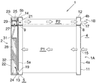
図1および図2において、コンデンサ(1)は、凝縮部(1A)と、凝縮部(1A)の上方に設けられた過冷却部(1B)と、長手方向を上下方向に向けた状態で凝縮部(1A)と過冷却部(1B)との間に設けられ、かつ気液分離機能を有するタンク状受液器(2)とを備えている。 1 and 2, the condenser (1) is condensed with the condenser (1A), the supercooling part (1B) provided above the condenser (1A), and with the longitudinal direction directed vertically. A tank-shaped liquid receiver (2) provided between the section (1A) and the supercooling section (1B) and having a gas-liquid separation function.
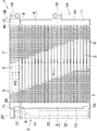
コンデンサ(1)は、幅方向を通風方向に向けるとともに長手方向を左右方向に向けた状態で上下方向に間隔をおいて配置された複数のアルミニウム製扁平状熱交換管(3)と、長手方向を上下方向に向けるとともに左右方向に間隔をおいて配置され、かつ熱交換管(3)の長手方向両端部がろう付により接続された2つのアルミニウム製ヘッダタンク(4)(5)と、隣り合う熱交換管(3)どうしの間および上下両端の熱交換管(3)の外側に配置されて熱交換管(3)にろう付されたアルミニウム製コルゲートフィン(6)と、上下両端のコルゲートフィン(6)の外側に配置されてコルゲートフィン(6)にろう付されたアルミニウム製サイドプレート(7)とを備えている。 The condenser (1) has a plurality of flat aluminum heat exchange tubes (3) arranged in the vertical direction with the width direction oriented in the ventilation direction and the longitudinal direction oriented in the left-right direction, and the longitudinal direction. Next to two aluminum header tanks (4) and (5), which are arranged in the vertical direction and spaced apart from each other in the horizontal direction, and whose longitudinal ends of the heat exchange pipe (3) are connected by brazing Aluminum corrugated fins (6) brazed to the heat exchange tubes (3) between the matching heat exchange tubes (3) and outside the heat exchange tubes (3) at the upper and lower ends, and corrugates at the upper and lower ends An aluminum side plate (7) disposed outside the fin (6) and brazed to the corrugated fin (6).
コンデンサ(1)の凝縮部(1A)には、上下に連続して並んだ複数の熱交換管(3)からなる少なくとも1つ、ここでは1つの熱交換パス(P1)が設けられている。また、コンデンサ(1)の過冷却部(1B)には、上下に連続して並んだ複数の熱交換管(3)からなる少なくとも1つ、ここでは1つの熱交換パス(P2)が設けられている。そして、各熱交換パス(P1)(P2)を構成する全ての熱交換管(3)の冷媒流れ方向が同一となっているとともに、隣り合う2つの熱交換パスの熱交換管(3)の冷媒流れ方向が異なっている。ここで、凝縮部(1A)の熱交換パス(P1)を第1熱交換パスといい、過冷却部(1B)の熱交換パス(P2)を第2熱交換パスというものとする。 The condenser (1A) of the condenser (1) is provided with at least one, here, one heat exchange path (P1) composed of a plurality of heat exchange tubes (3) arranged continuously in the vertical direction. In addition, the supercooling section (1B) of the condenser (1) is provided with at least one, in this case, one heat exchanging path (P2) composed of a plurality of heat exchanging pipes (3) arranged vertically. ing. And the refrigerant | coolant flow direction of all the heat exchange pipe | tubes (3) which comprise each heat exchange path | pass (P1) (P2) is the same, and the heat exchange pipe | tube (3) of two adjacent heat exchange paths | passes The refrigerant flow direction is different. Here, the heat exchange path (P1) of the condensing part (1A) is referred to as a first heat exchange path, and the heat exchange path (P2) of the supercooling part (1B) is referred to as a second heat exchange path.
両ヘッダタンク(4)(5)内は、それぞれ第1熱交換パス(P1)と第2熱交換パス(P2)との間の高さ位置に設けられたアルミニウム製仕切部材(8)(9)により上下方向に並んだ2つの区画(4a)(4b)(5a)(5b)に仕切られており、コンデンサ(1)における両仕切部材(8)(9)よりも下方に位置する部分が凝縮部(1A)となり、両仕切部材(8)(9)よりも上方に位置する部分が過冷却部(1B)となっている。 Both header tanks (4) and (5) have aluminum partition members (8) (9) provided at height positions between the first heat exchange path (P1) and the second heat exchange path (P2), respectively. ) Is divided into two compartments (4a), (4b), (5a), and (5b) that are lined up and down, and the part of the capacitor (1) that is located below both partition members (8) and (9) The part which becomes the condensing part (1A) and is located above both partition members (8) and (9) is the supercooling part (1B).
右側ヘッダタンク(4)における仕切部材(8)よりも下方の区画(4a)は、第1熱交換パス(P1)の熱交換管(3)の冷媒流れ方向上流側端部が通じる凝縮部入口ヘッダ部(11)となっており、同じく上方の区画(4b)は、第2熱交換パス(P2)の熱交換管(3)の冷媒流れ方向下流側端部が通じる過冷却部出口ヘッダ部(12)となっている。また、左側ヘッダタンク(5)における仕切部材(9)よりも下方の区画(5a)は、第1熱交換パス(P1)の熱交換管(3)の冷媒流れ方向下流側端部が通じる凝縮部出口ヘッダ部(13)となっており、同じく上方の区画(5b)は、第2熱交換パス(P2)の熱交換管(3)の冷媒流れ方向上流側端部が通じる過冷却部入口ヘッダ部(14)となっている。 The compartment (4a) below the partition member (8) in the right header tank (4) is a condensing part inlet through which the upstream end of the heat exchange pipe (3) of the first heat exchange path (P1) in the refrigerant flow direction communicates. The header section (11), and the upper section (4b) is also a subcooling section outlet header section that communicates with the downstream end of the heat exchange pipe (3) of the second heat exchange path (P2) in the refrigerant flow direction. (12). Further, the compartment (5a) below the partition member (9) in the left header tank (5) is condensed through the downstream end portion in the refrigerant flow direction of the heat exchange pipe (3) of the first heat exchange path (P1). The upper section (5b) is also an outlet header section (13), and the upper cooling section entrance (5b) is connected to the upstream end of the heat exchange pipe (3) of the second heat exchange path (P2) in the refrigerant flow direction. It is a header part (14).
右側ヘッダタンク(4)の凝縮部入口ヘッダ部(11)の上下方向の中間部に冷媒入口(15)が形成され、右側ヘッダタンク(4)に冷媒入口(15)に通じるアルミニウム製冷媒入口部材(16)が接合されている。また、右側ヘッダタンク(4)の過冷却部出口ヘッダ部(12)に冷媒出口(17)が形成され、右側ヘッダタンク(4)に冷媒出口(17)に通じるアルミニウム製冷媒出口部材(18)が接合されている。左側ヘッダタンク(5)の凝縮部出口ヘッダ部(13)の下端寄りの部分にヘッダ部側冷媒流出口(19)が形成され、同じく過冷却部入口ヘッダ部(14)の下側部分にヘッダ部側冷媒流入口(21)が形成されている。 An aluminum refrigerant inlet member having a refrigerant inlet (15) formed at an intermediate portion in the vertical direction of the condenser inlet header (11) of the right header tank (4) and leading to the refrigerant inlet (15) in the right header tank (4) (16) is joined. Also, a refrigerant outlet (17) is formed in the supercooling section outlet header section (12) of the right header tank (4), and an aluminum refrigerant outlet member (18) communicates with the refrigerant outlet (17) in the right header tank (4). Are joined. A header side refrigerant outlet (19) is formed in the portion near the lower end of the condensing portion outlet header portion (13) of the left header tank (5), and the header is also formed in the lower portion of the supercooling portion inlet header portion (14). A part-side refrigerant inlet (21) is formed.
図3〜図5に示すように、受液器(2)は、下端が閉鎖されるとともに上端が開口した円筒状であり、かつ左側ヘッダタンク(5)に接合された受液器本体(22)と、受液器本体(22)の上端開口を閉鎖する合成樹脂製の円柱状プラグ(23)とを備えている。受液器本体(22)の周壁の下端寄りの部分には、ヘッダ部側冷媒流出口(19)に通じる受液器側冷媒流入口(24)が形成され、同じく両ヘッダタンク(4)(5)の仕切部材(8)(9)よりも上方の高さ位置には、ヘッダ部側冷媒流入口(21)に通じる受液器側冷媒流出口(25)が形成されている。受液器本体(22)の内周面の上端部にはめねじ(22a)が形成されており、プラグ(23)の外周面の上部に形成されたおねじ(23a)が受液器本体(22)のめねじ(22a)にねじ嵌められることにより、受液器本体(22)の上端部にプラグ(23)が着脱自在に取り付けられている。なお、受液器本体(22)の内周面のめねじ(22a)よりも下方の部分と、プラグ(23)の外周面におけるおねじ(23a)よりも下方の部分とがOリング(26)によってシールされている。 As shown in FIGS. 3 to 5, the liquid receiver (2) has a cylindrical shape with the lower end closed and the upper end opened, and the liquid receiver body (22) joined to the left header tank (5). ) And a cylindrical plug (23) made of synthetic resin that closes the upper end opening of the receiver body (22). In the portion near the lower end of the peripheral wall of the receiver body (22), a receiver-side refrigerant inlet (24) leading to the header-side refrigerant outlet (19) is formed, and both header tanks (4) ( A receiver-side refrigerant outlet (25) communicating with the header-side refrigerant inlet (21) is formed at a height position above the partition members (8) and (9) in 5). A female screw (22a) is formed at the upper end of the inner peripheral surface of the receiver body (22), and the male screw (23a) formed at the upper part of the outer peripheral surface of the plug (23) is connected to the receiver body ( The plug (23) is detachably attached to the upper end of the receiver body (22) by being screwed onto the female screw (22a). A portion below the internal thread (22a) on the inner peripheral surface of the receiver body (22) and a portion below the external thread (23a) on the outer peripheral surface of the plug (23) are O-rings (26 ).
受液器(2)内における受液器側冷媒流入口(24)と同冷媒流出口(25)との間の高さ位置、たとえば第1熱交換パス(P1)と第2熱交換パス(P2)との間の高さ位置に、受液器(2)内を上下に区画する仕切部材(27)が設けられ、受液器(2)内に、仕切部材(27)よりも下方の受液器側冷媒流入口(24)が通じる第1空間(28)と、仕切部材(27)よりも上方の受液器側冷媒流出口(25)が通じる第2空間(29)とが設けられている。受液器(2)内の第1空間(28)に、下端が第1空間(28)に開口するとともに、上端が第2空間(29)に開口する吸い上げ管(31)が配置されている。また、受液器(2)内の第1空間(28)に、通気性および通液性を有するとともに乾燥剤(32a)が収容され、かつ長手方向が上下方向を向いた乾燥剤バッグ(32)が配置されている。受液器(2)内の第2空間(29)に、吸い上げ管(31)を通って第2空間(29)内に流入する冷媒から異物を除去するフィルタ(33)が配置されている。 The height position between the receiver side refrigerant inlet (24) and the refrigerant outlet (25) in the receiver (2), for example, the first heat exchange path (P1) and the second heat exchange path ( P2) is provided with a partition member (27) that divides the interior of the liquid receiver (2) up and down, and in the liquid receiver (2) below the partition member (27). A first space (28) through which the receiver-side refrigerant inlet (24) communicates and a second space (29) through which the receiver-side refrigerant outlet (25) communicates above the partition member (27) are provided. It has been. A suction pipe (31) having a lower end opened to the first space (28) and an upper end opened to the second space (29) is disposed in the first space (28) in the liquid receiver (2). . Further, a desiccant bag (32) having air permeability and liquid permeability and containing a desiccant (32a) in the first space (28) in the liquid receiver (2) and whose longitudinal direction is directed vertically. ) Is arranged. A filter (33) for removing foreign substances from the refrigerant flowing into the second space (29) through the suction pipe (31) is disposed in the second space (29) in the liquid receiver (2).
仕切部材(27)は合成樹脂製の円板状であって、その外周面と受液器(2)の受液器本体(22)の内周面との間がOリング(34)によりシールされている。仕切部材(27)の中心部には第1空間(28)と第2空間(29)とを通じさせる貫通穴(35)が形成されている。また、仕切部材(27)の上面には、フィルタ保持部材(36)が一体に形成されており、フィルタ保持部材(36)にフィルタ(33)が取り付けられている。フィルタ保持部材(36)は、仕切部材(27)の上方に間隔をおいて配置された円板(36a)と、仕切部材(27)の上面における外周縁寄りの部分に存在する1つの円周上に周方向に間隔をおいて設けられ、かつ仕切部材(27)と円板(36a)とを一体に連結する連結部(36b)とからなり、隣り合う連結部(36b)間の隙間を塞ぐようにフィルタ(33)が保持されている。 The partition member (27) is a disc shape made of synthetic resin, and the space between the outer peripheral surface and the inner peripheral surface of the receiver body (22) of the receiver (2) is sealed by an O-ring (34). Has been. A through hole (35) that allows the first space (28) and the second space (29) to pass therethrough is formed at the center of the partition member (27). A filter holding member (36) is integrally formed on the upper surface of the partition member (27), and the filter (33) is attached to the filter holding member (36). The filter holding member (36) includes a circular plate (36a) disposed above the partition member (27) at an interval, and one circumference existing in a portion near the outer peripheral edge on the upper surface of the partition member (27). It is provided with a connecting portion (36b) that is provided at an interval in the circumferential direction and connects the partition member (27) and the disk (36a) integrally, and a gap between adjacent connecting portions (36b) is formed. The filter (33) is held so as to close it.
吸い上げ管(31)の上端部は、仕切部材(27)の貫通穴(35)内に挿入されて仕切部材(27)に固定されている。吸い上げ管(31)は、上端から一定の長さを有する短垂直部(31a)と、短垂直部(31a)から下方に向かって受液器本体(22)の径方向外方に傾斜した傾斜部(31b)と、傾斜部(31b)の下端に連なって下方に真っ直ぐに延びる長垂直部(31c)とからなる。長垂直部(31c)の下端開口の周縁が傾斜面上に位置しており、長垂直部(31c)の下端面も当該傾斜面上に位置している。 The upper end portion of the suction pipe (31) is inserted into the through hole (35) of the partition member (27) and fixed to the partition member (27). The suction pipe (31) has a short vertical portion (31a) having a certain length from the upper end, and an inclination inclined radially outward of the receiver body (22) from the short vertical portion (31a) downward. The portion (31b) and the long vertical portion (31c) that continues to the lower end of the inclined portion (31b) and extends straight downward. The peripheral edge of the lower end opening of the long vertical portion (31c) is located on the inclined surface, and the lower end surface of the long vertical portion (31c) is also located on the inclined surface.
乾燥剤バッグ(32)の外面に、上下方向にのびるとともに上下両端が開口した1つの吸い上げ管挿通用筒状部(37)が一体に設けられている。そして、吸い上げ管(31)の長垂直部(31c)が、乾燥剤バッグ(32)の吸い上げ管挿通用筒状部(37)内に、少なくとも長垂直部(31c)の下端面がすべて吸い上げ管挿通用筒状部(37)から下方に露出するように通されており、吸い上げ管(31)の長垂直部(31c)により乾燥剤バッグ(32)の姿勢が保持されている。 On the outer surface of the desiccant bag (32) , a single suction pipe insertion tubular portion (37) extending in the vertical direction and having both upper and lower ends opened is integrally provided. Then, the long vertical portion (31c) of the suction pipe (31) is in the suction pipe insertion cylindrical portion (37) of the desiccant bag (32), and at least the lower end surface of the long vertical section (31c) is entirely the suction pipe. It passes through the insertion tubular portion (37) so as to be exposed downward, and the posture of the desiccant bag (32) is held by the long vertical portion (31c) of the suction pipe (31).
コンデンサ(1)は、圧縮機、膨張弁(減圧器)およびエバポレータとともに冷凍サイクルを構成し、カーエアコンとして車両に搭載される。 The condenser (1) constitutes a refrigeration cycle together with a compressor, an expansion valve (decompressor) and an evaporator, and is mounted on a vehicle as a car air conditioner.
上述した構成のコンデンサ(1)において、圧縮機により圧縮された高温高圧の気相冷媒が、冷媒入口部材(16)および冷媒入口(15)を通って右側ヘッダタンク(4)の凝縮部入口ヘッダ部(11)内に流入し、第1熱交換パス(P1)の熱交換管(3)内を左方に流れる間に凝縮させられて左側ヘッダタンク(5)の凝縮部出口ヘッダ部(13)内に流入する。左側ヘッダタンク(5)の凝縮部出口ヘッダ部(13)内に流入した冷媒は、ヘッダ部側冷媒流出口(19)および受液器側冷媒流入口(24)を通って受液器(2)内の第1空間(28)に入る。 In the condenser (1) having the above-described configuration, the high-temperature and high-pressure gas-phase refrigerant compressed by the compressor passes through the refrigerant inlet member (16) and the refrigerant inlet (15), and enters the condenser inlet header of the right header tank (4). Into the heat exchanger pipe (3) of the first heat exchange path (P1) and is condensed while flowing leftward in the first heat exchange path (P1). ) Flows in. The refrigerant that has flowed into the condensing part outlet header (13) of the left header tank (5) passes through the header part side refrigerant outlet (19) and the receiver side refrigerant inlet (24). Enter the first space (28) in).
冷媒が受液器(2)内の第1空間(28)に流入する際には、乾燥剤バッグ(32)の働きによって、冷媒の勢いにより吸い上げ管(31)が受液器(2)の受液器本体(22)の周壁に直接当たることが阻止され、異音の発生が抑制される。しかも、吸い上げ管(31)によって、受液器(2)内の第1空間(28)に流入してきた冷媒の勢いによる乾燥剤バッグ(32)の動きが抑制されるので、受液器(2)内の第1空間(28)での冷媒の流れがスムーズになる。さらに、乾燥剤バッグ(32)の動きに起因する乾燥剤バッグ(32)内の乾燥剤の粉砕が防止され、その結果異物の発生が防止される。 When the refrigerant flows into the first space (28) in the liquid receiver (2), the suction pipe (31) of the liquid receiver (2) is moved by the momentum of the refrigerant by the action of the desiccant bag (32). Direct contact with the peripheral wall of the receiver body (22) is prevented, and the generation of abnormal noise is suppressed. In addition, the suction pipe (31) suppresses the movement of the desiccant bag (32) due to the momentum of the refrigerant flowing into the first space (28) in the liquid receiver (2). The flow of the refrigerant in the first space (28) inside is smooth. Further, the desiccant in the desiccant bag (32) caused by the movement of the desiccant bag (32) is prevented from being crushed, and as a result, the generation of foreign matter is prevented.
受液器(2)内の第1空間(28)に流入した冷媒は気液混相冷媒であり、当該気液混相冷媒のうち液相主体混相冷媒は重力により受液器(2)内の下部に溜まる。また、受液器(2)内において、冷媒が乾燥剤バッグ(32)内の乾燥剤と接触することにより、冷媒中の水分が除去される。受液器(2)内の下部に溜まった液相主体混相冷媒は、下端開口を通って吸い上げ管(31)内に入り、吸い上げ管(31)を通って第2空間(29)内に流入する。吸い上げ管(31)を通って第2空間(29)内に流入する冷媒に異物が含まれている場合、当該異物はフィルタ(33)により除去される。 The refrigerant that has flowed into the first space (28) in the liquid receiver (2) is a gas-liquid mixed phase refrigerant, and the liquid-phase mixed liquid refrigerant is the lower part in the liquid receiver (2) due to gravity. Accumulate. Further, in the liquid receiver (2), when the refrigerant comes into contact with the desiccant in the desiccant bag (32), moisture in the refrigerant is removed. The liquid phase mainly mixed refrigerant accumulated in the lower part of the liquid receiver (2) enters the suction pipe (31) through the lower end opening and flows into the second space (29) through the suction pipe (31). To do. When the foreign material is contained in the refrigerant flowing into the second space (29) through the suction pipe (31), the foreign material is removed by the filter (33).
受液器(2)内の第2空間(29)に流入した液相主体混相冷媒は、受液器側冷媒流出口(25)およびヘッダ部側冷媒流入口(21)を通って左側ヘッダタンク(5)の過冷却部入口ヘッダ部(14)内に入る。 The liquid-phase main mixed refrigerant flowing into the second space (29) in the receiver (2) passes through the receiver-side refrigerant outlet (25) and the header-side refrigerant inlet (21) to the left header tank. It enters the supercooling part inlet header part (14) of (5).
左側ヘッダタンク(5)の過冷却部入口ヘッダ部(14)内に入った冷媒は、第2熱交換パス(P2)の熱交換管(3)内を右方に流れる間に過冷却された後、右側ヘッダタンク(4)の過冷却部出口ヘッダ部(12)内に入り、冷媒出口(17)および冷媒出口部材(18)を通って流出し、膨張弁を経てエバポレータに送られる。 The refrigerant that entered the supercooling section inlet header section (14) of the left header tank (5) was supercooled while flowing to the right in the heat exchange pipe (3) of the second heat exchange path (P2). Thereafter, it enters the supercooling section outlet header section (12) of the right header tank (4), flows out through the refrigerant outlet (17) and the refrigerant outlet member (18), and is sent to the evaporator through the expansion valve.
この発明によるコンデンサは、自動車に搭載されるカーエアコンに好適に用いられる。 The capacitor | condenser by this invention is used suitably for the car air conditioner mounted in a motor vehicle.
(1):コンデンサ
(1A):凝縮部
(1B):過冷却部
(2):受液器
(3):熱交換管
(24):受液器側冷媒流入口
(25):受液器側冷媒流出口
(27):仕切部材
(28):第1空間
(29):第2空間
(31):吸い上げ管
(32):乾燥剤バッグ
(33):フィルタ
(35):貫通穴
(36):フィルタ保持部材
(37):吸い上げ管挿通用筒状部
(P1)(P2):熱交換パス
(1): Capacitor
(1A): Condensing part
(1B): Supercooling section
(2): Receiver
(3): Heat exchange pipe
(24): Receiver side refrigerant inlet
(25): Receiver side refrigerant outlet
(27): Partition member
(28): 1st space
(29): Second space
(31): Suction pipe
(32): Desiccant bag
(33): Filter
(35): Through hole
(36): Filter holding member
(37): Suction tube insertion tube
(P1) (P2): Heat exchange path
Claims (3)
乾燥剤バッグの外面に、上下方向にのびるとともに上下両端が開口した1つの吸い上げ管挿通用筒状部が一体に設けられ、前記吸い上げ管が乾燥剤バッグの吸い上げ管挿通用筒状部内に通されることにより、乾燥剤バッグの姿勢が保持されているコンデンサ。 A condensing part, a supercooling part provided above the condensing part, and a liquid receiver provided between the condensing part and the supercooling part. At least one heat exchange path consisting of a plurality of heat exchange tubes arranged in parallel at intervals in the vertical direction, and the refrigerant flowing out of the condensing part passes through the receiver. A refrigerant inlet into which the refrigerant flows from the condensing unit and a refrigerant outlet that is located above the refrigerant inlet and flows out to the supercooling unit are formed in the receiver. And a partition member that divides the interior of the liquid receiver vertically is provided at a height position between the refrigerant inlet and the refrigerant outlet in the liquid receiver. The partition member is disposed below the partition member in the liquid receiver. A first space through which the refrigerant inlet communicates and a refrigerant outlet above the partition member A suction pipe having a lower end that opens into the first space and an upper end that opens into the second space is disposed in the liquid receiver. In the capacitor in which the desiccant bag having air permeability and liquid permeability is accommodated and the desiccant bag is disposed with the longitudinal direction facing the vertical direction,
One suction pipe insertion tubular portion extending in the vertical direction and opened at both upper and lower ends is integrally provided on the outer surface of the desiccant bag, and the suction pipe is passed through the suction pipe insertion tubular portion of the desiccant bag. Capacitor that maintains the attitude of the desiccant bag.
Priority Applications (2)
| Application Number | Priority Date | Filing Date | Title |
|---|---|---|---|
| JP2015137712A JP6572031B2 (en) | 2015-07-09 | 2015-07-09 | Capacitor |
| CN201620443445.1U CN205784027U (en) | 2015-07-09 | 2016-05-16 | Condenser |
Applications Claiming Priority (1)
| Application Number | Priority Date | Filing Date | Title |
|---|---|---|---|
| JP2015137712A JP6572031B2 (en) | 2015-07-09 | 2015-07-09 | Capacitor |
Publications (3)
| Publication Number | Publication Date |
|---|---|
| JP2017020700A JP2017020700A (en) | 2017-01-26 |
| JP2017020700A5 JP2017020700A5 (en) | 2018-06-07 |
| JP6572031B2 true JP6572031B2 (en) | 2019-09-04 |
Family
ID=57410669
Family Applications (1)
| Application Number | Title | Priority Date | Filing Date |
|---|---|---|---|
| JP2015137712A Expired - Fee Related JP6572031B2 (en) | 2015-07-09 | 2015-07-09 | Capacitor |
Country Status (2)
| Country | Link |
|---|---|
| JP (1) | JP6572031B2 (en) |
| CN (1) | CN205784027U (en) |
Families Citing this family (2)
| Publication number | Priority date | Publication date | Assignee | Title |
|---|---|---|---|---|
| JP6785144B2 (en) * | 2016-12-14 | 2020-11-18 | 株式会社ケーヒン・サーマル・テクノロジー | Receiver and condenser using this |
| EP3855095B1 (en) * | 2020-01-22 | 2023-08-23 | Valeo Autosystemy SP. Z.O.O. | A heat exchanger with horizontally positioned receiver drier |
Family Cites Families (3)
| Publication number | Priority date | Publication date | Assignee | Title |
|---|---|---|---|---|
| DE102005025451A1 (en) * | 2005-06-02 | 2006-12-07 | Denso Automotive Deutschland Gmbh | Condenser for air conditioning |
| US10168085B2 (en) * | 2011-03-09 | 2019-01-01 | Mahle International Gmbh | Condenser having a refrigerant reservoir assembly containing a desiccant bag |
| ITTO20120203A1 (en) * | 2012-03-08 | 2013-09-09 | Denso Thermal Systems Spa | FILTER UNIT CANNOT BE REPLACED FOR A CONDENSER WITH A UPPER SECTION OF COOLING SECTION |
-
2015
- 2015-07-09 JP JP2015137712A patent/JP6572031B2/en not_active Expired - Fee Related
-
2016
- 2016-05-16 CN CN201620443445.1U patent/CN205784027U/en not_active Expired - Fee Related
Also Published As
| Publication number | Publication date |
|---|---|
| CN205784027U (en) | 2016-12-07 |
| JP2017020700A (en) | 2017-01-26 |
Similar Documents
| Publication | Publication Date | Title |
|---|---|---|
| JP5501242B2 (en) | Capacitor | |
| JP6039946B2 (en) | Capacitor | |
| JP2011191048A (en) | Condenser | |
| JP6905895B2 (en) | Capacitor | |
| JP2012102900A (en) | Condenser | |
| JPH0526539A (en) | Heat-exchanger | |
| JP5412195B2 (en) | Heat exchanger | |
| JP5593084B2 (en) | Heat exchanger | |
| JP6572040B2 (en) | Capacitor | |
| JP6572031B2 (en) | Capacitor | |
| JP2014173831A (en) | Condenser | |
| JP6768460B2 (en) | Capacitor | |
| JP2010065880A (en) | Condenser | |
| JP2018013322A (en) | Condenser | |
| JP2010139089A (en) | Heat exchanger | |
| JP2008267753A (en) | Heat exchanger | |
| JP2007071433A (en) | Desiccant unit and heat exchanger using the same | |
| JP2018036041A (en) | Condenser | |
| JP2018200132A (en) | Condenser | |
| JP2020159589A (en) | Condenser | |
| JP2006207995A (en) | Heat exchanger | |
| JP2013029257A (en) | Condenser | |
| JP5604140B2 (en) | Capacitor | |
| JP2019027685A (en) | Condenser | |
| JP2017161153A (en) | Condenser |
Legal Events
| Date | Code | Title | Description |
|---|---|---|---|
| A521 | Request for written amendment filed |
Free format text: JAPANESE INTERMEDIATE CODE: A523 Effective date: 20180417 |
|
| A621 | Written request for application examination |
Free format text: JAPANESE INTERMEDIATE CODE: A621 Effective date: 20180417 |
|
| A977 | Report on retrieval |
Free format text: JAPANESE INTERMEDIATE CODE: A971007 Effective date: 20190221 |
|
| A131 | Notification of reasons for refusal |
Free format text: JAPANESE INTERMEDIATE CODE: A131 Effective date: 20190305 |
|
| A521 | Request for written amendment filed |
Free format text: JAPANESE INTERMEDIATE CODE: A523 Effective date: 20190417 |
|
| TRDD | Decision of grant or rejection written | ||
| A01 | Written decision to grant a patent or to grant a registration (utility model) |
Free format text: JAPANESE INTERMEDIATE CODE: A01 Effective date: 20190716 |
|
| A61 | First payment of annual fees (during grant procedure) |
Free format text: JAPANESE INTERMEDIATE CODE: A61 Effective date: 20190809 |
|
| R150 | Certificate of patent or registration of utility model |
Ref document number: 6572031 Country of ref document: JP Free format text: JAPANESE INTERMEDIATE CODE: R150 |
|
| S533 | Written request for registration of change of name |
Free format text: JAPANESE INTERMEDIATE CODE: R313533 |
|
| R350 | Written notification of registration of transfer |
Free format text: JAPANESE INTERMEDIATE CODE: R350 |
|
| S111 | Request for change of ownership or part of ownership |
Free format text: JAPANESE INTERMEDIATE CODE: R313113 |
|
| R360 | Written notification for declining of transfer of rights |
Free format text: JAPANESE INTERMEDIATE CODE: R360 |
|
| R360 | Written notification for declining of transfer of rights |
Free format text: JAPANESE INTERMEDIATE CODE: R360 |
|
| R371 | Transfer withdrawn |
Free format text: JAPANESE INTERMEDIATE CODE: R371 |
|
| S111 | Request for change of ownership or part of ownership |
Free format text: JAPANESE INTERMEDIATE CODE: R313113 |
|
| R350 | Written notification of registration of transfer |
Free format text: JAPANESE INTERMEDIATE CODE: R350 |
|
| LAPS | Cancellation because of no payment of annual fees |