JP6568448B2 - Automatic focusing apparatus, control method therefor, and imaging apparatus - Google Patents
Automatic focusing apparatus, control method therefor, and imaging apparatus Download PDFInfo
- Publication number
- JP6568448B2 JP6568448B2 JP2015201542A JP2015201542A JP6568448B2 JP 6568448 B2 JP6568448 B2 JP 6568448B2 JP 2015201542 A JP2015201542 A JP 2015201542A JP 2015201542 A JP2015201542 A JP 2015201542A JP 6568448 B2 JP6568448 B2 JP 6568448B2
- Authority
- JP
- Japan
- Prior art keywords
- focus
- reference position
- detected
- cpu
- image signal
- Prior art date
- Legal status (The legal status is an assumption and is not a legal conclusion. Google has not performed a legal analysis and makes no representation as to the accuracy of the status listed.)
- Active
Links
Images


Classifications
-
- H—ELECTRICITY
- H04—ELECTRIC COMMUNICATION TECHNIQUE
- H04N—PICTORIAL COMMUNICATION, e.g. TELEVISION
- H04N23/00—Cameras or camera modules comprising electronic image sensors; Control thereof
- H04N23/60—Control of cameras or camera modules
- H04N23/67—Focus control based on electronic image sensor signals
- H04N23/673—Focus control based on electronic image sensor signals based on contrast or high frequency components of image signals, e.g. hill climbing method
Description
本発明は、自動焦点調節装置およびその制御方法、撮像装置に関する。 The present invention relates to an automatic focusing apparatus, a control method therefor, and an imaging apparatus.
従来、無限遠の被写体に対して適切に自動焦点調節(AF)を行うための構成として、特許文献1には、無限遠の被写体が画像特徴量(例えば、輝度)に基づいて検出された場合、無限遠に合焦させる方向にAFレンズを駆動させる構成が開示されている。
Conventionally, as a configuration for appropriately performing automatic focus adjustment (AF) on an object at infinity,
特許文献1では、無限遠の被写体が検出されると、無限遠に合焦させる方向にAFレンズを駆動するが、無限遠の被写体に対応した距離に合焦したか否かは判定していない。そのため、実際に無限遠の被写体に合焦しているとは限らなかった。
In
本発明はこのような従来技術の課題に鑑みてなされてもので、無限遠の被写体に適した距離に合焦させることが可能な自動焦点調節装置およびその制御方法、撮像装置を提供することを目的とする。 The present invention has been made in view of the above-described problems of the prior art, and therefore provides an automatic focus adjustment device capable of focusing on a distance suitable for an infinite subject, a control method thereof, and an imaging device. Objective.
上述の目的は、画像信号からAF評価値を生成する生成手段と、AF評価値に基づいてフォーカスレンズの合焦位置を検出する検出手段と、検出された合焦位置が、無限遠の位置にある被写体に対する合焦位置として信頼性を有するか否かを判定する判定手段と、検出された合焦位置が信頼性を有すると判定された場合に、検出された合焦位置にフォーカスレンズを移動させる駆動手段と、を有することを特徴とする自動焦点調節装置によって達成される。 The purpose described above is to generate an AF evaluation value from an image signal, a detection means to detect a focus position of a focus lens based on the AF evaluation value, and a detected focus position at a position at infinity. A determination unit that determines whether or not the focus position with respect to a subject is reliable, and the focus lens is moved to the detected focus position when it is determined that the detected focus position is reliable And an automatic focusing device characterized by having a driving means.
本発明によれば、無限遠の被写体に適した距離に合焦させることが可能な自動焦点調節装置およびその制御方法、撮像装置を提供することができる。 According to the present invention, it is possible to provide an automatic focus adjustment device capable of focusing on a distance suitable for an infinite subject, a control method thereof, and an imaging device.
以下、添付図面を参照して本発明の例示的な実施形態について説明する。なお、以下では本発明に係る自動焦点調節装置およびその制御方法を撮像装置の一例としてのデジタルカメラに適用した実施形態について説明する。しかし、本発明は無限遠に位置する低照度の被写体を対象とした動作モードを有する自動焦点調節(AF)機能、もしくはそのような被写体を撮影するための撮影モードを備える任意の電子機器に適用可能である。 Hereinafter, exemplary embodiments of the present invention will be described with reference to the accompanying drawings. In the following, an embodiment in which the automatic focus adjustment apparatus and the control method thereof according to the present invention are applied to a digital camera as an example of an imaging apparatus will be described. However, the present invention can be applied to any electronic device having an automatic focus adjustment (AF) function having an operation mode for a low-illumination subject located at infinity or a photographing mode for photographing such a subject. Is possible.
●(第1実施形態)
図1は、本発明の第1実施形態に係るデジタルカメラ1の機能構成例を示すブロック図である。撮影光学系31は、ズーム(変倍)レンズ2、フォーカスレンズ3、絞り4を有する。絞り4はメカニカルシャッタを兼ねてもよい。図を簡単にするため、ズームレンズ2およびフォーカスレンズ3は1枚のレンズとして記載しているが、実際はそれぞれ複数のレンズから構成されてよい。撮像素子5は、光電変換機能を有する画素が2次元配列されたCCDイメージセンサまたはCMOSイメージセンサである。撮像回路6は、撮像素子5で生成される電気信号に各種の画像処理を施してアナログ画像信号を生成する。アナログ画像信号はA/D変換回路7でデジタル画像信号(画像データ)に変換され、メモリ8に記憶される。
● (First embodiment)
FIG. 1 is a block diagram illustrating a functional configuration example of a
D/A変換回路9はメモリ8に記憶された画像データをアナログ画像信号に変換するとともに、再生出力に適する形態の画像信号に変換する。D/A変換回路9が出力する画像信号は、例えば液晶表示装置(LCD)である表示装置10で表示される。
The D /
コーデック11は、メモリ8に記憶された画像データを記録形式に応じて符号化したり、符号化画像データを復号したりする。記憶媒体12は例えばメモリカードであり、符号化画像データを記憶する。
The
AE処理回路13は、A/D変換回路7の出力に基づいて自動露出(AE)処理用の評価値を生成し、CPU15に出力する。CPU15はAE評価値に基づいてシャッタースピード、絞り値(F値)、撮影感度などの露出条件を決定する。AF処理回路14(生成手段)は、A/D変換回路7の出力に基づいてAF評価値を生成する。制御装置であるCPU15は、記憶装置25に記憶されたプログラムを実行してデジタルカメラ1の機能を実現する。CPU15はAF評価値に基づいてフォーカスレンズ3の合焦位置を検出する検出手段として機能する。また、CPU15は、特定の被写体を撮影するための動作モードがデジタルカメラ1に設定されている場合、検出した合焦位置が、動作モードが対象とする特定の被写体に対する合焦位置として信頼性を有するか否かを判定する判定手段としても機能する。また、CPU15は、検出された合焦位置が信頼性を有すると判定されれば、検出された合焦位置にフォーカスレンズ3を移動させる駆動手段としても機能する。
The
タイミングジェネレータ(TG)16は、基準クロック信号から所定のタイミング信号を生成し、CPU15、撮像回路6、およびドライバ回路17に供給する。ドライバ回路17は撮像素子5を駆動する。絞り駆動モータ21は第1モータ駆動回路18の制御に従って、絞り4を駆動する。フォーカス駆動モータ22は第2モータ駆動回路19の制御に従ってフォーカスレンズ3を駆動する。ズーム駆動モータ23は第3モータ駆動回路20の制御に従ってズームレンズ2を駆動する。
The timing generator (TG) 16 generates a predetermined timing signal from the reference clock signal and supplies it to the
指示回路24は、ユーザがデジタルカメラ1に指示を入力するための回路である。指示回路24に含まれる代表的な構成には、電源スイッチ、レリーズボタン、モードダイヤル、ズームレバー、方向キー、決定キー、メニューボタン、タッチパネルなどがあるが、これらに限定されない。なお、本実施形態においてレリーズボタンは、半押しによりAE処理、AF処理の開始指示を発生し、全押しにより記録用の撮影動作の開始指示を発生する二段スイッチにより構成されるものとする。
The
記憶装置25はCPU15が実行するプログラム、設定値、GUIデータ、音声データなどを記憶する。記憶装置25は例えば電気的に書き換え可能なメモリであってよい。電池26はデジタルカメラ1の電源である。フラッシュ28は、スイッチング回路27の制御に従って発光する補助光源である。LED29はCPU15に発光制御され、警告表示や動作状態表示に用いられる。スピーカー30は音声ガイダンスや警告音などを出力する。
The
AF補助光33は、AF評価値を取得するための撮像を行う際に、AF補助光駆動回路32の制御に従って発光する補助光源である。振れ検出センサ35は例えば加速度センサであり、デジタルカメラ1の動きを検出する。振れ検出回路34は振れ検出センサ35の信号を処理する。顔検出回路36はA/D変換回路7の出力に基づいて、撮影画像に含まれる、人物の顔の特徴を有する領域の位置や大きさなどを検出する。動きベクトル検出回路37は、異なる時刻に撮影された複数の画像から、画像全体および/または一部領域についての動きベクトルを検出する。温度センサ38は撮影光学系31(鏡筒)の内部温度を表す信号をCPU15に出力する。
The AF
このように構成されたデジタルカメラ1の動作について説明する。
被写体からデジタルカメラ1の撮影光学系31に入射した光は、撮像素子5の受光面に被写体像を形成する。被写体像は撮像素子5に設けられた複数の画素のそれぞれで光電変換され、アナログ電気信号として撮像回路6に出力される。撮像回路6ではアナログ電気信号に対して所定の信号処理を行い、アナログ画像信号を生成する。アナログ画像信号はA/D変換回路7でデジタル画像信号(画像データ)に変換された後、メモリ8に一時的に格納される。
The operation of the
The light incident on the photographing
メモリ8に格納された画像データはD/A変換回路9で表示用のアナログ画像信号に変換され、表示装置10に表示される。また、メモリ8に格納された画像データはコーデック11で記録形式に応じた符号化が行われた後、記憶媒体12に格納される。
The image data stored in the
また、デジタルカメラ1が再生モードで動作している際、記憶媒体12に格納されている画像データの再生指示があると、符号化画像データが記憶媒体12から読み出されてコーデック11に入力される。コーデック11は符号化画像データを復号し、メモリ8に格納する。メモリ8に格納された画像データはD/A変換回路9で表示用のアナログ画像信号に変換され、表示装置10に表示される。
When the
A/D変換回路7が出力する画像データは、AE処理回路13、AF処理回路14、顔検出回路36、及び動きベクトル検出回路37にも供給される。AE処理回路13は、例えば一画面分の画像データの輝度値に基づいてAE評価値を算出し、CPU15に出力する。
The image data output from the A /
AF処理回路14は、予め定められた焦点検出領域に該当する画像データから高周波成分を抽出し、エッジ成分量に対応するAF評価値を算出し、CPU15に出力する。焦点検出領域の数や位置は設定や顔検出結果などに応じて決定されてよい。AF処理回路14において画像データから高周波成分を抽出するために用いられるハイパスフィルタ(HPF)の特性は可変であり、異なる周波数帯域について高周波成分を抽出することができる。ハイパスフィルタの特性は、撮像素子5の駆動(読み出し)モードに応じて設定することができる。
The
顔検出回路36は、画像データから、目、眉など、顔を特徴付けるパーツの領域を探索し、人物の顔と思われる領域(顔領域)の位置や大きさを検出する。
The
動きベクトル検出回路37は、過去に撮影した画像データとの相関演算を行い、画像全体の動きベクトルや、画像間で動いている領域の動きベクトルを検出する。また、次の動きベクトルの算出に用いるために、画像データを保存する。
The motion
TG16からは所定のタイミング信号がCPU15、撮像回路6、ドライバ回路17へ出力され、CPU15はこのタイミング信号に各種の制御を同期させる。また撮像回路6は、色信号の分離等の画像処理をTG16からのタイミング信号に同期させる。ドライバ回路17は、撮像素子5の駆動をTG16のタイミング信号に同期させる。
A predetermined timing signal is output from the
CPU15は、第1〜第3モータ駆動回路18〜20をそれぞれ制御することにより、絞り駆動モータ21、フォーカス駆動モータ22、ズーム駆動モータ23を介して、絞り4、フォーカスレンズ3、ズームスレンズ2を駆動制御する。CPU15はAE処理回路13が算出したAE評価値に基づいてF値、シャッタースピード、撮影感度などの露出条件を決定し、第1モータ駆動回路18を制御して絞り駆動モータ21を駆動し、絞り4の開口量およびシャッタ動作を制御する。またCPU15はAF処理回路14が算出したAF評価値がピークとなるフォーカスレンズ3の位置(以下、フォーカスレンズ3の合焦位置と呼ぶ)を検出する。そして、CPU15は第2モータ駆動回路19を制御してフォーカス駆動モータ22を駆動し、フォーカスレンズ3を合焦位置に移動させる。また、指示回路24を通じてズーム指示が入力された場合、CPU15は、第3モータ駆動回路20を制御してズームモータ23を駆動制御することによりズームレンズ2を移動させ、撮影光学系の画角を変更する。
The
次に、デジタルカメラ1の撮影動作を、図2に示すフローチャートを用いて説明する。
なお、以下の説明では、フォーカスレンズ3の位置を所定の間隔(スキャン間隔)ずつ変えながらAF評価値を取得する動作をスキャンと呼ぶ。また、スキャンを行い、スキャンによって得られたAF評価値に基づいてフォーカスレンズ3の合焦位置を検出し、合焦位置に移動させる一連の動作をスキャンAFと呼ぶ。また、AF評価値の取得数をスキャンポイント数、AF評価値を取得するためにフォーカスレンズ3を駆動する範囲をスキャン範囲、フォーカスレンズ3の合焦位置を検出するための画像信号を取得する領域をAF枠または焦点検出領域とよぶ。なお、スキャン範囲=スキャン間隔×(スキャンポイント数−1)の関係を有する。なお、フォーカスレンズ3の合焦位置に対応する被写体距離を本明細書では合焦距離と呼ぶ。
Next, the photographing operation of the
In the following description, the operation of acquiring the AF evaluation value while changing the position of the
本実施形態のデジタルカメラ1は、電源スイッチがオンであり、かつ動作モードが撮影(録画)モードのときに、図2に示す撮影処理シーケンスを実行する。なお、本実施形態では無限遠に位置する低照度の被写体を撮影するための撮影モードとして、打ち上げ花火モードと天体モード(または星空モード)が設定可能な場合について説明するが、他のモードであってもよい。
The
まずS201においてCPU15は、ライブビュー表示処理を行う。ライブビュー表示処理は、動画撮影を行い、得られた動画像を表示装置10で直ちに(実質的にリアルタイムに)表示する処理である。具体的にはCPU15は、上述した、撮影画像の表示処理を動画像の各フレームについて実行するよう、各部を制御する。
First, in S201, the
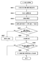
次にS240でCPU15は、撮影モードとして打上花火モードが設定されているか否か判定し、打上花火モードが設定されていると判定された場合はS220へ、打上花火モードが設定されていると判定されない場合はS202へ、それぞれ処理を進める。
Next, in S240, the
S202でCPU15は、撮影モードとして天体モードが設定されているか否か判定し、天体モードが設定されていると判定された場合はS250へ、天体モードが設定されていると判定されない場合はS230へ、それぞれ処理を進める。
In S202, the
S230でCPU15は、通常の撮影準備処理を行う。通常の撮影準備処理は、従来と同様の撮影準備処理であってよい。撮影準備処理においてCPU15は、上述したレリーズボタンの半押し操作(SW1オン)に応じてAE処理やAF処理を行い、S212でレリーズボタンの全押し操作(SW2オン)が検出されたかどうかを判定する。なお、SW1オンが検出されなければ、CPU15は処理をS212へ進める代わりにS201へ戻す。
In S230, the
一方、天体モードが設定されていると判定された場合、CPU15はS250において天体AFの実施を推奨するか否かの判定を行い、推奨すると判定した場合にはそれを報知するためのメッセージを表示装置10に表示し、処理をS203に進める。例えばCPU15は、現在から所定時間以内の過去に、現在の環境と同じ環境で天体AFが行われているか、同じ環境についての基準位置が更新されていれば、天体AFの実施を推奨せずに、処理をS212に進める。本実施形態では、天体AFに関する環境を、撮影光学系31の焦点距離、撮影光学系31の鏡筒の内部温度、デジタルカメラ1の仰角、の3つのパラメータの組み合わせで特定するものとするが、これは一例であり、例えば他のパラメータが含まれてもよい。なお、基準位置とは、過焦点距離、つまり無限遠が被写界深度に入る一番近い撮影距離に対応するフォーカスレンズ3の位置である。現在から所定時間以内の過去に現在と同じ環境で天体AFが行われていないか、現在と同じ環境についての基準位置が更新されていない場合、CPU15は天体AF実施を推奨する。
On the other hand, if it is determined that the celestial mode is set, the
S203でCPU15は、天体AF処理の開始指示が入力されたか否かを判定し、指示が入力されたと判定されればS204へ、入力されていないと判定されればS210へ処理を進める。この開始指示は例えば指示回路24に含まれるスイッチやボタンの操作であってよい。
In S203, the
S204でCPU15は、ある撮影画像についての、撮影条件(撮像素子5の蓄積時間(シャッタースピード)、撮像回路6の増幅率(撮影感度)、絞り4のF値)と、AE処理回路13の出力値とから、測光値を取得し、処理をS205へ進める。
In S <b> 204, the
S205でCPU15は、取得した測光値から、被写体が低照度か否かを判定し、低照度と判定されればS206へ、低照度でないと判定されればS220へ処理を進める。この判定は、予め定めた低照度判定用の閾値より測光値が低いか否かの判定であってよい。
In S205, the
S220でCPU15は、第2モータ駆動回路19を制御してフォーカスレンズ3を定点(特定の位置)に移動させる。ここでいう定点とは過焦点距離に対応するフォーカスレンズ3の位置であり、例えば撮影光学系31の焦点距離と対応付けて記憶装置25に予め登録されている。本明細書では、この定点を天体AFの基準位置とする。なお、後述するように、天体AFの基準位置は変更されうる。
In S220, the
S220が実行されるのは、打ち上げ花火モードの場合(S240,Y)と、天体モードで被写体が低照度でないと判定された場合(S205,N)である。
S205からS220に進んだ場合は、天体AFの実行に不適切な場合であるため、S220でCPU15は表示装置10へのメッセージ表示などにより天体AFの失敗をユーザに報知してもよい。また、被写体が明るすぎる(例えば月や地上の照明などが入っている)ことが失敗の原因であることを知らせてもよい。
なお、打上花火モードの場合(S240からS220に進んだ場合)は、このような報知を行う必要はない。フォーカスレンズ3を定点に移動させたら、CPU15は処理をS210に進める。
S220 is executed in the fireworks display mode (S240, Y) and in the celestial mode when it is determined that the subject does not have low illuminance (S205, N).
When the process proceeds from S205 to S220, it is inappropriate for the execution of the celestial AF, so the
In the fireworks display mode (when the process proceeds from S240 to S220), it is not necessary to perform such notification. When the
一方、被写体が低照度と判定された場合、CPU15はS206でスキャンAF時の撮影条件(絞り4のF値、撮像素子5の蓄積時間、撮像回路6の増幅率の組み合わせ)を決定する。CPU15は例えばS204で取得した測光値に対して適正露出となる撮影条件を基準として、所定段数分(例えば7段分)出力が低下する組み合わせのうち、所定の範囲内の組み合わせを決定する。
On the other hand, if it is determined that the subject has low illuminance, the
ここで、出力が適正露出時から所定段数分低下する組み合わせとするのは、低照度の被写体について、撮影画像に求められる適正な信号出力とスキャンAFにおける適正な信号出力とが異なるからである。
撮影画像においては1〜2等星の明るい星の像の信号が飽和しても問題にならず、むしろ3〜6等星といった暗い星が画像上で認識されるので、明るい星の像の信号が飽和する撮影条件の方が好ましい場合がある。これに対してスキャンAFにおいては、明るい星の像の信号が飽和した場合、AF処理回路14でのAF評価値作成の特性上、ピントが合った状態より、多少ピントがぼけた状態の時の方がAF評価値が大きくなり、正しい合焦位置を求めることができない。そのため、明るい星の像の信号が飽和しないよう、適正露出時よりも低い出力が得られる撮影条件(マイナス補正した撮影条件)としている。なお、適正露出に対応する撮影条件からどの程度の段数マイナス補正するかは、予め定めておくことができる。
Here, the reason why the output is reduced by a predetermined number of steps from the time of proper exposure is that an appropriate signal output required for a captured image is different from an appropriate signal output in scan AF for a low-illuminance subject.
In the photographed image, it does not matter if the signal of a bright star image of 1st to 2nd stars is saturated, but rather a dark star such as 3rd to 6th stars is recognized on the image. There may be a case where the photographing condition is saturated. On the other hand, in the scan AF, when the signal of the bright star image is saturated, the
図3は、本実施形態においてスキャンAF時の撮影条件を決定するために用いることのできるプログラム線図の例を示す。なお、このプログラム線図はあくまで一例であり、撮影光学系31の開放F値などの条件に応じて適切なプログラム線図が用いられる。
FIG. 3 shows an example of a program diagram that can be used to determine imaging conditions during scan AF in the present embodiment. This program diagram is merely an example, and an appropriate program diagram is used according to conditions such as the open F value of the photographing
プログラム線図における各パラメータの上限値と下限値は典型的な天体撮影シーンを想定して決定されてよい。図3のプログラム線図では上限値はF値がF2.8(Av=3)、蓄積時間が1秒(Tv=0)、増幅率がISO 100相当(Sv=5)であり、この値はAF枠内に多くの1等星・2等星・惑星が存在するシーンを想定して決定している。また、下限値はF値がF2.8(Av=3)、蓄積時間が4秒(Tv=−2)、増幅率がISO 800相当(Sv=8)である。この値はAF枠内に多くの1等星・2等星・惑星が存在しないかもしくは少なく、3〜6等星の数も多くないシーンを想定して決定している。なお、上限値や下限値は予め実験的に設定することができる。
The upper limit value and lower limit value of each parameter in the program diagram may be determined assuming a typical astronomical scene. In the program diagram of FIG. 3, the upper limit value is F value F2.8 (Av = 3), accumulation time is 1 second (Tv = 0), and amplification factor is equivalent to ISO 100 (Sv = 5). It is determined assuming a scene where there are many first-class stars, second-class stars, and planets in the AF frame. The lower limit value is F value F2.8 (Av = 3),
CPU15は、S204で取得した測光値(Ev)から所定段数分(ここでは7Ev)減じた値と図3のプログラム線図とから、F値、蓄積時間、増幅率の組み合わせを決定する。なお、Ev値がプログラム線図の範囲外の場合、CPU15はプログラム線図の上限値または下限値の組み合わせを撮影条件として決定する。
The
このようにしてスキャンAF時の撮影条件を決定すると、CPU15は処理をS207へ進め、撮像素子5の駆動モードと、表示装置10の表示をライブビュー表示用の状態から天体AF用の状態に変更する。具体的には、CPU15は撮像素子5の駆動モードを、加算読み出しモードから非加算読み出しモードに変更するとともに、表示装置10の表示内容を、ライブビュー画像から天体AF中であることを報知する表示に変更する。
After determining the shooting conditions during the scan AF in this way, the
本実施形態で天体AF時の撮像素子5の蓄積時間は1秒以上であり、表示装置10に表示する画像の更新周期も1秒以上となる。また、スキャンAFにおいては複数のスキャンポイントでの撮影が必要であるため、AFに要する時間が長くなる。このため、天体AFの実施中のカメラ1の動作をユーザが故障と誤認しないよう、天体AFの実行中であることをメッセージ表示などを通じてユーザに報知する。なお、メッセージに加え、天体AFに要する時間を計算して残り時間を表示したり、開始からの経過時間を表示したりすることもできる。
In this embodiment, the accumulation time of the
次にS208でCPU15は、スキャンAFを実行する。このスキャンAFの詳細について図4および図5を用いて説明する。
図4は、フォーカスレンズ3の位置と、AF評価値との関係を模式的に示した図である。天体AFにおけるスキャンAFは、上述した基準位置(定点)を中心に比較的狭いスキャン範囲を有し、スキャン範囲の開始点をA、終了点をB、探索する合焦位置をCで示している。
In step S208, the
FIG. 4 is a diagram schematically showing the relationship between the position of the
図5のフローチャートを用いて具体的な動作について説明する。
S501でCPU15は、撮影光学系31の現在の焦点距離に基づいて記憶装置25を参照し、天体AFの基準位置を取得する。
次いでCPU15は、スキャン間隔を決定する(S502)。スキャン間隔が狭いと合焦位置の探索精度は向上するが、スキャンポイントが多くなるためAFに要する時間が長くなるため、精度の許す範囲で広く設定する。例えば、開放F値における焦点深度の3〜5倍程度の値とすることができる。
A specific operation will be described with reference to the flowchart of FIG.
In S <b> 501, the
Next, the
次にCPU15は過去に天体AFを実行した際の撮影環境に関する情報と、現在の撮影環境に関する情報を取得する(S503)。ここでは、撮影環境に関する情報として、撮影光学系31の内部温度とデジタルカメラ1の姿勢(仰角)とを少なくとも用い、必要により撮影光学系31の焦点距離をさらに用いる。内部温度は温度センサ38から、焦点距離は第2モータ駆動回路19から、角度は触れ検出センサ35からそれぞれ取得できる。撮影環境に関する情報は、対応する基準位置とともに記憶装置25に保存されている。
Next, the
そして、CPU15は、基準位置の無限遠としての確からしさに基づいてスキャンポイント数を決定する(S504)。製品出荷時のように、天体AFが一度も実行されていない場合には、製造時に基準位置を測定した環境に関する情報と、撮影時(現在)の環境に関する情報とを用いる。なお、製造時における基準位置は、デジタルカメラを水平(仰角0度)にして測定される。
Then, the
例えば、デジタルカメラ1の仰角が30度±15度程度で内部温度が常温の場合を標準的な環境として、その際のスキャンポイント数を7点とする。また、仰角が水平に近い(例えば±15度程度未満)場合や、製造時における基準位置の測定時の内部温度と現在の内部温度がほぼ等しいと判定できる場合(例えば、差が2℃以内の場合)は、標準的な環境よりスキャンポイント数を減らす。一方、仰角が標準的な環境より大きい(天頂付近を撮影している)場合や、製造時における基準位置の測定時の内部温度と現在の内部温度とが大きく異なる場合(例えば、差が5℃以上の場合)は、スキャンポイント数を標準的な環境より増やす。スキャンポイント数の増減は、スキャン範囲の拡縮に相当する。
For example, assuming that the elevation angle of the
また、過去に天体AFが実行されている場合、CPU15は、過去に天体AFが実行された際の撮影環境(焦点距離、内部温度、仰角)と、現在の撮影環境とに基づいてスキャンステップ数を決定する。具体的には、CPU15は、例えば記憶装置25に保存されている、過去の天体AFの結果(合焦位置)もしくは更新された基準位置と、対応する撮影環境とを参照し、現在の撮影環境と同じか差の少ない撮影環境で得られた結果があるかどうかを調べる。
When the celestial AF has been executed in the past, the
天体AFの実行結果(合焦位置)のみが保存されている場合と、天体AFの結果を補間して更新された基準位置が含まれている場合がある。
そこでまずCPU15は、現在の環境とほぼ等しい撮影環境で実行された天体AFの結果が保存されていれば、その結果(合焦位置)を基準位置とする。
現在の環境とほぼ等しい撮影環境で実行された天体AFの結果がなければ、CPU15は、補間により更新された基準位置の中で、ほぼ等しいか差の小さい撮影環境に対応したものを採用する。
いずれにも該当しない場合、CPU15は天体AFが実行されていないものとして、製造時に基準位置を測定した環境に基づいてステップ数を決定する。
There may be a case where only the execution result (focus position) of the celestial AF is stored, and a case where the reference position updated by interpolating the result of the celestial AF is included.
Therefore, first, if the result of the celestial AF executed in the photographing environment substantially equal to the current environment is stored, the
If there is no result of astronomical AF executed in a shooting environment that is substantially equal to the current environment, the
If none of the above applies, the
なお、本実施形態では、撮影環境のうち焦点距離に関しては完全に合致する値を参照するものとし、内部温度、仰角の差に応じてスキャンポイント数を決定する。CPU15は、内部温度と仰角の両方がほぼ等しい場合はスキャンポイント数を5点、内部温度がほぼ等しく、仰角の差が小さい場合はスキャンポイント数を7点に決定する。また、内部温度がほぼ等しく、仰角の差が大きい場合は、CPU15は仰角の差に応じてスキャンポイント数を9点以上に決定する。
また、CPU15は、内部温度の差が小さく仰角がほぼ等しい場合はスキャンポイント数を7点、内部温度の差が小さく仰角がほぼ等しい範囲でない場合は仰角の差に応じてスキャンポイント数を9点以上に決定する。さらに、CPU15は、内部温度の差が大きい場合には、仰角の差に応じてのスキャンポイント数を9点以上に決定する。
In the present embodiment, a value that perfectly matches the focal length in the imaging environment is referred to, and the number of scan points is determined according to the difference in internal temperature and elevation angle. The
Further, the
ここでは、内部温度の差が5℃以下の場合に「ほぼ等しい」と判定し、5℃超〜10℃以下の場合に「差が小さい」と判定し、10℃超の場合に「差が大きい」と判定する。
また、仰角の差が10度以下であれば「ほぼ等しい」と判定し、10度超〜20度以下の場合に「差が小さい」と判定し、20度超の場合に「差が大きい」と判定する。
ただし、これらは一例であって、他の閾値を用いて判定してもよいし、分類の数を増やしたり減らしたりしてもよい。
Here, when the difference in internal temperature is 5 ° C. or less, it is determined as “substantially equal”, when it exceeds 5 ° C. to 10 ° C. or less, it is determined as “difference is small”. Is determined to be “large”.
Further, if the difference in elevation angle is 10 degrees or less, it is determined as “almost equal”, and if it is greater than 10 degrees to 20 degrees or less, it is determined as “difference is small”, and if it is greater than 20 degrees, “difference is large”. Is determined.
However, these are merely examples, and determination may be made using other threshold values, or the number of classifications may be increased or decreased.
同じ焦点距離について、内部温度と仰角の複数の組み合わせに対応した基準位置が記録されている場合、まず内部温度が最も近いものを探索し、次いで仰角の差を評価する。
このようにスキャンポイント数を決めるのは、天体AFの時間が長くなることを回避しつつ、確実に合焦位置を検出できるようにするためである。
When reference positions corresponding to a plurality of combinations of the internal temperature and the elevation angle are recorded for the same focal length, a search is first made for the closest internal temperature, and then the difference in elevation angle is evaluated.
The reason for determining the number of scan points in this way is to ensure that the in-focus position can be reliably detected while avoiding a long time for the celestial AF.
以上のようにスキャンポイント数を決定したら、CPU15は処理をS505に進めてスキャン動作を実行し、AF評価値を取得する。
すなわち、CPU15は第2モータ駆動回路19を介してフォーカス駆動モータ22を制御し、フォーカスレンズ3をスキャン開始位置(図4の位置A)に移動させる。そして、CPU15はスキャン開始位置からスキャン終了位置(図4の位置B)まで、スキャン間隔ずつフォーカスレンズ3を移動させて各位置で撮影を実行し、各位置で得られた画像について、AF処理回路14が出力するAF評価値を取得する。
When the number of scan points is determined as described above, the
That is, the
S506でCPU15は、スキャン動作によって得られたAF評価値の信頼性を公知の任意の方法によって評価し、信頼できると判定されれば処理をS507に進め、信頼できると判定されなければ処理をS510に進める。
In S506, the
S507でCPU15は、取得したAF評価値から、AF評価値が最大になるフォーカスレンズ3の位置(図4の位置C)を求める。
In S507, the
スキャン間隔ごとにフォーカスレンズ3の位置を変えるため、得られたAF評価値の最大値が真の最大値とは限らない。例えば、図4に示す例で、合焦位置近傍ではフォーカスレンズ3の位置a1,a2,a3でAF評価値が取得された場合、位置a2で取得されたAF評価値が最大値となるが、真の最大値は位置Cで得られる。したがって、CPU15は、取得されたAF評価値の最大値と、その前後に取得されたAF評価値、およびそれらが得られたフォーカスレンズ3の位置とから、AF評価値の真の最大値が得られる位置Cを求める。
Since the position of the
フォーカスレンズ3が位置a2のときに最大のAF評価値Y1が取得され、その前後の位置a1、a3でAF評価値Y2、Y3が取得されたとすると、フォーカスレンズ3の合焦位置Cは以下の式で求めることができる。

CPU15はフォーカスレンズ3の合焦位置を求めると、基準位置と比較し(S508)、合焦位置が基準位置から所定範囲内にあれば天体AFが成功した(天体AFの結果が信頼できる)と判定する。そして、CPU15は、検出された合焦位置(図4の位置C)へフォーカスレンズ3を駆動する(S509)。
When the
S508における所定範囲は例えば、基準位置と被写体(天体)の真の合焦位置との差を生じさせる各種の誤差(温度計の誤差、姿勢検出誤差、スキャンAFの誤差)や経時変化、同じ環境における合焦位置ずれの再現性などを考慮して予め定めることができる。また、前景に樹木や建物などの被写体が存在する場合の影響を考慮して、基準位置より近距離側の範囲を遠距離側の範囲より狭くする。 The predetermined range in S508 is, for example, various errors (thermometer error, posture detection error, scan AF error) that cause a difference between the reference position and the true in-focus position of the subject (celestial body), changes over time, and the same environment. It can be determined in advance in consideration of the reproducibility of the in-focus position shift at. Further, in consideration of the effect when a subject such as a tree or a building exists in the foreground, the range on the near side from the reference position is made narrower than the range on the far side.
例えば、
・温度計の誤差が2.5℃(合焦位置が開放F値の焦点深度の1.5倍相当)、
・姿勢検出誤差が5度(合焦位置が開放F値の焦点深度の2.5倍相当)
・スキャンAFの誤差が開放F値の焦点深度の0.5倍相当
・経時変化が開放F値の焦点深度の1.5倍相当
・同じ環境における合焦距離ずれの再現性が開放F値の焦点深度の1.5倍相当
であるとする。この場合、各数値の二乗平均平方根(RMS)を求め、所定の係数を考慮して、遠距離側の範囲は開放F値の焦点深度の6〜7倍相当とすることができる。近距離側の範囲は、被写体のぼけが目立たない範囲、例えば開放F値の焦点深度の3倍相当とすることができる。所定範囲は焦点距離に応じて定めることができる。
For example,
・ The error of the thermometer is 2.5 ° C. (the in-focus position is equivalent to 1.5 times the depth of focus of the open F value),
・ Attitude detection error is 5 degrees (the in-focus position is equivalent to 2.5 times the depth of focus of the open F value)
-Error in scan AF is equivalent to 0.5 times the depth of focus of the open F value-Time-dependent change is equivalent to 1.5 times the depth of focus of the open F value-Reproducibility of in-focus distance deviation in the same environment is the open F value It is assumed that it is equivalent to 1.5 times the depth of focus. In this case, the root mean square (RMS) of each numerical value is obtained, and the range on the far side can be equivalent to 6 to 7 times the depth of focus of the open F value in consideration of a predetermined coefficient. The range on the short distance side can be set to a range where the blur of the subject is not noticeable, for example, equivalent to three times the focal depth of the open F value. The predetermined range can be determined according to the focal length.
S506でAF評価値が信頼できると判定されなかった場合と、S508で合焦距離と基準位置との差が所定範囲内と判定されなかった場合、S510でCPU15は、S220と同様に、天体AFの基準位置(定点)にフォーカスレンズ3を駆動する。
以上が、天体AFモードでのスキャンAF動作である。
If it is determined in S506 that the AF evaluation value is not reliable, or if the difference between the in-focus distance and the reference position is not determined to be within the predetermined range in S508, the
The above is the scan AF operation in the celestial AF mode.
図2に戻り、S209でCPU15は撮像素子5の駆動モードをライブビュー表示用のモードに戻すとともに、表示装置10の表示もライブビュー画像の表示に戻す。さらにCPU15は、S208で行った天体AFの成否をユーザに報知する。例えば、天体AFが成功した場合、CPU15はLED29を点灯させ、表示装置10のライブビュー画像に緑の枠を重畳表示する。また、天体AFが失敗した場合、CPU15は表示素子29を点滅させ、表示装置10のライブビュー画像に黄色の枠を重畳表示する。
Returning to FIG. 2, in S <b> 209, the
そしてCPU15はS210において、SW1がオンしているか(レリーズボタンが半押し操作されたか)確認し、SW1がオンしていれば処理をS211に進めて天体AEを実行し、SW1がオンしていなければ処理をS201に戻す。
In S210, the
S211でCPU15は、S204で取得された測光値から、適性露出の画像を得るための撮影条件(絞り4のF値、撮像素子5の蓄積時間、撮像回路6の増幅率の組み合わせ)を決定する。AF時と異なり、記録する画像の撮影においては1〜2等星の明るい星の像の信号が飽和しても問題にならず、むしろ3〜6等星といった暗い星が画像上で認識される方が好ましいので、適性露出となるような撮影条件を決定する。
なお、S204で取得した測光値を用いずに、S211の実行時にAE処理回路13から測光値を取得して用いるようにしてもよい。
In S <b> 211, the
Instead of using the photometric value acquired in S204, the photometric value may be acquired from the
天体AEの実行後CPU15はS212において、SW2がオンしているか(レリーズボタンが全押し操作されたか)確認し、SW2がオンしていれば処理をS213に進め、記録用画像の生成(露光)処理および、記録用画像の記録処理を実行する。記録用画像の生成処理や、記録処理は公知であるため説明を省略する。SW2がオンになっていなければ、CPU15は処理をS201へ戻す。なお、S212の処理において用いられるフォーカスレンズ3の位置は、定点(S220)、天体AF(S208)の結果、通常AF(S230)の結果、もしくは現在から所定時間以内の過去に現在と同じ環境で行われた天体AFの結果である。
In post-execution CPU15 is S212 celestial AE, SW2 is that if (or release button is pressed fully) to confirm on, SW2 proceeds to
撮影・記録処理を行った後、CPU15はS214において、天体AFが実行されたか否かを判定し、実行されたと判定されればS215へ、実行されていない(通常AFが実行された)と判定されればS201へ、処理を進める。そして、S215では基準位置の更新処理を、S216ではピント補正量をそれぞれ更新する。なお、基準位置やピント補正量の更新は天体AFを伴う撮影・記録処理が実行されるたびに行わなくてもよい。
After performing the photographing / recording process, the
S215における基準位置の更新に関して、図6のフローチャートを用いて説明する。基準位置の更新処理においてCPU15は更新手段として機能する。
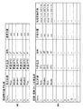
上述の通り、基準位置は製造時に一部の離散的な焦点距離について測定されているほか、他の焦点距離についての基準位置は測定された基準位置から補間計算により求められ、例えば記憶装置25に図7に示すように記録されている。
The update of the reference position in S215 will be described using the flowchart of FIG. In the reference position update process, the
As described above, the reference position is measured for some discrete focal lengths at the time of manufacture, and the reference positions for other focal lengths are obtained by interpolation calculation from the measured reference positions. It is recorded as shown in FIG.
製造時には、「製造時の基準位置」と記載された形式で基準位置が記録される。設定可能な焦点距離の一部または全部と、製造時の環境における内部温度と仰角との組み合わせについて測定された基準位置が記録される。ここでは内部温度20℃、仰角0度の環境で測定されているものとする。なお、図7では6つの焦点距離に関して測定されているが、これは一例であり、焦点距離の数は任意である。 At the time of manufacture, the reference position is recorded in a format described as “reference position at the time of manufacture”. A reference position measured for some or all of the settable focal lengths and a combination of internal temperature and elevation angle in the manufacturing environment is recorded. Here, it is assumed that the measurement is performed in an environment where the internal temperature is 20 ° C. and the elevation angle is 0 degree. In FIG. 7, measurement is performed with respect to six focal lengths, but this is an example, and the number of focal lengths is arbitrary.
S601とS602においてCPU15は、今回の天体AF実行時の撮影環境の情報(焦点距離、内部温度、仰角)と、今回の天体AFで検出された合焦距離を取得する。
In S <b> 601 and S <b> 602, the
S603においてCPU15は、記憶装置25の「記録・更新された合焦位置」(図7)が記録されている領域を参照し、今回の天体AFとほぼ等しい環境で過去に天体AFが実行されているか調べる。CPU15は、例えば基準位置を更新した過去の天体AFのうち、今回の天体AFと焦点距離が等しく、内部温度の差が5℃以下かつ仰角の差が10°以下のものを、ほぼ等しい環境で実行された天体AFと判定する。
In S603, the
該当する天体AFが実行されていた場合、CPU15はS604で、記憶装置25に記録されている、該当する天体AFに関する撮影環境および合焦距離を、今回の天体AFについての値を用いて更新する。更新は今回の値への置き換えであってもよいし、記録されていた値と今回の値とから得られる値(例えば平均値)への置き換えであってもよい。
If the corresponding celestial object AF has been executed, the
今回の天体AFとほぼ等しい環境で過去に天体AFが実行されていなければ、CPU15は処理をS605へ進め、「記録・更新された合焦位置」に今回の天体AFに関する値を追加する。
「記録・更新された合焦位置」の記録容量には制限があるため、上限値に達した場合は最も古い情報に上書きして記録する。削除し、その領域に新たな値を記録する。これは、古い情報は最新の情報より信頼性が低く、また使用される頻度も低いためである。
If the celestial AF has not been executed in the past in an environment substantially equal to the celestial AF of this time, the
Since the recording capacity of the “recorded / updated in-focus position” is limited, when the upper limit is reached, the oldest information is overwritten and recorded. Delete and record a new value in that area. This is because the old information is less reliable than the latest information and is less frequently used.
S606でCPU15は、基準位置を焦点距離に関して補間可能か否かを判定する。具体的にはCPU15は、内部温度と仰角がほぼ等しく、基準位置の補間に必要な複数の焦点距離(例えば、広角端、望遠端と、中間の焦点距離)で天体AFの結果(合焦位置)が取得されていれば、基準位置を焦点距離に関して補間可能と判定する。
In step S606, the
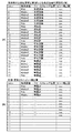
補間可能と判定された場合、CPU15はS607で補間を行い、基準位置のテーブルに追加する。図8のIndex1〜6は、内部温度20℃、仰角45度における基準位置を、焦点距離に関して補間した例を示している。補間方法に特に制限はないが、補間に用いる基準位置と焦点距離との組を二次元座標として例えば二次ラグランジェ補間多項式により二次関数を求め、補間する焦点距離に該当する二次関数の値を基準位置として求めることができる。
If it is determined that interpolation is possible, the
S608でCPU15は、基準位置を内部温度について補間可能か否かを判定する。具体的にはCPU15は、焦点距離と仰角が等しく、内部温度が異なる複数の更新された基準位置が存在すれば、基準位置を内部温度について補間可能と判定する。したがって、図8のように、仰角45度、内部温度20℃(Index1〜6)と、仰角45度、内部温度10℃(Index7〜12)について、更新された基準位置が存在すれば、CPU15は内部温度10〜20℃について補間可能と判定する。補間方法に制限はないが、例えば線形補間を用いることができる。したがって、内部温度10℃と20℃に対応する基準位置の平均値を内部温度15℃の基準位置として補間することができる(Index13〜18)。
In S608, the
S610でCPU15は、基準位置の仰角方向の補間が可能か判定する。具体的にはCPU15は、焦点距離と内部温度が等しく、仰角が異なる複数の更新された基準位置が存在すれば、基準位置を仰角について補間可能と判定する。したがって、図8のように、仰角45度、内部温度20℃(Index1〜6)と、仰角75度、内部温度20℃(Index19〜24)について、更新された基準位置が存在すれば、CPU15は仰角45〜75度について補間可能と判定する。補間方法に制限はないが、例えば線形補間を用いることができる。したがって、仰角45度と75度に対応する基準位置の平均値を仰角60度の基準位置として補間することができる(Index25〜30)。
このような処理により、CPU15は基準位置を更新する。
In S610, the
By such processing, the
次に、S215におけるピント補正値の更新処理について説明する。
上述の通り天体AFでは、水平方向にも垂直方向にも加算(または間引き)しない画像信号に基づいてAF評価値を算出している。一方、S230での通常撮影処理の中で行われるスキャンAF(以下、通常AFと呼ぶ)では、処理の高速化のために、水平および垂直方向で加算(または間引き)した画像信号からAF評価値を算出している。
Next, the update process of the focus correction value in S215 will be described.
As described above, the celestial AF calculates the AF evaluation value based on the image signal that is not added (or thinned out) in the horizontal direction or the vertical direction. On the other hand, in the scan AF (hereinafter referred to as normal AF) performed in the normal photographing process in S230, the AF evaluation value is calculated from the image signal added (or thinned out) in the horizontal and vertical directions in order to increase the processing speed. Is calculated.
なお、SW2のオンが検出されて実行される撮影処理(記録用の画像を撮影する処理)では、水平方向にも垂直方向にも画像信号を加算(または間引き)しない。 It should be noted that in the photographing processing (processing for photographing a recording image) that is executed when SW2 is detected to be turned on, image signals are not added (or thinned out) in the horizontal direction or the vertical direction.
このように、天体AFと記録に用いられる画像信号の空間周波数成分は等しいが、通常AFに用いられる画像信号の空間周波数成分は、天体AFと記録に用いられる画像信号の空間周波数成分より高周波成分が少なくなる。そのため、通常AFの実行時は、AF処理回路14において用いられるハイパスフィルター(HPF)が抽出する高周波成分の帯域を、天体AF実行時よりも低くしている。
As described above, the spatial frequency component of the image signal used for recording is the same as that of the celestial AF, but the spatial frequency component of the image signal used for normal AF is higher than the spatial frequency component of the image signal used for celestial AF and recording. Less. Therefore, when performing normal AF, the high-frequency component band extracted by the high-pass filter (HPF) used in the
そのため、通常AFでのAF評価値がピークとなるフォーカスレンズ3の位置が、記録される画像の解像度が最大となるフォーカスレンズ3の位置と異なる場合がある。そのため、通常AFを実行した場合には、AF評価値がピークとなるフォーカスレンズ3の位置(合焦位置)を補正する。
For this reason, the position of the
合焦位置の補正量(ピント補正量)は、例えば製造時に、F値、焦点距離、フォーカスレンズ位置の複数の組み合わせについて測定し、記憶装置25に図9(a)に示すようなテーブル形式で記録しておくことができる。これにより、撮影時にテーブルを参照し、撮影条件に該当するピント補正値を取得することができる。なお、図9(a)の例では、開放F値と、6つの焦点距離と、4つのフォーカスレンズ位置(の範囲)との組み合わせに関するピント補正量を記録しているが、組み合わせの数は単なる一例である。
The focus position correction amount (focus correction amount) is measured for a plurality of combinations of the F value, focal length, and focus lens position at the time of manufacture, for example, and stored in the
なお、撮影時の絞りが開放でない場合、例えばF8.0以上のF値ではピント補正量を零とし、開放F値とF8.0の間のF値については、線形補間などによって該当するピント補正量を求めることができる。 If the aperture is not fully open, for example, the F correction value is F8.0 or more, the focus correction amount is zero, and the F value between the open F value and F8.0 is corrected by linear interpolation or the like. The amount can be determined.
また、フォーカスレンズ位置は、フォーカスレンズ3の移動範囲を4分割し、撮影時のフォーカスレンズ3の位置がいずれかの分割範囲に含まれるようにしている。したがって、焦点距離が同じであれば、同じ分割範囲に含まれる複数のフォーカスレンズ位置に対して同じピント補正量が用いられる。
Further, the focus lens position is obtained by dividing the movement range of the
一方、ピント補正量は、経時変化、製造時の測定誤差、補間計算誤差などによって、最適値にならないことがある。そのため、本実施形態では、天体AFの結果を用いてピント補正量を更新し、更新したピント補正量を記録する。図8(b)は、天体AFの結果を用いて更新されたピント補正量のテーブルの一例を示している。 On the other hand, the focus correction amount may not be an optimal value due to changes over time, measurement errors during manufacturing, interpolation calculation errors, and the like. For this reason, in the present embodiment, the focus correction amount is updated using the result of the celestial AF, and the updated focus correction amount is recorded. FIG. 8B shows an example of a focus correction amount table updated using the results of the celestial AF.
ピント補正量の更新処理について、図10のフローチャートを用いて説明する。
S901とS902においてCPU15は、S208で天体AFを実行した際の撮影環境(少なくとも焦点距離およびF値)と、結果(フォーカスレンズ位置)とを取得する。なお、ここでは天体AFが成功している(フォーカスレンズ3の合焦位置が基準位置から所定範囲内にある)ものとする。
The update process of the focus correction amount will be described with reference to the flowchart of FIG.
In S901 and S902, the
S903でCPU15は、天体AFと同じ範囲およびスキャンポイントで通常AFを実施し、得られたAF評価値に基づいて通常AFにおけるフォーカスレンズ3の合焦位置を求める。上述の通り、通常AFでは加算された画像信号を用い、天体AFより低い周波数帯域における高周波成分に基づいてAF評価値を算出する。天体モードでは三脚を用いて撮影することが一般的であるため、ここで通常AFのために撮影される画像は、基本的に天体AFを実施して撮影したシーンと同じシーンを撮影した画像であり、天体AFと同じ被写体について合焦位置を検出することになる。
In S903, the
S904でCPU15は、天体AFの結果である合焦位置と、S903における通常AFの結果である合焦位置との差を、天体AFを実行した環境(焦点距離、F値、フォーカスレンズ位置(範囲))におけるピント補正量として求める。
In S904, the
そしてCPU15は、S905で過去にほぼ等しい撮影環境(焦点距離、F値、およびフォーカスレンズ位置(範囲))についてピント補正量の記録・更新が行われたか否かを調べる。これは例えば記憶装置25の、図9(b)に示した「記録・更新されたピント補正量」の記録領域を参照することで実行可能である。なお、ここでは絞り値を開放F値に換算したピント補正量を記録するものとするが、絞り値の換算を行わないピント補正量と絞り値とを記録するようにしてもよい。
In step S905, the
該当するピント補正量の記録・更新が実行されていた場合、CPU15はS906で、記憶装置25に記録されている、該当するピント補正量の情報を、S904で算出した補正量を用いて更新する。更新は今回の値への置き換えであってもよいし、記録されていた値と今回の値とから得られる値(例えば平均値)への置き換えであってもよい。
該当するピント補正量の記録・更新が実行されていない場合、CPU15は処理をS907へ進め、「記録・更新されたピント補正量」に、今回算出した補正量を追加する。
If recording / updating of the corresponding focus correction amount has been executed, the
If recording / updating of the corresponding focus correction amount has not been executed, the
S908でCPU15は、ピント補正量を焦点距離に関して補間可能か否かを判定する。CPU15は、例えば絞り値とフォーカスレンズ位置(範囲)が等しく、ピント補正量の補間に必要な複数の焦点距離(例えば、広角端、望遠端と、中間の焦点距離)で天体AFの結果が取得されていれば、ピント補正量を焦点距離に関して補間可能と判定する。
In S908, the
補間可能な場合はS908にてピント補正量の焦点距離に関しての補間を行い、図8Index1〜6に示すようなそのフォーカスレンズ位置におけるピント補正量のテーブルを作成する。 If interpolation is possible, interpolation is performed on the focal length of the focus correction amount in S908, and a table of focus correction amounts at the focus lens positions as shown in FIGS.
補間可能と判定された場合、CPU15はS909で補間を行い、ピント補正量のテーブルに追加する。図9のIndex4は、Index1〜3を用い、開放F値、フォーカスレンズ位置(範囲)無限遠におけるピント補正量を、焦点距離Middle1に関して補間した例を示している。補間方法に特に制限はないが、補間に用いるピント補正量と焦点距離との組を二次元座標として例えば二次ラグランジェ補間多項式により二次関数を求め、補間する焦点距離に該当する二次関数の値をピント補正量として求めることができる。
If it is determined that interpolation is possible, the
このように、本実施形態の自動焦点調節装置は、無限遠の位置にある低照度の被写体を対象とした動作モードを有する。そして、撮像画像から得られるAF評価値に基づいて検出されたフォーカスレンズの合焦位置が、予め記憶された、過焦点距離に対応するフォーカスレンズの位置から所定範囲内にあるか否かに基づいて、検出された合焦位置が信頼性を有するか否かを判定する。そのため、自動焦点調節の結果、実際に無限遠に位置する被写体に適した合焦距離となっていることを確認することができる。 As described above, the automatic focus adjustment apparatus of the present embodiment has an operation mode for a low-illuminance subject at a position at infinity. Then, based on whether or not the focus position of the focus lens detected based on the AF evaluation value obtained from the captured image is within a predetermined range from the position of the focus lens corresponding to the hyperfocal distance stored in advance. Then, it is determined whether or not the detected in-focus position has reliability. Therefore, as a result of the automatic focus adjustment, it can be confirmed that the in-focus distance is suitable for a subject actually located at infinity.
さらに、検出された合焦位置が信頼性を有すると判定されなかった場合には、予め記憶された過焦点距離に対応する位置(基準位置)にフォーカスレンズを移動させるようにすれば、無限遠に位置する被写体に撮影光学系を確実に合焦させることが可能になる。 Furthermore, if the detected focus position is not determined to be reliable, the focus lens can be moved to a position (reference position) corresponding to the pre-stored hyperfocal distance to achieve infinity. Thus, it is possible to reliably focus the photographing optical system on the subject located at.
さらに、検出された合焦位置の信頼性を判定するための所定範囲を、基準位置から遠距離側の範囲と近距離側の範囲とから構成するとともに、近距離側の範囲が遠距離側の範囲より狭くなるように設定することができる。この場合、前景に合焦した状態を信頼性のある自動焦点調節結果と誤判定することを抑制できる。 Further, the predetermined range for determining the reliability of the detected in-focus position is composed of a range on the far side and a range on the near side from the reference position, and the range on the near side is on the far side. It can be set to be narrower than the range. In this case, it is possible to suppress erroneous determination of a state in focus on the foreground as a reliable automatic focus adjustment result.
また、過焦点距離に対応するフォーカスレンズの位置(基準位置)は、撮像装置の姿勢、撮影光学系の内部温度、経時変化などによって変化する。そのため、製造時に測定された基準位置を、実際に検出された合焦位置に基づいて更新あるいは修正するようにすれば、基準位置の精度を向上させることができ、結果として自動焦点調節の信頼性の判定精度を向上させることができる。 In addition, the position (reference position) of the focus lens corresponding to the hyperfocal distance varies depending on the attitude of the imaging apparatus, the internal temperature of the imaging optical system, changes with time, and the like. Therefore, if the reference position measured at the time of manufacture is updated or corrected based on the actually detected in-focus position, the accuracy of the reference position can be improved, and as a result, the reliability of automatic focusing is improved. The determination accuracy can be improved.
さらに、記録する画像信号とAF評価値を生成する画像信号とで空間周波数成分が異なる場合に用いる、合焦位置の補正量を、無限遠の位置にある低照度の被写体を対象とした動作モードで検出された合焦位置に基づいて修正することができる。それにより、補正量を測定した時点からの経時変化や測定時の計算誤差の影響を低減して合焦位置の精度を向上させることができる。そのため、一般的な被写体を対象とした動作モードでAF動作の高速化のために加算または間引きした画像信号を用いてAF評価値を生成する場合に、焦点検出精度を高めることができる。 Furthermore, the focus mode correction amount used when the spatial frequency component differs between the image signal to be recorded and the image signal to generate the AF evaluation value is an operation mode for a low-illuminance subject at an infinite position. The correction can be made based on the in-focus position detected in (1). Accordingly, it is possible to improve the accuracy of the in-focus position by reducing the influence of the change over time from the time when the correction amount is measured and the influence of the calculation error at the time of measurement. Therefore, the focus detection accuracy can be improved when the AF evaluation value is generated using the image signal added or thinned out in order to increase the speed of the AF operation in the operation mode for a general subject.
●(第2実施形態)
次に本発明の第2実施形態について説明する。本実施形態では、製造時に測定され記録された基準位置から、撮影時に用いる基準位置を計算で算出する。S208のスキャンAF処理とS215の基準位置更新処理以外は第1実施形態と共通でよいため、以下ではスキャンAF処理と基準位置更新処理について説明する。
● (Second Embodiment)
Next, a second embodiment of the present invention will be described. In the present embodiment, a reference position used at the time of photographing is calculated from a reference position measured and recorded at the time of manufacture. Except for the scan AF process in S208 and the reference position update process in S215, the process may be the same as in the first embodiment, and therefore, the scan AF process and the reference position update process will be described below.
図5のフローチャートを用いて、本実施形態におけるスキャンAF処理について説明する。S501,S502の処理は第1実施形態と共通である。
S503において、CPU15は基準位置を計測した際の撮影環境に関する情報(例えば図7の例では内部温度=20℃、仰角=0度)と、現在の撮影環境に関する情報を取得する。
The scan AF process in the present embodiment will be described using the flowchart of FIG. The processes in S501 and S502 are the same as those in the first embodiment.
In S <b> 503, the
そしてCPU15は、製造時に測定、記録された基準位置と、製造時と撮影時の環境の差に応じた換算係数とから、以下の式に従って撮影時の基準位置で算出する。
基準位置=
製造時の基準位置+内部温度の換算係数×(撮影時の内部温度−製造時の内部温度)+仰角の換算係数×(撮影時の仰角−製造時の仰角)
ただし、仰角は正の値とし、負の値の場合は0度とする。内部温度も上限(例えば40℃)と下限(0℃)を設け、上限を超える場合は上限値に、下限を下回る場合は下限値にする。
Then, the
Reference position =
Reference position at the time of manufacture + conversion factor of internal temperature x (internal temperature at the time of photographing-internal temperature at the time of manufacture) + conversion factor of the elevation angle x (elevation angle at the time of photographing-elevation angle at the time of manufacture)
However, the elevation angle is a positive value, and in the case of a negative value, it is 0 degree. The internal temperature is also provided with an upper limit (for example, 40 ° C.) and a lower limit (0 ° C.). When the upper limit is exceeded, the upper limit is set, and when the lower limit is reached, the lower limit is set.
内部温度および仰角に関する換算係数は複数の焦点距離のそれぞれについて、予め例えば実験的に定めた値を製造時に記憶装置25に記録しておく。また、換算係数は例えば天体AFが行われるたびに更新されてよい。
For the conversion factor relating to the internal temperature and the elevation angle, for example, values determined experimentally in advance for each of a plurality of focal lengths are recorded in the
また、天体AFが実行されている場合、CPU15は図7(b)に示した形式で記録されている天体AF実行時の環境と合焦位置とを用いて内部温度の換算係数と仰角の換算係数とを算出する。
例えば、ある焦点距離について、仰角が同じで、内部温度が(下限値から上限値の範囲で)異なる環境で天体AFが行われた場合、その焦点距離における内部温度の換算係数を算出し、追加または更新する。
同様に、ある焦点距離について、内部温度が同じで、仰角が(下限値から上限値の範囲で)異なる環境で天体AFが行われた場合、その焦点距離における仰角の換算係数を算出し、追加または更新する。
内部温度の変換係数と仰角の換算係数の算出と追加あるいは更新は、条件を満たす天体AFが行われるごとに実行されてよい。
When the celestial AF is executed, the
For example, if celestial AF is performed in an environment where the elevation angle is the same and the internal temperature is different (within the range from the lower limit value to the upper limit value) for a certain focal length, a conversion factor for the internal temperature at that focal length is calculated and added. Or update.
Similarly, when celestial AF is performed in an environment where the internal temperature is the same and the elevation angle is different (within the range from the lower limit value to the upper limit value), a conversion factor for the elevation angle at that focal length is calculated and added. Or update.
The calculation, addition, or update of the internal temperature conversion coefficient and the elevation angle conversion coefficient may be performed each time the celestial AF satisfying the condition is performed.
そして、CPU15は、換算係数の信頼性、具体的には更新の度合いに基づいてスキャンポイント数を決定する(S504)。CPU15は、天体AFがまだ行われていない場合、初期値としてCPU15は例えばスキャンポイント数を9点とする。一方の換算係数だけが更新されている場合、CPU15は初期値からスキャンポイント数を−1して8点とする。
また、内部温度と仰角の両方について換算係数が更新されている場合、CPU15は初期値からスキャンポイント数を−2して7点とする。
また、内部温度と仰角の両方について換算係数が更新されており、かつ、一方の換算係数が複数回更新されている場合、CPU15は初期値からスキャンポイント数を−3して6点とする。
内部温度と仰角の両方について換算係数が複数回更新されている場合、CPU15は初期値からスキャンポイント数を−4して5点とする。
スキャンポイント数の決定後、S505以降は第1実施形態と同様の処理を行う。
Then, the
When the conversion coefficient is updated for both the internal temperature and the elevation angle, the
When the conversion coefficient is updated for both the internal temperature and the elevation angle, and one conversion coefficient is updated a plurality of times, the
When the conversion coefficient is updated a plurality of times for both the internal temperature and the elevation angle, the
After the determination of the number of scan points, the same processing as in the first embodiment is performed after S505.
また、S215における基準位置の更新は以下のように行う。
天体AFで検出された合焦位置を次回の同一環境における天体AFで用いる基準位置とするように更新するとともに、合焦位置と基準位置との遠近関係に応じてS508で合焦位置の信頼性判定に用いる所定範囲の近距離側と遠距離側の範囲の大きさを変更する。
The reference position is updated in S215 as follows.
The focus position detected by the celestial AF is updated to be the reference position used in the next celestial AF in the same environment, and the reliability of the focus position is determined in S508 according to the perspective relationship between the focus position and the reference position. The size of the range on the near side and the far side of the predetermined range used for the determination is changed.
具体的には、合焦位置が基準位置より遠距離側であった場合、CPU15は所定範囲の近距離側の範囲を狭くする。合焦位置が基準位置より遠距離側であることは製造時の測定結果が近距離側にずれていることを意味しており、近距離側の物体などに誤って合焦する可能性が高まっていることを示す。そのため、所定範囲のうち、近距離側の範囲をさらに狭めることで、近距離側の物体など誤って合焦することを抑制できる。CPU15は、近距離側の範囲を、例えば開放F値の焦点深度の2倍相当とすることができる。
Specifically, when the in-focus position is on the far side from the reference position, the
逆に、合焦位置が基準位置より近距離側であった場合、CPU15は所定範囲の遠距離側の範囲を狭くする。合焦位置が基準位置より近距離側であることは、製造時の測定結果が遠距離側にずれていることを意味しており、この場合、近距離側の物体などに誤って合焦する可能性は低いと考えられため、近距離側の範囲を変更する必要はない。一方、遠距離側の範囲については狭くすることで、ノイズなどの影響で偽合焦することを抑制できる。CPU15は、遠距離側の範囲を、例えば開放F値の焦点深度の4〜5倍相当とすることができる。
Conversely, if the in-focus position is closer to the reference position than the reference position, the
さらに、CPU15は、内部温度の換算係数と、仰角の換算係数とを補間によって更新することができる。更新する変換係数は、既に行われた天体AFが行われた内部温度もしくは仰角に対する換算係数から、例えば最小二乗法を用いて直線補間を行って求めることができる。
本実施形態によっても、第1実施形態と同様の効果を実現することができる。
Further, the
According to the present embodiment, the same effect as that of the first embodiment can be realized.
(その他の実施形態)
上述の実施形態では、ピント補正量はフォーカスレンズ位置(範囲)と焦点距離との組み合わせに対応した値であったが、さらに内部温度を組み合わせに含めてもよい。
(Other embodiments)
In the above-described embodiment, the focus correction amount is a value corresponding to the combination of the focus lens position (range) and the focal length, but the internal temperature may be further included in the combination.
また、本発明は、上述の実施形態の1以上の機能を実現するプログラムを、ネットワーク又は記憶媒体を介してシステム又は装置に供給し、そのシステム又は装置のコンピュータにおける1つ以上のプロセッサーがプログラムを読出し実行する処理でも実現可能である。また、1以上の機能を実現する回路(例えば、ASIC)によっても実現可能である。 Further, the present invention supplies a program that realizes one or more functions of the above-described embodiment to a system or apparatus via a network or a storage medium, and one or more processors in a computer of the system or apparatus execute the program. It can also be realized by a process of reading and executing. It can also be realized by a circuit (for example, ASIC) that realizes one or more functions.
3…フォーカスレンズ、4…絞り、5…撮像素子、8…メモリ、10…表示装置、11…コーデック、15…CPU、17…ドライバ回路、24…指示回路、25…記憶装置、35…振れ検出センサ、37…動きベクトル検出回路、38…温度センサ
DESCRIPTION OF
Claims (15)
前記AF評価値に基づいてフォーカスレンズの合焦位置を検出する検出手段と、
前記検出された合焦位置が、無限遠の位置にある被写体に対応する予め定められた基準位置から所定範囲内にある場合に、前記検出された合焦位置に前記フォーカスレンズを移動させ、前記検出された合焦位置が、前記所定範囲内にない場合に、所定位置に前記フォーカスレンズを移動させる制御手段と、
を有し、
前記所定位置は、前記基準位置または、前記検出手段が過去に検出した合焦位置のうち前記基準位置から前記所定範囲内にある合焦位置であることを特徴とする自動焦点調節装置。 Generating means for generating an AF evaluation value from an image signal;
Detecting means for detecting a focus position of the focus lens based on the AF evaluation value;
When the detected focus position is within a predetermined range from a predetermined reference position corresponding to an object at infinity, the focus lens is moved to the detected focus position, Control means for moving the focus lens to a predetermined position when the detected focus position is not within the predetermined range;
Have
Wherein the predetermined position, the reference position or the detection means autofocus system, characterized in that is in-focus position is within the predetermined range from the reference position of the focus position detected in the past.
前記撮像素子から画像信号を生成する手段と、
前記画像信号を用いる請求項1から12のいずれか1項に記載の自動焦点調節装置と、
を有することを特徴とする撮像装置。 An image sensor;
It means for generating the image pickup element or al picture image signal,
The automatic focusing apparatus according to any one of claims 1 to 12 , wherein the image signal is used .
An imaging device comprising:
前記AF評価値に基づいてフォーカスレンズの合焦位置を検出する工程と、
前記検出された合焦位置が、無限遠の位置にある被写体に対応する予め定められた基準位置から所定範囲内にある場合に、前記検出された合焦位置に前記フォーカスレンズを移動させる工程と、
前記検出された合焦位置が、前記基準位置から前記所定範囲内にない場合に、所定位置に前記フォーカスレンズを移動させる工程と、を有し、
前記所定位置は、前記基準位置または、過去に検出した合焦位置のうち前記基準位置から前記所定範囲内にある合焦位置であることを特徴とする自動焦点調節装置の制御方法。 Generating an AF evaluation value from the image signal;
Detecting a focus position of a focus lens based on the AF evaluation value;
Moving the focus lens to the detected focus position when the detected focus position is within a predetermined range from a predetermined reference position corresponding to a subject at infinity; and ,
Moving the focus lens to a predetermined position when the detected in-focus position is not within the predetermined range from the reference position;
The predetermined position, the control method of the automatic focusing device, wherein the reference position or a focus position within the predetermined range from the reference position of the focus position detected in the past.
Priority Applications (2)
| Application Number | Priority Date | Filing Date | Title |
|---|---|---|---|
| JP2015201542A JP6568448B2 (en) | 2015-10-09 | 2015-10-09 | Automatic focusing apparatus, control method therefor, and imaging apparatus |
| US15/288,158 US9832364B2 (en) | 2015-10-09 | 2016-10-07 | Automatic focal adjustment apparatus and method of controlling automatic focal adjustment apparatus, and image capture apparatus |
Applications Claiming Priority (1)
| Application Number | Priority Date | Filing Date | Title |
|---|---|---|---|
| JP2015201542A JP6568448B2 (en) | 2015-10-09 | 2015-10-09 | Automatic focusing apparatus, control method therefor, and imaging apparatus |
Publications (3)
| Publication Number | Publication Date |
|---|---|
| JP2017072809A JP2017072809A (en) | 2017-04-13 |
| JP2017072809A5 JP2017072809A5 (en) | 2018-11-08 |
| JP6568448B2 true JP6568448B2 (en) | 2019-08-28 |
Family
ID=58500260
Family Applications (1)
| Application Number | Title | Priority Date | Filing Date |
|---|---|---|---|
| JP2015201542A Active JP6568448B2 (en) | 2015-10-09 | 2015-10-09 | Automatic focusing apparatus, control method therefor, and imaging apparatus |
Country Status (2)
| Country | Link |
|---|---|
| US (1) | US9832364B2 (en) |
| JP (1) | JP6568448B2 (en) |
Families Citing this family (1)
| Publication number | Priority date | Publication date | Assignee | Title |
|---|---|---|---|---|
| CN106447728A (en) * | 2016-08-29 | 2017-02-22 | 华为技术有限公司 | Scanning state adjustment method and apparatus |
Family Cites Families (5)
| Publication number | Priority date | Publication date | Assignee | Title |
|---|---|---|---|---|
| JP4708737B2 (en) * | 2004-06-04 | 2011-06-22 | キヤノン株式会社 | Lens device |
| JP5134116B2 (en) | 2011-07-13 | 2013-01-30 | 富士フイルム株式会社 | Imaging apparatus and in-focus position search method |
| JP2014021373A (en) | 2012-07-20 | 2014-02-03 | Nikon Corp | Imaging device, storage device, and imaging program |
| JP6478534B2 (en) * | 2014-09-09 | 2019-03-06 | キヤノン株式会社 | Focus control device, imaging device, interchangeable lens, focus control method, and focus control program |
| JP2016061797A (en) * | 2014-09-12 | 2016-04-25 | キヤノン株式会社 | Focus adjustment device and control method therefor |
-
2015
- 2015-10-09 JP JP2015201542A patent/JP6568448B2/en active Active
-
2016
- 2016-10-07 US US15/288,158 patent/US9832364B2/en active Active
Also Published As
| Publication number | Publication date |
|---|---|
| US9832364B2 (en) | 2017-11-28 |
| US20170104919A1 (en) | 2017-04-13 |
| JP2017072809A (en) | 2017-04-13 |
Similar Documents
| Publication | Publication Date | Title |
|---|---|---|
| KR101847392B1 (en) | Image processing apparatus and method for controlling the same | |
| US11223774B2 (en) | Imaging apparatus, lens apparatus, and method for controlling the same | |
| JP6518452B2 (en) | Imaging apparatus and imaging method | |
| JP5115210B2 (en) | Imaging device | |
| JP6154081B2 (en) | Imaging device, imaging device body, and lens barrel | |
| US10477101B2 (en) | Focus detection apparatus, control method and storage medium | |
| JP5499853B2 (en) | Electronic camera | |
| WO2013094552A1 (en) | Imaging device, method for controlling same, and program | |
| JP5196768B2 (en) | Imaging device | |
| WO2013094551A1 (en) | Imaging device, method for controlling same, and program | |
| JP2018137613A (en) | Image processing apparatus, imaging apparatus and control method for image processing apparatus | |
| JP2009175442A (en) | Imaging apparatus | |
| JP6220144B2 (en) | Focus adjustment apparatus and control method thereof | |
| JP6568448B2 (en) | Automatic focusing apparatus, control method therefor, and imaging apparatus | |
| JPWO2019181024A1 (en) | Imaging device, imaging method, and program | |
| JP6257186B2 (en) | Imaging apparatus, imaging method, and program | |
| JP6645711B2 (en) | Image processing apparatus, image processing method, and program | |
| JP5446660B2 (en) | Image recognition apparatus and imaging apparatus | |
| JP2017194553A (en) | Image tremor correction device, control method of the same, imaging device, and program | |
| JP2009198975A (en) | Focus adjustment device and focus adjustment method therefor | |
| JP2017072809A5 (en) | ||
| JP2019148668A (en) | Focus adjustment device, and focus adjustment device control method | |
| US10681274B2 (en) | Imaging apparatus and control method thereof | |
| JP2018098764A (en) | Imaging apparatus and image synthesis method | |
| US20220292692A1 (en) | Image processing apparatus and method of processing image |
Legal Events
| Date | Code | Title | Description |
|---|---|---|---|
| A521 | Request for written amendment filed |
Free format text: JAPANESE INTERMEDIATE CODE: A523 Effective date: 20180904 |
|
| A621 | Written request for application examination |
Free format text: JAPANESE INTERMEDIATE CODE: A621 Effective date: 20180904 |
|
| A521 | Request for written amendment filed |
Free format text: JAPANESE INTERMEDIATE CODE: A523 Effective date: 20180911 |
|
| A977 | Report on retrieval |
Free format text: JAPANESE INTERMEDIATE CODE: A971007 Effective date: 20190320 |
|
| A131 | Notification of reasons for refusal |
Free format text: JAPANESE INTERMEDIATE CODE: A131 Effective date: 20190408 |
|
| A521 | Request for written amendment filed |
Free format text: JAPANESE INTERMEDIATE CODE: A523 Effective date: 20190605 |
|
| TRDD | Decision of grant or rejection written | ||
| A01 | Written decision to grant a patent or to grant a registration (utility model) |
Free format text: JAPANESE INTERMEDIATE CODE: A01 Effective date: 20190705 |
|
| A61 | First payment of annual fees (during grant procedure) |
Free format text: JAPANESE INTERMEDIATE CODE: A61 Effective date: 20190802 |
|
| R151 | Written notification of patent or utility model registration |
Ref document number: 6568448 Country of ref document: JP Free format text: JAPANESE INTERMEDIATE CODE: R151 |