JP6567048B2 - Sputtering target - Google Patents
Sputtering target Download PDFInfo
- Publication number
- JP6567048B2 JP6567048B2 JP2017519788A JP2017519788A JP6567048B2 JP 6567048 B2 JP6567048 B2 JP 6567048B2 JP 2017519788 A JP2017519788 A JP 2017519788A JP 2017519788 A JP2017519788 A JP 2017519788A JP 6567048 B2 JP6567048 B2 JP 6567048B2
- Authority
- JP
- Japan
- Prior art keywords
- target
- plate
- sputtering
- target plate
- backing plate
- Prior art date
- Legal status (The legal status is an assumption and is not a legal conclusion. Google has not performed a legal analysis and makes no representation as to the accuracy of the status listed.)
- Active
Links
- 238000005477 sputtering target Methods 0.000 title claims description 73
- 239000000463 material Substances 0.000 claims description 87
- 238000004544 sputter deposition Methods 0.000 claims description 44
- 238000005219 brazing Methods 0.000 claims description 39
- 238000000034 method Methods 0.000 claims description 39
- 238000001816 cooling Methods 0.000 claims description 15
- 239000000126 substance Substances 0.000 claims description 12
- 230000008018 melting Effects 0.000 claims description 11
- 238000002844 melting Methods 0.000 claims description 11
- 238000004519 manufacturing process Methods 0.000 claims description 10
- 238000002360 preparation method Methods 0.000 claims description 4
- 239000000758 substrate Substances 0.000 claims description 4
- 229910010293 ceramic material Inorganic materials 0.000 claims description 3
- 238000000168 high power impulse magnetron sputter deposition Methods 0.000 claims description 3
- 238000005422 blasting Methods 0.000 claims description 2
- 239000011248 coating agent Substances 0.000 claims description 2
- 238000000576 coating method Methods 0.000 claims description 2
- 239000002245 particle Substances 0.000 claims description 2
- 239000012634 fragment Substances 0.000 claims 1
- 239000000919 ceramic Substances 0.000 description 9
- 229910052750 molybdenum Inorganic materials 0.000 description 9
- ZOKXTWBITQBERF-UHFFFAOYSA-N Molybdenum Chemical compound [Mo] ZOKXTWBITQBERF-UHFFFAOYSA-N 0.000 description 8
- 239000010408 film Substances 0.000 description 8
- 239000011733 molybdenum Substances 0.000 description 8
- 238000005240 physical vapour deposition Methods 0.000 description 8
- 238000000151 deposition Methods 0.000 description 7
- 229910052738 indium Inorganic materials 0.000 description 7
- 239000002131 composite material Substances 0.000 description 6
- 230000008021 deposition Effects 0.000 description 6
- 239000000498 cooling water Substances 0.000 description 5
- 239000000853 adhesive Substances 0.000 description 4
- 230000001070 adhesive effect Effects 0.000 description 4
- APFVFJFRJDLVQX-UHFFFAOYSA-N indium atom Chemical compound [In] APFVFJFRJDLVQX-UHFFFAOYSA-N 0.000 description 4
- 238000005304 joining Methods 0.000 description 4
- RYGMFSIKBFXOCR-UHFFFAOYSA-N Copper Chemical compound [Cu] RYGMFSIKBFXOCR-UHFFFAOYSA-N 0.000 description 3
- 238000005452 bending Methods 0.000 description 3
- 229910052802 copper Inorganic materials 0.000 description 3
- 239000010949 copper Substances 0.000 description 3
- 150000004767 nitrides Chemical class 0.000 description 3
- 229910052721 tungsten Inorganic materials 0.000 description 3
- 238000009736 wetting Methods 0.000 description 3
- ATJFFYVFTNAWJD-UHFFFAOYSA-N Tin Chemical compound [Sn] ATJFFYVFTNAWJD-UHFFFAOYSA-N 0.000 description 2
- 229910052804 chromium Inorganic materials 0.000 description 2
- 238000009826 distribution Methods 0.000 description 2
- 239000011888 foil Substances 0.000 description 2
- 230000007246 mechanism Effects 0.000 description 2
- 150000001247 metal acetylides Chemical class 0.000 description 2
- 238000005488 sandblasting Methods 0.000 description 2
- 229910021332 silicide Inorganic materials 0.000 description 2
- 239000013077 target material Substances 0.000 description 2
- 230000000930 thermomechanical effect Effects 0.000 description 2
- 239000010409 thin film Substances 0.000 description 2
- WFKWXMTUELFFGS-UHFFFAOYSA-N tungsten Chemical compound [W] WFKWXMTUELFFGS-UHFFFAOYSA-N 0.000 description 2
- 239000010937 tungsten Substances 0.000 description 2
- 229910017750 AgSn Inorganic materials 0.000 description 1
- OKTJSMMVPCPJKN-UHFFFAOYSA-N Carbon Chemical compound [C] OKTJSMMVPCPJKN-UHFFFAOYSA-N 0.000 description 1
- 229910019974 CrSi Inorganic materials 0.000 description 1
- 229910001182 Mo alloy Inorganic materials 0.000 description 1
- 229910008484 TiSi Inorganic materials 0.000 description 1
- 229910001080 W alloy Inorganic materials 0.000 description 1
- QCEUXSAXTBNJGO-UHFFFAOYSA-N [Ag].[Sn] Chemical compound [Ag].[Sn] QCEUXSAXTBNJGO-UHFFFAOYSA-N 0.000 description 1
- 238000000889 atomisation Methods 0.000 description 1
- 230000015572 biosynthetic process Effects 0.000 description 1
- 239000003795 chemical substances by application Substances 0.000 description 1
- 238000004140 cleaning Methods 0.000 description 1
- 229910052593 corundum Inorganic materials 0.000 description 1
- 239000010431 corundum Substances 0.000 description 1
- 125000004122 cyclic group Chemical group 0.000 description 1
- 238000010586 diagram Methods 0.000 description 1
- 230000000694 effects Effects 0.000 description 1
- 238000010891 electric arc Methods 0.000 description 1
- 230000008020 evaporation Effects 0.000 description 1
- 238000001704 evaporation Methods 0.000 description 1
- 229910002804 graphite Inorganic materials 0.000 description 1
- 239000010439 graphite Substances 0.000 description 1
- 238000000227 grinding Methods 0.000 description 1
- 238000010438 heat treatment Methods 0.000 description 1
- 238000002513 implantation Methods 0.000 description 1
- 238000003754 machining Methods 0.000 description 1
- 238000001755 magnetron sputter deposition Methods 0.000 description 1
- 239000000155 melt Substances 0.000 description 1
- 239000012528 membrane Substances 0.000 description 1
- 229910052751 metal Inorganic materials 0.000 description 1
- 239000002184 metal Substances 0.000 description 1
- 239000007769 metal material Substances 0.000 description 1
- 150000002739 metals Chemical class 0.000 description 1
- 239000000203 mixture Substances 0.000 description 1
- 230000004792 oxidative damage Effects 0.000 description 1
- 230000035515 penetration Effects 0.000 description 1
- 238000000926 separation method Methods 0.000 description 1
- 230000035939 shock Effects 0.000 description 1
- FVBUAEGBCNSCDD-UHFFFAOYSA-N silicide(4-) Chemical compound [Si-4] FVBUAEGBCNSCDD-UHFFFAOYSA-N 0.000 description 1
- 229910052709 silver Inorganic materials 0.000 description 1
- 239000004332 silver Substances 0.000 description 1
- 230000003319 supportive effect Effects 0.000 description 1
- 230000003685 thermal hair damage Effects 0.000 description 1
- 229910052719 titanium Inorganic materials 0.000 description 1
- 238000001771 vacuum deposition Methods 0.000 description 1
- 229910052720 vanadium Inorganic materials 0.000 description 1
- 238000005019 vapor deposition process Methods 0.000 description 1
- 238000009763 wire-cut EDM Methods 0.000 description 1
- 229910052726 zirconium Inorganic materials 0.000 description 1
Images


Classifications
-
- H—ELECTRICITY
- H01—ELECTRIC ELEMENTS
- H01J—ELECTRIC DISCHARGE TUBES OR DISCHARGE LAMPS
- H01J37/00—Discharge tubes with provision for introducing objects or material to be exposed to the discharge, e.g. for the purpose of examination or processing thereof
- H01J37/32—Gas-filled discharge tubes
- H01J37/34—Gas-filled discharge tubes operating with cathodic sputtering
- H01J37/3411—Constructional aspects of the reactor
- H01J37/3435—Target holders (includes backing plates and endblocks)
-
- C—CHEMISTRY; METALLURGY
- C23—COATING METALLIC MATERIAL; COATING MATERIAL WITH METALLIC MATERIAL; CHEMICAL SURFACE TREATMENT; DIFFUSION TREATMENT OF METALLIC MATERIAL; COATING BY VACUUM EVAPORATION, BY SPUTTERING, BY ION IMPLANTATION OR BY CHEMICAL VAPOUR DEPOSITION, IN GENERAL; INHIBITING CORROSION OF METALLIC MATERIAL OR INCRUSTATION IN GENERAL
- C23C—COATING METALLIC MATERIAL; COATING MATERIAL WITH METALLIC MATERIAL; SURFACE TREATMENT OF METALLIC MATERIAL BY DIFFUSION INTO THE SURFACE, BY CHEMICAL CONVERSION OR SUBSTITUTION; COATING BY VACUUM EVAPORATION, BY SPUTTERING, BY ION IMPLANTATION OR BY CHEMICAL VAPOUR DEPOSITION, IN GENERAL
- C23C14/00—Coating by vacuum evaporation, by sputtering or by ion implantation of the coating forming material
- C23C14/06—Coating by vacuum evaporation, by sputtering or by ion implantation of the coating forming material characterised by the coating material
- C23C14/067—Borides
-
- C—CHEMISTRY; METALLURGY
- C23—COATING METALLIC MATERIAL; COATING MATERIAL WITH METALLIC MATERIAL; CHEMICAL SURFACE TREATMENT; DIFFUSION TREATMENT OF METALLIC MATERIAL; COATING BY VACUUM EVAPORATION, BY SPUTTERING, BY ION IMPLANTATION OR BY CHEMICAL VAPOUR DEPOSITION, IN GENERAL; INHIBITING CORROSION OF METALLIC MATERIAL OR INCRUSTATION IN GENERAL
- C23C—COATING METALLIC MATERIAL; COATING MATERIAL WITH METALLIC MATERIAL; SURFACE TREATMENT OF METALLIC MATERIAL BY DIFFUSION INTO THE SURFACE, BY CHEMICAL CONVERSION OR SUBSTITUTION; COATING BY VACUUM EVAPORATION, BY SPUTTERING, BY ION IMPLANTATION OR BY CHEMICAL VAPOUR DEPOSITION, IN GENERAL
- C23C14/00—Coating by vacuum evaporation, by sputtering or by ion implantation of the coating forming material
- C23C14/22—Coating by vacuum evaporation, by sputtering or by ion implantation of the coating forming material characterised by the process of coating
- C23C14/24—Vacuum evaporation
-
- C—CHEMISTRY; METALLURGY
- C23—COATING METALLIC MATERIAL; COATING MATERIAL WITH METALLIC MATERIAL; CHEMICAL SURFACE TREATMENT; DIFFUSION TREATMENT OF METALLIC MATERIAL; COATING BY VACUUM EVAPORATION, BY SPUTTERING, BY ION IMPLANTATION OR BY CHEMICAL VAPOUR DEPOSITION, IN GENERAL; INHIBITING CORROSION OF METALLIC MATERIAL OR INCRUSTATION IN GENERAL
- C23C—COATING METALLIC MATERIAL; COATING MATERIAL WITH METALLIC MATERIAL; SURFACE TREATMENT OF METALLIC MATERIAL BY DIFFUSION INTO THE SURFACE, BY CHEMICAL CONVERSION OR SUBSTITUTION; COATING BY VACUUM EVAPORATION, BY SPUTTERING, BY ION IMPLANTATION OR BY CHEMICAL VAPOUR DEPOSITION, IN GENERAL
- C23C14/00—Coating by vacuum evaporation, by sputtering or by ion implantation of the coating forming material
- C23C14/22—Coating by vacuum evaporation, by sputtering or by ion implantation of the coating forming material characterised by the process of coating
- C23C14/34—Sputtering
- C23C14/3407—Cathode assembly for sputtering apparatus, e.g. Target
-
- C—CHEMISTRY; METALLURGY
- C23—COATING METALLIC MATERIAL; COATING MATERIAL WITH METALLIC MATERIAL; CHEMICAL SURFACE TREATMENT; DIFFUSION TREATMENT OF METALLIC MATERIAL; COATING BY VACUUM EVAPORATION, BY SPUTTERING, BY ION IMPLANTATION OR BY CHEMICAL VAPOUR DEPOSITION, IN GENERAL; INHIBITING CORROSION OF METALLIC MATERIAL OR INCRUSTATION IN GENERAL
- C23C—COATING METALLIC MATERIAL; COATING MATERIAL WITH METALLIC MATERIAL; SURFACE TREATMENT OF METALLIC MATERIAL BY DIFFUSION INTO THE SURFACE, BY CHEMICAL CONVERSION OR SUBSTITUTION; COATING BY VACUUM EVAPORATION, BY SPUTTERING, BY ION IMPLANTATION OR BY CHEMICAL VAPOUR DEPOSITION, IN GENERAL
- C23C14/00—Coating by vacuum evaporation, by sputtering or by ion implantation of the coating forming material
- C23C14/22—Coating by vacuum evaporation, by sputtering or by ion implantation of the coating forming material characterised by the process of coating
- C23C14/34—Sputtering
- C23C14/3485—Sputtering using pulsed power to the target
-
- C—CHEMISTRY; METALLURGY
- C23—COATING METALLIC MATERIAL; COATING MATERIAL WITH METALLIC MATERIAL; CHEMICAL SURFACE TREATMENT; DIFFUSION TREATMENT OF METALLIC MATERIAL; COATING BY VACUUM EVAPORATION, BY SPUTTERING, BY ION IMPLANTATION OR BY CHEMICAL VAPOUR DEPOSITION, IN GENERAL; INHIBITING CORROSION OF METALLIC MATERIAL OR INCRUSTATION IN GENERAL
- C23C—COATING METALLIC MATERIAL; COATING MATERIAL WITH METALLIC MATERIAL; SURFACE TREATMENT OF METALLIC MATERIAL BY DIFFUSION INTO THE SURFACE, BY CHEMICAL CONVERSION OR SUBSTITUTION; COATING BY VACUUM EVAPORATION, BY SPUTTERING, BY ION IMPLANTATION OR BY CHEMICAL VAPOUR DEPOSITION, IN GENERAL
- C23C14/00—Coating by vacuum evaporation, by sputtering or by ion implantation of the coating forming material
- C23C14/22—Coating by vacuum evaporation, by sputtering or by ion implantation of the coating forming material characterised by the process of coating
- C23C14/34—Sputtering
- C23C14/35—Sputtering by application of a magnetic field, e.g. magnetron sputtering
-
- H—ELECTRICITY
- H01—ELECTRIC ELEMENTS
- H01J—ELECTRIC DISCHARGE TUBES OR DISCHARGE LAMPS
- H01J37/00—Discharge tubes with provision for introducing objects or material to be exposed to the discharge, e.g. for the purpose of examination or processing thereof
- H01J37/32—Gas-filled discharge tubes
- H01J37/34—Gas-filled discharge tubes operating with cathodic sputtering
- H01J37/3411—Constructional aspects of the reactor
- H01J37/3414—Targets
- H01J37/3426—Material
-
- H—ELECTRICITY
- H01—ELECTRIC ELEMENTS
- H01J—ELECTRIC DISCHARGE TUBES OR DISCHARGE LAMPS
- H01J37/00—Discharge tubes with provision for introducing objects or material to be exposed to the discharge, e.g. for the purpose of examination or processing thereof
- H01J37/32—Gas-filled discharge tubes
- H01J37/34—Gas-filled discharge tubes operating with cathodic sputtering
- H01J37/3464—Operating strategies
- H01J37/3467—Pulsed operation, e.g. HIPIMS
Landscapes
- Chemical & Material Sciences (AREA)
- Engineering & Computer Science (AREA)
- Chemical Kinetics & Catalysis (AREA)
- Materials Engineering (AREA)
- Mechanical Engineering (AREA)
- Metallurgy (AREA)
- Organic Chemistry (AREA)
- Physics & Mathematics (AREA)
- Plasma & Fusion (AREA)
- Analytical Chemistry (AREA)
- Physical Vapour Deposition (AREA)
- Coating By Spraying Or Casting (AREA)
Description
本発明は、ターゲットのスパッタリング中に非常に高い出力密度を適用するためのスパッタリングターゲットとして特に好適なターゲット及びその製造方法に関する。 The present invention relates to a target particularly suitable as a sputtering target for applying a very high power density during sputtering of the target, and a method for manufacturing the target.
本発明によるターゲットは、多くの異なる物理気相成長プロセス(通常、PVD−physical vapor deposition−プロセスと呼ばれ、以下においてもPVDプロセスと呼ぶ。)で使用することができ、PVDプロセスによれば、気相から、例えば、電気アーク蒸発又は原子化(スパッタリング又はスパッタリングともいう。)により、薄膜が堆積される。従って、特に、本発明は、そのために用意された基板材料上に薄膜を堆積するためのPVDスパッタリングプロセスで使用するのに適したスパッタリングターゲットに関するが、それに限定されるものではない。 The target according to the present invention can be used in many different physical vapor deposition processes (usually referred to as PVD-physical vapor deposition-processes, hereinafter also referred to as PVD processes), according to the PVD process, A thin film is deposited from the gas phase, for example, by electric arc evaporation or atomization (also called sputtering or sputtering). Thus, in particular, the present invention relates to, but is not limited to, a sputtering target suitable for use in a PVD sputtering process for depositing a thin film on a substrate material prepared therefor.
近年、脆い物質から成り又は脆い物質を含むスパッタリングターゲットの使用が増えつつある。脆いと見做される材料のグループに分類されるスパッタリングターゲットの使用は、スパッタリングにおける大きな挑戦課題である。特に、高いスパッタリング出力又は高出力密度の適用には、ターゲットの破断を導きかねない熱による機械的ストレス又は応力を避けるために、非常に良好な冷却が必要となる。 In recent years, there has been an increase in the use of sputtering targets made of or containing brittle materials. The use of sputtering targets that fall into the group of materials that are considered brittle is a major challenge in sputtering. In particular, high sputtering power or high power density applications require very good cooling to avoid thermal mechanical stresses or stresses that can lead to target breakage.
本明細書においては、用語「脆い」とは、弾性限界の近傍で、塑性変形なしに又は僅かな塑性変形だけで破断する物質をいう。即ち、これらの物質及びこれらの物質から作られたスパッタリングターゲットは、僅かな塑性変形能しか有しない。 In the present specification, the term “brittle” refers to a material that breaks near the elastic limit, without plastic deformation or with only slight plastic deformation. That is, these materials and sputtering targets made from these materials have only a small plastic deformability.
このため、このようなスパッタリングターゲットは、第一に、機械加工するのが比較的難しく、従って、様々な成膜装置で必要となる複雑な幾何学形状を実現するのが非常に困難である。そのような脆い材料で作られたターゲットの機械加工は、研削及びワイヤ放電加工によってのみ可能であることがしばしばであるが、これもまた、単純な幾何学形状(ディスク、プレート)しか作れないという結果となる。 For this reason, first of all, such sputtering targets are relatively difficult to machine and therefore very difficult to achieve the complex geometric shapes required by various film deposition systems. Machining of targets made of such brittle materials is often possible only by grinding and wire electrical discharge machining, but this also can only produce simple geometries (disks, plates) Result.
この種のターゲットは、成膜装置内でスパッタリングターゲットとして使用中に、機械的及び熱機械的負荷に曝され、これにより曲げ応力及び/又は引張応力が生じる。脆い物質の場合には、変形能が小さいので、これらの応力により、しばしば破断による故障が起こる。この機械的及び熱機械的負荷の原因は、第一には、ターゲットの背面への冷却水の圧力であり、及び/又は第二には、スパッタリングプロセス中にスパッタリングターゲットにもたらされる熱出力に基づく材料膨張である。局所的にだけもたらされるこの部分的な熱出力により、局所的な温度勾配に起因する応力も発生する。これらの物質がしばしば有している乏しい耐熱衝撃性と組み合わさって、上記要因により、しばしば、クラックが発生し、その結果、破断によるスパッタリングターゲットの故障に至る。 This type of target is exposed to mechanical and thermomechanical loads during use as a sputtering target in a deposition apparatus, which results in bending and / or tensile stress. In the case of brittle materials, the deformability is small, so these stresses often cause failure due to fracture. The cause of this mechanical and thermomechanical load is firstly the pressure of the cooling water on the back of the target and / or secondly based on the heat output provided to the sputtering target during the sputtering process. Material expansion. This partial heat output provided only locally also generates stresses due to local temperature gradients. In combination with the poor thermal shock resistance often possessed by these materials, the above factors often cause cracks, resulting in failure of the sputtering target due to breakage.
スパッタリングターゲット用のこのような脆い物質の例は、セラミック物質、特に、ホウ化物、窒化物、炭化物、珪化物、酸化物、及び、例えばCr又はSiのような脆い金属物質であるが、これらの物質の混合物も該当する。これらの脆い物質は、大抵は、破断時塑性伸び率が2%以下であり、それどころか、しばしば0.2%以下のこともある。 Examples of such brittle materials for sputtering targets are ceramic materials, especially borides, nitrides, carbides, silicides, oxides, and brittle metal materials such as Cr or Si, but these A mixture of substances is also relevant. These brittle materials usually have a plastic elongation at break of 2% or less, on the contrary, often 0.2% or less.
PVD成膜装置においてスパッタリングターゲットとしてターゲットを使用する際に、上述したように、しばしば、10W/cm2より大きい高出力密度を注入することに起因する高温及び/又は大きな温度勾配が生じる。このようにして生じた温度及び温度勾配は、スパッタリングターゲットを介して冷却プレートに伝導しなければならず、スパッタリングターゲットに大きな巡回熱負荷を及ぼす。 When using a target as a sputtering target in a PVD deposition apparatus, as described above, high temperatures and / or large temperature gradients often result from injecting high power densities greater than 10 W / cm 2 . The temperature and temperature gradient generated in this way must be conducted through the sputtering target to the cooling plate and exert a large cyclic heat load on the sputtering target.
PVD成膜装置におけるスパッタリングターゲットの効果的な冷却は、冷却水により可能になる。このようなPVD成膜装置では、使用されるスパッタリングターゲットは、通常、そのスパッタリングターゲットの背面に配置されているフレキシブルな冷却プレートを介して冷却される。上述したように、これらの冷却プレートにより、スパッタリングターゲットに圧力がかかり、これにより、スパッタリングターゲットが変形し、又は、その強度が小さすぎる場合には破断が生じる。この作用は、スパッタリングプロセス中に減耗によりスパッタリングターゲットの強度が減少することによって、更に強められる。その結果、スパッタリングターゲットの変形及び/又は破断が更に起こりやすくなる。 Effective cooling of the sputtering target in the PVD film forming apparatus is enabled by cooling water. In such a PVD film forming apparatus, the sputtering target to be used is usually cooled via a flexible cooling plate disposed on the back surface of the sputtering target. As described above, these cooling plates apply pressure to the sputtering target, which causes the sputtering target to deform or break if the strength is too low. This effect is further enhanced by reducing the strength of the sputtering target due to wear during the sputtering process. As a result, deformation and / or breakage of the sputtering target is more likely to occur.
一般的には、上述したターゲット材料のグループ(脆い物質)の機械的安定性(強度及び延性)は、単独で機械的負荷に耐えるには十分ではない。更に、スパッタリングターゲットを相応の成膜装置内で固定するのに必要な、窪み、孔又はバヨネット機構のような複雑な形状は、製作するのが非常に困難で、且つ、高コストである。 In general, the mechanical stability (strength and ductility) of the above-mentioned group of target materials (brittle substances) is not sufficient to withstand mechanical loads alone. Furthermore, the complex shapes, such as depressions, holes or bayonet mechanisms required to fix the sputtering target in a corresponding deposition apparatus are very difficult and expensive to manufacture.
そこで、通常は、スパッタリングターゲットとして使用される、例えばセラミック物質のような、脆い物質から成るターゲットは、構造的にバッキングプレートを備えている。この場合、スパッタリングされる脆い物質がターゲットプレートとして取り付けられる。このバッキングプレートは、バッキングプレートのないスパッタリングターゲットに比べて、そのスパッタリングターゲットの強度(降伏強度、破断強度)及び延性(破断時伸び、破壊靭性)を高める機能を有する。このようなバッキングプレートにより、一方では、スパッタリングターゲット(元々、脆い材料から成るターゲットプレート)の脆い物質の裏面の手間のかかる加工を回避することができ、他方では、(バッキングプレートを構成している物質が、ターゲットプレートを構成している物質よりも高い剛性を有しているという前提のもとで)冷却水の圧力による機械的負荷を低減することができる。 Therefore, a target made of a brittle material such as a ceramic material, which is usually used as a sputtering target, is structurally provided with a backing plate. In this case, a brittle material to be sputtered is attached as a target plate. This backing plate has a function of increasing the strength (yield strength, breaking strength) and ductility (elongation at break, fracture toughness) of the sputtering target as compared to a sputtering target without a backing plate. With such a backing plate, on the one hand, laborious processing of the back side of the brittle substance of the sputtering target (originally made of a brittle material) can be avoided, and on the other hand, it constitutes the (backing plate) The mechanical load due to the pressure of the cooling water can be reduced (provided that the material has a higher stiffness than the material comprising the target plate).
即ち、スパッタリングターゲットの強度及び延性は、バッキングプレートを取り付けることによって向上するので、そのスパッタリングターゲットは、PVD成膜装置内で使用する際に、変形しないか、ないしは、殆ど変形せず、破断により故障しない。向上した強度又は延性を備えたバッキングプレートの取り付けにより、そのような故障の事態が大幅に避けられる。 That is, since the strength and ductility of the sputtering target is improved by attaching a backing plate, the sputtering target does not deform or hardly deforms when used in a PVD film forming apparatus, and breaks down due to breakage. do not do. By attaching a backing plate with improved strength or ductility, such a failure situation is largely avoided.
バッキングプレートは、ヒートシンクとしての機能も有する。即ち、ターゲットプレート物質よりも大きい熱伝導性を有するバッキングプレートの取り付けにより、基板に対向するスパッタリングターゲット面(前面)でスパッタリングプロセス中に発生する熱を、このターゲットを介して、より良好に排出することができる。このようなヒートシンクの例が特許文献1に示されている。
The backing plate also has a function as a heat sink. That is, by attaching a backing plate having a thermal conductivity greater than that of the target plate material, the heat generated during the sputtering process on the sputtering target surface (front surface) facing the substrate is better discharged through this target. be able to. An example of such a heat sink is shown in
脆い物質から成るスパッタリングターゲット用のターゲットプレートの、特に剛性の大きい又は特に良好な熱伝導性を有する物質からなるバッキングプレートへの、取り付けは、通常、ボンディング(ろう付けとも呼ばれる)により行なわれる。このボンディングは、インジウム又はスズをベースにした低融点ろう材を用いて行なわれる。これに対応するバッキングプレートは、例えば、銅(熱伝導度の大きい材料)又はモリブデン(高剛性の材料)で作られる。 Attachment of a target plate for a sputtering target made of a brittle material to a backing plate made of a material with particularly high rigidity or particularly good thermal conductivity is usually done by bonding (also called brazing). This bonding is performed using a low melting point brazing material based on indium or tin. The corresponding backing plate is made of, for example, copper (a material having high thermal conductivity) or molybdenum (a material having high rigidity).
スパッタリングターゲット用ターゲットプレートのバッキングプレートへのろう付けは、室温よりも高い温度で行なわれるので、バッキングプレートの熱膨張係数は、通常、ターゲットプレート物質の熱膨張係数に適合されている。このことにより、ろう付け温度から室温への冷却後にスパッタリングターゲットの材料接合部(ターゲットプレート/バッキングプレート界面)に生じる応力を最小にすることができる。 Since the target plate for the sputtering target is brazed to the backing plate at a temperature higher than room temperature, the thermal expansion coefficient of the backing plate is usually adapted to the thermal expansion coefficient of the target plate material. This minimizes the stress generated at the material junction (target plate / backing plate interface) of the sputtering target after cooling from the brazing temperature to room temperature.
脆い物質から成るスパッタリングターゲット用のターゲットプレートを対応するバッキングプレートに取り付けるための別の可能性は、耐熱性があり、且つ、電気伝導性及び熱伝導性を有する接着剤による、例えば銅製の、バッキングプレートへの接着である。 Another possibility for attaching a target plate for a sputtering target made of a brittle material to a corresponding backing plate is a backing, for example made of copper, with a heat-resistant and electrically and thermally conductive adhesive Adhesion to the plate.
代案として、スパッタリングターゲット用ターゲットプレートを対応するバッキングプレートに機械的にクランプ止めすることもできる。この場合、熱伝導性を向上すべく、グラファイト又は銀製の中間箔をターゲットプレートと(例えば銅製の)バッキングプレートとの間に付加的にクランプ止めすることも可能である。 As an alternative, the sputtering target plate can be mechanically clamped to the corresponding backing plate. In this case, an intermediate foil made of graphite or silver can be additionally clamped between the target plate and a backing plate (for example made of copper) in order to improve the thermal conductivity.
しかし、これらのターゲットは、すべて、これらがスパッタリングターゲットとして使用される際に、ターゲットのスパッタリング中にターゲットにもたらされるスパッタリング出力又はスパッタリング出力密度が高いときに故障することがあるという欠点を有する。このことから、適用可能なスパッタリング出力が制限される。多くの場合、高い出力密度を注入することにより、スパッタリングターゲットにおける温度が高くなり過ぎ、その結果、ろう付け接合又は接着接合が熱的に損傷を受ける。他の場合には、上述したように、高いスパッタリング出力によりスパッタリングターゲットの変形又は破断が生じる。 However, all of these targets have the disadvantage that when they are used as sputtering targets, they can fail when the sputtering power or sputtering power density provided to the target during sputtering of the target is high. This limits the applicable sputtering power. In many cases, by injecting a high power density, the temperature at the sputtering target becomes too high, resulting in thermal damage to the braze or adhesive bond. In other cases, as described above, the sputtering target is deformed or broken by a high sputtering output.
本発明の課題は、従来技術に比べて高いスパッタリング出力又は高いスパッタリング出力密度の適用下において、1つ又は複数の脆い物質から成るターゲットのスパッタリングによる成膜プロセスの実施を可能にすることである。 The object of the present invention is to enable the implementation of a film-forming process by sputtering of a target made of one or more brittle substances under the application of higher sputtering power or higher sputtering power density than in the prior art.
本発明の他の課題は、高いスパッタリング出力又は高いスパッタリング出力密度の適用下において、スパッタリングプロセスを実施するためのスパッタリングターゲットとして使用可能なターゲットを供給することである。このようなターゲットは容易に製造可能でなければならず、機械的及び熱的に安定でなければならない。 Another object of the present invention is to provide a target that can be used as a sputtering target for performing a sputtering process under application of high sputtering power or high sputtering power density. Such targets must be easily manufacturable and must be mechanically and thermally stable.
本発明の更なる課題は、高いスパッタリング出力又は高いスパッタリング出力密度の適用下において、前記スパッタリングプロセスを実施するために使用可能な、機械的及び熱的に安定なスパッタリングターゲットの容易な製造を可能にする方法を、提供することである。 A further object of the present invention is to enable easy production of mechanically and thermally stable sputtering targets that can be used to carry out the sputtering process under the application of high sputtering power or high sputtering power density. Is to provide a way to do.
本発明により、上述した問題及び制限が解決され、高いスパッタリング出力又は高いスパッタリング出力密度の適用下においてスパッタリングプロセスで使用可能なスパッタリングターゲットを供給することができ、このとき、このスパッタリングターゲットは破壊されることはなく、従って、次なる使用のために利用不可能になることはない。 The present invention solves the problems and limitations described above and can provide a sputtering target that can be used in a sputtering process under the application of high sputtering power or high sputtering power density, at which time the sputtering target is destroyed. And therefore will not be unavailable for subsequent use.
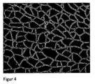
本発明によれば、前面と背面とを備え、脆い材料から成るターゲットプレートを有してなるスパッタリングターゲットが提供され、ここで、このターゲットプレートは、バッキングプレートと全面に亘って接合されており、且つ、このターゲットプレートは、ターゲットプレートの前面から背面へ貫通し、ターゲットプレートを互いに隣接する断片に分割するマイクロクラックを有している。 According to the present invention, there is provided a sputtering target comprising a front plate and a back plate, and having a target plate made of a brittle material, wherein the target plate is bonded to the backing plate over the entire surface, The target plate has a microcrack that penetrates from the front surface to the back surface of the target plate and divides the target plate into adjacent pieces.
ターゲットプレートの材料(材料A)は、バッキングプレートの材料(材料B)よりも大きい膨張係数を有する。こうして、ターゲットプレートは少なくとも中央部において引張応力を受け、これによって、ターゲットプレートに複数のマイクロクラックが発生する。 The target plate material (material A) has a larger coefficient of expansion than the backing plate material (material B). Thus, the target plate is subjected to tensile stress at least in the central portion, thereby generating a plurality of microcracks in the target plate.
この場合、これらの断片の長さ及び幅は、好適には、平均で、ほぼ、そのターゲットプレートの厚さである。 In this case, the length and width of these pieces are preferably, on average, approximately the thickness of the target plate.
これらのマイクロクラックにより、このスパッタリングプロセスの間に注入された高い出力密度において、これらの断片の縁が互いにずれることができるので、発生する応力は、より小さくなる。 These microcracks allow the generated stress to be smaller because the edges of these pieces can be offset from each other at the high power density injected during this sputtering process.
本発明によるスパッタリングターゲットはどのようにして製造することができるかを、以下に、実施例により、図を基に説明する。セラミックのスパッタリングターゲット(ここではTiB2)の場合には、ボンディングプロセスにより機械的な引張応力を減少させるマイクロクラックが発生するように、そのスパッタリングターゲットが、機械的に安定なバッキングプレート(ここではモリブデンから成る)に、ボンディングされる。 Examples of how the sputtering target according to the present invention can be manufactured will be described below with reference to the drawings. In the case of a ceramic sputtering target (here TiB 2 ), the sputtering target has a mechanically stable backing plate (here molybdenum) so that the bonding process generates microcracks that reduce the mechanical tensile stress. To be bonded.
ここで再度留意すべきは、脆いと言われる材料のグループに分類されるセラミックスパッタリングターゲットを使用することは、スパッタリングにおける大きな挑戦課題である、ということである。特に、高いスパッタリング出力の適用(高出力密度の注入)は、熱的に誘起される機械的な応力(ターゲットの破断を導びきかねない応力)を避けるために、非常に良好な冷却を必要とする。良好な冷却を保証するために、しばしば、ターゲットには、フレキシブルな膜を介して高い冷却水圧力がかけられる。これにより、ターゲットに機械的な曲げ負荷が与えられる。一般的には、上述したターゲット材料のグループ(脆い、特にセラミックの、スパッタリングターゲット)の機械的安定性(強度及び延性)は、単独では、この機械的負荷には十分耐えられない。 It should be noted again that the use of ceramic sputtering targets that fall into the group of materials said to be brittle is a major challenge in sputtering. In particular, the application of high sputtering power (high power density implantation) requires very good cooling to avoid thermally induced mechanical stress (stress that could lead to target breakage). To do. In order to ensure good cooling, the target is often subjected to high cooling water pressure through a flexible membrane. Thereby, a mechanical bending load is given to the target. In general, the mechanical stability (strength and ductility) of the above-mentioned group of target materials (brittle, especially ceramic, sputtering target) alone cannot sufficiently withstand this mechanical load.
更に、スパッタリングターゲットを相応の成膜装置内に固定するのに必要となる複雑な形状、例えば、窪み、孔又はバヨネット機構、は、製造するのが非常に難しく、非常に高コストでしか製造できない。従って、脆い(例えば、セラミック)材料のグループから成るターゲットプレートは、ボンディングプロセス(ろう付けプロセス)によりバッキングプレートに固定される。 Furthermore, the complex shapes required to fix the sputtering target in the corresponding film deposition apparatus, such as depressions, holes or bayonet mechanisms, are very difficult to manufacture and can only be manufactured at very high cost. . Thus, a target plate consisting of a group of brittle (eg ceramic) materials is fixed to the backing plate by a bonding process (brazing process).
本発明によるスパッタリングターゲットの好適な形状は、円形又は四角形のプレートであり、好適な寸法は、約50〜300mmの直径ないし、ほぼ、50〜1,000mmの大きさである。 The preferred shape of the sputtering target according to the present invention is a circular or square plate, and the preferred dimensions are about 50 to 300 mm in diameter or approximately 50 to 1,000 mm in size.
このスパッタリングターゲットは、以下のようにして作ることができる。
−好適には主要構成部として脆い物質を含んでいる、ターゲットプレートの準備。
−バッキングプレートの準備。
−ターゲットプレート−バッキングプレート複合体を生じるための、好適には400℃〜1,000℃の温度でのろう付けによるターゲットプレートとバッキングプレートとの全面に亘る有効な接合(Wirkverbindungen)及びターゲットの冷却。
This sputtering target can be made as follows.
-Preparation of the target plate, preferably containing a brittle substance as the main component.
-Preparation of backing plate.
-Target plate-backing plate complex, effective bonding over the entire surface of the target plate and the backing plate, preferably by brazing at a temperature of 400 ° C to 1000 ° C and cooling of the target .
この場合、バッキングプレート物質はターゲットプレート物質と比べて以下の特性を有する。
−より小さい熱膨張係数
−より大きい強度(降伏強度ないし0.2%の伸び限界ないし引張強度)
In this case, the backing plate material has the following characteristics compared to the target plate material.
-Smaller coefficient of thermal expansion-greater strength (yield strength or 0.2% elongation limit or tensile strength)
更に、有利な実施形態では、バッキングプレート物質は、ターゲットプレート物質と比べて以下の特性を有する。
−より大きいヤング率
−より大きい熱伝導率
Further, in an advantageous embodiment, the backing plate material has the following properties compared to the target plate material:
-Greater Young's modulus-greater thermal conductivity
ターゲットプレートとバッキングプレートとは、本発明によるスパッタリングターゲットを製造するために互いに接合される。 The target plate and backing plate are joined together to produce a sputtering target according to the present invention.
この場合、ボンディングろう材の厚さは、十分の数ミリメートルでしかなく、熱伝導及びターゲットプレートのバッキングプレートへの機械的接合の機能を果たす。 In this case, the thickness of the bonding brazing material is only a few millimeters, which serves for heat conduction and mechanical joining of the target plate to the backing plate.
この場合、ターゲットプレートは円板又は長方形プレートのような単純な形をとることができる。 In this case, the target plate can take a simple shape such as a disc or a rectangular plate.
ボンディングプロセスは、以下の要求特性を満たさなければならない。
−ターゲットプレート上の均質な温度分布を可能にするための、ボンディング材料(ボンディングろう材)の面全体に亘る濡れ。もし、面全体にわたる濡れが達成されていない場合には、ターゲットプレートからバッキングプレートへの熱伝達が制限されるので、スパッタリングターゲットが強く加熱され、その結果、ボンディングろう材も高温に達する。ボンディングろう材の融点を超えると、ターゲットプレートのバッキングプレートからの完全な分離が生じる。不均質な温度分布の場合には、熱的に誘起された機械的な応力が発生し、これはターゲットプレートの破断を導きかねない(この場合、破断した破片の剥離による故障)。
−ボンディング材料の良好な熱伝導性。
−高い接着力。
−高いスパッタリング出力密度を適用可能とするための、ボンディング材料の高い融点。
The bonding process must meet the following required characteristics:
-Wetting across the surface of the bonding material (bonding brazing material) to allow a homogeneous temperature distribution on the target plate. If wetting over the entire surface is not achieved, heat transfer from the target plate to the backing plate is limited, so that the sputtering target is heated strongly, and as a result, the bonding brazing material reaches a high temperature. When the melting point of the bonding brazing material is exceeded, complete separation of the target plate from the backing plate occurs. In the case of an inhomogeneous temperature distribution, a thermally induced mechanical stress is generated, which can lead to the fracture of the target plate (in this case a failure due to peeling of the broken pieces).
-Good thermal conductivity of the bonding material.
-High adhesion.
A high melting point of the bonding material in order to be able to apply a high sputtering power density.
現在では、脆い、特にセラミックの、ターゲットプレートをバッキングプレートにボンディングするために、以下の方法が常用されている。
1.インジウムボンディング:
利点:非常に容易に使用可能。インジウムボンディングろう材の大きい熱伝導性。
欠点:インジウムの融点が156℃であるので、スパッタリングプロセスにおいて低い出力密度しか適用できない。
2.AgSn(銀−錫 ろう材)ボンディング:
利点:インジウムよりも幾分高い、即ち、220℃の融点。
欠点:適用がより困難、濡れ及び面全体への適用がより困難。場合によっては、より高コストの「ナノフォイル(Nanofoil)」プロセスの適用。より小さい熱伝導性。
3.電気伝導性及び熱伝導性を有する接着剤の使用による接着。
利点:より高い温度耐性。
欠点:低熱伝導性、これによる、スパッタリングプロセスにおけるターゲットの高温。このことにより、接着剤の熱安定性が或る特定の温度に制限されている場合に、接合の破損。
Currently, the following methods are commonly used to bond a brittle, especially ceramic, target plate to a backing plate.
1. Indium bonding:
Advantage: Very easy to use. High thermal conductivity of indium bonding brazing material.
Disadvantages: Since the melting point of indium is 156 ° C., only low power density can be applied in the sputtering process.
2. AgSn (silver-tin brazing material) bonding:
Advantage: somewhat higher than indium, ie 220 ° C. melting point.
Disadvantages: More difficult to apply, more difficult to wet and apply to the entire surface. In some cases, application of higher cost “Nanofoil” processes. Less thermal conductivity.
3. Adhesion through the use of adhesives with electrical and thermal conductivity.
Advantage: Higher temperature resistance.
Disadvantages: low thermal conductivity, thereby high temperature of the target in the sputtering process. This breaks the bond when the thermal stability of the adhesive is limited to a certain temperature.
インジウムボンディングでは、インジウムろう材使用時の低い融点により、又は、ボンディングろう材の非全面的な濡れにより、又は、このボンディングろう材の低熱伝導性により、セラミックのターゲットプレートの脆い特性と相俟って、適用可能なスパッタリング出力密度は、例えば約5〜10W/cm2に、制限される。この場合、達成可能な成膜速度は小さい。 Indium bonding is coupled with the brittle properties of ceramic target plates due to the low melting point when using indium braze, or due to non-overall wetting of the bonding braze, or due to the low thermal conductivity of this bonding braze. Thus, the applicable sputtering power density is limited to, for example, about 5 to 10 W / cm 2 . In this case, the achievable film formation rate is small.
本発明は、スパッタリングターゲット及びその製造方法に関する。脆い、特にセラミックの、ターゲットプレートは、高温に耐えるようにバッキングプレートと接合されていなければならず、この場合、ターゲットプレート及びバッキングプレートの膨張係数が異なることによる熱的な不整合によって、ボンディングプロセス後に、ターゲットプレートに細かいマイクロクラックが発生する。ターゲットプレートの熱膨張係数は、バッキングプレートの熱膨張係数よりも大きくなければならない。 The present invention relates to a sputtering target and a manufacturing method thereof. A brittle, especially ceramic, target plate must be bonded to the backing plate to withstand high temperatures, in this case due to thermal mismatch due to the different expansion coefficients of the target plate and the backing plate. Later, fine microcracks occur in the target plate. The thermal expansion coefficient of the target plate must be greater than the thermal expansion coefficient of the backing plate.
脆い、特にセラミックの、ターゲットプレートとバッキングプレートとの接合は、高温で真空ろう付け法(http://de.wikipedia.org/wiki/Vakuumloeten)(高温ろう付けとも呼ばれる)により行なわれる。この真空ろう付け過程は、通常、400〜1,000℃で行われる。 The joining of the brittle, in particular ceramic, target plate and backing plate is carried out by high temperature vacuum brazing (http://de.wikipedia.org/wiki/Vakuumloeten) (also called high temperature brazing). This vacuum brazing process is usually performed at 400 to 1,000 ° C.
高温ろう付けでは、400℃を超え、好ましくは600℃を超え、更に好ましくは900℃を超え、約1,200℃までの融点を有するろう剤が、好ましく用いられる。このろう付け法は、酸化による損傷を避けるために、好適には真空中で行なわれる。この場合、このろう材は、ろう箔又はろうペーストの形で供給することができる。ろう付け温度からの冷却時に、ターゲットプレートとバッキングプレートとの間の熱膨張係数の差によって、ターゲットプレートに引張応力が生じ、これにより、マイクロクラックが形成される。これは、冷却過程によりターゲットプレートに発生する引張応力がターゲットプレート材料の降伏点を超え、これに起因する膨張が塑性的には生じえない、という条件下で生じる。このための更なる条件は、ターゲットプレートのバッキングプレートへの、専門的に正確な良好な全面に亘る接合である。 For high temperature brazing, brazing agents having a melting point above 400 ° C., preferably above 600 ° C., more preferably above 900 ° C. and up to about 1,200 ° C. are preferably used. This brazing method is preferably performed in a vacuum to avoid oxidative damage. In this case, the brazing material can be supplied in the form of a brazing foil or a brazing paste. Upon cooling from the brazing temperature, the difference in thermal expansion coefficient between the target plate and the backing plate creates a tensile stress on the target plate, thereby forming microcracks. This occurs under the condition that the tensile stress generated in the target plate due to the cooling process exceeds the yield point of the target plate material, and the resulting expansion cannot be plastically generated. A further requirement for this is a professionally precise and good overall joining of the target plate to the backing plate.
ターゲットのバッキングプレートへの硬ろう付けは、真空炉内において無圧下に行なうことができる。 The brazing of the target to the backing plate can be performed under no pressure in a vacuum furnace.
例えば、ターゲットプレートがTiB2から成りバッキングプレートがモリブデンから成っている場合には、ボンディングプロセス及びスパッタリングターゲット(ターゲットプレート/バッキングプレート複合体)の冷却の後、TiB2とMoとの間の熱膨張係数の違いにより、ターゲットプレートに引張応力が生じる。 For example, if the target plate is made of TiB 2 and the backing plate is made of molybdenum, the thermal expansion between TiB 2 and Mo after the bonding process and cooling of the sputtering target (target plate / backing plate composite). A tensile stress is generated in the target plate due to the difference in the coefficient.
TiB2の膨張係数は、8.1μm/℃であり、モリブデンの熱膨張係数は、4.8μm/℃である。 The expansion coefficient of TiB 2 is 8.1 μm / ° C., and the thermal expansion coefficient of molybdenum is 4.8 μm / ° C.
所望により、ろう付け工程の後に、このスパッタリングターゲットを(例えば、サンドブラストによって)磨くことができる。この製造ステップは、1つには、スパッタリングターゲットからの余剰のろう材のクリーニングに役立ち、2つには、ターゲットプレート中にマイクロクラックを形成するための支援的な作用を有する。 If desired, the sputtering target can be polished (eg, by sandblasting) after the brazing process. This manufacturing step serves, in part, to cleaning excess brazing material from the sputtering target and, in part, has a supportive action for forming microcracks in the target plate.
ブラスト物質の衝突(例えば、コランダム粒子を有するサンドブラスト)によりターゲットプレートの表面に応力がもたらされ、この材料には塑性変形能がないので、細かく分割されたマイクロクラックが形成される。更に、ブラスト物質の衝突により、追加的にマイクロクラックの発生が始まり得る。このとき、同時に、ろう付け温度からの冷却後にバッキングプレートに生じていた弾性膨張が取り除かれる。というのは、応力の原因であるターゲットプレートに、上述したように、マイクロクラックが形成しているからである。これにより、スパッタリングターゲット(ターゲットプレート/バッキングプレート複合体)における曲げ応力が低減される。 Blasting material impact (eg, sandblasting with corundum particles) causes stress on the surface of the target plate, and since this material is not plastically deformable, finely divided microcracks are formed. Furthermore, the occurrence of additional microcracks can begin due to the impact of the blast material. At the same time, the elastic expansion that has occurred in the backing plate after cooling from the brazing temperature is removed. This is because, as described above, microcracks are formed in the target plate that is the cause of stress. Thereby, the bending stress in the sputtering target (target plate / backing plate composite) is reduced.
更に、スパッタリングターゲットを成膜装置内で使用する際に、例えば不均質な熱侵入の結果、相応のマイクロクラックが、初めて、又は、更に付加的に形成され得る。 Furthermore, when the sputtering target is used in a film forming apparatus, corresponding microcracks can be formed for the first time or additionally, for example as a result of inhomogeneous heat penetration.
スパッタリングターゲットの使用後又は最大寿命に達したときに、スパッタリングターゲットをろう材の融点を超える温度へ加熱することにより、ターゲットプレートをバッキングプレートから分離することができるので、このバッキングプレートは、新しいスパッタリングターゲットのために再び使用することができる。 The backing plate can be separated from the backing plate by heating the sputtering target to a temperature above the melting point of the brazing material after use of the sputtering target or when the maximum life is reached. Can be used again for the target.
本発明による方法で作られたスパッタリングターゲットは、非常に高いスパッタリング出力密度において使用することができる。というのは、このターゲットプレートは、非常に高い温度まで耐えることができ、且つ、熱伝導性の良いろう材により、バッキングプレートと接合されているからである。 Sputtering targets made with the method according to the invention can be used at very high sputtering power densities. This is because the target plate can withstand a very high temperature and is joined to the backing plate by a brazing material having good thermal conductivity.
本発明による方法で作られたスパッタリングターゲットは、スパッタリングターゲットの背面にかけられる冷却水の高い圧力によって影響されない。というのは、このスパッタリングターゲットは、大きい剛性と大きい強度とを有するバッキングプレートを備えているからである。 The sputtering target made by the method according to the invention is not affected by the high pressure of cooling water applied to the back surface of the sputtering target. This is because the sputtering target includes a backing plate having high rigidity and high strength.
上述したスパッタリングターゲット及び上述した製造方法は、例えば以下の物質対(ターゲットプレート/バッキングプレート)の場合にも、特に有利に使用することができる。 The above-described sputtering target and the above-described manufacturing method can be used particularly advantageously, for example, in the case of the following material pair (target plate / backing plate).
ターゲットプレート:ホウ化物(例えば、TiB2、CrB2、WB)、炭化物(例えば、WC、TiW、SiC)、窒化物(例えば、TiN、AlN)、珪化物(例えば、TiSi2、CrSi2)、酸化物、並びに、ホウ化物、炭化物、窒化物、酸化物及び金属(例えば、Mo、W、Ti、V、Zr)を含む複合体、並びに、Si、Cr、Geのような元素状の脆い物質。 Target plate: boride (for example, TiB 2 , CrB 2 , WB), carbide (for example, WC, TiW, SiC), nitride (for example, TiN, AlN), silicide (for example, TiSi 2 , CrSi 2 ), Oxides and composites containing borides, carbides, nitrides, oxides and metals (eg Mo, W, Ti, V, Zr), and elemental brittle materials such as Si, Cr, Ge .
バッキングプレート:モリブデン、モリブデン合金、モリブデン複合体、タングステン、タングステン合金、タングステン複合体。 Backing plate: molybdenum, molybdenum alloy, molybdenum composite, tungsten, tungsten alloy, tungsten composite.
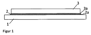
図1において、ターゲットプレート(1)はバッキングプレート(3)の上に載置されている。高温でボンディングろう材(2)は溶融し、接触面3a及び2aを完全に濡らす。 In FIG. 1, the target plate (1) is placed on the backing plate (3). The bonding brazing material (2) melts at a high temperature and completely wets the contact surfaces 3a and 2a.
図2において、TiB2とMoの相異なる熱膨張係数により、ターゲットプレートTiB2に引張応力が生じ、これによりスパッタリングターゲット(ターゲットプレート/バッキングプレート複合体)の湾曲が生じている(ここでは誇張して示されている)。 In FIG. 2, tensile stress is generated in the target plate TiB 2 due to different thermal expansion coefficients of TiB 2 and Mo, which causes the sputtering target (target plate / backing plate composite) to be curved (exaggerated here). Is shown).
図3において、微細なマイクロクラックがターゲットを覆っている。この場合、ろう材は無傷で残っている、即ち、ターゲットプレートのバッキングプレートへの熱的及び機械的な接合が優れている。 In FIG. 3, fine microcracks cover the target. In this case, the brazing material remains intact, ie excellent thermal and mechanical joining of the target plate to the backing plate.
本発明は真空成膜法をも具体的に開示しており、この真空成膜法では、ターゲットのスパッタリングにより塗被されるべき基板の少なくとも1つの表面を塗被するためのスパッタリングターゲットとして、少なくとも1つのターゲットが使用され、ここで、
−前記ターゲットは、前面と背面とを備えた材料Aから成るスパッタリングすべきターゲットプレート、及び、前記ターゲットプレートに面する面を備えた材料Bから成るバッキングプレートを有し、前記ターゲットプレートに面する前記バッキングプレートの面は、材料Cを用いて、ターゲットプレートの背面と全面に亘って機械的に安定に接合されており、
−前記材料Aは、少なくとも大部分が1つ又は複数の脆い物質から成り、前記材料Bは少なくとも大部分が、材料Aの脆い物質よりも大きい延性を有する1つ又は複数の物質から成り、
−材料Aの膨張係数は、材料Bの膨張係数より大きく、材料Bは、材料Aよりも大きい延性及び/又は強度を有し、
−前記ターゲットプレートは少なくとも室温において引張応力下にあり、その結果、ターゲットプレートの前面から背面へ貫通してターゲットプレートを互いに隣接する断片に分割するマイクロクラックが発生し、その結果、ターゲットプレートをスパッタリングするためのスパッタリング出力の適用中に、これらの断片の縁が互いにずれるので、マイクロクラックのないターゲットに比べてターゲットプレート内部に発生する応力がより少なく、これによって、ターゲットプレートが破壊されることなしにより高いスパッタリング出力を適用することができる。
The present invention also specifically discloses a vacuum film-forming method. In this vacuum film-forming method, at least as a sputtering target for coating at least one surface of a substrate to be coated by sputtering of the target, One target is used, where
The target has a target plate to be sputtered made of material A with a front surface and a back surface, and a backing plate made of material B with a surface facing the target plate, facing the target plate; The surface of the backing plate is mechanically and stably bonded to the entire rear surface of the target plate using the material C.
The material A is at least mostly composed of one or more brittle substances, the material B is at least mostly composed of one or more substances having a greater ductility than the brittle substance of material A;
The expansion coefficient of material A is greater than that of material B, which has a greater ductility and / or strength than material A;
The target plate is under tensile stress at least at room temperature, resulting in microcracks that penetrate the target plate from front to back and divide the target plate into adjacent pieces, resulting in sputtering of the target plate Because the edges of these pieces are offset from each other during the application of the sputtering power to reduce the stress generated inside the target plate compared to a target without microcracks, thereby preventing the target plate from being destroyed Higher sputtering power can be applied.
本発明による真空成膜法は、特に、前記材料Aが実質的にTiB2から成り、前記材料Bが実質的にMoから成り、前記バッキングプレートが前記ターゲットプレートに、ろう付けにより400℃〜1,000℃の温度で接合されるように、実施することができる。 In the vacuum film forming method according to the present invention, in particular, the material A is substantially composed of TiB 2 , the material B is substantially composed of Mo, and the backing plate is attached to the target plate at 400 ° C. to 1 ° C. by brazing. Can be carried out at a temperature of 1,000 ° C.
好適な実施形態によれば、本発明による真空成膜法は、成膜が高出力インパルスマグネトロンスパッタリング(HIPIMS、High−power impuls magnetron sputteringとも呼ばれる。)を用いて行なわれるように、実施される。 According to a preferred embodiment, the vacuum deposition method according to the present invention is carried out such that the deposition is performed using high power impulse magnetron sputtering (also called HIPIMS, High-power impulses magnetron sputtering).
1 バッキングプレート
2 ボンディングろう材
3 脆い、特にセラミックの、ターゲットプレート
2a バッキングプレートの接触面
3a ターゲットプレートの接触面
DESCRIPTION OF
Claims (10)
−主要構成部として脆い物質を含んでなるターゲットプレートの準備。
−前記ターゲットプレートの材料よりも小さい熱膨張係数を有する材料からなるバッキングプレートの準備。
−ターゲットプレート−バッキングプレート複合体を生じるための、400℃を超える融点を有するろう材を使用する、400℃〜1,000℃の温度でのろう付けによる、前記ターゲットプレートと前記バッキングプレートとの全面に亘る有効な接合、及び、このターゲットの冷却。 A method of manufacturing a target, comprising the following steps:
-Preparation of a target plate comprising a brittle substance as a main component .
-Preparation of a backing plate made of a material having a smaller coefficient of thermal expansion than the material of the target plate .
The target plate and the backing plate by brazing at a temperature between 400 ° C. and 1,000 ° C. using a brazing material having a melting point above 400 ° C. to produce a target plate-backing plate complex Effective bonding over the entire surface and cooling of this target.
−前記ターゲットは、前面と背面とを備えた材料Aから成るスパッタリングすべきターゲットプレート、及び、前記ターゲットプレートに面する面を備えた材料Bから成るバッキングプレートを有し、前記ターゲットプレートに面する前記バッキングプレートの面は、400℃を超える融点を有する材料Cを用いて、ターゲットプレートの背面と全面に亘って機械的に安定に接合されており、
−前記材料Aは、少なくとも大部分が1つ又は複数の脆い物質から成り、前記材料Bは少なくとも大部分が、材料Aの脆い物質よりも大きい延性を有する1つ又は複数の物質から成り、
−材料Aの膨張係数は、材料Bの膨張係数より大きく、材料Bは、材料Aよりも大きい延性及び/又は強度を有し、
−前記ターゲットプレートは少なくとも室温において引張応力下にあり、その結果、ターゲットプレートの前面から背面へ貫通してターゲットプレートを互いに隣接する断片に分割するマイクロクラックが発生し、その結果、ターゲットプレートをスパッタリングするためのスパッタリング出力の適用中に、これらの断片の縁が互いにずれるので、マイクロクラックのないターゲットに比べてターゲットプレート内部に発生する応力がより少なく、これによって、ターゲットプレートが破壊されることなしにより高いスパッタリング出力を適用することができる、
ことを特徴とする真空成膜法。 A vacuum film-forming method in which at least one target is used as a sputtering target for coating at least one surface of a substrate to be coated by sputtering of the target,
The target has a target plate to be sputtered made of material A with a front surface and a back surface, and a backing plate made of material B with a surface facing the target plate, facing the target plate; The surface of the backing plate is mechanically and stably bonded to the entire back surface of the target plate using the material C having a melting point exceeding 400 ° C. ,
The material A is at least mostly composed of one or more brittle substances, the material B is at least mostly composed of one or more substances having a greater ductility than the brittle substance of material A;
The expansion coefficient of material A is greater than that of material B, which has a greater ductility and / or strength than material A;
The target plate is under tensile stress at least at room temperature, resulting in microcracks that penetrate the target plate from front to back and divide the target plate into adjacent pieces, resulting in sputtering of the target plate Because the edges of these pieces are offset from each other during the application of the sputtering power to reduce the stress generated inside the target plate compared to a target without microcracks, thereby preventing the target plate from being destroyed Higher sputtering power can be applied,
The vacuum film-forming method characterized by this.
Applications Claiming Priority (3)
| Application Number | Priority Date | Filing Date | Title |
|---|---|---|---|
| US201462017909P | 2014-06-27 | 2014-06-27 | |
| US62/017,909 | 2014-06-27 | ||
| PCT/EP2015/001298 WO2015197196A1 (en) | 2014-06-27 | 2015-06-26 | Sputtering target |
Publications (3)
| Publication Number | Publication Date |
|---|---|
| JP2017524831A JP2017524831A (en) | 2017-08-31 |
| JP2017524831A5 JP2017524831A5 (en) | 2018-11-08 |
| JP6567048B2 true JP6567048B2 (en) | 2019-08-28 |
Family
ID=53717965
Family Applications (1)
| Application Number | Title | Priority Date | Filing Date |
|---|---|---|---|
| JP2017519788A Active JP6567048B2 (en) | 2014-06-27 | 2015-06-26 | Sputtering target |
Country Status (10)
| Country | Link |
|---|---|
| US (1) | US10109468B2 (en) |
| EP (1) | EP3161180B1 (en) |
| JP (1) | JP6567048B2 (en) |
| KR (2) | KR102111833B1 (en) |
| CN (1) | CN106471151B (en) |
| BR (1) | BR112016029142A2 (en) |
| MX (1) | MX2016016573A (en) |
| RU (1) | RU2696910C2 (en) |
| TW (1) | TWI713457B (en) |
| WO (1) | WO2015197196A1 (en) |
Families Citing this family (4)
| Publication number | Priority date | Publication date | Assignee | Title |
|---|---|---|---|---|
| AT15050U1 (en) | 2015-12-18 | 2016-11-15 | Plansee Composite Mat Gmbh | Coating source with structuring |
| CN110670030A (en) * | 2019-09-29 | 2020-01-10 | 洛阳丰联科绑定技术有限公司 | Bonding method of ITO spliced target material |
| CN111118459A (en) * | 2019-12-30 | 2020-05-08 | 有研亿金新材料有限公司 | Preparation method of high-performance ferromagnetic target material |
| CN114434107A (en) * | 2022-02-15 | 2022-05-06 | 株洲火炬安泰新材料有限公司 | Production processing method for improving welding rate of ITO target |
Family Cites Families (24)
| Publication number | Priority date | Publication date | Assignee | Title |
|---|---|---|---|---|
| US4209375A (en) * | 1979-08-02 | 1980-06-24 | The United States Of America As Represented By The United States Department Of Energy | Sputter target |
| DE2933835C2 (en) * | 1979-08-21 | 1987-02-19 | Siemens AG, 1000 Berlin und 8000 München | Method for attaching target materials in disc or plate form to cooling plates for sputtering systems |
| US4740429A (en) * | 1985-07-22 | 1988-04-26 | Ngk Insulators, Ltd. | Metal-ceramic joined articles |
| JPS62278261A (en) * | 1986-05-26 | 1987-12-03 | Seiko Epson Corp | Production of target for sputtering |
| JPS63216969A (en) * | 1987-03-05 | 1988-09-09 | Daido Steel Co Ltd | Working method |
| JPS63241167A (en) * | 1987-03-30 | 1988-10-06 | Seiko Epson Corp | Target for sputtering |
| RU2091501C1 (en) * | 1991-04-22 | 1997-09-27 | Акционерное общество открытого типа "Всероссийский алюминиево-магниевый институт" | Method of manufacturing target for magnetron spraying from special- purity aluminium |
| RU2068459C1 (en) * | 1991-06-03 | 1996-10-27 | Центральный научно-исследовательский институт технологии судостроения | Method of working article surface made of steel and copper-base alloys |
| JPH05214518A (en) * | 1992-02-04 | 1993-08-24 | Hitachi Metals Ltd | Method for straightening joined body of sputtering target and backing plate and sputtering target material |
| EP1322796B1 (en) * | 2000-08-17 | 2010-06-02 | Tosoh Smd, Inc. | High purity sputter targets with target end-of-life indication and method of manufacture |
| AT4240U1 (en) | 2000-11-20 | 2001-04-25 | Plansee Ag | METHOD FOR PRODUCING AN EVAPORATION SOURCE |
| US20050072668A1 (en) * | 2003-10-06 | 2005-04-07 | Heraeus, Inc. | Sputter target having modified surface texture |
| MY138584A (en) * | 2003-10-06 | 2009-07-31 | Heraeus Inc | Sputter target having modified surface texture |
| JP4562400B2 (en) * | 2004-01-28 | 2010-10-13 | 京セラ株式会社 | Bonded body using brazing material containing active metal and method for manufacturing the same |
| RU2305717C2 (en) * | 2005-11-14 | 2007-09-10 | Государственное образовательное учреждение высшего профессионального образования "Московский государственный институт стали и сплавов" (технологический университет) | Target for applying functional coatings and method for making it |
| SE533395C2 (en) * | 2007-06-08 | 2010-09-14 | Sandvik Intellectual Property | Ways to make PVD coatings |
| EP2072637B1 (en) * | 2007-12-21 | 2018-08-15 | Sandvik Intellectual Property AB | Coated cutting tool and a method of making a coated cutting tool |
| CN101518851B (en) * | 2009-02-19 | 2011-07-20 | 宁波江丰电子材料有限公司 | Structure and method for welding target material and backboard |
| CN101879640B (en) | 2009-05-06 | 2012-07-25 | 光洋应用材料科技股份有限公司 | Ceramic sputtering target assembly and seaming method thereof |
| KR101237915B1 (en) | 2009-09-30 | 2013-02-27 | 신토고교 가부시키가이샤 | Shot peening treatment method for steel product |
| CN101745710A (en) * | 2010-01-07 | 2010-06-23 | 宁波江丰电子材料有限公司 | Welding method of target assembly |
| JP5437919B2 (en) * | 2010-06-04 | 2014-03-12 | 三井金属鉱業株式会社 | ITO sputtering target and manufacturing method thereof |
| CN102039459B (en) | 2010-11-18 | 2012-09-19 | 宁波江丰电子材料有限公司 | Target material welding method |
| US20130029178A1 (en) * | 2011-07-27 | 2013-01-31 | Shih-Ying Chang | Active solder |
-
2015
- 2015-06-26 RU RU2016147509A patent/RU2696910C2/en active
- 2015-06-26 BR BR112016029142A patent/BR112016029142A2/en not_active Application Discontinuation
- 2015-06-26 CN CN201580034987.1A patent/CN106471151B/en active Active
- 2015-06-26 EP EP15741114.1A patent/EP3161180B1/en active Active
- 2015-06-26 KR KR1020167035948A patent/KR102111833B1/en active IP Right Grant
- 2015-06-26 US US15/319,022 patent/US10109468B2/en active Active
- 2015-06-26 MX MX2016016573A patent/MX2016016573A/en unknown
- 2015-06-26 WO PCT/EP2015/001298 patent/WO2015197196A1/en active Application Filing
- 2015-06-26 KR KR1020187036111A patent/KR20180135120A/en not_active Application Discontinuation
- 2015-06-26 JP JP2017519788A patent/JP6567048B2/en active Active
- 2015-06-29 TW TW104120685A patent/TWI713457B/en active
Also Published As
| Publication number | Publication date |
|---|---|
| US20170133209A1 (en) | 2017-05-11 |
| KR20180135120A (en) | 2018-12-19 |
| WO2015197196A1 (en) | 2015-12-30 |
| JP2017524831A (en) | 2017-08-31 |
| CN106471151B (en) | 2019-06-18 |
| KR20170017936A (en) | 2017-02-15 |
| CN106471151A (en) | 2017-03-01 |
| US10109468B2 (en) | 2018-10-23 |
| EP3161180A1 (en) | 2017-05-03 |
| KR102111833B1 (en) | 2020-05-18 |
| MX2016016573A (en) | 2017-08-18 |
| BR112016029142A2 (en) | 2017-08-22 |
| RU2016147509A (en) | 2018-07-27 |
| RU2016147509A3 (en) | 2018-11-15 |
| TW201615875A (en) | 2016-05-01 |
| TWI713457B (en) | 2020-12-21 |
| RU2696910C2 (en) | 2019-08-07 |
| EP3161180B1 (en) | 2019-02-06 |
Similar Documents
| Publication | Publication Date | Title |
|---|---|---|
| JP6567048B2 (en) | Sputtering target | |
| JP4927102B2 (en) | Target consisting of hard-to-sinter body of refractory metal alloy, refractory metal silicide, refractory metal carbide, refractory metal nitride or refractory metal boride, its manufacturing method, and sputtering target-backing plate assembly and its Production method | |
| WO2018021472A1 (en) | Bonding body, circuit board and semiconductor device | |
| JP5968651B2 (en) | Components for semiconductor manufacturing equipment | |
| KR100775454B1 (en) | Composite body, wafer supporting member using the same, and method for processing wafer | |
| TWI564413B (en) | Backing plate, target assembly and target for supporting | |
| TW200900242A (en) | Reactive multilayer joining with improved metallization techniques | |
| JPH07504945A (en) | Method for joining sputter target backing plate assemblies and assemblies produced thereby | |
| JP2002293655A (en) | Jointing structure of metal terminal and ceramic member, jointing structure of metal member and ceramic member and jointing material for jointing metal terminal and ceramic member | |
| JP2012091975A (en) | Method for manufacturing joined body of ceramic material and metallic material | |
| JP6374084B2 (en) | Target and target manufacturing method | |
| JP2015109139A (en) | Ceramic heater and manufacturing method thereof | |
| JP2017524831A5 (en) | ||
| JP6546953B2 (en) | Sputtering target-backing plate assembly and method for manufacturing the same | |
| JP6068642B2 (en) | Method for manufacturing silicon target structure and silicon target structure | |
| JP7023844B2 (en) | Film formation source with structured material | |
| JP4936877B2 (en) | Bonded body, wafer support member using the same, and wafer processing method | |
| JP5359953B2 (en) | Power module substrate, power module, and method of manufacturing power module substrate | |
| TWI619561B (en) | Rotating target | |
| EP2395547A2 (en) | Substrate having sintered underplate | |
| JP6273734B2 (en) | Flat plate sputtering target and manufacturing method thereof | |
| JP4762064B2 (en) | Bonded body, wafer support member using the same, and wafer processing method |
Legal Events
| Date | Code | Title | Description |
|---|---|---|---|
| A521 | Request for written amendment filed |
Free format text: JAPANESE INTERMEDIATE CODE: A523 Effective date: 20180501 |
|
| A621 | Written request for application examination |
Free format text: JAPANESE INTERMEDIATE CODE: A621 Effective date: 20180501 |
|
| A521 | Request for written amendment filed |
Free format text: JAPANESE INTERMEDIATE CODE: A523 Effective date: 20180927 |
|
| A977 | Report on retrieval |
Free format text: JAPANESE INTERMEDIATE CODE: A971007 Effective date: 20190115 |
|
| A131 | Notification of reasons for refusal |
Free format text: JAPANESE INTERMEDIATE CODE: A131 Effective date: 20190205 |
|
| A601 | Written request for extension of time |
Free format text: JAPANESE INTERMEDIATE CODE: A601 Effective date: 20190422 |
|
| A521 | Request for written amendment filed |
Free format text: JAPANESE INTERMEDIATE CODE: A523 Effective date: 20190513 |
|
| TRDD | Decision of grant or rejection written | ||
| A01 | Written decision to grant a patent or to grant a registration (utility model) |
Free format text: JAPANESE INTERMEDIATE CODE: A01 Effective date: 20190709 |
|
| A61 | First payment of annual fees (during grant procedure) |
Free format text: JAPANESE INTERMEDIATE CODE: A61 Effective date: 20190730 |
|
| R150 | Certificate of patent or registration of utility model |
Ref document number: 6567048 Country of ref document: JP Free format text: JAPANESE INTERMEDIATE CODE: R150 |
|
| R250 | Receipt of annual fees |
Free format text: JAPANESE INTERMEDIATE CODE: R250 |
|
| R250 | Receipt of annual fees |
Free format text: JAPANESE INTERMEDIATE CODE: R250 |
|
| R250 | Receipt of annual fees |
Free format text: JAPANESE INTERMEDIATE CODE: R250 |