JP6566355B2 - Power converter - Google Patents
Power converter Download PDFInfo
- Publication number
- JP6566355B2 JP6566355B2 JP2015180108A JP2015180108A JP6566355B2 JP 6566355 B2 JP6566355 B2 JP 6566355B2 JP 2015180108 A JP2015180108 A JP 2015180108A JP 2015180108 A JP2015180108 A JP 2015180108A JP 6566355 B2 JP6566355 B2 JP 6566355B2
- Authority
- JP
- Japan
- Prior art keywords
- power
- converter
- load
- value
- control unit
- Prior art date
- Legal status (The legal status is an assumption and is not a legal conclusion. Google has not performed a legal analysis and makes no representation as to the accuracy of the status listed.)
- Active
Links
Images


Classifications
-
- G—PHYSICS
- G05—CONTROLLING; REGULATING
- G05F—SYSTEMS FOR REGULATING ELECTRIC OR MAGNETIC VARIABLES
- G05F1/00—Automatic systems in which deviations of an electric quantity from one or more predetermined values are detected at the output of the system and fed back to a device within the system to restore the detected quantity to its predetermined value or values, i.e. retroactive systems
- G05F1/66—Regulating electric power
- G05F1/67—Regulating electric power to the maximum power available from a generator, e.g. from solar cell
-
- H—ELECTRICITY
- H02—GENERATION; CONVERSION OR DISTRIBUTION OF ELECTRIC POWER
- H02J—CIRCUIT ARRANGEMENTS OR SYSTEMS FOR SUPPLYING OR DISTRIBUTING ELECTRIC POWER; SYSTEMS FOR STORING ELECTRIC ENERGY
- H02J3/00—Circuit arrangements for ac mains or ac distribution networks
- H02J3/12—Circuit arrangements for ac mains or ac distribution networks for adjusting voltage in ac networks by changing a characteristic of the network load
- H02J3/14—Circuit arrangements for ac mains or ac distribution networks for adjusting voltage in ac networks by changing a characteristic of the network load by switching loads on to, or off from, network, e.g. progressively balanced loading
-
- H—ELECTRICITY
- H02—GENERATION; CONVERSION OR DISTRIBUTION OF ELECTRIC POWER
- H02J—CIRCUIT ARRANGEMENTS OR SYSTEMS FOR SUPPLYING OR DISTRIBUTING ELECTRIC POWER; SYSTEMS FOR STORING ELECTRIC ENERGY
- H02J3/00—Circuit arrangements for ac mains or ac distribution networks
- H02J3/12—Circuit arrangements for ac mains or ac distribution networks for adjusting voltage in ac networks by changing a characteristic of the network load
- H02J3/16—Circuit arrangements for ac mains or ac distribution networks for adjusting voltage in ac networks by changing a characteristic of the network load by adjustment of reactive power
-
- H—ELECTRICITY
- H02—GENERATION; CONVERSION OR DISTRIBUTION OF ELECTRIC POWER
- H02J—CIRCUIT ARRANGEMENTS OR SYSTEMS FOR SUPPLYING OR DISTRIBUTING ELECTRIC POWER; SYSTEMS FOR STORING ELECTRIC ENERGY
- H02J3/00—Circuit arrangements for ac mains or ac distribution networks
- H02J3/28—Arrangements for balancing of the load in a network by storage of energy
- H02J3/32—Arrangements for balancing of the load in a network by storage of energy using batteries with converting means
-
- H—ELECTRICITY
- H02—GENERATION; CONVERSION OR DISTRIBUTION OF ELECTRIC POWER
- H02J—CIRCUIT ARRANGEMENTS OR SYSTEMS FOR SUPPLYING OR DISTRIBUTING ELECTRIC POWER; SYSTEMS FOR STORING ELECTRIC ENERGY
- H02J3/00—Circuit arrangements for ac mains or ac distribution networks
- H02J3/38—Arrangements for parallely feeding a single network by two or more generators, converters or transformers
- H02J3/381—Dispersed generators
-
- H—ELECTRICITY
- H02—GENERATION; CONVERSION OR DISTRIBUTION OF ELECTRIC POWER
- H02M—APPARATUS FOR CONVERSION BETWEEN AC AND AC, BETWEEN AC AND DC, OR BETWEEN DC AND DC, AND FOR USE WITH MAINS OR SIMILAR POWER SUPPLY SYSTEMS; CONVERSION OF DC OR AC INPUT POWER INTO SURGE OUTPUT POWER; CONTROL OR REGULATION THEREOF
- H02M1/00—Details of apparatus for conversion
- H02M1/08—Circuits specially adapted for the generation of control voltages for semiconductor devices incorporated in static converters
-
- H—ELECTRICITY
- H02—GENERATION; CONVERSION OR DISTRIBUTION OF ELECTRIC POWER
- H02M—APPARATUS FOR CONVERSION BETWEEN AC AND AC, BETWEEN AC AND DC, OR BETWEEN DC AND DC, AND FOR USE WITH MAINS OR SIMILAR POWER SUPPLY SYSTEMS; CONVERSION OF DC OR AC INPUT POWER INTO SURGE OUTPUT POWER; CONTROL OR REGULATION THEREOF
- H02M3/00—Conversion of dc power input into dc power output
- H02M3/02—Conversion of dc power input into dc power output without intermediate conversion into ac
- H02M3/04—Conversion of dc power input into dc power output without intermediate conversion into ac by static converters
- H02M3/10—Conversion of dc power input into dc power output without intermediate conversion into ac by static converters using discharge tubes with control electrode or semiconductor devices with control electrode
- H02M3/145—Conversion of dc power input into dc power output without intermediate conversion into ac by static converters using discharge tubes with control electrode or semiconductor devices with control electrode using devices of a triode or transistor type requiring continuous application of a control signal
- H02M3/155—Conversion of dc power input into dc power output without intermediate conversion into ac by static converters using discharge tubes with control electrode or semiconductor devices with control electrode using devices of a triode or transistor type requiring continuous application of a control signal using semiconductor devices only
-
- H—ELECTRICITY
- H02—GENERATION; CONVERSION OR DISTRIBUTION OF ELECTRIC POWER
- H02M—APPARATUS FOR CONVERSION BETWEEN AC AND AC, BETWEEN AC AND DC, OR BETWEEN DC AND DC, AND FOR USE WITH MAINS OR SIMILAR POWER SUPPLY SYSTEMS; CONVERSION OF DC OR AC INPUT POWER INTO SURGE OUTPUT POWER; CONTROL OR REGULATION THEREOF
- H02M7/00—Conversion of ac power input into dc power output; Conversion of dc power input into ac power output
- H02M7/42—Conversion of dc power input into ac power output without possibility of reversal
- H02M7/44—Conversion of dc power input into ac power output without possibility of reversal by static converters
- H02M7/48—Conversion of dc power input into ac power output without possibility of reversal by static converters using discharge tubes with control electrode or semiconductor devices with control electrode
- H02M7/53—Conversion of dc power input into ac power output without possibility of reversal by static converters using discharge tubes with control electrode or semiconductor devices with control electrode using devices of a triode or transistor type requiring continuous application of a control signal
- H02M7/537—Conversion of dc power input into ac power output without possibility of reversal by static converters using discharge tubes with control electrode or semiconductor devices with control electrode using devices of a triode or transistor type requiring continuous application of a control signal using semiconductor devices only, e.g. single switched pulse inverters
- H02M7/5387—Conversion of dc power input into ac power output without possibility of reversal by static converters using discharge tubes with control electrode or semiconductor devices with control electrode using devices of a triode or transistor type requiring continuous application of a control signal using semiconductor devices only, e.g. single switched pulse inverters in a bridge configuration
- H02M7/53871—Conversion of dc power input into ac power output without possibility of reversal by static converters using discharge tubes with control electrode or semiconductor devices with control electrode using devices of a triode or transistor type requiring continuous application of a control signal using semiconductor devices only, e.g. single switched pulse inverters in a bridge configuration with automatic control of output voltage or current
-
- Y—GENERAL TAGGING OF NEW TECHNOLOGICAL DEVELOPMENTS; GENERAL TAGGING OF CROSS-SECTIONAL TECHNOLOGIES SPANNING OVER SEVERAL SECTIONS OF THE IPC; TECHNICAL SUBJECTS COVERED BY FORMER USPC CROSS-REFERENCE ART COLLECTIONS [XRACs] AND DIGESTS
- Y02—TECHNOLOGIES OR APPLICATIONS FOR MITIGATION OR ADAPTATION AGAINST CLIMATE CHANGE
- Y02B—CLIMATE CHANGE MITIGATION TECHNOLOGIES RELATED TO BUILDINGS, e.g. HOUSING, HOUSE APPLIANCES OR RELATED END-USER APPLICATIONS
- Y02B70/00—Technologies for an efficient end-user side electric power management and consumption
- Y02B70/30—Systems integrating technologies related to power network operation and communication or information technologies for improving the carbon footprint of the management of residential or tertiary loads, i.e. smart grids as climate change mitigation technology in the buildings sector, including also the last stages of power distribution and the control, monitoring or operating management systems at local level
- Y02B70/3225—Demand response systems, e.g. load shedding, peak shaving
-
- Y—GENERAL TAGGING OF NEW TECHNOLOGICAL DEVELOPMENTS; GENERAL TAGGING OF CROSS-SECTIONAL TECHNOLOGIES SPANNING OVER SEVERAL SECTIONS OF THE IPC; TECHNICAL SUBJECTS COVERED BY FORMER USPC CROSS-REFERENCE ART COLLECTIONS [XRACs] AND DIGESTS
- Y04—INFORMATION OR COMMUNICATION TECHNOLOGIES HAVING AN IMPACT ON OTHER TECHNOLOGY AREAS
- Y04S—SYSTEMS INTEGRATING TECHNOLOGIES RELATED TO POWER NETWORK OPERATION, COMMUNICATION OR INFORMATION TECHNOLOGIES FOR IMPROVING THE ELECTRICAL POWER GENERATION, TRANSMISSION, DISTRIBUTION, MANAGEMENT OR USAGE, i.e. SMART GRIDS
- Y04S20/00—Management or operation of end-user stationary applications or the last stages of power distribution; Controlling, monitoring or operating thereof
- Y04S20/20—End-user application control systems
- Y04S20/222—Demand response systems, e.g. load shedding, peak shaving
Landscapes
- Engineering & Computer Science (AREA)
- Power Engineering (AREA)
- Electromagnetism (AREA)
- Sustainable Development (AREA)
- Sustainable Energy (AREA)
- Physics & Mathematics (AREA)
- Life Sciences & Earth Sciences (AREA)
- General Physics & Mathematics (AREA)
- Radar, Positioning & Navigation (AREA)
- Automation & Control Theory (AREA)
- Inverter Devices (AREA)
- Dc-Dc Converters (AREA)
- Rectifiers (AREA)
Description
本発明は、直流電力を交流電力に変換する電力変換装置に関する。 The present invention relates to a power conversion device that converts DC power into AC power.
太陽光発電システムや蓄電池に接続されるパワーコンディショナ(例えば、特許文献1参照)は停電時、系統連系モードから自立運転モードに切り替わり、パワーコンディショナから特定の負荷に電力を供給することができる。自立運転モードにおいて無負荷または軽負荷のとき、パワーコンディショナ内のDC−DCコンバータの出力電流がゼロになる期間が発生する(以下、電流不連続モードという)。電流不連続モードでは急激な負荷変動に応答できないため、自立出力端子の負荷が急激に増加した場合、負荷への電力供給を正常に行うことができくなくなる。例えば、自立出力用のコンセントに電気機器のプラグが差し込まれた際、出力電圧が急低下し、電圧不足で当該電気機器を起動することが困難になる。 A power conditioner (see, for example, Patent Document 1) connected to a photovoltaic power generation system or a storage battery is switched from a grid connection mode to a self-sustaining operation mode at the time of a power failure, and supplies power to a specific load from the power conditioner. it can. When there is no load or light load in the self-sustaining operation mode, a period in which the output current of the DC-DC converter in the power conditioner becomes zero occurs (hereinafter referred to as a current discontinuous mode). Since the current discontinuous mode cannot respond to a sudden load fluctuation, when the load at the self-sustained output terminal increases rapidly, it becomes impossible to normally supply power to the load. For example, when a plug of an electric device is inserted into a stand-alone output outlet, the output voltage drops rapidly, and it becomes difficult to start the electric device due to insufficient voltage.
急激な負荷変動に対して、大型のコンデンサを接続して負荷への電流を維持する方法が考えられる。ただしこの方法ではコスト及び回路面積が増大する。そこで、ダミー負荷を接続してDC−DCコンバータの出力電流がゼロになる期間が発生しないように電流を連続的に流し続ける(以下、電流連続モードという)方法が考えられる。この方法ではダミー負荷の消費電力を抑えることが重要となる。 A method of connecting a large capacitor to maintain a current to the load against a sudden load change is conceivable. However, this method increases cost and circuit area. In view of this, there can be considered a method in which a dummy load is connected and current is continuously supplied so as not to generate a period in which the output current of the DC-DC converter becomes zero (hereinafter referred to as current continuous mode). In this method, it is important to suppress the power consumption of the dummy load.
本発明はこうした状況に鑑みなされたものであり、その目的は、無駄な消費電力を抑えつつ、急激な負荷変動に対応できる電力変換装置を提供することにある。 This invention is made | formed in view of such a condition, The objective is to provide the power converter device which can respond to a sudden load fluctuation, suppressing wasteful power consumption.
上記課題を解決するために、本発明のある態様の電力変換装置は、直流電源から出力される直流電圧を異なるレベルの直流電圧に変換する第1DC−DCコンバータと、前記第1DC−DCコンバータから出力される直流電力を交流電力に変換して交流負荷に供給するDC−ACコンバータと、前記第1DC−DCコンバータと前記DC−ACコンバータの間のノードから分岐される電流路に接続される可変負荷部と、前記交流負荷の消費電力と前記可変負荷部の消費電力の合計値が所定電力値以上となるよう、前記可変負荷部を調整する制御部と、を備える。 In order to solve the above-described problems, a power converter according to an aspect of the present invention includes a first DC-DC converter that converts a DC voltage output from a DC power source into a DC voltage of a different level, and the first DC-DC converter. A DC-AC converter that converts the output DC power into AC power and supplies it to an AC load, and a variable that is connected to a current path branched from a node between the first DC-DC converter and the DC-AC converter. A load unit; and a control unit that adjusts the variable load unit so that a total value of power consumption of the AC load and power consumption of the variable load unit is equal to or greater than a predetermined power value.
なお、以上の構成要素の任意の組み合わせ、本発明の表現を方法、装置、システムなどの間で変換したものもまた、本発明の態様として有効である。 It should be noted that any combination of the above-described constituent elements and a representation of the present invention converted between a method, an apparatus, a system, and the like are also effective as an aspect of the present invention.
本発明によれば、無駄な消費電力を抑えつつ、急激な負荷変動に対応できる電力変換装置を実現できる。 ADVANTAGE OF THE INVENTION According to this invention, the power converter device which can respond to a sudden load fluctuation is realizable, suppressing useless power consumption.
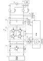
図1は、本発明の実施の形態に係る電力変換装置20の構成を説明するための図である。電力変換装置20は直流電源10と系統30との間に設置され、直流電源10から供給される直流電力を交流電力に変換して系統30に逆潮流させる。本実施の形態では直流電源10として太陽電池を想定し、電力変換装置20が太陽電池により発電された直流電力を交流電力に変換するパワーコンディショナとして機能する例を説明する。
FIG. 1 is a diagram for explaining a configuration of a
パワーコンディショナとして機能する電力変換装置20は、基本構成として第1DC−DCコンバータ21、DC−ACコンバータ22及び制御部25を備える。DC−ACコンバータ22はインバータ部22aとフィルタ部22bを含む。電力変換装置20は、系統連系モードと自立運転モードを有し、停電時、系統連系モードから自立運転モードに切り替わる。電力変換装置20の出力となるフィルタ部22bの出力経路は2つに分岐され、系統連系用の経路は系統連系スイッチRY1を介して系統連系端子T1に繋がり、自立出力用の経路は自立出力スイッチRY2を介して自立出力端子T2に繋がる。系統連系スイッチRY1及び自立出力スイッチRY2には例えば、リレーを使用することができる。
The
制御部25は系統連系モードでは、系統連系スイッチRY1をオン状態に制御し、自立出力スイッチRY2をオフ状態に制御する。自立運転モードでは、系統連系スイッチRY1をオフ状態に制御し、自立出力スイッチRY2をオン状態に制御する。本明細書では自立運転モード時の電力変換装置20の動作に注目する。自立出力端子T2には交流負荷40が接続され、停電時にも直流電源10から給電を受けることができる。
In the grid connection mode, the
例えば、電力変換装置20が家庭用の小型パワーコンディショナである場合、当該パワーコンディショナの筐体に自立出力端子T2としてACコンセントが設けられることが多い。また室内の非常用ACコンセントと自立出力端子T2が配線接続されていてもよい。ユーザは停電時、電気製品のACプラグを当該ACコンセントに差し込むことにより、当該電気製品を使用することができる。
For example, when the
また電力変換装置20がオフィスやマンション用の大型パワーコンディショナである場合、自立出力端子T2と特定の交流負荷40(例えば、照明灯やエレベータ)を予め接続しておいてもよい。
Moreover, when the
第1DC−DCコンバータ21は、直流電源10から出力される直流電圧を異なるレベルの直流電圧に変換してDC−ACコンバータ22に出力する。図1では第1DC−DCコンバータ21として昇圧チョッパを使用する例を描いている。当該昇圧チョッパは、直流電源10としての太陽電池の出力電圧を昇圧してDC−ACコンバータ22に出力する。
The first DC-
当該昇圧チョッパは、第1リアクトルL1、第1ダイオードD1、第1スイッチング素子S1を含む。第1リアクトルL1及び第1ダイオードD1は、直流電源10の正極に接続されるハイサイド基準線に直列に挿入される。第1スイッチング素子S1は、第1リアクトルL1と第1ダイオードD1との間のノードと、直流電源10の負極に接続されるローサイド基準線との間に接続される。
The step-up chopper includes a first reactor L1, a first diode D1, and a first switching element S1. The first reactor L1 and the first diode D1 are inserted in series with a high-side reference line connected to the positive electrode of the
第1スイッチング素子S1には例えば、IGBT(Insulated Gate Bipolar Transistor)またはMOSFET(Metal-Oxide-Semiconductor Field-Effect Transistor)を使用することができる。第2ダイオードD2は還流用のダイオードであり、第1スイッチング素子S1に並列に、逆向きに接続される。第1スイッチング素子S1にMOSFETが使用される場合、ソースからドレイン方向に形成される寄生ダイオードを利用できる。制御部25は、第1スイッチング素子S1のゲート端子に入力する駆動信号により、第1スイッチング素子S1のデューティ比を制御して、当該昇圧チョッパの昇圧率を調整する。なお図1では第1DC−DCコンバータ21として昇圧チョッパを使用する例を示したが、絶縁型DC−DCコンバータ等の他のコンバータを使用してもよい。
For example, an IGBT (Insulated Gate Bipolar Transistor) or a MOSFET (Metal-Oxide-Semiconductor Field-Effect Transistor) can be used for the first switching element S1. The second diode D2 is a free-wheeling diode, and is connected in reverse to the first switching element S1 in parallel. When a MOSFET is used for the first switching element S1, a parasitic diode formed in the direction from the source to the drain can be used. The
第1コンデンサC1は第1DC−DCコンバータ21の出力電圧を平滑化する。DC−ACコンバータ22は、第1DC−DCコンバータ21から出力された直流電力を交流電力に変換して出力する。本実施の形態では自立運転モード時を想定しているため、変換した交流電力を交流負荷40に供給する。
The first capacitor C1 smoothes the output voltage of the first DC-
図1ではDC−ACコンバータ22のインバータ部22aをフルブリッジ回路で構成する例を示している。フルブリッジ回路は、ハイサイド基準線とローサイド基準線の間に、第2スイッチング素子S2と第3スイッチング素子S3が直列接続された第1アームと、第4スイッチング素子S4と第5スイッチング素子S5が直列接続された第2アームを含み、第1アームと第2アームが並列接続される。第1アームの中点と第2アームの中点から交流電力が出力される。
FIG. 1 shows an example in which the
第2スイッチング素子S2〜第5スイッチング素子S5には例えば、IGBTを使用できる。第2スイッチング素子S2のコレクタ端子および第4スイッチング素子S4のコレクタ端子がハイサイド基準線に接続される。第3スイッチング素子S3のエミッタ端子および第5スイッチング素子S5のエミッタ端子がローサイド基準線に接続される。第2スイッチング素子S2のエミッタ端子と第3スイッチング素子S3のコレクタ端子が接続され、第4スイッチング素子S4のエミッタ端子と第5スイッチング素子S5のコレクタ端子が接続される。 For example, IGBTs can be used for the second switching element S2 to the fifth switching element S5. The collector terminal of the second switching element S2 and the collector terminal of the fourth switching element S4 are connected to the high side reference line. The emitter terminal of the third switching element S3 and the emitter terminal of the fifth switching element S5 are connected to the low side reference line. The emitter terminal of the second switching element S2 and the collector terminal of the third switching element S3 are connected, and the emitter terminal of the fourth switching element S4 and the collector terminal of the fifth switching element S5 are connected.
第3ダイオードD3〜第6ダイオードD6は還流用のダイオードであり、第2スイッチング素子S2〜第5スイッチング素子S5にそれぞれ並列に、逆向きに接続される。なお第2スイッチング素子S2〜第5スイッチング素子S5にMOSFETを使用する場合、第3ダイオードD3〜第6ダイオードD6は、ソースからドレイン方向に形成される寄生ダイオードを利用できる。 The third diode D3 to the sixth diode D6 are freewheeling diodes and are connected in parallel to the second switching element S2 to the fifth switching element S5 in the opposite direction. In addition, when using MOSFET for 2nd switching element S2-5th switching element S5, the 3rd diode D3-6th diode D6 can utilize the parasitic diode formed in the drain direction from a source | sauce.
フィルタ部22bは、第2リアクトルL2、第3リアクトルL3及び第2コンデンサC2を含み、インバータ部22aから出力される交流電力の高調波成分を減衰させて、インバータ部22aの出力電圧および出力電流を正弦波に近づける。
The
電流検出部23は、DC−ACコンバータ22から出力される交流電流を電流センサCTを用いて検出する。電流検出部23は、電流センサCTで検出された電流の瞬時値を電圧信号に変換して制御部25に出力する。電圧検出部24は、DC−ACコンバータ22から出力される交流電圧の瞬時値を検出して制御部25に出力する。
The
制御部25は電力変換装置20全体を制御する。制御部25の構成は、ハードウェア資源とソフトウェア資源の協働、またはハードウェア資源のみにより実現できる。ハードウェア資源としてアナログ素子、マイクロコンピュータ、DSP、ROM、RAM、FPGA、その他のLSIを利用できる。ソフトウェア資源としてファームウェア等のプログラムを利用できる。
The
制御部25は、電圧指令値をもとにインバータ部22aの駆動信号を生成し、当該駆動信号をインバータ部22aに供給する。本実施の形態では駆動信号としてPWM信号を生成して、第2スイッチング素子S2〜第5スイッチング素子S5のゲート端子に供給する。PWM信号のデューティ比を上げることによりインバータ部22aの出力電力を上げることができ、PWM信号のデューティ比を下げることによりインバータ部22aの出力電力を下げることができる。制御部25は、検出されるDC−ACコンバータ22の出力電圧および/または出力電流をもとに、当該出力電圧および/または出力電流が安定化するよう当該PWM信号のデューティ比を調整する。
The
可変負荷部26は、第1DC−DCコンバータ21とDC−ACコンバータ22の間のノードN1(第1コンデンサC1の後段であることが望ましい。)から分岐される電流路に接続される。可変負荷部26は、自立出力端子T2に接続された交流負荷40を実負荷とした場合の、ダミー負荷としての役割を担う。図1に示す例では、可変負荷部26は固定負荷26a及び第7スイッチS7を含む。固定負荷26a及び第7スイッチS7は、ノードN1と所定の基準電位(例えば、グラウンド電位)との間に直列に接続される。固定負荷26aには例えば、ヒータ抵抗を使用することができる。第7スイッチS7には例えば、半導体スイッチまたはリレーを使用することができる。
The
制御部25は、交流負荷40の消費電力と可変負荷部26の消費電力の合計値が所定電力値以上となるよう可変負荷部26を調整する。即ち、実負荷としての交流負荷40の大きさが、第1DC−DCコンバータ21が間欠動作してしまう大きさの場合(電流不連続モード)、交流負荷40とダミー負荷としての可変負荷部26の合計が、第1DC−DCコンバータ21が間欠動作しない大きさを超えるように(電流連続モード)、ダミー負荷の大きさを調整する。図1に示す例では制御部25は、第7スイッチS7のオン/オフ時間のデューティ比を調整することにより、可変負荷部26で消費される電力を調整する。
The
制御部25は可変負荷部26で消費すべき電力を、交流負荷40に供給される有効電力をもとに決定する。即ち、電力変換装置20から交流負荷40に供給される有効電力を、可変負荷部26を調整するためのパラメータとして使用する。制御部25は、DC−ACコンバータ22の出力電圧および出力電流をもとに、交流負荷40に供給される有効電力を求める。具体的には制御部25は、電流検出部23で検出される瞬時的な電流値と、電圧検出部24で検出される瞬時的な電圧値を乗算して瞬時電力を算出する。制御部25は、瞬時電力の単位周期の平均を算出して有効電力を算出する。なお有効電力は、出力電圧の位相を測定し、回転座標変換により求めてもよい。三相交流の場合、有効電力は回転座標変換により求める。交流負荷40に供給される電力には無効電力も含まれるため、可変負荷部26で消費されるべき電力は、電力変換装置20から出力される電流ではなく有効電力に基づき判断することが精度の観点から望ましい。
The
なお図1に示す例ではDC−ACコンバータ22の出力電流および出力電圧をもとに、交流負荷40に供給される有効電力を算出したが、DC−ACコンバータ22の入力電流および入力電圧をもとに、交流負荷40に供給される有効電力を算出してもよい。この場合、DC−ACコンバータ22の入力側にも電流検出部と電圧検出部を設ける必要があるが、DC−ACコンバータ22の損失の影響を計測値に含めることができるため、第1DC−DCコンバータ21の負荷をより正確に計測することができる。
In the example shown in FIG. 1, the active power supplied to the
図2(a)−(d)は、可変負荷部26を制御する際に使用される所定の電力値を説明するための図である。図2(a)は、所定の電力値を、第1DC−DCコンバータ21が電流連続モードで動作する電力値の範囲と、電流不連続モードで動作する電力値の範囲の境界値に設定する例を示している。即ち、所定の電力値を、第1DC−DCコンバータ21が電流連続モードで動作する下限の電力値に設定する。制御部25は、実負荷とダミー負荷の和が所定の電力値と一致するよう、ダミー負荷の大きさを制御する。具体的には実負荷が低下するとダミー負荷を上昇させ、実負荷が上昇するとダミー負荷を低下させる。
FIGS. 2A to 2D are diagrams for explaining a predetermined power value used when the
なお電流連続モードと電流不連続モードの境界は第1DC−DCコンバータ21の入力電力に依存するため、所定の電力値を固定値ではなく、第1DC−DCコンバータ21の入力電力をパラメータとする変動値としてもよい。制御部25は、第1DC−DCコンバータ21の入力電力に応じて所定の電力値を適応的に変化させる。
Since the boundary between the current continuous mode and the current discontinuous mode depends on the input power of the first DC-
図2(b)は、制御部25が、実負荷とダミー負荷の和が所定の電力値以上となるよう、ダミー負荷の大きさを制御する例である。図2(a)に示したように、実負荷とダミー負荷の和が所定の電力値と一致した状態が最も損失が少ない状態であるが、実負荷の急低下に対して制御部25によるダミー負荷の上昇制御が追従できなくなると、電流不連続モードに突入してしまう。図2(b)に示す例では、マージンを持たせて運用することにより、実負荷の急低下に対して電流不連続モードに突入してしまうことを回避する設定である。
FIG. 2B is an example in which the
図2(c)は、制御部25が、実負荷とダミー負荷の和が、所定の電力値+オフセット値αと一致するよう、ダミー負荷の大きさを制御する例である。図2(b)に示す例と比較して、実負荷とダミー負荷の和が所定の電力値から大きく離れることがなくなるので、損失を抑えることができる。オフセット値αは、想定される実負荷の急低下および使用する制御部25の応答性を考慮して、実負荷の急低下時にも第1DC−DCコンバータ21が電流連続モードを維持することができる値に設定される。設計者は仕様値、実験により得られた実験値、シミュレーションにより得られたシミュレーション値の少なくとも1つに基づき、オフセット値αを設定する。
FIG. 2C illustrates an example in which the
図2(d)は、制御部25が、実負荷とダミー負荷の和が、所定の電力値1と所定の電力値2の間のレンジに収まるよう、ダミー負荷の大きさを制御する例である。所定の電力値1は、上記の所定の電力値に対応する。所定の電力値2は、所定の電力値1との差が、所定の電力値1より小さくなる値に設定される。制御部25は、実負荷とダミー負荷の和が、所定の電力値1を下回るとダミー負荷を上昇させ、実負荷とダミー負荷の和が、所定の電力値2を上回るとダミー負荷を低下させる。
FIG. 2D shows an example in which the
これにより、ダミー負荷のつなぎ過ぎとならない制御が実現でき、かつ実負荷とダミー負荷の和が一定のレンジ内でよいため、制御が容易である。例えば、ダミー負荷の制御単位が大きい場合(例えば、後述の図4参照)、ダミー負荷の大きさを切り替える度に、実負荷とダミー負荷の和が図2(a)−(c)の所定の電力値を上下に超えてしまう現象(チャタリング)が発生し得る。一例としてダミー負荷の制御単位が100W単位で、所定の電力値が150Wの場合、ダミー負荷が100W→200W→100W→200W・・・とチャタリングしてしまう。図2(d)に示すレンジを使用すれば、このようなチャタリングを防止することができる。 As a result, control that does not cause excessive connection of dummy loads can be realized, and the sum of the actual load and the dummy load may be within a certain range, and thus control is easy. For example, when the control unit of the dummy load is large (for example, see FIG. 4 described later), the sum of the actual load and the dummy load is changed to a predetermined value shown in FIGS. 2A to 2C every time the size of the dummy load is switched. A phenomenon (chattering) that exceeds the power value may occur. As an example, if the control unit of the dummy load is 100 W and the predetermined power value is 150 W, the dummy load chatters as 100 W → 200 W → 100 W → 200 W. If the range shown in FIG. 2D is used, such chattering can be prevented.
図3は、変形例1に係る電力変換装置20の構成を説明するための図である。図3に示す電力変換装置20は、図1に示した電力変換装置20と比較して可変負荷部26の構成が異なる。変形例1の可変負荷部26は、補助電源用の第2DC−DCコンバータ26bと、マイコン26cを含み、第2DC−DCコンバータ26bとマイコン26cは、ノードN1と所定の基準電位との間に直列に接続される。第2DC−DCコンバータ26bは、マイコン26cの電源電圧を生成する降圧チョッパである。マイコン26cは、電力変換装置20内において所定の処理を実行する処理装置の一例である。当該処理装置は、図3に示すように制御部25の内部に設けられる装置であってもよいし、外部に設けられる装置であってもよい。制御部25は、補助電源用の第2DC−DCコンバータ26bを制御して可変負荷部26で消費される電力を調整する。具体的には交流負荷40が低下した場合は第2DC−DCコンバータ26bの出力電圧を上昇させ、交流負荷40が上昇した場合は第2DC−DCコンバータ26bの出力電圧を低下させる。
FIG. 3 is a diagram for explaining the configuration of the
図4は、変形例2に係る電力変換装置20の構成を説明するための図である。図4に示す電力変換装置20は、図1に示した電力変換装置20と比較して可変負荷部26の構成が異なる。変形例2の可変負荷部26は、ノードN1と所定の基準電位との間に、第1抵抗R1と第7スイッチS7が直列に接続された第1直列回路と第2抵抗R2と第8スイッチS8が直列に接続された第2直列回路の並列回路を含む。なお並列に接続される直列回路の数は2に限るものではなく、3以上であってもよい。また並列に接続される抵抗の抵抗値は同じであってもよいし、異なっていてもよい。
FIG. 4 is a diagram for explaining the configuration of the
制御部25は、スイッチのオン/オフ期間のデューティ比を調整するのではなく、オン状態に制御するスイッチの数を調整することにより、可変負荷部26で消費される電力を調整する。並列数を多くすれば制御単位を細かくでき、並列数を少なくすれば回路面積およびコストを低減できる。
The
以上説明したように本実施の形態によれば、可変負荷部26を第1DC−DCコンバータ21の出力に接続することにより、自立運転モード時において、無駄な消費電力を抑えつつ、急激な交流負荷40の変動に対応できる。即ち、第1DC−DCコンバータ21が電流不連続モードに突入することを回避でき、交流負荷40の電圧不足を回避できる。
As described above, according to the present embodiment, by connecting the
また変形例1によれば、マイコン26c等の処理装置の消費電力により、第1DC−DCコンバータ21の電流連続モードを維持することにより、ヒータ抵抗などの負荷を使用する場合と比較して、無駄な損失を低減することができる。また変形例2によれば、スイッチのデューティ制御が不要になるため、制御系の構成を簡素化することができる。
Further, according to the first modification, the current continuous mode of the first DC-
以上、本発明を実施の形態をもとに説明した。実施の形態は例示であり、それらの各構成要素や各処理プロセスの組み合わせにいろいろな変形例が可能なこと、またそうした変形例も本発明の範囲にあることは当業者に理解されるところである。 The present invention has been described based on the embodiments. The embodiments are exemplifications, and it will be understood by those skilled in the art that various modifications can be made to combinations of the respective constituent elements and processing processes, and such modifications are within the scope of the present invention. .
上述の実施の形態では直流電源10として太陽電池を想定したが、燃料電池や蓄電池であってもよい。蓄電池の場合、系統30からの交流電力を電力変換装置20で直流電力に変換して蓄電池に充電することもできる。この場合、第1DC−DCコンバータ21及びDC−ACコンバータ22には、それぞれ双方向タイプが用いられる。
In the above-described embodiment, a solar cell is assumed as the
上述の実施の形態ではDC−ACコンバータ22、系統30、及び交流負荷40が単相交流の例を示したが、DC−ACコンバータ22、系統30、及び交流負荷40が三相交流の場合にも適用可能である。
In the above-described embodiment, an example in which the DC-AC converter 22, the
上述の実施の形態では、電力変換装置20として系統連系モードと自立運転モードを有するパワーコンディショナを想定したが、上述の実施の形態に係る技術は、系統連系しない電力変換装置20にも適用可能である。例えば、照明灯に固定的に接続されている用途でも、照度センサに応じて点灯/消灯する際に負荷変動が生じるため、本技術が有効である。
In the above-described embodiment, the power conditioner having the grid interconnection mode and the independent operation mode is assumed as the
なお、実施の形態は、以下の項目によって特定されてもよい。 The embodiment may be specified by the following items.
[項目1]
直流電源(10)から出力される直流電圧を異なるレベルの直流電圧に変換する第1DC−DCコンバータ(21)と、
前記第1DC−DCコンバータ(21)から出力される直流電力を交流電力に変換して交流負荷(40)に供給するDC−ACコンバータ(22)と、
前記第1DC−DCコンバータ(21)と前記DC−ACコンバータ(22)の間のノード(N1)から分岐される電流路に接続される可変負荷部(26)と、
前記交流負荷(40)の消費電力と前記可変負荷部(26)の消費電力の合計値が所定電力値以上となるよう、前記可変負荷部(26)を調整する制御部(25)と、
を備えることを特徴とする電力変換装置(20)。
交流負荷(40)の大きさに応じて、可変負荷部(26)の大きさを変化させることにより、交流負荷(40)の急激な変動に対しても、交流負荷(40)に安定的な電力供給を行うことができる。
[項目2]
前記制御部(25)は、前記交流負荷(40)に供給される有効電力をもとに、前記可変負荷部(26)の消費電力を決定することを特徴とする項目1に記載の電力変換装置(20)。
交流負荷(40)は力率によって電力値が負になることがあるため、力率が小さくなると可変負荷部(26)を適切に制御できなくなるが、有効電力を測定することにより、交流負荷(40)で実際に消費される電力に基づいた、可変負荷部(26)の適切な調整が可能となる。
[項目3]
前記制御部(25)は、前記DC−ACコンバータ(22)の出力電圧および出力電流をもとに、前記交流負荷(40)に供給される有効電力を求めることを特徴とする項目2に記載の電力変換装置(20)。
電力変換装置(20)はDC−ACコンバータ(22)の出力側に電流検出回路と電圧検出回路を設ける構成が一般的であるため、交流負荷(40)に供給される有効電力を、新たな検出回路を追加することなく計測することができる。
[項目4]
前記制御部(25)は、前記DC−ACコンバータ(22)の入力電圧および入力電流をもとに、前記交流負荷(40)に供給される有効電力を求めることを特徴とする項目2に記載の電力変換装置(20)。
これによれば、DC−ACコンバータ(22)の損失も計測することができる。第1DC−DCコンバータ(21)にとっては、DC−ACコンバータ(22)の損失も負荷になるため、より正確に第1DC−DCコンバータ(21)の負荷を計測することができる。
[項目5]
前記可変負荷部(26)は、
前記ノード(N1)に接続され、固定負荷(26a)とスイッチ(S6)とが直列接続された直列回路を含み、
前記制御部(25)は、前記スイッチ(S6)のデューティ比を調整して前記固定負荷(26a)で消費される電力を調整することを特徴とする項目1から4のいずれかに記載の電力変換装置(20)。
簡単な構成で可変負荷部(26)を実現できる。
[項目6]
前記可変負荷部(26)は、
前記ノード(N1)に接続された補助電源用の第2DC−DCコンバータ(26b)と、所定の処理を実行する処理装置(26c)を含み、
前記制御部(25)は、前記第2DC−DCコンバータ(26b)を制御して前記処理装置(26c)で消費される電力を調整することを特徴とする項目1から4のいずれかに記載の電力変換装置(20)。
負荷として抵抗ではなく処理装置を使用することにより、可変負荷部(26)での電力消費を有効活用することができる。
[項目7]
前記所定電力値は、前記第1DC−DCコンバータ(21)の出力電流が連続的に流れる最小の電力値に設定されることを特徴とする項目1から6のいずれかに記載の電力変換装置(20)。
可変負荷部(26)で消費すべき電力の算出が容易となり、より正確に電流不連続モードを回避することができる。
[項目8]
前記制御部(25)は、前記交流負荷(40)の消費電力と前記可変負荷部(26)の消費電力の合計値が、前記所定電力値になるよう、前記可変負荷部(26)を調整することを特徴とする項目1から7に記載の電力変換装置(20)。
第1DC−DCコンバータ(21)の電流不連続モードを回避できる最小の消費電力で、可変負荷部(26)を動作させることができ、可変負荷部(26)での無駄な電力消費をなくすことができる。
[項目9]
前記制御部(25)は、前記交流負荷(40)の消費電力と前記可変負荷部(26)の消費電力の合計値が、前記所定電力値にオフセット値を加えた値となるよう、前記可変負荷部(26)を調整することを特徴とする項目1から7に記載の電力変換装置(20)。
オフセット値がマージンとして作用し、第1DC−DCコンバータ(21)の電流不連続モードをより確実に回避することができる。
[項目10]
前記オフセット値は、前記交流負荷(40)の変動に対して前記第1DC−DCコンバータ(21)の出力電流が途切れない値に設定されることを特徴とする項目9に記載の電力変換装置(20)。
第1DC−DCコンバータ(21)の電流不連続モードを回避しつつ、損失を抑えることができる。
[項目11]
前記制御部(25)は、前記交流負荷(40)の消費電力と前記可変負荷部(26)の消費電力の合計値が、前記所定電力値を下限とした所定のレンジ内に収まるよう、前記可変負荷部(26)を調整することを特徴とする項目1から10に記載の電力変換装置(20)。
可変負荷部(26)の制御単位(分解能)が粗い場合において、可変負荷部26がチャタリングすることを防止することができる。
[項目12]
前記レンジの幅は、前記所定電力値より小さいことを特徴とする項目10に記載の電力変換装置(20)。
ダミー負荷を単純に接続/非接続する制御を行う構成と比較して、無駄な電力消費を確実に減らすことができる。
[項目13]
前記DC−ACコンバータ(22)は、変換した交流電力を通常時において系統に出力し、停電時において前記交流負荷(40)に出力することを特徴とする項目1から12のいずれかに記載の電力変換装置(20)。
自立運転モード時における第1DC−DCコンバータ(21)の電流不連続モードを回避することができる。
[Item 1]
A first DC-DC converter (21) for converting a DC voltage output from the DC power supply (10) into a DC voltage of a different level;
A DC-AC converter (22) that converts DC power output from the first DC-DC converter (21) into AC power and supplies the AC power to the AC load (40);
A variable load section (26) connected to a current path branched from a node (N1) between the first DC-DC converter (21) and the DC-AC converter (22);
A control unit (25) for adjusting the variable load unit (26) so that a total value of the power consumption of the AC load (40) and the power consumption of the variable load unit (26) is equal to or greater than a predetermined power value;
The power converter device (20) characterized by comprising.
By changing the size of the variable load portion (26) according to the size of the AC load (40), the AC load (40) is stable against sudden changes in the AC load (40). Electric power can be supplied.
[Item 2]
The power conversion according to
Since the power value of the AC load (40) may be negative depending on the power factor, the variable load unit (26) cannot be properly controlled when the power factor decreases. However, by measuring the active power, the AC load ( The variable load section (26) can be appropriately adjusted based on the power actually consumed in 40).
[Item 3]
Since the power converter (20) is generally configured to include a current detection circuit and a voltage detection circuit on the output side of the DC-AC converter (22), the active power supplied to the AC load (40) Measurement can be performed without adding a detection circuit.
[Item 4]
According to this, the loss of the DC-AC converter (22) can also be measured. Since the loss of the DC-AC converter (22) also becomes a load for the first DC-DC converter (21), the load of the first DC-DC converter (21) can be measured more accurately.
[Item 5]
The variable load section (26)
A series circuit connected to the node (N1) and having a fixed load (26a) and a switch (S6) connected in series;
The power according to any one of
The variable load section (26) can be realized with a simple configuration.
[Item 6]
The variable load section (26)
A second DC-DC converter (26b) for auxiliary power connected to the node (N1), and a processing device (26c) for executing a predetermined process,
The said control part (25) controls the said 2nd DC-DC converter (26b), and adjusts the electric power consumed by the said processing apparatus (26c), The item in any one of the
By using a processing device instead of a resistor as a load, it is possible to effectively use power consumption in the variable load section (26).
[Item 7]
The power converter according to any one of
Calculation of power to be consumed by the variable load section (26) is facilitated, and the current discontinuous mode can be avoided more accurately.
[Item 8]
The control unit (25) adjusts the variable load unit (26) so that a total value of power consumption of the AC load (40) and power consumption of the variable load unit (26) becomes the predetermined power value. The power conversion device (20) according to
The variable load section (26) can be operated with the minimum power consumption that can avoid the current discontinuous mode of the first DC-DC converter (21), and unnecessary power consumption in the variable load section (26) is eliminated. Can do.
[Item 9]
The control unit (25) is configured so that the total value of the power consumption of the AC load (40) and the power consumption of the variable load unit (26) is a value obtained by adding an offset value to the predetermined power value. The power converter (20) according to
The offset value acts as a margin, and the current discontinuous mode of the first DC-DC converter (21) can be avoided more reliably.
[Item 10]
10. The power conversion device according to
Loss can be suppressed while avoiding the current discontinuous mode of the first DC-DC converter (21).
[Item 11]
The control unit (25) is configured so that a total value of power consumption of the AC load (40) and power consumption of the variable load unit (26) falls within a predetermined range with the predetermined power value as a lower limit. The power converter (20) according to
When the control unit (resolution) of the variable load unit (26) is coarse, the
[Item 12]
The power converter (20) according to
Compared with a configuration in which the dummy load is simply connected / disconnected, wasteful power consumption can be reliably reduced.
[Item 13]
13. The DC-AC converter (22) outputs the converted AC power to the system at normal time and outputs it to the AC load (40) at power failure. A power converter (20).
The current discontinuous mode of the first DC-DC converter (21) during the self-sustaining operation mode can be avoided.
10 直流電源、 20 電力変換装置、 21 第1DC−DCコンバータ、 22 DC−ACコンバータ、 22a インバータ部、 22b フィルタ部、 23 電流検出部、 24 電圧検出部、 25 制御部、 26 可変負荷部、 26a 固定負荷、 26b 第2DC−DCコンバータ、 26c マイコン、 30 系統、 40 交流負荷、 L1 第1リアクトル、 L2 第2リアクトル、 L3 第3リアクトル、 D1 第1ダイオード、 D2 第2ダイオード、 D3 第3ダイオード、 D4 第4ダイオード、 D5 第5ダイオード、 D6 第6ダイオード、 C1 第1コンデンサ、 C2 第2コンデンサ、 S1 第1スイッチング素子、 S2 第2スイッチング素子、 S3 第3スイッチング素子、 S4 第4スイッチング素子、 S5 第5スイッチング素子、 S6 第6スイッチ、 S7 第7スイッチ、 S8 第8スイッチ、 R1 第1抵抗、 R2 第2抵抗、 RY1 系統連系スイッチ、 RY2 自立出力スイッチ。
DESCRIPTION OF
Claims (13)
前記第1DC−DCコンバータから出力される直流電力を交流電力に変換して交流負荷に供給するDC−ACコンバータと、
前記第1DC−DCコンバータと前記DC−ACコンバータの間のノードから分岐される電流路に接続される可変負荷部と、
前記交流負荷の消費電力と前記可変負荷部の消費電力の合計値が所定電力値以上となるよう、前記可変負荷部を調整する制御部と、
を備えることを特徴とする電力変換装置。 A first DC-DC converter that converts a DC voltage output from a DC power source into a DC voltage of a different level;
A DC-AC converter that converts DC power output from the first DC-DC converter into AC power and supplies the AC power to an AC load;
A variable load connected to a current path branched from a node between the first DC-DC converter and the DC-AC converter;
A control unit that adjusts the variable load unit such that a total value of the power consumption of the AC load and the power consumption of the variable load unit is equal to or greater than a predetermined power value;
A power conversion device comprising:
前記ノードに接続され、固定負荷とスイッチとが直列接続された直列回路を含み、
前記制御部は、前記スイッチのデューティ比を調整して前記固定負荷で消費される電力を調整することを特徴とする請求項1から4のいずれかに記載の電力変換装置。 The variable load section is
A series circuit connected to the node and including a fixed load and a switch connected in series;
The said control part adjusts the duty ratio of the said switch, and adjusts the electric power consumed by the said fixed load, The power converter device in any one of Claim 1 to 4 characterized by the above-mentioned.
前記ノードに接続された補助電源用の第2DC−DCコンバータと、所定の処理を実行する処理装置を含み、
前記制御部は、前記第2DC−DCコンバータを制御して前記処理装置で消費される電力を調整することを特徴とする請求項1から4のいずれかに記載の電力変換装置。 The variable load section is
A second DC-DC converter for auxiliary power connected to the node, and a processing device for executing a predetermined process,
5. The power conversion device according to claim 1, wherein the control unit controls the second DC-DC converter to adjust power consumed by the processing device. 6.
Priority Applications (6)
| Application Number | Priority Date | Filing Date | Title |
|---|---|---|---|
| JP2015180108A JP6566355B2 (en) | 2015-09-11 | 2015-09-11 | Power converter |
| NZ73972416A NZ739724A (en) | 2015-09-11 | 2016-08-23 | Power conversion device |
| PCT/JP2016/003837 WO2017043027A1 (en) | 2015-09-11 | 2016-08-23 | Power conversion device |
| AU2016319842A AU2016319842A1 (en) | 2015-09-11 | 2016-08-23 | Power conversion device |
| EP16843900.8A EP3349345A4 (en) | 2015-09-11 | 2016-08-23 | Power conversion device |
| US15/901,490 US20180183317A1 (en) | 2015-09-11 | 2018-02-21 | Power converter |
Applications Claiming Priority (1)
| Application Number | Priority Date | Filing Date | Title |
|---|---|---|---|
| JP2015180108A JP6566355B2 (en) | 2015-09-11 | 2015-09-11 | Power converter |
Publications (2)
| Publication Number | Publication Date |
|---|---|
| JP2017055632A JP2017055632A (en) | 2017-03-16 |
| JP6566355B2 true JP6566355B2 (en) | 2019-08-28 |
Family
ID=58239542
Family Applications (1)
| Application Number | Title | Priority Date | Filing Date |
|---|---|---|---|
| JP2015180108A Active JP6566355B2 (en) | 2015-09-11 | 2015-09-11 | Power converter |
Country Status (6)
| Country | Link |
|---|---|
| US (1) | US20180183317A1 (en) |
| EP (1) | EP3349345A4 (en) |
| JP (1) | JP6566355B2 (en) |
| AU (1) | AU2016319842A1 (en) |
| NZ (1) | NZ739724A (en) |
| WO (1) | WO2017043027A1 (en) |
Families Citing this family (6)
| Publication number | Priority date | Publication date | Assignee | Title |
|---|---|---|---|---|
| WO2017157477A1 (en) * | 2016-03-18 | 2017-09-21 | Hewlett-Packard Development Company L.P. | Power regulation circuit and system |
| JP6668897B2 (en) * | 2016-04-05 | 2020-03-18 | 株式会社オートネットワーク技術研究所 | Power supply control device |
| KR102579294B1 (en) * | 2018-03-02 | 2023-09-18 | 현대자동차주식회사 | Low voltage dc-dc converter for vehicle and control method of the same |
| KR102043061B1 (en) * | 2018-04-05 | 2019-11-11 | 엘지전자 주식회사 | Power converting apparatus and home appliance including the same |
| JP2020145819A (en) * | 2019-03-05 | 2020-09-10 | オムロン株式会社 | Power conditioner |
| CN112054707A (en) * | 2020-08-12 | 2020-12-08 | 中国科学院电工研究所 | Micro inverter applied to high-voltage thin-film photovoltaic module based on switch inductor |
Family Cites Families (5)
| Publication number | Priority date | Publication date | Assignee | Title |
|---|---|---|---|---|
| JPH10302991A (en) * | 1997-04-26 | 1998-11-13 | Pioneer Electron Corp | Driving circuit and driving method for fluorescent lamp |
| JP2002051548A (en) * | 2000-07-31 | 2002-02-15 | Matsushita Electric Works Ltd | Power supply and discharge lamp lighting device |
| JP4765162B2 (en) * | 2000-12-04 | 2011-09-07 | 株式会社Gsユアサ | Power storage type solar power generation system |
| JP5507582B2 (en) * | 2010-01-27 | 2014-05-28 | 三洋電機株式会社 | Power supply method, computer-readable recording medium, and power generation system |
| JP2012079648A (en) * | 2010-10-06 | 2012-04-19 | Mitsubishi Electric Corp | Power processing apparatus |
-
2015
- 2015-09-11 JP JP2015180108A patent/JP6566355B2/en active Active
-
2016
- 2016-08-23 WO PCT/JP2016/003837 patent/WO2017043027A1/en unknown
- 2016-08-23 EP EP16843900.8A patent/EP3349345A4/en not_active Withdrawn
- 2016-08-23 NZ NZ73972416A patent/NZ739724A/en not_active IP Right Cessation
- 2016-08-23 AU AU2016319842A patent/AU2016319842A1/en not_active Abandoned
-
2018
- 2018-02-21 US US15/901,490 patent/US20180183317A1/en not_active Abandoned
Also Published As
| Publication number | Publication date |
|---|---|
| EP3349345A4 (en) | 2018-10-03 |
| WO2017043027A1 (en) | 2017-03-16 |
| JP2017055632A (en) | 2017-03-16 |
| US20180183317A1 (en) | 2018-06-28 |
| EP3349345A1 (en) | 2018-07-18 |
| NZ739724A (en) | 2019-09-27 |
| AU2016319842A1 (en) | 2018-03-01 |
Similar Documents
| Publication | Publication Date | Title |
|---|---|---|
| JP6566355B2 (en) | Power converter | |
| JP6001587B2 (en) | Power converter | |
| Roggia et al. | Digital current controllers applied to the boost power factor correction converter with load variation | |
| KR101864107B1 (en) | Power control system and control method thereof | |
| JP5284447B2 (en) | Distributed power system | |
| US11495966B2 (en) | Solar power generation system and power conditioner | |
| WO2006090672A1 (en) | Power converter | |
| JP2006238628A (en) | Power converting device | |
| US9515557B2 (en) | Step-up step-down converter device | |
| JP6539172B2 (en) | Power supply | |
| US9985553B2 (en) | Control device of inverter | |
| JP4878645B2 (en) | Power converter | |
| JP2014127081A (en) | Power conditioner for photovoltaic power generation | |
| JP2013050850A (en) | Photovoltaic power generation system and control method therefor, and boost unit | |
| JPH10289025A (en) | Power conditioner for solar power generation system | |
| Pichlík et al. | Converter regulation of stand-alone photovoltaic system at low solar radiation | |
| JP5799548B2 (en) | Power generation system | |
| JP4870822B2 (en) | Power converter | |
| JP5837454B2 (en) | Control device | |
| JP6928330B2 (en) | Power control device and its power control method | |
| JP2005137070A (en) | System linkage inverter and power source system | |
| JPH11318087A (en) | Sunlight power generating system | |
| JP6197700B2 (en) | Power converter | |
| JP6422247B2 (en) | Inverter | |
| JP2014176254A (en) | AC power supply device |
Legal Events
| Date | Code | Title | Description |
|---|---|---|---|
| A621 | Written request for application examination |
Free format text: JAPANESE INTERMEDIATE CODE: A621 Effective date: 20180611 |
|
| TRDD | Decision of grant or rejection written | ||
| A01 | Written decision to grant a patent or to grant a registration (utility model) |
Free format text: JAPANESE INTERMEDIATE CODE: A01 Effective date: 20190709 |
|
| A61 | First payment of annual fees (during grant procedure) |
Free format text: JAPANESE INTERMEDIATE CODE: A61 Effective date: 20190719 |
|
| R150 | Certificate of patent or registration of utility model |
Ref document number: 6566355 Country of ref document: JP Free format text: JAPANESE INTERMEDIATE CODE: R150 |