JP6562997B2 - Car body side structure of one-side center pillarless vehicle - Google Patents
Car body side structure of one-side center pillarless vehicle Download PDFInfo
- Publication number
- JP6562997B2 JP6562997B2 JP2017250548A JP2017250548A JP6562997B2 JP 6562997 B2 JP6562997 B2 JP 6562997B2 JP 2017250548 A JP2017250548 A JP 2017250548A JP 2017250548 A JP2017250548 A JP 2017250548A JP 6562997 B2 JP6562997 B2 JP 6562997B2
- Authority
- JP
- Japan
- Prior art keywords
- center
- vehicle
- panel outer
- reinforcing member
- vehicle body
- Prior art date
- Legal status (The legal status is an assumption and is not a legal conclusion. Google has not performed a legal analysis and makes no representation as to the accuracy of the status listed.)
- Active
Links
Images


Classifications
-
- B—PERFORMING OPERATIONS; TRANSPORTING
- B62—LAND VEHICLES FOR TRAVELLING OTHERWISE THAN ON RAILS
- B62D—MOTOR VEHICLES; TRAILERS
- B62D25/00—Superstructure or monocoque structure sub-units; Parts or details thereof not otherwise provided for
- B62D25/02—Side panels
Description
本発明は、片側センタピラーレス車両の車体側部構造に関する。 The present invention relates to a vehicle body side structure of a one-side center pillarless vehicle.
例えば、特許文献1には、センタピラーレス側のフロントコーナー部に補強部材を設けると共に、クロスメンバ部に補強部材を設けた片側センタピラーレス車両が開示されている。 For example, Patent Document 1 discloses a one-side center pillar-less vehicle in which a reinforcing member is provided at a front corner portion on the center pillar-less side and a reinforcing member is provided on a cross member portion.
特許文献1では、片側センタピラーレス車両をこのように構成することで、車体の左右の剛性差をなくすことができるとしている。 In Patent Document 1, it is described that the difference in rigidity between the left and right of the vehicle body can be eliminated by configuring the one-side center pillar-less vehicle in this way.
ところで、センタピラーレス側では、センタピラーが無い分だけドア開口部が大きくなる。特に、ドア開口部の下枠(サイドシル)と前枠(フロントピラー下部)との結合部であるフロントコーナー部の変形が起こりやすくなる。 By the way, on the center pillar-less side, the door opening becomes larger by the absence of the center pillar. In particular, deformation of the front corner portion, which is a connecting portion between the lower frame (side sill) of the door opening and the front frame (lower front pillar), is likely to occur.
この点に関し、特許文献1では、フロントコーナー部とクロスメンバ部とにそれぞれ個別に補強部材を設けている。しかしながら、特許文献1では、フロントコーナー部の補強部材とクロスメンバ部の補強部材との間に配置された部材の剛性が低くなっている。このため、特許文献1に開示された構造では、フロントコーナー部の補強部材とクロスメンバ部の補強部材との間に配置された部材に応力が集中して、車体の左右の剛性差を無くすことが困難である。 In this regard, in Patent Document 1, reinforcing members are individually provided at the front corner portion and the cross member portion, respectively. However, in patent document 1, the rigidity of the member arrange | positioned between the reinforcement member of a front corner part and the reinforcement member of a cross member part is low. For this reason, in the structure disclosed in Patent Document 1, stress concentrates on the member disposed between the reinforcing member of the front corner portion and the reinforcing member of the cross member portion, thereby eliminating the rigidity difference between the left and right sides of the vehicle body. Is difficult.
本発明は、前記の点に鑑みてなされたものであり、フロントコーナー部から本来のセンタピラーがあるべき部位までのサイドシルの剛性を向上させることが可能な片側センタピラーレス車両の車体側部構造を提供することを目的とする。 The present invention has been made in view of the above points, and has a vehicle body side part structure for a one-side center pillar-less vehicle capable of improving the rigidity of a side sill from a front corner portion to a portion where an original center pillar should be. The purpose is to provide.
前記の目的を達成するために、本発明は、片側センタピラーレス車両の車体側部構造において、センタピラーレス側の第1サイドパネルアウタ及び前記第1サイドパネルアウタに設けられた第1ドア開口部と、センタピラーを有する側の第2サイドパネルアウタ及び前記第2サイドパネルアウタに設けられた第2ドア開口部と、前記第1ドア開口部のフロントコーナー部を補強するフロント補強部材と、前記第1サイドパネルアウタのサイドシルにおいて、前記第2サイドパネルアウタのサイドシルと前記センタピラーとが接続される位置に対応するセンタ部を補強するセンタ補強部材と、を備え、前記第1サイドパネルアウタは、前記フロントコーナー部から前記センタ部にかけて、前記第2サイドパネルアウタの同じ部位よりも剛性の高い高剛性部を有し、前記フロント補強部材及び前記センタ補強部材は、それぞれ前記高剛性部に接合されていることを特徴とする。 In order to achieve the above object, according to the present invention, in a vehicle body side part structure of a one-side center pillar-less vehicle, a first side panel outer on a center pillar-less side and a first door opening provided in the first side panel outer; A second side panel outer on the side having a center pillar, a second door opening provided in the second side panel outer, a front reinforcing member for reinforcing a front corner portion of the first door opening, In the side sill of one side panel outer, a center reinforcing member that reinforces a center portion corresponding to a position where the side sill of the second side panel outer and the center pillar are connected, the first side panel outer is Higher rigidity than the same part of the second side panel outer from the front corner portion to the center portion Has a high rigidity portion, said front reinforcement member and the center reinforcement member is characterized by being respectively joined to the high rigidity portion.
なお、「対応する」とは、センタピラーレス側の第1サイドパネルアウタの一部分と、センタピラーを有する第2サイドパネルアウタの一部分とが、車両前後方向でそれぞれ同じ位置であることをいう。 “Corresponding” means that a part of the first side panel outer on the center pillar-less side and a part of the second side panel outer having the center pillar are at the same position in the vehicle front-rear direction.
本発明では、フロントコーナー部から本来のセンタピラーがあるべき部位までのサイドシルの剛性を向上させることが可能な片側センタピラーレス車両の車体側部構造を得ることができる。 According to the present invention, it is possible to obtain a vehicle body side structure of a one-side center pillar-less vehicle that can improve the rigidity of the side sill from the front corner portion to the portion where the original center pillar should be.
次に、本発明の実施形態について、適宜図面を参照しながら詳細に説明する。 Next, embodiments of the present invention will be described in detail with reference to the drawings as appropriate.
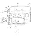
図1に示されるように、本発明の実施形態に係る車体側部構造が適用された車両(片側センタピラーレス車両)10は、センタピラーレス側の車体左側部12aと、車幅方向に沿った反対側に配置されたセンタピラー14を有する側の車体右側部12bとを備えて構成されている。センタピラーレス側の車体左側部12aは、車幅方向に沿った一側に配置されている。センタピラー14を有する側の車体右側部12bは、車幅方向に沿った他側に配置されている。
As shown in FIG. 1, a vehicle (one-side center pillar-less vehicle) 10 to which a vehicle body side structure according to an embodiment of the present invention is applied is opposite to a vehicle body
車体左側部12aは、車体左側部12aの外側に設けられた第1サイドパネルアウタ16(図2参照)と、車体左側部12aの内側に設けられた第1サイドパネルインナ17(図4(a)参照)とを備えている。車体右側部12bは、車体右側部12bの外側に設けられた第2サイドパネルアウタ18(図2参照)と、車体右側部12bの内側に設けられた第2サイドパネルインナ19(図4(b)参照)とを備えている。
The vehicle body
第1サイドパネルアウタ16は、車体左側部12aの外側壁を構成するパネルである。図2に示されるように、この第1サイドパネルアウタ16は、サイドシルアウタ20と、フロントピラーアウタ22と、リヤピラーアウタ24と、ルーフサイドレールアウタ26とを有する。サイドシルアウタ20及びフロントピラーアウタ22の下部側は、一体的に形成された高剛性部28を構成している。この「高剛性部28」については、後記で詳細に説明する。
The 1st side panel outer 16 is a panel which comprises the outer side wall of the vehicle body
また、第1サイドパネルアウタ16には、側面視して略矩形状のドア開口部(第1ドア開口部)30が形成されている。このドア開口部30は、サイドシルアウタ20と、フロントピラーアウタ22と、リヤピラーアウタ24と、ルーフサイドレールアウタ26とによって囲繞された内部空間によって形成されている。 Further, the first side panel outer 16 is formed with a substantially rectangular door opening (first door opening) 30 in a side view. The door opening 30 is formed by an internal space surrounded by the side sill outer 20, the front pillar outer 22, the rear pillar outer 24, and the roof side rail outer 26.
図1に示されるように、第2サイドパネルアウタ18は、車体右側部12bの外側壁を構成するパネルである。この第2サイドパネルアウタ18は、サイドシルアウタ32と、フロントピラーアウタ34と、センタピラーアウタ36と、リヤピラーアウタ38と、ルーフサイドレールアウタ40とを有する。
As shown in FIG. 1, the second side panel outer 18 is a panel constituting the outer wall of the vehicle body
また、第2サイドパネルアウタ18には、車両前後方向に沿って2つのドア開口部が形成されている。この2つのドア開口部は、センタピラー14の車両前方に位置する前側ドア開口部42と、センタピラー14の車両後方に位置する後側ドア開口部44とから構成されている。なお、前側ドア開口部42及び後側ドア開口部44は、第2ドア開口部として機能するものである。
The second side panel outer 18 is formed with two door openings along the vehicle longitudinal direction. The two door openings are constituted by a front door opening 42 positioned in front of the
第1サイドパネルアウタ16に形成されたドア開口部30は、第2サイドパネルアウタ18に形成された前側ドア開口部42及び後側ドア開口部44よりも大きな開口面積を有する。また、ドア開口部30の開口面積は、前側ドア開口部42の開口面積と後側ドア開口部44の開口面積とをそれぞれ加算した合計開口面積よりも大きくなっている。
The door opening 30 formed in the first side panel outer 16 has a larger opening area than the front door opening 42 and the
図2に示されるように、センタピラーレス側の第1サイドパネルアウタ16は、フロントコーナー部46から、サイドシルとセンタピラーとの結合部であるセンタ部48を経由してリヤピラーまで延出する高剛性部28を備えている。なお、センタ部48は、センタピラー14を有する側の車体右側部12bのサイドシルとセンタピラー14との結合部と車両前後方向で同じ位置となっている。
As shown in FIG. 2, the first side panel outer 16 on the center pillar-less side has a high rigidity that extends from the
この高剛性部28は、サイドシルアウタ20と、フロントピラーアウタ22の下部側とが側面視して略L字状に一体的に形成されている。高剛性部28は、センタピラー14を有する第2サイドパネルアウタ18のサイドシルアウタ32及びフロントピラーアウタ34と比較して、その剛性・強度が高くなっている。例えば、本実施形態において、センタピラーレス側の第1サイドパネルアウタ16の板厚は、センタピラー14を有する第2サイドパネルアウタ18の板厚よりも厚くなっている。また、高剛性部28は、第1サイドパネルアウタ16の他の部位よりも剛性・強度が高くなっている。高剛性部28の剛性・強度の高度化は、例えば、板厚の増加や、超高張力鋼板の使用等によって行われる。
The
なお、図2に示されるように、高剛性部28の車両後方端部28aは、リヤピラーアウタ24の下方まで延出している。フロントピラーアウタ34で形成された高剛性部28の車両前方側の上端28bは、フロントピラーアウタ22の中央から上方まで延出している。
As shown in FIG. 2, the vehicle
高剛性部28のフロントコーナー部46には、側面視して略L字状を呈するフロント補強部材50が接合されている。また、高剛性部28のセンタ部48には、車両前後方向に沿って略直線状に延在するセンタ補強部材52が接合されている。
A front reinforcing
なお、「センタ部」とは、フロント補強部材50の車両後方端部から車両後方で、第1サイドパネルアウタ16のサイドシルにおいて、第2サイドパネルアウタ18のサイドシルとセンタピラー14とが接続される位置に対応する位置をいう。「フロントコーナー部」とは、フロントピラーの下端とサイドシルの車両前方端部とが結合される部位をいう。
The “center portion” refers to the side sill of the first side panel outer 16 connected to the side sill of the second side panel outer 18 and the
図9及び図10に示されるように、高剛性部28のサイドシル部分の軸直断面は、略ハット状を呈し、上部フランジ部54aと、上面部54bと、湾曲部54cと、側壁部54dと、下面部54eと、下部フランジ部54fとから構成されている。
As shown in FIGS. 9 and 10, the axial straight section of the side sill portion of the high-
センタ補強部材52は、その軸直断面において略ハット状を呈し、上部フランジ部52aと、上壁部52bと、縦側壁部52cと、傾斜壁部52dと、下部フランジ部52eとから構成されている。上部フランジ部52aの上端は、サイドシルアウタ20及びサイドシルインナ56によって一体的に接合されている。この接合部位には、フランジ部58aを有するドアシール部材58が装着されている。上壁部52bは、上部フランジ部52aの下端から車幅方向外側に向かって屈曲し、略水平方向に延出している。
The
縦側壁部52cは、上壁部52bの車幅方向の外側端部に連続し、略鉛直下方向に延出している。傾斜壁部52dは、縦側壁部52cの下端部に連続し、車幅方向外側から車幅方向内側に向かって立ち下がる傾斜面によって形成されている。下部フランジ部52eは、傾斜壁部52dの下端部に連続し、その下端がサイドシルアウタ20及びサイドシルインナ56によって一体的に接合されている。
The vertical
また、傾斜壁部52dの上部側で車両後方端部には、側面視して略円形状の開口60(図3、図10参照)が複数個形成されている。傾斜壁部52dの下部側には、側面視して複数の略矩形状の開口62(図3、図9参照)が形成されている。この矩形状の開口62は、車両前後方向に沿って離間して略直線状に配置されている。
In addition, a plurality of substantially circular openings 60 (see FIGS. 3 and 10) are formed in the vehicle rear end portion on the upper side of the
センタ補強部材52の上壁部52bは、後記する他の補強部材64の上壁部64bよりも車幅方向の長さが長い上面66を備えている。すなわち、センタ補強部材52の上壁部52bの上面66(図7(a)参照)の車幅方向の長さは、他の補強部材64の上壁部64bの上面の車幅方向の長さよりも長くなっている。
The
図8に示されるように、この上面66には、ドアストライカ68(ドア係合部材)及びドアキャッチャー(ドア係合部材)70が車両前後方向に沿って所定間隔離間して取り付けられている。また、上面66は、ドアキャッチャー70の車両前後方向に沿って離間した2つの取付面72、72と、この2つの取付面72、72の間に位置して下方に窪む凹部74とを有する。この凹部74は、上面66の延在方向と略直交する車幅方向に沿って延出している。なお、サイドシルアウタ20の上面にも凹部75(図7参照)が形成され、この凹部75は、センタ補強部材52の上面66に形成された凹部74と上下方向で重畳する位置に設けられている(図8参照)。
As shown in FIG. 8, a door striker 68 (door engagement member) and a door catcher (door engagement member) 70 are attached to the
ドアキャッチャー70は、図示しないドアに設けられた凸部76(図10参照)を収容するものである。このドアキャッチャー70は、ボルト78が挿通されるボルト取付孔を有する一対の取付板80、80と、一対の取付板80、80の間に設けられドアに設けられた凸部76を収納するキャッチ部82とが一体的に構成されている。
The
一対の取付板80、80は、ドアキャッチャー70の車両前方端部及び車両後方端部にそれぞれ設けられ、上面66の取付面72、72に対して取り付けられている。キャッチ部82は、2つの取付板80、80から鉛直上方向に向かって立ち上がって互いに結合された鉤状に形成されている。キャッチ部82は、取付板80に連続する屈曲部82aと、屈曲部82aの上端に連続する天板部82bとを有する。天板部82bの下方には、上面66の凹部74が形成されている。第1サイドパネルアウタ16とセンタ補強部材52とは、上面66に形成された凹部74によって位置決めされた後、凹部74で互いに接合される。
The pair of
ドアストライカ68は、平面視して略長円状を呈する平板状の取付プレート84と、取付プレート84から突出して略コ字状に屈曲する係止部86とを有する。この係止部86に対してドアに設けられた図示しない係合部が係合することで、ドアがロック状態となる。
The
図3に戻り、フロント補強部材50は、略鉛直上方向に沿って延出する縦壁部50aと、この縦壁部50aと略直交する車両後方に向かって延出する横壁部50bとが一体的に構成されている。縦壁部50aと横壁部50bとの結合部位の上部には、略円弧状を呈する円弧状接合フランジ部88aが設けられている。縦壁部50aの車両前方端部には、上下方向に沿って縦接合フランジ部88bが設けられている。横壁部50bの下端部には、車両前後方向に沿って横接合フランジ部88cが設けられている。フロント補強部材50は、これらの円弧状接合フランジ部88a、縦接合フランジ部88b、及び、横接合フランジ部88cを介して高剛性部28に接合されている。
Returning to FIG. 3, the
第2サイドパネルアウタ18のサイドシルアウタ32とサイドシルインナ33との間には、他のセンタ補強部材64が介装されている(図4(b)参照)。この他のセンタ補強部材64は、側面視して横長の矩形状を呈し、サイドシルアウタ32に沿って車両前後方向に沿って延出している。他のセンタ補強部材64は、そのフランジ部を介してサイドシルアウタ32とサイドシルインナ33との間で一体的に接合されている。
Another
センタピラーレス側に配置されたセンタ補強部材52の車両前後方向の延出長さL1(図4(a)参照)は、センタピラー14を有する側に配置された他のセンタ補強部材64の車両前後方向の延出長さL2(図4(b)参照)よりも長くなっている(L1>L2)。この点については、後記で詳細に説明する。
An extension length L1 (see FIG. 4A) of the
センタピラーレス側の第1サイドパネルアウタ16には、センタ補強部材52の車両後方端部から車両後方に延びるリヤ補強部材90が配置されている(図5参照)。なお、センタピラー14を有する側の第2サイドパネルアウタ18には、リヤ補強部材90が配置されていない。このリヤ補強部材90は、軸直断面がハット状を呈し、高剛性部28に接合されている。リヤ補強部材90は、センタ部48において、センタ補強部材52よりも車両後方寄りに配置されている。
A
本実施形態に係る車体側部構造が適用された車両10は、基本的に以上のように構成されるものであり、次にその作用効果について説明する。
The
本実施形態では、第1サイドパネルアウタ16が、フロントコーナー部46からセンタ部48にかけて、第2サイドパネルアウタ18の同じ部位よりも剛性・強度の高い高剛性部28を有している。フロント補強部材50及びセンタ補強部材52は、それぞれ高剛性部28に接合されている。この高剛性部28によってフロント補強部材50とセンタ補強部材52とを接続することで、フロント補強部材50とセンタ補強部材52との間(隙間)の部位の剛性・強度を高めることができる。この結果、本実施形態では、フロントコーナー部46から本来のセンタピラーがあるべき部位(センタ部48)までのサイドシルの剛性・強度を向上させてドア開口部30に付与される歪を抑制することができる。
In the present embodiment, the first side panel outer 16 has a
また、本実施形態では、フロント補強部材50とセンタ補強部材52との間は、高剛性部28によりセンタピラー14を有する側よりも剛性・強度が高くなる。これにより、本実施形態では、センタピラーレス側の車体左側部12aとセンタピラー14を有する側の車体右側部12bとの車体の剛性差をより確実に減少させることができる。
In the present embodiment, the rigidity and strength between the front reinforcing
さらに、本実施形態では、センタピラー14を有する側である第2サイドパネルアウタ18のサイドシルアウタ32とサイドシルインナ33との間に、サイドシルとセンタピラー14とが接続される位置を補強する他のセンタ補強部材64を介装している。第2サイドパネルアウタ18側にも、他のセンタ補強部材64を配置することで、前面衝突時に付与される入力荷重に対する車体強度を高めることができる。
Further, in the present embodiment, the position where the side sill and the
さらにまた、本実施形態では、センタピラーレス側に配置されたセンタ補強部材52の車両前後方向の延出長さL1が、センタピラー14を有する側に配置された他のセンタ補強部材64の車両前後方向の延出長さL2よりも長くなっている(L1>L2)。これにより、本実施形態では、センタピラーレス側のセンタ補強部材52をよりフロントコーナー部46に近接して配置することが可能となる。この結果、本実施形態では、車体の左右の剛性差を抑制することができる。
Furthermore, in the present embodiment, the extension length L1 of the
さらにまた、本実施形態では、第1サイドパネルアウタ16のサイドシルアウタ20の上面20aの車幅方向の長さW1(図7(a)参照)は、第2サイドパネルアウタ18のサイドシルアウタ32の上面32aの車幅方向の長さW2(図7(b)参照)と比較して長くなっている(W1>W2)。このサイドシルアウタ20の上面20aには、図7(a)に示されるように、ドアキャッチャー70やドアストライカ68等のドア係合部材が取り付けられている。これにより、本実施形態では、センタ補強部材52を利用してドアキャッチャー70やドアストライカ68等のドア係合部材の取付剛性を高めることができる。なお、本実施形態では、ドアキャッチャー70及びドアストライカ68の両方が上面66に対して取り付けられているが、いずれか一方が上面66に取り付けられている場合も含まれる。
Furthermore, in the present embodiment, the length W1 (see FIG. 7A) of the
さらにまた、本実施形態では、センタ補強部材52が、他のセンタ補強部材64よりも車幅方向の長さが長い上面66を有する(図7(a)参照)。すなわち、センタ補強部材52の上壁部52bの上面66の車幅方向の長さ(図9参照)は、他の補強部材64の上壁部64bの上面の車幅方向の長さよりも長くなっている。これにより、本実施形態では、センタピラーレス側のセンタ補強部材52の上面66が他のセンタ補強部材64よりも長くなっていることにより、車体の左右の剛性差を減少させることができる。
Furthermore, in this embodiment, the
さらにまた、本実施形態では、センタ補強部材52の上面66が、ドアキャッチャー70の車両前後方向に沿って離間した2つの取付面72、72と、この2つの取付面72、72の間に位置して下方に窪む凹部74とを有している。本実施形態では、2つの取付面72、72の間に凹部74を設けることで、ドアキャッチャー70のキャッチ部82(天板部82b)の上方への突出量を抑制することが可能となる。これにより、本実施形態では、ドア開口部30(ドアシール部材58のフランジ部58a)の上方への突出量を減少させ、客室内への乗降性を向上させることができる。
Furthermore, in the present embodiment, the
さらにまた、本実施形態では、上面66に形成された凹部74が補強ビードとして機能することにより、上面66に対するドアキャッチャー70の取付剛性を高めることができる。
Furthermore, in this embodiment, the
さらにまた、本実施形態では、第1サイドパネルアウタ16及びセンタ補強部材52が、それぞれ、上面66に形成された凹部74で接合されている。第1サイドパネルアウタ16に対してセンタ補強部材52を接合する際、この凹部74を位置決めとして利用することができる。これにより、本実施形態では、第1サイドパネルアウタ16とセンタ補強部材52との接合時における位置ずれを防止することが可能となり、ドアキャッチャー70の組付性を向上させることができる。
Furthermore, in the present embodiment, the first side panel outer 16 and the
さらにまた、本実施形態では、第1サイドパネルアウタ16に、センタ部48から車両後方に延びるリヤ補強部材90が配置されている。本実施形態では、センタ部48よりも車両後方側にリヤ補強部材90を設けることで、ドア開口部30の車両後方側の歪を防止して、車体の左右の剛性差をより一層低減させることができる。
Furthermore, in the present embodiment, a
10 車両(片側センタピラーレス車両)
14 センタピラー
16 第1サイドパネルアウタ
18 第2サイドパネルアウタ
20 サイドシルアウタ
20a 上面
28 高剛性部
30 ドア開口部(第1ドア開口部)
42 前側ドア開口部(第2ドア開口部)
44 後側ドア開口部(第2ドア開口部)
46 フロントコーナー部
48 センタ部
50 フロント補強部材
52 センタ補強部材
64 他のセンタ補強部材
68 ドアストライカ(ドア係合部材)
70 ドアキャッチャー(ドア係合部材)
74 凹部
76 凸部
90 リヤ補強部材
10 vehicle (one-side center pillarless vehicle)
14
42 Front door opening (second door opening)
44 Rear door opening (second door opening)
46
70 Door catcher (door engagement member)
74
Claims (6)
センタピラーレス側の第1サイドパネルアウタ及び前記第1サイドパネルアウタに設けられた第1ドア開口部と、
センタピラーを有する側の第2サイドパネルアウタ及び前記第2サイドパネルアウタに設けられた第2ドア開口部と、
前記第1ドア開口部のフロントコーナー部を補強するフロント補強部材と、
前記第1サイドパネルアウタのサイドシルにおいて、前記第2サイドパネルアウタのサイドシルと前記センタピラーとが接続される位置に対応するセンタ部を補強するセンタ補強部材と、
を備え、
前記第1サイドパネルアウタは、前記フロントコーナー部から前記センタ部にかけて、前記第2サイドパネルアウタの同じ部位よりも剛性の高い高剛性部を有し、
前記フロント補強部材及び前記センタ補強部材は、それぞれ前記高剛性部に接合されていることを特徴とする片側センタピラーレス車両の車体側部構造。 In the vehicle body side structure of a one-side center pillarless vehicle,
A first side panel outer on the center pillar-less side and a first door opening provided in the first side panel outer;
A second side panel outer on the side having a center pillar and a second door opening provided in the second side panel outer;
A front reinforcing member for reinforcing a front corner portion of the first door opening;
In the side sill of the first side panel outer, a center reinforcing member for reinforcing a center portion corresponding to a position where the side sill of the second side panel outer and the center pillar are connected;
With
The first side panel outer has a high-rigidity portion that is more rigid than the same portion of the second side panel outer from the front corner portion to the center portion,
The vehicle body side part structure of a one-side center pillarless vehicle, wherein the front reinforcing member and the center reinforcing member are respectively joined to the high-rigidity part.
前記第2サイドパネルアウタは、前記サイドシルと前記センタピラ−とが接続される位置を補強する他のセンタ補強部材を有し、
前記他のセンタ補強部材の車両前方向の延出長さは、前記センタ補強部材の車両前方向の延出長さよりも短いことを特徴とする片側センタピラーレス車両の車体側部構造。 In the vehicle body side part structure of the one-side center pillarless vehicle according to claim 1,
The second side panel outer has another center reinforcing member that reinforces a position where the side sill and the center pillar are connected,
The vehicle body side structure of a one-side center pillar-less vehicle, wherein an extension length of the other center reinforcing member in the vehicle front direction is shorter than an extension length of the center reinforcing member in the vehicle front direction.
前記第1サイドパネルアウタの前記サイドシルの上面の車幅方向の長さは、前記第2サイドパネルアウタの前記サイドシルの上面の車幅方向の長さと比較して長くなっており、
前記第1サイドパネルアウタの前記サイドシルの前記上面には、ドア係合部材が取り付けられていることを特徴とする片側センタピラーレス車両の車体側部構造。 In the vehicle body side part structure of the one-side center pillarless vehicle according to claim 1,
The length in the vehicle width direction of the upper surface of the side sill of the first side panel outer is longer than the length of the upper surface of the side sill of the second side panel outer in the vehicle width direction,
A vehicle body side part structure for a one-side center pillarless vehicle, wherein a door engaging member is attached to the upper surface of the side sill of the first side panel outer.
前記ドア係合部材は、ドアに設けられた凸部を収容するドアキャッチャーを含み、
前記上面は、前記ドアキャッチャーの車両前後方向に沿って離間した少なくとも2つの取付面と、前記2つの取付面の間に位置して下方に窪む凹部とを有することを特徴とする片側センタピラーレス車両の車体側部構造。 In the vehicle body side part structure of the one-side center pillarless vehicle according to claim 3,
The door engaging member includes a door catcher that accommodates a convex portion provided on the door,
The one-side center pillarless, wherein the upper surface has at least two mounting surfaces spaced apart along the vehicle front-rear direction of the door catcher, and a concave portion that is located between the two mounting surfaces and is recessed downward. Vehicle body side structure.
前記第1サイドパネルアウタ及び前記センタ補強部材は、それぞれ、前記凹部で接合されていることを特徴とする片側センタピラーレス車両の車体側部構造。 In the vehicle body side part structure of the one-side center pillar-less vehicle according to claim 4,
The vehicle body side part structure of a one-side center pillar-less vehicle, wherein the first side panel outer and the center reinforcing member are respectively joined by the recess.
前記第1サイドパネルアウタには、前記センタ部から車両後方に延びるリヤ補強部材が配置されていることを特徴とする片側センタピラーレス車両の車体側部構造。 The vehicle body side part structure of a one-side center pillarless vehicle according to any one of claims 1 to 5,
A vehicle body side part structure for a one-side center pillarless vehicle, wherein a rear reinforcing member extending rearward from the center part is disposed on the first side panel outer.
Priority Applications (2)
| Application Number | Priority Date | Filing Date | Title |
|---|---|---|---|
| JP2017250548A JP6562997B2 (en) | 2017-12-27 | 2017-12-27 | Car body side structure of one-side center pillarless vehicle |
| CN201811565894.3A CN109969262B (en) | 2017-12-27 | 2018-12-20 | Vehicle body side structure of one-sided center-pillar-less vehicle |
Applications Claiming Priority (1)
| Application Number | Priority Date | Filing Date | Title |
|---|---|---|---|
| JP2017250548A JP6562997B2 (en) | 2017-12-27 | 2017-12-27 | Car body side structure of one-side center pillarless vehicle |
Publications (2)
| Publication Number | Publication Date |
|---|---|
| JP2019116151A JP2019116151A (en) | 2019-07-18 |
| JP6562997B2 true JP6562997B2 (en) | 2019-08-21 |
Family
ID=67076313
Family Applications (1)
| Application Number | Title | Priority Date | Filing Date |
|---|---|---|---|
| JP2017250548A Active JP6562997B2 (en) | 2017-12-27 | 2017-12-27 | Car body side structure of one-side center pillarless vehicle |
Country Status (2)
| Country | Link |
|---|---|
| JP (1) | JP6562997B2 (en) |
| CN (1) | CN109969262B (en) |
Families Citing this family (1)
| Publication number | Priority date | Publication date | Assignee | Title |
|---|---|---|---|---|
| JP2023141444A (en) * | 2022-03-24 | 2023-10-05 | 本田技研工業株式会社 | Reinforcement structure of vehicle |
Family Cites Families (10)
| Publication number | Priority date | Publication date | Assignee | Title |
|---|---|---|---|---|
| US3724153A (en) * | 1971-01-19 | 1973-04-03 | Budd Co | Joint construction |
| JP4092717B2 (en) * | 1999-07-30 | 2008-05-28 | 関東自動車工業株式会社 | Locker unit connection structure |
| EP1363826B1 (en) * | 2001-03-02 | 2006-01-18 | Magna International Inc | Hybrid space frame for motor vehicle |
| JP4715039B2 (en) * | 2001-06-07 | 2011-07-06 | マツダ株式会社 | Vehicle side body structure |
| JP4247378B2 (en) * | 2002-10-25 | 2009-04-02 | 関東自動車工業株式会社 | Body shell joint structure of one-side center pillarless vehicle |
| DE112008002800T5 (en) * | 2007-10-19 | 2010-10-07 | Toyota Jidosha Kabushiki Kaisha, Toyota-shi | Structure for a side portion of a vehicle body and a vehicle having the same |
| JP5246300B2 (en) * | 2011-06-14 | 2013-07-24 | Jfeスチール株式会社 | Body side structure |
| CN203199035U (en) * | 2013-04-11 | 2013-09-18 | 北京汽车股份有限公司 | Side wall lower spandrel beam front reinforcing plate and automobile |
| JP6206305B2 (en) * | 2014-04-08 | 2017-10-04 | トヨタ車体株式会社 | Center pillarless vehicle door lock structure |
| JP6477594B2 (en) * | 2016-05-19 | 2019-03-06 | トヨタ自動車株式会社 | Fuel tank arrangement structure for pillarless vehicles |
-
2017
- 2017-12-27 JP JP2017250548A patent/JP6562997B2/en active Active
-
2018
- 2018-12-20 CN CN201811565894.3A patent/CN109969262B/en active Active
Also Published As
| Publication number | Publication date |
|---|---|
| CN109969262B (en) | 2021-07-13 |
| CN109969262A (en) | 2019-07-05 |
| JP2019116151A (en) | 2019-07-18 |
Similar Documents
| Publication | Publication Date | Title |
|---|---|---|
| US9180916B2 (en) | Vehicle body lower section structure | |
| JP6106982B2 (en) | Vehicle body side structure | |
| US8282154B2 (en) | Vehicle body lateral side portion structure | |
| US9266568B2 (en) | Vehicle body lower section structure | |
| JP6122969B2 (en) | Body superstructure | |
| CN210734286U (en) | Vehicle side structure | |
| JP4539480B2 (en) | Upper body structure of automobile | |
| CN111791955B (en) | Side body structure of vehicle | |
| US20140159422A1 (en) | Vehicle body structure | |
| JP6181099B2 (en) | Rear structure of the car body | |
| US11332194B2 (en) | Vehicle body structure | |
| JP7292605B2 (en) | Vehicle side body structure | |
| JP2011136593A (en) | Lower structure of front pillar | |
| JP2012056407A (en) | Reinforcing structure in vehicle body framework for vehicle | |
| US11292524B2 (en) | Vehicle lower portion structure | |
| JP6562997B2 (en) | Car body side structure of one-side center pillarless vehicle | |
| JP6237669B2 (en) | Upper body structure of the vehicle | |
| JP2020203555A (en) | Upper vehicle body structure of vehicle | |
| JP2009149265A (en) | Vehicle body side structure | |
| JP2020203557A (en) | Upper vehicle body structure | |
| JP2020203554A (en) | Upper vehicle body structure of vehicle | |
| JP6313808B2 (en) | Door structure | |
| CN111284569B (en) | Vehicle body structure | |
| JP6221164B2 (en) | Body structure | |
| JP2011105269A (en) | Pillar lower structure of vehicle |
Legal Events
| Date | Code | Title | Description |
|---|---|---|---|
| A621 | Written request for application examination |
Free format text: JAPANESE INTERMEDIATE CODE: A621 Effective date: 20180727 |
|
| TRDD | Decision of grant or rejection written | ||
| A01 | Written decision to grant a patent or to grant a registration (utility model) |
Free format text: JAPANESE INTERMEDIATE CODE: A01 Effective date: 20190702 |
|
| A61 | First payment of annual fees (during grant procedure) |
Free format text: JAPANESE INTERMEDIATE CODE: A61 Effective date: 20190723 |
|
| R150 | Certificate of patent or registration of utility model |
Ref document number: 6562997 Country of ref document: JP Free format text: JAPANESE INTERMEDIATE CODE: R150 |