JP6561982B2 - Secondary battery electrolyte, secondary battery, battery pack, electric vehicle, power storage system, electric tool and electronic device - Google Patents
Secondary battery electrolyte, secondary battery, battery pack, electric vehicle, power storage system, electric tool and electronic device Download PDFInfo
- Publication number
- JP6561982B2 JP6561982B2 JP2016514849A JP2016514849A JP6561982B2 JP 6561982 B2 JP6561982 B2 JP 6561982B2 JP 2016514849 A JP2016514849 A JP 2016514849A JP 2016514849 A JP2016514849 A JP 2016514849A JP 6561982 B2 JP6561982 B2 JP 6561982B2
- Authority
- JP
- Japan
- Prior art keywords
- group
- monovalent
- hydrocarbon group
- formula
- secondary battery
- Prior art date
- Legal status (The legal status is an assumption and is not a legal conclusion. Google has not performed a legal analysis and makes no representation as to the accuracy of the status listed.)
- Active
Links
Images


Classifications
-
- H—ELECTRICITY
- H01—ELECTRIC ELEMENTS
- H01M—PROCESSES OR MEANS, e.g. BATTERIES, FOR THE DIRECT CONVERSION OF CHEMICAL ENERGY INTO ELECTRICAL ENERGY
- H01M10/00—Secondary cells; Manufacture thereof
- H01M10/05—Accumulators with non-aqueous electrolyte
- H01M10/056—Accumulators with non-aqueous electrolyte characterised by the materials used as electrolytes, e.g. mixed inorganic/organic electrolytes
- H01M10/0564—Accumulators with non-aqueous electrolyte characterised by the materials used as electrolytes, e.g. mixed inorganic/organic electrolytes the electrolyte being constituted of organic materials only
- H01M10/0565—Polymeric materials, e.g. gel-type or solid-type
-
- H—ELECTRICITY
- H01—ELECTRIC ELEMENTS
- H01M—PROCESSES OR MEANS, e.g. BATTERIES, FOR THE DIRECT CONVERSION OF CHEMICAL ENERGY INTO ELECTRICAL ENERGY
- H01M10/00—Secondary cells; Manufacture thereof
- H01M10/05—Accumulators with non-aqueous electrolyte
- H01M10/056—Accumulators with non-aqueous electrolyte characterised by the materials used as electrolytes, e.g. mixed inorganic/organic electrolytes
- H01M10/0564—Accumulators with non-aqueous electrolyte characterised by the materials used as electrolytes, e.g. mixed inorganic/organic electrolytes the electrolyte being constituted of organic materials only
- H01M10/0566—Liquid materials
- H01M10/0567—Liquid materials characterised by the additives
-
- H—ELECTRICITY
- H01—ELECTRIC ELEMENTS
- H01M—PROCESSES OR MEANS, e.g. BATTERIES, FOR THE DIRECT CONVERSION OF CHEMICAL ENERGY INTO ELECTRICAL ENERGY
- H01M10/00—Secondary cells; Manufacture thereof
- H01M10/05—Accumulators with non-aqueous electrolyte
- H01M10/052—Li-accumulators
- H01M10/0525—Rocking-chair batteries, i.e. batteries with lithium insertion or intercalation in both electrodes; Lithium-ion batteries
-
- H—ELECTRICITY
- H01—ELECTRIC ELEMENTS
- H01M—PROCESSES OR MEANS, e.g. BATTERIES, FOR THE DIRECT CONVERSION OF CHEMICAL ENERGY INTO ELECTRICAL ENERGY
- H01M10/00—Secondary cells; Manufacture thereof
- H01M10/05—Accumulators with non-aqueous electrolyte
- H01M10/056—Accumulators with non-aqueous electrolyte characterised by the materials used as electrolytes, e.g. mixed inorganic/organic electrolytes
- H01M10/0564—Accumulators with non-aqueous electrolyte characterised by the materials used as electrolytes, e.g. mixed inorganic/organic electrolytes the electrolyte being constituted of organic materials only
- H01M10/0566—Liquid materials
- H01M10/0568—Liquid materials characterised by the solutes
-
- H—ELECTRICITY
- H01—ELECTRIC ELEMENTS
- H01M—PROCESSES OR MEANS, e.g. BATTERIES, FOR THE DIRECT CONVERSION OF CHEMICAL ENERGY INTO ELECTRICAL ENERGY
- H01M10/00—Secondary cells; Manufacture thereof
- H01M10/05—Accumulators with non-aqueous electrolyte
- H01M10/056—Accumulators with non-aqueous electrolyte characterised by the materials used as electrolytes, e.g. mixed inorganic/organic electrolytes
- H01M10/0564—Accumulators with non-aqueous electrolyte characterised by the materials used as electrolytes, e.g. mixed inorganic/organic electrolytes the electrolyte being constituted of organic materials only
- H01M10/0566—Liquid materials
- H01M10/0569—Liquid materials characterised by the solvents
-
- H—ELECTRICITY
- H01—ELECTRIC ELEMENTS
- H01M—PROCESSES OR MEANS, e.g. BATTERIES, FOR THE DIRECT CONVERSION OF CHEMICAL ENERGY INTO ELECTRICAL ENERGY
- H01M10/00—Secondary cells; Manufacture thereof
- H01M10/05—Accumulators with non-aqueous electrolyte
- H01M10/058—Construction or manufacture
- H01M10/0587—Construction or manufacture of accumulators having only wound construction elements, i.e. wound positive electrodes, wound negative electrodes and wound separators
-
- H—ELECTRICITY
- H01—ELECTRIC ELEMENTS
- H01M—PROCESSES OR MEANS, e.g. BATTERIES, FOR THE DIRECT CONVERSION OF CHEMICAL ENERGY INTO ELECTRICAL ENERGY
- H01M10/00—Secondary cells; Manufacture thereof
- H01M10/42—Methods or arrangements for servicing or maintenance of secondary cells or secondary half-cells
- H01M10/425—Structural combination with electronic components, e.g. electronic circuits integrated to the outside of the casing
-
- H—ELECTRICITY
- H01—ELECTRIC ELEMENTS
- H01M—PROCESSES OR MEANS, e.g. BATTERIES, FOR THE DIRECT CONVERSION OF CHEMICAL ENERGY INTO ELECTRICAL ENERGY
- H01M4/00—Electrodes
- H01M4/02—Electrodes composed of, or comprising, active material
- H01M4/04—Processes of manufacture in general
- H01M4/043—Processes of manufacture in general involving compressing or compaction
- H01M4/0435—Rolling or calendering
-
- H—ELECTRICITY
- H01—ELECTRIC ELEMENTS
- H01M—PROCESSES OR MEANS, e.g. BATTERIES, FOR THE DIRECT CONVERSION OF CHEMICAL ENERGY INTO ELECTRICAL ENERGY
- H01M4/00—Electrodes
- H01M4/02—Electrodes composed of, or comprising, active material
- H01M4/36—Selection of substances as active materials, active masses, active liquids
- H01M4/48—Selection of substances as active materials, active masses, active liquids of inorganic oxides or hydroxides
- H01M4/52—Selection of substances as active materials, active masses, active liquids of inorganic oxides or hydroxides of nickel, cobalt or iron
- H01M4/525—Selection of substances as active materials, active masses, active liquids of inorganic oxides or hydroxides of nickel, cobalt or iron of mixed oxides or hydroxides containing iron, cobalt or nickel for inserting or intercalating light metals, e.g. LiNiO2, LiCoO2 or LiCoOxFy
-
- H—ELECTRICITY
- H01—ELECTRIC ELEMENTS
- H01M—PROCESSES OR MEANS, e.g. BATTERIES, FOR THE DIRECT CONVERSION OF CHEMICAL ENERGY INTO ELECTRICAL ENERGY
- H01M4/00—Electrodes
- H01M4/02—Electrodes composed of, or comprising, active material
- H01M4/36—Selection of substances as active materials, active masses, active liquids
- H01M4/58—Selection of substances as active materials, active masses, active liquids of inorganic compounds other than oxides or hydroxides, e.g. sulfides, selenides, tellurides, halogenides or LiCoFy; of polyanionic structures, e.g. phosphates, silicates or borates
- H01M4/583—Carbonaceous material, e.g. graphite-intercalation compounds or CFx
- H01M4/587—Carbonaceous material, e.g. graphite-intercalation compounds or CFx for inserting or intercalating light metals
-
- H—ELECTRICITY
- H01—ELECTRIC ELEMENTS
- H01M—PROCESSES OR MEANS, e.g. BATTERIES, FOR THE DIRECT CONVERSION OF CHEMICAL ENERGY INTO ELECTRICAL ENERGY
- H01M4/00—Electrodes
- H01M4/02—Electrodes composed of, or comprising, active material
- H01M4/62—Selection of inactive substances as ingredients for active masses, e.g. binders, fillers
- H01M4/621—Binders
- H01M4/622—Binders being polymers
- H01M4/623—Binders being polymers fluorinated polymers
-
- H—ELECTRICITY
- H01—ELECTRIC ELEMENTS
- H01M—PROCESSES OR MEANS, e.g. BATTERIES, FOR THE DIRECT CONVERSION OF CHEMICAL ENERGY INTO ELECTRICAL ENERGY
- H01M4/00—Electrodes
- H01M4/02—Electrodes composed of, or comprising, active material
- H01M4/62—Selection of inactive substances as ingredients for active masses, e.g. binders, fillers
- H01M4/624—Electric conductive fillers
- H01M4/625—Carbon or graphite
-
- H—ELECTRICITY
- H01—ELECTRIC ELEMENTS
- H01M—PROCESSES OR MEANS, e.g. BATTERIES, FOR THE DIRECT CONVERSION OF CHEMICAL ENERGY INTO ELECTRICAL ENERGY
- H01M4/00—Electrodes
- H01M4/02—Electrodes composed of, or comprising, active material
- H01M4/62—Selection of inactive substances as ingredients for active masses, e.g. binders, fillers
- H01M4/628—Inhibitors, e.g. gassing inhibitors, corrosion inhibitors
-
- H—ELECTRICITY
- H01—ELECTRIC ELEMENTS
- H01M—PROCESSES OR MEANS, e.g. BATTERIES, FOR THE DIRECT CONVERSION OF CHEMICAL ENERGY INTO ELECTRICAL ENERGY
- H01M50/00—Constructional details or processes of manufacture of the non-active parts of electrochemical cells other than fuel cells, e.g. hybrid cells
- H01M50/40—Separators; Membranes; Diaphragms; Spacing elements inside cells
- H01M50/409—Separators, membranes or diaphragms characterised by the material
- H01M50/411—Organic material
- H01M50/414—Synthetic resins, e.g. thermoplastics or thermosetting resins
- H01M50/417—Polyolefins
-
- H—ELECTRICITY
- H01—ELECTRIC ELEMENTS
- H01M—PROCESSES OR MEANS, e.g. BATTERIES, FOR THE DIRECT CONVERSION OF CHEMICAL ENERGY INTO ELECTRICAL ENERGY
- H01M50/00—Constructional details or processes of manufacture of the non-active parts of electrochemical cells other than fuel cells, e.g. hybrid cells
- H01M50/40—Separators; Membranes; Diaphragms; Spacing elements inside cells
- H01M50/409—Separators, membranes or diaphragms characterised by the material
- H01M50/431—Inorganic material
- H01M50/434—Ceramics
-
- H—ELECTRICITY
- H01—ELECTRIC ELEMENTS
- H01M—PROCESSES OR MEANS, e.g. BATTERIES, FOR THE DIRECT CONVERSION OF CHEMICAL ENERGY INTO ELECTRICAL ENERGY
- H01M50/00—Constructional details or processes of manufacture of the non-active parts of electrochemical cells other than fuel cells, e.g. hybrid cells
- H01M50/40—Separators; Membranes; Diaphragms; Spacing elements inside cells
- H01M50/409—Separators, membranes or diaphragms characterised by the material
- H01M50/449—Separators, membranes or diaphragms characterised by the material having a layered structure
-
- H—ELECTRICITY
- H01—ELECTRIC ELEMENTS
- H01M—PROCESSES OR MEANS, e.g. BATTERIES, FOR THE DIRECT CONVERSION OF CHEMICAL ENERGY INTO ELECTRICAL ENERGY
- H01M50/00—Constructional details or processes of manufacture of the non-active parts of electrochemical cells other than fuel cells, e.g. hybrid cells
- H01M50/40—Separators; Membranes; Diaphragms; Spacing elements inside cells
- H01M50/489—Separators, membranes, diaphragms or spacing elements inside the cells, characterised by their physical properties, e.g. swelling degree, hydrophilicity or shut down properties
-
- Y—GENERAL TAGGING OF NEW TECHNOLOGICAL DEVELOPMENTS; GENERAL TAGGING OF CROSS-SECTIONAL TECHNOLOGIES SPANNING OVER SEVERAL SECTIONS OF THE IPC; TECHNICAL SUBJECTS COVERED BY FORMER USPC CROSS-REFERENCE ART COLLECTIONS [XRACs] AND DIGESTS
- Y02—TECHNOLOGIES OR APPLICATIONS FOR MITIGATION OR ADAPTATION AGAINST CLIMATE CHANGE
- Y02E—REDUCTION OF GREENHOUSE GAS [GHG] EMISSIONS, RELATED TO ENERGY GENERATION, TRANSMISSION OR DISTRIBUTION
- Y02E60/00—Enabling technologies; Technologies with a potential or indirect contribution to GHG emissions mitigation
- Y02E60/10—Energy storage using batteries
-
- Y—GENERAL TAGGING OF NEW TECHNOLOGICAL DEVELOPMENTS; GENERAL TAGGING OF CROSS-SECTIONAL TECHNOLOGIES SPANNING OVER SEVERAL SECTIONS OF THE IPC; TECHNICAL SUBJECTS COVERED BY FORMER USPC CROSS-REFERENCE ART COLLECTIONS [XRACs] AND DIGESTS
- Y02—TECHNOLOGIES OR APPLICATIONS FOR MITIGATION OR ADAPTATION AGAINST CLIMATE CHANGE
- Y02P—CLIMATE CHANGE MITIGATION TECHNOLOGIES IN THE PRODUCTION OR PROCESSING OF GOODS
- Y02P70/00—Climate change mitigation technologies in the production process for final industrial or consumer products
- Y02P70/50—Manufacturing or production processes characterised by the final manufactured product
-
- Y—GENERAL TAGGING OF NEW TECHNOLOGICAL DEVELOPMENTS; GENERAL TAGGING OF CROSS-SECTIONAL TECHNOLOGIES SPANNING OVER SEVERAL SECTIONS OF THE IPC; TECHNICAL SUBJECTS COVERED BY FORMER USPC CROSS-REFERENCE ART COLLECTIONS [XRACs] AND DIGESTS
- Y02—TECHNOLOGIES OR APPLICATIONS FOR MITIGATION OR ADAPTATION AGAINST CLIMATE CHANGE
- Y02T—CLIMATE CHANGE MITIGATION TECHNOLOGIES RELATED TO TRANSPORTATION
- Y02T10/00—Road transport of goods or passengers
- Y02T10/60—Other road transportation technologies with climate change mitigation effect
- Y02T10/70—Energy storage systems for electromobility, e.g. batteries
Description
本技術は、二次電池に用いられる電解液、その電解液を用いた二次電池、ならびにその二次電池を用いた電池パック、電動車両、電力貯蔵システム、電動工具および電子機器に関する。 The present technology relates to an electrolytic solution used for a secondary battery, a secondary battery using the electrolytic solution, a battery pack using the secondary battery, an electric vehicle, an electric power storage system, an electric tool, and an electronic device.
携帯電話機および携帯情報端末機器(PDA)などの多様な電子機器が広く普及しており、その電子機器のさらなる小型化、軽量化および長寿命化が要望されている。これに伴い、電源として、電池、特に小型かつ軽量で高エネルギー密度を得ることが可能な二次電池の開発が進められている。 Various electronic devices such as mobile phones and personal digital assistants (PDAs) are widely used, and further downsizing, weight reduction, and long life of the electronic devices are demanded. Accordingly, as a power source, development of a battery, in particular, a secondary battery that is small and lightweight and capable of obtaining a high energy density is in progress.
二次電池は、上記した電子機器に限らず、多様な用途への適用が検討されている。電子機器以外の用途の一例は、電子機器などに着脱可能に搭載される電池パック、電気自動車などの電動車両、家庭用電力サーバなどの電力貯蔵システム、および電動ドリルなどの電動工具である。 Secondary batteries are not limited to the electronic devices described above, and are being studied for various uses. Examples of uses other than electronic devices are battery packs that are detachably mounted on electronic devices, electric vehicles such as electric vehicles, power storage systems such as household power servers, and electric tools such as electric drills.
電池容量を得るためにさまざまな充放電原理を利用する二次電池が提案されているが、中でも、電極反応物質の吸蔵放出または電極反応物質の析出溶解を利用する二次電池が注目されている。鉛電池およびニッケルカドミウム電池などよりも高いエネルギー密度が得られるからである。 Secondary batteries using various charge / discharge principles have been proposed to obtain battery capacity. Among them, secondary batteries that use occlusion / release of electrode reactants or precipitation dissolution of electrode reactants are attracting attention. . This is because higher energy density can be obtained than lead batteries and nickel cadmium batteries.
二次電池は、正極および負極と共に非水電解液を備えており、その非水電解液は、非水溶媒および電解質塩を含んでいる。この非水電解液の組成は、電池特性に大きな影響を及ぼすため、その非水電解液の組成に関しては、さまざまな検討がなされている。 The secondary battery includes a nonaqueous electrolytic solution together with a positive electrode and a negative electrode, and the nonaqueous electrolytic solution includes a nonaqueous solvent and an electrolyte salt. Since the composition of the non-aqueous electrolyte greatly affects the battery characteristics, various studies have been made on the composition of the non-aqueous electrolyte.
具体的には、高温環境下における良好な充電保存特性を得るために、電解質塩としてビス(フルオロスルホニル)イミドリチウムなどのリチウム塩が用いられていると共に、非水溶媒としてフッ素化環状炭酸エステルなどの有機溶剤が用いられている(例えば、特許文献1〜6参照。)。この他、非水溶媒としてアセトニトリルなども用いられている(例えば、非特許文献1参照。)。 Specifically, lithium salt such as bis (fluorosulfonyl) imide lithium is used as an electrolyte salt in order to obtain good charge storage characteristics in a high temperature environment, and fluorinated cyclic carbonate as a nonaqueous solvent. These organic solvents are used (for example, see Patent Documents 1 to 6). In addition, acetonitrile or the like is also used as a non-aqueous solvent (for example, see Non-Patent Document 1).
電子機器などは、益々、高性能化および多機能化している。これに伴い、電子機器などの使用頻度は増加しているため、二次電池は頻繁に充放電される傾向にある。よって、二次電池の電池特性に関しては、未だ改善の余地がある。 Electronic devices and the like are becoming more sophisticated and multifunctional. Accordingly, the usage frequency of electronic devices and the like is increasing, and therefore secondary batteries tend to be charged and discharged frequently. Therefore, there is still room for improvement regarding the battery characteristics of the secondary battery.
したがって、優れた電池特性を得ることが可能な二次電池用電解液、二次電池、電池パック、電動車両、電力貯蔵システム、電動工具および電子機器を提供することが望ましい。 Therefore, it is desirable to provide an electrolyte for a secondary battery, a secondary battery, a battery pack, an electric vehicle, an electric power storage system, an electric tool, and an electronic device that can obtain excellent battery characteristics.
本技術の一実施形態の二次電池用電解液は、式(1)で表される化合物と、式(2)および式(3)のそれぞれで表される化合物のうちの少なくとも一方と、式(4)、式(5)、式(6)および式(9)のそれぞれで表される化合物のうちの少なくとも1種とを含むものである。非水電解液中における式(1)に示した化合物の含有量は、2.5mol/dm3 〜6mol/dm3 である。 An electrolyte solution for a secondary battery according to an embodiment of the present technology includes a compound represented by Formula (1), at least one of compounds represented by Formula (2) and Formula (3), and a formula (4) and at least one of the compounds represented by formula (5), formula (6) and formula (9). The content of the compound represented by the formula (1) in the nonaqueous electrolytic solution is 2.5mol / dm 3 ~6mol / dm 3 .
M+ [(Z1Y1)(Z2Y2)N]- ・・・(1)
(Mは、金属元素である。Z1およびZ2のそれぞれは、フッ素基(−F)、1価の炭化水素基および1価のフッ素化炭化水素基のうちのいずれかであり、Z1およびZ2のうちの少なくとも一方は、フッ素基および1価のフッ素化炭化水素基のうちのいずれかである。Y1およびY2のそれぞれは、スルホニル基(−S(=O)2 −)およびカルボニル基(−C(=O)−)のうちのいずれかである。)M + [(Z1Y1) (Z2Y2) N] - (1)
(M is a metal element. Each of Z1 and Z2 is a fluorine group (-F), a monovalent hydrocarbon group, or a monovalent fluorinated hydrocarbon group. At least one of them is either a fluorine group or a monovalent fluorinated hydrocarbon group, and Y1 and Y2 are each a sulfonyl group (—S (═O) 2 —) and a carbonyl group (—C (= O)-)
R1−CN ・・・(2)
(R1は、1価の炭化水素基である。)R1-CN (2)
(R1 is a monovalent hydrocarbon group.)
R2−X−CN ・・・(3)
(R2は、1価の炭化水素基である。Xは、1または2以上のエーテル結合(−O−)と1または2以上の2価の炭化水素基とが任意の順に結合された基である。)R2-X-CN (3)
(R2 is a monovalent hydrocarbon group. X is a group in which one or two or more ether bonds (—O—) and one or two or more divalent hydrocarbon groups are bonded in any order. is there.)
R22−(CN)n ・・・(9)
(R22は、n価の炭化水素基である。nは、2以上の整数である。)R22- (CN) n (9)
(R22 is an n-valent hydrocarbon group. N is an integer of 2 or more.)
本技術の一実施形態の二次電池は、正極と、負極と、非水電解液とを備え、その非水電解液が上記した本技術の一実施形態の二次電池用電解液と同様の構成を有するものである。 A secondary battery according to an embodiment of the present technology includes a positive electrode, a negative electrode, and a non-aqueous electrolyte, and the non-aqueous electrolyte is the same as the electrolyte for a secondary battery according to the embodiment of the present technology described above. It has a configuration.
本技術の一実施形態の電池パック、電動車両、電力貯蔵システム、電動工具および電子機器のそれぞれは、二次電池を備え、その二次電池が上記した本技術の一実施形態の二次電池と同様の構成を有するものである。 Each of the battery pack, the electric vehicle, the power storage system, the electric tool, and the electronic device according to the embodiment of the present technology includes a secondary battery, and the secondary battery includes the secondary battery according to the embodiment of the present technology described above. It has the same configuration.
本技術の一実施形態の二次電池用電解液または二次電池によれば、非水電解液が上記した構成を有しているので、優れた電池特性を得ることができる。また、本技術の一実施形態の電池パック、電動車両、電力貯蔵システム、電動工具または電子機器においても、同様の効果を得ることができる。なお、ここに記載された効果は、必ずしも限定されるものではなく、本技術中に記載されたいずれかの効果でもよい。 According to the secondary battery electrolyte or secondary battery of an embodiment of the present technology, the non-aqueous electrolyte has the above-described configuration, so that excellent battery characteristics can be obtained. The same effect can also be obtained in the battery pack, the electric vehicle, the power storage system, the electric tool, or the electronic device according to the embodiment of the present technology. Note that the effects described here are not necessarily limited, and may be any of the effects described in the present technology.
以下、本技術の一実施形態に関して、図面を参照して詳細に説明する。なお、説明する順序は、下記の通りである。
1.二次電池用電解液
2.二次電池
2−1.リチウムイオン二次電池
2−1−1.円筒型
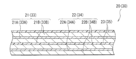
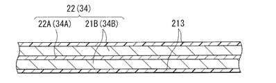
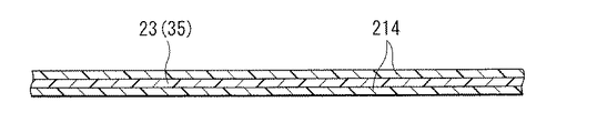
2−1−2.ラミネートフィルム型
2−2.リチウム金属二次電池
3.二次電池の用途
3−1.電池パック(単電池)
3−2.電池パック(組電池)
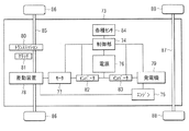
3−3.電動車両
3−4.電力貯蔵システム
3−5.電動工具
Hereinafter, an embodiment of the present technology will be described in detail with reference to the drawings. The order of explanation is as follows.
1. 1. Electrolytic solution for secondary battery Secondary battery 2-1. Lithium ion secondary battery 2-1-1. Cylindrical type 2-1-2. Laminate film type 2-2. Lithium metal secondary battery Applications of secondary battery 3-1. Battery pack (single cell)
3-2. Battery pack (assembled battery)
3-3. Electric vehicle 3-4. Electric power storage system 3-5. Electric tool
<1.二次電池用電解液>
まず、本技術の二次電池用電解液(以下、単に「電解液」という。)に関して説明する。<1. Electrolyte for secondary battery>
First, the secondary battery electrolyte solution of the present technology (hereinafter simply referred to as “electrolyte solution”) will be described.
[電解液の組成]
ここで説明する電解液は、例えば、二次電池などに用いられるものである。ただし、電解液が用いられる用途は、二次電池に限定されない。[Composition of electrolyte]
The electrolytic solution described here is used for, for example, a secondary battery. However, the use for which the electrolytic solution is used is not limited to the secondary battery.
この電解液は、スルホニルイミド型の構造を有する第1化合物と、アセトニトリル型の構造を有する第2化合物と、不飽和炭化水素基などの反応性基を有する第3化合物とを一緒に含んでいる。 The electrolytic solution includes a first compound having a sulfonylimide structure, a second compound having an acetonitrile structure, and a third compound having a reactive group such as an unsaturated hydrocarbon group. .
[第1化合物]
第1化合物は、式(1)で表される化合物のうちのいずれか1種類または2種類以上を含んでいる。この第1化合物は、カチオン(M+ )とアニオン([(Z1Y1)(Z2Y2)N]- )とを含む塩であるため、二次電池では電解質塩の一部として機能し得る。[First compound]
The 1st compound contains any 1 type in the compound represented by Formula (1), or 2 or more types. Since this first compound is a salt containing a cation (M + ) and an anion ([(Z1Y1) (Z2Y2) N] − ), it can function as a part of an electrolyte salt in a secondary battery.
M+ [(Z1Y1)(Z2Y2)N]- ・・・(1)
(Mは、金属元素である。Z1およびZ2のそれぞれは、フッ素基(−F)、1価の炭化水素基および1価のフッ素化炭化水素基のうちのいずれかであり、Z1およびZ2のうちの少なくとも一方は、フッ素基および1価のフッ素化炭化水素基のうちのいずれかである。Y1およびY2のそれぞれは、スルホニル基(−S(=O)2 −)およびカルボニル基(−C(=O)−)のうちのいずれかである。)M + [(Z1Y1) (Z2Y2) N] - (1)
(M is a metal element. Each of Z1 and Z2 is a fluorine group (-F), a monovalent hydrocarbon group, or a monovalent fluorinated hydrocarbon group. At least one of them is either a fluorine group or a monovalent fluorinated hydrocarbon group, and Y1 and Y2 are each a sulfonyl group (—S (═O) 2 —) and a carbonyl group (—C (= O)-)
Mの種類は、金属元素のうちのいずれかであれば、特に限定されないが、例えば、アルカリ金属元素およびアルカリ土類金属元素などである。 The type of M is not particularly limited as long as it is one of the metal elements, and examples thereof include alkali metal elements and alkaline earth metal elements.
中でも、Mの種類は、アルカリ金属元素であることが好ましい。高いエネルギー密度が得られるからである。このアルカリ金属元素は、例えば、リチウム(Li)、ナトリウム(Na)、カリウム(K)、ルビジウム(Rb)およびセシウム(Cs)などである。中でも、リチウムが好ましい。 Especially, it is preferable that the kind of M is an alkali metal element. This is because a high energy density can be obtained. Examples of the alkali metal element include lithium (Li), sodium (Na), potassium (K), rubidium (Rb), and cesium (Cs). Of these, lithium is preferable.
このアルカリ金属元素の種類は、電極反応物質の種類と同じであることが好ましい。より高いエネルギー密度が得られるからである。電極反応物質とは、電極反応に関わる物質であり、例えば、リチウム二次電池ではリチウムである。このため、リチウム二次電池に用いられるM(アルカリ金属元素)の種類は、リチウムであることが好ましい。 The kind of the alkali metal element is preferably the same as the kind of the electrode reactant. This is because a higher energy density can be obtained. The electrode reactant is a substance involved in the electrode reaction, for example, lithium in a lithium secondary battery. For this reason, it is preferable that the kind of M (alkali metal element) used for a lithium secondary battery is lithium.
Z1およびZ2のそれぞれの種類は、フッ素基、1価の炭化水素基および1価のフッ素化炭化水素基のうちのいずれかであれば、特に限定されない。Z1およびZ2は、同じ基でもよいし、異なる基でもよい。 Each type of Z1 and Z2 is not particularly limited as long as it is any one of a fluorine group, a monovalent hydrocarbon group, and a monovalent fluorinated hydrocarbon group. Z1 and Z2 may be the same group or different groups.
1価の炭化水素基とは、炭素(C)および水素(H)により構成される1価の基の総称であり、直鎖状でもよいし、1または2以上の側鎖を有する分岐状でもよい。この1価の飽和炭化水素基は、不飽和結合を含んでいない飽和炭化水素基でもよいし、1または2以上の不飽和結合を含んでいる不飽和炭化水素基でもよい。なお、不飽和結合とは、炭素間二重結合(>C=C<)および炭素間三重結合(−C≡C−)のうちの一方または双方である。 The monovalent hydrocarbon group is a general term for monovalent groups composed of carbon (C) and hydrogen (H), and may be linear or branched having one or more side chains. Good. The monovalent saturated hydrocarbon group may be a saturated hydrocarbon group not containing an unsaturated bond, or may be an unsaturated hydrocarbon group containing one or more unsaturated bonds. The unsaturated bond is one or both of a carbon-carbon double bond (> C═C <) and a carbon-carbon triple bond (—C≡C—).
1価の炭化水素基は、例えば、アルキル基、アルケニル基、アルキニル基、シクロアルキル基、アリール基およびそれらの2種類以上が1価となるように結合された基のうちのいずれかである。言い替えれば、1価の飽和炭化水素基は、例えば、アルキル基、シクロアルキル基およびそれらの2種類以上が1価となるように結合された基などである。1価の不飽和炭化水素基は、例えば、アルケニル基、アルキニル基、アリール基、それらの1種類以上を含む基およびそれらの2種類以上が1価となるように結合された基などである。 The monovalent hydrocarbon group is, for example, any one of an alkyl group, an alkenyl group, an alkynyl group, a cycloalkyl group, an aryl group, and a group in which two or more of them are monovalent. In other words, the monovalent saturated hydrocarbon group includes, for example, an alkyl group, a cycloalkyl group, and a group in which two or more of them are bonded so as to be monovalent. Examples of the monovalent unsaturated hydrocarbon group include an alkenyl group, an alkynyl group, an aryl group, a group containing one or more of them, and a group in which two or more of them are monovalent.
なお、1価の炭化水素基に関するそれらの2種類以上が結合された基は、例えば、アルキル基とアルケニル基とが結合された基、アルキル基とアルキニル基とが結合された基、アルケニル基とアルキニル基とが結合された基、アルキル基とシクロアルキル基とが結合された基、およびアルキル基とアリール基とが結合された基などである。 Examples of the group in which two or more types of monovalent hydrocarbon groups are bonded include a group in which an alkyl group and an alkenyl group are bonded, a group in which an alkyl group and an alkynyl group are bonded, and an alkenyl group. Examples include a group in which an alkynyl group is bonded, a group in which an alkyl group and a cycloalkyl group are bonded, and a group in which an alkyl group and an aryl group are bonded.
1価の飽和炭化水素基に関する2種類以上が結合された基は、例えば、アルキル基とシクロアルキル基とが1価となるように結合された基などである。 Examples of the group in which two or more kinds of monovalent saturated hydrocarbon groups are bonded include a group in which an alkyl group and a cycloalkyl group are bonded so as to be monovalent.
1価の不飽和炭化水素基に関する1種類以上を含む基は、例えば、アルキル基とアルケニル基とが1価となるように結合された基などである。また、2種類以上が結合された基は、例えば、アルケニル基とアルキニル基とが1価となるように結合された基などである。 Examples of the group containing one or more types related to the monovalent unsaturated hydrocarbon group include a group in which an alkyl group and an alkenyl group are bonded so as to be monovalent. The group in which two or more types are bonded is, for example, a group in which an alkenyl group and an alkynyl group are bonded so as to be monovalent.
アルキル基の具体例は、メチル基(−CH3 )、エチル基(−C2 H5 )、プロピル基(−C3 H7 )、n−ブチル基(−C4 H8 )およびt−ブチル基(−C(CH3 )2 −CH3 )などである。アルケニル基の具体例は、ビニル基(−CH=CH2 )およびアリル基(−CH2 −CH=CH2 )などである。アルキニル基の具体例は、エチニル基(−C≡CH)などである。シクロアルキル基の具体例は、シクロプロピル基、シクロブチル基、シクロペンチル基、シクロヘキシル基、シクロヘプチル基およびシクロオクチル基などである。アリール基の具体例は、フェニル基およびナフチル基などである。2種類以上が結合された基の具体例は、メチル基とエチニル基とが結合された基、ビニル基とエチニル基とが結合された基、メチル基とシクロプロピル基と結合された基およびメチル基とフェニル基とが結合された基などである。Specific examples of the alkyl group include a methyl group (—CH 3 ), an ethyl group (—C 2 H 5 ), a propyl group (—C 3 H 7 ), an n-butyl group (—C 4 H 8 ), and t-butyl. Group (—C (CH 3 ) 2 —CH 3 ) and the like. Specific examples of the alkenyl group include a vinyl group (—CH═CH 2 ) and an allyl group (—CH 2 —CH═CH 2 ). Specific examples of the alkynyl group include an ethynyl group (—C≡CH) and the like. Specific examples of the cycloalkyl group include a cyclopropyl group, a cyclobutyl group, a cyclopentyl group, a cyclohexyl group, a cycloheptyl group, and a cyclooctyl group. Specific examples of the aryl group include a phenyl group and a naphthyl group. Specific examples of the group in which two or more types are bonded include a group in which a methyl group and an ethynyl group are bonded, a group in which a vinyl group and an ethynyl group are bonded, a group in which a methyl group and a cyclopropyl group are bonded, and methyl And a group in which a group and a phenyl group are combined.
1価のフッ素化炭化水素基とは、上記した1価の炭化水素基のうちの1または2以上の水素基(−H)がフッ素基(−F)により置換された基である。 The monovalent fluorinated hydrocarbon group is a group in which one or two or more hydrogen groups (—H) in the above monovalent hydrocarbon groups are substituted with fluorine groups (—F).
この1価のフッ素化炭化水素基は、例えば、フッ素化アルキル基、フッ素化アルケニル基、フッ素化アルキニル基、フッ素化シクロアルキル基、フッ素化アリール基およびそれらの2種類以上が1価となるように結合された基などである。 Examples of the monovalent fluorinated hydrocarbon group include a fluorinated alkyl group, a fluorinated alkenyl group, a fluorinated alkynyl group, a fluorinated cycloalkyl group, a fluorinated aryl group, and two or more kinds thereof being monovalent. Or a group bonded to.
フッ素化アルキル基の具体例は、フルオロメチル基(−CH2 F)、ジフルオロメチル基(−CHF2 )、パーフルオロメチル基(−CF3 )、パーフルオロエチル基(−C2 F5 )、パーフルオロプロピル基(−C3 F7 )、n−パーフルオロブチル基(−C4 F8 )およびt−パーフルオロブチル基(−C(CF3 )2 −CF3 )などである。フッ素化アルケニル基の具体例は、パーフルオロビニル基(−CF=CF2 )およびパーフルオロアリル基(−CF2 −CF=CF2 )などである。フッ素化アルキニル基の具体例は、パーフルオロエチニル基(−F≡CF)などである。フッ素化シクロアルキル基の具体例は、パーフルオロシクロプロピル基、パーフルオロシクロブチル基、パーフルオロシクロペンチル基、パーフルオロシクロヘキシル基、パーフルオロシクロヘプチル基およびパーフルオロシクロオクチル基などである。フッ素化アリール基の具体例は、パーフルオロフェニル基およびパーフルオロナフチル基などである。Specific examples of the fluorinated alkyl group include a fluoromethyl group (—CH 2 F), a difluoromethyl group (—CHF 2 ), a perfluoromethyl group (—CF 3 ), a perfluoroethyl group (—C 2 F 5 ), A perfluoropropyl group (—C 3 F 7 ), an n-perfluorobutyl group (—C 4 F 8 ) and a t-perfluorobutyl group (—C (CF 3 ) 2 —CF 3 ). Specific examples of the fluorinated alkenyl group include a perfluorovinyl group (—CF═CF 2 ) and a perfluoroallyl group (—CF 2 —CF═CF 2 ). Specific examples of the fluorinated alkynyl group include a perfluoroethynyl group (—F≡CF). Specific examples of the fluorinated cycloalkyl group include a perfluorocyclopropyl group, a perfluorocyclobutyl group, a perfluorocyclopentyl group, a perfluorocyclohexyl group, a perfluorocycloheptyl group, and a perfluorocyclooctyl group. Specific examples of the fluorinated aryl group include a perfluorophenyl group and a perfluoronaphthyl group.
中でも、フッ素化アルキル基、フッ素化アルケニル基、フッ素化アルキニル基、フッ素化シクロアルキル基およびフッ素化アリール基のそれぞれは、パーフルオロ基であることが好ましく、パーフルオロアルキル基がより好ましい。容易に合成可能であると共に、後述する相乗作用が得られやすいからである。 Among these, each of the fluorinated alkyl group, the fluorinated alkenyl group, the fluorinated alkynyl group, the fluorinated cycloalkyl group, and the fluorinated aryl group is preferably a perfluoro group, and more preferably a perfluoroalkyl group. This is because it can be easily synthesized and a synergistic effect described later is easily obtained.
1価の炭化水素基および1価のフッ素化炭化水素基のそれぞれの炭素数は、特に限定されないが、中でも、極端に多すぎないことが好ましい。第1化合物の溶解性および相溶性などが向上するからである。具体的には、フッ素化アルキル基の炭素数は、1〜4であることが好ましい。フッ素化アルケニル基およびフッ素化アルキニル基のそれぞれの炭素数は、2〜4であることが好ましい。フッ素化シクロアルキル基およびフッ素化アリール基のそれぞれの炭素数は、6〜12であることが好ましい。 The number of carbon atoms in each of the monovalent hydrocarbon group and the monovalent fluorinated hydrocarbon group is not particularly limited. This is because the solubility and compatibility of the first compound are improved. Specifically, the fluorinated alkyl group preferably has 1 to 4 carbon atoms. The carbon number of each of the fluorinated alkenyl group and the fluorinated alkynyl group is preferably 2 to 4. Each of the fluorinated cycloalkyl group and the fluorinated aryl group preferably has 6 to 12 carbon atoms.
ただし、Z1およびZ2のうちの一方または双方は、フッ素基および1価のフッ素化炭化水素基のうちのいずれかである。容易に合成可能であると共に、後述する相乗作用が得られやすいからである。これに伴い、Z1およびZ2のうちの一方が1価の炭化水素基である場合、他方はフッ素基および1価のフッ素化炭化水素基のうちのいずれかである。すなわち、Z1およびZ2の双方は、1価の炭化水素基にならない。 However, one or both of Z1 and Z2 are either a fluorine group or a monovalent fluorinated hydrocarbon group. This is because it can be easily synthesized and a synergistic effect described later is easily obtained. Accordingly, when one of Z1 and Z2 is a monovalent hydrocarbon group, the other is either a fluorine group or a monovalent fluorinated hydrocarbon group. That is, both Z1 and Z2 do not become a monovalent hydrocarbon group.
Y1およびY2のそれぞれの種類は、スルホニル基およびカルボニル基のうちのいずれかであれば、特に限定されない。Y1およびY2は、同じ基でもよいし、異なる基でもよい。 Each kind of Y1 and Y2 is not particularly limited as long as it is either a sulfonyl group or a carbonyl group. Y1 and Y2 may be the same group or different groups.
第1化合物の具体例は、ビス(フルオロスルホニル)イミドリチウム(LiN(FSO2 )2 )、ビス(トリフルオロメチルスルホニル)イミドリチウム(LiN(CF3 SO2 )2 )、(フルオロスルホニル)(トリフルオロメチルスルホニル)イミドリチウム(LiN(FSO2 )(CF3 SO2 ))、(フルオロスルホニル)(ペンタフルオロエチルスルホニル)イミドリチウム(LiN(FSO2 )(C2 F5 SO2 ))、(フルオロスルホニル)(ノナフルオロブチルスルホニル)イミドリチウム(LiN(FSO2 )(C4 F9 SO2 ))、(フルオロスルホニル)(フェニルスルホニル)イミドリチウム(LiN(FSO2 )(C6 H5 SO2 ))、(フルオロスルホニル)(ペンタフルオロフェニルスルホニル)イミドリチウム(LiN(FSO2 )(C6 F5 SO2 ))および(フルオロスルホニル)(ビニルスルホニル)イミドリチウム(LiN(FSO2 )(C2 F3 SO2 ))などである。Specific examples of the first compound include bis (fluorosulfonyl) imide lithium (LiN (FSO 2 ) 2 ), bis (trifluoromethylsulfonyl) imide lithium (LiN (CF 3 SO 2 ) 2 ), (fluorosulfonyl) (tri Fluoromethylsulfonyl) imidolithium (LiN (FSO 2 ) (CF 3 SO 2 )), (fluorosulfonyl) (pentafluoroethylsulfonyl) imide lithium (LiN (FSO 2 ) (C 2 F 5 SO 2 )), (fluoro Sulfonyl) (nonafluorobutylsulfonyl) imidolithium (LiN (FSO 2 ) (C 4 F 9 SO 2 )), (fluorosulfonyl) (phenylsulfonyl) imidolithium (LiN (FSO 2 ) (C 6 H 5 SO 2 ) ), (Fluorosulfonyl) (pentafluorophenylsulfonyl) imidolithi And the like arm (LiN (FSO 2) (C 6 F 5 SO 2)) and (fluorosulfonyl) (vinylsulfonyl) imide lithium (LiN (FSO 2) (C 2 F 3 SO 2)).
後述する相乗作用を得るために、電解液中に第2化合物および第3化合物と一緒に含まれている第1化合物の含有量は、特定の範囲内でなければならない。具体的には、電解液中における第1化合物の含有量は、2.5mol/dm3 〜6mol/dm3 (2.5mol/l〜6mol/l)であり、好ましくは3mol/dm3 〜6mol/dm3 (3mol/l〜6mol/l)である。In order to obtain a synergistic effect described later, the content of the first compound contained in the electrolytic solution together with the second compound and the third compound must be within a specific range. Specifically, the content of the first compound in the electrolytic solution, a 2.5mol / dm 3 ~6mol / dm 3 (2.5mol / l~6mol / l), preferably 3mol / dm 3 ~6mol / Dm 3 (3 mol / l to 6 mol / l).
[第2化合物]
第2化合物は、式(2)および式(3)のそれぞれで表される化合物のうちのいずれか一方または双方を含んでいる。ただし、第2化合物は、式(2)に示した化合物のうちの2種類以上を含んでいてもよい。このことは、式(3)に示した化合物に関しても同様である。[Second compound]
The second compound contains either one or both of the compounds represented by formula (2) and formula (3). However, the 2nd compound may contain 2 or more types of the compounds shown in Formula (2). The same applies to the compound represented by the formula (3).
R1−CN ・・・(2)
(R1は、1価の炭化水素基である。)R1-CN (2)
(R1 is a monovalent hydrocarbon group.)
R2−X−CN ・・・(3)
(R2は、1価の炭化水素基である。Xは、1または2以上のエーテル結合(−O−)と1または2以上の2価の炭化水素基とが任意の順に結合された基である。)R2-X-CN (3)
(R2 is a monovalent hydrocarbon group. X is a group in which one or two or more ether bonds (—O—) and one or two or more divalent hydrocarbon groups are bonded in any order. is there.)
式(1)に示した化合物は、エーテル結合を含んでいないモノニトリル化合物(非酸素含有モノニトリル化合物)である。R1の種類は、1価の炭化水素基のうちのいずれかであれば、特に限定されない。この1価の炭化水素基に関する詳細は、上記した通りである。 The compound represented by the formula (1) is a mononitrile compound (non-oxygen-containing mononitrile compound) that does not include an ether bond. The type of R1 is not particularly limited as long as it is any of monovalent hydrocarbon groups. Details regarding the monovalent hydrocarbon group are as described above.
この非酸素含有モノニトリル化合物の具体例は、アセトニトリル(CH3 CN)、プロピオニトリル(C3 H7 CN)およびブチロニトリル(C4 H9 CN)などである。Specific examples of the non-oxygen-containing mononitrile compound include acetonitrile (CH 3 CN), propionitrile (C 3 H 7 CN), butyronitrile (C 4 H 9 CN), and the like.
式(2)に示した化合物は、エーテル結合を含んでいるモノニトリル化合物(酸素含有モノニトリル化合物)である。R2の種類は、1価の炭化水素基のうちのいずれかであれば、特に限定されない。この1価の炭化水素基に関する詳細は、上記した通りである。 The compound represented by the formula (2) is a mononitrile compound (oxygen-containing mononitrile compound) containing an ether bond. The type of R2 is not particularly limited as long as it is any of monovalent hydrocarbon groups. Details regarding the monovalent hydrocarbon group are as described above.
2価の炭化水素基とは、炭素および水素により構成される2価の基の総称であり、直鎖状でもよいし、1または2以上の側鎖を有する分岐状でもよい。この2価の炭化水素基は、例えば、アルキレン基、アルケニレン基、アルキニレン基、シクロアルキレン基、アリーレン基およびそれらの2種類以上が1価となるように結合された基などである。なお、2種類以上が結合された基は、例えば、アルキレン基とアルケニレン基とが結合された基、アルキル基とアルキニレン基とが結合された基、アルケニレン基とアルキニレン基とが結合された基、アルキレン基とシクロアルキレン基とが結合された基、およびアルキレン基とアリーレン基とが結合された基などである。 The divalent hydrocarbon group is a general term for divalent groups composed of carbon and hydrogen, and may be linear or branched having one or more side chains. Examples of the divalent hydrocarbon group include an alkylene group, an alkenylene group, an alkynylene group, a cycloalkylene group, an arylene group, and a group in which two or more of them are bonded so as to be monovalent. Note that the group in which two or more types are bonded includes, for example, a group in which an alkylene group and an alkenylene group are bonded, a group in which an alkyl group and an alkynylene group are bonded, a group in which an alkenylene group and an alkynylene group are bonded, A group in which an alkylene group and a cycloalkylene group are bonded, a group in which an alkylene group and an arylene group are bonded, and the like.
アルキレン基の具体例は、メチレン基(−CH2 −)、エチレン基(−C2 H4 −)、プロピレン基(−C3 H6 −)、n−ブチレン基(−C4 H8 −)およびt−ブチレン基(−C(CH3 )2 −CH2 −)などである。アルケニレン基の具体例は、ビニレン基(−CH=CH−)およびアリレン基(−CH2 −CH=CH−)などである。アルキニレン基の具体例は、エチニレン基(−C≡C−)などである。シクロアルキレン基の具体例は、シクロプロピレン基、シクロブチレン基、シクロペンチレン基、シクロヘキシレン基、シクロヘプチレン基およびシクロオクチレン基などである。アリーレン基の具体例は、フェニレン基およびナフチレン基などである。2種類以上が結合された基の具体例は、メチレン基とエチニレン基とが結合された基、ビニレン基とエチニレン基とが結合された基、メチレン基とシクロプロピレン基と結合された基、およびメチレン基とフェニレン基とが結合された基などである。Specific examples of the alkylene group include a methylene group (—CH 2 —), an ethylene group (—C 2 H 4 —), a propylene group (—C 3 H 6 —), and an n-butylene group (—C 4 H 8 —). And t-butylene group (—C (CH 3 ) 2 —CH 2 —) and the like. Specific examples of the alkenylene group include a vinylene group (—CH═CH—) and an arylene group (—CH 2 —CH═CH—). Specific examples of the alkynylene group include an ethynylene group (—C≡C—) and the like. Specific examples of the cycloalkylene group include a cyclopropylene group, a cyclobutylene group, a cyclopentylene group, a cyclohexylene group, a cycloheptylene group, and a cyclooctylene group. Specific examples of the arylene group include a phenylene group and a naphthylene group. Specific examples of the group in which two or more types are bonded include a group in which a methylene group and an ethynylene group are bonded, a group in which a vinylene group and an ethynylene group are bonded, a group in which a methylene group and a cyclopropylene group are bonded, and And a group in which a methylene group and a phenylene group are bonded.
2価の炭化水素基の炭素数は、特に限定されないが、中でも、極端に多すぎないことが好ましい。第2化合物の溶解性および相溶性などが向上するからである。具体的には、アルキレン基の炭素数は、1〜4であることが好ましい。アルケニレン基およびアルキニレン基のそれぞれの炭素数は、2〜4であることが好ましい。シクロアルキレン基およびアリーレン基のそれぞれの炭素数は、6〜12であることが好ましい。 The number of carbon atoms of the divalent hydrocarbon group is not particularly limited. This is because the solubility and compatibility of the second compound are improved. Specifically, the alkylene group preferably has 1 to 4 carbon atoms. Each of the alkenylene group and the alkynylene group preferably has 2 to 4 carbon atoms. The carbon number of each of the cycloalkylene group and the arylene group is preferably 6-12.
Xの種類は、1または2以上のエーテル結合と1または2以上の2価の炭化水素基とが任意の順に結合された基であれば、特に限定されない。すなわち、X中に含まれるエーテル結合の数は、1でもよいし、2以上でもよい。同様に、X中に含まれる2価の炭化水素基の数は、1でもよいし、2以上でもよい。この2価の炭化水素基の数が2以上である場合、その2以上の2価の炭化水素基は、同じ基でもよいし、異なる基でもよい。もちろん、2以上の2価の炭化水素基のうちの一部が同じ基でもよい。エーテル結合と2価の炭化水素基とが結合される順序は任意でよいため、エーテル結合同士が結合されてもよいし、2価の炭化水素基同士が結合されてもよいし、エーテル結合と2価の炭化水素基とが結合されてもよい。 The type of X is not particularly limited as long as it is a group in which one or more ether bonds and one or two or more divalent hydrocarbon groups are bonded in any order. That is, the number of ether bonds contained in X may be 1 or 2 or more. Similarly, the number of divalent hydrocarbon groups contained in X may be 1 or 2 or more. When the number of the divalent hydrocarbon groups is 2 or more, the two or more divalent hydrocarbon groups may be the same group or different groups. Of course, a part of two or more divalent hydrocarbon groups may be the same group. Since the order in which the ether bond and the divalent hydrocarbon group are bonded may be arbitrary, the ether bonds may be bonded to each other, the divalent hydrocarbon groups may be bonded to each other, A divalent hydrocarbon group may be combined.
中でも、Xは、−O−Y−(Yは、2価の炭化水素基である。)で表される基であることが好ましい。容易に合成可能であると共に、後述する相乗作用が得られやすいからである。この2価の炭化水素基に関する詳細は、上記した通りである。ただし、ここで説明したX(−O−Y−)では、エーテル結合(−O−)がR2に結合されると共に、Yがシアノ基(−CN)に結合される。 Among these, X is preferably a group represented by —O—Y— (Y is a divalent hydrocarbon group). This is because it can be easily synthesized and a synergistic effect described later is easily obtained. Details regarding the divalent hydrocarbon group are as described above. However, in X (—O—Y—) described here, an ether bond (—O—) is bonded to R 2 and Y is bonded to a cyano group (—CN).
Xの具体例は、−O−CH2 −、−CH2 −O−、−O−CH2 −O−および−O−C2 H5 −などである。Specific examples of X include —O—CH 2 —, —CH 2 —O—, —O—CH 2 —O—, —O—C 2 H 5 — and the like.
この酸素含有モノニトリル化合物の具体例は、メトキシアセトニトリル(CH3 −O−CH2 −CN)、エトキシアセトニトリル(C2 H5 −O−CH2 −CN)およびプロポキシアセトニトリル(C3 H7 −O−CH2 −CN)などである。Specific examples of the oxygen-containing mononitrile compound include methoxyacetonitrile (CH 3 —O—CH 2 —CN), ethoxyacetonitrile (C 2 H 5 —O—CH 2 —CN), and propoxyacetonitrile (C 3 H 7 —O). -CH 2 -CN), and the like.
電解液中における第2化合物の含有量は、特に限定されないが、例えば、20質量%〜100質量%であることが好ましい。後述する相乗作用が得られやすいからである。 Although content of the 2nd compound in electrolyte solution is not specifically limited, For example, it is preferable that they are 20 mass%-100 mass%. This is because a synergistic effect described later is easily obtained.
なお、第2化合物が非酸素含有モノニトリル化合物および酸素含有モノニトリル化合物の双方を含む場合には、上記した第2化合物の含有量は、非酸素含有モノニトリル化合物の含有量と酸素含有モノニトリル化合物の含有量との総和である。このように含有量が総和を意味することは、以降においても同様である。 When the second compound contains both a non-oxygen-containing mononitrile compound and an oxygen-containing mononitrile compound, the content of the second compound described above is the content of the non-oxygen-containing mononitrile compound and the oxygen-containing mononitrile. It is the sum total with the content of the compound. This means that the content means the sum in the following.
[第3化合物]
第3化合物は、不飽和環状炭酸エステル、ハロゲン化環状炭酸エステルおよびポリニトリル化合物のうちのいずれか1種類または2種類以上を含んでいる。ただし、第3化合物は、不飽和環状炭酸エステルのうちの2種類以上を含んでいてもよい。このように2種類以上を含んでいてもよいことは、ハロゲン化環状炭酸エステルおよびポリニトリル化合物のそれぞれに関しても同様である。[Third compound]
The third compound contains one or more of unsaturated cyclic carbonate, halogenated cyclic carbonate and polynitrile compound. However, the third compound may contain two or more types of unsaturated cyclic carbonates. The fact that two or more kinds may be contained in this way is the same for each of the halogenated cyclic carbonate and the polynitrile compound.
不飽和環状炭酸エステルは、式(4)〜式(6)のそれぞれに示した化合物のうちのいずれか1種類または2種類以上を含んでいる。この不飽和環状炭酸エステルとは、1または2以上の不飽和結合(炭素間二重結合)を含む環状炭酸エステルである。 The unsaturated cyclic ester carbonate contains any one or two or more of the compounds shown in the formulas (4) to (6). This unsaturated cyclic carbonate is a cyclic carbonate containing one or more unsaturated bonds (carbon-carbon double bonds).
式(4)に示した化合物は、炭酸ビニレン系化合物である。R3およびR4のそれぞれの種類は、水素基および1価の炭化水素基のうちのいずれかであれば、特に限定されない。この1価の炭化水素基に関する詳細は、上記した通りである。R3およびR4は、同じ基でもよいし、異なる基でもよい。 The compound represented by the formula (4) is a vinylene carbonate compound. Each type of R3 and R4 is not particularly limited as long as it is any one of a hydrogen group and a monovalent hydrocarbon group. Details regarding the monovalent hydrocarbon group are as described above. R3 and R4 may be the same group or different groups.
炭酸ビニレン系化合物の具体例は、炭酸ビニレン(1,3−ジオキソール−2−オン)、炭酸メチルビニレン(4−メチル−1,3−ジオキソール−2−オン)、炭酸エチルビニレン(4−エチル−1,3−ジオキソール−2−オン)、4,5−ジメチル−1,3−ジオキソール−2−オン、4,5−ジエチル−1,3−ジオキソール−2−オン、4−フルオロ−1,3−ジオキソール−2−オン、および4−トリフルオロメチル−1,3−ジオキソール−2−オンなどである。中でも、炭酸ビニレンが好ましい。容易に合成可能だからである。 Specific examples of vinylene carbonate compounds include vinylene carbonate (1,3-dioxol-2-one), methyl vinylene carbonate (4-methyl-1,3-dioxol-2-one), ethyl vinylene carbonate (4-ethyl- 1,3-dioxol-2-one), 4,5-dimethyl-1,3-dioxol-2-one, 4,5-diethyl-1,3-dioxol-2-one, 4-fluoro-1,3 -Dioxol-2-one, 4-trifluoromethyl-1,3-dioxol-2-one, and the like. Among these, vinylene carbonate is preferable. This is because it can be easily synthesized.
式(5)に示した化合物は、炭酸ビニルエチレン系化合物である。R5〜R8のそれぞれの種類は、水素基、1価の飽和炭化水素基および1価の不飽和炭化水素基のうちのいずれかであれば、特に限定されない。1価の飽和炭化水素基および1価の不飽和炭化水素基のそれぞれに関する詳細は、上記した通りである。ただし、R5〜R8のうちの1または2以上は、1価の不飽和炭化水素基である。炭酸ビニルエチレン系化合物は、1または2以上の不飽和結合(炭素間二重結合)を含んでいなければならないからである。R5〜R8は、同じ基でもよいし、異なる基でもよい。もちろん、R5〜R8のうちの一部が同じ基でもよい。 The compound represented by the formula (5) is a vinyl ethylene carbonate compound. Each type of R5 to R8 is not particularly limited as long as it is any one of a hydrogen group, a monovalent saturated hydrocarbon group, and a monovalent unsaturated hydrocarbon group. The details regarding each of the monovalent saturated hydrocarbon group and the monovalent unsaturated hydrocarbon group are as described above. However, 1 or 2 or more of R5 to R8 is a monovalent unsaturated hydrocarbon group. This is because the vinyl carbonate-based compound must contain one or more unsaturated bonds (carbon-carbon double bonds). R5 to R8 may be the same group or different groups. Of course, a part of R5 to R8 may be the same group.
炭酸ビニルエチレン系化合物の具体例は、炭酸ビニルエチレン(4−ビニル−1,3−ジオキソラン−2−オン)、4−メチル−4−ビニル−1,3−ジオキソラン−2−オン、4−エチル−4−ビニル−1,3−ジオキソラン−2−オン、4−n−プロピル−4−ビニル−1,3−ジオキソラン−2−オン、5−メチル−4−ビニル−1,3−ジオキソラン−2−オン、4,4−ジビニル−1,3−ジオキソラン−2−オン、および4,5−ジビニル−1,3−ジオキソラン−2−オンなどである。中でも、炭酸ビニルエチレンが好ましい。容易に合成可能だからである。 Specific examples of the vinyl carbonate ethylene compound include vinyl ethylene carbonate (4-vinyl-1,3-dioxolan-2-one), 4-methyl-4-vinyl-1,3-dioxolan-2-one, and 4-ethyl. -4-vinyl-1,3-dioxolan-2-one, 4-n-propyl-4-vinyl-1,3-dioxolan-2-one, 5-methyl-4-vinyl-1,3-dioxolane-2 -One, 4,4-divinyl-1,3-dioxolan-2-one, 4,5-divinyl-1,3-dioxolan-2-one, and the like. Of these, vinyl ethylene carbonate is preferred. This is because it can be easily synthesized.
式(6)に示した化合物は、炭酸メチレンエチレン系化合物である。R9の種類は、>CR10R11で表される基であれば、特に限定されない。1価の炭化水素基に関する詳細は、上記した通りである。R10およびR11は、同じ基でもよいし、異なる基でもよい。 The compound represented by the formula (6) is a methylene ethylene carbonate compound. The type of R9 is not particularly limited as long as it is a group represented by> CR10R11. Details regarding the monovalent hydrocarbon group are as described above. R10 and R11 may be the same group or different groups.
炭酸メチレンエチレン系化合物の具体例は、炭酸メチレンエチレン(4−メチレン−1 ,3−ジオキソラン−2−オン)、4,4−ジメチル−5−メチレン−1,3−ジオキソラン−2−オン、および4,4−ジエチル−5−メチレン−1,3−ジオキソラン−2−オンなどである。 Specific examples of methylene ethylene carbonate compounds include methylene ethylene carbonate (4-methylene-1,3-dioxolan-2-one), 4,4-dimethyl-5-methylene-1,3-dioxolan-2-one, and 4,4-diethyl-5-methylene-1,3-dioxolan-2-one and the like.
この他、不飽和環状炭酸エステルは、2つのメチレン基を含む化合物でもよいし、ベンゼン環を含む炭酸カテコール(カテコールカーボネート)などでもよい。2つのメチレン基を含む化合物とは、式(6)において、>C=R9の代わりに>C=CH2 を含むと共に>CH2の代わりに>C=CH2 を含む化合物である。In addition, the unsaturated cyclic carbonate may be a compound containing two methylene groups, or catechol carbonate (catechol carbonate) containing a benzene ring. The compounds containing two methylene groups in formula (6) is>> compounds containing C = CH 2 in place of CH2 with containing> C = CH 2 instead of> C = R9.
電解液中における不飽和環状炭酸エステルの含有量は、特に限定されないが、例えば、不飽和環状炭酸エステルを除いた全体の合計に対して0.01質量%〜20質量%であることが好ましい。 Although content of unsaturated cyclic carbonate in electrolyte solution is not specifically limited, For example, it is preferable that it is 0.01 mass%-20 mass% with respect to the total of the whole except unsaturated cyclic carbonate.
ハロゲン化環状炭酸エステルは、式(7)および式(8)のそれぞれに示した化合物のうちのいずれか1種類または2種類以上を含んでいる。このハロゲン化炭酸エステルとは、1または2以上のハロゲン基を有する炭酸エステルである。 The halogenated cyclic carbonate contains any one or more of the compounds represented by formula (7) and formula (8). The halogenated carbonate is a carbonate having one or more halogen groups.
式(7)に示した化合物は、ハロゲン化環状炭酸エステルである。R12〜R15のそれぞれの種類は、水素基、ハロゲン基、1価の炭化水素基および1価のハロゲン化炭化水素基のうちのいずれかであれば、特に限定されない。1価の炭化水素基に関する詳細は、上記した通りである。ただし、R12〜R15のうちの1または2以上は、ハロゲン基および1価のハロゲン化炭化水素基のうちのいずれかである。ハロゲン化環状炭酸エステルは、1または2以上のハロゲン基を含んでいなければならないからである。R12〜R15は、同じ基でもよいし、異なる基でもよい。もちろん、R12〜R15のうちの一部が同じ基でもよい。 The compound represented by formula (7) is a halogenated cyclic carbonate. Each type of R12 to R15 is not particularly limited as long as it is any one of a hydrogen group, a halogen group, a monovalent hydrocarbon group, and a monovalent halogenated hydrocarbon group. Details regarding the monovalent hydrocarbon group are as described above. However, one or more of R12 to R15 are either a halogen group or a monovalent halogenated hydrocarbon group. This is because the halogenated cyclic carbonate must contain one or more halogen groups. R12 to R15 may be the same group or different groups. Of course, some of R12 to R15 may be the same group.
1価のハロゲン化炭化水素基とは、上記した1価の炭化水素基のうちの1または2以上の水素基がハロゲン基により置換された基である。このハロゲン基の種類は、特に限定されないが、例えば、フッ素基、塩素基(−Cl)、臭素基(−Br)およびヨウ素基(−I)などのうちのいずれかである。中でも、フッ素基が好ましい。容易に合成可能であると共に、後述する相乗作用が得られやすいである。なお、ハロゲン基の数は、1よりも2が好ましく、さらに3以上でもよい。より高い効果が得られるからである。 The monovalent halogenated hydrocarbon group is a group in which one or two or more hydrogen groups among the above-described monovalent hydrocarbon groups are substituted with a halogen group. Although the kind of this halogen group is not specifically limited, For example, they are either a fluorine group, a chlorine group (-Cl), a bromine group (-Br), an iodine group (-I), etc. Among these, a fluorine group is preferable. It can be easily synthesized, and a synergistic effect described later is easily obtained. The number of halogen groups is preferably 2 rather than 1, and may be 3 or more. This is because a higher effect can be obtained.
この1価のハロゲン化炭化水素基は、例えば、ハロゲン化アルキル基、ハロゲン化アルケニル基、ハロゲン化アルキニル基、ハロゲン化シクロアルキル基、ハロゲン化アリール基およびそれらの2種類以上が1価となるように結合された基などである。 The monovalent halogenated hydrocarbon group includes, for example, a halogenated alkyl group, a halogenated alkenyl group, a halogenated alkynyl group, a halogenated cycloalkyl group, a halogenated aryl group, and two or more of them are monovalent. Or a group bonded to.
ハロゲン化アルキル基のうち、フッ素化アルキル基、フッ素化アルケニル基、フッ素化アルキニル基、フッ素化シクロアルキル基およびフッ素化アリール基の具体例は、上記した通りである。塩素化アルキル基、臭素化アルキル基およびヨウ素化アルキル基のそれぞれの具体例は、上記したフッ素化アルキル基の具体例のうちのフッ素基を塩素基、臭素基およびヨウ素基のそれぞれに変更した化合物である。このようにフッ素基を塩素基、臭素基およびヨウ素基のそれぞれに変更することは、塩素化アルケニル基、塩素化アルキニル基、塩素化シクロアルキル基、塩素化アリール基、臭素化アルケニル基、臭素化アルキニル基、臭素化シクロアルキル基、臭素化アリール基、ヨウ素化アルケニル基、ヨウ素化アルキニル基、ヨウ素化シクロアルキル基およびヨウ素化アリール基に関しても同様である。 Among the halogenated alkyl groups, specific examples of the fluorinated alkyl group, the fluorinated alkenyl group, the fluorinated alkynyl group, the fluorinated cycloalkyl group, and the fluorinated aryl group are as described above. Specific examples of the chlorinated alkyl group, brominated alkyl group and iodinated alkyl group are compounds in which the fluorine group in the above specific examples of the fluorinated alkyl group is changed to a chlorine group, a bromine group and an iodine group, respectively. It is. Changing the fluorine group to a chlorine group, a bromine group, and an iodine group in this way is a chlorinated alkenyl group, a chlorinated alkynyl group, a chlorinated cycloalkyl group, a chlorinated aryl group, a brominated alkenyl group, a brominated group. The same applies to alkynyl groups, brominated cycloalkyl groups, brominated aryl groups, iodinated alkenyl groups, iodinated alkynyl groups, iodinated cycloalkyl groups, and iodinated aryl groups.
ハロゲン化環状炭酸エステルの具体例は、4−フルオロ−1,3−ジオキソラン−2−オン、4−クロロ−1,3−ジオキソラン−2−オン、4,5−ジフルオロ−1,3−ジオキソラン−2−オン、テトラフルオロ−1,3−ジオキソラン−2−オン、4−クロロ−5−フルオロ−1,3−ジオキソラン−2−オン、の4,5−ジクロロ−1,3−オキソラン−2−オン、テトラクロロ−1,3−ジオキソラン−2−オン、4,5−ビストリフルオロメチル−1,3−ジオキソラン−2−オン、4−トリフルオロメチル−1,3−ジオキソラン−2−オン、4,5−ジフルオロ−4,5−ジメチル−1,3−ジオキソラン−2−オン、4,4−ジフルオロ−5−メチル−1,3−ジオキソラン−2−オン、4−エチル−5,5−ジフルオロ−1,3−ジオキソラン−2−オン、4−フルオロ−5−トリフルオロメチル−1,3−ジオキソラン−2−オン、4−メチル−5−トリフルオロメチル−1,3−ジオキソラン−2−オン、4−フルオロ−4,5−ジメチル−1,3−ジオキソラン−2−オン、5−(1,1−ジフルオロエチル)−4,4−ジフルオロ−1,3−ジオキソラン−2−オン、4,5−ジクロロ−4,5−ジメチル−1,3−ジオキソラン−2−オン、4−エチル−5−フルオロ−1,3−ジオキソラン−2−オン、4−エチル−4,5−ジフルオロ−1,3−ジオキソラン−2−オン、4−エチル−4,5,5−トリフルオロ−1,3−ジオキソラン−2−オンおよび4−フルオロ−4−メチル−1,3−ジオキソラン−2−オンなどである。なお、ここで説明するハロゲン化環状炭酸エステルの具体例には、異性体(シス異性体およびトランス異性体)が含まれる。 Specific examples of the halogenated cyclic carbonate include 4-fluoro-1,3-dioxolan-2-one, 4-chloro-1,3-dioxolan-2-one, 4,5-difluoro-1,3-dioxolane- 2-one, tetrafluoro-1,3-dioxolan-2-one, 4-chloro-5-fluoro-1,3-dioxolan-2-one, 4,5-dichloro-1,3-oxolane-2-one ON, tetrachloro-1,3-dioxolan-2-one, 4,5-bistrifluoromethyl-1,3-dioxolan-2-one, 4-trifluoromethyl-1,3-dioxolan-2-one, 4 , 5-difluoro-4,5-dimethyl-1,3-dioxolan-2-one, 4,4-difluoro-5-methyl-1,3-dioxolan-2-one, 4-ethyl-5,5-difluoro 1,3-dioxolan-2-one, 4-fluoro-5-trifluoromethyl-1,3-dioxolan-2-one, 4-methyl-5-trifluoromethyl-1,3-dioxolan-2-one, 4-fluoro-4,5-dimethyl-1,3-dioxolan-2-one, 5- (1,1-difluoroethyl) -4,4-difluoro-1,3-dioxolan-2-one, 4,5 -Dichloro-4,5-dimethyl-1,3-dioxolan-2-one, 4-ethyl-5-fluoro-1,3-dioxolan-2-one, 4-ethyl-4,5-difluoro-1,3 -Dioxolan-2-one, 4-ethyl-4,5,5-trifluoro-1,3-dioxolan-2-one and 4-fluoro-4-methyl-1,3-dioxolan-2-one . Specific examples of the halogenated cyclic carbonate described here include isomers (cis isomer and trans isomer).
式(8)に示した化合物は、ハロゲン化鎖状炭酸エステルである。R16〜R21のそれぞれの種類は、水素基、ハロゲン基、1価の炭化水素基および1価のハロゲン化炭化水素基のうちのいずれかであれば、特に限定されない。1価の炭化水素基および1価のハロゲン化炭化水素基のそれぞれに関する詳細は、上記した通りである。ただし、上記したハロゲン化環状炭酸エステルと同様の理由により、R16〜R21のうちの1または2以上は、ハロゲン基および1価のハロゲン化炭化水素基のうちのいずれかである。R16〜R21は、同じ基でもよいし、異なる基でもよい。もちろん、R16〜R21のうちの一部が同じ基でもよい。 The compound represented by the formula (8) is a halogenated chain carbonate. Each type of R16 to R21 is not particularly limited as long as it is any one of a hydrogen group, a halogen group, a monovalent hydrocarbon group, and a monovalent halogenated hydrocarbon group. The details regarding each of the monovalent hydrocarbon group and the monovalent halogenated hydrocarbon group are as described above. However, for the same reason as the above-mentioned halogenated cyclic carbonate, one or more of R16 to R21 are either a halogen group or a monovalent halogenated hydrocarbon group. R16 to R21 may be the same group or different groups. Of course, some of R16 to R21 may be the same group.
ハロゲン化鎖状炭酸エステルの具体例は、炭酸フルオロメチルメチル、炭酸ビス(フルオロメチル)および炭酸ジフルオロメチルメチルなどである。 Specific examples of the halogenated chain carbonate ester include fluoromethyl methyl carbonate, bis (fluoromethyl) carbonate and difluoromethyl methyl carbonate.
電解液中におけるハロゲン化環状炭酸エステルの含有量は、特に限定されないが、例えば、ハロゲン化環状炭酸エステルを除いた全体の合計に対して0.01質量%〜20質量%であることが好ましい。 Although content of halogenated cyclic carbonate in electrolyte solution is not specifically limited, For example, it is preferable that it is 0.01 mass%-20 mass% with respect to the total of the whole except halogenated cyclic carbonate.
ポリニトリル化合物は、式(9)に示した化合物のうちのいずれか1種類または2種類以上を含んでいる。このポリニトリル化合物は、2以上のニトリル基を含む化合物であり、上記した第2化合物は、ここで説明するポリニトリル化合物に含まれない。第2化合物は、2以上のニトリル基を含んでいないからである。 The polynitrile compound contains any one kind or two or more kinds of compounds represented by the formula (9). This polynitrile compound is a compound containing two or more nitrile groups, and the above-described second compound is not included in the polynitrile compound described here. This is because the second compound does not contain two or more nitrile groups.
R22−(CN)n ・・・(9)
(R22は、n価の炭化水素基である。nは、2以上の整数である。)R22- (CN) n (9)
(R22 is an n-valent hydrocarbon group. N is an integer of 2 or more.)
R22の種類は、n価の炭化水素基であれば、特に限定されない。一例を挙げると、R22の炭素数が1である場合には、2価の炭化水素基は−CH2 −、3価の炭化水素基は>CH−などである。同様に、R22の炭素数が2である場合には、2価の炭化水素基は−CH2 −CH2 −、3価の炭化水素基は>CH−CH2 −などである。The type of R22 is not particularly limited as long as it is an n-valent hydrocarbon group. As an example, when R22 has 1 carbon, the divalent hydrocarbon group is —CH 2 —, the trivalent hydrocarbon group is> CH—, and the like. Similarly, when R22 has 2 carbon atoms, the divalent hydrocarbon group is —CH 2 —CH 2 —, the trivalent hydrocarbon group is> CH—CH 2 — and the like.
中でも、R22は、2価の炭化水素基であることが好ましい。シアノ基(−CN)の数が2になるため、後述する相乗作用が得られやすいからである。この2価の炭化水素基に関する詳細は、上記した通りである。 Among these, R22 is preferably a divalent hydrocarbon group. This is because the number of cyano groups (—CN) is 2, and a synergistic effect described later is easily obtained. Details regarding the divalent hydrocarbon group are as described above.
ポリニトリル化合物の具体例は、マロノニトリル、スクシノニトリル、グルタロニトリル、アジポニトリル、ピメロニトリル、スベロニトリル、アゼラニトリル、セバコニトリル、ウンデカンジニトリル、ドデカンジニトリル、フタロニトリルおよびテトラシアノキノジメタンなどである。 Specific examples of the polynitrile compound include malononitrile, succinonitrile, glutaronitrile, adiponitrile, pimeonitrile, suberonitrile, azeronitrile, sebacononitrile, undecandinitrile, dodecandinitrile, phthalonitrile and tetracyanoquinodimethane.
電解液中におけるポリニトリル化合物の含有量は、特に限定されないが、例えば、ポリニトリル化合物を除いた全体の合計に対して0.01質量%〜10質量%であることが好ましい。 Although content of the polynitrile compound in electrolyte solution is not specifically limited, For example, it is preferable that it is 0.01 mass%-10 mass% with respect to the total of the whole except a polynitrile compound.
[電解液の組成の理由]
ここで、電解液が上記した組成を有しているのは、以下の利点が得られるからである。電解液が第1化合物、第2化合物および第3化合物を一緒に含んでいると共に、その電解液中における第1化合物の含有量が上記した範囲内であると、第1化合物と第2化合物と第3化合物との相乗作用により、電解液の化学的安定性が特異的に向上する。特に、ここで説明する特異的な相乗作用が得られるかどうかは、第1化合物の含有量に依存する。このため、特異的な相乗作用は、第1化合物の含有量が上記した範囲内である場合においてだけ得られるが、その第1化合物の含有量が上記した範囲外である場合には得られない。これにより、充放電時における電解液の分解反応が抑制されるため、充放電を繰り返しても放電容量が減少しにくくなる。よって、二次電池の電池特性が向上する。[Reason for composition of electrolyte]
Here, the reason why the electrolytic solution has the above-described composition is that the following advantages are obtained. When the electrolytic solution contains the first compound, the second compound, and the third compound together, and the content of the first compound in the electrolytic solution is within the above-described range, the first compound, the second compound, Due to the synergistic action with the third compound, the chemical stability of the electrolytic solution is specifically improved. In particular, whether or not the specific synergistic effect described here is obtained depends on the content of the first compound. Therefore, a specific synergistic effect is obtained only when the content of the first compound is within the above-mentioned range, but is not obtained when the content of the first compound is outside the above-mentioned range. . Thereby, since the decomposition reaction of the electrolytic solution at the time of charging / discharging is suppressed, even if charging / discharging is repeated, the discharge capacity is hardly reduced. Therefore, the battery characteristics of the secondary battery are improved.
[他材料]
なお、電解液は、上記した第1化合物、第2化合物および第3化合物に加えて、他材料のうちのいずれか1種類または2種類以上を含んでいてもよい。[Other materials]
In addition, in addition to the first compound, the second compound, and the third compound, the electrolytic solution may include any one type or two or more types of other materials.
他材料は、例えば、スルホン酸エステル、酸無水物、環状カルボン酸エステル(ラクトン)、ジアルキルスルホキシド、鎖状ジ炭酸エステル、芳香族炭酸エステル、環状炭酸エステル、鎖状モノ炭酸エステル、鎖状カルボン酸エステル、リン酸エステル、モノフルオロリン酸リチウム(Li2 PO3 F)およびジフルオロリン酸リチウム(LiPO2 F2 )のうちのいずれか1種類または2種類以上である。Other materials include, for example, sulfonic acid esters, acid anhydrides, cyclic carboxylic acid esters (lactones), dialkyl sulfoxides, chain dicarbonates, aromatic carbonates, cyclic carbonates, chain monocarbonates, chain carboxylic acids One or more of ester, phosphate ester, lithium monofluorophosphate (Li 2 PO 3 F) and lithium difluorophosphate (LiPO 2 F 2 ).
スルホン酸エステルは、例えば、モノスルホン酸エステルおよびジスルホン酸エステルなどである。 Examples of the sulfonate ester include a monosulfonate ester and a disulfonate ester.
モノスルホン酸エステルは、環状モノスルホン酸エステルでもよいし、鎖状モノスルホン酸エステルでもよい。環状モノスルホン酸エステルの具体例は、プロパンスルトンおよびプロペンスルトンなどのスルトンである。鎖状モノスルホン酸エステルの具体例は、環状モノスルホン酸エステルが途中で切断された構造を有する化合物である。一例を挙げると、プロパンスルトンが途中で切断された化合物は、CH3 −CH2 −CH2 −SO3 −CH3 などである。この−SO3 −(−S(=O)2 −O−)の向きは、特に限定されない。すなわち、上記したCH3 −CH2 −CH2 −SO3 −CH3 は、CH3 −CH2 −CH2 −S(=O)2 −O−CH3 でもよいし、CH3 −CH2 −CH2 −O−S(=O)2 −CH3 でもよい。The monosulfonic acid ester may be a cyclic monosulfonic acid ester or a chain monosulfonic acid ester. Specific examples of cyclic monosulfonic acid esters are sultone such as propane sultone and propene sultone. A specific example of the chain monosulfonic acid ester is a compound having a structure in which a cyclic monosulfonic acid ester is cleaved on the way. For example, a compound in which propane sultone is cleaved in the middle is CH 3 —CH 2 —CH 2 —SO 3 —CH 3 or the like. The direction of this —SO 3 — (— S (═O) 2 —O—) is not particularly limited. That is, the above CH 3 —CH 2 —CH 2 —SO 3 —CH 3 may be CH 3 —CH 2 —CH 2 —S (═O) 2 —O—CH 3 , or CH 3 —CH 2 —. CH 2 —O—S (═O) 2 —CH 3 may also be used.
ジスルホン酸エステルは、環状ジスルホン酸エステルでもよいし、鎖状ジスルホン酸エステルでもよい。環状ジスルホン酸エステルの具体例は、式(16−1)〜式(16−3)のそれぞれで表される化合物などである。鎖状ジスルホン酸エステルは、環状ジスルホン酸エステルが途中で切断された化合物である。一例を挙げると、式(16−2)に示した化合物が途中で切断された化合物は、CH3 −SO3 −CH2 −CH2 −SO3 −CH3 などである。2つの−SO3 −(−S(=O)2 −O−)の向きは、特に限定されない。すなわち、上記したCH3 −SO3 −CH2 −CH2 −SO3 −CH3 は、CH3 −S(=O)2 −O−CH2 −CH2 −S(=O)2 −O−CH3 でもよいし、CH3 −O−S(=O)2 −CH2 −CH2 −S(=O)2 −O−CH3 でもよいし、CH3 −S(=O)2 −O−CH2 −CH2 −O−S(=O)2 −CH3 でもよい。The disulfonic acid ester may be a cyclic disulfonic acid ester or a chain disulfonic acid ester. Specific examples of the cyclic disulfonic acid ester include compounds represented by formulas (16-1) to (16-3). A chain disulfonic acid ester is a compound in which a cyclic disulfonic acid ester is cleaved on the way. As an example, a compound obtained by cleaving the compound represented by formula (16-2) on the way is CH 3 —SO 3 —CH 2 —CH 2 —SO 3 —CH 3 or the like. The directions of the two —SO 3 — (— S (═O) 2 —O—) are not particularly limited. That is, the above-described CH 3 —SO 3 —CH 2 —CH 2 —SO 3 —CH 3 is CH 3 —S (═O) 2 —O—CH 2 —CH 2 —S (═O) 2 —O—. may be the CH 3, CH 3 -O-S (= O) 2 -CH 2 -CH 2 -S (= O) may be the 2 -O-CH 3, CH 3 -S (= O) 2 -O It may be —CH 2 —CH 2 —O—S (═O) 2 —CH 3 .
電解液中におけるスルホン酸エステルの含有量は、特に限定されないが、例えば、スルホン酸エステルを除いた全体の合計に対して0.01質量%〜10質量%であることが好ましい。 Although content of the sulfonate ester in electrolyte solution is not specifically limited, For example, it is preferable that it is 0.01 mass%-10 mass% with respect to the total of the whole except a sulfonate ester.
酸無水物は、例えば、カルボン酸無水物、ジスルホン酸無水物およびカルボン酸スルホン酸無水物などである。カルボン酸無水物の具体例は、安息香酸無水物、コハク酸無水物、グルタル酸無水物およびマレイン酸無水物などである。ジスルホン酸無水物の具体例は、エタンジスルホン酸無水物およびプロパンジスルホン酸無水物などである。カルボン酸スルホン酸無水物の具体例は、スルホ安息香酸無水物、スルホプロピオン酸無水物およびスルホ酪酸無水物などである。 Examples of the acid anhydride include carboxylic acid anhydride, disulfonic acid anhydride, and carboxylic acid sulfonic acid anhydride. Specific examples of the carboxylic acid anhydride include benzoic acid anhydride, succinic acid anhydride, glutaric acid anhydride, and maleic acid anhydride. Specific examples of the disulfonic acid anhydride include ethanedisulfonic acid anhydride and propanedisulfonic acid anhydride. Specific examples of the carboxylic acid sulfonic acid anhydride include sulfobenzoic acid anhydride, sulfopropionic acid anhydride and sulfobutyric acid anhydride.
電解液中における酸無水物の含有量は、特に限定されないが、例えば、酸無水物を除いた全体の合計に対して0.01質量%〜10質量%であることが好ましい。 Although content of the acid anhydride in electrolyte solution is not specifically limited, For example, it is preferable that it is 0.01 mass%-10 mass% with respect to the total of the whole except an acid anhydride.
環状カルボン酸エステルは、例えば、γ−ブチロラクトンおよびγ−バレロラクトンなどである。 Examples of the cyclic carboxylic acid ester include γ-butyrolactone and γ-valerolactone.
電解液中における環状カルボン酸エステルの含有量は、特に限定されないが、例えば、環状カルボン酸エステルを除いた全体の合計に対して0.01質量%〜10質量%であることが好ましい。 Although content of cyclic carboxylic acid ester in electrolyte solution is not specifically limited, For example, it is preferable that it is 0.01 mass%-10 mass% with respect to the total of the whole except cyclic carboxylic acid ester.
ジアルキルスルホキシドは、例えば、ジメチルスルホキシド((CH3 )2 SO)およびジエチルスルホキシド((C2 H5 )2 SO)などである。Examples of the dialkyl sulfoxide include dimethyl sulfoxide ((CH 3 ) 2 SO) and diethyl sulfoxide ((C 2 H 5 ) 2 SO).
電解液中におけるジアルキルスルホキシドの含有量は、特に限定されないが、例えば、ジアルキルスルホキシドを除いた全体の合計に対して0.01質量%〜10質量%であることが好ましい。 The content of the dialkyl sulfoxide in the electrolytic solution is not particularly limited, but for example, it is preferably 0.01% by mass to 10% by mass with respect to the total sum excluding the dialkyl sulfoxide.
鎖状ジ炭酸エステルは、例えば、式(10)で表される化合物のうちのいずれか1種類または2種類以上などである。R23およびR24のそれぞれの種類は、1価の炭化水素基および1価のハロゲン化炭化水素基のうちのいずれかであれば、特に限定されない。R23およびR24は、同じ基でもよいし、異なる基でもよい。R25は、2価の炭化水素基および2価のハロゲン化炭化水素基のうちのいずれかであれば特に限定されない。1価の炭化水素基および1価のハロゲン価炭化水素基に関する詳細は、上記した通りである。 The chain dicarbonate is, for example, any one or more of the compounds represented by the formula (10). Each type of R23 and R24 is not particularly limited as long as it is any one of a monovalent hydrocarbon group and a monovalent halogenated hydrocarbon group. R23 and R24 may be the same group or different groups. R25 is not particularly limited as long as it is either a divalent hydrocarbon group or a divalent halogenated hydrocarbon group. The details regarding the monovalent hydrocarbon group and the monovalent halogen-valent hydrocarbon group are as described above.
2価のハロゲン化炭化水素基とは、2価の炭化水素基のうちの1または2以上の水素基がハロゲン基により置換された基である。2価の炭化水素基およびハロゲン基に関する詳細は、上記した通りである。この2価のハロゲン化炭化水素基の具体例は、パーフルオロメチレン基(−CF2 −)、パーフルオロエチレン基(−C2 F4 −)、パーフルオロプロピレン基(−C3 F6 −)、n−パーフルオロブチレン基(−C4 F8 −)およびt−パーフルオロブチレン基(−C(CF3 )2 −CF2 −)などである。The divalent halogenated hydrocarbon group is a group in which one or two or more hydrogen groups among divalent hydrocarbon groups are substituted with a halogen group. The details regarding the divalent hydrocarbon group and the halogen group are as described above. Specific examples of the divalent halogenated hydrocarbon group include a perfluoromethylene group (—CF 2 —), a perfluoroethylene group (—C 2 F 4 —), and a perfluoropropylene group (—C 3 F 6 —). N-perfluorobutylene group (—C 4 F 8 —) and t-perfluorobutylene group (—C (CF 3 ) 2 —CF 2 —).
鎖状ジ炭酸エステルの具体例は、エタン−1,2−ジイルジメチルジカーボネート、エタン−1,2−ジイルエチルメチルジカーボネート、エタン−1,2−ジイルジエチルジカーボネート、ジメチル(オキシビス(エタン−2,1−ジイル))ジカーボネート、エチルメチル(オキシビス(エタン−2,1−ジイル))ジカーボネートおよびジエチル(オキシビス(エタン−2,1−ジイル))ジカーボネートなどである。 Specific examples of the chain dicarbonate include ethane-1,2-diyldimethyldicarbonate, ethane-1,2-diylethylmethyldicarbonate, ethane-1,2-diyldiethyldicarbonate, dimethyl (oxybis (ethane- 2,1-diyl)) dicarbonate, ethylmethyl (oxybis (ethane-2,1-diyl)) dicarbonate and diethyl (oxybis (ethane-2,1-diyl)) dicarbonate.
電解液中における鎖状ジ炭酸エステルの含有量は、特に限定されないが、鎖状ジ炭酸エステルを除いた全体の合計に対して例えば、0.01質量%〜10質量%であることが好ましい。 The content of the chain dicarbonate in the electrolytic solution is not particularly limited, but is preferably, for example, 0.01% by mass to 10% by mass with respect to the total sum excluding the chain dicarbonate.
芳香族炭酸エステルは、例えば、式(11)で表される化合物のうちのいずれか1種類または2種類以上などである。R26〜R35のそれぞれの種類は、1価の炭化水素基、1価の酸素含有炭化水素基、1価の窒素含有炭化水素基、1価のハロゲン化炭化水素基、1価のハロゲン化酸素含有炭化水素基、1価のハロゲン化窒素含有炭化水素基およびそれらの2種類以上が1価となるように結合された基のうちのいずれかであれば、特に限定されない。R26〜R35は、同じ基でもよいし、異なる基でもよい。もちろん、R26〜R35のうちの一部が同じ基でもよい。1価の炭化水素基および1価のハロゲン化炭化水素基に関する詳細は、上記した通りである。 The aromatic carbonate is, for example, any one or more of the compounds represented by the formula (11). Each of R26 to R35 is a monovalent hydrocarbon group, a monovalent oxygen-containing hydrocarbon group, a monovalent nitrogen-containing hydrocarbon group, a monovalent halogenated hydrocarbon group, or a monovalent halogenated oxygen group. There is no particular limitation as long as it is any one of a hydrocarbon group, a monovalent halogenated nitrogen-containing hydrocarbon group, and a group in which two or more types thereof are monovalent. R26 to R35 may be the same group or different groups. Of course, some of R26 to R35 may be the same group. The details regarding the monovalent hydrocarbon group and the monovalent halogenated hydrocarbon group are as described above.
1価の酸素含有炭化水素基とは、炭素、水素および酸素(O)により構成される1価の基の総称であり、直鎖状でもよいし、1または2以上の側鎖を有する分岐状でもよい。この1価の酸素含有炭化水素基は、例えば、アルコキシ基などであり、そのアルコキシ基の具体例は、メトキシ基(−OCH3 )、エトキシ基(−OC2 H5 )およびプロポキシ基(−OC3 H7 )などである。The monovalent oxygen-containing hydrocarbon group is a general term for monovalent groups composed of carbon, hydrogen and oxygen (O), and may be linear or branched having one or more side chains. But you can. The monovalent oxygen-containing hydrocarbon group is, for example, an alkoxy group, and specific examples of the alkoxy group include a methoxy group (—OCH 3 ), an ethoxy group (—OC 2 H 5 ), and a propoxy group (—OC). 3 H 7 ).
1価の窒素含有炭化水素基とは、炭素、水素および窒素(N)により構成される1価の基の総称であり、直鎖状でもよいし、1または2以上の側鎖を有する分岐状でもよい。この1価の窒素含有炭化水素基は、例えば、アミノ基(−NH2 )などである。The monovalent nitrogen-containing hydrocarbon group is a general term for monovalent groups composed of carbon, hydrogen and nitrogen (N), and may be linear or branched having one or more side chains. But you can. The monovalent nitrogen-containing hydrocarbon group is, for example, an amino group (—NH 2 ).
1価のハロゲン化酸素含有炭化水素基とは、1価の酸素含有炭化水素基のうちの1または2以上の水素基がハロゲン基により置換された基である。1価の酸素含有炭化水素基およびハロゲン基に関する詳細は、上記した通りである。この1価のハロゲン化酸素含有炭化水素基の具体例は、パーフルオロメトキシ基(−OCF3 −)およびパーフルオロエトキシ基(−OC2 F4 −)などである。The monovalent halogenated oxygen-containing hydrocarbon group is a group in which one or two or more hydrogen groups in a monovalent oxygen-containing hydrocarbon group are substituted with a halogen group. The details regarding the monovalent oxygen-containing hydrocarbon group and the halogen group are as described above. Specific examples of the monovalent halogenated oxygen-containing hydrocarbon group include a perfluoromethoxy group (—OCF 3 —) and a perfluoroethoxy group (—OC 2 F 4 —).
1価のハロゲン化窒素含有炭化水素基とは、1価の窒素含有炭化水素基のうちの1または2以上の水素基がハロゲン基により置換された基である。1価の窒素炭化水素基およびハロゲン基に関する詳細は、上記した通りである。この1価のハロゲン化窒素含有炭化水素基の具体例は、パーフルオロアミノ基(−NF2 )およびパーフルオロメチルアミノ基(−CF2 −NF2 )などである。The monovalent halogenated nitrogen-containing hydrocarbon group is a group in which one or more hydrogen groups in the monovalent nitrogen-containing hydrocarbon group are substituted with a halogen group. The details regarding the monovalent nitrogen hydrocarbon group and the halogen group are as described above. Specific examples of the monovalent halogenated nitrogen-containing hydrocarbon group include a perfluoroamino group (—NF 2 ) and a perfluoromethylamino group (—CF 2 —NF 2 ).
2種類以上が結合された基は、例えば、アルキル基とアルコキシ基とが1価となるように結合された基(アルキルアルコキシ基)、およびアルキル基とアミノ基とが1価となるように結合された基(アルキルアミノ基)などである。アルキルアルコキシ基の具体例は、メチルメトキシ基(−CH2 −OCH3 )などである。アルキルアミノ基の具体例は、メチルアミノ基などである(−CH2 −NH2 )。A group in which two or more types are bonded includes, for example, a group in which an alkyl group and an alkoxy group are monovalent (alkylalkoxy group), and a group in which an alkyl group and an amino group are monovalent. Group (alkylamino group) and the like. Specific examples of the alkylalkoxy group include a methylmethoxy group (—CH 2 —OCH 3 ) and the like. Specific examples of the alkylamino group include a methylamino group (—CH 2 —NH 2 ).
芳香族炭酸エステルの具体例は、炭酸ジフェニル、炭酸ビス(4−メチルフェニル)および炭酸ビス(ペンタフルオロフェニル)などである。 Specific examples of the aromatic carbonate include diphenyl carbonate, bis (4-methylphenyl) carbonate and bis (pentafluorophenyl) carbonate.
電解液中における芳香族炭酸エステルの含有量は、特に限定されないが、例えば、芳香族炭酸エステルを除いた全体の合計に対して0.01質量%〜10質量%であることが好ましい。 The content of the aromatic carbonate in the electrolytic solution is not particularly limited. For example, the content is preferably 0.01% by mass to 10% by mass with respect to the total sum excluding the aromatic carbonate.
環状炭酸エステルは、例えば、式(12)で表される化合物のうちのいずれか1種類または2種類以上などである。R36〜R39のそれぞれの種類は、水素基および1価の炭化水素基のうちのいずれかであれば、特に限定されない。R36〜R39は、同じ基でもよいし、異なる基でもよい。もちろん、R36〜R39のうちの一部が同じ基でもよい。1価の炭化水素基に関する詳細は、上記した通りである。 The cyclic carbonate is, for example, any one or more of the compounds represented by the formula (12). Each type of R36 to R39 is not particularly limited as long as it is any one of a hydrogen group and a monovalent hydrocarbon group. R36 to R39 may be the same group or different groups. Of course, a part of R36 to R39 may be the same group. Details regarding the monovalent hydrocarbon group are as described above.
環状炭酸エステルの具体例は、炭酸エチレン、炭酸プロピレンおよび炭酸ブチレンなどである。 Specific examples of the cyclic carbonate include ethylene carbonate, propylene carbonate and butylene carbonate.
電解液中における環状炭酸エステルの含有量は、特に限定されないが、例えば、0.01質量%〜80質量%であることが好ましい。 Although content of the cyclic carbonate in electrolyte solution is not specifically limited, For example, it is preferable that they are 0.01 mass%-80 mass%.
鎖状モノ炭酸エステルは、例えば、式(13)で表される化合物のうちのいずれか1種類または2種類以上などである。R40およびR41のそれぞれの種類は、水素基および1価の炭化水素基のうちのいずれかであれば、特に限定されない。R40およびR41は、同じ基でもよいし、異なる基でもよい。もちろん、R40およびR41のうちの一部が同じ基でもよい。1価の炭化水素基に関する詳細は、上記した通りである。 The chain monocarbonate is, for example, any one or more of the compounds represented by the formula (13). Each type of R40 and R41 is not particularly limited as long as it is either a hydrogen group or a monovalent hydrocarbon group. R40 and R41 may be the same group or different groups. Of course, a part of R40 and R41 may be the same group. Details regarding the monovalent hydrocarbon group are as described above.
鎖状モノ炭酸エステルの具体例は、炭酸ジメチル、炭酸ジエチル、炭酸メチルエチルおよび炭酸メチルプロピルなどである。 Specific examples of the chain monocarbonate include dimethyl carbonate, diethyl carbonate, methyl ethyl carbonate and methyl propyl carbonate.
電解液中における鎖状モノ炭酸エステルの含有量は、特に限定されないが、例えば、0.01質量%〜70質量%であることが好ましい。 Although content of the chain | strand-shaped monocarbonate in electrolyte solution is not specifically limited, For example, it is preferable that they are 0.01 mass%-70 mass%.
鎖状カルボン酸エステルは、例えば、式(14)で表される化合物のうちのいずれか1種類または2種類以上などである。R42およびR43のそれぞれの種類は、水素基および1価の炭化水素基のうちのいずれかであれば、特に限定されない。R42およびR43は、同じ基でもよいし、異なる基でもよい。1価の炭化水素基に関する詳細は、上記した通りである。 Examples of the chain carboxylic acid ester include one or more of the compounds represented by the formula (14). Each type of R42 and R43 is not particularly limited as long as it is either a hydrogen group or a monovalent hydrocarbon group. R42 and R43 may be the same group or different groups. Details regarding the monovalent hydrocarbon group are as described above.
鎖状カルボン酸エステルの具体例は、酢酸メチル、酢酸エチル、プロピオン酸メチル、プロピオン酸エチル、酪酸メチル、イソ酪酸メチル、トリメチル酢酸メチルおよびトリメチル酢酸エチルなどである。 Specific examples of the chain carboxylic acid ester include methyl acetate, ethyl acetate, methyl propionate, ethyl propionate, methyl butyrate, methyl isobutyrate, methyl trimethyl acetate, and ethyl trimethyl acetate.
電解液中における鎖状カルボン酸エステルの含有量は、特に限定されないが、例えば、鎖状カルボン酸エステルを除いた全体の合計に対して0.01質量%〜50質量%であることが好ましい。 The content of the chain carboxylic acid ester in the electrolytic solution is not particularly limited. For example, the content is preferably 0.01% by mass to 50% by mass with respect to the total sum excluding the chain carboxylic acid ester.
リン酸エステルは、例えば、式(15)で表される化合物のうちのいずれか1種類または2種類以上などである。R44〜R46のそれぞれの種類は、1価の炭化水素基および1価のハロゲン価炭化水素基のうちのいずれかであれば、特に限定されない。R44〜R46は、同じ基でもよいし、異なる基でもよい。もちろん、R44〜R46のうちの一部が同じ基でもよい。1価の炭化水素基および1価のハロゲン化炭化水素基に関する詳細は、上記した通りである。 Examples of the phosphate ester include one or more of the compounds represented by the formula (15). Each type of R44 to R46 is not particularly limited as long as it is any one of a monovalent hydrocarbon group and a monovalent halogen-valent hydrocarbon group. R44 to R46 may be the same group or different groups. Of course, a part of R44 to R46 may be the same group. The details regarding the monovalent hydrocarbon group and the monovalent halogenated hydrocarbon group are as described above.
リン酸エステルの具体例は、リン酸トリメチル、リン酸トリエチル、リン酸トリフルオロエチルおよびリン酸トリプロピルなどである。 Specific examples of the phosphate ester include trimethyl phosphate, triethyl phosphate, trifluoroethyl phosphate, and tripropyl phosphate.
電解液中におけるリン酸エステルの含有量は、特に限定されないが、例えば、リン酸エステルを除いた全体の合計に対して0.01質量%〜50質量%であることが好ましい。 Although content of phosphate ester in electrolyte solution is not specifically limited, For example, it is preferable that it is 0.01 mass%-50 mass% with respect to the total of the whole except phosphate ester.
この他、他材料は、例えば、非水溶媒(有機溶剤)などの溶媒のうちのいずれか1種類または2種類以上でもよい。ただし、上記したスルホン酸エステルなどの他材料は、ここで説明する非水溶媒から除かれる。この非水溶媒は、例えば、1,2−ジメトキシエタン、テトラヒドロフラン、2−メチルテトラヒドロフラン、テトラヒドロピラン、1,3−ジオキソラン、4−メチル−1,3−ジオキソラン、1,3−ジオキサン、1,4−ジオキサン、N,N−ジメチルホルムアミド、N−メチルピロリジノン、N−メチルオキサゾリジノン、N,N’−ジメチルイミダゾリジノン、ニトロメタン、ニトロエタンおよびスルホランなどである。 In addition, the other material may be any one kind or two or more kinds of solvents such as a non-aqueous solvent (organic solvent). However, other materials such as the sulfonic acid esters described above are excluded from the non-aqueous solvent described here. Examples of the non-aqueous solvent include 1,2-dimethoxyethane, tetrahydrofuran, 2-methyltetrahydrofuran, tetrahydropyran, 1,3-dioxolane, 4-methyl-1,3-dioxolane, 1,3-dioxane, 1,4 -Dioxane, N, N-dimethylformamide, N-methylpyrrolidinone, N-methyloxazolidinone, N, N'-dimethylimidazolidinone, nitromethane, nitroethane and sulfolane.
また、他材料は、例えば、リチウム塩などの電解質塩のうちのいずれか1種類または2種類以上でもよい。ただし、電解質塩は、例えば、リチウム塩以外の塩を含んでいてもよい。このリチウム塩以外の塩とは、例えば、リチウム塩以外の軽金属塩などである。 Further, the other material may be any one kind or two or more kinds of electrolyte salts such as a lithium salt. However, the electrolyte salt may contain a salt other than the lithium salt, for example. Examples of the salt other than the lithium salt include a light metal salt other than the lithium salt.
以下では、電解質塩の具体例としてリチウム塩を例に挙げながら説明するが、そのリチウム塩をリチウム塩以外の塩に変更してもよい。すなわち、一例を挙げると、以下で説明する六フッ化リン酸リチウムは、六フッ化リン酸ナトリウムおよび六フッ化リン酸カリウムなどの他の軽金属塩に変更されてもよい。 In the following, a lithium salt will be described as a specific example of the electrolyte salt, but the lithium salt may be changed to a salt other than the lithium salt. That is, as an example, lithium hexafluorophosphate described below may be changed to other light metal salts such as sodium hexafluorophosphate and potassium hexafluorophosphate.
リチウム塩は、例えば、六フッ化リン酸リチウム(LiPF6 )、四フッ化ホウ酸リチウム(LiBF4 )、過塩素酸リチウム(LiClO4 )、六フッ化ヒ酸リチウム(LiAsF6 )、テトラフェニルホウ酸リチウム(LiB(C6 H5 )4 )、メタンスルホン酸リチウム(LiCH3 SO3 )、トリフルオロメタンスルホン酸リチウム(LiCF3 SO3 )、テトラクロロアルミン酸リチウム(LiAlCl4 )、六フッ化ケイ酸二リチウム(Li2 SiF6 )、塩化リチウム(LiCl)および臭化リチウム(LiBr)である。内部抵抗が低下するからである。Examples of the lithium salt include lithium hexafluorophosphate (LiPF 6 ), lithium tetrafluoroborate (LiBF 4 ), lithium perchlorate (LiClO 4 ), lithium hexafluoroarsenate (LiAsF 6 ), and tetraphenyl. Lithium borate (LiB (C 6 H 5 ) 4 ), lithium methanesulfonate (LiCH 3 SO 3 ), lithium trifluoromethanesulfonate (LiCF 3 SO 3 ), lithium tetrachloroaluminate (LiAlCl 4 ), hexafluoride Dilithium silicate (Li 2 SiF 6 ), lithium chloride (LiCl) and lithium bromide (LiBr). This is because the internal resistance is lowered.
中でも、六フッ化リン酸リチウム、四フッ化ホウ酸リチウム、過塩素酸リチウムおよび六フッ化ヒ酸リチウムのうちのいずれか1種類または2種類以上が好ましい。内部抵抗がより低下するからである。特に、六フッ化リン酸リチウムおよび四フッ化ホウ酸リチウムのうちの一方または双方がより好ましく、六フッ化リン酸リチウムがさらに好ましい。 Among these, any one or more of lithium hexafluorophosphate, lithium tetrafluoroborate, lithium perchlorate, and lithium hexafluoroarsenate are preferable. This is because the internal resistance is further reduced. In particular, one or both of lithium hexafluorophosphate and lithium tetrafluoroborate are more preferable, and lithium hexafluorophosphate is more preferable.
この他、電解質塩は、式(17)〜式(19)のそれぞれで表される化合物のうちのいずれか1種類または2種類以上でもよい。R51およびR53は、同じ基でもよいし、異なる基でもよい。このことは、R61〜R63に関しても同様であると共に、R71およびR72に関しても同様である。もちろん、R61〜R63のうちの2つが同じ基でもよい。 In addition, the electrolyte salt may be any one or two or more of the compounds represented by each of the formulas (17) to (19). R51 and R53 may be the same group or different groups. This is the same for R61 to R63, as well as for R71 and R72. Of course, two of R61 to R63 may be the same group.
なお、1族元素とは、水素(H)、リチウム(Li)、ナトリウム(Na)、カリウム(K)、ルビジウム(Rb)、セシウム(Cs)およびフランシウム(Fr)である。2族元素とは、ベリリウム(Be)、マグネシウム(Mg)、カルシウム(Ca)、ストロンチウム(Sr)、バリウム(Ba)およびラジウム(Ra)である。13族元素とは、ホウ素(B)、アルミニウム(Al)、ガリウム(Ga)、インジウム(In)およびタリウム(Tl)である。14族元素とは、炭素(C)、ケイ素(Si)、ゲルマニウム(Ge)、スズ(Sn)および鉛(Pb)である。15族元素とは、窒素(N)、リン(P)、ヒ素(As)、アンチモン(Sb)およびビスマス(Bi)である。
The Group 1 elements are hydrogen (H), lithium (Li), sodium (Na), potassium (K), rubidium (Rb), cesium (Cs), and francium (Fr). Group 2 elements are beryllium (Be), magnesium (Mg), calcium (Ca), strontium (Sr), barium (Ba), and radium (Ra).
式(17)に示した化合物の具体例は、式(17−1)〜式(17−6)のそれぞれで表される化合物などである。式(18)に示した化合物の具体例は、式(18−1)〜式(18−8)のそれぞれで表される化合物などである。式(19)に示した化合物の具体例は、式(19−1)で表される化合物などである。 Specific examples of the compound represented by Formula (17) include compounds represented by Formula (17-1) to Formula (17-6). Specific examples of the compound represented by Formula (18) include compounds represented by Formula (18-1) to Formula (18-8). Specific examples of the compound represented by the formula (19) include a compound represented by the formula (19-1).
また、電解質塩は、式(20)および式(21)のそれぞれで表される化合物などでもよい。なお、p、qおよびrは、同じ値でもよいし、異なる値でもよい。もちろん、p、qおよびrのうちの2つが同じ値でもよい。 Further, the electrolyte salt may be a compound represented by each of the formula (20) and the formula (21). Note that p, q, and r may be the same value or different values. Of course, two of p, q and r may be the same value.
LiC(Cp F2p+1SO2 )(Cq F2q+1SO2 )(Cr F2r+1SO2 ) …(21)(p、qおよびrは1以上の整数である。) LiC (C p F 2p + 1 SO 2) (C q F 2q + 1 SO 2) (C r F 2r + 1 SO 2) ... (21) (p, q and r is an integer of 1 or more.)
式(20)に示した化合物は、環状のイミド化合物である。この環状のイミド化合物の具体例は、式(20−1)〜式(20−4)のそれぞれで表される化合物などである。 The compound shown in Formula (20) is a cyclic imide compound. Specific examples of the cyclic imide compound include compounds represented by formulas (20-1) to (20-4).
式(21)に示した化合物は、鎖状のメチド化合物である。この鎖状のメチド化合物の具体例は、リチウムトリス(トリフルオロメタンスルホニル)メチド(LiC(CF3 SO2 )3 )などである。The compound represented by the formula (21) is a chain methide compound. A specific example of this chain-like methide compound is lithium tris (trifluoromethanesulfonyl) methide (LiC (CF 3 SO 2 ) 3 ).
電解質塩の含有量は、特に限定されないが、中でも、溶媒に対して0.3mol/kg〜3.0mol/kgであることが好ましい。高いイオン伝導性が得られるからである。 Although content of electrolyte salt is not specifically limited, Especially, it is preferable that they are 0.3 mol / kg-3.0 mol / kg with respect to a solvent. This is because high ionic conductivity is obtained.
なお、電解質塩の含有量を算出する場合には、電解質塩の量に、上記した第1化合物、モノフルオロリン酸リチウムおよびジフルオロリン酸リチウムのそれぞれの量を含めてもよい。また、溶媒の量に、上記した第2化合物、第3化合物、スルホン酸エステル、酸無水物、環状カルボン酸エステル、ジアルキルスルホキシド、鎖状ジ炭酸エステル、芳香族炭酸エステル、環状炭酸エステル、鎖状モノ炭酸エステル、鎖状カルボン酸エステルおよびリン酸エステルのそれぞれの量を含めてもよい。 When calculating the content of the electrolyte salt, the amounts of the first compound, lithium monofluorophosphate, and lithium difluorophosphate may be included in the amount of the electrolyte salt. In addition, the amount of the solvent may be the above-mentioned second compound, third compound, sulfonic acid ester, acid anhydride, cyclic carboxylic acid ester, dialkyl sulfoxide, chain dicarbonate, aromatic carbonate, cyclic carbonate, chain The respective amounts of monocarbonate, chain carboxylic acid ester and phosphate ester may be included.
電解液の固有粘度は、特に限定されないが、中でも、25℃において10mPa/s以下であることが好ましい。電解質塩の解離性およびイオン移動度などが確保されるからである。 The intrinsic viscosity of the electrolytic solution is not particularly limited, but is preferably 10 mPa / s or less at 25 ° C. This is because the dissociation property and ion mobility of the electrolyte salt are ensured.
[電解液の作用および効果]
この電解液によれば、第1化合物、第2化合物および第3化合物を一緒に含んでいると共に、その電解液中における第1化合物の含有量が2.5mol/dm3 〜6mol/dm3 である。この場合には、上記したように、第1化合物と第2化合物と第3化合物との相乗作用により電解液の化学的安定性が特異的に向上するため、充放電時における電解液の分解反応が抑制される。よって、充放電を繰り返しても放電容量が減少しにくくなるため、二次電池の電池特性を向上させることができる。[Action and effect of electrolyte]
According to this electrolytic solution, the first compound, the second compound, and the third compound are included together, and the content of the first compound in the electrolytic solution is 2.5 mol / dm 3 to 6 mol / dm 3 . is there. In this case, as described above, the chemical stability of the electrolytic solution is specifically improved by the synergistic action of the first compound, the second compound, and the third compound. Is suppressed. Therefore, even if charging / discharging is repeated, the discharge capacity is unlikely to decrease, so that the battery characteristics of the secondary battery can be improved.
特に、電解液がスルホン酸エステル、酸無水物、環状カルボン酸エステル、ジアルキルスルホキシド、鎖状ジ炭酸エステル、芳香族炭酸エステル、環状炭酸エステル、鎖状モノ炭酸エステル、鎖状カルボン酸エステル、リン酸エステル、モノフルオロリン酸リチウムおよびジフルオロリン酸リチウムのうちのいずれか1種類または2種類以上を含んでいれば、より高い効果を得ることができる。 In particular, the electrolyte is a sulfonic acid ester, acid anhydride, cyclic carboxylic acid ester, dialkyl sulfoxide, chain dicarbonate, aromatic carbonate, cyclic carbonate, chain monocarbonate, chain carboxylic acid ester, phosphoric acid If any one or two or more of ester, lithium monofluorophosphate and lithium difluorophosphate are contained, a higher effect can be obtained.
また、電解液が六フッ化リン酸リチウムおよび四フッ化ホウ酸リチウムのうちの一方または双方を含んでいれば、より高い効果を得ることができる。 Further, if the electrolytic solution contains one or both of lithium hexafluorophosphate and lithium tetrafluoroborate, higher effects can be obtained.
<2.二次電池>
次に、上記した電解液を用いた二次電池に関して説明する。<2. Secondary battery>
Next, a secondary battery using the above electrolytic solution will be described.
<2−1.リチウムイオン二次電池>
ここで説明する二次電池は、例えば、電極反応物質であるリチウムの吸蔵放出により負極22の容量が得られるリチウム二次電池(リチウムイオン二次電池)である。<2-1. Lithium ion secondary battery>
The secondary battery described here is, for example, a lithium secondary battery (lithium ion secondary battery) in which the capacity of the
<2−1−1.円筒型>
図1および図2のそれぞれは、本技術の一実施形態の二次電池の断面構成を表しており、図2では、図1に示した巻回電極体20の一部を拡大している。<2-1-1. Cylindrical type>
Each of FIGS. 1 and 2 represents a cross-sectional configuration of a secondary battery according to an embodiment of the present technology. In FIG. 2, a part of the
[二次電池の全体構成]
この二次電池は、例えば、いわゆる円筒型の二次電池であり、ほぼ中空円柱状の電池缶11の内部に、巻回電極体20と、一対の絶縁板12,13とが収納されている。巻回電極体20は、例えば、セパレータ23を介して正極21と負極22とが積層されたのち、その積層物が巻回されたものである。[Overall structure of secondary battery]
The secondary battery is, for example, a so-called cylindrical secondary battery, and a
電池缶11は、一端部が閉鎖されると共に他端部が開放された中空構造を有しており、例えば、鉄(Fe)、アルミニウム(Al)およびそれらの合金などのうちのいずれか1種類または2種類以上により形成されている。この電池缶11の表面には、ニッケル(Ni)などが鍍金されていてもよい。一対の絶縁板12,13は、巻回電極体20を挟むと共にその巻回周面に対して垂直に延在するように配置されている。
The battery can 11 has a hollow structure in which one end is closed and the other end is opened. For example, any one of iron (Fe), aluminum (Al), and alloys thereof is used. Or it is formed by two or more types. Nickel (Ni) or the like may be plated on the surface of the battery can 11. The pair of insulating
電池缶11の開放端部には、電池蓋14、安全弁機構15および熱感抵抗素子(PTC素子)16がガスケット17を介してかしめられている。これにより、電池缶11は、密閉されている。電池蓋14は、例えば、電池缶11と同様の材料により形成されている。安全弁機構15および熱感抵抗素子16のそれぞれは、電池蓋14の内側に設けられており、その安全弁機構15は、熱感抵抗素子16を介して電池蓋14と電気的に接続されている。この安全弁機構15では、内部短絡、または外部からの加熱などに起因して内圧が一定以上になると、ディスク板15Aが反転する。これにより、電池蓋14と巻回電極体20との電気的接続が切断される。大電流に起因する異常な発熱を防止するために、熱感抵抗素子16の抵抗は、温度の上昇に応じて増加する。ガスケット17は、例えば、絶縁性材料により形成されており、そのガスケット17の表面には、アスファルトなどが塗布されていてもよい。
A
巻回電極体20の巻回中心には、例えば、センターピン24が挿入されている。ただし、センターピン24は、巻回中心に挿入されていなくてもよい。正極21には、例えば、アルミニウムなどの導電性材料により形成された正極リード25が接続されていると共に、負極22には、例えば、ニッケルなどの導電性材料により形成された負極リード26が接続されている。正極リード25は、安全弁機構15に溶接などされていると共に、電池蓋14と電気的に接続されている。負極リード26は、電池缶11に溶接などされており、その電池缶11と電気的に接続されている。
For example, a
[正極]
正極21は、正極集電体21Aの片面または両面に正極活物質層21Bを有している。正極集電体21Aは、例えば、アルミニウム、ニッケルおよびステンレスなどの導電性材料のうちのいずれか1種類または2種類以上により形成されている。[Positive electrode]
The
正極活物質層21Bは、正極活物質として、リチウムを吸蔵放出可能である正極材料のうちのいずれか1種類または2種類以上を含んでいる。ただし、正極活物質層21Bは、さらに、正極結着剤および正極導電剤などの他の材料のうちのいずれか1種類または2種類以上を含んでいてもよい。
The positive electrode
正極材料は、リチウム含有化合物であることが好ましく、より具体的には、リチウム含有複合酸化物およびリチウム含有リン酸化合物のうちの一方または双方であることが好ましい。高いエネルギー密度が得られるからである。 The positive electrode material is preferably a lithium-containing compound, and more specifically, preferably one or both of a lithium-containing composite oxide and a lithium-containing phosphate compound. This is because a high energy density can be obtained.
リチウム含有複合酸化物とは、リチウムと1または2以上の元素(以下、「他元素」という。ただし、リチウムを除く)とを構成元素として含む酸化物であり、層状岩塩型の結晶構造またはスピネル型の結晶構造を有している。リチウム含有リン酸化合物とは、リチウムと1または2以上の他元素とを構成元素として含むリン酸化合物であり、オリビン型の結晶構造を有している。 A lithium-containing composite oxide is an oxide containing lithium and one or more elements (hereinafter referred to as “other elements”, except for lithium) as constituent elements, and has a layered rock salt type crystal structure or spinel. It has a type crystal structure. The lithium-containing phosphate compound is a phosphate compound containing lithium and one or more other elements as constituent elements, and has an olivine type crystal structure.
他元素の種類は、任意の元素のうちのいずれか1種類または2種類以上であれば、特に限定されない。中でも、他元素は、長周期型周期表における2族〜15族に属する元素のうちのいずれか1種類または2種類以上であることが好ましい。より具体的には、他元素は、ニッケル(Ni)、コバルト(Co)、マンガン(Mn)および鉄(Fe)のうちのいずれか1種類または2種類以上の金属元素であることがより好ましい。高い電圧が得られるからである。 The kind of other element is not particularly limited as long as it is any one kind or two or more kinds of arbitrary elements. Especially, it is preferable that another element is any 1 type or 2 types or more of the elements which belong to 2nd group-15th group in a long-period type periodic table. More specifically, it is more preferable that the other element is any one kind or two or more kinds of metal elements among nickel (Ni), cobalt (Co), manganese (Mn), and iron (Fe). This is because a high voltage can be obtained.
中でも、層状岩塩型の結晶構造を有するリチウム含有複合酸化物は、式(22)〜式(24)のそれぞれで表される化合物のうちのいずれか1種類または2種類以上であることが好ましい。 Especially, it is preferable that the lithium containing complex oxide which has a layered rock salt type crystal structure is any one type or two types or more of the compounds represented by each of Formula (22)-Formula (24).
Lia Mn(1-b-c) Nib M11c O(2-d) Fe ・・・(22)
(M11は、コバルト(Co)、マグネシウム(Mg)、アルミニウム(Al)、ホウ素(B)、チタン(Ti)、バナジウム(V)、クロム(Cr)、鉄(Fe)、銅(Cu)、亜鉛(Zn)、ジルコニウム(Zr)、モリブデン(Mo)、スズ(Sn)、カルシウム(Ca)、ストロンチウム(Sr)およびタングステン(W)のうちの少なくとも1種である。a〜eは、0.8≦a≦1.2、0<b<0.5、0≦c≦0.5、(b+c)<1、−0.1≦d≦0.2および0≦e≦0.1を満たす。ただし、リチウムの組成は充放電状態に応じて異なり、aは完全放電状態の値である。)Li a Mn (1-bc) Ni b M11 c O (2-d) Fe (22)
(M11 is cobalt (Co), magnesium (Mg), aluminum (Al), boron (B), titanium (Ti), vanadium (V), chromium (Cr), iron (Fe), copper (Cu), zinc It is at least one of (Zn), zirconium (Zr), molybdenum (Mo), tin (Sn), calcium (Ca), strontium (Sr), and tungsten (W), and a to e are 0.8. ≦ a ≦ 1.2, 0 <b <0.5, 0 ≦ c ≦ 0.5, (b + c) <1, −0.1 ≦ d ≦ 0.2 and 0 ≦ e ≦ 0.1 are satisfied. However, the composition of lithium varies depending on the charge / discharge state, and a is the value of the fully discharged state.)
Lia Ni(1-b) M12b O(2-c) Fd ・・・(23)
(M12は、コバルト(Co)、マンガン(Mn)、マグネシウム(Mg)、アルミニウム(Al)、ホウ素(B)、チタン(Ti)、バナジウム(V)、クロム(Cr)、鉄(Fe)、銅(Cu)、亜鉛(Zn)、モリブデン(Mo)、スズ(Sn)、カルシウム(Ca)、ストロンチウム(Sr)およびタングステン(W)のうちの少なくとも1種である。a〜dは、0.8≦a≦1.2、0.005≦b≦0.5、−0.1≦c≦0.2および0≦d≦0.1を満たす。ただし、リチウムの組成は充放電状態に応じて異なり、aは完全放電状態の値である。)Li a Ni (1-b) M12 b O (2-c) F d (23)
(M12 is cobalt (Co), manganese (Mn), magnesium (Mg), aluminum (Al), boron (B), titanium (Ti), vanadium (V), chromium (Cr), iron (Fe), copper It is at least one of (Cu), zinc (Zn), molybdenum (Mo), tin (Sn), calcium (Ca), strontium (Sr), and tungsten (W), and a to d are 0.8. ≦ a ≦ 1.2, 0.005 ≦ b ≦ 0.5, −0.1 ≦ c ≦ 0.2 and 0 ≦ d ≦ 0.1, provided that the composition of lithium depends on the charge / discharge state Unlikely, a is the value of the fully discharged state.)
Lia Co(1-b) M13b O(2-c) Fd ・・・(24)
(M13は、ニッケル(Ni)、マンガン(Mn)、マグネシウム(Mg)、アルミニウム(Al)、ホウ素(B)、チタン(Ti)、バナジウム(V)、クロム(Cr)、鉄(Fe)、銅(Cu)、亜鉛(Zn)、モリブデン(Mo)、スズ(Sn)、カルシウム(Ca)、ストロンチウム(Sr)およびタングステン(W)のうちの少なくとも1種である。a〜dは、0.8≦a≦1.2、0≦b<0.5、−0.1≦c≦0.2および0≦d≦0.1を満たす。ただし、リチウムの組成は充放電状態に応じて異なり、aは完全放電状態の値である。)Li a Co (1-b) M13 b O (2-c) F d (24)
(M13 is nickel (Ni), manganese (Mn), magnesium (Mg), aluminum (Al), boron (B), titanium (Ti), vanadium (V), chromium (Cr), iron (Fe), copper It is at least one of (Cu), zinc (Zn), molybdenum (Mo), tin (Sn), calcium (Ca), strontium (Sr), and tungsten (W), and a to d are 0.8. ≦ a ≦ 1.2, 0 ≦ b <0.5, −0.1 ≦ c ≦ 0.2 and 0 ≦ d ≦ 0.1, provided that the composition of lithium varies depending on the charge / discharge state, a is the value of the fully discharged state.)
層状岩塩型の結晶構造を有するリチウム含有複合酸化物の具体例は、LiNiO2 、LiCoO2 、LiCo0.98Al0.01Mg0.01O2 、LiNi0.5 Co0.2 Mn0.3 O2 、LiNi0.8 Co0.15Al0.05O2 、LiNi0.33Co0.33Mn0.33O2 、Li1.2 Mn0.52Co0.175 Ni0.1 O2 およびLi1.15(Mn0.65Ni0.22Co0.13)O2 などである。Specific examples of the lithium-containing composite oxide having a layered rock salt type crystal structure are LiNiO 2 , LiCoO 2 , LiCo 0.98 Al 0.01 Mg 0.01 O 2 , LiNi 0.5 Co 0.2 Mn 0.3 O 2 , LiNi 0.8 Co 0.15 Al 0.05 O 2. LiNi 0.33 Co 0.33 Mn 0.33 O 2 , Li 1.2 Mn 0.52 Co 0.175 Ni 0.1 O 2 and Li 1.15 (Mn 0.65 Ni 0.22 Co 0.13 ) O 2 .
スピネル型の結晶構造を有するリチウム含有複合酸化物は、式(25)で表される化合物のうちのいずれか1種類または2種類以上であることが好ましい。 The lithium-containing composite oxide having a spinel crystal structure is preferably one or more of the compounds represented by the formula (25).
Lia Mn(2-b) M14b Oc Fd ・・・(25)
(M14は、コバルト(Co)、ニッケル(Ni)、マグネシウム(Mg)、アルミニウム(Al)、ホウ素(B)、チタン(Ti)、バナジウム(V)、クロム(Cr)、鉄(Fe)、銅(Cu)、亜鉛(Zn)、モリブデン(Mo)、スズ(Sn)、カルシウム(Ca)、ストロンチウム(Sr)およびタングステン(W)のうちの少なくとも1種である。a〜dは、0.9≦a≦1.1、0≦b≦0.6、3.7≦c≦4.1および0≦d≦0.1を満たす。ただし、リチウムの組成は充放電状態に応じて異なり、aは完全放電状態の値である。)Li a Mn (2-b) M14 b O c F d (25)
(M14 is cobalt (Co), nickel (Ni), magnesium (Mg), aluminum (Al), boron (B), titanium (Ti), vanadium (V), chromium (Cr), iron (Fe), copper It is at least one of (Cu), zinc (Zn), molybdenum (Mo), tin (Sn), calcium (Ca), strontium (Sr), and tungsten (W), and a to d are 0.9. ≦ a ≦ 1.1, 0 ≦ b ≦ 0.6, 3.7 ≦ c ≦ 4.1 and 0 ≦ d ≦ 0.1, provided that the composition of lithium differs depending on the charge / discharge state, and a Is the value of the fully discharged state.)
スピネル型の結晶構造を有するリチウム含有複合酸化物の具体例は、LiMn2 O4 などである。Specific examples of the lithium-containing composite oxide having a spinel crystal structure include LiMn 2 O 4 .
オリビン型の結晶構造を有するリチウム含有リン酸化合物は、式(26)で表される化合物のうちのいずれか1種類または2種類以上であることが好ましい。 The lithium-containing phosphate compound having an olivine-type crystal structure is preferably any one or two or more of the compounds represented by formula (26).
Lia M15PO4 ・・・(26)
(M15は、コバルト(Co)、マンガン(Mn)、鉄(Fe)、ニッケル(Ni)、マグネシウム(Mg)、アルミニウム(Al)、ホウ素(B)、チタン(Ti)、バナジウム(V)、ニオブ(Nb)、銅(Cu)、亜鉛(Zn)、モリブデン(Mo)、カルシウム(Ca)、ストロンチウム(Sr)、タングステン(W)およびジルコニウム(Zr)のうちの少なくとも1種である。aは、0.9≦a≦1.1を満たす。ただし、リチウムの組成は充放電状態に応じて異なり、aは完全放電状態の値である。)Li a M15PO 4 (26)
(M15 is cobalt (Co), manganese (Mn), iron (Fe), nickel (Ni), magnesium (Mg), aluminum (Al), boron (B), titanium (Ti), vanadium (V), niobium It is at least one of (Nb), copper (Cu), zinc (Zn), molybdenum (Mo), calcium (Ca), strontium (Sr), tungsten (W), and zirconium (Zr). 0.9 ≦ a ≦ 1.1, where the composition of lithium varies depending on the charge / discharge state, and a is the value of the complete discharge state.)
オリビン型の結晶構造を有するリチウム含有リン酸化合物の具体例は、LiFePO4 、LiMnPO4 、LiFe0.5 Mn0.5 PO4 およびLiFe0.3 Mn0.7 PO4 などである。Specific examples of the lithium-containing phosphate compound having an olivine type crystal structure include LiFePO 4 , LiMnPO 4 , LiFe 0.5 Mn 0.5 PO 4, and LiFe 0.3 Mn 0.7 PO 4 .
なお、リチウム含有複合酸化物は、式(27)で表される化合物のうちのいずれか1種類または2種類以上でもよい。 Note that the lithium-containing composite oxide may be any one kind or two or more kinds of the compounds represented by the formula (27).
(Li2 MnO3 )x (LiMnO2 )1-x ・・・(27)
(xは、0≦x≦1を満たす。ただし、リチウムの組成は充放電状態に応じて異なり、xは完全放電状態の値である。)(Li 2 MnO 3 ) x (LiMnO 2 ) 1-x (27)
(X satisfies 0 ≦ x ≦ 1, where the composition of lithium varies depending on the charge / discharge state, and x is the value of the complete discharge state.)
この他、正極材料は、例えば、酸化物、二硫化物、カルコゲン化物および導電性高分子などのうちのいずれか1種類または2種類以上でもよい。酸化物は、例えば、酸化チタン、酸化バナジウムおよび二酸化マンガンなどである。二硫化物は、例えば、二硫化チタンおよび硫化モリブデンなどである。カルコゲン化物は、例えば、セレン化ニオブなどである。導電性高分子は、例えば、硫黄、ポリアニリンおよびポリチオフェンなどである。ただし、正極材料は、上記以外の材料でもよい。 In addition, the positive electrode material may be any one kind or two or more kinds of oxides, disulfides, chalcogenides, conductive polymers, and the like. Examples of the oxide include titanium oxide, vanadium oxide, and manganese dioxide. Examples of the disulfide include titanium disulfide and molybdenum sulfide. An example of the chalcogenide is niobium selenide. Examples of the conductive polymer include sulfur, polyaniline, and polythiophene. However, the positive electrode material may be a material other than the above.
正極結着剤は、例えば、合成ゴムおよび高分子材料などのうちのいずれか1種類または2種類以上を含んでいる。合成ゴムは、例えば、スチレンブタジエン系ゴム、フッ素系ゴムおよびエチレンプロピレンジエンなどである。高分子材料は、例えば、ポリフッ化ビニリデンおよびポリイミドなどである。 The positive electrode binder contains, for example, any one or more of synthetic rubber and polymer material. Examples of the synthetic rubber include styrene butadiene rubber, fluorine rubber, and ethylene propylene diene. Examples of the polymer material include polyvinylidene fluoride and polyimide.
正極導電剤は、例えば、炭素材料などのうちのいずれか1種類または2種類以上を含んでいる。この炭素材料は、例えば、黒鉛、カーボンブラック、アセチレンブラックおよびケチェンブラックなどである。なお、正極導電剤は、導電性を有する材料であれば、金属材料および導電性高分子などでもよい。 The positive electrode conductive agent contains, for example, any one or more of carbon materials. Examples of the carbon material include graphite, carbon black, acetylene black, and ketjen black. Note that the positive electrode conductive agent may be a metal material, a conductive polymer, or the like as long as the material has conductivity.
[負極]
負極22は、負極集電体22Aの片面または両面に負極活物質層22Bを有している。[Negative electrode]
The
負極集電体22Aは、例えば、銅、ニッケルおよびステンレスなどの導電性材料のうちのいずれか1種類または2種類以上により形成されている。この負極集電体22Aの表面は、粗面化されていることが好ましい。いわゆるアンカー効果により、負極集電体22Aに対する負極活物質層22Bの密着性が向上するからである。この場合には、少なくとも負極活物質層22Bと対向する領域において、負極集電体22Aの表面が粗面化されていればよい。粗面化の方法は、例えば、電解処理を利用して微粒子を形成する方法などである。この電解処理とは、電解槽中において電解法を用いて負極集電体22Aの表面に微粒子を形成することで、その負極集電体22Aの表面に凹凸を設ける方法である。電解法により作製された銅箔は、一般的に、電解銅箔と呼ばれている。
The negative electrode
負極活物質層22Bは、負極活物質として、リチウムを吸蔵放出可能である負極材料のうちのいずれか1種類または2種類以上を含んでいる。ただし、負極活物質層22Bは、さらに、負極結着剤および負極導電剤などの他の材料のうちのいずれか1種類または2種類以上を含んでいてもよい。なお、負極結着剤および負極導電剤のそれぞれに関する詳細は、例えば、正極結着剤および正極導電剤のそれぞれに関する詳細と同様である。
The negative electrode
ただし、充電途中において意図せずにリチウムが負極22に析出することを防止するために、負極材料の充電可能な容量は、正極21の放電容量よりも大きいことが好ましい。すなわち、リチウムを吸蔵放出可能である負極材料の電気化学当量は、正極21の電気化学当量よりも大きいことが好ましい。なお、負極22に析出するリチウムとは、例えば、電極反応物質がリチウムである場合には、リチウム金属である。
However, the chargeable capacity of the negative electrode material is preferably larger than the discharge capacity of the
負極材料は、例えば、炭素材料のうちのいずれか1種類または2種類以上である。リチウムの吸蔵放出時における結晶構造の変化が非常に少ないため、高いエネルギー密度が安定して得られるからである。また、炭素材料は負極導電剤としても機能するため、負極活物質層22Bの導電性が向上するからである。
The negative electrode material is, for example, any one or more of carbon materials. This is because the change in crystal structure at the time of occlusion and release of lithium is very small, so that a high energy density can be obtained stably. Moreover, since the carbon material also functions as a negative electrode conductive agent, the conductivity of the negative electrode
炭素材料は、例えば、易黒鉛化性炭素、難黒鉛化性炭素および黒鉛などである。ただし、難黒鉛化性炭素における(002)面の面間隔は、0.37nm以上であることが好ましいと共に、黒鉛における(002)面の面間隔は、0.34nm以下であることが好ましい。より具体的には、炭素材料は、例えば、熱分解炭素類、コークス類、ガラス状炭素繊維、有機高分子化合物焼成体、活性炭およびカーボンブラック類などである。このコークス類には、ピッチコークス、ニードルコークスおよび石油コークスなどが含まれる。有機高分子化合物焼成体は、フェノール樹脂およびフラン樹脂などの高分子化合物が適当な温度で焼成(炭素化)されたものである。この他、炭素材料は、約1000℃以下の温度で熱処理された低結晶性炭素でもよいし、非晶質炭素でもよい。なお、炭素材料の形状は、繊維状、球状、粒状および鱗片状のいずれでもよい。 Examples of the carbon material include graphitizable carbon, non-graphitizable carbon, and graphite. However, the interplanar spacing of the (002) plane in non-graphitizable carbon is preferably 0.37 nm or more, and the interplanar spacing of the (002) plane in graphite is preferably 0.34 nm or less. More specifically, examples of the carbon material include pyrolytic carbons, cokes, glassy carbon fibers, organic polymer compound fired bodies, activated carbon, and carbon blacks. The cokes include pitch coke, needle coke, petroleum coke and the like. The organic polymer compound fired body is obtained by firing (carbonizing) a polymer compound such as a phenol resin and a furan resin at an appropriate temperature. In addition, the carbon material may be low crystalline carbon heat-treated at a temperature of about 1000 ° C. or less, or may be amorphous carbon. The shape of the carbon material may be any of a fibrous shape, a spherical shape, a granular shape, and a scale shape.
また、負極材料は、例えば、金属元素および半金属元素のうちのいずれか1種類または2種類以上を構成元素として含む材料(金属系材料)である。高いエネルギー密度が得られるからである。 The negative electrode material is, for example, a material (metal-based material) containing any one or more of metal elements and metalloid elements as constituent elements. This is because a high energy density can be obtained.
金属系材料は、単体、合金および化合物のいずれでもよいし、それらの2種類以上でもよいし、それらの1種類または2種類以上の相を少なくとも一部に有する材料でもよい。ただし、合金には、2種類以上の金属元素からなる材料に加えて、1種類以上の金属元素と1種類以上の半金属元素とを含む材料も含まれる。また、合金は、非金属元素を含んでいてもよい。この金属系材料の組織は、例えば、固溶体、共晶(共融混合物)、金属間化合物およびそれらの2種類以上の共存物などである。 The metal-based material may be any of a simple substance, an alloy, and a compound, or two or more of them, or a material having at least one of those one or two or more phases. However, the alloy includes a material including one or more metal elements and one or more metalloid elements in addition to a material composed of two or more metal elements. The alloy may contain a nonmetallic element. The structure of the metal-based material is, for example, a solid solution, a eutectic (eutectic mixture), an intermetallic compound, and two or more kinds of coexisting materials.
上記した金属元素および半金属元素は、例えば、リチウムと合金を形成可能である金属元素および半金属元素のうちのいずれか1種類または2種類以上である。具体的には、例えば、マグネシウム、ホウ素、アルミニウム、ガリウム、インジウム(In)、ケイ素、ゲルマニウム(Ge)、スズ、鉛(Pb)、ビスマス(Bi)、カドミウム(Cd)、銀(Ag)、亜鉛、ハフニウム(Hf)、ジルコニウム、イットリウム(Y)、パラジウム(Pd)および白金(Pt)などである。 The metal element and metalloid element described above are, for example, one or more of metal elements and metalloid elements capable of forming an alloy with lithium. Specifically, for example, magnesium, boron, aluminum, gallium, indium (In), silicon, germanium (Ge), tin, lead (Pb), bismuth (Bi), cadmium (Cd), silver (Ag), zinc , Hafnium (Hf), zirconium, yttrium (Y), palladium (Pd), platinum (Pt), and the like.
中でも、ケイ素およびスズのうちの一方または双方が好ましい。リチウムを吸蔵放出する能力が優れているため、著しく高いエネルギー密度が得られるからである。 Among these, one or both of silicon and tin is preferable. This is because the ability to occlude and release lithium is excellent, so that a significantly high energy density can be obtained.
ケイ素およびスズのうちの一方または双方を構成元素として含む材料は、ケイ素の単体、合金および化合物のうちのいずれでもよいし、スズの単体、合金および化合物のうちのいずれでもよいし、それらの2種類以上でもよいし、それらの1種類または2種類以上の相を少なくとも一部に有する材料でもよい。なお、単体とは、あくまで一般的な意味合いでの単体(微量の不純物を含んでいてもよい)を意味しており、必ずしも純度100%を意味しているわけではない。 The material containing one or both of silicon and tin as a constituent element may be any of a simple substance, an alloy and a compound of silicon, or any of a simple substance, an alloy and a compound of tin. It may be a kind or more, and may be a material having at least a part of one kind or two or more kinds of phases. The simple substance means a simple substance (which may contain a small amount of impurities) in a general sense, and does not necessarily mean 100% purity.
ケイ素の合金は、例えば、ケイ素以外の構成元素として、スズ、ニッケル、銅、鉄、コバルト、マンガン、亜鉛、インジウム、銀、チタン、ゲルマニウム、ビスマス、アンチモンおよびクロムなどのうちのいずれか1種類または2種類以上を含んでいる。ケイ素の化合物は、例えば、ケイ素以外の構成元素として、炭素および酸素などのうちのいずれか1種類または2種類以上を含んでいる。なお、ケイ素の化合物は、例えば、ケイ素以外の構成元素として、ケイ素の合金に関して説明した一連の元素のうちのいずれか1種類または2種類以上を含んでいてもよい。 The alloy of silicon is, for example, any one of tin, nickel, copper, iron, cobalt, manganese, zinc, indium, silver, titanium, germanium, bismuth, antimony, chromium and the like as a constituent element other than silicon or Includes two or more. The compound of silicon contains, for example, one or more of carbon and oxygen as constituent elements other than silicon. In addition, the compound of silicon may contain any 1 type or 2 types or more of the series of elements demonstrated regarding the alloy of silicon as structural elements other than silicon, for example.
ケイ素の合金およびケイ素の化合物の具体例は、SiB4 、SiB6 、Mg2 Si、Ni2 Si、TiSi2 、MoSi2 、CoSi2 、NiSi2 、CaSi2 、CrSi2 、Cu5 Si、FeSi2 、MnSi2 、NbSi2 、TaSi2 、VSi2 、WSi2 、ZnSi2 、SiC、Si3 N4 、Si2 N2 O、SiOv (0<v≦2)、およびLiSiOなどである。なお、SiOv におけるvは、0.2<v<1.4でもよい。Specific examples of silicon alloys and silicon compounds are SiB 4 , SiB 6 , Mg 2 Si, Ni 2 Si, TiSi 2 , MoSi 2 , CoSi 2 , NiSi 2 , CaSi 2 , CrSi 2 , Cu 5 Si, FeSi 2. MnSi 2 , NbSi 2 , TaSi 2 , VSi 2 , WSi 2 , ZnSi 2 , SiC, Si 3 N 4 , Si 2 N 2 O, SiO v (0 <v ≦ 2), and LiSiO. Note that v in SiO v may be 0.2 <v <1.4.
スズの合金は、例えば、スズ以外の構成元素として、ケイ素、ニッケル、銅、鉄、コバルト、マンガン、亜鉛、インジウム、銀、チタン、ゲルマニウム、ビスマス、アンチモンおよびクロムなどのうちのいずれか1種類または2種類以上を含んでいる。スズの化合物は、例えば、スズ以外の構成元素として、炭素および酸素などのうちのいずれか1種類または2種類以上を含んでいる。なお、スズの化合物は、例えば、スズ以外の構成元素として、スズの合金に関して説明した一連の元素のうちのいずれか1種類または2種類以上を含んでいてもよい。 The alloy of tin, for example, as a constituent element other than tin, any one of silicon, nickel, copper, iron, cobalt, manganese, zinc, indium, silver, titanium, germanium, bismuth, antimony, chromium, etc. Includes two or more. The tin compound contains, for example, one or more of carbon and oxygen as constituent elements other than tin. In addition, the compound of tin may contain any 1 type in the series of elements demonstrated regarding the alloy of tin, or 2 or more types as structural elements other than tin, for example.
スズの合金およびスズの化合物の具体例は、SnOw (0<w≦2)、SnSiO3 、LiSnOおよびMg2 Snなどである。Specific examples of the tin alloy and the tin compound include SnO w (0 <w ≦ 2), SnSiO 3 , LiSnO, and Mg 2 Sn.
特に、スズを構成元素として含む材料は、例えば、スズ(第1構成元素)と共に第2構成元素および第3構成元素を含む材料(Sn含有材料)であることが好ましい。第2構成元素は、例えば、コバルト、鉄、マグネシウム、チタン、バナジウム、クロム、マンガン、ニッケル、銅、亜鉛、ガリウム、ジルコニウム、ニオブ、モリブデン、銀、インジウム、セシウム(Ce)、ハフニウム(Hf)、タンタル、タングステン、ビスマスおよびケイ素などのうちのいずれか1種類または2種類以上を含んでいる。第3構成元素は、例えば、ホウ素、炭素、アルミニウムおよびリン(P)などのうちのいずれか1種類または2種類以上を含んでいる。Sn含有材料が第2および第3構成元素を含んでいると、高い電池容量および優れたサイクル特性などが得られるからである。 In particular, the material containing tin as a constituent element is preferably, for example, a material (Sn-containing material) containing a second constituent element and a third constituent element together with tin (first constituent element). The second constituent element is, for example, cobalt, iron, magnesium, titanium, vanadium, chromium, manganese, nickel, copper, zinc, gallium, zirconium, niobium, molybdenum, silver, indium, cesium (Ce), hafnium (Hf), Any one or more of tantalum, tungsten, bismuth, silicon and the like are included. The third constituent element includes, for example, any one or more of boron, carbon, aluminum, phosphorus (P), and the like. This is because when the Sn-containing material contains the second and third constituent elements, a high battery capacity and excellent cycle characteristics can be obtained.
中でも、Sn含有材料は、スズ、コバルトおよび炭素を構成元素として含む材料(SnCoC含有材料)であることが好ましい。このSnCoC含有材料では、例えば、炭素の含有量が9.9質量%〜29.7質量%、スズおよびコバルトの含有量の割合(Co/(Sn+Co))が20質量%〜70質量%である。高いエネルギー密度が得られるからである。 Especially, it is preferable that Sn containing material is a material (SnCoC containing material) which contains tin, cobalt, and carbon as a structural element. In this SnCoC-containing material, for example, the carbon content is 9.9 mass% to 29.7 mass%, and the content ratio of tin and cobalt (Co / (Sn + Co)) is 20 mass% to 70 mass%. . This is because a high energy density can be obtained.
SnCoC含有材料は、スズ、コバルトおよび炭素を含む相を有しており、その相は、低結晶性または非晶質であることが好ましい。この相は、リチウムと反応可能な反応相であるため、その反応相の存在により優れた特性が得られる。この反応相のX線回折により得られる回折ピークの半値幅(回折角2θ)は、特定X線としてCuKα線を用いると共に挿引速度を1°/minとした場合において、1°以上であることが好ましい。リチウムがより円滑に吸蔵放出されると共に、電解液との反応性が低減するからである。なお、SnCoC含有材料は、低結晶性または非晶質の相に加えて、各構成元素の単体または一部が含まれている相を含んでいる場合もある。 The SnCoC-containing material has a phase containing tin, cobalt, and carbon, and the phase is preferably low crystalline or amorphous. Since this phase is a reaction phase capable of reacting with lithium, excellent characteristics can be obtained by the presence of the reaction phase. The half-width (diffraction angle 2θ) of the diffraction peak obtained by X-ray diffraction of this reaction phase is 1 ° or more when CuKα ray is used as the specific X-ray and the insertion speed is 1 ° / min. Is preferred. This is because lithium is occluded and released more smoothly and the reactivity with the electrolytic solution is reduced. In addition, the SnCoC-containing material may include a phase containing a simple substance or a part of each constituent element in addition to the low crystalline or amorphous phase.
X線回折により得られた回折ピークがリチウムと反応可能な反応相に対応するものであるか否かは、リチウムとの電気化学的反応の前後におけるX線回折チャートを比較すれば容易に判断できる。例えば、リチウムとの電気化学的反応の前後において回折ピークの位置が変化すれば、リチウムと反応可能な反応相に対応するものである。この場合には、例えば、低結晶性または非晶質の反応相の回折ピークが2θ=20°〜50°の間に見られる。このような反応相は、例えば、上記した各構成元素を含んでおり、主に、炭素の存在に起因して低結晶化または非晶質化しているものと考えられる。 Whether a diffraction peak obtained by X-ray diffraction corresponds to a reaction phase capable of reacting with lithium can be easily determined by comparing X-ray diffraction charts before and after electrochemical reaction with lithium. . For example, if the position of the diffraction peak changes before and after the electrochemical reaction with lithium, it corresponds to a reaction phase capable of reacting with lithium. In this case, for example, a diffraction peak of a low crystalline or amorphous reaction phase is observed between 2θ = 20 ° and 50 °. Such a reaction phase contains, for example, each of the above-described constituent elements, and is considered to be low crystallized or amorphous mainly due to the presence of carbon.
SnCoC含有材料では、構成元素である炭素のうちの少なくとも一部が他の構成元素である金属元素または半金属元素と結合していることが好ましい。スズなどの凝集または結晶化が抑制されるからである。元素の結合状態に関しては、例えば、X線光電子分光法(XPS)を用いて確認可能である。市販の装置では、例えば、軟X線としてAl−Kα線またはMg−Kα線などが用いられる。炭素のうちの少なくとも一部が金属元素または半金属元素などと結合している場合には、炭素の1s軌道(C1s)の合成波のピークが284.5eVよりも低い領域に現れる。なお、金原子の4f軌道(Au4f)のピークは、84.0eVに得られるようにエネルギー較正されているものとする。この際、通常、物質表面に表面汚染炭素が存在しているため、その表面汚染炭素のC1sのピークを284.8eVとして、そのピークをエネルギー基準とする。XPS測定において、C1sのピークの波形は、表面汚染炭素のピークとSnCoC含有材料中の炭素のピークとを含んだ形で得られる。このため、例えば、市販のソフトウエアを用いて解析して、両者のピークを分離する。波形の解析では、最低束縛エネルギー側に存在する主ピークの位置をエネルギー基準(284.8eV)とする。 In the SnCoC-containing material, it is preferable that at least a part of carbon that is a constituent element is bonded to a metal element or a metalloid element that is another constituent element. This is because aggregation or crystallization of tin or the like is suppressed. The bonding state of the elements can be confirmed using, for example, X-ray photoelectron spectroscopy (XPS). In a commercially available apparatus, for example, Al—Kα ray or Mg—Kα ray is used as the soft X-ray. When at least a part of carbon is bonded to a metal element, a metalloid element, or the like, the peak of the synthetic wave of carbon 1s orbital (C1s) appears in a region lower than 284.5 eV. It is assumed that the energy calibration is performed so that the peak of the 4f orbit (Au4f) of the gold atom is obtained at 84.0 eV. At this time, since surface-contaminated carbon is usually present on the surface of the substance, the C1s peak of the surface-contaminated carbon is set to 284.8 eV, and the peak is used as an energy reference. In the XPS measurement, the waveform of the C1s peak is obtained in a form including the surface contamination carbon peak and the carbon peak in the SnCoC-containing material. For this reason, for example, it analyzes using a commercially available software and isolate | separates both peaks. In the waveform analysis, the position of the main peak existing on the lowest bound energy side is used as the energy reference (284.8 eV).
このSnCoC含有材料は、構成元素がスズ、コバルトおよび炭素だけである材料(SnCoC)に限られない。このSnCoC含有材料は、例えば、スズ、コバルトおよび炭素に加えて、さらにケイ素、鉄、ニッケル、クロム、インジウム、ニオブ、ゲルマニウム、チタン、モリブデン、アルミニウム、リン、ガリウムおよびビスマスなどのうちのいずれか1種類または2種類以上を構成元素として含んでいてもよい。 This SnCoC-containing material is not limited to a material (SnCoC) whose constituent elements are only tin, cobalt, and carbon. This SnCoC-containing material is, for example, any one of silicon, iron, nickel, chromium, indium, niobium, germanium, titanium, molybdenum, aluminum, phosphorus, gallium, and bismuth in addition to tin, cobalt, and carbon One kind or two or more kinds may be included as constituent elements.
SnCoC含有材料の他、スズ、コバルト、鉄および炭素を構成元素として含む材料(SnCoFeC含有材料)も好ましい。このSnCoFeC含有材料の組成は、任意である。一例を挙げると、鉄の含有量を少なめに設定する場合は、炭素の含有量が9.9質量%〜29.7質量%、鉄の含有量が0.3質量%〜5.9質量%、スズおよびコバルトの含有量の割合(Co/(Sn+Co))が30質量%〜70質量%である。また、鉄の含有量を多めに設定する場合は、炭素の含有量が11.9質量%〜29.7質量%、スズ、コバルトおよび鉄の含有量の割合((Co+Fe)/(Sn+Co+Fe))が26.4質量%〜48.5質量%、コバルトおよび鉄の含有量の割合(Co/(Co+Fe))が9.9質量%〜79.5質量%である。このような組成範囲において、高いエネルギー密度が得られるからである。なお、SnCoFeC含有材料の物性(半値幅など)は、上記したSnCoC含有材料の物性と同様である。 In addition to the SnCoC-containing material, a material containing tin, cobalt, iron and carbon as constituent elements (SnCoFeC-containing material) is also preferable. The composition of the SnCoFeC-containing material is arbitrary. For example, when the iron content is set to be small, the carbon content is 9.9 mass% to 29.7 mass%, and the iron content is 0.3 mass% to 5.9 mass%. The content ratio of tin and cobalt (Co / (Sn + Co)) is 30% by mass to 70% by mass. When the iron content is set to be large, the carbon content is 11.9% to 29.7% by mass, and the ratio of the content of tin, cobalt and iron ((Co + Fe) / (Sn + Co + Fe)) Is 26.4% by mass to 48.5% by mass, and the content ratio of cobalt and iron (Co / (Co + Fe)) is 9.9% by mass to 79.5% by mass. This is because a high energy density can be obtained in such a composition range. Note that the physical properties (half-value width, etc.) of the SnCoFeC-containing material are the same as the above-described physical properties of the SnCoC-containing material.
この他、負極材料は、例えば、金属酸化物および高分子化合物などのうちのいずれか1種類または2種類以上でもよい。金属酸化物は、例えば、酸化鉄、酸化ルテニウムおよび酸化モリブデンなどである。高分子化合物は、例えば、ポリアセチレン、ポリアニリンおよびポリピロールなどである。 In addition, the negative electrode material may be any one kind or two or more kinds of metal oxides and polymer compounds, for example. Examples of the metal oxide include iron oxide, ruthenium oxide, and molybdenum oxide. Examples of the polymer compound include polyacetylene, polyaniline, and polypyrrole.
中でも、負極材料は、以下の理由により、炭素材料および金属系材料の双方を含んでいることが好ましい。 Especially, it is preferable that the negative electrode material contains both a carbon material and a metal-type material for the following reasons.
金属系材料、特に、ケイ素およびスズのうちの一方または双方を構成元素として含む材料は、理論容量が高いという利点を有する反面、充放電時において激しく膨張収縮しやすいという懸念点を有する。一方、炭素材料は、理論容量が低いという懸念点を有する反面、充放電時において膨張収縮しにくいという利点を有する。よって、炭素材料および金属系材料の双方を用いることで、高い理論容量(言い替えれば電池容量)を得つつ、充放電時の膨張収縮が抑制される。 A metal-based material, particularly a material containing one or both of silicon and tin as a constituent element has an advantage of high theoretical capacity, but has a concern that it tends to violently expand and contract during charge / discharge. On the other hand, the carbon material has a concern that the theoretical capacity is low, but has an advantage that it is difficult to expand and contract during charging and discharging. Therefore, by using both a carbon material and a metal-based material, expansion and contraction during charging and discharging are suppressed while obtaining a high theoretical capacity (in other words, battery capacity).
負極活物質層22Bは、例えば、塗布法、気相法、液相法、溶射法および焼成法(焼結法)などのうちのいずれか1種類または2種類以上の方法により形成されている。塗布法とは、例えば、粒子(粉末)状の負極活物質を負極結着剤などと混合したのち、その混合物を有機溶剤などの溶媒に分散させてから負極集電体22Aに塗布する方法である。気相法は、例えば、物理堆積法および化学堆積法などである。より具体的には、例えば、真空蒸着法、スパッタ法、イオンプレーティング法、レーザーアブレーション法、熱化学気相成長、化学気相成長(CVD)法およびプラズマ化学気相成長法などである。液相法は、例えば、電解鍍金法および無電解鍍金法などである。溶射法とは、溶融状態または半溶融状態の負極活物質を負極集電体22Aに噴き付ける方法である。焼成法とは、例えば、塗布法を用いて、溶媒に分散された混合物を負極集電体22Aに塗布したのち、負極結着剤などの融点よりも高い温度で熱処理する方法である。この焼成法としては、例えば、雰囲気焼成法、反応焼成法およびホットプレス焼成法などを用いることができる。
The negative electrode
この二次電池では、上記したように、充電途中において負極22にリチウムが意図せずに析出することを防止するために、リチウムを吸蔵放出可能である負極材料の電気化学当量は、正極の電気化学当量よりも大きい。また、完全充電時の開回路電圧(すなわち電池電圧)が4.25V以上であると、4.2Vである場合と比較して、同じ正極活物質を用いても単位質量当たりのリチウムの放出量が多くなるため、それに応じて正極活物質と負極活物質との量が調整されている。これにより、高いエネルギー密度が得られる。
In this secondary battery, as described above, in order to prevent unintentional precipitation of lithium on the
[セパレータ]
セパレータ23は、正極21と負極22とを隔離して、両極の接触に起因する電流の短絡を防止しながらリチウムイオンを通過させるものである。このセパレータ23は、例えば、合成樹脂またはセラミックなどの多孔質膜であり、2種類以上の多孔質膜が積層された積層膜でもよい。合成樹脂は、例えば、ポリテトラフルオロエチレン、ポリプロピレンまたはポリエチレンなどである。[Separator]
The
[電解液]
巻回電極体20には、液状の電解質である電解液が含浸されている。この電解液は、上記した本技術の電解液と同様の構成を有している。[Electrolyte]
The
[絶縁性材料]
この二次電池では、正極21に含まれている正極活物質と負極22に含まれている負極活物質との間の領域(活物質間領域)のうちのいずれかに、絶縁性材料を備えていてもよい。[Insulating material]
In this secondary battery, an insulating material is provided in any of the regions (interactive material regions) between the positive electrode active material included in the
絶縁性材料が配置される場所は、上記した活物質間領域のうちのいずれかであれば、特に限定されない。このため、絶縁性材料は、正極21(正極活物質層21B)中に存在していてもよいし、負極22(負極活物質層22B)中に存在していてもよいし、正極21と負極22との間に存在していてもよい。一例を挙げると、絶縁性材料を配置する場所に関しては、例えば、以下で説明するように、3通りの態様が考えられる。
The place where an insulating material is arrange | positioned will not be specifically limited if it is either of the above-mentioned area | regions between active materials. For this reason, the insulating material may be present in the positive electrode 21 (positive electrode
図3〜図5のそれぞれは、絶縁性材料の配置態様に関する3つの態様を説明するためのものであり、図4および図5のそれぞれは、図2に対応する断面構成を示している。 Each of FIGS. 3 to 5 is for explaining three aspects relating to the arrangement of the insulating material, and each of FIGS. 4 and 5 shows a cross-sectional configuration corresponding to FIG. 2.
第1態様では、例えば、図2および図3に示したように、正極活物質層21Bは、粒子状の正極活物質211を含んでおり、その正極活物質211の表面に、絶縁性材料を含む層(第1絶縁層である活物質絶縁層212)が設けられている。
In the first aspect, for example, as illustrated in FIGS. 2 and 3, the positive electrode
この活物質絶縁層212は、正極活物質211の表面のうち、一部だけを被覆していてもよいし、全部を被覆していてもよい。活物質絶縁層212が正極活物質211の表面の一部を被覆している場合には、互いに離間された複数の活物質絶縁層212が存在していてもよい。
The active
なお、正極活物質層21Bが複数の正極活物質211を含んでいる場合には、その複数の正極活物質211のうちの一部だけに活物質絶縁層212が設けられていてもよいし、全部に活物質絶縁層212が設けられていてもよい。また、活物質絶縁層212は、単層でもよいし、多層でもよい。
Note that when the positive electrode
活物質絶縁層212は、絶縁性材料のうちのいずれか1種類または2種類以上を含んでいる。この絶縁性材料は、絶縁性セラミックスなどの無機絶縁性材料でもよいし、絶縁性高分子化合物などの有機絶縁性材料でもよい。もちろん、活物質絶縁層212は、無機絶縁性材料および有機絶縁性材料の双方を含んでいてもよい。
The active
絶縁性セラミックスの具体例は、酸化アルミニウム(Al2 O3 )、酸化ケイ素(SiO2 )、酸化マグネシウム(MgO)、酸化チタン(TiO2 )および酸化ジルコニウム(ZrO2 )などである。この他、絶縁性セラミックスの具体例は、LiNbO3 、LIPON(Li3+y PO4-x Nx )、LISICON(Lithium-Super-Ion-CONductor )と呼ばれる材料、Thio−LISICON(例えば、Li3.25Ge0.25P0.75S4 )、Li2 S、Li2 S−P2 S5 、Li2 S−SiS2 、Li2 S−GeS2 、Li2 S−B2 S5 、Li2 S−Al2 S5 およびLi2 O−Al2 O3 −TiO2 −P2 O5 (LATP)などである。なお、上記したLIPONの組成中のxおよびyは、例えば、0.5≦x≦1および−0.3<y<0.3を満たしている。Specific examples of the insulating ceramic include aluminum oxide (Al 2 O 3 ), silicon oxide (SiO 2 ), magnesium oxide (MgO), titanium oxide (TiO 2 ), and zirconium oxide (ZrO 2 ). In addition, specific examples of the insulating ceramic include LiNbO 3 , LIPON (Li 3 + y PO 4−x N x ), a material called LISICON (Lithium-Super-Ion-CONductor), and Thio-LISICON (for example, Li 3.25). Ge 0.25 P 0.75 S 4 ), Li 2 S, Li 2 S—P 2 S 5 , Li 2 S—SiS 2 , Li 2 S—GeS 2 , Li 2 S—B 2 S 5 , Li 2 S—Al 2 S 5 and Li 2 O—Al 2 O 3 —TiO 2 —P 2 O 5 (LATP). Note that x and y in the composition of LIPON described above satisfy, for example, 0.5 ≦ x ≦ 1 and −0.3 <y <0.3.
絶縁性高分子化合物の具体例は、上記した正極結着剤および負極結着剤のそれぞれの形成材料と同様であり、中でも、フッ化ビニリデンの単独重合体および共重合体のうちの一方または双方などが好ましい。物理的強度に優れていると共に、電気化学的に安定だからである。フッ化ビニリデンの単独重合体は、ポリフッ化ビニリデンである。フッ化ビニリデンの共重合体は、例えば、フッ化ビニリデンとヘキサフルオロプロピレンとの共重合体などである。ただし、フッ化ビニリデンと共重合される単量体は、ヘキサフルオロプロピレン以外の単量体でもよい。 Specific examples of the insulating polymer compound are the same as the respective formation materials of the positive electrode binder and the negative electrode binder, and among them, one or both of a homopolymer and a copolymer of vinylidene fluoride. Etc. are preferable. This is because it has excellent physical strength and is electrochemically stable. The homopolymer of vinylidene fluoride is polyvinylidene fluoride. The copolymer of vinylidene fluoride is, for example, a copolymer of vinylidene fluoride and hexafluoropropylene. However, the monomer copolymerized with vinylidene fluoride may be a monomer other than hexafluoropropylene.
第2態様では、例えば、図2および図4に示したように、負極22(負極活物質層22B)の表面に、絶縁性材料を含む層(第2絶縁層である負極絶縁層213)が設けられている。なお、負極絶縁層213の被覆状態、層構造および形成材料などに関する詳細は、上記した活物質絶縁層212と同様である。
In the second mode, for example, as shown in FIGS. 2 and 4, a layer containing an insulating material (a negative
この場合には、特に、負極絶縁層213が絶縁性高分子化合物を含んでいると、負極22に対するセパレータ23の密着性が向上するため、巻回電極体20が歪みにくくなる。これにより、電解液の分解反応が抑制されると共に、セパレータ23に含浸されている電解液の漏液も抑制される。よって、充放電を繰り返しても抵抗が上昇しにくくなると共に、二次電池が膨れにくくなる。
In this case, in particular, when the negative
第3態様では、例えば、図2および図5に示したように、セパレータ23の表面に、絶縁性材料を含む層(第3絶縁層であるセパレータ絶縁層214)が設けられている。このセパレータ絶縁層214は、セパレータ23のうち、正極21と対向する面に設けられていてもよいし、負極22と対向する面に設けられていてもよいし、双方の面に設けられていてもよい。なお、セパレータ絶縁層214の被覆状態、層構造および形成材料などに関する詳細は、上記した活物質絶縁層212と同様である。
In the third mode, for example, as shown in FIGS. 2 and 5, a layer containing an insulating material (a
この場合には、特に、セパレータ絶縁層214が絶縁性高分子化合物を含んでいると、正極21および負極22のそれぞれに対するセパレータ23の密着性が向上するため、上記した負極絶縁層213が高分子化合物を含んでいる場合と同様の利点が得られる。
In this case, in particular, when the
活物質間領域のうちのいずれかに絶縁性材料が配置されているのは、電池特性と安全性とが両立されるからである。詳細には、活物質間領域に絶縁性材料が配置されていると、二次電池の内部において熱暴走などの異常が発生しにくくなるため、安全性が向上する。しかも、電解液が第1化合物を含んでいると、その第1化合物との反応に起因して絶縁性材料の表面状態が適正化されるため、活物質間領域に絶縁性材料が存在していても、リチウムイオンが円滑に移動しやすくなるため、電池特性が確保される。よって、電池特性を確保しつつ、安全性が向上する。 The reason why the insulating material is disposed in any of the regions between the active materials is that both battery characteristics and safety are compatible. Specifically, when an insulating material is disposed in the region between the active materials, safety such as thermal runaway is less likely to occur inside the secondary battery, and thus safety is improved. In addition, if the electrolytic solution contains the first compound, the surface state of the insulating material is optimized due to the reaction with the first compound, so that the insulating material exists in the region between the active materials. However, since it becomes easy to move lithium ion smoothly, a battery characteristic is ensured. Therefore, safety is improved while ensuring battery characteristics.
なお、絶縁性材料の表面状態が適正化されるメカニズムは、例えば、以下の通りであると考えられる。絶縁性材料が酸化アルミニウムなどの絶縁性セラミックスを含んでいる場合には、その絶縁性材料の粒子表面に存在する水酸基(−OH)に起因して、リチウムイオンが移動しにくくなる傾向にある。しかしながら、電解液に第1化合物が含まれていると、その第1化合物と絶縁性材料とが反応するため、その絶縁性材料の表面に、リチウムイオンの移動を阻害しにくい被膜が形成される。この場合には、例えば、第1化合物がSO2 −F結合を含んでいると、そのSO2 −F結合と水酸基とが反応するため、セラミックスの粒子表面にF−SO2 −N−SO2 −O−結合を有する良好な被膜が形成される。この被膜により、セラミックスの表面状態がリチウムイオンの移動を阻害しにくくなるように改質される。In addition, it is thought that the mechanism by which the surface state of an insulating material is optimized is as follows, for example. When the insulating material contains an insulating ceramic such as aluminum oxide, lithium ions tend to hardly move due to hydroxyl groups (—OH) present on the particle surface of the insulating material. However, when the first compound is contained in the electrolytic solution, the first compound reacts with the insulating material, so that a coating that hardly inhibits the movement of lithium ions is formed on the surface of the insulating material. . In this case, for example, if the first compound contains an SO 2 —F bond, the SO 2 —F bond and a hydroxyl group react with each other, so that F—SO 2 —N—SO 2 is formed on the ceramic particle surface. A good film having —O— bonds is formed. With this coating, the surface state of the ceramic is modified so that it is difficult to inhibit the movement of lithium ions.
[二次電池の動作]
この二次電池は、例えば、以下のように動作する。[Operation of secondary battery]
This secondary battery operates as follows, for example.
充電時には、正極21からリチウムイオンが放出されると、そのリチウムイオンが電解液を介して負極22に吸蔵される。一方、放電時には、負極22からリチウムイオンが放出されると、そのリチウムイオンが電解液を介して正極21に吸蔵される。
At the time of charging, when lithium ions are released from the
なお、二次電池は、例えば、完全充電時の開回路電圧(電池電圧)が4.2V〜6V、好ましくは4.25V〜6V、より好ましくは4.3V〜4.55Vとなるように設計されていてもよい。この場合には、完全充電時の開回路電圧が4.2Vとなるように設計されている場合と比較して、同じ種類の正極活物質を用いても、単位質量当たりのリチウムの放出量が多くなる。これにより、正極活物質の量と負極活物質との量を調整することで、高いエネルギー密度が得られる。 The secondary battery is designed so that, for example, the open circuit voltage (battery voltage) during full charge is 4.2 V to 6 V, preferably 4.25 V to 6 V, more preferably 4.3 V to 4.55 V. May be. In this case, compared with the case where the open circuit voltage at the time of full charge is designed to be 4.2 V, the amount of lithium released per unit mass is reduced even when the same type of positive electrode active material is used. Become more. Thereby, a high energy density is obtained by adjusting the quantity of a positive electrode active material and the quantity of a negative electrode active material.
[二次電池の製造方法]
この二次電池は、例えば、以下の手順により製造される。[Method for producing secondary battery]
This secondary battery is manufactured by the following procedure, for example.
正極21を作製する場合には、最初に、正極活物質と、必要に応じて正極結着剤および正極導電剤などとを混合して、正極合剤とする。続いて、正極合剤を有機溶剤などに分散させて、ペースト状の正極合剤スラリーとする。続いて、正極集電体21Aの両面に正極合剤スラリーを塗布したのち、その正極合剤スラリーを乾燥させて、正極活物質層21Bを形成する。続いて、必要に応じて正極活物質層21Bを加熱しながら、ロールプレス機などを用いて正極活物質層21Bを圧縮成型する。この場合には、圧縮成型を複数回繰り返してもよい。
When the
なお、正極活物質211の表面に活物質絶縁層212を形成する手順は、例えば、以下の通りである。ここでは、例えば、活物質絶縁層212が絶縁性セラミックスを含む場合を例に挙げる。
The procedure for forming the active
活物質絶縁層212を形成する場合には、正極活物質211の粒子と絶縁性セラミックスの粒子とを混合する。続いて、ボールミル、ジェットミル、擂潰機および微粉粉砕機などのうちのいずれか1種類または2種類以上を用いて、混合物を粉砕混合する。この場合には、水などの分散媒または溶媒などを混合物に加えてもよい。これにより、正極活物質211の表面に絶縁性セラミックスが被着するため、活物質絶縁層212が形成される。
When the active
この他、メカノフュージョンなどのメカノケミカル処理を用いて、絶縁性セラミックスを被着させてもよい。また、スパッタリング法および化学気相成長(CVD)法などの気相法を用いて、正極活物質211の表面に絶縁性セラミックスを堆積させてもよい。さらに、ゾルゲル法を用いてもよい。この場合には、アルミニウムおよびケイ素などを含むアルコキシド溶液に正極活物質211を浸漬させて、その正極活物質211の表面に前駆層を被着させたのち、その前駆層を焼成する。
In addition, insulating ceramics may be deposited using mechanochemical treatment such as mechanofusion. Insulating ceramics may be deposited on the surface of the positive electrode
負極22を作製する場合には、上記した正極21と同様の手順により、負極集電体22Aに負極活物質層22Bを形成する。具体的には、負極活物質と、負正極結着剤および負極導電剤などとを混合して、負極合剤としたのち、その負極合剤を有機溶剤などに分散させて、ペースト状の負極合剤スラリーとする。続いて、負極集電体22Aの両面に負極合剤スラリーを塗布したのち、その負極合剤スラリーを乾燥させて、負極活物質層22Bを形成する。最後に、ロールプレス機などを用いて負極活物質層22Bを圧縮成型する。
When the
なお、負極活物質層22Bの表面に負極絶縁層213を形成する手順は、例えば、以下の通りである。ここでは、例えば、負極絶縁層213が絶縁性セラミックスおよび絶縁性高分子化合物を含む場合を例に挙げる。
The procedure for forming the negative
負極絶縁層213を形成する場合には、絶縁性セラミックスの粒子と、絶縁性高分子化合物と、N−メチル−2−ピロリドンなどの溶媒とを混合して、その絶縁性セラミックスの粒子を溶媒中に分散させると共に、その絶縁性高分子化合物を溶媒に溶解させる。続いて、混合液中に負極22を浸漬させたのち、その混合液中から負極22を取り出して乾燥させる。これにより、混合液中の溶媒が揮発すると共に絶縁性高分子化合物が膜化するため、負極活物質層22Bの表面に負極絶縁層213が形成される。この場合には、乾燥前に負極22を加圧して、負極絶縁層213の厚さを調整してもよい。なお、混合液中に負極22を浸漬させる代わりに、その混合液を負極活物質層22Bの表面に塗布してもよい。
When the negative
電解液を調製する場合には、第1化合物、第2化合物および第3化合物と、必要に応じて非水溶媒および電解質塩とを混合したのち、その混合物を撹拌する。 When preparing the electrolytic solution, the first compound, the second compound, and the third compound are mixed with a nonaqueous solvent and an electrolyte salt as necessary, and then the mixture is stirred.
正極21および負極22を用いて二次電池を組み立てる場合には、溶接法などを用いて正極集電体21Aに正極リード25を取り付けると共に、溶接法などを用いて負極集電体22Aに負極リード26を取り付ける。続いて、セパレータ23を介して正極21と負極22とを積層してから巻回させて巻回電極体20を作製したのち、その巻回電極体20の中心にセンターピン24を挿入する。続いて、一対の絶縁板12,13で巻回電極体20を挟みながら、その巻回電極体20を電池缶11の内部に収納する。この場合には、溶接法などを用いて正極リード25の先端部を安全弁機構15に取り付けると共に、溶接法などを用いて負極リード26の先端部を電池缶11に取り付ける。続いて、電池缶11の内部に電解液を注入して、その電解液をセパレータ23に含浸させる。続いて、ガスケット17を介して電池缶11の開口端部に電池蓋14、安全弁機構15および熱感抵抗素子16をかしめる。
When the secondary battery is assembled using the
なお、セパレータ23Bの表面にセパレータ絶縁層214を形成する手順は、例えば、上記した負極絶縁層213を形成する手順と同様である。セパレータ絶縁層214が絶縁性高分子化合物だけを含む場合には、例えば、絶縁性セラミックスの粒子を用いないことを除き、絶縁性絶縁層214が絶縁性セラミックスおよび絶縁性高分子化合物を含む場合と同様の手順を用いればよい。
The procedure for forming the
[二次電池の作用および効果]
この円筒型のリチウムイオン二次電池によれば、電解液が上記した本技術の電解液と同様の構成を有している。これにより、充放電時において電解液の分解反応が抑制されるため、充放電反応を繰り返しても放電容量が減少しにくくなる。よって、優れた電池特性を得ることができる。[Operation and effect of secondary battery]
According to this cylindrical lithium ion secondary battery, the electrolytic solution has the same configuration as the electrolytic solution of the present technology described above. Thereby, since the decomposition reaction of the electrolytic solution is suppressed at the time of charging / discharging, the discharge capacity is hardly reduced even if the charging / discharging reaction is repeated. Therefore, excellent battery characteristics can be obtained.
特に、活物質間領域に絶縁性材料が配置されていれば、リチウムイオンの移動を阻害せずに、熱暴走などの異常が発生しにくくなるため、電池特性と安全性とを両立させることができる。 In particular, if an insulating material is disposed in the region between the active materials, it is difficult to cause abnormalities such as thermal runaway without hindering the movement of lithium ions. it can.
これ以外の作用および効果は、本技術の電解液と同様である。 Other operations and effects are the same as those of the electrolytic solution of the present technology.
<2−1−2.ラミネートフィルム型>
図6は、本技術の一実施形態の他の二次電池の分解斜視構成を表しており、図7は、図3に示した巻回電極体30のVII−VII線に沿った断面を拡大している。以下では、既に説明した円筒型の二次電池の構成要素を随時引用する。<2-1-2. Laminate film type>
FIG. 6 illustrates an exploded perspective configuration of another secondary battery according to an embodiment of the present technology, and FIG. 7 is an enlarged cross-sectional view taken along line VII-VII of the spirally
[二次電池の全体構成]
ここで説明する二次電池は、例えば、いわゆるラミネートフィルム型の電池構造を有するリチウムイオン二次電池である。[Overall structure of secondary battery]
The secondary battery described here is, for example, a lithium ion secondary battery having a so-called laminate film type battery structure.
この二次電池では、例えば、図6に示したように、フィルム状の外装部材40の内部に巻回電極体30が収納されている。この巻回電極体30は、セパレータ35および電解質層36を介して正極33と負極34とが積層されたのち、その積層物が巻回されたものである。正極33には、正極リード31が取り付けられていると共に、負極34には、負極リード32が取り付けられている。巻回電極体30の最外周部は、保護テープ37により保護されている。
In this secondary battery, for example, as shown in FIG. 6, the
正極リード31および負極リード32のそれぞれは、例えば、外装部材40の内部から外部に向かって同一方向に導出されている。正極リード31は、例えば、アルミニウムなどの導電性材料のうちのいずれか1種類または2種類以上により形成されている。負極リード32は、例えば、銅、ニッケルおよびステンレスなどの導電性材料のうちのいずれか1種類または2種類以上により形成されている。これらの導電性材料は、例えば、薄板状または網目状である。
Each of the
外装部材40は、例えば、図6に示した矢印Rの方向に折り畳み可能な1枚のフィルムであり、その外装部材40の一部には、巻回電極体30を収納するための窪みが設けられている。この外装部材40は、例えば、融着層と、金属層と、表面保護層とがこの順に積層されたラミネートフィルムである。二次電池の製造工程では、融着層同士が巻回電極体30を介して対向するように外装部材40が折り畳まれたのち、その融着層の外周縁部同士が融着される。ただし、外装部材40は、2枚のラミネートフィルムが接着剤などを介して貼り合わされたものでもよい。融着層は、例えば、ポリエチレンおよびポリプロピレンなどのうちのいずれか1種類または2種類以上のフィルムである。金属層は、例えば、アルミニウム箔などのうちのいずれか1種類または2種類以上である。表面保護層は、例えば、ナイロンおよびポリエチレンテレフタレートなどのうちのいずれか1種類または2種類以上のフィルムである。
The
中でも、外装部材40は、ポリエチレンフィルムと、アルミニウム箔と、ナイロンフィルムとがこの順に積層されたアルミラミネートフィルムであることが好ましい。ただし、外装部材40は、他の積層構造を有するラミネートフィルムでもよいし、ポリプロピレンなどの高分子フィルムでもよいし、金属フィルムでもよい。
Especially, it is preferable that the
外装部材40と正極リード31との間には、外気の侵入を防止するために密着フィルム41が挿入されていると共に、外装部材40と負極リード32との間にも、同様に密着フィルム41が挿入されている。この密着フィルム41は、正極リード31および負極リード32に対して密着性を有する材料により形成されている。この密着性を有する材料は、例えば、ポリオレフィン樹脂などであり、より具体的には、ポリエチレン、ポリプロピレン、変性ポリエチレンおよび変性ポリプロピレンなどのうちのいずれか1種類または2種類以上である。
An
[正極、負極およびセパレータ]
図7に示したように、正極33は、例えば、正極集電体33Aの片面または両面に正極活物質層33Bを有していると共に、負極34は、例えば、負極集電体34Aの片面または両面に負極活物質層34Bを有している。正極集電体33A、正極活物質層33B、負極集電体34Aおよび負極活物質層34Bのそれぞれの構成は、例えば、それぞれ正極集電体21A、正極活物質層21B、負極集電体22Aおよび負極活物質層22Bのそれぞれの構成と同様である。セパレータ35の構成は、例えば、セパレータ23の構成と同様である。[Positive electrode, negative electrode and separator]
As shown in FIG. 7, the
[電解質層]
電解質層36は、電解液および保持用高分子化合物を含んでおり、その電解液は、保持用高分子化合物により保持されている。この電解質層36は、いわゆるゲル状の電解質である。高いイオン伝導率(例えば、室温で1mS/cm以上)が得られると共に、電解液の漏液が防止されるからである。この電解質層36は、さらに、添加剤などの他の材料を含んでいてもよい。[Electrolyte layer]
The
保持用高分子化合物は、例えば、ポリアクリロニトリル、ポリフッ化ビニリデン、ポリテトラフルオロエチレン、ポリヘキサフルオロプロピレン、ポリエチレンオキサイド、ポリプロピレンオキサイド、ポリフォスファゼン、ポリシロキサン、ポリフッ化ビニル、ポリ酢酸ビニル、ポリビニルアルコール、ポリメタクリル酸メチル、ポリアクリル酸、ポリメタクリル酸、スチレン−ブタジエンゴム、ニトリル−ブタジエンゴム、ポリスチレンおよびポリカーボネートなどのうちのいずれか1種類または2種類以上を含んでいる。この他、保持用高分子化合物は、共重合体でもよい。この共重合体は、例えば、フッ化ビニリデンとヘキサフルオロピレンとの共重合体などである。中でも、単独重合体としては、ポリフッ化ビニリデンが好ましいと共に、共重合体としては、フッ化ビニリデンとヘキサフルオロピレンとの共重合体が好ましい。電気化学的に安定だからである。 Examples of the holding polymer compound include polyacrylonitrile, polyvinylidene fluoride, polytetrafluoroethylene, polyhexafluoropropylene, polyethylene oxide, polypropylene oxide, polyphosphazene, polysiloxane, polyvinyl fluoride, polyvinyl acetate, polyvinyl alcohol, Any one or two or more of polymethyl methacrylate, polyacrylic acid, polymethacrylic acid, styrene-butadiene rubber, nitrile-butadiene rubber, polystyrene and polycarbonate are included. In addition, the holding polymer compound may be a copolymer. This copolymer is, for example, a copolymer of vinylidene fluoride and hexafluoropyrene. Among these, as the homopolymer, polyvinylidene fluoride is preferable, and as the copolymer, a copolymer of vinylidene fluoride and hexafluoropyrene is preferable. This is because it is electrochemically stable.
電解液の構成は、例えば、円筒型の二次電池に用いられる電解液の構成と同様である。ただし、ゲル状の電解質である電解質層36において、電解液の溶媒とは、液状の材料だけでなく、電解質塩を解離させることが可能なイオン伝導性を有する材料まで含む広い概念である。よって、イオン伝導性を有する高分子化合物を用いる場合には、その高分子化合物も溶媒に含まれる。
The configuration of the electrolytic solution is the same as the configuration of the electrolytic solution used in, for example, a cylindrical secondary battery. However, in the
なお、ゲル状の電解質層36に代えて、電解液をそのまま用いてもよい。この場合には、電解液が巻回電極体30に含浸される。
Instead of the
[絶縁性材料]
この二次電池においても、例えば、図2に示したように、正極33に含まれている正極活物質と負極22に含まれている負極活物質との間の領域(活物質間領域)のうちのいずれかに、絶縁性材料を備えていてもよい。この絶縁性材料の配置態様の詳細(活物質絶縁層212、負極絶縁層213およびセパレータ絶縁層214)に関しては既に説明したので、その説明を省略する。なお、図2では、電解質層36の図示を省略している。[Insulating material]
In this secondary battery as well, for example, as shown in FIG. 2, a region (interactive material region) between the positive electrode active material included in the
この他、ここで説明する二次電池では、活物質間領域に存在している電解質層36が絶縁性材料を含んでいてもよい。具体的には、電解質層36は、上記した電解液および保持用高分子化合物と一緒に、絶縁性材料として、絶縁性セラミックスなどの無機絶縁性材料のうちのいずれか1種類または2種類以上を含んでいてもよい。この無機絶縁性材料に関する詳細は、上記した通りである。この場合においても、電池特性と安全性とが両立される。
In addition, in the secondary battery described here, the
[二次電池の動作]
この二次電池は、例えば、以下のように動作する。[Operation of secondary battery]
This secondary battery operates as follows, for example.
充電時には、正極33からリチウムイオンが放出されると、そのリチウムイオンが電解質層36を介して負極34に吸蔵される。一方、放電時には、負極34からリチウムイオンが放出されると、そのリチウムイオンが電解質層36を介して正極33に吸蔵される。
At the time of charging, when lithium ions are released from the
[二次電池の製造方法]
ゲル状の電解質層36を備えた二次電池は、例えば、以下の3種類の手順により製造される。なお、以下では、絶縁層212〜214の形成手順を省略する。[Method for producing secondary battery]
The secondary battery provided with the
第1手順では、正極21および負極22と同様の作製手順により、正極33および負極34を作製する。すなわち、正極33を作製する場合には、正極集電体33Aの両面に正極活物質層33Bを形成すると共に、負極34を作製する場合には、負極集電体34Aの両面に負極活物質層34Bを形成する。続いて、電解液と、高分子化合物と、溶媒などとを混合して、ゾル状の前駆溶液を調製する。この溶媒は、例えば、有機溶剤などである。続いて、正極33および負極34のそれぞれに前駆溶液を塗布したのち、その前駆溶液を乾燥させて、ゲル状の電解質層36を形成する。なお、電解質層36に絶縁性材料を含有させる場合には、例えば、ゾル状の前駆溶液の調製時において、電解液、高分子化合物および溶媒などと一緒に絶縁性材料を混合する。続いて、溶接法などを用いて正極集電体33Aに正極リード31を取り付けると共に、溶接法などを用いて負極集電体34Aに負極リード32を取り付ける。続いて、セパレータ35を介して正極33と負極34とを積層してから巻回させて巻回電極体30を作製したのち、その最外周部に保護テープ37を貼り付ける。続いて、巻回電極体30を挟むように外装部材40を折り畳んだのち、熱融着法などを用いて外装部材40の外周縁部同士を接着させて、その外装部材59の内部に巻回電極体30を封入する。この場合には、正極リード31および負極リード32と外装部材40との間に密着フィルム41を挿入する。
In the first procedure, the
第2手順では、正極33に正極リード31を取り付けると共に、負極34に負極リード52を取り付ける。続いて、セパレータ35を介して正極33と負極34とを積層してから巻回させて、巻回電極体30の前駆体である巻回体を作製したのち、その最外周部に保護テープ37を貼り付ける。続いて、巻回電極体30を挟むように外装部材40を折り畳んだのち、熱融着法などを用いて外装部材40のうちの一辺の外周縁部を除いた残りの外周縁部を接着させて、袋状の外装部材40の内部に巻回体を収納する。続いて、電解液と、高分子化合物の原料であるモノマーと、重合開始剤と、必要に応じて重合禁止剤などの他の材料とを混合して、電解質用組成物を調製する。続いて、袋状の外装部材40の内部に電解質用組成物を注入したのち、熱融着法などを用いて外装部材40を密封する。続いて、モノマーを熱重合させて、高分子化合物を形成する。これにより、ゲル状の電解質層36が形成される。
In the second procedure, the
第3手順では、高分子化合物が両面に塗布されたセパレータ35を用いることを除き、上記した第2手順と同様に、巻回体を作製して袋状の外装部材40の内部に収納する。このセパレータ35に塗布される高分子化合物は、例えば、フッ化ビニリデンを成分とする重合体(単独重合体、共重合体または多元共重合体)などである。具体的には、ポリフッ化ビニリデンや、フッ化ビニリデンおよびヘキサフルオロプロピレンを成分とする二元系共重合体や、フッ化ビニリデン、ヘキサフルオロプロピレンおよびクロロトリフルオロエチレンを成分とする三元系共重合体などである。なお、フッ化ビニリデンを成分とする重合体と一緒に、他の1種類または2種類以上の高分子化合物を用いてもよい。続いて、電解液を調製して外装部材40の内部に注入したのち、熱融着法などを用いて外装部材40の開口部を密封する。続いて、外装部材40に加重をかけながら加熱して、高分子化合物を介してセパレータ35を正極33および負極34に密着させる。これにより、電解液が高分子化合物に含浸すると共に、その高分子化合物がゲル化するため、電解質層36が形成される。
In the third procedure, a wound body is produced and stored in the bag-shaped
この第3手順では、第1手順よりも二次電池の膨れが抑制される。また、第3手順では、第2手順と比較して、溶媒および高分子化合物の原料であるモノマーなどが電解質層36中にほとんど残存しないため、高分子化合物の形成工程が良好に制御される。このため、正極33、負極34およびセパレータ35と電解質層36とが十分に密着する。
In the third procedure, the swelling of the secondary battery is suppressed more than in the first procedure. Further, in the third procedure, compared to the second procedure, the solvent and the monomer that is the raw material of the polymer compound hardly remain in the
[二次電池の作用および効果]
このラミネートフィルム型のリチウム二次電池によれば、電解質層36に含有されている電解液が本技術の電解液と同様の構成を有しているので、円筒型のリチウムイオン二次電池と同様の理由により、優れた電池特性を得ることができる。[Operation and effect of secondary battery]
According to this laminated film type lithium secondary battery, since the electrolyte contained in the
特に、電解質層36が絶縁性材料を含んでいれば、リチウムイオンの移動を阻害せずに、熱暴走などの異常が発生しにくくなるため、電池特性と安全性とを両立させることができる。
In particular, if the
これ以外の作用および効果は、本技術の電解液と同様である。 Other operations and effects are the same as those of the electrolytic solution of the present technology.
<2−2.リチウム金属二次電池>
ここで説明する二次電池は、リチウム金属の析出溶解により負極22の容量が表される円筒型のリチウム二次電池(リチウム金属二次電池)である。この二次電池は、負極活物質層22Bがリチウム金属により形成されていることを除き、上記したリチウムイオン二次電池(円筒型)と同様の構成を有していると共に、同様の手順により製造される。<2-2. Lithium metal secondary battery>
The secondary battery described here is a cylindrical lithium secondary battery (lithium metal secondary battery) in which the capacity of the
この二次電池では、負極活物質としてリチウム金属が用いられているため、高いエネルギー密度が得られる。負極活物質層22Bは、組み立て時から既に存在してもよいが、組み立て時には存在しておらず、充電時に析出したリチウム金属により形成されてもよい。また、集電体として負極活物質層22Bを利用して、負極集電体22Aを省略してもよい。
In this secondary battery, since lithium metal is used as the negative electrode active material, a high energy density can be obtained. The negative electrode
この二次電池は、例えば、以下のように動作する。充電時には、正極21からリチウムイオンが放出されると、そのリチウムイオンが電解液を介して負極集電体22Aの表面にリチウム金属となって析出する。放電時には、負極活物質層22Bからリチウム金属がリチウムイオンとなって電解液中に溶出すると、そのリチウムイオンが電解液を介して正極21に吸蔵される。
This secondary battery operates as follows, for example. At the time of charging, when lithium ions are released from the
この円筒型のリチウム金属二次電池によれば、電解液が本技術の電解液と同様の構成を有しているので、円筒型のリチウムイオン二次電池と同様の理由により、優れた電池特性を得ることができる。 According to this cylindrical lithium metal secondary battery, the electrolytic solution has the same configuration as the electrolytic solution of the present technology. Therefore, excellent battery characteristics are obtained for the same reason as the cylindrical lithium ion secondary battery. Can be obtained.
なお、ここで説明したリチウム金属二次電池の構成は、円筒型の二次電池に限らず、ラミネートフィルム型の二次電池に適用されてもよい。この場合においても、同様の効果を得ることができる。 Note that the configuration of the lithium metal secondary battery described here is not limited to the cylindrical secondary battery, and may be applied to a laminate film type secondary battery. In this case, the same effect can be obtained.
<3.二次電池の用途>
次に、上記した二次電池の適用例について説明する。<3. Applications of secondary batteries>
Next, application examples of the above-described secondary battery will be described.
二次電池の用途は、その二次電池を駆動用の電源または電力蓄積用の電力貯蔵源などとして利用可能な機械、機器、器具、装置およびシステム(複数の機器などの集合体)などであれば、特に限定されない。電源として使用される二次電池は、主電源(優先的に使用される電源)でもよいし、補助電源(主電源に代えて、または主電源から切り換えて使用される電源)でもよい。二次電池を補助電源として使用する場合には、主電源の種類は二次電池に限られない。 The secondary battery can be used for machines, devices, instruments, devices, and systems (a collection of multiple devices) that can use the secondary battery as a power source for driving or a power storage source for storing power. There is no particular limitation. The secondary battery used as a power source may be a main power source (a power source used preferentially) or an auxiliary power source (a power source used in place of the main power source or switched from the main power source). When the secondary battery is used as an auxiliary power source, the type of the main power source is not limited to the secondary battery.
二次電池の用途は、例えば、以下の通りである。ビデオカメラ、デジタルスチルカメラ、携帯電話機、ノート型パソコン、コードレス電話機、ヘッドホンステレオ、携帯用ラジオ、携帯用テレビおよび携帯用情報端末などの電子機器(携帯用電子機器を含む)である。電気シェーバなどの携帯用生活器具である。バックアップ電源およびメモリーカードなどの記憶用装置である。電動ドリルおよび電動鋸などの電動工具である。着脱可能な電源としてノート型パソコンなどに用いられる電池パックである。ペースメーカおよび補聴器などの医療用電子機器である。電気自動車(ハイブリッド自動車を含む)などの電動車両である。非常時などに備えて電力を蓄積しておく家庭用バッテリシステムなどの電力貯蔵システムである。もちろん、上記以外の用途でもよい。 Applications of the secondary battery are as follows, for example. Electronic devices (including portable electronic devices) such as video cameras, digital still cameras, mobile phones, notebook computers, cordless phones, headphone stereos, portable radios, portable televisions, and portable information terminals. It is a portable living device such as an electric shaver. Storage devices such as backup power supplies and memory cards. Electric tools such as electric drills and electric saws. It is a battery pack used for a notebook computer or the like as a detachable power source. Medical electronic devices such as pacemakers and hearing aids. An electric vehicle such as an electric vehicle (including a hybrid vehicle). It is an electric power storage system such as a home battery system that stores electric power in case of an emergency. Of course, applications other than those described above may be used.
中でも、二次電池は、電池パック、電動車両、電力貯蔵システム、電動工具および電子機器などに適用されることが有効である。優れた電池特性が要求されるため、本技術の二次電池を用いることで、有効に性能向上を図ることができるからである。なお、電池パックは、二次電池を用いた電源であり、いわゆる組電池などである。電動車両は、二次電池を駆動用電源として作動(走行)する車両であり、上記したように、二次電池以外の駆動源を併せて備えた自動車(ハイブリッド自動車など)でもよい。電力貯蔵システムは、二次電池を電力貯蔵源として用いるシステムである。例えば、家庭用の電力貯蔵システムでは、電力貯蔵源である二次電池に電力が蓄積されているため、その電力を利用して家庭用の電気製品などを使用可能になる。電動工具は、二次電池を駆動用の電源として可動部(例えばドリルなど)が可動する工具である。電子機器は、二次電池を駆動用の電源(電力供給源)として各種機能を発揮する機器である。 Especially, it is effective that a secondary battery is applied to a battery pack, an electric vehicle, an electric power storage system, an electric tool, an electronic device, and the like. This is because, since excellent battery characteristics are required, the performance can be effectively improved by using the secondary battery of the present technology. The battery pack is a power source using a secondary battery, and is a so-called assembled battery. An electric vehicle is a vehicle that operates (runs) using a secondary battery as a driving power source, and may be an automobile (such as a hybrid automobile) that includes a drive source other than the secondary battery as described above. The power storage system is a system that uses a secondary battery as a power storage source. For example, in a household power storage system, power is stored in a secondary battery, which is a power storage source, so that it is possible to use household electrical products using the power. An electric power tool is a tool in which a movable part (for example, a drill etc.) moves, using a secondary battery as a driving power source. An electronic device is a device that exhibits various functions using a secondary battery as a driving power source (power supply source).
ここで、二次電池のいくつかの適用例について具体的に説明する。なお、以下で説明する各適用例の構成は、あくまで一例であるため、その構成は、適宜変更可能である。 Here, some application examples of the secondary battery will be specifically described. In addition, since the structure of each application example demonstrated below is an example to the last, the structure can be changed suitably.
<3−1.電池パック(単電池)>
図8は、単電池を用いた電池パックの斜視構成を表しており、図9は、図8に示した電池パックのブロック構成を表している。なお、図8では、電池パックが分解された状態を示している。<3-1. Battery pack (single cell)>
FIG. 8 shows a perspective configuration of a battery pack using single cells, and FIG. 9 shows a block configuration of the battery pack shown in FIG. FIG. 8 shows a state where the battery pack is disassembled.
ここで説明する電池パックは、1つの二次電池を用いた簡易型の電池パック(いわゆるソフトパック)であり、例えば、スマートフォンに代表される電子機器などに搭載される。この電池パックは、例えば、図8に示したように、ラミネートフィルム型の二次電池である電源111と、その電源111に接続される回路基板116とを備えている。この電源111には、正極リード112および負極リード113が取り付けられている。
The battery pack described here is a simple battery pack (so-called soft pack) using one secondary battery, and is mounted, for example, on an electronic device typified by a smartphone. For example, as shown in FIG. 8, the battery pack includes a
電源111の両側面には、一対の粘着テープ118,119が貼り付けられている。回路基板116には、保護回路(PCM:Protection・Circuit・Module )が形成されている。この回路基板116は、タブ114を介して正極112に接続されていると共に、タブ115を介して負極リード113に接続されている。また、回路基板116は、外部接続用のコネクタ付きリード線117に接続されている。なお、回路基板116が電源111に接続された状態において、その回路基板116は、ラベル120および絶縁シート121により上下から保護されている。このラベル120が貼り付けられることで、回路基板116および絶縁シート121などは固定されている。
A pair of
また、電池パックは、例えば、図9に示しているように、電源111と、回路基板116とを備えている。回路基板116は、例えば、制御部121と、スイッチ部122と、PTC123と、温度検出部124とを備えている。電源111は、正極端子125および負極端子127を介して外部と接続可能であるため、その電源111は、正極端子125および負極端子127を介して充放電される。温度検出部124は、温度検出端子(いわゆるT端子)126を用いて温度を検出可能である。
Further, the battery pack includes a
制御部121は、電池パック全体の動作(電源111の使用状態を含む)を制御するものであり、例えば、中央演算処理装置(CPU)およびメモリなどを含んでいる。
The
この制御部121は、例えば、電池電圧が過充電検出電圧に到達すると、スイッチ部122を切断させることで、電源111の電流経路に充電電流が流れないようにする。また、制御部121は、例えば、充電時において大電流が流れると、スイッチ部122を切断させて、充電電流を遮断する。
For example, when the battery voltage reaches the overcharge detection voltage, the
この他、制御部121は、例えば、電池電圧が過放電検出電圧に到達すると、スイッチ部122を切断させることで、電源111の電流経路に放電電流が流れないようにする。また、制御部121は、例えば、放電時において大電流が流れると、スイッチ部122を切断させて、放電電流を遮断する。
In addition, for example, when the battery voltage reaches the overdischarge detection voltage, the
なお、二次電池の過充電検出電圧は、例えば、4.20V±0.05Vであると共に、過放電検出電圧は、例えば、2.4V±0.1Vである。 The overcharge detection voltage of the secondary battery is, for example, 4.20V ± 0.05V, and the overdischarge detection voltage is, for example, 2.4V ± 0.1V.
スイッチ部122は、制御部121の指示に応じて、電源111の使用状態(電源111と外部機器との接続の可否)を切り換えるものである。このスイッチ部122は、例えば、充電制御スイッチおよび放電制御スイッチなどを含んでいる。充電制御スイッチおよび放電制御スイッチのそれぞれは、例えば、金属酸化物半導体を用いた電界効果トランジスタ(MOSFET)などの半導体スイッチである。なお、充放電電流は、例えば、スイッチ部122のON抵抗に基づいて検出される。
The
温度検出部124は、電源111の温度を測定して、その測定結果を制御部121に出力するものであり、例えば、サーミスタなどの温度検出素子を含んでいる。なお、温度検出部124による測定結果は、異常発熱時において制御部121が充放電制御を行う場合や、制御部121が残容量の算出時において補正処理を行う場合などに用いられる。
The
なお、回路基板116は、PTC123を備えていなくてもよい。この場合には、別途、回路基板116にPTC素子が付設されていてもよい。
The
<3−2.電池パック(組電池)>
図10は、組電池を用いた電池パックのブロック構成を表している。この電池パックは、例えば、プラスチック材料などにより形成された筐体60の内部に、制御部61と、電源62と、スイッチ部63と、電流測定部64と、温度検出部65と、電圧検出部66と、スイッチ制御部67と、メモリ68と、温度検出素子69と、電流検出抵抗70と、正極端子71および負極端子72とを備えている。<3-2. Battery Pack (Battery)>
FIG. 10 shows a block configuration of a battery pack using an assembled battery. This battery pack includes, for example, a
制御部61は、電池パック全体の動作(電源62の使用状態を含む)を制御するものであり、例えば、CPUなどを含んでいる。電源62は、1または2以上の二次電池を含んでいる。この電源62は、例えば、2以上の二次電池を含む組電池であり、それらの二次電池の接続形式は、直列でもよいし、並列でもよいし、双方の混合型でもよい。一例を挙げると、電源62は、2並列3直列となるように接続された6つの二次電池を含んでいる。
The
スイッチ部63は、制御部61の指示に応じて電源62の使用状態(電源62と外部機器との接続の可否)を切り換えるものである。このスイッチ部63は、例えば、充電制御スイッチ、放電制御スイッチ、充電用ダイオードおよび放電用ダイオードなどを含んでいる。充電制御スイッチおよび放電制御スイッチは、例えば、金属酸化物半導体を用いた電界効果トランジスタ(MOSFET)などの半導体スイッチである。
The
電流測定部64は、電流検出抵抗70を用いて電流を測定して、その測定結果を制御部61に出力するものである。温度検出部65は、温度検出素子69を用いて温度を測定して、その測定結果を制御部61に出力する。この温度測定結果は、例えば、異常発熱時において制御部61が充放電制御を行う場合や、制御部61が残容量の算出時において補正処理を行う場合などに用いられる。電圧検出部66は、電源62中における二次電池の電圧を測定して、その測定電圧をアナログ−デジタル変換して制御部61に供給するものである。
The
スイッチ制御部67は、電流測定部64および電圧検出部66から入力される信号に応じて、スイッチ部63の動作を制御するものである。
The
このスイッチ制御部67は、例えば、電池電圧が過充電検出電圧に到達した場合に、スイッチ部63(充電制御スイッチ)を切断して、電源62の電流経路に充電電流が流れないように制御する。これにより、電源62では、放電用ダイオードを介して放電のみが可能になる。なお、スイッチ制御部67は、例えば、充電時に大電流が流れた場合に、充電電流を遮断する。
For example, when the battery voltage reaches the overcharge detection voltage, the
また、スイッチ制御部67は、例えば、電池電圧が過放電検出電圧に到達した場合に、スイッチ部63(放電制御スイッチ)を切断して、電源62の電流経路に放電電流が流れないようにする。これにより、電源62では、充電用ダイオードを介して充電のみが可能になる。なお、スイッチ制御部67は、例えば、放電時に大電流が流れた場合に、放電電流を遮断する。
Further, the
なお、二次電池では、例えば、過充電検出電圧は4.20V±0.05Vであり、過放電検出電圧は2.4V±0.1Vである。 In the secondary battery, for example, the overcharge detection voltage is 4.20 V ± 0.05 V, and the overdischarge detection voltage is 2.4 V ± 0.1 V.
メモリ68は、例えば、不揮発性メモリであるEEPROMなどである。このメモリ68には、例えば、制御部61により演算された数値や、製造工程段階で測定された二次電池の情報(例えば、初期状態の内部抵抗など)などが記憶されている。なお、メモリ68に二次電池の満充電容量を記憶させておけば、制御部61が残容量などの情報を把握可能になる。
The
温度検出素子69は、電源62の温度を測定すると共にその測定結果を制御部61に出力するものであり、例えば、サーミスタなどである。
The
正極端子71および負極端子72は、電池パックを用いて稼働される外部機器(例えばノート型のパーソナルコンピュータなど)や、電池パックを充電するために用いられる外部機器(例えば充電器など)などに接続される端子である。電源62の充放電は、正極端子71および負極端子72を介して行われる。
The
<3−3.電動車両>
図11は、電動車両の一例であるハイブリッド自動車のブロック構成を表している。この電動車両は、例えば、金属製の筐体73の内部に、制御部74と、エンジン75と、電源76と、駆動用のモータ77と、差動装置78と、発電機79と、トランスミッション80およびクラッチ81と、インバータ82,83と、各種センサ84とを備えている。この他、電動車両は、例えば、差動装置78およびトランスミッション80に接続された前輪用駆動軸85および前輪86と、後輪用駆動軸87および後輪88とを備えている。<3-3. Electric vehicle>
FIG. 11 shows a block configuration of a hybrid vehicle which is an example of an electric vehicle. This electric vehicle includes, for example, a
この電動車両は、例えば、エンジン75またはモータ77のいずれか一方を駆動源として走行可能である。エンジン75は、主要な動力源であり、例えば、ガソリンエンジンなどである。エンジン75を動力源とする場合、そのエンジン75の駆動力(回転力)は、例えば、駆動部である差動装置78、トランスミッション80およびクラッチ81を介して前輪86または後輪88に伝達される。なお、エンジン75の回転力は発電機79にも伝達され、その回転力を利用して発電機79が交流電力を発生させると共に、その交流電力はインバータ83を介して直流電力に変換され、電源76に蓄積される。一方、変換部であるモータ77を動力源とする場合、電源76から供給された電力(直流電力)がインバータ82を介して交流電力に変換され、その交流電力を利用してモータ77が駆動する。このモータ77により電力から変換された駆動力(回転力)は、例えば、駆動部である差動装置78、トランスミッション80およびクラッチ81を介して前輪86または後輪88に伝達される。
This electric vehicle can run, for example, using either the engine 75 or the
なお、図示しない制動機構を介して電動車両が減速すると、その減速時の抵抗力がモータ77に回転力として伝達され、その回転力を利用してモータ77が交流電力を発生させるようにしてもよい。この交流電力はインバータ82を介して直流電力に変換され、その直流回生電力は電源76に蓄積されることが好ましい。
When the electric vehicle decelerates via a braking mechanism (not shown), the resistance force at the time of deceleration is transmitted as a rotational force to the
制御部74は、電動車両全体の動作を制御するものであり、例えば、CPUなどを含んでいる。電源76は、1または2以上の二次電池を含んでいる。この電源76は、外部電源と接続され、その外部電源から電力供給を受けることで電力を蓄積可能になっていてもよい。各種センサ84は、例えば、エンジン75の回転数を制御すると共に、図示しないスロットルバルブの開度(スロットル開度)を制御するために用いられる。この各種センサ84は、例えば、速度センサ、加速度センサおよびエンジン回転数センサなどを含んでいる。
The
なお、電動車両がハイブリッド自動車である場合について説明したが、その電動車両は、エンジン75を用いずに電源76およびモータ77だけを用いて作動する車両(電気自動車)でもよい。
Although the case where the electric vehicle is a hybrid vehicle has been described, the electric vehicle may be a vehicle (electric vehicle) that operates using only the
<3−4.電力貯蔵システム>
図12は、電力貯蔵システムのブロック構成を表している。この電力貯蔵システムは、例えば、一般住宅および商業用ビルなどの家屋89の内部に、制御部90と、電源91と、スマートメータ92と、パワーハブ93とを備えている。<3-4. Power storage system>
FIG. 12 shows a block configuration of the power storage system. This power storage system includes, for example, a
ここでは、電源91は、例えば、家屋89の内部に設置された電気機器94に接続されていると共に、家屋89の外部に停車された電動車両96に接続可能である。また、電源91は、例えば、家屋89に設置された自家発電機95にパワーハブ93を介して接続されていると共に、スマートメータ92およびパワーハブ93を介して外部の集中型電力系統97に接続可能である。
Here, the
なお、電気機器94は、例えば、1または2以上の家電製品を含んでおり、その家電製品は、例えば、冷蔵庫、エアコン、テレビおよび給湯器などである。自家発電機95は、例えば、太陽光発電機および風力発電機などのうちのいずれか1種類または2種類以上である。電動車両96は、例えば、電気自動車、電気バイクおよびハイブリッド自動車などのうちのいずれか1種類または2種類以上である。集中型電力系統97は、例えば、火力発電所、原子力発電所、水力発電所および風力発電所などのうちのいずれか1種類または2種類以上である。
The
制御部90は、電力貯蔵システム全体の動作(電源91の使用状態を含む)を制御するものであり、例えば、CPUなどを含んでいる。電源91は、1または2以上の二次電池を含んでいる。スマートメータ92は、例えば、電力需要側の家屋89に設置されるネットワーク対応型の電力計であり、電力供給側と通信可能である。これに伴い、スマートメータ92は、例えば、外部と通信しながら、家屋89における需要・供給のバランスを制御することで、効率的で安定したエネルギー供給を可能とする。
The
この電力貯蔵システムでは、例えば、外部電源である集中型電力系統97からスマートメータ92およびパワーハブ93を介して電源91に電力が蓄積されると共に、独立電源である自家発電機95からパワーハブ93を介して電源91に電力が蓄積される。この電源91に蓄積された電力は、制御部91の指示に応じて電気機器94および電動車両96に供給されるため、その電気機器94が稼働可能になると共に、電動車両96が充電可能になる。すなわち、電力貯蔵システムは、電源91を用いて、家屋89内における電力の蓄積および供給を可能にするシステムである。
In this power storage system, for example, power is accumulated in the
電源91に蓄積された電力は、任意に利用可能である。このため、例えば、電気使用料が安い深夜に集中型電力系統97から電源91に電力を蓄積しておき、その電源91に蓄積しておいた電力を電気使用料が高い日中に用いることができる。
The power stored in the
なお、上記した電力貯蔵システムは、1戸(1世帯)ごとに設置されていてもよいし、複数戸(複数世帯)ごとに設置されていてもよい。 The power storage system described above may be installed for each house (one household), or may be installed for each of a plurality of houses (multiple households).
<3−5.電動工具>
図13は、電動工具のブロック構成を表している。この電動工具は、例えば、電動ドリルであり、プラスチック材料などにより形成された工具本体98の内部に、制御部99と、電源100とを備えている。この工具本体98には、例えば、可動部であるドリル部101が稼働(回転)可能に取り付けられている。<3-5. Electric tool>
FIG. 13 shows a block configuration of the electric power tool. This electric tool is, for example, an electric drill, and includes a control unit 99 and a
制御部99は、電動工具全体の動作(電源100の使用状態を含む)を制御するものであり、例えば、CPUなどを含んでいる。電源100は、1または2以上の二次電池を含んでいる。この制御部99は、図示しない動作スイッチの操作に応じて、電源100からドリル部101に電力を供給する。
The control part 99 controls operation | movement (including the use condition of the power supply 100) of the whole electric tool, and contains CPU etc., for example. The
本技術の実施例について、詳細に説明する。 Examples of the present technology will be described in detail.
(実験例1−1〜1−30)
以下の手順により、図1および図2に示した円筒型の電池構造を有するリチウムイオン二次電池を作製した。(Experimental Examples 1-1 to 1-30)
The lithium ion secondary battery having the cylindrical battery structure shown in FIGS. 1 and 2 was produced by the following procedure.
正極21を作製する場合には、最初に、炭酸リチウム(Li2 CO3 )と炭酸コバルト(CoCO3 )とを混合したのち、その混合物を空気中において焼成(900℃×5時間)して、リチウム含有複合酸化物(LiCoO2 )を得た。この場合には、混合比をモル比でLi2 CO3 :CoO3 =0.5:1とした。続いて、正極活物質(LiCoO2 )91質量部と、正極結着剤(ポリフッ化ビニリデン)3質量部と、正極導電剤(黒鉛)6質量部とを混合して、正極合剤とした。続いて、正極合剤を有機溶剤(N−メチル−2−ピロリドン)に分散させて、ペースト状の正極合剤スラリーとした。続いて、コーティング装置を用いて帯状の正極集電体21A(12μm厚のアルミニウム箔)の両面に正極合剤スラリーを塗布したのち、その正極合剤スラリーを乾燥させて、正極活物質層21Bを形成した。最後に、ロールプレス機を用いて正極活物質層21Bを圧縮成型した。When the
負極22を作製する場合には、最初に、負極活物質(黒鉛)97質量部と、負極結着剤3質量部とを混合して、負極合剤とした。この人造黒鉛の平均粒径(D50)は、20μmとした。また、負極結着剤として、スチレン−ブタジエン共重合体のアクリル変性体1.5質量部と、カルボキシメチルセルロース1.5質量部との混合物を用いた。続いて、負極合剤を水に分散させて、ペースト状の負極合剤スラリーとした。続いて、コーティング装置を用いて帯状の負極集電体22A(15μm厚の銅箔)の両面に負極合剤スラリーを塗布したのち、その負極合剤スラリーを乾燥させて、負極活物質層22Bを形成した。最後に、ロールプレス機を用いて負極活物質層22Bを圧縮成型した。
When producing the
電解液を調製する場合には、第1化合物と、第2化合物と、第3化合物と、他材料とを混合したのち、その混合物を撹拌した。第1化合物、第2化合物、第3化合物および他材料のそれぞれの種類および含有量は、表1および表2に示した通りである。 In preparing the electrolytic solution, the first compound, the second compound, the third compound, and another material were mixed, and then the mixture was stirred. The types and contents of the first compound, the second compound, the third compound and other materials are as shown in Tables 1 and 2 .
第1化合物としては、ビス(フルオロスルホニル)イミドリチウム(LiFSI)およびビス(トリフルオロメチルスルホニル)イミドリチウム(LiTFSI)を用いた。 As the first compound, bis (fluorosulfonyl) imide lithium (LiFSI) and bis (trifluoromethylsulfonyl) imide lithium (LiTFSI) were used.
第2化合物としては、非酸素含有モノニトリル化合物であるアセトニトリル(AN)、プロピオニトリル(PN)およびブチロニトリル(BN)と、酸素含有モノニトリル化合物であるメトキシアセトニトリル(MAN)を用いた。 As the second compound, acetonitrile (AN), propionitrile (PN) and butyronitrile (BN), which are non-oxygen-containing mononitrile compounds, and methoxyacetonitrile (MAN), which is an oxygen-containing mononitrile compound, were used.
第3化合物としては、不飽和環状炭酸エステルである炭酸ビニレン(VC)、炭酸ビニルエチレン(VEC)および炭酸メチレンエチレン(MEC)と、ハロゲン化炭酸エステルである4−フルオロ−1,3−ジオキソラン−2−オン(FEC)および炭酸ビス(フルオロメチル)(DFDMC)と、ポリニトリル化合物であるスクシノニトリル(SN)を用いた。 Examples of the third compound include vinylene carbonate (VC), vinyl ethylene carbonate (VEC) and methylene ethylene carbonate (MEC), which are unsaturated cyclic carbonates, and 4-fluoro-1,3-dioxolane-, which is a halogenated carbonate. 2-one (FEC) and bis (fluoromethyl) carbonate (DFDMC) and succinonitrile (SN) which is a polynitrile compound were used.
他材料としては、環状炭酸エステルである炭酸エチレン(EC)と、鎖状炭酸エステルである炭酸ジメチル(DMC)と、電解質塩である六フッ化リン酸リチウム(LiPF6 )および四フッ化ホウ酸リチウム(LiBF4 )とを用いた。Other materials include ethylene carbonate (EC) as a cyclic carbonate, dimethyl carbonate (DMC) as a chain carbonate, lithium hexafluorophosphate (LiPF 6 ) and tetrafluoroborate as electrolyte salts. Lithium (LiBF 4 ) was used.
なお、比較のために、第2化合物、第3化合物および他材料のうちの1種類または2種類以上を用いずに電解液を調製した。 For comparison, an electrolytic solution was prepared without using one or more of the second compound, the third compound, and other materials.
二次電池を組み立てる場合には、最初に、正極集電体21Aにアルミニウム製の正極リード25を溶接すると共に、負極集電体22Aにニッケル製の負極リード26を溶接した。続いて、セパレータ23(20μm厚の微多孔性ポリエチレンフィルム)を介して正極21と負極22とを積層させたのち、その積層物を巻回させた。続いて、巻回体の巻き終わり部分を粘着テープで固定して、巻回電極体20を作製した。続いて、巻回電極体20の巻回中心にセンターピン24を挿入したのち、ニッケル鍍金された鉄製の電池缶11の内部に、一対の絶縁板12,13で挟みながら巻回電極体20を収納した。この場合には、正極リード25の先端部を安全弁機構15に溶接すると共に、負極リード26の先端部を電池缶11に溶接した。続いて、減圧方式により電池缶11の内部に電解液を注入して、その電解液を巻回電極体20に含浸させた。最後に、ガスケット17を介して電池缶11の開口端部に電池蓋14、安全弁機構15および熱感抵抗素子16をかしめた。これにより、円筒型の二次電池が完成した。
When assembling the secondary battery, first, the
なお、二次電池を作製する場合には、正極活物質の量と負極活物質の量とを調整して、完全充電時の開回路電圧(電池電圧)が所定の電圧(上限電圧)となるように二次電池を設計した。上限電圧(V)の値は、表1および表2に示した通りである。この場合には、負極22の充放電容量が正極21の充放電容量よりも大きくなるように正極活物質層21Bの厚さを調整して、満充電時において負極22にリチウム金属が析出しないようにした。
When producing a secondary battery, the amount of the positive electrode active material and the amount of the negative electrode active material are adjusted, and the open circuit voltage (battery voltage) at the time of full charge becomes a predetermined voltage (upper limit voltage). The secondary battery was designed as follows. The value of the upper limit voltage (V) is as shown in Table 1 and Table 2. In this case, the thickness of the positive electrode
二次電池の電池特性としてサイクル特性を調べたところ、表1および表2に示した結果が得られた。 When the cycle characteristics were examined as the battery characteristics of the secondary battery, the results shown in Table 1 and Table 2 were obtained.
サイクル特性を調べる場合には、最初に、電池状態を安定化させるために、常温環境中(23℃)において二次電池を1サイクル充放電させた。続いて、高温環境中(60℃)において二次電池をさらに1サイクル充放電させて、2サイクル目の充電容量を測定した。続いて、同環境中(60℃)においてサイクル数の合計が50サイクルになるまで二次電池を充放電させて、50サイクル目の放電容量を測定した。この結果から、容量維持率(%)=(50サイクル目の放電容量/2サイクル目の充電容量)×100を算出した。なお、充電時には、1mA/cm2 の電流密度で電圧が上限電圧に到達するまで充電したのち、その上限電圧の電圧で電流密度が0.02mA/cm2 に到達するまで充電した。放電時には、1mA/cm2 の電流密度で電圧が3Vに到達するまで放電した。When examining the cycle characteristics, first, in order to stabilize the battery state, the secondary battery was charged and discharged in a normal temperature environment (23 ° C.) for one cycle. Subsequently, the secondary battery was further charged and discharged for one cycle in a high temperature environment (60 ° C.), and the charge capacity of the second cycle was measured. Subsequently, the secondary battery was charged and discharged in the same environment (60 ° C.) until the total number of cycles reached 50 cycles, and the discharge capacity at the 50th cycle was measured. From this result, capacity retention ratio (%) = (discharge capacity at the 50th cycle / charge capacity at the second cycle) × 100 was calculated. At the time of charging, the voltage at a current density of 1 mA / cm 2 is After charging to reach the upper limit voltage was charged to a current density at a voltage of the upper limit voltage reached 0.02 mA / cm 2. During discharging, discharging was performed at a current density of 1 mA / cm 2 until the voltage reached 3V.
容量維持率は、電解液の組成に応じて変動した。この場合には、電解液が第1化合物、第2化合物および第3化合物を一緒に含んでいると共に、その電解液中における第1化合物の含有量が適正な範囲内であると、容量維持率が特異的に高くなった。 The capacity retention rate varied depending on the composition of the electrolytic solution. In this case, when the electrolytic solution contains the first compound, the second compound, and the third compound together, and the content of the first compound in the electrolytic solution is within an appropriate range, the capacity retention rate Became specifically high.
詳細には、電解液が第1化合物を含んでいると共に第2化合物および第3化合物を含んでいない場合(実験例1−24)の容量維持率を基準とする。 Specifically, the capacity retention rate when the electrolytic solution contains the first compound and does not contain the second compound and the third compound (Experimental example 1-24) is used as a reference.
第1化合物を含んでいる電解液が第2化合物を含んでいると共に第3化合物を含んでいない場合(実験例1−25〜1−27)には、上記した基準と比較して、容量維持率は僅かに増加した。 When the electrolytic solution containing the first compound contains the second compound and does not contain the third compound (Experimental Examples 1-25 to 1-27), the capacity is maintained as compared with the above-mentioned standard. The rate increased slightly.
また、第1化合物を含んでいる電解液が第2化合物を含んでいないと共に第3化合物を含んでいる場合(実験例1−28)には、上記した基準と比較して、容量維持率は極僅かに増加した。 Moreover, when the electrolyte solution containing the first compound does not contain the second compound and also contains the third compound (Experimental Example 1-28), the capacity retention rate is There was a slight increase.
これらの結果から、第1化合物を含んでいる電解液が第2化合物および第3化合物の双方を含んでいると、上記した基準と比較して、容量維持率は僅かに増加するように予想される。 From these results, when the electrolytic solution containing the first compound contains both the second compound and the third compound, the capacity retention rate is expected to increase slightly as compared with the above-mentioned standard. The
しかしながら、実際には、第1化合物を含んでいる電解液が第2化合物および第3化合物の双方を含んでいると(実験例1−1〜1−23)、上記した基準と比較して、容量維持率は大幅に増加した。 However, actually, when the electrolytic solution containing the first compound contains both the second compound and the third compound (Experimental Examples 1-1 to 1-23), compared with the above-mentioned criteria, Capacity maintenance rate increased significantly.
ただし、第1化合物を含んでいる電解液が第2化合物および第3化合物の双方を含んでいても、その第1化合物の含有量が所定の範囲内でないと、容量維持率は大幅に増加しなかった。 However, even if the electrolytic solution containing the first compound contains both the second compound and the third compound, if the content of the first compound is not within the predetermined range, the capacity retention rate is greatly increased. There wasn't.
具体的には、第1化合物の含有量が2.5mol/dm3 よりも小さいか、6mol/dm3 よりも大きい場合(実験例1−29,1−30)には、上記した基準と比較して、容量維持率はほとんど増加しなかった。これに対して、第1化合物の含有量が2.5mol/dm3 〜6mol/dm3 であると(実験例1−1〜1−23)、上記した基準と比較して、容量維持率は大幅に増加した。 Reference Specifically, if the content of the first compound is less than 2.5 mol / d m 3, in the case greater than 6mol / d m 3 (Experiment 1-29,1-30), the above-mentioned Compared with, the capacity retention rate hardly increased. In contrast, the content of the first compound is 2.5mol / d m 3 ~6mol / d m 3 ( Experiment 1-1~1-23), as compared to the criteria described above, the capacity retention The rate has increased significantly.
この結果は、電解液が第1化合物、第2化合物および第3化合物を一緒に含んでいると共に、その電解液中における第1化合物の含有量が適正な範囲内であると、第1化合物、第2化合物および第3化合物の相乗作用により、電解液の分解反応が特異的に抑制されることを表している。 As a result, when the electrolytic solution contains the first compound, the second compound, and the third compound together, and the content of the first compound in the electrolytic solution is within an appropriate range, the first compound, This shows that the decomposition reaction of the electrolytic solution is specifically suppressed by the synergistic action of the second compound and the third compound.
(実験例2−1〜2−30)
表3および表4に示したように、上限電圧(V)を変更したことを除き、同様の手順により二次電池を作製すると共に電池特性を調べた。(Experimental examples 2-1 to 2-30)
As shown in Tables 3 and 4, a secondary battery was fabricated in the same procedure except that the upper limit voltage (V) was changed, and the battery characteristics were examined.
上限電圧を変更しても、表1および表2と同様の結果が得られた。すなわち、電解液が第1化合物、第2化合物および第3化合物を一緒に含んでいると共に、その電解液中における第1化合物の含有量が適正な範囲内であると、高い容量維持率が得られた。 Even when the upper limit voltage was changed, the same results as in Tables 1 and 2 were obtained. That is, when the electrolytic solution contains the first compound, the second compound, and the third compound together, and the content of the first compound in the electrolytic solution is within an appropriate range, a high capacity retention rate is obtained. It was.
(実験例3−1〜3−8)
表5に示したように、電解液の組成を変更したことを除き、同様の手順により二次電池を作製すると共に電池特性を調べた。(Experimental examples 3-1 to 3-8)
As shown in Table 5, a secondary battery was produced by the same procedure except that the composition of the electrolytic solution was changed, and the battery characteristics were examined.
他材料としては、スルホン酸エステルであるプロパンスルトン(PS)およびプロペンスルトン(PRS)、酸無水物である安息香酸無水物(BAAH)およびプロパンジスルホン酸無水物(PSAH)、環状カルボン酸エステルであるγ−ブチロラクトン(GBL)、ジアルキルスルホキシドであるジメチルスルホキシド(DMS)、リン酸エステルであるリン酸トリフルオロエチル(PATFE)、ジフルオロリン酸リチウム(LiPO2 F2 )を用いた。Other materials are propane sultone (PS) and propene sultone (PRS) which are sulfonic acid esters, benzoic acid anhydride (BAAH) and propane disulfonic acid anhydride (PSAH) which are acid anhydrides, and cyclic carboxylic acid esters. γ-butyrolactone (GBL), dimethyl sulfoxide (DMS) as a dialkyl sulfoxide, trifluoroethyl phosphate (PATFE) as a phosphate ester, and lithium difluorophosphate (LiPO 2 F 2 ) were used.
電解液がスルホン酸エステルなどを含んでいると、容量維持率がより高くなった。 When the electrolytic solution contained sulfonic acid ester or the like, the capacity retention rate was higher.
(実験例4−1〜4−12)
表6に示したように、図4に示した負極絶縁層213を形成したことを除き、同様の手順により二次電池を作製すると共に電池特性を調べた。(Experimental examples 4-1 to 4-12)
As shown in Table 6, a secondary battery was fabricated in the same procedure except that the negative
負極絶縁層213を形成する場合には、最初に、粉末状の絶縁性セラミックス80質量部と、絶縁性高分子化合物(ポリフッ化ビニリデン)20質量物とを混合したのち、その混合物を有機溶剤に分散させて、処理溶液を調製した。この粉末状の絶縁性セラミックスとしては、酸化アルミニウム(Al2 O3 )および酸化ケイ素(SiO2 )を用いると共に、その絶縁性セラミックスの平均粒径(D50)は、0.5μmとした。続いて、処理溶液中に負極22を浸漬させたのち、グラビアローラを用いて、負極22の表面に供給された処理溶液の厚さを調整した。最後に、乾燥器を用いて処理溶液を乾燥(120℃)させて、その処理溶液中の有機溶剤を揮発させた。これにより、負極活物質層22Bの表面に負極絶縁層213が形成された。この負極絶縁層213の厚さは、5μmとした。When the negative
なお、表6では、絶縁性セラミックスを単に「セラミックス」、絶縁性高分子化合物を単に「高分子化合物」と表記している。この表記方法は、以降においても同様である。 In Table 6, insulating ceramics are simply referred to as “ceramics”, and insulating polymer compounds are simply referred to as “polymer compounds”. This notation method is the same in the following.
負極22(負極活物質層22B)の表面に負極絶縁層213が形成されていると、その負極絶縁層213が形成されていない場合と比較して、容量維持率がより高くなった。
When the negative
(実験例5−1〜5−9)
表7に示したように、図5に示したセパレータ絶縁層214を形成したことを除き、同様の手順により二次電池を作製すると共に電池特性を調べた。(Experimental examples 5-1 to 5-9)
As shown in Table 7, a secondary battery was produced by the same procedure except that the
セパレータ絶縁層214を形成する場合には、最初に、負極絶縁層213を調製した場合と同様の手順により、処理溶液を調製した。続いて、処理溶液中にセパレータ23を浸漬させた。続いて、処理溶液中からセパレータ23を引き上げたのち、そのセパレータ23を水で洗浄した。最後に、セパレータ23の表面に供給された処理溶液を熱風で乾燥(80℃)させて、その処理溶液中の有機溶剤を揮発させた。これにより、セパレータ23の両面にセパレータ絶縁層214が形成された。このセパレータ23の両面に形成されたセパレータ絶縁層214の厚さ(総厚)は、4.5μmとした。
When forming the
セパレータ23の表面にセパレータ絶縁層214が形成されていると、そのセパレータ絶縁層214が形成されていない場合と比較して、容量維持率がより高くなった。
When the
(実験例6−1〜6−33)
以下の手順により、図6および図7に示したラミネートフィルム型の電池構造を有するリチウムイオン二次電池を作製した。(Experimental examples 6-1 to 6-33)
A lithium ion secondary battery having the laminate film type battery structure shown in FIGS. 6 and 7 was produced by the following procedure.
正極33を作製する場合には、最初に、正極活物質(LiCoO2 )91質量部と、正極結着剤(ポリフッ化ビニリデン)3質量部と、正極導電剤(黒鉛)6質量部とを混合して、正極合剤とした。続いて、正極合剤を有機溶剤(N−メチル−2−ピロリドン)に分散させて、ペースト状の正極合剤スラリーとした。続いて、コーティング装置を用いて帯状の正極集電体33A(12μm厚のアルミニウム箔)の両面に正極合剤スラリーを塗布したのち、その正極合剤スラリーを乾燥させて、正極活物質層33Bを形成した。最後に、ロールプレス機を用いて正極活物質層33Bを圧縮成型した。When preparing the
負極34を作製する場合には、最初に、負極活物質(黒鉛)97質量部と、負極結着剤(ポリフッ化ビニリデン)3質量部とを混合して、負極合剤とした。この黒鉛の平均粒径(D50)は、20μmとした。続いて、負極合剤を有機溶剤(N−メチル−2−ピロリドン)に分散させて、ペースト状の負極合剤スラリーとした。続いて、コーティング装置を用いて帯状の負極集電体34A(15μm厚の銅箔)の両面に負極合剤スラリーを塗布したのち、その負極合剤スラリーを乾燥させて、負極活物質層34Bを形成した。最後に、ロールプレス機を用いて負極活物質層34Bを圧縮成型した。
When producing the
電解質層36を形成する場合には、最初に、円筒型の二次電池を作製した場合と同様の手順により、電解液を調製した。この電解液の組成は、表8〜表10に示した通りでる。続いて、電解液と、保持用高分子化合物と、有機溶剤(炭酸ジメチル)とを混合して、ゾル状の前駆溶液を調製した。この保持用高分子化合物としては、ヘキサフルオロプロピレンとフッ化ビニリデンとの共重合体(ヘキサフルオロプロピレンの共重合量=6.9重量%)を用いた。続いて、正極33および負極34のそれぞれに前駆溶液を塗布したのち、その前駆溶液を乾燥させて、ゲル状の電解質層36を形成した。
In the case of forming the
二次電池を組み立てる場合には、最初に、正極33(正極集電体33A)にアルミニウム製の正極リード31を溶接すると共に、負極34(負極集電体34A)に銅製の負極リード32を溶接した。続いて、セパレータ35(25μm厚の微孔性プリプロピレンフィルム)を介して正極33と負極34とを積層したのち、その積層物を長手方向に巻回させて、巻回電極体30を作製した。続いて、巻回電極体30の最外周部に保護テープ37を貼り付けた。続いて、巻回電極体30を挟むように外装部材40を折り曲げたのち、その外装部材40の外周縁部同士を熱融着した。これにより、袋状の外装部材40の内部に巻回電極体30が収納された。この外装部材40は、ナイロンフィルム(30μm厚)と、アルミニウム箔(40μm厚)と、無延伸ポリプロピレンフィルム(30μm厚)とが外側からこの順に積層された耐湿性のアルミラミネートフィルム(総厚100μm)である。この場合には、正極リード31と外装部材40との間に密着フィルム41(50μm厚の酸変性プロピレンフィルム)を挿入すると共に、負極リード32と外装部材40との間に同様の密着フィルム41を挿入した。これにより、ラミネートフィルム型の二次電池が完成した。
When the secondary battery is assembled, first, the
なお、ラミネートフィルム型の二次電池を作製する場合には、円筒型の二次電池を作製した場合と同様に、完全充電時の開回路電圧が所定の電圧(上限電圧)になると共に、満充電時において負極34にリチウム金属が析出しないように二次電池を設計した。
When producing a laminated film type secondary battery, the open circuit voltage at the time of full charge becomes a predetermined voltage (upper limit voltage) as well as when a cylindrical type secondary battery is produced. The secondary battery was designed so that lithium metal did not deposit on the
二次電池の電池特性として、円筒型の二次電池と同様の手順によりサイクル特性を調べたところ、表8〜表10に示した結果が得られた。 As the battery characteristics of the secondary battery, the cycle characteristics were examined by the same procedure as that of the cylindrical secondary battery, and the results shown in Tables 8 to 10 were obtained.
電池構造を変更しても、表1および表2と同様の結果が得られた。すなわち、電解質層36に含有される電解液が第1化合物、第2化合物および第3化合物を一緒に含んでいると共に、その電解液中における第1化合物の含有量が適正な範囲内であると、高い容量維持率が得られた。
Even when the battery structure was changed, the same results as in Tables 1 and 2 were obtained. That is, the electrolytic solution contained in the
(実験例7−1〜7−8)
表11に示したように、電解質層36に含有される電解液の組成を変更したことを除き、同様の手順により二次電池を作製すると共に電池特性を調べた。(Experimental examples 7-1 to 7-8)
As shown in Table 11, a secondary battery was fabricated in the same procedure except that the composition of the electrolytic solution contained in the
電解質層36に含有される電解液の組成を変更しても、表5と同様の結果が得られた。すなわち、電解液がスルホン酸エステルなどを含んでいると、容量維持率がより高くなった。
Even when the composition of the electrolytic solution contained in the
(実験例8−1〜8−8)
表12に示したように、電解質層36の組成を変更したことを除き、同様の手順により二次電池を作製すると共に電池特性を調べた。(Experimental examples 8-1 to 8-8)
As shown in Table 12, with the exception of changing the composition of the
電解質層36を形成する場合には、前駆溶液に粉末状の絶縁性セラミックスを含有させたことを除き、同様の手順を経た。この場合には、絶縁性セラミックスの含有量を1質量部とした。
In the case of forming the
電解質層36に絶縁性セラミックスを含有させると、その絶縁性セラミックスを含有させない場合と比較して、容量維持率がより高くなった。
When the insulating ceramic was included in the
(実験例9−1〜9−11)
表13に示したように、負極活物質の種類を変更したことを除き、同様の手順により二次電池を作製すると共に電池特性を調べた。(Experimental examples 9-1 to 9-11)
As shown in Table 13, a secondary battery was produced by the same procedure except that the type of the negative electrode active material was changed, and the battery characteristics were examined.
負極活物質層34Bを形成する場合には、負極活物質(ケイ素)と負極結着剤の前駆体(ポリアミック酸)とを混合して、負極合剤とした。この場合には、混合比を乾燥重量比でケイ素:ポリアミック酸=80:20とした。ケイ素の平均粒径(D50)は、1μmとした。ポリアミック酸の溶媒として、N−メチル−2−ピロリドンおよびN,N−ジメチルアセトアミドを用いた。また、圧縮成型ののち、真空雰囲気中において負極合剤スラリーを加熱(400℃×12時間)した。これにより、負極結着剤であるポリイミドが形成された。これ以外の負極活物質層34Bの形成手順は、負極活物質として黒鉛を用いた場合と同様である。
In the case of forming the negative electrode
負極活物質の種類を変更しても、表8〜表10と同様の結果が得られた。すなわち、電解質層36(電解液)が第1化合物、第2化合物および第3化合物を一緒に含んでいると共に、その電解液中における第1化合物の含有量が適正な範囲内であると、高い容量維持率が得られた。 Even when the type of the negative electrode active material was changed, the same results as in Tables 8 to 10 were obtained. That is, when the electrolyte layer 36 (electrolytic solution) contains the first compound, the second compound, and the third compound together, and the content of the first compound in the electrolytic solution is within an appropriate range, it is high. A capacity retention rate was obtained.
表1〜表13の結果から、電解液が第1化合物、第2化合物および第3化合物を含んでいると共に、その電解液中における第1化合物の含有量が2.5mol/dm3 〜6mol/dm3 であると、優れた電池特性が得られた。
From the results of Table 1 to Table 13, the electrolyte solution is the first compound, second compound, and with comprise a third compound, content of 2.5mol / d m 3 ~6mol the first compound in the electrolyte solution When it was / dm 3 , excellent battery characteristics were obtained.
以上、実施形態および実施例を挙げながら本技術を説明したが、本技術は実施形態および実施例において説明した態様に限定されず、種々の変形が可能である。 As mentioned above, although this technique was demonstrated, giving an embodiment and an Example, this technique is not limited to the aspect demonstrated in embodiment and an Example, A various deformation | transformation is possible.
例えば、電池構造が円筒型およびラミネートフィルム型である場合を例に挙げると共に、電池素子が巻回構造を有する場合を例に挙げて説明したが、これらに限られない。本技術の二次電池は、角型、コイン型およびボタン型などの他の電池構造を有する場合や、電池素子が積層構造などの他の構造を有する場合に関しても、同様に適用可能である。 For example, the case where the battery structure is a cylindrical type and the laminate film type is described as an example, and the case where the battery element has a winding structure is described as an example, but the present invention is not limited thereto. The secondary battery according to the present technology can be similarly applied to a case where other battery structures such as a square shape, a coin shape, and a button shape are provided, and a case where a battery element has another structure such as a laminated structure.
また、例えば、電極反応物質は、ナトリウム(Na)およびカリウム(K)などの他の1族元素でもよいし、マグネシウムおよびカルシウムなどの2族元素でもよいし、アルミニウムなどの他の軽金属でもよい。本技術の効果は、電極反応物質の種類に依存せずに得られるはずであるため、その電極反応物質の種類を変更しても同様の効果を得ることができる。 Further, for example, the electrode reactant may be another group 1 element such as sodium (Na) and potassium (K), a group 2 element such as magnesium and calcium, or another light metal such as aluminum. Since the effect of the present technology should be obtained without depending on the type of the electrode reactant, the same effect can be obtained even if the type of the electrode reactant is changed.
なお、本技術は、以下のような構成を取ることも可能である。
(1)
正極と、
負極と、
非水電解液と
を備え、
前記非水電解液は、
式(1)で表される化合物と、
式(2)および式(3)のそれぞれで表される化合物のうちの少なくとも一方と、
式(4)〜式(9)のそれぞれで表される化合物のうちの少なくとも1種と
を含み、
前記非水電解液中における前記式(1)に示した化合物の含有量は、2.5mol/dm3 〜6mol/dm3 である、
二次電池。
M+ [(Z1Y1)(Z2Y2)N]- ・・・(1)
(Mは、金属元素である。Z1およびZ2のそれぞれは、フッ素基(−F)、1価の炭化水素基および1価のフッ素化炭化水素基のうちのいずれかであり、Z1およびZ2のうちの少なくとも一方は、フッ素基および1価のフッ素化炭化水素基のうちのいずれかである。Y1およびY2のそれぞれは、スルホニル基(−S(=O)2 −)およびカルボニル基(−C(=O)−)のうちのいずれかである。)
R1−CN ・・・(2)
(R1は、1価の炭化水素基である。)
R2−X−CN ・・・(3)
(R2は、1価の炭化水素基である。Xは、1または2以上のエーテル結合(−O−)と1または2以上の2価の炭化水素基とが任意の順に結合された基である。)
R22−(CN)n ・・・(9)
(R22は、n価の炭化水素基である。nは、2以上の整数である。)
(2)
前記Mは、アルカリ金属元素であり、
前記1価の炭化水素基は、アルキル基、アルケニル基、アルキニル基、シクロアルキル基、アリール基およびそれらの2種類以上が1価となるように結合された基のうちのいずれかであり、
前記1価のフッ素化炭化水素基は、前記1価の炭化水素基のうちの少なくとも1つの水素基がフッ素基により置換された基であり、
前記2価の炭化水素基は、アルキレン基、アルケニレン基、アルキニレン基、シクロアルキレン基、アリーレン基およびそれらの2種類以上が結合された基のうちのいずれかであり、
前記1価の飽和炭化水素基は、アルキル基、シクロアルキル基およびそれらが1価となるように結合された基のうちのいずれかであり、
前記1価の不飽和炭化水素基は、アルケニル基、アルキニル基、アリール基、それらの1種類以上を含む基およびそれらの2種類以上が1価となるように結合された基のうちのいずれかであり、
前記ハロゲン基は、フッ素基、塩素基(−Cl)、臭素基(−Br)およびヨウ素基(−I)のうちのいずれかであり、
前記1価のハロゲン化炭化水素基は、前記1価の炭化水素基のうちの少なくとも1つの水素基が前記ハロゲン基により置換された基である、
上記(1)に記載の二次電池。
(3)
前記Mは、リチウム(Li)であり、
前記1価のフッ素化炭化水素基は、パーフルオロアルキル基であり、
前記Xは、−O−Y−(Yは、2価の炭化水素基である。)で表される基である、
上記(1)または(2)に記載の二次電池。
(4)
前記非水電解液は、スルホン酸エステル、酸無水物、環状カルボン酸エステル、ジアルキルスルホキシド、式(10)〜式(15)のそれぞれで表される化合物、モノフルオロリン酸リチウム(Li2 PO3 F)およびジフルオロリン酸リチウム(LiPO2 F2 )のうちの少なくとも1種を含む、
上記(1)ないし(3)のいずれかに記載の二次電池。
(5)
前記2価のハロゲン化炭化水素基は、前記2価の炭化水素基のうちの少なくとも1つの水素基がハロゲン基により置換された基であり、
前記ハロゲン基は、フッ素基、塩素基、臭素基およびヨウ素基のうちのいずれかであり、
前記1価の酸素含有炭化水素基は、アルコキシ基であり、
前記1価の窒素含有炭化水素基は、アルキルアミノ基であり、
前記1価のハロゲン化酸素含有炭化水素基は、前記1価の酸素含有炭化水素基のうちの少なくとも1つの水素基がハロゲン基により置換された基であり、
前記1価のハロゲン化窒素含有炭化水素基は、前記1価の窒素含有炭化水素基のうちの少なくとも1つの水素基がハロゲン基により置換された基である、
上記(4)に記載の二次電池。
(6)
前記非水電解液は、六フッ化リン酸リチウム(LiPF6 )および四フッ化ホウ酸リチウム(LiBF4 )のうちの少なくとも一方を含む、
上記(1)ないし(5)のいずれかに記載の二次電池。
(7)
前記正極は、電極反応物質を吸蔵放出可能である正極活物質を含み、
前記負極は、前記電極反応物質を吸蔵放出可能である負極活物質を含み、
前記正極活物質と前記負極活物質との間に絶縁性材料を備え、
前記絶縁性材料は、絶縁性セラミックスおよび絶縁性高分子化合物のうちの少なくとも一方を含む、
上記(1)ないし(6)のいずれかに記載の二次電池。
(8)
前記絶縁性セラミックスは、酸化アルミニウム(Al2 O3 )、酸化ケイ素(SiO2 )、酸化マグネシウム(MgO)、酸化チタン(TiO2 )および酸化ジルコニウム(ZrO2 )のうちの少なくとも1種を含み、
前記絶縁性高分子化合物は、フッ化ビニリデンの単独重合体および共重合体のうちの少なくとも一方を含む、
上記(7)に記載の二次電池。
(9)
(1)前記正極活物質の表面に、前記絶縁性材料を含む第1絶縁層が設けられており、
または、
(2)前記負極の表面に、前記絶縁性材料を含む第2絶縁層が設けられており、
または、
(3)前記正極と前記負極との間に配置されたセパレータを備え、
前記セパレータの表面に、前記絶縁性材料を含む第3絶縁層が設けられており、
または、
(4)前記非水電解液とその非水電解液を保持する保持用高分子化合物とを含む電解質層を備え、
前記電解質層は、前記絶縁性材料を含む、
上記(7)または(8)に記載の二次電池。
(10)
リチウム二次電池である、
上記(1)ないし(9)のいずれかに記載の二次電池。
(11)
式(1)で表される化合物と、
式(2)および式(3)のそれぞれで表される化合物のうちの少なくとも一方と、
式(4)〜式(9)のそれぞれで表される化合物のうちの少なくとも1種と
を含み、
前記非水電解液中における前記式(1)に示した化合物の含有量は、2.5mol/dm3 〜6mol/dm3 である、
二次電池用電解液。
M+ [(Z1Y1)(Z2Y2)N]- ・・・(1)
(Mは、金属元素である。Z1およびZ2のそれぞれは、フッ素基(−F)、1価の炭化水素基および1価のフッ素化炭化水素基のうちのいずれかであり、Z1およびZ2のうちの少なくとも一方は、フッ素基および1価のフッ素化炭化水素基のうちのいずれかである。Y1およびY2のそれぞれは、スルホニル基(−S(=O)2 −)およびカルボニル基(−C(=O)−)のうちのいずれかである。)
R1−CN ・・・(2)
(R1は、1価の炭化水素基である。)
R2−X−CN ・・・(3)
(R2は、1価の炭化水素基である。Xは、1または2以上のエーテル結合(−O−)と1または2以上の2価の炭化水素基とが任意の順に結合された基である。)
R22−(CN)n ・・・(9)
(R22は、n価の炭化水素基である。nは、2以上の整数である。)
(12)
上記(1)ないし(10)のいずれかに記載の二次電池と、
その二次電池の動作を制御する制御部と、
その制御部の指示に応じて前記二次電池の動作を切り換えるスイッチ部と
を備えた、電池パック。
(13)
上記(1)ないし(10)のいずれかに記載の二次電池と、
その二次電池から供給された電力を駆動力に変換する変換部と、
その駆動力に応じて駆動する駆動部と、
前記二次電池の動作を制御する制御部と
を備えた、電動車両。
(14)
上記(1)ないし(10)のいずれかに記載の二次電池と、
その二次電池から電力を供給される1または2以上の電気機器と、
前記二次電池からの前記電気機器に対する電力供給を制御する制御部と
を備えた、電力貯蔵システム。
(15)
上記(1)ないし(10)のいずれかに記載の二次電池と、
その二次電池から電力を供給される可動部と
を備えた、電動工具。
(16)
上記(1)ないし(10)のいずれかに記載の二次電池を電力供給源として備えた、電子機器。In addition, this technique can also take the following structures.
(1)
A positive electrode;
A negative electrode,
A non-aqueous electrolyte and
The non-aqueous electrolyte is
A compound represented by the formula (1);
At least one of the compounds represented by each of formula (2) and formula (3);
Including at least one of compounds represented by each of the formulas (4) to (9):
The content of the compound represented by the formula (1) in the non-aqueous electrolyte is 2.5 mol / dm 3 to 6 mol / dm 3 .
Secondary battery.
M + [(Z1Y1) (Z2Y2) N] - (1)
(M is a metal element. Each of Z1 and Z2 is a fluorine group (-F), a monovalent hydrocarbon group, or a monovalent fluorinated hydrocarbon group. At least one of them is either a fluorine group or a monovalent fluorinated hydrocarbon group, and Y1 and Y2 are each a sulfonyl group (—S (═O) 2 —) and a carbonyl group (—C (= O)-)
R1-CN (2)
(R1 is a monovalent hydrocarbon group.)
R2-X-CN (3)
(R2 is a monovalent hydrocarbon group. X is a group in which one or two or more ether bonds (—O—) and one or two or more divalent hydrocarbon groups are bonded in any order. is there.)
R22- (CN) n (9)
(R22 is an n-valent hydrocarbon group. N is an integer of 2 or more.)
(2)
M is an alkali metal element;
The monovalent hydrocarbon group is any one of an alkyl group, an alkenyl group, an alkynyl group, a cycloalkyl group, an aryl group, and a group in which two or more of them are monovalent.
The monovalent fluorinated hydrocarbon group is a group in which at least one of the monovalent hydrocarbon groups is substituted with a fluorine group,
The divalent hydrocarbon group is any one of an alkylene group, an alkenylene group, an alkynylene group, a cycloalkylene group, an arylene group, and a group in which two or more of them are bonded,
The monovalent saturated hydrocarbon group is any one of an alkyl group, a cycloalkyl group, and a group bonded so that they are monovalent;
The monovalent unsaturated hydrocarbon group is any one of an alkenyl group, an alkynyl group, an aryl group, a group containing one or more of them, and a group bonded so that two or more of them are monovalent And
The halogen group is any one of a fluorine group, a chlorine group (—Cl), a bromine group (—Br), and an iodine group (—I),
The monovalent halogenated hydrocarbon group is a group in which at least one of the monovalent hydrocarbon groups is substituted with the halogen group.
The secondary battery as described in said (1).
(3)
M is lithium (Li);
The monovalent fluorinated hydrocarbon group is a perfluoroalkyl group,
X is a group represented by —O—Y— (Y is a divalent hydrocarbon group).
The secondary battery according to (1) or (2) above.
(4)
The non-aqueous electrolyte includes sulfonic acid ester, acid anhydride, cyclic carboxylic acid ester, dialkyl sulfoxide, a compound represented by each of formulas (10) to (15), lithium monofluorophosphate (Li 2 PO 3 F) and at least one of lithium difluorophosphate (LiPO 2 F 2 ),
The secondary battery according to any one of (1) to (3).
(5)
The divalent halogenated hydrocarbon group is a group in which at least one of the divalent hydrocarbon groups is substituted with a halogen group,
The halogen group is any one of a fluorine group, a chlorine group, a bromine group and an iodine group,
The monovalent oxygen-containing hydrocarbon group is an alkoxy group,
The monovalent nitrogen-containing hydrocarbon group is an alkylamino group,
The monovalent halogenated oxygen-containing hydrocarbon group is a group in which at least one hydrogen group of the monovalent oxygen-containing hydrocarbon group is substituted with a halogen group,
The monovalent halogenated nitrogen-containing hydrocarbon group is a group in which at least one hydrogen group of the monovalent nitrogen-containing hydrocarbon group is substituted with a halogen group.
The secondary battery as described in said (4).
(6)
The non-aqueous electrolyte contains at least one of lithium hexafluorophosphate (LiPF 6 ) and lithium tetrafluoroborate (LiBF 4 ),
The secondary battery according to any one of (1) to (5) above.
(7)
The positive electrode includes a positive electrode active material capable of occluding and releasing an electrode reactant,
The negative electrode includes a negative electrode active material capable of occluding and releasing the electrode reactant,
An insulating material is provided between the positive electrode active material and the negative electrode active material,
The insulating material includes at least one of insulating ceramics and insulating polymer compounds.
The secondary battery according to any one of (1) to (6) above.
(8)
The insulating ceramic includes at least one of aluminum oxide (Al 2 O 3 ), silicon oxide (SiO 2 ), magnesium oxide (MgO), titanium oxide (TiO 2 ), and zirconium oxide (ZrO 2 ),
The insulating polymer compound includes at least one of a homopolymer and a copolymer of vinylidene fluoride,
The secondary battery according to (7) above.
(9)
(1) A first insulating layer containing the insulating material is provided on the surface of the positive electrode active material,
Or
(2) A second insulating layer containing the insulating material is provided on the surface of the negative electrode,
Or
(3) provided with a separator disposed between the positive electrode and the negative electrode;
A third insulating layer containing the insulating material is provided on the surface of the separator,
Or
(4) comprising an electrolyte layer comprising the non-aqueous electrolyte and a holding polymer compound that holds the non-aqueous electrolyte,
The electrolyte layer includes the insulating material,
The secondary battery according to (7) or (8) above.
(10)
Lithium secondary battery,
The secondary battery according to any one of (1) to (9).
(11)
A compound represented by the formula (1);
At least one of the compounds represented by each of formula (2) and formula (3);
Including at least one of compounds represented by each of the formulas (4) to (9):
The content of the compound represented by the formula (1) in the non-aqueous electrolyte is 2.5 mol / dm 3 to 6 mol / dm 3 .
Secondary battery electrolyte.
M + [(Z1Y1) (Z2Y2) N] - (1)
(M is a metal element. Each of Z1 and Z2 is a fluorine group (-F), a monovalent hydrocarbon group, or a monovalent fluorinated hydrocarbon group. At least one of them is either a fluorine group or a monovalent fluorinated hydrocarbon group, and Y1 and Y2 are each a sulfonyl group (—S (═O) 2 —) and a carbonyl group (—C (= O)-)
R1-CN (2)
(R1 is a monovalent hydrocarbon group.)
R2-X-CN (3)
(R2 is a monovalent hydrocarbon group. X is a group in which one or two or more ether bonds (—O—) and one or two or more divalent hydrocarbon groups are bonded in any order. is there.)
R22- (CN) n (9)
(R22 is an n-valent hydrocarbon group. N is an integer of 2 or more.)
(12)
The secondary battery according to any one of (1) to (10) above;
A control unit for controlling the operation of the secondary battery;
A battery pack comprising: a switch unit that switches the operation of the secondary battery in accordance with an instruction from the control unit.
(13)
The secondary battery according to any one of (1) to (10) above;
A converter that converts electric power supplied from the secondary battery into driving force;
A drive unit that drives according to the driving force;
An electric vehicle comprising: a control unit that controls the operation of the secondary battery.
(14)
The secondary battery according to any one of (1) to (10) above;
One or more electric devices supplied with power from the secondary battery;
And a control unit that controls power supply from the secondary battery to the electrical device.
(15)
The secondary battery according to any one of (1) to (10) above;
And a movable part to which electric power is supplied from the secondary battery.
(16)
An electronic device comprising the secondary battery according to any one of (1) to (10) as a power supply source.
本出願は、日本国特許庁において2014年4月23日に出願された日本特許出願番号第2014−089182号を基礎として優先権を主張するものであり、この出願のすべての内容を参照によって本出願に援用する。 This application claims priority on the basis of Japanese Patent Application No. 2014-089182 filed on April 23, 2014 at the Japan Patent Office. The entire contents of this application are incorporated herein by reference. This is incorporated into the application.
当業者であれば、設計上の要件や他の要因に応じて、種々の修正、コンビネーション、サブコンビネーション、および変更を想到し得るが、それらは添付の請求の範囲の趣旨やその均等物の範囲に含まれるものであることが理解される。 Those skilled in the art will envision various modifications, combinations, sub-combinations, and changes, depending on design requirements and other factors, which are within the scope of the appended claims and their equivalents. Is understood to be included.
Claims (16)
負極と、
非水電解液と
を備え、
前記非水電解液は、
式(1)で表される化合物と、
式(2)および式(3)のそれぞれで表される化合物のうちの少なくとも一方と、
式(4)、式(5)、式(6)および式(9)のそれぞれで表される化合物のうちの少なくとも1種と
を含み、
前記非水電解液中における前記式(1)に示した化合物の含有量は、2.5mol/dm3 〜6mol/dm3 である、
二次電池。
M+ [(Z1Y1)(Z2Y2)N]- ・・・(1)
(Mは、金属元素である。Z1およびZ2のそれぞれは、フッ素基(−F)、1価の炭化水素基および1価のフッ素化炭化水素基のうちのいずれかであり、Z1およびZ2のうちの少なくとも一方は、フッ素基および1価のフッ素化炭化水素基のうちのいずれかである。Y1およびY2のそれぞれは、スルホニル基(−S(=O)2 −)およびカルボニル基(−C(=O)−)のうちのいずれかである。)
R1−CN ・・・(2)
(R1は、1価の炭化水素基である。)
R2−X−CN ・・・(3)
(R2は、1価の炭化水素基である。Xは、1または2以上のエーテル結合(−O−)と1または2以上の2価の炭化水素基とが任意の順に結合された基である。)
R22−(CN)n ・・・(9)
(R22は、n価の炭化水素基である。nは、2以上の整数である。) A positive electrode;
A negative electrode,
A non-aqueous electrolyte and
The non-aqueous electrolyte is
A compound represented by the formula (1);
At least one of the compounds represented by each of formula (2) and formula (3);
And at least one of the compounds represented by each of formula (4) , formula (5), formula (6) and formula (9),
The content of the compound represented by the formula (1) in the non-aqueous electrolyte is 2.5 mol / dm 3 to 6 mol / dm 3 .
Secondary battery.
M + [(Z1Y1) (Z2Y2) N] - (1)
(M is a metal element. Each of Z1 and Z2 is a fluorine group (-F), a monovalent hydrocarbon group, or a monovalent fluorinated hydrocarbon group. At least one of them is either a fluorine group or a monovalent fluorinated hydrocarbon group, and Y1 and Y2 are each a sulfonyl group (—S (═O) 2 —) and a carbonyl group (—C (= O)-)
R1-CN (2)
(R1 is a monovalent hydrocarbon group.)
R2-X-CN (3)
(R2 is a monovalent hydrocarbon group. X is a group in which one or two or more ether bonds (—O—) and one or two or more divalent hydrocarbon groups are bonded in any order. is there.)
R22- (CN) n (9)
(R22 is an n-valent hydrocarbon group. N is an integer of 2 or more.)
前記1価の炭化水素基は、アルキル基、アルケニル基、アルキニル基、シクロアルキル基、アリール基およびそれらの2種類以上が1価となるように結合された基のうちのいずれかであり、
前記1価のフッ素化炭化水素基は、前記1価の炭化水素基のうちの少なくとも1つの水素基がフッ素基により置換された基であり、
前記2価の炭化水素基は、アルキレン基、アルケニレン基、アルキニレン基、シクロアルキレン基、アリーレン基およびそれらの2種類以上が結合された基のうちのいずれかであり、
前記1価の飽和炭化水素基は、アルキル基、シクロアルキル基およびそれらが1価となるように結合された基のうちのいずれかであり、
前記1価の不飽和炭化水素基は、アルケニル基、アルキニル基、アリール基、それらの1種類以上を含む基およびそれらの2種類以上が1価となるように結合された基のうちのいずれかである、
請求項1記載の二次電池。 M is an alkali metal element;
The monovalent hydrocarbon group is any one of an alkyl group, an alkenyl group, an alkynyl group, a cycloalkyl group, an aryl group, and a group in which two or more of them are monovalent.
The monovalent fluorinated hydrocarbon group is a group in which at least one of the monovalent hydrocarbon groups is substituted with a fluorine group,
The divalent hydrocarbon group is any one of an alkylene group, an alkenylene group, an alkynylene group, a cycloalkylene group, an arylene group, and a group in which two or more of them are bonded,
The monovalent saturated hydrocarbon group is any one of an alkyl group, a cycloalkyl group, and a group bonded so that they are monovalent;
The monovalent unsaturated hydrocarbon group is any one of an alkenyl group, an alkynyl group, an aryl group, a group containing one or more of them, and a group bonded so that two or more of them are monovalent der Ru,
The secondary battery according to claim 1.
前記1価のフッ素化炭化水素基は、パーフルオロアルキル基であり、
前記Xは、−O−Y−(Yは、2価の炭化水素基である。)で表される基である、
請求項1または請求項2に記載の二次電池。 M is lithium (Li);
The monovalent fluorinated hydrocarbon group is a perfluoroalkyl group,
X is a group represented by —O—Y— (Y is a divalent hydrocarbon group).
The secondary battery according to claim 1 or 2 .
請求項1ないし請求項3のいずれか1項に記載の二次電池。
The secondary battery according to any one of claims 1 to 3 .
前記ハロゲン基は、フッ素基、塩素基、臭素基およびヨウ素基のうちのいずれかであり、
前記1価の酸素含有炭化水素基は、アルコキシ基であり、
前記1価の窒素含有炭化水素基は、アルキルアミノ基であり、
前記1価のハロゲン化酸素含有炭化水素基は、前記1価の酸素含有炭化水素基のうちの少なくとも1つの水素基がハロゲン基により置換された基であり、
前記1価のハロゲン化窒素含有炭化水素基は、前記1価の窒素含有炭化水素基のうちの少なくとも1つの水素基がハロゲン基により置換された基である、
請求項4記載の二次電池。 The divalent halogenated hydrocarbon group is a group in which at least one of the divalent hydrocarbon groups is substituted with a halogen group,
The halogen group is any one of a fluorine group, a chlorine group, a bromine group and an iodine group,
The monovalent oxygen-containing hydrocarbon group is an alkoxy group,
The monovalent nitrogen-containing hydrocarbon group is an alkylamino group,
The monovalent halogenated oxygen-containing hydrocarbon group is a group in which at least one hydrogen group of the monovalent oxygen-containing hydrocarbon group is substituted with a halogen group,
The monovalent halogenated nitrogen-containing hydrocarbon group is a group in which at least one hydrogen group of the monovalent nitrogen-containing hydrocarbon group is substituted with a halogen group.
The secondary battery according to claim 4.
請求項1ないし請求項5のいずれか1項に記載の二次電池。 The non-aqueous electrolyte contains at least one of lithium hexafluorophosphate (LiPF 6 ) and lithium tetrafluoroborate (LiBF 4 ),
The secondary battery according to any one of claims 1 to 5 .
前記負極は、前記電極反応物質を吸蔵放出可能である負極活物質を含み、
前記正極活物質と前記負極活物質との間に絶縁性材料を備え、
前記絶縁性材料は、絶縁性セラミックスおよび絶縁性高分子化合物のうちの少なくとも一方を含む、
請求項1ないし請求項6のいずれか1項に記載の二次電池。 The positive electrode includes a positive electrode active material capable of occluding and releasing an electrode reactant,
The negative electrode includes a negative electrode active material capable of occluding and releasing the electrode reactant,
An insulating material is provided between the positive electrode active material and the negative electrode active material,
The insulating material includes at least one of insulating ceramics and insulating polymer compounds.
The secondary battery according to any one of claims 1 to 6 .
前記絶縁性高分子化合物は、フッ化ビニリデンの単独重合体および共重合体のうちの少なくとも一方を含む、
請求項7記載の二次電池。 The insulating ceramic includes at least one of aluminum oxide (Al 2 O 3 ), silicon oxide (SiO 2 ), magnesium oxide (MgO), titanium oxide (TiO 2 ), and zirconium oxide (ZrO 2 ),
The insulating polymer compound includes at least one of a homopolymer and a copolymer of vinylidene fluoride,
The secondary battery according to claim 7.
または、
(2)前記負極の表面に、前記絶縁性材料を含む第2絶縁層が設けられており、
または、
(3)前記正極と前記負極との間に配置されたセパレータを備え、
前記セパレータの表面に、前記絶縁性材料を含む第3絶縁層が設けられており、
または、
(4)前記非水電解液とその非水電解液を保持する保持用高分子化合物とを含む電解質層を備え、
前記電解質層は、前記絶縁性材料を含む、
請求項7または請求項8に記載の二次電池。 (1) A first insulating layer containing the insulating material is provided on the surface of the positive electrode active material,
Or
(2) A second insulating layer containing the insulating material is provided on the surface of the negative electrode,
Or
(3) provided with a separator disposed between the positive electrode and the negative electrode;
A third insulating layer containing the insulating material is provided on the surface of the separator,
Or
(4) comprising an electrolyte layer comprising the non-aqueous electrolyte and a holding polymer compound that holds the non-aqueous electrolyte,
The electrolyte layer includes the insulating material,
The secondary battery according to claim 7 or 8 .
請求項1ないし請求項9のいずれか1項に記載の二次電池。 Lithium secondary battery,
The secondary battery according to any one of claims 1 to 9 .
式(2)および式(3)のそれぞれで表される化合物のうちの少なくとも一方と、
式(4)、式(5)、式(6)および式(9)のそれぞれで表される化合物のうちの少なくとも1種と
を含み、
前記非水電解液中における前記式(1)に示した化合物の含有量は、2.5mol/dm3 〜6mol/dm3 である、
二次電池用電解液。
M+ [(Z1Y1)(Z2Y2)N]- ・・・(1)
(Mは、金属元素である。Z1およびZ2のそれぞれは、フッ素基(−F)、1価の炭化水素基および1価のフッ素化炭化水素基のうちのいずれかであり、Z1およびZ2のうちの少なくとも一方は、フッ素基および1価のフッ素化炭化水素基のうちのいずれかである。Y1およびY2のそれぞれは、スルホニル基(−S(=O)2 −)およびカルボニル基(−C(=O)−)のうちのいずれかである。)
R1−CN ・・・(2)
(R1は、1価の炭化水素基である。)
R2−X−CN ・・・(3)
(R2は、1価の炭化水素基である。Xは、1または2以上のエーテル結合(−O−)と1または2以上の2価の炭化水素基とが任意の順に結合された基である。)
R22−(CN)n ・・・(9)
(R22は、n価の炭化水素基である。nは、2以上の整数である。) A compound represented by the formula (1);
At least one of the compounds represented by each of formula (2) and formula (3);
And at least one of the compounds represented by each of formula (4) , formula (5), formula (6) and formula (9),
The content of the compound represented by the formula (1) in the non-aqueous electrolyte is 2.5 mol / dm 3 to 6 mol / dm 3 .
Secondary battery electrolyte.
M + [(Z1Y1) (Z2Y2) N] - (1)
(M is a metal element. Each of Z1 and Z2 is a fluorine group (-F), a monovalent hydrocarbon group, or a monovalent fluorinated hydrocarbon group. At least one of them is either a fluorine group or a monovalent fluorinated hydrocarbon group, and Y1 and Y2 are each a sulfonyl group (—S (═O) 2 —) and a carbonyl group (—C (= O)-)
R1-CN (2)
(R1 is a monovalent hydrocarbon group.)
R2-X-CN (3)
(R2 is a monovalent hydrocarbon group. X is a group in which one or two or more ether bonds (—O—) and one or two or more divalent hydrocarbon groups are bonded in any order. is there.)
R22- (CN) n (9)
(R22 is an n-valent hydrocarbon group. N is an integer of 2 or more.)
その二次電池の動作を制御する制御部と、
その制御部の指示に応じて前記二次電池の動作を切り換えるスイッチ部と
を備え、
前記二次電池は、
正極と、
負極と、
非水電解液と
を備え、
前記非水電解液は、
式(1)で表される化合物と、
式(2)および式(3)のそれぞれで表される化合物のうちの少なくとも一方と、
式(4)、式(5)、式(6)および式(9)のそれぞれで表される化合物のうちの少なくとも1種と
を含み、
前記非水電解液中における前記式(1)に示した化合物の含有量は、2.5mol/dm3 〜6mol/dm3 である、
電池パック。
M+ [(Z1Y1)(Z2Y2)N]- ・・・(1)
(Mは、金属元素である。Z1およびZ2のそれぞれは、フッ素基(−F)、1価の炭化水素基および1価のフッ素化炭化水素基のうちのいずれかであり、Z1およびZ2のうちの少なくとも一方は、フッ素基および1価のフッ素化炭化水素基のうちのいずれかである。Y1およびY2のそれぞれは、スルホニル基(−S(=O)2 −)およびカルボニル基(−C(=O)−)のうちのいずれかである。)
R1−CN ・・・(2)
(R1は、1価の炭化水素基である。)
R2−X−CN ・・・(3)
(R2は、1価の炭化水素基である。Xは、1または2以上のエーテル結合(−O−)と1または2以上の2価の炭化水素基とが任意の順に結合された基である。)
R22−(CN)n ・・・(9)
(R22は、n価の炭化水素基である。nは、2以上の整数である。) A secondary battery,
A control unit for controlling the operation of the secondary battery;
A switch unit for switching the operation of the secondary battery according to an instruction of the control unit,
The secondary battery is
A positive electrode;
A negative electrode,
A non-aqueous electrolyte and
The non-aqueous electrolyte is
A compound represented by the formula (1);
At least one of the compounds represented by each of formula (2) and formula (3);
And at least one of the compounds represented by each of formula (4) , formula (5), formula (6) and formula (9),
The content of the compound represented by the formula (1) in the non-aqueous electrolyte is 2.5 mol / dm 3 to 6 mol / dm 3 .
Battery pack.
M + [(Z1Y1) (Z2Y2) N] - (1)
(M is a metal element. Each of Z1 and Z2 is a fluorine group (-F), a monovalent hydrocarbon group, or a monovalent fluorinated hydrocarbon group. At least one of them is either a fluorine group or a monovalent fluorinated hydrocarbon group, and Y1 and Y2 are each a sulfonyl group (—S (═O) 2 —) and a carbonyl group (—C (= O)-)
R1-CN (2)
(R1 is a monovalent hydrocarbon group.)
R2-X-CN (3)
(R2 is a monovalent hydrocarbon group. X is a group in which one or two or more ether bonds (—O—) and one or two or more divalent hydrocarbon groups are bonded in any order. is there.)
R22- (CN) n (9)
(R22 is an n-valent hydrocarbon group. N is an integer of 2 or more.)
その二次電池から供給された電力を駆動力に変換する変換部と、
その駆動力に応じて駆動する駆動部と、
前記二次電池の動作を制御する制御部と
を備え、
前記二次電池は、
正極と、
負極と、
非水電解液と
を備え、
前記非水電解液は、
式(1)で表される化合物と、
式(2)および式(3)のそれぞれで表される化合物のうちの少なくとも一方と、
式(4)、式(5)、式(6)および式(9)のそれぞれで表される化合物のうちの少なくとも1種と
を含み、
前記非水電解液中における前記式(1)に示した化合物の含有量は、2.5mol/dm3 〜6mol/dm3 である、
電動車両。
M+ [(Z1Y1)(Z2Y2)N]- ・・・(1)
(Mは、金属元素である。Z1およびZ2のそれぞれは、フッ素基(−F)、1価の炭化水素基および1価のフッ素化炭化水素基のうちのいずれかであり、Z1およびZ2のうちの少なくとも一方は、フッ素基および1価のフッ素化炭化水素基のうちのいずれかである。Y1およびY2のそれぞれは、スルホニル基(−S(=O)2 −)およびカルボニル基(−C(=O)−)のうちのいずれかである。)
R1−CN ・・・(2)
(R1は、1価の炭化水素基である。)
R2−X−CN ・・・(3)
(R2は、1価の炭化水素基である。Xは、1または2以上のエーテル結合(−O−)と1または2以上の2価の炭化水素基とが任意の順に結合された基である。)
R22−(CN)n ・・・(9)
(R22は、n価の炭化水素基である。nは、2以上の整数である。) A secondary battery,
A converter that converts electric power supplied from the secondary battery into driving force;
A drive unit that drives according to the driving force;
A control unit for controlling the operation of the secondary battery,
The secondary battery is
A positive electrode;
A negative electrode,
A non-aqueous electrolyte and
The non-aqueous electrolyte is
A compound represented by the formula (1);
At least one of the compounds represented by each of formula (2) and formula (3);
And at least one of the compounds represented by each of formula (4) , formula (5), formula (6) and formula (9),
The content of the compound represented by the formula (1) in the non-aqueous electrolyte is 2.5 mol / dm 3 to 6 mol / dm 3 .
Electric vehicle.
M + [(Z1Y1) (Z2Y2) N] - (1)
(M is a metal element. Each of Z1 and Z2 is a fluorine group (-F), a monovalent hydrocarbon group, or a monovalent fluorinated hydrocarbon group. At least one of them is either a fluorine group or a monovalent fluorinated hydrocarbon group, and Y1 and Y2 are each a sulfonyl group (—S (═O) 2 —) and a carbonyl group (—C (= O)-)
R1-CN (2)
(R1 is a monovalent hydrocarbon group.)
R2-X-CN (3)
(R2 is a monovalent hydrocarbon group. X is a group in which one or two or more ether bonds (—O—) and one or two or more divalent hydrocarbon groups are bonded in any order. is there.)
R22- (CN) n (9)
(R22 is an n-valent hydrocarbon group. N is an integer of 2 or more.)
その二次電池から電力を供給される1または2以上の電気機器と、
前記二次電池からの前記電気機器に対する電力供給を制御する制御部と
を備え、
前記二次電池は、
正極と、
負極と、
非水電解液と
を備え、
前記非水電解液は、
式(1)で表される化合物と、
式(2)および式(3)のそれぞれで表される化合物のうちの少なくとも一方と、
式(4)式(5)、式(6)および式(9)のそれぞれで表される化合物のうちの少なくとも1種と
を含み、
前記非水電解液中における前記式(1)に示した化合物の含有量は、2.5mol/dm3 〜6mol/dm3 である、
電力貯蔵システム。
M+ [(Z1Y1)(Z2Y2)N]- ・・・(1)
(Mは、金属元素である。Z1およびZ2のそれぞれは、フッ素基(−F)、1価の炭化水素基および1価のフッ素化炭化水素基のうちのいずれかであり、Z1およびZ2のうちの少なくとも一方は、フッ素基および1価のフッ素化炭化水素基のうちのいずれかである。Y1およびY2のそれぞれは、スルホニル基(−S(=O)2 −)およびカルボニル基(−C(=O)−)のうちのいずれかである。)
R1−CN ・・・(2)
(R1は、1価の炭化水素基である。)
R2−X−CN ・・・(3)
(R2は、1価の炭化水素基である。Xは、1または2以上のエーテル結合(−O−)と1または2以上の2価の炭化水素基とが任意の順に結合された基である。)
R22−(CN)n ・・・(9)
(R22は、n価の炭化水素基である。nは、2以上の整数である。) A secondary battery,
One or more electric devices supplied with power from the secondary battery;
A control unit for controlling power supply from the secondary battery to the electrical device,
The secondary battery is
A positive electrode;
A negative electrode,
A non-aqueous electrolyte and
The non-aqueous electrolyte is
A compound represented by the formula (1);
At least one of the compounds represented by each of formula (2) and formula (3);
And at least one of compounds represented by formula (4), formula (5), formula (6) and formula (9),
The content of the compound represented by the formula (1) in the non-aqueous electrolyte is 2.5 mol / dm 3 to 6 mol / dm 3 .
Power storage system.
M + [(Z1Y1) (Z2Y2) N] - (1)
(M is a metal element. Each of Z1 and Z2 is a fluorine group (-F), a monovalent hydrocarbon group, or a monovalent fluorinated hydrocarbon group. At least one of them is either a fluorine group or a monovalent fluorinated hydrocarbon group, and Y1 and Y2 are each a sulfonyl group (—S (═O) 2 —) and a carbonyl group (—C (= O)-)
R1-CN (2)
(R1 is a monovalent hydrocarbon group.)
R2-X-CN (3)
(R2 is a monovalent hydrocarbon group. X is a group in which one or two or more ether bonds (—O—) and one or two or more divalent hydrocarbon groups are bonded in any order. is there.)
R22- (CN) n (9)
(R22 is an n-valent hydrocarbon group. N is an integer of 2 or more.)
その二次電池から電力を供給される可動部と
を備え、
前記二次電池は、
正極と、
負極と、
非水電解液と
を備え、
前記非水電解液は、
式(1)で表される化合物と、
式(2)および式(3)のそれぞれで表される化合物のうちの少なくとも一方と、
式(4)、式(5)、式(6)および式(9)のそれぞれで表される化合物のうちの少なくとも1種と
を含み、
前記非水電解液中における前記式(1)に示した化合物の含有量は、2.5mol/dm3 〜6mol/dm3 である、
電動工具。
M+ [(Z1Y1)(Z2Y2)N]- ・・・(1)
(Mは、金属元素である。Z1およびZ2のそれぞれは、フッ素基(−F)、1価の炭化水素基および1価のフッ素化炭化水素基のうちのいずれかであり、Z1およびZ2のうちの少なくとも一方は、フッ素基および1価のフッ素化炭化水素基のうちのいずれかである。Y1およびY2のそれぞれは、スルホニル基(−S(=O)2 −)およびカルボニル基(−C(=O)−)のうちのいずれかである。)
R1−CN ・・・(2)
(R1は、1価の炭化水素基である。)
R2−X−CN ・・・(3)
(R2は、1価の炭化水素基である。Xは、1または2以上のエーテル結合(−O−)と1または2以上の2価の炭化水素基とが任意の順に結合された基である。)
R22−(CN)n ・・・(9)
(R22は、n価の炭化水素基である。nは、2以上の整数である。) A secondary battery,
A movable part to which electric power is supplied from the secondary battery,
The secondary battery is
A positive electrode;
A negative electrode,
A non-aqueous electrolyte and
The non-aqueous electrolyte is
A compound represented by the formula (1);
At least one of the compounds represented by each of formula (2) and formula (3);
And at least one of the compounds represented by each of formula (4) , formula (5), formula (6) and formula (9),
The content of the compound represented by the formula (1) in the non-aqueous electrolyte is 2.5 mol / dm 3 to 6 mol / dm 3 .
Electric tool.
M + [(Z1Y1) (Z2Y2) N] - (1)
(M is a metal element. Each of Z1 and Z2 is a fluorine group (-F), a monovalent hydrocarbon group, or a monovalent fluorinated hydrocarbon group. At least one of them is either a fluorine group or a monovalent fluorinated hydrocarbon group, and Y1 and Y2 are each a sulfonyl group (—S (═O) 2 —) and a carbonyl group (—C (= O)-)
R1-CN (2)
(R1 is a monovalent hydrocarbon group.)
R2-X-CN (3)
(R2 is a monovalent hydrocarbon group. X is a group in which one or two or more ether bonds (—O—) and one or two or more divalent hydrocarbon groups are bonded in any order. is there.)
R22- (CN) n (9)
(R22 is an n-valent hydrocarbon group. N is an integer of 2 or more.)
前記二次電池は、
正極と、
負極と、
非水電解液と
を備え、
前記非水電解液は、
式(1)で表される化合物と、
式(2)および式(3)のそれぞれで表される化合物のうちの少なくとも一方と、
式(4)式(5)、式(6)および式(9)のそれぞれで表される化合物のうちの少なくとも1種と
を含み、
前記非水電解液中における前記式(1)に示した化合物の含有量は、2.5mol/dm3 〜6mol/dm3 である、
電子機器。
M+ [(Z1Y1)(Z2Y2)N]- ・・・(1)
(Mは、金属元素である。Z1およびZ2のそれぞれは、フッ素基(−F)、1価の炭化水素基および1価のフッ素化炭化水素基のうちのいずれかであり、Z1およびZ2のうちの少なくとも一方は、フッ素基および1価のフッ素化炭化水素基のうちのいずれかである。Y1およびY2のそれぞれは、スルホニル基(−S(=O)2 −)およびカルボニル基(−C(=O)−)のうちのいずれかである。)
R1−CN ・・・(2)
(R1は、1価の炭化水素基である。)
R2−X−CN ・・・(3)
(R2は、1価の炭化水素基である。Xは、1または2以上のエーテル結合(−O−)と1または2以上の2価の炭化水素基とが任意の順に結合された基である。)
R22−(CN)n ・・・(9)
(R22は、n価の炭化水素基である。nは、2以上の整数である。) A secondary battery is provided as a power supply source,
The secondary battery is
A positive electrode;
A negative electrode,
A non-aqueous electrolyte and
The non-aqueous electrolyte is
A compound represented by the formula (1);
At least one of the compounds represented by each of formula (2) and formula (3);
And at least one of compounds represented by formula (4), formula (5), formula (6) and formula (9),
The content of the compound represented by the formula (1) in the non-aqueous electrolyte is 2.5 mol / dm 3 to 6 mol / dm 3 .
Electronics.
M + [(Z1Y1) (Z2Y2) N] - (1)
(M is a metal element. Each of Z1 and Z2 is a fluorine group (-F), a monovalent hydrocarbon group, or a monovalent fluorinated hydrocarbon group. At least one of them is either a fluorine group or a monovalent fluorinated hydrocarbon group, and Y1 and Y2 are each a sulfonyl group (—S (═O) 2 —) and a carbonyl group (—C (= O)-)
R1-CN (2)
(R1 is a monovalent hydrocarbon group.)
R2-X-CN (3)
(R2 is a monovalent hydrocarbon group. X is a group in which one or two or more ether bonds (—O—) and one or two or more divalent hydrocarbon groups are bonded in any order. is there.)
R22- (CN) n (9)
(R22 is an n-valent hydrocarbon group. N is an integer of 2 or more.)
Applications Claiming Priority (3)
| Application Number | Priority Date | Filing Date | Title |
|---|---|---|---|
| JP2014089182 | 2014-04-23 | ||
| JP2014089182 | 2014-04-23 | ||
| PCT/JP2015/060834 WO2015163139A1 (en) | 2014-04-23 | 2015-04-07 | Electrolyte for secondary cell, secondary cell, cell pack, electric vehicle, power storage system, electric tool, and electronic device |
Publications (2)
| Publication Number | Publication Date |
|---|---|
| JPWO2015163139A1 JPWO2015163139A1 (en) | 2017-04-13 |
| JP6561982B2 true JP6561982B2 (en) | 2019-08-21 |
Family
ID=54332306
Family Applications (1)
| Application Number | Title | Priority Date | Filing Date |
|---|---|---|---|
| JP2016514849A Active JP6561982B2 (en) | 2014-04-23 | 2015-04-07 | Secondary battery electrolyte, secondary battery, battery pack, electric vehicle, power storage system, electric tool and electronic device |
Country Status (4)
| Country | Link |
|---|---|
| US (1) | US10971755B2 (en) |
| JP (1) | JP6561982B2 (en) |
| CN (1) | CN106233524B (en) |
| WO (1) | WO2015163139A1 (en) |
Families Citing this family (13)
| Publication number | Priority date | Publication date | Assignee | Title |
|---|---|---|---|---|
| JP6712117B2 (en) * | 2014-09-11 | 2020-06-17 | 株式会社日本触媒 | Non-aqueous electrolyte and lithium-ion secondary battery including the same |
| WO2015147110A1 (en) | 2014-03-25 | 2015-10-01 | 株式会社日本触媒 | Non-aqueous electrolyte and lithium ion secondary battery comprising same |
| JP6557954B2 (en) * | 2014-09-10 | 2019-08-14 | 株式会社リコー | Non-aqueous electrolyte storage element |
| JP6549420B2 (en) * | 2015-06-04 | 2019-07-24 | 東ソー・ファインケム株式会社 | Nonaqueous electrolyte and nonaqueous secondary battery using the same |
| JP2017108022A (en) * | 2015-12-10 | 2017-06-15 | 株式会社キャタラー | Conductive auxiliary material, electrode and power storage device |
| WO2017179682A1 (en) | 2016-04-15 | 2017-10-19 | 国立大学法人東京大学 | Electrolyte solution and lithium ion secondary battery |
| CN105845983B (en) * | 2016-04-15 | 2020-02-21 | 宁德时代新能源科技股份有限公司 | Electrolyte and lithium ion battery containing same |
| US11081730B2 (en) | 2017-03-17 | 2021-08-03 | Asahi Kasei Kabushiki Kaisha | Non-aqueous electrolyte solution |
| JP6974434B2 (en) | 2017-03-17 | 2021-12-01 | 旭化成株式会社 | Non-aqueous electrolyte |
| JP6769371B2 (en) * | 2017-03-27 | 2020-10-14 | 三菱ケミカル株式会社 | Non-aqueous electrolyte solution and energy device using it |
| JP6863413B2 (en) * | 2019-07-12 | 2021-04-21 | 株式会社リコー | Non-aqueous electrolyte storage element |
| WO2021049648A1 (en) * | 2019-09-13 | 2021-03-18 | 旭化成株式会社 | Nonaqueous electrolyte solution and nonaqueous electrolyte secondary battery |
| EP4009398A4 (en) * | 2020-05-28 | 2022-11-09 | Asahi Kasei Kabushiki Kaisha | Non-aqueous secondary battery and non-aqueous electrolyte |
Family Cites Families (19)
| Publication number | Priority date | Publication date | Assignee | Title |
|---|---|---|---|---|
| JP3878206B2 (en) | 1994-03-21 | 2007-02-07 | サントル・ナショナル・ドゥ・ラ・ルシェルシュ・シャンティフィク | Ionic conductive material with good corrosion resistance |
| JP3702318B2 (en) | 1996-02-09 | 2005-10-05 | 日本電池株式会社 | Non-aqueous electrolyte battery electrode and non-aqueous electrolyte battery using the electrode |
| TW432733B (en) | 1997-10-02 | 2001-05-01 | Basf Ag | Esters as solvents in electrolyte systems for Li-ion storage cells |
| JP2001176497A (en) | 1999-12-15 | 2001-06-29 | Sanyo Electric Co Ltd | Nonaqueous electrolyte secondary battery |
| JP4847675B2 (en) | 2002-10-23 | 2011-12-28 | パナソニック株式会社 | Nonaqueous electrolyte secondary battery and electrolyte used therefor |
| JP5115109B2 (en) | 2007-09-12 | 2013-01-09 | 株式会社Gsユアサ | Non-aqueous electrolyte battery |
| JP5287352B2 (en) * | 2008-02-29 | 2013-09-11 | 株式会社エクォス・リサーチ | Electrolyte for lithium ion battery |
| JP5239473B2 (en) * | 2008-04-14 | 2013-07-17 | ソニー株式会社 | Secondary battery electrolyte, secondary battery and electronic equipment |
| US20110070504A1 (en) * | 2008-05-19 | 2011-03-24 | Nec Corporation | Secondary battery |
| JP2010097934A (en) * | 2008-09-17 | 2010-04-30 | Equos Research Co Ltd | Positive electrode for lithium-ion battery and lithium-ion battery |
| JP5339869B2 (en) | 2008-11-28 | 2013-11-13 | 三洋電機株式会社 | Non-aqueous electrolyte for secondary battery and non-aqueous electrolyte secondary battery |
| CN101882696B (en) * | 2009-05-05 | 2014-11-26 | 中国科学院物理研究所 | Nonaqueous electrolyte material of fluorosulfonylimide lithium and application thereof |
| JP5515476B2 (en) | 2009-07-16 | 2014-06-11 | ソニー株式会社 | Secondary battery, negative electrode, positive electrode and electrolyte |
| JP2011150958A (en) * | 2010-01-25 | 2011-08-04 | Sony Corp | Nonaqueous electrolyte and nonaqueous electrolyte battery |
| JP5510084B2 (en) | 2010-06-03 | 2014-06-04 | ソニー株式会社 | Negative electrode for lithium ion secondary battery, lithium ion secondary battery, electric tool, electric vehicle and power storage system |
| JP6065367B2 (en) | 2011-06-07 | 2017-01-25 | ソニー株式会社 | Nonaqueous electrolyte battery, battery pack, electronic device, electric vehicle, power storage device, and power system |
| JP5935318B2 (en) * | 2011-12-26 | 2016-06-15 | ソニー株式会社 | Electrolyte for lithium ion secondary battery, lithium ion secondary battery, battery pack, electric vehicle, power storage system, electric tool and electronic device |
| JP6230149B2 (en) * | 2012-10-22 | 2017-11-15 | 国立大学法人 東京大学 | Secondary battery, positive electrode active material, positive electrode material, and manufacturing method thereof |
| KR20150137541A (en) | 2014-05-30 | 2015-12-09 | 에스케이이노베이션 주식회사 | Li Secondary Battery |
-
2015
- 2015-04-07 JP JP2016514849A patent/JP6561982B2/en active Active
- 2015-04-07 CN CN201580020024.6A patent/CN106233524B/en active Active
- 2015-04-07 US US15/303,339 patent/US10971755B2/en active Active
- 2015-04-07 WO PCT/JP2015/060834 patent/WO2015163139A1/en active Application Filing
Also Published As
| Publication number | Publication date |
|---|---|
| JPWO2015163139A1 (en) | 2017-04-13 |
| WO2015163139A1 (en) | 2015-10-29 |
| US20170033402A1 (en) | 2017-02-02 |
| CN106233524A (en) | 2016-12-14 |
| CN106233524B (en) | 2020-06-19 |
| US10971755B2 (en) | 2021-04-06 |
Similar Documents
| Publication | Publication Date | Title |
|---|---|---|
| JP6561982B2 (en) | Secondary battery electrolyte, secondary battery, battery pack, electric vehicle, power storage system, electric tool and electronic device | |
| JP6131877B2 (en) | Lithium ion secondary battery, battery pack, electric vehicle, power storage system, electric tool and electronic device | |
| JP6683202B2 (en) | Secondary battery charging method, charge control device, and secondary battery | |
| JP5978787B2 (en) | Non-aqueous secondary battery electrolyte, non-aqueous secondary battery, battery pack, electric vehicle, power storage system, electric tool and electronic device | |
| WO2018047499A1 (en) | Electrolyte solution for secondary battery, secondary battery, battery pack, electric vehicle, power storage system, electric tool, and electronic device | |
| JP2013084428A (en) | Electrolytic solution for secondary battery, secondary battery, battery pack, electric vehicle, electric power storage system, electric power tool, and electronic device | |
| WO2016129384A1 (en) | Secondary battery, battery pack, electric vehicle, power storage system, electric tool, and electronic apparatus | |
| WO2016098509A1 (en) | Electrolyte for secondary cell, secondary cell, cell pack, electric vehicle, electric power storage system, electric tool, and electronic device | |
| JP5910066B2 (en) | Lithium ion secondary battery, battery pack, electric vehicle, power storage system, electric tool and electronic device | |
| JP2013131395A (en) | Secondary battery, battery pack, electric vehicle, power storage system, electric power tool, and electronic apparatus | |
| JP6831462B2 (en) | Bipolar lithium-ion secondary batteries and their battery packs, electric vehicles, power storage systems, power tools and electronics | |
| WO2016056361A1 (en) | Electrolyte for secondary cell, secondary cell, cell pack, electric vehicle, power storage system, electric power tool and electronic apparatus equipment | |
| JP6065627B2 (en) | Lithium ion secondary battery, battery pack, electric vehicle, power storage system, electric tool and electronic device | |
| WO2016129383A1 (en) | Secondary battery, battery pack, electric vehicle, power storage system, electric tool, and electronic apparatus | |
| JP2016066595A (en) | Cell, and electrolyte for cell | |
| WO2018088090A1 (en) | Electrolyte solution for secondary batteries, secondary battery, battery pack, electric vehicle, electrical energy storage system, electric tool and electronic device | |
| JP2013093300A (en) | Secondary battery electrolytic solution, secondary battery, battery pack, electric vehicle, electric power storage system, electric power tool, and electronic device | |
| WO2015186517A1 (en) | Secondary cell electrolyte, secondary cell, cell pack, electric vehicle, electric power-storing system, electric tool, and electronic device | |
| JP2014010976A (en) | Electrolyte for nonaqueous secondary battery, nonaqueous secondary battery, battery pack, electric vehicle, power storage system, electric power tool, and electronic apparatus | |
| JP6131868B2 (en) | Nonaqueous electrolyte for lithium secondary battery, lithium secondary battery, battery pack, electric vehicle, power storage system, electric tool and electronic device | |
| JP6135798B2 (en) | Lithium ion secondary battery, battery pack, electric vehicle, power storage system, electric tool and electronic device | |
| JP6593345B2 (en) | Secondary battery electrolyte, secondary battery, battery pack, electric vehicle, power storage system, electric tool and electronic device | |
| JP6350109B2 (en) | Secondary battery electrolyte, secondary battery, battery pack, electric vehicle, power storage system, electric tool and electronic device | |
| JP2016081645A (en) | Electrolytic solution for secondary battery, secondary battery, battery pack, electric motor vehicle, electric power storage system, electric motor-driven tool and electronic device | |
| WO2016042763A1 (en) | Cell, and electrolyte for cell |
Legal Events
| Date | Code | Title | Description |
|---|---|---|---|
| A711 | Notification of change in applicant |
Free format text: JAPANESE INTERMEDIATE CODE: A711 Effective date: 20171108 Free format text: JAPANESE INTERMEDIATE CODE: A712 Effective date: 20171108 |
|
| A621 | Written request for application examination |
Free format text: JAPANESE INTERMEDIATE CODE: A621 Effective date: 20171208 |
|
| A131 | Notification of reasons for refusal |
Free format text: JAPANESE INTERMEDIATE CODE: A131 Effective date: 20181204 |
|
| A521 | Request for written amendment filed |
Free format text: JAPANESE INTERMEDIATE CODE: A523 Effective date: 20190130 |
|
| TRDD | Decision of grant or rejection written | ||
| A01 | Written decision to grant a patent or to grant a registration (utility model) |
Free format text: JAPANESE INTERMEDIATE CODE: A01 Effective date: 20190625 |
|
| A61 | First payment of annual fees (during grant procedure) |
Free format text: JAPANESE INTERMEDIATE CODE: A61 Effective date: 20190708 |
|
| R150 | Certificate of patent or registration of utility model |
Ref document number: 6561982 Country of ref document: JP Free format text: JAPANESE INTERMEDIATE CODE: R150 |