JP6561665B2 - External exhaust filter unit for image forming apparatus and image forming apparatus - Google Patents
External exhaust filter unit for image forming apparatus and image forming apparatus Download PDFInfo
- Publication number
- JP6561665B2 JP6561665B2 JP2015153791A JP2015153791A JP6561665B2 JP 6561665 B2 JP6561665 B2 JP 6561665B2 JP 2015153791 A JP2015153791 A JP 2015153791A JP 2015153791 A JP2015153791 A JP 2015153791A JP 6561665 B2 JP6561665 B2 JP 6561665B2
- Authority
- JP
- Japan
- Prior art keywords
- filter
- exhaust
- image forming
- forming apparatus
- exhaust port
- Prior art date
- Legal status (The legal status is an assumption and is not a legal conclusion. Google has not performed a legal analysis and makes no representation as to the accuracy of the status listed.)
- Active
Links
Images


Description
本発明は,画像形成装置からの排気を取り込んでフィルターを通して外部へ放出する画像形成装置用外付け排気フィルターユニット,およびそれを有する画像形成装置に関する。さらに詳細には,フィルターを画像形成装置の外装面に対向させて配置するタイプの画像形成装置用外付け排気フィルターユニット,およびそれを有する画像形成装置に関するものである。 The present invention relates to an external exhaust filter unit for an image forming apparatus that takes in exhaust from an image forming apparatus and discharges it through a filter, and an image forming apparatus having the external exhaust filter unit. More specifically, the present invention relates to an external exhaust filter unit for an image forming apparatus in which a filter is disposed to face an exterior surface of the image forming apparatus, and an image forming apparatus having the same.
従来から,画像形成装置においては,外部へ排出する排気の脱塵,脱臭のためのフィルターを備えることが行われている。特許文献1に記載されている画像形成装置がその一例である。同文献の画像形成装置では,装置本体の外装面に向けて排気ダクトが取り付けられている。そしてその排気ダクト内に,着脱可能なフィルターを取り付けている。これにより,排気口からの臭いを押さえることができるとされている。
2. Description of the Related Art Conventionally, image forming apparatuses are provided with a filter for dedusting and deodorizing exhaust discharged to the outside. One example is the image forming apparatus described in
しかしながら前記した従来の技術には,次のような問題点があった。同文献の画像形成装置では,その図1に示されるように,装置本体からの排気を,装置の外装面に沿って流し,その気流に対して垂直にフィルターを配置している。このため,フィルターとしては小型のものしか使用できなかった。フィルターを,装置の外装面に対向するように配置すればより大型のものを使用することができると考えられる。しかし,単にフィルターを外装面に略平行に配置しただけでは,フィルターの通気効率が悪くなりがちで,またその寿命を有効活用できない場合があった。排気の通気経路の配置によっては,フィルター面積は大きくても事実上,同じようなところばかりに排気が集中する場合があるからである。 However, the conventional techniques described above have the following problems. In the image forming apparatus of the same document, as shown in FIG. 1, exhaust from the apparatus main body is caused to flow along the exterior surface of the apparatus, and a filter is arranged perpendicular to the airflow. For this reason, only a small filter could be used. It is considered that a larger filter can be used if the filter is arranged so as to face the exterior surface of the apparatus. However, simply placing the filter almost parallel to the exterior surface tends to deteriorate the ventilation efficiency of the filter, and its life may not be effectively utilized. This is because, depending on the arrangement of the exhaust ventilation path, the exhaust may be concentrated only in the same place even if the filter area is large.
本発明は,前記した従来の技術が有する問題点を解決するためになされたものである。すなわちその課題とするところは,フィルターを装置本体の外装面に対向させて配置しつつ,かつ,フィルターの性能を十分に発揮させられるようにした画像形成装置用外付け排気フィルターユニット,およびそれを有する画像形成装置を提供することにある。 The present invention has been made to solve the above-described problems of the prior art. That is, the problem is that an external exhaust filter unit for an image forming apparatus in which the filter is disposed facing the exterior surface of the apparatus main body and the filter performance is sufficiently exhibited, and An image forming apparatus is provided.
本発明の一態様における画像形成装置用外付け排気フィルターユニットは,フィルターを内蔵し画像形成装置に装着され,装着状態では,画像形成装置の排気口からの排気を取り込んでフィルターを通して外部へ放出するものであって,装着状態では画像形成装置の外装面に沿って配置される箱体部と,装着状態では画像形成装置の排気口を覆って配置され,排気口からの排気を箱体部に導くダクト部とを有している。箱体部には,フィルターを画像形成装置の外装面に対向させて収納するフィルター室と,ダクト部からフィルター室におけるフィルターの前面側の空間へ排気を流入させる第1通気部と,フィルター室におけるフィルターの後面側の空間から外部へ排気を放出させる第2通気部とが設けられている。第1通気部と第2通気部とは,装着状態で画像形成装置の背後側から見て,フィルターの面積重心位置を挟んで反対側に位置する。 An external exhaust filter unit for an image forming apparatus according to an aspect of the present invention includes a filter and is attached to the image forming apparatus. In the attached state, the exhaust gas from the exhaust port of the image forming apparatus is taken in and discharged to the outside through the filter. In the mounted state, the box is disposed along the exterior surface of the image forming apparatus, and in the mounted state, is disposed so as to cover the exhaust port of the image forming apparatus, and exhaust from the exhaust port is directed to the box body. And a duct portion for guiding. The box body includes a filter chamber that houses the filter facing the exterior surface of the image forming apparatus, a first ventilation section that allows exhaust to flow into the space on the front side of the filter in the filter chamber from the duct, and a filter chamber A second ventilation part is provided for discharging exhaust gas from the space on the rear surface side of the filter to the outside. The first ventilation part and the second ventilation part are located on the opposite sides of the area of the center of gravity of the filter when viewed from the back side of the image forming apparatus in the mounted state.
また,本発明の別の一態様における画像形成装置は,画像形成部を内蔵し,内部から空気を排出する排気口が形成されている装置本体と,外付け排気フィルターユニットとを有するものである。その外付け排気フィルターユニットは,前述の画像形成装置用外付け排気フィルターユニットである。 An image forming apparatus according to another aspect of the present invention includes an apparatus main body in which an image forming unit is incorporated and an exhaust port for discharging air from the inside is formed, and an external exhaust filter unit. . The external exhaust filter unit is the above-described external exhaust filter unit for an image forming apparatus.
上記態様における画像形成装置用外付け排気フィルターユニット(以下,単に外付け排気フィルターユニットという)およびそれを有する画像形成装置では,装置本体に外付け排気フィルターユニットを装着した状態で,装置本体を稼働させることができる。すなわち,画像形成を行うことができる。その際に画像形成装置の排気口から排出される排気は,そのまま外界へ放出されるのではなく,外付け排気フィルターユニットに通される。具体的には当該排気は,画像形成装置の排気口からまず,ダクト部へ流入する。そしてダクト部から,第1通気部を経由して,フィルター室におけるフィルターの前面側の空間へ流入する。そして当該排気はフィルター室内で,フィルターを通過する。すなわち,フィルターの前面側の空間から後面側の空間へ移動する。そして当該排気は第2通気部を経由して,フィルターの後面側の空間から外部へ放出される。 In the external exhaust filter unit for an image forming apparatus in the above embodiment (hereinafter simply referred to as an external exhaust filter unit) and the image forming apparatus having the same, the apparatus main body is operated with the external exhaust filter unit mounted on the apparatus main body. Can be made. That is, image formation can be performed. At that time, the exhaust discharged from the exhaust port of the image forming apparatus is not discharged to the outside as it is, but is passed through an external exhaust filter unit. Specifically, the exhaust gas first flows into the duct portion from the exhaust port of the image forming apparatus. Then, the air flows from the duct portion into the space on the front side of the filter in the filter chamber via the first ventilation portion. The exhaust passes through the filter in the filter chamber. That is, the filter moves from the space on the front side of the filter to the space on the rear side. And the said exhaust_gas | exhaustion is discharge | released outside from the space of the rear surface side of a filter via a 2nd ventilation part.
ここで,フィルターの前面側の空間から後面側の空間への排気の移動は,フィルターの全面のうち特定の狭い部分だけで起こるのではなく,比較的広い範囲で起こる。第1通気部と第2通気部とが,フィルターの範囲内のほぼ反対側に位置しているからである。このため,フィルターの性能を効率よく活用できる。 Here, the movement of the exhaust from the space on the front side of the filter to the space on the rear side occurs not only in a specific narrow part of the entire surface of the filter, but in a relatively wide range. This is because the first ventilation portion and the second ventilation portion are located on substantially opposite sides within the filter range. Therefore, the filter performance can be used efficiently.
ここで装置本体には,排気口として,側外装面の第1排気口と背外装面の第2排気口とが形成されている場合がある。この場合にダクト部は,装着状態では第1排気口と第2排気口とのうち第1排気口のみを覆うものであり,箱体部は,装着状態では装置本体の背外装面に沿って位置し,装着状態で背外装面側となる面のうち,少なくとも装着状態で第2排気口と対面する範囲が開口しており,装着状態で装置本体の背後側から見て,フィルターを,フィルターが占める範囲内に第2排気口が位置するように保持するとともに,第1通気部と第2通気部とを結ぶ線が,第2排気口から外れているものであることが好ましい。 Here, the apparatus main body may be formed with a first exhaust port on the side exterior surface and a second exhaust port on the back exterior surface as exhaust ports. In this case, the duct portion covers only the first exhaust port of the first exhaust port and the second exhaust port in the mounted state, and the box body portion extends along the back exterior surface of the apparatus main body in the mounted state. At least the area facing the second exhaust port in the mounted state is open among the surfaces on the back exterior surface side in the mounted state. It is preferable that the second exhaust port is held within the range occupied by the first exhaust port, and the line connecting the first vent portion and the second vent portion is deviated from the second exhaust port.
このようになっている場合には,装置本体の第1排気口からの排気と第2排気口からの排気とは,いずれも箱体部へ流入することになる。ただし,そのうち一方はダクト部を経由するが,もう一方はダクト部を経由しない。フィルター室内にて,第2排気口からの排気が流入してくる位置は,第1通気部と第2通気部とを結ぶ線から外れている。このためフィルター室内にて両方の排気が近接した箇所に集中することなく,広い範囲に分散しつつフィルターを通過することとなる。このため,排気口が2つあるタイプの画像形成装置に取り付けても,フィルターの性能を効率よく活用できる。 In this case, both the exhaust from the first exhaust port and the exhaust from the second exhaust port of the apparatus main body flow into the box part. However, one of them goes through the duct part, but the other does not go through the duct part. The position where the exhaust from the second exhaust port flows in the filter chamber is deviated from the line connecting the first ventilation part and the second ventilation part. For this reason, both exhaust gases pass through the filter while being dispersed over a wide range without concentrating in the filter chamber. For this reason, the filter performance can be utilized efficiently even if the filter is mounted on an image forming apparatus having two exhaust ports.
ここで,フィルターは,全体が四角形状のものであり,外付け排気フィルターユニットの装着状態で装置本体の背後側から見て,フィルターの頂点のうち第1通気部に最も近いものは,下辺側の一方に位置する第1頂点であり,フィルターの頂点のうち第2排気口に最も近いものは,第1頂点の上方に位置する第2頂点であり,フィルターの頂点のうち第2通気部に最も近いものは,上辺側の2つの頂点のうち第2頂点でない方のものである第3頂点であることが好ましい。これにより,フィルターの一般的な形状に対して,第1通気部,第2通気部,第2排気口の配置を,上記のようにフィルターの性能を効率よく活用できるようにすることができる。 Here, the filter has a rectangular shape as a whole, and when the external exhaust filter unit is mounted, the filter closest to the first ventilation part is the lower side of the top of the filter as viewed from the back side of the main body. The first vertex located on one side of the filter and the one closest to the second exhaust port among the vertexes of the filter is the second vertex located above the first vertex, and the second ventilation portion among the vertexes of the filter. It is preferable that the closest one is the third vertex that is not the second vertex of the two vertices on the upper side. Thereby, with respect to the general shape of the filter, the arrangement of the first ventilation portion, the second ventilation portion, and the second exhaust port can be used efficiently as described above.
さらに,外付け排気フィルターユニットの装着状態にて装置本体と箱体部との間に挟持され,装置本体と箱体部との間に空間を確保するアタッチメント部材を有することが好ましい。これにより,排気の熱が装置本体へ戻ることを抑制できるからである。 Furthermore, it is preferable to have an attachment member that is sandwiched between the apparatus main body and the box body portion in a mounted state of the external exhaust filter unit and secures a space between the apparatus main body and the box body portion. This is because the heat of the exhaust can be prevented from returning to the apparatus main body.
本構成によれば,フィルターを装置本体の外装面に対向させて配置しつつ,かつ,フィルターの性能を十分に発揮させられるようにした画像形成装置用外付け排気フィルターユニット,およびそれを有する画像形成装置が提供されている。 According to this configuration, the external exhaust filter unit for an image forming apparatus in which the filter is disposed so as to face the exterior surface of the apparatus main body and the filter performance can be sufficiently exhibited, and an image having the same A forming apparatus is provided.
以下,本発明を具体化した実施の形態について,添付図面を参照しつつ詳細に説明する。本形態は,図1〜図4に示す画像形成装置に本発明を適用したものである。図1,図2が装置本体1を示し,図3,図4が外付け排気フィルターユニット3を示す。外付け排気フィルターユニット3は,装置本体1に対して脱着可能なものである。その詳細は後述する。
DESCRIPTION OF THE PREFERRED EMBODIMENTS Embodiments embodying the present invention will be described below in detail with reference to the accompanying drawings. In this embodiment, the present invention is applied to the image forming apparatus shown in FIGS. 1 and 2 show the apparatus
図1および図2に示す装置本体1は,画像形成部10,給紙部11,読み取り部12を備えている。画像形成部10は,例えば特開2006−113470号公報の図1に記載されているような公知の画像形成機構を内蔵しており,用紙上にトナー像を形成するものである。給紙部11には,複数の用紙カセットが内蔵されており,画像形成部10へ供給するための用紙を貯蔵している。読み取り部12は,原稿の画像を読み取るものである。装置本体1にはさらに,排紙トレイ13,操作表示部14が設けられている。
The apparatus
また,図1に示されるように,装置本体1の外装面のうちの右側面には,下部扉15,手差しトレイ16,上部扉17,閉鎖蓋18が設けられている。下部扉15は,給紙部11での用紙ジャムに対処するための開閉扉である。上部扉17は,画像形成部10での用紙ジャムに対処するための開閉扉である。上部扉17の一部に,排気口19が形成されている。手差しトレイ16は,図1中では閉じた状態で描かれている。閉鎖蓋18は,装置本体1に外付け排気フィルターユニット3を取り付ける際には撤去されるものである。閉鎖蓋18が撤去されると,図5に示されるようにその場所は,内外で通気可能な開口21となる。
As shown in FIG. 1, a
また,図2に示されるように,装置本体1の外装面のうちの背面には,排気口20が形成されている。排気口20が形成されている位置は,装置本体1の左右方向に関して,背面の中でも右側面寄り(図2中では左寄り)の位置,すなわち,閉鎖蓋18のある方の側面寄りの位置である。また,装置本体1の高さ方向Hに関しては,排気口20が形成されている範囲と,右側面にて閉鎖蓋18が配置されている範囲とが重複している。図1および図2に示される装置本体1は,外付け排気フィルターユニット3を装着していない状態でのものである。この状態では,動作中には排気口19,20を通して,機内から機外へと空気が排出されるようになっている。
As shown in FIG. 2, an
図3および図4に示す外付け排気フィルターユニット3は,ダクト部30と,箱体部31とを有している。ダクト部30は,外付け排気フィルターユニット3が装置本体1に装着された装着状態では,図1中で閉鎖蓋18が配置されている位置を覆うように配置される部位である。箱体部31は,装着状態では装置本体1の背面上に配置される部位である。装置本体1に外付け排気フィルターユニット3を装着した状態での斜視図を,図6および図7に示す。図6は図1および図3と同じ方向からの斜視図であり,図7は図2および図4と同じ方向からの斜視図である。
The external
図6の装着状態では,図1中で閉鎖蓋18が配置されていた位置に,外付け排気フィルターユニット3のダクト部30が位置している。つまり図6では,閉鎖蓋18が撤去され,その替わりにダクト部30が開口21(図5参照)を塞いでいるのである。図6の状態ではまた,図1中の排気口19が,閉鎖板22により閉鎖されている。閉鎖板22は,外付け排気フィルターユニット3の一部ではなく別部品である。なお,外付け排気フィルターユニット3や閉鎖板22が取り付けられている図6の状態であっても,上部扉17等の開閉は問題なく可能である。装着状態ではまた,図7に示されるように,図2に示した排気口20が,外付け排気フィルターユニット3の箱体部31に覆われて見えなくなっている。
6, the
外付け排気フィルターユニット3についてさらに説明する。図4に示されるように,ダクト部30における装置本体1側の面は,開放面32となっている。このため,図6のように装置本体1から閉鎖蓋18を撤去して外付け排気フィルターユニット3を装着状態では,装置本体1の内部からダクト部30の内部へ空気が移動できる状況にある。さらに,図3に示されるように,箱体部31における装置本体1側の面には,窓33が形成されている。図7の装着状態では前述の排気口20(図2参照)の全体に対して窓33が対面するようにされている。また,箱体部31の底面のうち窓33が形成されていない範囲には,格子部34が形成されている。つまり,図6および図7の装着状態では,装置本体1の動作による排気はすべて,開口21もしくは排気口20を経由して外付け排気フィルターユニット3に流入し,最終的には格子部34を通って外界へ排出されるようになっている。
The external
ダクト部30には図8に示すように,送風ファン38が設けられている。送風ファン38は,装置本体1の開口21からダクト部30へ流入した空気を,装置本体1の背面側へ向けて(矢印A),すなわち箱体部31へ向けて送風するファンである。本形態における送風ファン38は,その送風方向が水平になるように設置されている。上記よりダクト部30は,空気を水平方向後向きに送るものである。送風ファン38のすぐ下流側の位置には,フィルター39が設けられている。
As shown in FIG. 8, a blower fan 38 is provided in the
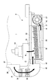
図9に示されるようにダクト部30は,装置本体1の高さ方向Hに関して,箱体部31の上端とほぼ同レベルの位置にある。ダクト部30におけるフィルター39より下流側に続けて,縦ダクト40が設けられている。図9に示されるように縦ダクト40は,箱体部31の側面に沿って縦方向に設けられている。そして,縦ダクト40の下端付近に,縦ダクト40と箱体部31との間の通気部41が設けられている。縦ダクト40により,ダクト部30を送風されてきた空気の箱体部31への流入位置が,高さ方向Hに関して,箱体部31の下端付近の位置とされている。すなわち当該空気は,箱体部31の上端とほぼ同レベルの位置でそのまま箱体部31へ流入するのではなく,縦ダクト40により下方に移動させられてから通気部41を通って箱体部31へ流入するのである(矢印B)。
As shown in FIG. 9, the
箱体部31には,図8および図9に示すようにフィルター室35が設けられている。フィルター室35には,フィルター36が設置されている。フィルター36は,静電フィルターである。フィルター室35は,箱体部31の中でダクト部30および縦ダクト40寄りに位置している。よって,通気部41から箱体部31へ流入する空気はまず,フィルター室35へ流入することとなる。
As shown in FIGS. 8 and 9, the
箱体部31の中でフィルター室35以外の位置には,排気ファン37が備えられている。排気ファン37は箱体部31の中で,ダクト部30から遠い側,すなわち格子部34の上方に位置している。さらに排気ファン37は,装置本体1の高さ方向Hに関しては,箱体部31の中で下寄りの位置に配置されている。そして排気ファン37は,図9中に矢印Fで示すように,上から下向きに,すなわち格子部34へ向かって送風するものである。排気ファン37のこの配置により,フィルター室35から排気ファン37の上流側の空間への通風は,排気ファン37より上方の通気部42を通ってなされることになる(矢印E)。
An
フィルター36は,全体として四角形状のものであり,装置本体1の背面にほぼ対面する向きに設置されている。ただし図8から分かるように,上方から見て,装置本体1の背面(図8中の水平方向)に対してやや傾斜した配置とされている。すなわち,ダクト部30により近い,図8,図9中の左側の方で装置本体1の背面からやや離れている。一方,ダクト部30からより遠い,図8,図9中の右側の方では装置本体1の背面に対して,左側と比較して近接している。
The
これにより図8に示されるように,通気部41からフィルター室35へ流入する空気は,フィルター室35におけるフィルター36よりも装置本体1側の空間へ流入することとなる(矢印C)。一方,フィルター室35の下流側では,装置本体1から見てフィルター36の向こう側の空間から,空気が通気部42を経て流出していくことになる(矢印E)。よって図9で見ると,通気部41からフィルター室35へ流入した空気は,通気部42へ向かって矢印Dのように斜め上向きに移動しつつ,フィルター36を通過することとなる。こうして,フィルター36を通過した空気が,通気部42を経て,排気ファン37により格子部34から機外へ下向きに放出されるのである。なお,通気部42が箱体部31の上下方向において上寄りの位置にあることで,排気ファン37を,下向きの排気に適した配置にしやすくなっている。
As a result, as shown in FIG. 8, the air flowing into the
さらに,装置本体1から図2に示した排気口20を通って排出された空気も,外付け排気フィルターユニット3に流入する。排気口20からの排気は,ダクト部30を通らずに,図3に示したを窓33を通って直接に箱体部31に流入する。もちろん図8に矢印Kで示されるように,排気口20からの排気もまずは,フィルター室35におけるフィルター36よりも装置本体1側の空間へ流入する。その後その排気ははむろん,フィルター36を通過してから通気部42を経て排気ファン37により機外へ下向きに放出されることとなる。なお,図2の説明では言及しなかったが,装置本体1の内部における排気口20の裏側の位置には,排気ファン43が設けられている。
Further, the air discharged from the apparatus
図9に示されるように,背面側から見ると,フィルター36で覆われている四角形の範囲の4つの頂点のうち,通気部41に最も近いものは,図中で左下の頂点である。通気部42に最も近い頂点は,図中で右上の頂点である。装置本体1の排気口20は,フィルター36で覆われている四角形の範囲内の左上の頂点付近に位置する。この位置は図9上,通気部41から通気部42へ向かう矢印Dから外れた位置にある。排気口20からの排気はこの位置から,図9中でほぼ水平右向き(矢印L)に移動しつつフィルター36を通過することとなる。
As shown in FIG. 9, when viewed from the back side, among the four vertices of the rectangular area covered with the
本形態では上記のように,装置本体1の開口21からの排気と,排気口20からの排気とで,フィルター室35内での通気経路を分けている(矢印Dと矢印L)。これにより排気全体が,フィルター36中の特定の箇所に集中してほぼその箇所のみを通過するのではなく,フィルター36のほぼ全体に分散して通過することとなる。このことにより,次のような効果がある。第1に,フィルター36による集塵効果が高いことである。第2に,フィルター36の寿命が長いことである。
In the present embodiment, as described above, the ventilation path in the
まず第1の効果について説明する。フィルター36は前述のように静電フィルターであり,通過する空気との摩擦により素繊維が帯電することで空気中の微粒子を吸着するものである。これにより,素繊維間の隙間より小さい微粒子でも捕捉できるので,集塵性と通気抵抗の低さとを両立できるものである。このため,集塵性能を適切に発揮するには,通過する空気の風速が好適な範囲内であることが求められる。風速が速すぎると静電引力では微粒子を吸着しきれないし,風速が遅すぎると素繊維の帯電が不十分となるからである。なお,装置本体1からの排気に含まれうる微粒子としては,定着器のローラーを構成するシリコンゴムが高温となることにより発生するUFP(ウルトラファインパーティクル)や,飛散したトナー,紙粉等がある。
First, the first effect will be described. The
もし縦ダクト40がないと,ダクト部30を搬送されてきた排気は,ダクト部30の高さレベルでそのままフィルター室35へ流入することとなる。この場合,図10に示すようにダクト部30からの排気は,フィルター36のほぼ上辺付近のみを通って通気部42へ向かうこととなる(矢印M)。そしてフィルター36の上辺付近というのは,排気口20からの排気の経路(矢印L)と重なる。このため排気全体で見ても,もっぱらフィルター36の上辺付近のみが通気に使用され,フィルター36の下半分程度はほとんど通気しない状態となる。したがって,フィルター36のうち,上辺付近では通過する空気の風速が速すぎ,下半分辺りでは逆に風速が遅すぎることとなる。このため,まともな集塵性能を発揮する部分が,上辺付近と下半分との間のごく限られた部分だけとなり,集塵性能が不十分となるのである。
If there is no
しかし本形態では前述のように,通気部41がフィルター36における図9中の左下端部付近に位置するようにしている。このため図9に示されるように,ダクト部30からの排気(矢印D)と排気口20からの排気(矢印L)とが集中せず,フィルター36のほぼ全面に近い広い範囲が通気に使用される。したがって,フィルター36のほぼ全面で,通過する空気の風速が好適な範囲内となる。このため,本来の集塵性能が十分に発揮されるのである。特に,通気部41が箱体部31の上下方向にえて下寄りの位置にあることで,通気部41から通気部42への経路(矢印D)が,フィルター36のほぼ対角線状をなすようになっている。
However, in this embodiment, as described above, the
次に第2の効果について説明する。図10に示したような状態では結局,フィルター36のうち上辺付近の部分のみが早期に詰まりを起こしてしまうことになる。素繊維間の隙間に機械的に引っ掛かるような大粒の粒子が,もっぱらこの部分のみに捕捉されるからである。このためフィルター36は,下半分程度がほぼ新品のままに近い状況であっても,早々に交換ないし清掃を強いられることになる。つまり,フィルター36の本来の寿命を有効活用できないのである。しかし本形態では図9に示したように排気がフィルター室35内で分散されて流れるので,フィルター36における大粒の粒子の集積もそのほぼ全体に分散して進行することになる。このため,フィルター36の交換または清掃を必要とする状況に至るまでの期間が長い。つまり,フィルター36の本来の寿命を有効に活用できるのである。
Next, the second effect will be described. In the state as shown in FIG. 10, only the portion near the upper side of the
本形態ではさらに,図8に示されるように,装置本体1の背面と箱体部31との間に,アタッチメント部材44が挟み込まれている。アタッチメント部材44について,図11,図12により説明する。図11は,ダクト部30および縦ダクト40を取り外した箱体部31と,アタッチメント部材44とを示している。図12は,そのうちのアタッチメント部材44の裏面側を示している。
Further, in this embodiment, as shown in FIG. 8, an
図11に示されるように箱体部31自体は,一方の面側が開放面となっているものである。その開放面が,装置本体1の背面に対面する面である。その開放面に対してアタッチメント部材44が取り付けられる。アタッチメント部材44は,全体が四角形状であるとともに窓33が形成されている平板状の部材である。アタッチメント部材44が取り付けられることにより箱体部31は,図3に示したような,窓33と格子部34とを除いてほぼ全面が閉鎖された直方体状となるのである。この状態の箱体部31が,ダクト部30および縦ダクト40とともに外付け排気フィルターユニット3を構成している。なお図11,図12では,箱体部31とアタッチメント部材44との組立やその他の部材の組付け等のための細部の構造まで描かれているが,これらは本発明としての特徴的事項ではないので説明を省略する。
As shown in FIG. 11, the
このアタッチメント部材44が介在することで,外付け排気フィルターユニット3の箱体部31と装置本体1の背面との間にある程度の間隔が確保されている。これにより,箱体部31がある程度高温になった場合でも,その影響が装置本体1にあまり及ばないようになっている。装置本体1では多くの場合,図5に示した開口21は,画像形成部10の構成要素の1つである定着器の近くに位置する。このため,開口21からの排気は,定着器の熱で高温になっている場合がある。したがって,箱体部31と装置本体1の背面とがあまり近接していると,箱体部31から装置本体1に熱が逆流してしまう場合がある。本形態では,箱体部31と装置本体1の背面との間にアタッチメント部材44を介在させることで,このような不都合を軽減している。
By interposing this
以上詳細に説明したように本実施の形態によれば,画像形成装置の装置本体1に取り付ける外付け排気フィルターユニット3において,ダクト部30からフィルター室35への通気部41と,フィルター室35から排気ファン37の上流側の空間への通気部42とが,フィルター36に対して対角線状に配置されるようにしている。これにより,ダクト部30を経由してきた排気が,フィルター36のうち狭い範囲でなく,広い範囲を通過するようにしている。こうして,フィルター36の集塵効率をよくするとともに,フィルター36の持つ本来の寿命を有効に活用するようにしている。
As described above in detail, according to the present embodiment, in the external
また,装置本体1の排気口20からの排気のフィルター室35への流入箇所を,ダクト部30からの排気のフィルター室35への通気部41から離れた箇所に置いている。このことによっても,フィルター36の全領域のうちの広い部分を有効に利用するようになっている。このようにして本形態では,フィルター36を装置本体1の背面に対向させて配置しつつ,かつ,フィルター36へ効率よく通気させてその寿命を有効活用するようにし
た外付け排気フィルターユニット3,およびそれを有する画像形成装置が実現されている。さらに,アタッチメント部材44により箱体部31と装置本体1の背面との間の間隔
を確保することで,箱体部31から装置本体1への熱の戻りを軽減している。
Further, an inflow portion of the exhaust gas from the
なお,本実施の形態は単なる例示にすぎず,本発明を何ら限定するものではない。したがって本発明は当然に,その要旨を逸脱しない範囲内で種々の改良,変形が可能である。例えば,装置本体1において,背面の排気口20は必須ではない。背面の排気口20を有しない装置本体1の場合,箱体部31の窓33は不要である。この場合でも,通気部41と通気部42との位置関係により,フィルター36の性能および寿命をより効果的に利用できることには変わりない。なお排気口20がある場合でも,その内側の排気ファン43(図8参照)は必須ではない。
Note that this embodiment is merely an example, and does not limit the present invention. Therefore, the present invention can naturally be improved and modified in various ways without departing from the gist thereof. For example, in the apparatus
また,縦ダクト40も必須ではない。本形態で縦ダクト40を使用したのは,図5の開口21と背面の排気口20とがほぼ同じくらいの高さレベルにあるからである。もし,開口21が排気口20より低い高さレベルに設けられているならば,縦ダクト40がなくてもフィルター室35において図9の通気経路が実現できることになる。それでもよい。また,図1に示した排気口19が,上部扉17のような可動パネルでなく固定パネルに形成されている場合には,その上に直接にダクト部30を設置する構成であってもよい。また,ダクト部30の送風ファン38およびフィルター39は,必須のものではない。また,フィルター36が静電フィルターであることも必須ではない。フィルター36が静電フィルターではない通常のフィルターであったとしても,その全面のうち,より広い範囲に通気させることで,フィルターの性能および寿命をより効率的に利用できることに変わりはないからである。
Further, the
また,フィルター室35における通気部41,通気部42,排気口20の位置関係は,必ずしも図示したとおりでなくてもよい。通気部41と通気部42との位置関係に関しては,要は,図9の視線方向で見て,これらが,フィルター36の面積重心位置を挟んで反対側に位置すればよい。具体的には図13の模式図に示すように,通気部41からフィルター36の面積重心位置Gを見る方向に対して偏向角θにして±30°以内の位置に通気部42の中心があれば,挟んで反対側に位置する,と見なしてよい。また,排気口20の位置については,通気部41と通気部42とを結ぶ線が排気口20から外れていればよい。具体的には図14の模式図に示すように,排気口20の占める領域を,通気部41と通気部42との中心同士を結ぶ線で切ったときの各小領域の大きい方の面積S1が小さい方の面積S2の2倍以上あれば,外れている,と見なしてよい。
Further, the positional relationship between the
また,アタッチメント部材44を有さず,箱体部31を直接に装置本体1の背面(もしくは側面)に取り付ける構成であってもよい。その場合,箱体部31から装置本体1への戻り熱が発生する可能性はあるが,もともと排気温度がそれほど高温にならない機種の場合は特に不都合はない。あるいは,箱体部31と装置本体1との間に何らかの断熱シートを設置することで対処することも可能である。また,画像形成部10は,前述のようなトナー方式のものに限らず,液状の発色材により画像を形成するものであってもよい。
Moreover, the structure which attaches the
1 装置本体
3 外付け排気フィルターユニット
10 画像形成部
20 排気口
21 開口
30 ダクト部
31 箱体部
33 窓
35 フィルター室
36 フィルター
41 通気部
42 通気部
44 アタッチメント部材
G 面積重心位置
DESCRIPTION OF
Claims (5)
装着状態では画像形成装置の外装面に沿って配置される箱体部と,
装着状態では画像形成装置の排気口を覆って配置され,排気口からの排気を前記箱体部に導くダクト部とを有し,
前記箱体部には,
前記フィルターを画像形成装置の外装面に対向させて収納するフィルター室と,
前記ダクト部から前記フィルター室における前記フィルターの前面側の空間へ排気を流入させる第1通気部と,
前記フィルター室における前記フィルターの後面側の空間から外部へ排気を放出させる第2通気部とが設けられており,
前記第1通気部と前記第2通気部とは,装着状態で前記画像形成装置の背後側から見て,前記フィルターの面積重心位置を挟んで反対側に位置することを特徴とする画像形成装置用外付け排気フィルターユニット。 An external exhaust filter unit for an image forming apparatus, which has a built-in filter and is attached to the image forming apparatus, and in the mounted state, takes in the exhaust from the exhaust port of the image forming apparatus and discharges it through the filter.
A box portion disposed along the exterior surface of the image forming apparatus in the mounted state;
In the mounted state, it is disposed so as to cover the exhaust port of the image forming apparatus, and has a duct portion that guides exhaust from the exhaust port to the box body,
In the box part,
A filter chamber for storing the filter facing the exterior surface of the image forming apparatus;
A first ventilation part for allowing exhaust to flow into the space on the front side of the filter in the filter chamber from the duct part;
A second ventilation part for releasing exhaust gas from the space on the rear surface side of the filter in the filter chamber to the outside;
The image forming apparatus characterized in that the first ventilation part and the second ventilation part are located on opposite sides of the area center of gravity of the filter when viewed from the back side of the image forming apparatus in a mounted state. External exhaust filter unit.
フィルターを内蔵し前記装置本体に装着され,装着状態では,前記排気口からの排気を取り込んで前記フィルターを通して外部へ放出するものである外付け排気フィルターユニットとを有する画像形成装置であって,
前記外付け排気フィルターユニットは,
装着状態では前記装置本体の外装面に沿って配置される箱体部と,
装着状態では前記排気口を覆って配置され,前記排気口からの排気を前記箱体部に導くダクト部とを有し,
前記箱体部には,
前記フィルターを前記装置本体の外装面に対向させて収納するフィルター室と,
前記ダクト部から前記フィルター室における前記フィルターの前面側の空間へ排気を流入させる第1通気部と,
前記フィルター室における前記フィルターの後面側の空間から外部へ排気を放出させる第2通気部とが設けられており,
前記第1通気部と前記第2通気部とは,装着状態で前記装置本体の背後側から見て,前記フィルターの面積重心位置を挟んで反対側に位置することを特徴とする画像形成装置。 An apparatus main body with a built-in image forming unit and an exhaust port for discharging air from the inside;
An image forming apparatus having an external exhaust filter unit that incorporates a filter and is attached to the apparatus main body, and in the attached state, takes in exhaust from the exhaust port and discharges it through the filter to the outside.
The external exhaust filter unit is
A box portion disposed along the exterior surface of the apparatus body in the mounted state;
In the mounted state, it is arranged so as to cover the exhaust port, and has a duct part that guides exhaust from the exhaust port to the box part,
In the box part,
A filter chamber for storing the filter facing the exterior surface of the apparatus body;
A first ventilation part for allowing exhaust to flow into the space on the front side of the filter in the filter chamber from the duct part;
A second ventilation part for releasing exhaust gas from the space on the rear surface side of the filter in the filter chamber to the outside;
The image forming apparatus, wherein the first ventilation part and the second ventilation part are located on opposite sides of the area center of gravity of the filter when viewed from the back side of the apparatus main body in a mounted state.
前記装置本体には,前記排気口として,側外装面の第1排気口と背外装面の第2排気口とが形成されており,
前記ダクト部は,装着状態では前記第1排気口と前記第2排気口とのうち第1排気口のみを覆うものであり,
前記箱体部は,
装着状態では前記装置本体の背外装面に沿って位置し,
装着状態で背外装面側となる面のうち,少なくとも装着状態で前記第2排気口と対面する範囲が開口しており,
装着状態で前記装置本体の背後側から見て,
前記フィルターを,前記フィルターが占める範囲内に前記第2排気口が位置するように保持するとともに,
前記第1通気部と前記第2通気部とを結ぶ線が,前記第2排気口から外れているものであることを特徴とする画像形成装置。 The image forming apparatus according to claim 2,
The apparatus body is formed with a first exhaust port on the side exterior surface and a second exhaust port on the back exterior surface as the exhaust port,
The duct portion covers only the first exhaust port among the first exhaust port and the second exhaust port in the mounted state,
The box part is
In the mounted state, it is located along the back exterior surface of the device body,
Of the surface on the back exterior surface side in the mounted state, at least the range facing the second exhaust port in the mounted state is open,
Seen from the back side of the device body in the mounted state,
Holding the filter so that the second exhaust port is located within a range occupied by the filter;
An image forming apparatus, wherein a line connecting the first ventilation portion and the second ventilation portion is disengaged from the second exhaust port.
前記フィルターは,全体が四角形状のものであり,
前記外付け排気フィルターユニットの装着状態で前記装置本体の背後側から見て,
前記フィルターの頂点のうち前記第1通気部に最も近いものは,下辺側の一方に位置する第1頂点であり,
前記フィルターの頂点のうち前記第2排気口に最も近いものは,前記第1頂点の上方に位置する第2頂点であり,
前記フィルターの頂点のうち前記第2通気部に最も近いものは,上辺側の2つの頂点のうち前記第2頂点でない方のものである第3頂点であることを特徴とする画像形成装置。 The image forming apparatus according to claim 3, wherein
The filter has a rectangular shape as a whole,
Seen from the back side of the apparatus body with the external exhaust filter unit mounted,
Of the vertices of the filter, the one closest to the first ventilation part is the first vertice located on one of the lower sides,
Of the apexes of the filter, the one closest to the second exhaust port is the second apex located above the first apex,
The image forming apparatus according to claim 1, wherein the vertex of the filter that is closest to the second ventilation portion is a third vertex that is not the second vertex of the two vertices on the upper side.
前記外付け排気フィルターユニットの装着状態にて前記装置本体と前記箱体部との間に挟持され,前記装置本体と前記箱体部との間に空間を確保するアタッチメント部材を有することを特徴とする画像形成装置。 An image forming apparatus according to any one of claims 2 to 4, comprising:
It has an attachment member that is sandwiched between the apparatus main body and the box body portion in a mounted state of the external exhaust filter unit, and secures a space between the apparatus main body and the box body portion. Image forming apparatus.
Priority Applications (1)
| Application Number | Priority Date | Filing Date | Title |
|---|---|---|---|
| JP2015153791A JP6561665B2 (en) | 2015-08-04 | 2015-08-04 | External exhaust filter unit for image forming apparatus and image forming apparatus |
Applications Claiming Priority (1)
| Application Number | Priority Date | Filing Date | Title |
|---|---|---|---|
| JP2015153791A JP6561665B2 (en) | 2015-08-04 | 2015-08-04 | External exhaust filter unit for image forming apparatus and image forming apparatus |
Publications (2)
| Publication Number | Publication Date |
|---|---|
| JP2017032833A JP2017032833A (en) | 2017-02-09 |
| JP6561665B2 true JP6561665B2 (en) | 2019-08-21 |
Family
ID=57988048
Family Applications (1)
| Application Number | Title | Priority Date | Filing Date |
|---|---|---|---|
| JP2015153791A Active JP6561665B2 (en) | 2015-08-04 | 2015-08-04 | External exhaust filter unit for image forming apparatus and image forming apparatus |
Country Status (1)
| Country | Link |
|---|---|
| JP (1) | JP6561665B2 (en) |
Families Citing this family (3)
| Publication number | Priority date | Publication date | Assignee | Title |
|---|---|---|---|---|
| WO2018190332A1 (en) * | 2017-04-14 | 2018-10-18 | 富士フイルム株式会社 | Ink jet recording apparatus and cooling method |
| EP3835875A4 (en) | 2018-08-09 | 2022-04-20 | Canon Kabushiki Kaisha | Image-forming device |
| JP7071242B2 (en) | 2018-08-09 | 2022-05-18 | キヤノン株式会社 | Image forming device |
Family Cites Families (17)
| Publication number | Priority date | Publication date | Assignee | Title |
|---|---|---|---|---|
| JPH11202633A (en) * | 1998-01-09 | 1999-07-30 | Toray Ind Inc | Liquid agent recovering device and method and image forming device |
| JP3825912B2 (en) * | 1998-04-03 | 2006-09-27 | 株式会社リコー | Electronic device exhaust device and electronic device using the same |
| JP3893321B2 (en) * | 2002-05-24 | 2007-03-14 | キヤノン株式会社 | Image forming apparatus |
| JP4266771B2 (en) * | 2003-10-27 | 2009-05-20 | 京セラミタ株式会社 | Image forming apparatus |
| JP4622436B2 (en) * | 2004-10-07 | 2011-02-02 | パナソニック株式会社 | Air purification unit |
| JP3994996B2 (en) * | 2004-10-18 | 2007-10-24 | コニカミノルタビジネステクノロジーズ株式会社 | Image forming apparatus |
| JP2006208718A (en) * | 2005-01-27 | 2006-08-10 | Canon Inc | Image forming apparatus |
| JP4636955B2 (en) * | 2005-07-06 | 2011-02-23 | キヤノン株式会社 | Air processing apparatus and image forming system |
| JP5045270B2 (en) * | 2007-07-02 | 2012-10-10 | コニカミノルタビジネステクノロジーズ株式会社 | Image forming apparatus |
| JP2010079047A (en) * | 2008-09-26 | 2010-04-08 | Brother Ind Ltd | Image forming apparatus |
| JP5471557B2 (en) * | 2010-02-15 | 2014-04-16 | 株式会社リコー | Image forming apparatus |
| KR20130084091A (en) * | 2012-01-16 | 2013-07-24 | 삼성전자주식회사 | Image forming apparatus |
| JP2014044238A (en) * | 2012-08-24 | 2014-03-13 | Canon Inc | Image forming device |
| JP2014085556A (en) * | 2012-10-24 | 2014-05-12 | Fuji Xerox Co Ltd | Image forming apparatus and separation apparatus for collecting toner |
| JP5915590B2 (en) * | 2013-05-15 | 2016-05-11 | コニカミノルタ株式会社 | Image forming apparatus |
| JP2016031428A (en) * | 2014-07-28 | 2016-03-07 | 株式会社リコー | Image forming apparatus |
| JP6455122B2 (en) * | 2014-12-15 | 2019-01-23 | コニカミノルタ株式会社 | Exhaust purification device |
-
2015
- 2015-08-04 JP JP2015153791A patent/JP6561665B2/en active Active
Also Published As
| Publication number | Publication date |
|---|---|
| JP2017032833A (en) | 2017-02-09 |
Similar Documents
| Publication | Publication Date | Title |
|---|---|---|
| JP4712096B2 (en) | Air intake structure for automobiles | |
| JP6561665B2 (en) | External exhaust filter unit for image forming apparatus and image forming apparatus | |
| JP2008077077A (en) | Image forming apparatus | |
| WO2015141023A1 (en) | Blower | |
| JP5520901B2 (en) | Air cleaner | |
| RU2553962C2 (en) | Air blower unit | |
| JP5424370B2 (en) | Cover member for projection display device | |
| WO2013140895A1 (en) | Indoor air conditioner | |
| JP5834764B2 (en) | Image forming apparatus and collection apparatus | |
| JP7015986B2 (en) | Dustproof filter | |
| JP5589441B2 (en) | Filter device and projector device | |
| JP6064162B2 (en) | Air purifier | |
| WO2016114059A1 (en) | Air purifier | |
| WO2019239649A1 (en) | Indoor unit for air conditioner | |
| TWI664378B (en) | Swing leaves and air supply device | |
| JP5693413B2 (en) | Indoor unit of ceiling-embedded air conditioner | |
| WO2020008597A1 (en) | Heat exchange ventilator | |
| JP5823139B2 (en) | Heat exchange ventilator | |
| JP2023033663A (en) | air conditioner | |
| JP5741546B2 (en) | Outdoor unit | |
| JP5800740B2 (en) | Air conditioner indoor unit | |
| JP6656965B2 (en) | Air cleaner | |
| JP4228722B2 (en) | Suction prevention structure for vehicle air conditioner | |
| JP6770954B2 (en) | Air compressor | |
| JP6036182B2 (en) | Ventilation equipment |
Legal Events
| Date | Code | Title | Description |
|---|---|---|---|
| A621 | Written request for application examination |
Free format text: JAPANESE INTERMEDIATE CODE: A621 Effective date: 20180518 |
|
| A977 | Report on retrieval |
Free format text: JAPANESE INTERMEDIATE CODE: A971007 Effective date: 20190227 |
|
| A131 | Notification of reasons for refusal |
Free format text: JAPANESE INTERMEDIATE CODE: A131 Effective date: 20190305 |
|
| TRDD | Decision of grant or rejection written | ||
| A01 | Written decision to grant a patent or to grant a registration (utility model) |
Free format text: JAPANESE INTERMEDIATE CODE: A01 Effective date: 20190625 |
|
| A61 | First payment of annual fees (during grant procedure) |
Free format text: JAPANESE INTERMEDIATE CODE: A61 Effective date: 20190708 |
|
| R150 | Certificate of patent or registration of utility model |
Ref document number: 6561665 Country of ref document: JP Free format text: JAPANESE INTERMEDIATE CODE: R150 |