JP6455122B2 - Exhaust purification device - Google Patents
Exhaust purification device Download PDFInfo
- Publication number
- JP6455122B2 JP6455122B2 JP2014252743A JP2014252743A JP6455122B2 JP 6455122 B2 JP6455122 B2 JP 6455122B2 JP 2014252743 A JP2014252743 A JP 2014252743A JP 2014252743 A JP2014252743 A JP 2014252743A JP 6455122 B2 JP6455122 B2 JP 6455122B2
- Authority
- JP
- Japan
- Prior art keywords
- inflow
- exhaust
- value
- fan
- air
- Prior art date
- Legal status (The legal status is an assumption and is not a legal conclusion. Google has not performed a legal analysis and makes no representation as to the accuracy of the status listed.)
- Active
Links
Images


Description
本発明は,画像形成装置の排気を浄化する排気浄化装置に関する。さらに詳細には,画像形成に伴って発生する副産物を含む画像形成装置の排気を浄化する排気浄化装置に関する。 The present invention relates to an exhaust gas purification device that purifies exhaust gas from an image forming apparatus. More specifically, the present invention relates to an exhaust gas purification device that purifies exhaust gas from an image forming apparatus that includes by-products generated during image formation.
従来より,複写機やプリンター,ファクシミリ,またはこれらの機能を複合的に備える複合機等の画像形成装置では,画像形成により,装置内において様々な副産物が発生することが知られている。副産物には,例えば,臭気,VOC(Volatile Organic Compounds:揮発性有機化合物),低分子シロキサンおよび粉塵(トナーや紙粉等)等が挙げられる。そして,通常,画像形成装置では,副産物の発生箇所よりこれを吸引し,一定の規格に基づいたフィルターによって吸引した副産物を捕集することにより,副産物が機外に排出されないようにされている。 2. Description of the Related Art Conventionally, it is known that various by-products are generated in an image forming apparatus such as a copying machine, a printer, a facsimile machine, or a multi-function machine having a combination of these functions. By-products include, for example, odor, VOC (Volatile Organic Compounds), low molecular siloxane, and dust (toner, paper powder, etc.). Usually, in the image forming apparatus, the by-product is sucked from a place where the by-product is generated, and the by-product sucked by a filter based on a certain standard is collected so that the by-product is not discharged outside the apparatus.
このような副産物を捕集するようにした画像形成装置として,特許文献1が挙げられる。特許文献1には,装置本体の背面に,機内からの排気を行うための排気ファンや,副産物を捕集するためのフィルターを備える外部排気ダクトを設けた画像形成装置が開示されている。外部排気ダクトは装置本体の背面よりも出っ張っており,装置背面の外部排気ダクトの箇所以外の箇所には,機内の冷却を目的とする副産物の含まれない空気を排気するための冷却用の排気口が設けられている。そして,このような構成の画像形成装置では,背面側が壁に密着するように設置したとしても,外部排気ダクトが設けられていることにより冷却用の排気口が壁によって塞がれることがなく,冷却排気がスムーズに行うことができるとされている。また,装置背面の外部排気ダクトは装置本体から取外しが可能であるため,間口の狭い部屋などへの搬入も可能であり,物流性が改善されるとされている。 Patent Document 1 is an example of an image forming apparatus that collects such a by-product. Patent Document 1 discloses an image forming apparatus in which an exhaust fan for exhausting air from inside the apparatus and an external exhaust duct having a filter for collecting by-products are provided on the back of the apparatus main body. The external exhaust duct protrudes from the back of the equipment body, and the exhaust for cooling air that does not contain by-products for the purpose of cooling inside the machine is provided at locations other than the external exhaust duct on the back of the equipment. Mouth is provided. In the image forming apparatus having such a configuration, even if the back side is installed so as to be in close contact with the wall, the external exhaust duct is provided so that the cooling exhaust port is not blocked by the wall. It is said that cooling and exhaust can be performed smoothly. Also, since the external exhaust duct on the back of the device can be removed from the device main body, it can be carried into a room with a narrow frontage, which improves logistics.
ところで,画像形成装置の一部のユーザーには,フィルターを通過することにより規格が満たされている排気についても,さらに浄化してほしいというニーズがある。そこで,すでに設置してある画像形成装置の排気口に,その排気をさらに浄化するための浄化フィルターを備える,特許文献1の外部排気ダクトのような排気浄化装置を後付けで取り付けることが考えられる。 Incidentally, some users of the image forming apparatus have a need to further purify the exhaust gas that satisfies the standard by passing through the filter. In view of this, it is conceivable that an exhaust purification device such as an external exhaust duct of Patent Document 1 having a purification filter for further purifying the exhaust gas is retrofitted to the exhaust port of the image forming apparatus already installed.
そして,画像形成装置に後付けで取り付けられた排気浄化装置は,画像形成装置の排気口からの排気に影響を及ぼすことがないように,その排気を浄化するものであることが好ましい。例えば,排気浄化装置からの排気風量が,排気浄化装置が取り付けられた画像形成装置からの排気風量よりも多い場合,画像形成装置の機内温度を低下させ過ぎてしまうおそれがある。この場合,画像形成装置の定着部の温度が低下し過ぎてしまい,画像形成装置により形成される画像の品質を低下させてしまうおそれがあるからである。 The exhaust purification device attached to the image forming apparatus as a retrofit preferably purifies the exhaust so as not to affect the exhaust from the exhaust port of the image forming apparatus. For example, when the amount of exhaust air from the exhaust purification device is larger than the amount of exhaust air from the image forming apparatus to which the exhaust purification device is attached, there is a risk that the in-machine temperature of the image forming device will be excessively lowered. In this case, the temperature of the fixing unit of the image forming apparatus may be excessively lowered, and the quality of the image formed by the image forming apparatus may be deteriorated.
一方,例えば,排気浄化装置からの排気風量が少な過ぎる場合には,画像形成装置からの排気を阻害してしまうこととなる。この場合,画像形成装置の機内温度を上昇させ過ぎてしまうおそれがある。さらには,画像形成装置内で発生した副産物が適切に回収されず,機内に副産物が残留してしまう。これらのような状態は,画像形成装置の故障の原因となってしまうおそれがある。 On the other hand, for example, when the amount of exhaust air from the exhaust purification device is too small, the exhaust from the image forming apparatus is hindered. In this case, the temperature inside the image forming apparatus may be excessively increased. Furthermore, the by-product generated in the image forming apparatus is not properly collected, and the by-product remains in the apparatus. Such a state may cause a failure of the image forming apparatus.
本発明は,前記した従来の技術が有する問題点の解決を目的としてなされたものである。すなわちその課題とするところは,画像形成装置の画像形成に係る機器への悪影響や,形成される画像の品質低下を抑制しつつ,画像形成に伴って発生する副産物を適切に回収することのできる排気浄化装置を提供することである。 The present invention has been made for the purpose of solving the problems of the prior art described above. That is, the problem is that it is possible to appropriately collect by-products generated during image formation while suppressing adverse effects on the image forming apparatus of the image forming apparatus and deterioration of the quality of the formed image. An exhaust purification device is provided.
この課題の解決を目的としてなされた本発明の一態様に係る排気浄化装置は,画像形成装置の排気口から排気された空気を浄化する浄化ダクトと,浄化ダクトの内部に連通し,画像形成装置の排気口と接続するための開口が形成されている流入部と,浄化ダクトの内部の空気を浄化ダクトの外部に排出するための排出口とを有する排気浄化装置であって,浄化ダクト内の流入部から排出口までの間に設けられた,流入部から排出口に向かう向きに空気を流すファンと,通過する空気中の微粒子を回収するフィルターと,流入部の開口より流入してくる空気の流量を指標する流入値を検出して出力する流入値出力部とを有するとともに,予め定めた流入値とファンの回転数との関係である流入値回転数テーブルを記憶するテーブル記憶部と,ファンを,その回転数を制御しつつ駆動する回転数制御部とを有し,回転数制御部は,流入値出力部が出力する流入値が予め定めた駆動閾値未満であるときには,ファンを停止状態とし,流入値出力部が出力する流入値が駆動閾値以上であるときには,流入値により流入値回転数テーブルを参照してファンの回転数を定めるとともに,定めた回転数でファンを駆動する流入値制御を実行するものであることを特徴とする排気浄化装置である。本発明の排気浄化装置は,流入値制御において,浄化ダクト内への流入値により流入値回転数テーブルを参照して設定した回転数で,ファンを回転する。流入値回転数テーブルは,予め定めた流入値とファンの回転数との関係であるため,流入値制御では,流入値に対して適した回転数を定めることができる。これにより,排気浄化装置は,画像形成装置における画像形成に係る機器への悪影響や,形成される画像の品質低下を抑制しつつ,フィルターにより画像形成装置の排気を浄化することができる。さらに,駆動閾値未満であるときのファンの駆動を停止させることにより,省電力であるとともに騒音を低減することができる。加えて,ファンの寿命についても長くすることができる。 An exhaust emission control device according to an aspect of the present invention for solving this problem includes a purification duct for purifying air exhausted from an exhaust port of an image forming apparatus, an interior of the purification duct, and An exhaust purification device having an inflow portion in which an opening for connection to an exhaust port of the exhaust gas is formed and an exhaust port for discharging air inside the purification duct to the outside of the purification duct. A fan installed between the inlet and the outlet that flows air in the direction from the inlet to the outlet, a filter that collects particulates in the passing air, and the air that flows in from the opening of the inlet An inflow value output unit that detects and outputs an inflow value that indicates the flow rate of the air, and a table storage unit that stores an inflow value rotational speed table that is a relationship between a predetermined inflow value and the rotational speed of the fan; F The emissions, and a rotation speed control unit for driving while controlling the rotational speed, the rotational speed control section, when the inflow values inflow value output section outputs is less than the predetermined driving threshold, stops the fan When the inflow value output from the inflow value output unit is equal to or greater than the drive threshold value, the inflow value rotation speed table is referred to the inflow value rotation speed table based on the inflow value, and the fan is driven at the determined rotation speed. An exhaust emission control device that performs value control . In the inflow value control, the exhaust purification apparatus of the present invention rotates the fan at the rotation speed set by referring to the inflow value rotation speed table according to the inflow value into the purification duct. Since the inflow value rotation speed table has a relationship between a predetermined inflow value and the rotation speed of the fan, the inflow value control can determine a rotation speed suitable for the inflow value. As a result, the exhaust emission control device can purify the exhaust gas of the image forming apparatus with the filter while suppressing adverse effects on the apparatus related to image formation in the image forming apparatus and deterioration of the quality of the formed image. Furthermore, by stopping the driving of the fan when it is less than the driving threshold, it is possible to save power and reduce noise. In addition, the life of the fan can be extended.
また,本発明の他の態様に係る排気浄化装置は,画像形成装置の排気口から排気された空気を浄化する浄化ダクトと,浄化ダクトの内部に連通し,画像形成装置の排気口と接続するための開口が形成されている流入部と,浄化ダクトの内部の空気を浄化ダクトの外部に排出するための排出口とを有する排気浄化装置であって,浄化ダクト内の流入部から排出口までの間に設けられた,流入部から排出口に向かう向きに空気を流すファンと,通過する空気中の微粒子を回収するフィルターと,流入部の開口より流入してくる空気の流量を指標する流入値を検出して出力する流入値出力部とを有するとともに,予め定めた流入値とファンの回転数との関係である流入値回転数テーブルを記憶するテーブル記憶部と,ファンを,その回転数を制御しつつ駆動する回転数制御部と,流入部が接続される画像形成装置の機種を指標する機種値を出力する機種値出力部とを有し,テーブル記憶部は,流入値回転数テーブルを,流入部が接続される画像形成装置の機種ごとに複数,有するものであり,回転数制御部は,流入値出力部が出力する流入値により流入値回転数テーブルを参照してファンの回転数を定めるとともに,定めた回転数でファンを駆動する流入値制御を実行するものであり,流入部が画像形成装置に接続されてから流入値制御を開始するまでの間に,機種値出力部が出力した機種値により,流入値制御で用いる流入値回転数テーブルを定めるテーブル設定を行い,流入値制御を,テーブル設定で定めた流入値回転数テーブルを用いて実行するものであることを特徴とする排気浄化装置である。本発明の排気浄化装置は,複数の画像形成装置の機種に対応することができる。これにより,複数の機種のうち,どの機種の画像形成装置に取り付けられたとしても,画像形成に係る機器への悪影響や,形成される画像の品質低下を抑制しつつ,画像形成に伴い発生する副産物を適切に回収することができる。 According to another aspect of the present invention, there is provided an exhaust purification apparatus that purifies air exhausted from an exhaust port of an image forming apparatus, communicates with the interior of the purification duct, and connects to the exhaust port of the image forming apparatus. An exhaust gas purification apparatus having an inflow portion in which an opening for forming a gas is formed and an exhaust port for discharging air inside the purification duct to the outside of the purification duct, from the inflow portion to the exhaust port in the purification duct , A fan that flows air in the direction from the inlet to the outlet, a filter that collects particulates in the passing air, and an inflow that indicates the flow rate of air flowing in from the opening of the inlet An inflow value output unit for detecting and outputting a value, a table storage unit for storing an inflow value rotation number table, which is a relationship between a predetermined inflow value and the rotation number of the fan, and the fan with its rotation number Control One and a rotation speed control unit for driving, and a model value output unit inlet portion outputs a model value that indicates the type of an image forming apparatus connected, the table storage unit, the inflow values rotational speed table, the inflow The rotational speed control unit determines the rotational speed of the fan by referring to the inflow value rotational speed table based on the inflow value output from the inflow value output unit. At the same time, inflow value control is performed to drive the fan at a predetermined number of revolutions . The model value output section outputs the inflow value control after the inflow section is connected to the image forming apparatus. Exhaust gas characterized in that table setting for determining an inflow value rotation speed table used in inflow value control is performed according to the model value, and inflow value control is executed using the inflow value rotation speed table determined in the table setting. Clean It is a device. Exhaust purification system of the present invention, Ru can be corresponding to the model of a plurality of image forming apparatus. As a result, even if it is attached to any type of image forming apparatus among a plurality of models, it occurs with image formation while suppressing adverse effects on the apparatus related to image formation and deterioration of the quality of the formed image. Ru can be properly recovered by-products.
また,本発明の他の態様に係る排気浄化装置は,画像形成装置の排気口から排気された空気を浄化する浄化ダクトと,浄化ダクトの内部に連通し,画像形成装置の排気口と接続するための開口が形成されている流入部と,浄化ダクトの内部の空気を浄化ダクトの外部に排出するための排出口とを有する排気浄化装置であって,浄化ダクト内の流入部から排出口までの間に設けられた,流入部から排出口に向かう向きに空気を流すファンと,通過する空気中の微粒子を回収するフィルターと,流入部の開口より流入してくる空気の流量を指標する流入値を検出して出力する流入値出力部とを有するとともに,予め定めた流入値とファンの回転数との関係である流入値回転数テーブルを記憶するテーブル記憶部と,ファンを,その回転数を制御しつつ駆動する回転数制御部と,排出口から排出される空気の流量を指標する排出値を検出して出力する排出値出力部とを有し,回転数制御部は,流入値出力部が出力する流入値により流入値回転数テーブルを参照してファンの回転数を定めるとともに,定めた回転数でファンを駆動する流入値制御を実行し,流入値制御を実行した後には,流入値出力部が出力する流入値と排出値出力部が出力する排出値とを比較するとともに,排出値が流入値よりも高い値であるときには,ファンの回転数を低くし,排出値が流入値よりも低い値であるときには,ファンの回転数を高くする流入排出値制御を,流入値制御よりも優先して行うものであることを特徴とする排気浄化装置である。本発明の排気浄化装置は,画像形成に係る機器への悪影響や,形成される画像の品質低下をより確実に抑制しつつ,画像形成に伴い発生する副産物を適切に回収することができる。 According to another aspect of the present invention, there is provided an exhaust purification apparatus that purifies air exhausted from an exhaust port of an image forming apparatus, communicates with the interior of the purification duct, and connects to the exhaust port of the image forming apparatus. An exhaust gas purification apparatus having an inflow portion in which an opening for forming a gas is formed and an exhaust port for discharging air inside the purification duct to the outside of the purification duct, from the inflow portion to the exhaust port in the purification duct , A fan that flows air in the direction from the inlet to the outlet, a filter that collects particulates in the passing air, and an inflow that indicates the flow rate of air flowing in from the opening of the inlet An inflow value output unit for detecting and outputting a value, a table storage unit for storing an inflow value rotation number table, which is a relationship between a predetermined inflow value and the rotation number of the fan, and the fan with its rotation number Control One and a rotation speed control unit for driving, and an emission value output unit detects and outputs a discharge value that indicates the flow rate of the air discharged from the discharge port, the rotation speed control unit, inflow value output section outputs The inflow value rotational speed table is determined by referring to the inflow value rotation speed table, and the inflow value control for driving the fan at the determined rotation speed is executed. Compares the inflow value output from the exhaust with the exhaust value output from the exhaust value output unit, and if the exhaust value is higher than the inflow value, the fan speed is lowered and the exhaust value is lower than the inflow value. When the value is a value, the exhaust gas purification apparatus is characterized in that inflow / exhaust value control for increasing the rotational speed of the fan is performed in preference to inflow value control . Exhaust purification system of the present invention, and adverse effects on the device according to the image formation, while more reliably suppress the quality degradation of an image to be formed, the byproducts generated with the image forming Ru can be properly recovered.
また,上記に記載の排気浄化装置において,排出値出力部は,ファンおよびフィルターよりも,ファンの駆動により移動する空気の移動方向の下流側に設けられているものであることが好ましい。排出値出力部により,排出値を正確に検出することができるからである。 In the exhaust emission control device described above, it is preferable that the emission value output unit is provided on the downstream side in the moving direction of the air moving by driving the fan, rather than the fan and the filter. This is because the emission value can be accurately detected by the emission value output unit.
また,上記に記載の排気浄化装置において,排出値出力部は,排出値として,排出口から排出される空気の流速を検出するものであってもよい。 Moreover, in the exhaust emission control device described above, the emission value output unit may detect a flow velocity of air discharged from the outlet as an emission value.
また,上記に記載の排気浄化装置において,回転数制御部は,流入排出値制御では,流入値出力部が出力する流入値と排出値出力部が出力する排出値との差である流入排出差を算出し,流入排出差が予め定めた許容差を,予め定めた許容時間以上,超えていない場合には,流入排出値制御を続行し,流入排出差が許容差を,許容時間以上,超えていた場合には,ファンを停止させるものであることが好ましい。排気浄化装置が故障しているおそれがあるからである。 In the exhaust emission control device described above, the rotation speed control unit, in the inflow / exhaust value control, is an inflow / exhaust difference that is a difference between an inflow value output from the inflow value output unit and an exhaust value output from the exhaust value output unit. If the inflow / discharge difference does not exceed the predetermined tolerance for the predetermined allowable time or more, the inflow / discharge value control is continued, and the inflow / discharge difference exceeds the allowable time for the allowable time or more. In such a case, it is preferable to stop the fan. This is because the exhaust purification device may be broken.
また,本発明の他の態様に係る排気浄化装置は,画像形成装置の排気口から排気された空気を浄化する浄化ダクトと,浄化ダクトの内部に連通し,画像形成装置の排気口と接続するための開口が形成されている流入部と,浄化ダクトの内部の空気を浄化ダクトの外部に排出するための排出口とを有する排気浄化装置であって,浄化ダクト内の流入部から排出口までの間に設けられた,流入部から排出口に向かう向きに空気を流すファンと,通過する空気中の微粒子を回収するフィルターと,流入部の開口より流入してくる空気の流量を指標する流入値を検出して出力する流入値出力部とを有するとともに,予め定めた流入値とファンの回転数との関係である流入値回転数テーブルを記憶するテーブル記憶部と,ファンを,その回転数を制御しつつ駆動する回転数制御部と,流入値出力部が出力する流入値が予め定めた初期閾値未満から初期閾値以上となったときの流入値を,初期流入値として検出する初期流入値検出部と,初期流入値検出部が検出した初期流入値を記憶する初期流入値記憶部とを有し,回転数制御部は,初期流入値検出部が初期流入値を検出したときから予め定めた初期回転時間だけ,ファンを,予め定めた初期回転数で駆動する初期回転制御を実行し,初期回転制御の実行後,流入値出力部が出力する流入値により流入値回転数テーブルを参照してファンの回転数を定めるとともに,定めた回転数でファンを駆動する流入値制御を実行し,流入値制御では,初期流入値により流入値回転数テーブルを参照して定めた回転数でファンの駆動を開始するものであることを特徴とする排気浄化装置である。本発明の排気浄化装置は,いわゆるイニシャルバーストにおいて大量に発生した副産物を,適切にフィルターによって捕集させることができる。 According to another aspect of the present invention, there is provided an exhaust purification apparatus that purifies air exhausted from an exhaust port of an image forming apparatus, communicates with the interior of the purification duct, and connects to the exhaust port of the image forming apparatus. An exhaust gas purification apparatus having an inflow portion in which an opening for forming a gas is formed and an exhaust port for discharging air inside the purification duct to the outside of the purification duct, from the inflow portion to the exhaust port in the purification duct , A fan that flows air in the direction from the inlet to the outlet, a filter that collects particulates in the passing air, and an inflow that indicates the flow rate of air flowing in from the opening of the inlet An inflow value output unit for detecting and outputting a value, a table storage unit for storing an inflow value rotation number table, which is a relationship between a predetermined inflow value and the rotation number of the fan, and the fan with its rotation number Control A rotation speed control unit that drives One, the inflow value when the inflow values inflow value output unit outputs is equal to or greater than the initial threshold from less than a predetermined initial threshold, the initial inflow value detector for detecting an initial inflow value An initial inflow value storage unit for storing the initial inflow value detected by the initial inflow value detection unit, and the rotation speed control unit is configured to perform a predetermined initial rotation from when the initial inflow value detection unit detects the initial inflow value. Execute the initial rotation control for driving the fan at a predetermined initial rotation speed only for the time, and after executing the initial rotation control , refer to the inflow value rotation speed table by the inflow value output from the inflow value output section. The inflow value control for driving the fan at the determined rotation speed is executed while the rotation speed is determined, and in the inflow value control, the fan driving is started at the rotation speed determined by referring to the inflow value rotation speed table based on the initial inflow value. this is intended to An exhaust purification device according to claim. Exhaust purification system of the present invention, a large amount byproducts generated in the so-called initial burst, Ru can be collected properly by the filter.
また,上記に記載の排気浄化装置において,初期回転数は,初期流入値により流入値回転数テーブルを参照して定められるファンの回転数よりも低い回転数であることが好ましい。画像形成装置の排気のフィルターの通過速度を遅くすることで,その排気に含まれている副産物の捕集率を高めることができるからである。 In the exhaust purification apparatus described above, the initial rotational speed is preferably lower than the rotational speed of the fan determined by referring to the inflow value rotational speed table based on the initial inflow value. This is because by reducing the passage speed of the exhaust filter of the image forming apparatus, the collection rate of by-products contained in the exhaust can be increased.
また,上記に記載の排気浄化装置において,流入値出力部は,ファンおよびフィルターよりも,流入部の開口の側に設けられているものであることが好ましい。流入値出力部により,ファンやフィルターによって変化してしまう前の画像形成装置の排気に係る流入値を,正確に検出することができるからである。 In the exhaust gas purification apparatus described above, it is preferable that the inflow value output unit is provided closer to the opening of the inflow unit than the fan and the filter. This is because the inflow value output unit can accurately detect the inflow value relating to the exhaust of the image forming apparatus before it is changed by the fan or the filter.
また,上記に記載の排気浄化装置において,流入値出力部は,流入値として,流入部の開口より流入してくる空気の流速を検出するものであってもよい。 In the exhaust gas purification apparatus described above, the inflow value output unit may detect the flow rate of air flowing in from the opening of the inflow unit as the inflow value.
本発明によれば,画像形成装置の画像形成に係る機器への悪影響や,形成される画像の品質低下を抑制しつつ,画像形成に伴って発生する副産物を適切に回収することのできる排気浄化装置が提供されている。 According to the present invention, exhaust purification that can properly recover by-products generated during image formation while suppressing adverse effects on the apparatus related to image formation of the image forming apparatus and deterioration of the quality of the formed image. A device is provided.
以下,本発明を具体化した形態について,図面を参照しつつ詳細に説明する。 Hereinafter, embodiments of the present invention will be described in detail with reference to the drawings.
[第1の形態]
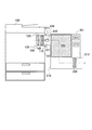
まず,第1の形態について,添付図面を参照しつつ説明する。本形態は,図1に概略構成を示すように,画像形成装置100の排気口110に接続して用いられる,画像形成装置用の排気浄化装置201に係るものである。画像形成装置100は,電子写真方式によりトナー像をシート上に定着させて画像を形成するものである。
[First embodiment]
First, the first embodiment will be described with reference to the attached drawings. This embodiment relates to an exhaust
図1に示す画像形成装置100は,その側面101に排気口110を有している。排気口110は,画像形成装置100の装置内部の空気を機外へ排出するための開口部である。排気口110の装置内部側には,機内ダクト120が設けられている。機内ダクト120の排気口110と反対側の端は,機内で開口している吸入口130である。吸入口130は,トナー像を形成するための現像装置や,形成されたトナー像のシートへの定着処理を行う定着装置の付近などに開口している。
An
また,機内ダクト120内には,機内ファン140および機内フィルター150が設けられている。機内ファン140は,機内ダクト120内の空気を機外へ排出するためのものである。
An in-
機内フィルター150は,その位置を通過する空気に含まれている副産物を,一定の規格に基づいて回収するためのものである。副産物は,シートへ適切に定着されなかったトナーや,定着処理時にトナーが溶融することにより生成される低分子シロキサンなど,画像形成装置100内で発生するものである。
The in-
そして,機内ファン140が駆動されると,吸入口130の付近の空気は,機内ダクト120内へと吸入される。このとき,吸入口130の付近の副産物についても,空気とともに,機内ダクト120内へと吸入される。機内ダクト120内の空気は,機内フィルター150を通ることにより副産物が除去された後,排気口110より画像形成装置100の外部に排出される。これにより,画像形成装置100では,排気口110から排出される空気が,一定の規格を満たした無害なものであるようにされている。
When the in-
しかし,画像形成装置100のユーザーには,このような一定の規格を満たすことにより無害化された排気についても,さらに浄化してほしいという要望があることがある。すなわち,排気口110から排出される空気の中には,機内フィルター150によって捕集できない副産物が含まれていることがあるからである。
However, there is a demand for users of the
排気口110から排出される副産物には,例えば,機内フィルター150によって捕集することのできる副産物の最小粒径よりもさらに小さい粒径の副産物などである。そして,図1に示す排気浄化装置201は,このような機内フィルター150によって回収できない副産物を回収するためのものである。
The by-products discharged from the
排気浄化装置201は,浄化ダクト210を有しており,その流入部220の先端に設けられている取付フランジ211において,画像形成装置100の側面101に取り付けられている。排気浄化装置201の取付フランジ211は,画像形成装置100の側面101に固定されている。
The
流入部220には,排気浄化装置201の浄化ダクト210内部に繋がる開口部221が形成されている。排気浄化装置201について,流入部220の開口部221が形成されている位置は,図1に示すように,画像形成装置100の排気口110に対応する位置である。このため,排気浄化装置201が取り付けられた状態での画像形成装置100の排気口110からの排気は,流入部220より浄化ダクト210内に排出される。
In the
排気浄化装置201は,浄化ダクト210内に,流入風検出部230,浄化フィルター240,排気ファン250を有している。流入風検出部230,浄化フィルター240,排気ファン250は,浄化ダクト210内における空気の流れの上流より,この順で配置されている。つまり,流入風検出部230は,浄化フィルター240および排気ファン250よりも,流入部220の開口部221に近い位置に設けられている。
The
流入風検出部230は,その位置での空気の流量を指標する値を検出して出力するセンサーである。本形態の流入風検出部230は,その位置での空気の流量を指標する値として,その位置での空気の流速を検出する風速センサーである。
The inflow
また,流入風検出部230は,図1に示すように,流入部220の開口部221付近である浄化ダクト210の流入部220の内部に配置されている。このため,流入風検出部230は,排気浄化装置201が取り付けられている画像形成装置100の排気口110から排気がなされた場合には,その排気の風速を,浄化ダクト210内への流入風速として検出して出力することができる。
Further, as shown in FIG. 1, the inflow
浄化フィルター240は,画像形成装置100の機内フィルター150よりも高性能なフィルターであり,機内フィルター150によって回収できない副産物をも回収できるものである。具体的には,機内フィルター150によって捕集することのできる副産物の最小粒径よりもさらに小さい粒径の副産物をも捕集することができるものである。
The
排気ファン250は,浄化ダクト210内の空気を排気浄化装置201の排出口212より排気浄化装置201の外へ排出するためのものである。本形態の排気ファン250は,画像形成装置100の排気口110から排出される風量以上の風量を,排出口212から排出することのできる仕様のものである。また,排気ファン250は,これを駆動する駆動電圧が高くされるほど回転数が高くなり,送風量を多くすることができる。つまり,排気ファン250は,回転数が高くなるほど,排出口212から排出する排出風量を多くすることのできるものである。
The
また,図1に示すように,排気浄化装置201は,制御部261およびテーブル記憶部271を有している。本形態の制御部261は,排気ファン250の駆動電圧を制御することにより,排気ファン250の回転数を制御することのできるものである。具体的には,本形態の制御部261は,流入風検出部230の出力値である流入風速に基づいて,排気ファン250の回転数を制御する流入風制御を行うものである。
Further, as shown in FIG. 1, the
また,テーブル記憶部271は,流入風制御に用いるための流入風速回転数テーブルを記憶しているものである。流入風速回転数テーブルは,画像形成装置100の排気により排気浄化装置201へと流入する流入風速と排気ファン250の回転数との関係である。流入風速回転数テーブルは,予め実験などにより取得されたものである。
The
すなわち,流入風速回転数テーブルは,予め,画像形成装置100の排気による流入風速ごとに,その流入風速のときの流入風量と同等の送風量となる排気ファン250の回転数を求めたものである。図2に,本形態のテーブル記憶部271に記憶されている流入風速回転数テーブルを示す。
In other words, the inflow air speed rotation speed table is obtained in advance for each inflow air speed due to the exhaust of the
図2に示すように,流入風速回転数テーブルには,画像形成装置100の排気による流入風速Isごとに,対応する排気ファン250の回転数が示されている。例えば,図2に示す本形態の流入風速回転数テーブルにおいて,画像形成装置100の排気による流入風速IsがA以上,B未満の範囲内であるとき,その流入風速Isによる風量と同等の送風量となる排気ファン250の回転数は,1000rpmである。
As shown in FIG. 2, the rotation speed of the
そして,本形態の制御部261は,流入風制御では,流入風検出部230より出力される流入風速Isにより,テーブル記憶部271に記憶されている流入風速回転数テーブルを参照して,排気ファン250の回転数を定める。そして,その定めた回転数で回転するように,排気ファン250の駆動電圧を制御する。
In the inflow air control, the
このような構成の排気浄化装置201において,排気ファン250が駆動されると,浄化ダクト210内の空気は浄化フィルター240を通過し,排出口212より排出される。これにより,排気浄化装置201は,機内フィルター150によって捕集されなかった副産物を浄化フィルター240によって捕集し,画像形成装置100から排気された空気をさらに浄化した状態で排出することができる。
In the
また,本形態の制御部261は,図2に示すように,流入風検出部230によって検出される流入風速IsがA未満の場合,排気ファン250を停止させておく。一方,流入風速IsがA以上である場合には,排気ファン250を駆動する。このため,図2に示す流入風速Isについての値Aは,排気ファン250を駆動するか否かを判定するための駆動閾値である。本形態において,駆動閾値Aの値は,画像形成装置100が画像形成のジョブを実行しているときに排気される最少の風量に相当する値とされている。
Further, as shown in FIG. 2, the
つまり,本形態の排気浄化装置201は,流入風検出部230の検出する流入風速Isが駆動閾値A以上である画像形成装置100の画像形成時にのみ,排気ファン250を駆動する。一方,流入風検出部230の検出値が駆動閾値A未満である画像形成装置100の停止中などの場合には,排気ファン250を停止させておくことができる。排気ファン250を常に駆動状態としておくことは,省電力や騒音,排気ファン250の寿命などの観点から好ましくないからである。
In other words, the
また,本形態の排気浄化装置201では,流入風速Isが駆動閾値A以上である場合には,流入風速Isによる流入風量と同程度の送風量となる回転数で排気ファン250が駆動される。これにより,浄化ダクト210への流入風量と,浄化ダクト210からの排出風量とを同じ風量に制御することができる。つまり,排気浄化装置201は,排出口212からの排出風量を,画像形成装置100の排気風量と同程度の風量となるように動作することができる。
Further, in the
排気浄化装置201からの排出風量が画像形成装置100の排気風量よりも少な過ぎる場合,画像形成装置100の本体内部の機器や,画像形成装置100により形成される画像に悪影響を及ぼすおそれがある。具体的には,画像形成装置100が排気を適切に行えないことにより,例えば,画像形成装置100から機外へ排出される熱量が減少し,機内の温度を適切に保つことができなくなるおそれがある。また例えば,画像形成装置100が排気を適切に行えない場合には,画像形成装置100内に画像形成によって発生した副産物が,機内ダクト120内に吸入されずに機内に残留してしまう。その機内に残留した副産物や過度の温度上昇により,画像形成装置100が故障してしまうおそれがある。あるいは,画像形成装置100により形成される画像の品質が低下してしまうおそれもある。
If the amount of air exhausted from the
一方,排気浄化装置201からの排出風量が画像形成装置100の排気風量よりも多過ぎる場合,画像形成装置100の機内ダクト120の吸入口130における吸引力を大きくし過ぎるおそれがある。これにより,吸入口130の付近のトナーを機内に散乱させてしまうおそれがある。さらには,機内温度を下げすぎてしまうため,画像形成装置100の定着装置が過冷却されてしまい,定着装置によるトナー像の定着が適切になされず,画像品質を低下させてしまうおそれもある。
On the other hand, if the amount of air exhausted from the
このような問題に対し,本形態の排気浄化装置201は,排出口212からの排出風量を,画像形成装置100の排気風量と同程度とすることで,画像形成装置100の排気に影響を及ぼすことなく,画像形成装置100の排気を浄化することができる。
In response to such a problem, the
次に,排気浄化装置201の動作の手順について図3のフローチャートにより説明する。まず,排気浄化装置201の電源が投入された場合,流入風検出部230は,画像形成装置100の排気による流入風速Isの検出を行う(S101)。なおこのとき,排気ファン250は停止状態である。
Next, the operation procedure of the exhaust
制御部261は,流入風検出部230より出力された流入風速Isが,駆動閾値A以上であるか否かを判定する(S102)。つまり,ステップS102では,画像形成装置100が画像形成ジョブを実行中であるか否かを判定する。流入風速Isが,駆動閾値A未満である場合(S102:NO),排気ファン250が停止しているか否かを判断する(S103)。
The
排気浄化装置201の電源が入力された後,画像形成装置100の動作前においては排気ファン250が停止しているため(S103:YES),ステップS101へと戻って再度,流入風速Isの検出を行う。制御部261は,画像形成装置100の動作が開始されるまで,ステップS101〜S103を繰り返す。
Since the
そして,画像形成装置100が画像形成を開始し,流入風速Isが駆動閾値A以上となったとき(S102:YES),流入風制御を開始する(S104〜S106)。
When the
すなわち,流入風制御では,まず,駆動閾値A以上の流入風速Isにより,テーブル記憶部271に記憶されている流入風速回転数テーブルを参照し(S104),排気ファン250の回転数を定める(S105)。例えば,流入風速IsがA以上,B未満の範囲内である場合,図2に示すように,排気ファン250の回転数を1000rpmに設定する。そして,ステップS105により設定した回転数で,排気ファン250の駆動を開始する(S106)。
That is, in the inflow air control, first, the inflow air speed rotation speed table stored in the
排気ファン250が駆動されることにより,画像形成装置100の排気口110からの排気は,浄化ダクト210内の浄化フィルター240を通過した後,排出口212より排出される。画像形成装置100の排気に含まれている副産物は,浄化フィルター240を通過することにより除去される。これにより,本形態の排気浄化装置201は,画像形成装置100の排気を浄化することができる。
By driving the
また,流入風制御により,本形態の排気浄化装置201は,排出口212からの排出風量を,画像形成装置100の排気風量と同程度とすることができる。よって,画像形成装置100の排気を,画像形成装置100の排気に影響を及ぼすことなく浄化することができる。
Further, through the inflow air control, the exhaust
なお,本形態の排気浄化装置201では,設定回転数で排気ファン250の駆動を開始した後(S106),ステップS101に戻る。よって,画像形成装置100の画像形成ジョブが終了している場合には,駆動されている排気ファン250を停止することができる。
In the
すなわち,画像形成が終了し,画像形成装置100の排気が停止された場合には,検出される流入風速Is(S101)が駆動閾値A未満となるため(S102:NO),駆動中の排気ファン250を(S103:NO)停止させる(S107)。これにより,画像形成装置100が動作中にのみ,排気ファン250の駆動を行うことができる。
That is, when the image formation is completed and the exhaust of the
また,本形態の排気浄化装置201は,設定回転数で排気ファン250の駆動を開始した後(S106),その排気ファン250の回転数を,画像形成装置100の排気風量に合わせて適切に制御することができる。すなわち,検出される流入風速Is(S101)が駆動閾値A以上(S102:YES)で変化した場合,その変化した流入風速Isにより再度,流入風制御を行う(S104〜S106)。
Further, after the
すなわち,変化後の流入風速Isにより流入風速回転数テーブルを参照し(S104),設定回転数を定め(S105),その回転数で排気ファン250を駆動する(S106)。これにより,画像形成装置100の排気風量が前回の流入風制御時から変化した場合においても,画像形成装置100の排気に影響を及ぼすことなく,その排気を浄化することができる。
That is, the inflow wind speed rotation speed table is referred to by the changed inflow wind speed Is (S104), the set rotation speed is determined (S105), and the
以上詳細に説明したように,本形態の排気浄化装置201は,画像形成装置100に取り付けられ,排気口110からの排気を浄化するための浄化ダクト210を有している。浄化ダクト内には,浄化フィルター240と排気ファン250とが設けられている。また,排気浄化装置201は,画像形成装置100の排気風量と同程度の送風量となる回転数で排気ファン250を駆動する。これにより,画像形成に係る機器への悪影響や,形成される画像の品質低下を抑制しつつ,画像形成に伴い発生する副産物を適切に回収することのできる排気浄化装置が実現されている。
As described in detail above, the
[第2の形態]
次に,第2の形態について説明する。本形態に係る排気浄化装置は,第1の形態と異なり,複数の流入風速回転数テーブルをテーブル記憶部に記憶している。そして,本形態の排気浄化装置は,流入風制御を,複数の流入風速回転数テーブルのうち,取り付けられている画像形成装置に対応した流入風速回転数テーブルを用いて行うものである。
[Second form]
Next, the second embodiment will be described. Unlike the first embodiment, the exhaust gas purification apparatus according to the present embodiment stores a plurality of inflow wind speed rotation speed tables in a table storage unit. The exhaust emission control device according to the present embodiment performs inflow air control using an inflow air speed rotation speed table corresponding to the attached image forming apparatus among a plurality of inflow air speed rotation speed tables.
図4に本形態の排気浄化装置202を示す。本形態の排気浄化装置202は,図4に示すように,3種類の画像形成装置100X,100Y,100Zにそれぞれ取り付けることのできるものである。つまり,排気浄化装置202は,3種類の画像形成装置100X,100Y,100Zのうちのいずれかに取り付けて使用されるものである。
FIG. 4 shows an
本形態の排気浄化装置202についても,第1の形態の排気浄化装置201と同様,浄化ダクト210の流入部220の先端に設けられている取付フランジ211において取り付けられている。さらに,排気浄化装置202についても,流入部220には,第1の形態の排気浄化装置201と同様,浄化ダクト210内部に繋がる開口部221が形成されている。また,排気浄化装置202についても,浄化ダクト210内に,第1の形態の排気浄化装置201と同様の,流入風検出部230,浄化フィルター240,排気ファン250を有している。
The
画像形成装置100X,100Y,100Zはいずれも,第1の形態の画像形成装置100と同様,電子写真方式によりトナー像をシート上に定着させて画像を形成するものである。また,画像形成装置100X,100Y,100Zのいずれについても,機内ファン140および機内フィルター150が設けられている機内ダクト120を有するものである。このため,第1の形態の画像形成装置100と同様に,機内に開口する吸入口130より機内の空気を機内ダクト120に吸入し,側面101に設けられている排気口110より排気を行うものである。
The
ただし,画像形成装置100X,100Y,100Zはそれぞれ,排気口110からの排気の風速に対する風量の比が異なる機種のものである。つまり,画像形成装置100X,100Y,100Zは,同じ風速で排気口110の排気がなされているときであっても,その排気の風量が異なるものである。
However, each of the
そして,本形態の排気浄化装置202は,画像形成装置100X,100Y,100Zのいずれにも,取り付けて使用できるものである。そのため,排気浄化装置202は,第1の形態の排気浄化装置201とは異なる制御部262,テーブル記憶部272を有している。さらに,排気浄化装置202は,第1の形態の排気浄化装置201が有していない,機種出力部282を有している。
The
本形態の排気浄化装置202においても,制御部262は,第1の形態で説明したものとほとんど同様の流入風制御を実行するものである。また,テーブル記憶部272は,流入風制御に用いるための流入風速回転数テーブルを記憶しているものである。ただし,本形態のテーブル記憶部272は,第1の形態とは異なる流入風速回転数テーブルを記憶している。
Also in the exhaust
そして,制御部262についても,流入風制御では,第1の形態と同様に,流入風検出部230より出力される流入風速Isにより,テーブル記憶部272に記憶されている流入風速回転数テーブルを参照して,排気ファン250の回転数を定める。そして,その定めた回転数で回転するように,排気ファン250の駆動電圧を制御する。
As for the
また,機種出力部282は,制御部262により流入風制御が開始される前に,機種値を出力するためのものである。機種出力部282が出力する機種値は,排気浄化装置202の流入部220が接続されている排気口110が,画像形成装置100X,100Y,100Zのうちのいずれのものであるかを指標するものである。
The
なお,取付フランジ211の接続対象が画像形成装置100X,100Y,100Zのうちのいずれであるかを判別するため,例えば,取付フランジ211の取付面に,凹凸の組み合わせにより機種判別を行うことのできるスイッチを設けておくことができる。そして,画像形成装置100X,100Y,100Zの取付フランジ211の取付箇所に,それぞれの機種に応じた凹凸を設けておけばよい。取付フランジ211のスイッチにより,接続された画像形成装置の凹凸を検出することで,機種判別を行うことができるからである。あるいは,排気浄化装置202に,ユーザーが,取付フランジ211の接続対象が画像形成装置100X,100Y,100Zのうちのいずれであるかを入力するための機種入力部を設けておいてもよい。
In order to determine which of the
また,上記のように,本形態のテーブル記憶部272は,第1の形態のテーブル記憶部271の記憶している流入風速回転数テーブルとは異なる流入風速回転数テーブルを記憶している。具体的には,本形態のテーブル記憶部272が記憶している流入風速回転数テーブルは,画像形成装置100X,100Y,100Zのそれぞれについての,排気により排気浄化装置202へと流入する流入風速と排気ファン250の回転数との関係である。
Further, as described above, the
すなわち,本形態の流入風速回転数テーブルは,排気による流入風速ごとに,その流入風速のときの流入風量と同等の送風量となる排気ファン250の回転数を,画像形成装置100X,100Y,100Zのそれぞれについて求めたものである。つまり,本形態のテーブル記憶部272は,画像形成装置100X,100Y,100Zごとに異なる流入風速回転数テーブルを記憶している。本形態の流入風速回転数テーブルについても,予め実験などにより取得しておくことができる。
That is, the inflow wind speed rotation speed table of the present embodiment sets the rotation speed of the
図5に,本形態のテーブル記憶部272に記憶されている流入風速回転数テーブルを示す。図5に示すように,テーブル記憶部272の流入風速回転数テーブルにも,排気による流入風速Isごとに,対応する排気ファン250の回転数が示されている。また,テーブル記憶部272の流入風速回転数テーブルにおいては,流入風速Isと排気ファン250の回転数との関係が,画像形成装置100X,100Y,100Zごとに示されている。
FIG. 5 shows an inflow wind speed rotation number table stored in the
例えば,図5に示す本形態の流入風速回転数テーブルでは,画像形成装置100Xについて,排気による流入風速IsがA以上,B未満の範囲内であるとき,その流入風速Isによる風量と同等の送風量となる排気ファン250の回転数は,1000rpmである。一方,画像形成装置100Yについては,排気による流入風速Isが同じA以上,B未満の範囲内であるときであっても,その流入風速Isによる風量と同等の送風量となる排気ファン250の回転数は,1100rpmである。また,画像形成装置100Zについては,排気による流入風速Isが同じA以上,B未満の範囲内であるときであっても,その流入風速Isによる風量と同等の送風量となる排気ファン250の回転数は,1200rpmである。
For example, in the inflow wind speed rotation speed table of the present embodiment shown in FIG. 5, when the inflow wind speed Is due to exhaust is in the range of A or more and less than B, the
そして,本形態の排気浄化装置202についても,図4で説明した第1の形態とほとんど同じ手順で動作を行う。ただし,本形態の制御部262は,流入風制御(S104〜S106)を開始する前に,機種出力部282が出力した機種値により,複数の流入風速回転数テーブルのうち,どの流入風速回転数テーブルを用いるかを定めるテーブル設定を行う。具体的に,テーブル設定では,画像形成装置100X,100Y,100Zについての流入風速回転数テーブルのうち,どの流入風速回転数テーブルを用いるかを定める。また,流入風制御(S104〜S106)を,テーブル設定で定めた流入風速回転数テーブルを用いて行う。
The
すなわち,流入風制御では,流入風速Isにより,テーブル設定で定めた流入風速回転数テーブルを参照し(S104),排気ファン250の回転数を定め(S105),その定めた回転数で排気ファン250を駆動する(S106)。
That is, in the inflow air control, the inflow air speed rotation speed table is set by referring to the inflow air speed Is (S104), the rotation speed of the
よって,本形態の排気浄化装置202は,画像形成装置100X,100Y,100Zのうちのいずれに取り付けられていたとしても,排気ファン250の送風量を最適なものとすることができる。取り付けられている画像形成装置100X,100Y,100Zごとに,それに適した流入風速回転数テーブルを用いるからである。これにより,本形態の排気浄化装置202は,画像形成装置100X,100Y,100Zのうちのいずれに取り付けられていたとしても,その排気に影響を及ぼすことなく浄化することができる。
Therefore, the
なお,図5の流入風速回転数テーブルに示すように,本形態では,駆動閾値が,画像形成装置100X,100Y,100Zのいずれにおいても同じ値Aである。しかし,駆動閾値が画像形成装置100X,100Y,100Zごとに異なる場合には,ステップS102の判定を行う前までに,テーブル設定を行うことが好ましい。取り付けられている画像形成装置にとって最適な駆動閾値により,流入風制御を開始することができるからである。
As shown in the inflow wind speed rotation speed table in FIG. 5, in this embodiment, the drive threshold is the same value A in any of the
以上詳細に説明したように,本形態の排気浄化装置202は,画像形成装置100X,100Y,100Zに取り付けられ,その排気を浄化するための浄化ダクト210を有している。また,本形態の排気浄化装置202は,流入風制御を開始する前に,取り付けられている画像形成装置に適した流入風速回転数テーブルを定めるテーブル設定を行う。これにより,複数の画像形成装置のうち,いずれの画像形成装置に取り付けられたとしても,画像形成に係る機器への悪影響や,形成される画像の品質低下を抑制しつつ,画像形成に伴い発生する副産物を適切に回収することができる。
As described in detail above, the
[第3の形態]
次に,第3の形態について説明する。本形態に係る排気浄化装置は,上記の形態と異なり,流入風制御を行った後,流入排出風制御を開始する。流入排出風制御では,排気浄化装置に流入する流入風量と排気浄化装置から排出される排出風量とが同じ風量となるように排気ファンを制御する。
[Third embodiment]
Next, the third embodiment will be described. Unlike the above embodiment, the exhaust emission control device according to the present embodiment starts inflow / exhaust air control after performing inflow air control. In the inflow / exhaust air control, the exhaust fan is controlled so that the inflow air amount flowing into the exhaust purification device and the exhaust air amount discharged from the exhaust purification device have the same air amount.
図6に本形態の排気浄化装置203を示す。本形態の排気浄化装置203は,図6に示すように,第1の形態と同様の画像形成装置100に取り付けることのできるものである。本形態の排気浄化装置203についても,上記の形態と同様,浄化ダクト210の流入部220の先端に設けられている取付フランジ211において取り付けられている。
FIG. 6 shows an
さらに,排気浄化装置203についても,流入部220には,上記の形態と同様,排気浄化装置203の浄化ダクト210内部に繋がる開口部221が形成されている。また,排気浄化装置203についても,浄化ダクト210内に,上記の形態と同様の,流入風検出部230,浄化フィルター240,排気ファン250を有している。
Further, in the
そして,本形態の排気浄化装置203は,上記の形態の構成に加え,図6に示すように,排出風検出部231を有している。排出風検出部231は,その位置での空気の流量を指標する値を検出して出力するセンサーである。本形態の排出風検出部231は,その位置での空気の流量を指標する値として,その位置での空気の流速を検出する風速センサーである。
In addition to the configuration of the above embodiment, the
また,排出風検出部231は,図6に示すように,浄化ダクト210のうち,排気ファン250から排出口212までの間に配置されている。このため,排出風検出部231は,排気ファン250が駆動されることにより排出口212から浄化ダクト210の外部に排出される空気の流速を,排出風速として検出して出力することができる。
Further, as shown in FIG. 6, the
なお,排出風検出部231は,図6に示す位置に限らず,排出口212から浄化ダクト210の外部に排出される空気の排出風速を検出できる位置に設けられていればよい。つまり,排出風検出部231は,例えば,排気ファン250のやや上流の位置に設けられていても良い。あるいは,排出口212よりやや外側に配置されていてもよい。ただし,排出風検出部231は,排気ファン250および浄化フィルター240よりも,排気ファン250の駆動により移動する空気の移動方向の下流側に設けられていることが好ましい。排出風速を正確に検出することができるからである。
In addition, the discharge
また,本形態の排気浄化装置203は,上記の形態とは異なる制御部263を有している。なお,テーブル記憶部271については,第1の形態のものと同様である。つまり,本形態のテーブル記憶部271についても,図2で説明した流入風速回転数テーブルを記憶している。
Further, the
本形態の制御部263についても,第1の形態のものとほとんど同じ流入風制御を行う。また,本形態の制御部263は,流入風制御に加え,流入排出風制御を行う。よって,流入排出風制御について説明する。
The
流入排出風制御は,流入風制御を実行後に,制御部263によって開始されるものである。なお,本形態の制御部263は,流入排出風制御の開始後においては,流入排出風制御を流入風制御よりも優先して行う。制御部263は,流入排出風制御においても,排気ファン250の駆動電圧を制御することにより,排気ファン250の回転数を制御する。
The inflow / outflow wind control is started by the
流入排出風制御では,まず,画像形成装置100の排気により浄化ダクト210内に流入する流入風量と,排気ファン250の駆動により浄化ダクト210内から排出される排出風量との比較を行う。そして,その比較において,排出風量が流入風量よりも多い場合には,排気ファン250の回転数を低くする。一方,排出風量が流入風量よりも少ない場合には,排気ファン250の回転数を高くする。なお,排出風量と流入風量とが同じである場合,あるいは,同じであるとみなされる場合には,排気ファン250の回転数をそのままで維持する。
In the inflow / exhaust air control, first, a comparison is made between the amount of inflow air flowing into the
本形態では,制御部263は,流入排出風制御において,流入風量として,これの指標値である流入風検出部230の出力する流入風速を用いる。また,制御部263は,流入排出風制御において,排出風量として,これの指標値である排出風検出部231の出力する排出風速を用いる。また,本形態の排気浄化装置203は,流入風量と排出風量とが同じ風量である場合に,流入風速と排出風速とについても同じ風速となるものである。
In this embodiment, the
よって,本形態の制御部263は,流入排出風制御では,流入風検出部230の出力する流入風速と排出風検出部231の出力する排出風速を比較する。そして,制御部263は,排出風速と流入風速とが同程度である場合には,排気ファン250の回転数をそのままで維持する。排出風速が流入風速よりも速い場合には,排気ファン250の回転数を低くする。一方,排出風速が流入風速よりも遅い場合には,排気ファン250の回転数を高くする。
Therefore, in the inflow / exhaust wind control, the
具体的に,本形態の制御部263は,流入排出風制御では,排出風速と流入風速との差の絶対値である流入排出差を求め,求めた流入排出差が予め定めた許容差以下である場合には,排気ファン250の回転数をそのままで維持する。求めた流入排出差が許容差より大きく,さらに排出風速が流入風速よりも速い場合には,排気ファン250の回転数を低くする。一方,求めた流入排出差が許容差より大きく,さらに排出風速が流入風速よりも遅い場合には,排気ファン250の回転数を高くする。
Specifically, in the inflow / exhaust wind control, the
そして,本形態の排気浄化装置203は,この流入排出風制御を行うことで,より確実に,流入風量と排出風量とを同程度に制御することができる。これにより,画像形成装置100の排気に影響を及ぼすことなく,画像形成装置100の排気を浄化することができる。
And the exhaust
次に,排気浄化装置203の動作の手順について,図7のフローチャートにより説明する。まず,本形態においても,排気ファン250の駆動を開始するまでの手順については,第1の形態と同様である。すなわち,検出される流入風速Is(S201)が駆動閾値A未満であるときには(S202:NO),排気ファン250を停止状態としておく。一方,検出される流入風速Is(S201)が駆動閾値A以上となったとき(S202:YES),流入風制御を開始する(S204〜S206)。
Next, the operation procedure of the exhaust
そして,本形態では,流入風制御の実行により設定回転数で排気ファン250の駆動が開始されたとき,流入排出風制御を開始する(S207〜S214)。具体的に,流入排出風制御では,まず,排出風速Osの検出を行い(S207),流入風速Isおよび排出風速Osにより流入排出差DIOを算出する(S208)。なお,ここでは,流入風制御の開始時に検出された流入風速Isを用いればよい。あるいは,排出風速Osの検出と同時に,流入風速Isを検出してもよい。また,排出風速Osの検出は,排気ファン250の回転数が安定するまで待って行うことが好ましい。
In this embodiment, when the
次に,算出した流入排出差DIOが許容差TIOよりも大きいか否かを判定する(S209)。流入排出差DIOが許容差TIOよりも大きい場合(S209:YES),流入風速Isと排出風速Osとを比較する(S210)。排出風速Osが流入風速Isよりも速い場合(S210:YES),排気ファン250の回転数を低くする(S211)。一方,排出風速Osが流入風速Isよりも遅い場合には(S210:NO),排気ファン250の回転数を高くする(S212)。
Next, it is determined whether or not the calculated inflow / discharge difference DIO is larger than the tolerance TIO (S209). When the inflow / discharge difference DIO is larger than the tolerance TIO (S209: YES), the inflow wind speed Is and the exhaust wind speed Os are compared (S210). When the exhaust wind speed Os is faster than the inflow wind speed Is (S210: YES), the rotational speed of the
つまり,流入排出差DIOが許容差TIOよりも大きい場合(S209:YES)には,排気ファン250の回転数を変更した後(S211,S212),次のステップS213およびステップ214の手順を行う。これに対し,流入排出差DIOが許容差TIO以下である場合(S209:NO),排気ファン250の回転数の変更を行わずに,次のステップS213およびステップ214の手順を行う。
That is, when the inflow / exhaust difference DIO is larger than the tolerance TIO (S209: YES), after the rotational speed of the
そして,次のステップS213では,流入風速Isを検出し,続くステップ214では,検出した流入風速Isが駆動閾値A以上であるか否かの判定を行う。流入風速Isが駆動閾値A以上である場合(S214:YES),再度,流入排出風制御を行う(S207〜S214)。この再度の流入排出風制御では,流入風速Isとして,ステップS213で検出した流入風速Isを用いればよい。一方,流入風速Isが駆動閾値A未満となったとき(S214:NO)排気ファン250を停止させ(S215),ステップ201へと戻る。
In the next step S213, the inflow wind speed Is is detected, and in the subsequent step 214, it is determined whether or not the detected inflow wind speed Is is equal to or higher than the drive threshold A. When the inflow wind speed Is is equal to or higher than the drive threshold A (S214: YES), the inflow / exhaust wind control is performed again (S207 to S214). In this inflow / outflow wind control again, the inflow wind speed Is detected in step S213 may be used as the inflow wind speed Is. On the other hand, when the inflow wind speed Is becomes less than the drive threshold A (S214: NO), the
これにより,本形態の排気浄化装置203は,画像形成装置100の動作が継続している間,流入排出風制御により,画像形成装置100の排気風量と排気浄化装置203の排出風量とが同程度となるように排気ファン250の回転数を制御することができる。
As a result, the exhaust
なお,本形態の排気浄化装置203は,前述したように,流入風量と排出風量とが同じ風量である場合に,流入風速と排出風速とについても同じ風速となるものである。しかし,これらの関係が異なる場合には,検出した流入風速Isおよび排出風速Osの少なくとも一方を補正して用いることとすればよい。そのため,例えば,流入風速Isまたは排出風速Osに補正係数を乗じてステップS208などを行えばよい。補正係数についても,実験などによって予め定めておけばよい。
Note that, as described above, the
ここで,例えば,排気浄化装置203が長期に渡って使用された際には,その使用とともに浄化フィルター240が目詰まりし,徐々に空気が流れにくくなる。また,長期の使用に伴い,排気ファン250は徐々に劣化し,駆動電圧に対する送風量が低下することがある。
Here, for example, when the
このような場合,流入風制御のみでは,画像形成装置100の排気風量と排気浄化装置203の排出風量とを同程度に維持することが困難である。流入風制御では,流入風速回転数テーブルに基づいて排気ファン250を駆動する。しかし,例えば,排気ファン250の回転数が同じであっても,浄化フィルター240の目詰まりにより,排気浄化装置203からの排出風量は低下してしまう。つまり,流入風量と排出風量とが同程度となる流入風速Isと排気ファン250の回転数との関係が,予め定められた流入風速回転数テーブルの関係から外れてしまうことがあるからである。
In such a case, it is difficult to maintain the exhaust air amount of the
そして,本形態の排気浄化装置203は,そのような場合であっても,流入排出風制御により,画像形成装置100の排気風量と排気浄化装置203の排出風量とを同程度に維持することができる。流入排出風制御では,現在の画像形成装置100の排気風量と排気浄化装置203の排出風量との検出結果に基づいて,排気ファン250の駆動を制御することができるからである。これにより,本形態の排気浄化装置203は,より確実に,画像形成装置100の排気に影響を及ぼすことなく,その排気を浄化することができる。
Even in such a case, the
また,本形態の排気浄化装置203においては,流入排出風制御を一定時間,継続して行ったとしても,流入排出差DIOが許容差TIO以下まで小さくならない場合には,排気ファン250の駆動を停止させることが好ましい。具体的には,流入排出風制御(S207〜S214)を一定時間,継続して行った場合において,その一定時間のステップS209の判定がいずれもNOであるときに,排気ファン250の駆動を停止する。
Further, in the
流入排出風制御をある程度,継続して行ったとしても流入排出差DIOが小さくならない場合,排気浄化装置203が故障しているおそれがある。よって,このような場合には,動作を停止させることが好ましいからである。なお,排気浄化装置203を停止させるとともに,ユーザーに警告することとしてもよい。警告は,例えば,排気浄化装置203に表示パネルやランプを設けることにより行うことができる。
Even if the inflow / exhaust wind control is continued to some extent, if the inflow / exhaust difference DIO does not become small, the
以上詳細に説明したように,本形態の排気浄化装置203は,画像形成装置100に取り付けられ,その排気を浄化するための浄化ダクト210を有している。また,本形態の排気浄化装置203は,流入風制御を実行後,流入排出風制御を行う。これにより,画像形成に係る機器への悪影響や,形成される画像の品質低下をより確実に抑制しつつ,画像形成に伴い発生する副産物を適切に回収することができる。
As described in detail above, the
[第4の形態]
第4の形態について説明する。本形態に係る排気浄化装置は,上記の形態と異なり,流入風制御を開始する前に,初期回転制御を実行する。初期回転制御では,排気浄化装置に流入する風量に因らず,一定の回転数で一定時間だけ排気ファンを駆動する。
[Fourth form]
A fourth embodiment will be described. Unlike the above embodiment, the exhaust emission control device according to the present embodiment executes initial rotation control before starting the inflow air control. In the initial rotation control, the exhaust fan is driven for a fixed time at a fixed rotation speed regardless of the amount of air flowing into the exhaust purification device.
図8に本形態の排気浄化装置204を示す。本形態の排気浄化装置204は,図8に示すように,第1の形態と同様の画像形成装置100に取り付けることのできるものである。本形態の排気浄化装置204についても,上記の形態と同様,浄化ダクト210の流入部220の先端に設けられている取付フランジ211において取り付けられている。
FIG. 8 shows an
さらに,排気浄化装置204についても,流入部220には,上記の形態と同様,排気浄化装置204の浄化ダクト210内部に繋がる開口部221が形成されている。また,排気浄化装置204についても,浄化ダクト210内に,上記の形態と同様の,流入風検出部230,浄化フィルター240,排気ファン250を有している。
Further, in the
そして,本形態の排気浄化装置204は,上記の形態とは異なる制御部264を有している。なお,テーブル記憶部271については,第1の形態のものと同様である。つまり,本形態のテーブル記憶部271についても,図2で説明した流入風速回転数テーブルを記憶している。また,本形態の排気浄化装置204は,初期流入風記憶部284を有している。本形態の初期流入風記憶部284は,流入風検出部230の検出する流入風速が,駆動閾値未満から以上になったときの流入風速を,初期流入風速として記憶するものである。
And the exhaust
本形態の制御部264についても,第1の形態のものとほとんど同じ流入風制御を行う。また,本形態の制御部264は,流入風制御に加え,初期回転制御を行う。よって,初期回転制御について説明する。
The
初期回転制御は,流入風制御の開始前に,制御部264によって実行されるものである。なお,本形態の制御部264は,流入風制御の開始前に,初期回転制御を行う。そして,流入風制御の開始後には,流入風制御を初期回転制御よりも優先して行う。制御部264は,初期回転制御においても,排気ファン250の駆動電圧を制御することにより,排気ファン250の回転数を制御する。
The initial rotation control is executed by the
初期回転制御では,予め定めた一定の初期回転数で,予め定めた一定の初期回転時間だけ,排気ファン250を駆動する。また,初期回転制御は,制御部264により,流入風検出部230が検出する流入風速が,駆動閾値未満から以上になったときに開始される。すなわち,初期回転制御は,画像形成装置100の動作が開始されたときに開始される。
In the initial rotation control, the
ここで,画像形成装置100では,画像形成が開始された初期に,その画像形成の開始された初期以降よりも,多くの副産物が発生するイニシャルバーストが生じる。そして,本形態の浄化フィルター240は,通過する空気の流速が遅いほど,その空気に含まれる副産物の捕集率が高くなるものである。
Here, in the
そして,初期回転制御における初期回転数は,副産物の捕集率を高く保ちつつ,排気ファン250の送風量が,画像形成装置100の排気に影響の少ない送風量となる回転数に定められている。なお,本形態では,初期回転数は,図2の流入風速回転数テーブルに示す流入風速IsがA以上であるときの排気ファン250の回転数のいずれよりも低い回転数に設定されている。これにより,初期回転制御における副産物の捕集率が,流入風制御における副産物の捕集率よりも高くなるようにされている。
The initial rotational speed in the initial rotational control is determined to be a rotational speed at which the air blowing amount of the
また,初期回転時間は,イニシャルバーストにより発生する副産物の量が多くなっている時間に定められている。これら初期回転数や初期回転時間については,予め画像形成装置100を用いた実験などにより取得することができる。
The initial rotation time is set to a time when the amount of by-products generated by the initial burst is large. The initial rotation speed and the initial rotation time can be obtained in advance by an experiment using the
よって,本形態の排気浄化装置204は,イニシャルバーストにより副産物が大量に発生した場合にも,その副産物の多くを捕集することができる。これにより,画像形成装置100の排気に影響を及ぼすことなく,画像形成装置100の排気をより浄化することができる。
Therefore, even when a large amount of by-products are generated by the initial burst, the exhaust
次に,排気浄化装置204の動作の手順について,図9のフローチャートにより説明する。まず,本形態においても,第1の形態と同様,制御部264は,検出される流入風速Is(S301)が駆動閾値A未満であるときには(S302:NO),排気ファン250を停止状態としておく。一方,制御部264は,検出される流入風速Is(S301)が駆動閾値A以上となったとき(S302:YES),そのときの流入風速Isを初期流入風速として初期流入風記憶部284に記憶させる(S304)。
Next, the operation procedure of the exhaust
また,検出される流入風速Is(S301)が駆動閾値A以上となったとき(S302:YES),制御部264は,初期回転制御を実行する(S305,S306)。すなわち,初期回転数で排気ファン250を駆動させ(S305),初期回転時間が経過したか否かを判定する(S306)。つまり,初期回転時間が経過するまでの間(S306:NO),初期回転数で排気ファン250の駆動を行う。
Further, when the detected inflow wind speed Is (S301) becomes equal to or higher than the drive threshold A (S302: YES), the
初期回転時間が経過したとき(S306:YES),流入風制御を開始する(S307〜S311)。本形態では,初期回転制御の実行後の最初の流入風制御に用いる流入風速Isとして,ステップS304で初期流入風記憶部284に記憶させた初期流入風速を用いる。つまり,初期流入風速により流入風速回転数テーブルを参照し(S307),排気ファン250の回転数を定め(S308),その定めた回転数で排気ファン250を駆動する(S309)。
When the initial rotation time has elapsed (S306: YES), inflow air control is started (S307 to S311). In this embodiment, the initial inflow air speed stored in the initial inflow
また,本形態においても,設定回転数で排気ファン250の駆動を開始した後(S309),再度,流入風速Isを検出し(S310),流入風速Isが駆動閾値A以上であるか否かの判定を行う(S311)。
Also in this embodiment, after driving the
これにより,画像形成が終了し,画像形成装置100の排気が停止された場合には,検出される流入風速Is(S310)が駆動閾値A未満となるため(S311:NO),駆動中の排気ファン250を停止させることができる(S312)。これにより,画像形成装置100が動作中にのみ,排気ファン250の駆動を行うことができる。
As a result, when the image formation is completed and the exhaust of the
また,本形態の排気浄化装置204においても,設定回転数で排気ファン250の駆動を開始した後(S309),その排気ファン250の回転数を,画像形成装置100の排気風量に合わせて適切に制御することができる。すなわち,検出される流入風速Is(S310)が駆動閾値A以上(S311:YES)で変化した場合,その変化した流入風速Isにより再度,流入風制御を行うことができる(S307〜S311)。
Also in the
なお,本形態の排気浄化装置204では,上記のように,初期回転数が,図2の流入風速回転数テーブルに示す流入風速IsがA以上であるときの排気ファン250の回転数のいずれよりも低い回転数に設定されている。しかし,初期回転数は,流入風速回転数テーブルにおける排気ファン250の回転数のうち,最も高い回転数よりも低い値であればよい。また,初期回転数が流入風速回転数テーブルにおける排気ファン250の回転数の最小値よりも高い値である場合には,初期回転制御を行わない場合があってもよい。例えば,駆動閾値A以上となったときの流入風速Isにより流入風速回転数テーブルを参照して回転数を定め,その設定回転数が初期回転数未満である場合には,初期回転制御を行わずに,流入風制御を行うこととしてもよい。この場合,流入風制御において,浄化フィルター240は,高い捕集率で副産物を捕集することができるからである。
In the
以上詳細に説明したように,本形態の排気浄化装置204は,画像形成装置100に取り付けられ,その排気を浄化するための浄化ダクト210を有している。また,本形態の排気浄化装置204は,流入風制御を開始前に,初期回転制御を行う。これにより,画像形成に係る機器への悪影響や,形成される画像の品質低下を確実に抑制しつつ,画像形成に伴い発生する副産物をより良好に回収することができる。
As described in detail above, the
なお,上記の実施の形態は単なる例示にすぎず,本発明を何ら限定するものではない。従って本発明は当然に,その要旨を逸脱しない範囲内で種々の改良,変形が可能である。例えば,画像形成装置の排気口や排気浄化装置の流入口の数は,複数あってもよい。また例えば,図2や図5に示す流入風速回転数テーブルは単なる一例であり,その他のものを用いても良い。 In addition, said embodiment is only a mere illustration and does not limit this invention at all. Therefore, the present invention can naturally be improved and modified in various ways without departing from the gist thereof. For example, there may be a plurality of exhaust ports of the image forming apparatus and inflow ports of the exhaust purification device. Further, for example, the inflow wind speed rotation speed table shown in FIGS. 2 and 5 is merely an example, and other tables may be used.
また,上記の形態ではいずれも,浄化ダクト内へ流入する空気の流量の指標値,および浄化ダクトから排出される空気の流量の指標値としてともに,風速を検出している。しかし,空気の流量を検出することにより,本発明を実施することも当然可能である。 In any of the above embodiments, the wind speed is detected both as an index value of the flow rate of air flowing into the purification duct and as an index value of the flow rate of air discharged from the purification duct. However, it is naturally possible to implement the present invention by detecting the air flow rate.
また例えば,上記の第1から第4の形態を,複数,組み合わせることもできる。例えば,第4の形態の初期回転制御を実行し,その後に,流入風制御を第2の形態の複数の流入風速回転数テーブルを用いて実行し,さらに,第3の形態の流入排出風制御を実行する排気浄化装置としてもよい。 In addition, for example, a plurality of the above first to fourth modes can be combined. For example, the initial rotation control of the fourth embodiment is executed, and then the inflow air control is executed using the plurality of inflow air speed rotation speed tables of the second embodiment, and the inflow / exhaust air flow control of the third embodiment is further performed. It is good also as an exhaust emission control device which performs.
100,100X,100Y,100Z…画像形成装置
110…排気口
201,202,203,204…排気浄化装置
210…浄化ダクト
211…取付フランジ
212…排出口
220…流入部
221…開口
230…流入風検出部
240…浄化フィルター
250…排気ファン
261,262,263,264…制御部
271,272…テーブル記憶部
100, 100X, 100Y, 100Z ...
Claims (10)
前記浄化ダクトの内部に連通し,画像形成装置の排気口と接続するための開口が形成されている流入部と,
前記浄化ダクトの内部の空気を前記浄化ダクトの外部に排出するための排出口とを有する排気浄化装置において,
前記浄化ダクト内の前記流入部から前記排出口までの間に設けられた,
前記流入部から前記排出口に向かう向きに空気を流すファンと,
通過する空気中の微粒子を回収するフィルターと,
前記流入部の開口より流入してくる空気の流量を指標する流入値を検出して出力する流入値出力部とを有するとともに,
予め定めた前記流入値と前記ファンの回転数との関係である流入値回転数テーブルを記憶するテーブル記憶部と,
前記ファンを,その回転数を制御しつつ駆動する回転数制御部とを有し,
前記回転数制御部は,
前記流入値出力部が出力する前記流入値が予め定めた駆動閾値未満であるときには,前記ファンを停止状態とし,
前記流入値出力部が出力する前記流入値が前記駆動閾値以上であるときには,前記流入値により前記流入値回転数テーブルを参照して前記ファンの回転数を定めるとともに,定めた回転数で前記ファンを駆動する流入値制御を実行するものであることを特徴とする排気浄化装置。 A purification duct for purifying the air exhausted from the exhaust port of the image forming apparatus;
An inflow portion communicating with the inside of the purification duct and having an opening for connecting to the exhaust port of the image forming apparatus;
In an exhaust purification device having an exhaust port for discharging the air inside the purification duct to the outside of the purification duct,
Provided between the inlet and the outlet in the purification duct;
A fan that causes air to flow from the inflow portion toward the discharge port;
A filter for collecting particulates in the passing air ;
An inflow value output section for detecting and outputting an inflow value indicating the flow rate of air flowing in from the opening of the inflow section ;
A table storage unit that stores an inflow value rotation speed table that is a relationship between the predetermined inflow value and the rotation speed of the fan;
It said fan, and a rotation speed control unit for driving while controlling the rotational speed,
The rotation speed control unit
When the inflow value output by the inflow value output unit is less than a predetermined drive threshold, the fan is stopped,
When the inflow value output from the inflow value output unit is greater than or equal to the drive threshold, the inflow value rotation speed table is referred to by the inflow value to determine the rotation speed of the fan, and the fan is rotated at the determined rotation speed. An exhaust emission control device for performing inflow value control for driving the engine.
前記浄化ダクトの内部に連通し,画像形成装置の排気口と接続するための開口が形成されている流入部と,
前記浄化ダクトの内部の空気を前記浄化ダクトの外部に排出するための排出口とを有する排気浄化装置において,
前記浄化ダクト内の前記流入部から前記排出口までの間に設けられた,
前記流入部から前記排出口に向かう向きに空気を流すファンと,
通過する空気中の微粒子を回収するフィルターと,
前記流入部の開口より流入してくる空気の流量を指標する流入値を検出して出力する流入値出力部とを有するとともに,
予め定めた前記流入値と前記ファンの回転数との関係である流入値回転数テーブルを記憶するテーブル記憶部と,
前記ファンを,その回転数を制御しつつ駆動する回転数制御部と,
前記流入部が接続される画像形成装置の機種を指標する機種値を出力する機種値出力部とを有し,
前記テーブル記憶部は,前記流入値回転数テーブルを,前記流入部が接続される画像形成装置の機種ごとに複数,有するものであり,
前記回転数制御部は,
前記流入値出力部が出力する前記流入値により前記流入値回転数テーブルを参照して前記ファンの回転数を定めるとともに,定めた回転数で前記ファンを駆動する流入値制御を実行するものであり,
前記流入部が画像形成装置に接続されてから前記流入値制御を開始するまでの間に,前記機種値出力部が出力した前記機種値により,前記流入値制御で用いる前記流入値回転数テーブルを定めるテーブル設定を行い,
前記流入値制御を,前記テーブル設定で定めた前記流入値回転数テーブルを用いて実行するものであることを特徴とする排気浄化装置。 A purification duct for purifying the air exhausted from the exhaust port of the image forming apparatus;
An inflow portion communicating with the inside of the purification duct and having an opening for connecting to the exhaust port of the image forming apparatus;
In an exhaust purification device having an exhaust port for discharging the air inside the purification duct to the outside of the purification duct,
Provided between the inlet and the outlet in the purification duct;
A fan that causes air to flow from the inflow portion toward the discharge port;
A filter for collecting particulates in the passing air ;
An inflow value output section for detecting and outputting an inflow value indicating the flow rate of air flowing in from the opening of the inflow section ;
A table storage unit that stores an inflow value rotation speed table that is a relationship between the predetermined inflow value and the rotation speed of the fan;
A rotational speed control unit for driving the fan while controlling the rotational speed ;
A model value output unit for outputting a model value indicating the model of the image forming apparatus to which the inflow unit is connected ;
The table storage unit has a plurality of inflow value rotation speed tables for each type of image forming apparatus to which the inflow unit is connected,
The rotation speed control unit
According to the inflow value output from the inflow value output unit, the rotation speed of the fan is determined with reference to the inflow value rotation speed table, and the inflow value control for driving the fan at the determined rotation speed is executed. ,
The inflow value rotation speed table used in the inflow value control is determined based on the model value output by the model value output unit from when the inflow unit is connected to the image forming apparatus to when the inflow value control is started. Set the table to be determined,
The exhaust gas purification apparatus is characterized in that the inflow value control is executed using the inflow value rotation speed table determined by the table setting .
前記浄化ダクトの内部に連通し,画像形成装置の排気口と接続するための開口が形成されている流入部と,
前記浄化ダクトの内部の空気を前記浄化ダクトの外部に排出するための排出口とを有する排気浄化装置において,
前記浄化ダクト内の前記流入部から前記排出口までの間に設けられた,
前記流入部から前記排出口に向かう向きに空気を流すファンと,
通過する空気中の微粒子を回収するフィルターと,
前記流入部の開口より流入してくる空気の流量を指標する流入値を検出して出力する流入値出力部とを有するとともに,
予め定めた前記流入値と前記ファンの回転数との関係である流入値回転数テーブルを記憶するテーブル記憶部と,
前記ファンを,その回転数を制御しつつ駆動する回転数制御部と,
前記排出口から排出される空気の流量を指標する排出値を検出して出力する排出値出力部とを有し,
前記回転数制御部は,
前記流入値出力部が出力する前記流入値により前記流入値回転数テーブルを参照して前記ファンの回転数を定めるとともに,定めた回転数で前記ファンを駆動する流入値制御を実行し,
前記流入値制御を実行した後には,
前記流入値出力部が出力する前記流入値と前記排出値出力部が出力する前記排出値とを比較するとともに,
前記排出値が前記流入値よりも高い値であるときには,前記ファンの回転数を低くし,
前記排出値が前記流入値よりも低い値であるときには,前記ファンの回転数を高くする流入排出値制御を,前記流入値制御よりも優先して行うものであることを特徴とする排気浄化装置。 A purification duct for purifying the air exhausted from the exhaust port of the image forming apparatus;
An inflow portion communicating with the inside of the purification duct and having an opening for connecting to the exhaust port of the image forming apparatus;
In an exhaust purification device having an exhaust port for discharging the air inside the purification duct to the outside of the purification duct,
Provided between the inlet and the outlet in the purification duct;
A fan that causes air to flow from the inflow portion toward the discharge port;
A filter for collecting particulates in the passing air ;
An inflow value output section for detecting and outputting an inflow value indicating the flow rate of air flowing in from the opening of the inflow section ;
A table storage unit that stores an inflow value rotation speed table that is a relationship between the predetermined inflow value and the rotation speed of the fan;
A rotational speed control unit for driving the fan while controlling the rotational speed ;
A discharge value output unit for detecting and outputting a discharge value indicating the flow rate of air discharged from the discharge port ;
The rotation speed control unit
The inflow value output unit outputs the inflow value that refers to the inflow value rotation speed table with reference to the inflow value that is output, and performs the inflow value control that drives the fan at the determined rotation speed.
After executing the inflow value control,
While comparing the inflow value output by the inflow value output unit and the discharge value output by the discharge value output unit,
When the discharge value is higher than the inflow value, the rotational speed of the fan is lowered,
When the exhaust value is lower than the inflow value, the inflow / exhaust value control for increasing the rotational speed of the fan is performed with priority over the inflow value control. .
前記排出値出力部は,前記ファンおよび前記フィルターよりも,前記ファンの駆動により移動する空気の移動方向の下流側に設けられているものであることを特徴とする排気浄化装置。 The exhaust emission control device according to claim 3 ,
The exhaust emission control device according to claim 1, wherein the exhaust value output unit is provided downstream of the fan and the filter in a moving direction of air moving by driving the fan.
前記排出値出力部は,前記排出値として,前記排出口から排出される空気の流速を検出するものであることを特徴とする排気浄化装置。 The exhaust emission control device according to claim 3 or 4 ,
The exhaust emission control device is characterized in that the exhaust value output unit detects a flow velocity of air exhausted from the exhaust port as the exhaust value.
前記回転数制御部は,前記流入排出値制御では,
前記流入値出力部が出力する前記流入値と前記排出値出力部が出力する前記排出値との差である流入排出差を算出し,
前記流入排出差が予め定めた許容差を,予め定めた許容時間以上,超えていない場合には,前記流入排出値制御を続行し,
前記流入排出差が前記許容差を,前記許容時間以上,超えていた場合には,前記ファンを停止させるものであることを特徴とする排気浄化装置。 The exhaust emission control device according to any one of claims 3 to 5 ,
In the inflow / exhaust value control, the rotation speed control unit
Calculating an inflow / discharge difference which is a difference between the inflow value output by the inflow value output unit and the exhaust value output by the exhaust value output unit;
If the inflow / discharge difference does not exceed the predetermined tolerance for a predetermined allowable time or longer, the inflow / discharge value control is continued,
An exhaust emission control device characterized in that the fan is stopped when the inflow / exhaust difference exceeds the tolerance for the tolerance time or more.
前記浄化ダクトの内部に連通し,画像形成装置の排気口と接続するための開口が形成されている流入部と,
前記浄化ダクトの内部の空気を前記浄化ダクトの外部に排出するための排出口とを有する排気浄化装置において,
前記浄化ダクト内の前記流入部から前記排出口までの間に設けられた,
前記流入部から前記排出口に向かう向きに空気を流すファンと,
通過する空気中の微粒子を回収するフィルターと,
前記流入部の開口より流入してくる空気の流量を指標する流入値を検出して出力する流入値出力部とを有するとともに,
予め定めた前記流入値と前記ファンの回転数との関係である流入値回転数テーブルを記憶するテーブル記憶部と,
前記ファンを,その回転数を制御しつつ駆動する回転数制御部と,
前記流入値出力部が出力する前記流入値が予め定めた初期閾値未満から前記初期閾値以上となったときの前記流入値を,初期流入値として検出する初期流入値検出部と,
前記初期流入値検出部が検出した前記初期流入値を記憶する初期流入値記憶部とを有し,
前記回転数制御部は,
前記初期流入値検出部が前記初期流入値を検出したときから予め定めた初期回転時間だけ,前記ファンを,予め定めた初期回転数で駆動する初期回転制御を実行し,
前記初期回転制御の実行後,前記流入値出力部が出力する前記流入値により前記流入値回転数テーブルを参照して前記ファンの回転数を定めるとともに,定めた回転数で前記ファンを駆動する流入値制御を実行し,
前記流入値制御では,前記初期流入値により前記流入値回転数テーブルを参照して定めた回転数で前記ファンの駆動を開始するものである
ことを特徴とする排気浄化装置。 A purification duct for purifying the air exhausted from the exhaust port of the image forming apparatus;
An inflow portion communicating with the inside of the purification duct and having an opening for connecting to the exhaust port of the image forming apparatus;
In an exhaust purification device having an exhaust port for discharging the air inside the purification duct to the outside of the purification duct,
Provided between the inlet and the outlet in the purification duct;
A fan that causes air to flow from the inflow portion toward the discharge port;
A filter for collecting particulates in the passing air ;
An inflow value output section for detecting and outputting an inflow value indicating the flow rate of air flowing in from the opening of the inflow section ;
A table storage unit that stores an inflow value rotation speed table that is a relationship between the predetermined inflow value and the rotation speed of the fan;
A rotational speed control unit for driving the fan while controlling the rotational speed ;
An initial inflow value detection unit for detecting the inflow value when the inflow value output by the inflow value output unit is less than a predetermined initial threshold value or more than the initial threshold value as an initial inflow value;
An initial inflow value storage unit for storing the initial inflow value detected by the initial inflow value detection unit ;
The rotation speed control unit
Performing initial rotation control for driving the fan at a predetermined initial rotation speed for a predetermined initial rotation time from when the initial inflow value detection unit detects the initial inflow value;
After the execution of the initial rotation control, the inflow value output unit outputs the inflow value by referring to the inflow value rotation speed table to determine the rotation speed of the fan, and the inflow driving the fan at the determined rotation speed. Execute value control,
In the inflow value control, the exhaust purification device is configured to start driving the fan at a rotation speed determined by referring to the inflow value rotation speed table based on the initial inflow value .
前記初期回転数は,前記初期流入値により前記流入値回転数テーブルを参照して定められる前記ファンの回転数よりも低い回転数であることを特徴とする排気浄化装置。 The exhaust emission control device according to claim 7 ,
The exhaust gas purification apparatus according to claim 1, wherein the initial rotational speed is lower than the rotational speed of the fan determined by referring to the inflow value rotational speed table based on the initial inflow value.
前記流入値出力部は,前記ファンおよび前記フィルターよりも,前記流入部の開口の側に設けられているものであることを特徴とする排気浄化装置。 The exhaust emission control device according to any one of claims 1 to 8 ,
The exhaust purification apparatus according to claim 1, wherein the inflow value output section is provided closer to the opening of the inflow section than the fan and the filter.
前記流入値出力部は,前記流入値として,前記流入部の開口より流入してくる空気の流速を検出するものであることを特徴とする排気浄化装置。 The exhaust emission control device according to any one of claims 1 to 9 ,
The exhaust purification apparatus according to claim 1, wherein the inflow value output unit detects a flow velocity of air flowing in from the opening of the inflow portion as the inflow value.
Priority Applications (1)
| Application Number | Priority Date | Filing Date | Title |
|---|---|---|---|
| JP2014252743A JP6455122B2 (en) | 2014-12-15 | 2014-12-15 | Exhaust purification device |
Applications Claiming Priority (1)
| Application Number | Priority Date | Filing Date | Title |
|---|---|---|---|
| JP2014252743A JP6455122B2 (en) | 2014-12-15 | 2014-12-15 | Exhaust purification device |
Publications (3)
| Publication Number | Publication Date |
|---|---|
| JP2016114734A JP2016114734A (en) | 2016-06-23 |
| JP2016114734A5 JP2016114734A5 (en) | 2018-01-25 |
| JP6455122B2 true JP6455122B2 (en) | 2019-01-23 |
Family
ID=56141586
Family Applications (1)
| Application Number | Title | Priority Date | Filing Date |
|---|---|---|---|
| JP2014252743A Active JP6455122B2 (en) | 2014-12-15 | 2014-12-15 | Exhaust purification device |
Country Status (1)
| Country | Link |
|---|---|
| JP (1) | JP6455122B2 (en) |
Families Citing this family (3)
| Publication number | Priority date | Publication date | Assignee | Title |
|---|---|---|---|---|
| JP6561665B2 (en) * | 2015-08-04 | 2019-08-21 | コニカミノルタ株式会社 | External exhaust filter unit for image forming apparatus and image forming apparatus |
| CN206589476U (en) * | 2017-03-07 | 2017-10-27 | 马鞍山澄果电子科技有限公司 | A kind of device for image forming and its air cleaner |
| CN113721443A (en) * | 2021-08-12 | 2021-11-30 | 徐国明 | Low-noise environment-friendly printer capable of being used for air purification |
Family Cites Families (7)
| Publication number | Priority date | Publication date | Assignee | Title |
|---|---|---|---|---|
| JPH06301260A (en) * | 1993-04-12 | 1994-10-28 | Fuji Xerox Co Ltd | Exhauster for image forming device |
| JP4636955B2 (en) * | 2005-07-06 | 2011-02-23 | キヤノン株式会社 | Air processing apparatus and image forming system |
| JP2007193233A (en) * | 2006-01-20 | 2007-08-02 | Sharp Corp | Image forming apparatus and intake and exhaust system |
| JP4867506B2 (en) * | 2006-07-05 | 2012-02-01 | 富士ゼロックス株式会社 | Blower system |
| JP2010117421A (en) * | 2008-11-11 | 2010-05-27 | Kyocera Mita Corp | Image forming apparatus |
| KR101831786B1 (en) * | 2010-09-17 | 2018-02-23 | 에스프린팅솔루션 주식회사 | Smell dilution unit and electrophotographic image forming apparatus having the same |
| JP2014044238A (en) * | 2012-08-24 | 2014-03-13 | Canon Inc | Image forming device |
-
2014
- 2014-12-15 JP JP2014252743A patent/JP6455122B2/en active Active
Also Published As
| Publication number | Publication date |
|---|---|
| JP2016114734A (en) | 2016-06-23 |
Similar Documents
| Publication | Publication Date | Title |
|---|---|---|
| JP5975018B2 (en) | Exhaust purification device and image forming apparatus | |
| JP6455122B2 (en) | Exhaust purification device | |
| KR20100089605A (en) | Method of determining exchange time of aircleaner filter | |
| JP6020412B2 (en) | Air cleaner | |
| JP2014066399A (en) | Humidifying air cleaner | |
| JP5593959B2 (en) | Control device for air treatment equipment | |
| JP5975019B2 (en) | Exhaust purification equipment | |
| JP6375821B2 (en) | Centrifugal blower and air cleaner equipped with the same | |
| JP2006258376A (en) | Filter cleaning device | |
| JP4844303B2 (en) | Range hood blower | |
| JP5772890B2 (en) | Air purifier | |
| JP5082478B2 (en) | Air conditioner | |
| JP4400071B2 (en) | Ventilation heating system | |
| JP2020081723A (en) | Clothes dryer | |
| JP2009228954A (en) | Bathroom ventilation heating apparatus | |
| JP2004177063A (en) | Air conditioner | |
| JP2008089245A (en) | Control method of air conditioner | |
| JP2011257642A (en) | Image forming apparatus | |
| JP2015087582A (en) | Developer recovery device and image forming apparatus | |
| JP6925291B2 (en) | Humidifier | |
| JP4754411B2 (en) | Air cleaner | |
| JP2011021787A (en) | Air cleaner | |
| JP6168109B2 (en) | Air purifier | |
| KR100908276B1 (en) | Car Air Purifier | |
| JP2008142624A (en) | Air cleaner |
Legal Events
| Date | Code | Title | Description |
|---|---|---|---|
| A521 | Written amendment |
Free format text: JAPANESE INTERMEDIATE CODE: A523 Effective date: 20171205 |
|
| A621 | Written request for application examination |
Free format text: JAPANESE INTERMEDIATE CODE: A621 Effective date: 20171205 |
|
| A977 | Report on retrieval |
Free format text: JAPANESE INTERMEDIATE CODE: A971007 Effective date: 20180726 |
|
| A131 | Notification of reasons for refusal |
Free format text: JAPANESE INTERMEDIATE CODE: A131 Effective date: 20180731 |
|
| A521 | Written amendment |
Free format text: JAPANESE INTERMEDIATE CODE: A523 Effective date: 20180924 |
|
| TRDD | Decision of grant or rejection written | ||
| A01 | Written decision to grant a patent or to grant a registration (utility model) |
Free format text: JAPANESE INTERMEDIATE CODE: A01 Effective date: 20181120 |
|
| A61 | First payment of annual fees (during grant procedure) |
Free format text: JAPANESE INTERMEDIATE CODE: A61 Effective date: 20181203 |
|
| R150 | Certificate of patent or registration of utility model |
Ref document number: 6455122 Country of ref document: JP Free format text: JAPANESE INTERMEDIATE CODE: R150 |