JP6560916B2 - Stove - Google Patents

Stove Download PDF

Info

Publication number
JP6560916B2
JP6560916B2 JP2015135186A JP2015135186A JP6560916B2 JP 6560916 B2 JP6560916 B2 JP 6560916B2 JP 2015135186 A JP2015135186 A JP 2015135186A JP 2015135186 A JP2015135186 A JP 2015135186A JP 6560916 B2 JP6560916 B2 JP 6560916B2
Authority
JP
Japan
Prior art keywords
virtue
virtues
burner
ring
stove
Prior art date
Legal status (The legal status is an assumption and is not a legal conclusion. Google has not performed a legal analysis and makes no representation as to the accuracy of the status listed.)
Active
Application number
JP2015135186A
Other languages
Japanese (ja)
Other versions
JP2017015360A (en
Inventor
雄司 川村
雄司 川村
Original Assignee
株式会社パロマ
Priority date (The priority date is an assumption and is not a legal conclusion. Google has not performed a legal analysis and makes no representation as to the accuracy of the date listed.)
Filing date
Publication date
Application filed by 株式会社パロマ filed Critical 株式会社パロマ
Priority to JP2015135186A priority Critical patent/JP6560916B2/en
Publication of JP2017015360A publication Critical patent/JP2017015360A/en
Application granted granted Critical
Publication of JP6560916B2 publication Critical patent/JP6560916B2/en
Active legal-status Critical Current
Anticipated expiration legal-status Critical

Links

Images

Description

本発明は、天板上に設けられた五徳装着部に五徳基部のリング状部材が外挿されることで五徳の位置合わせがされるこんろに関する。   The present invention relates to a stove in which five virtues are aligned by extrapolating a ring-shaped member of the five virtue bases to a five virtue mounting portion provided on a top plate.

従来、内部にバーナが配置された筐体と、板金にホーロー等による表面処理が施され、筐体の上面に配置される天板とを備えたこんろが知られている。このようなこんろの天板には、一または複数のバーナ開口が設けられており、筐体に天板を取り付けた状態で、バーナ開口の内側にバーナが臨むように構成されている。   2. Description of the Related Art Conventionally, there has been known a stove provided with a casing in which a burner is disposed inside, and a top plate disposed on the upper surface of the casing, in which a sheet metal is subjected to a surface treatment using a hollow or the like. Such a top plate is provided with one or a plurality of burner openings, and the burner faces the inside of the burner opening in a state where the top plate is attached to the housing.

バーナ開口の周囲には、被加熱物をバーナの上方において支持する五徳を天板上に装着するための五徳装着部が設けられる。このような五徳装着部は、バーナ開口を取り囲み、上部が平面状に構成された円環状の隆起部として設けられることがある。特許文献1に開示されたガスこんろは、五徳基部に設けられる環状の五徳枠を五徳装着部に外挿することで五徳を天板上に配置する。五徳枠に設けられている複数の五徳爪のうち五徳枠において互いに半周離れた部分に固定される二つの五徳爪には、五徳枠の内側に突出する突部が設けられている。五徳装着部の外周部において互いに半周離れた部分には二つの切欠き部が設けられており、五徳装着部に外挿された五徳爪の突部が切欠き部に嵌め合わされることで、五徳が五徳装着部に対して位置合わせされた状態で装着される。   Around the burner opening, there is provided a virtuosity mounting portion for mounting on the top plate virtues that support an object to be heated above the burner. Such a five virtue mounting portion may be provided as an annular raised portion surrounding the burner opening and having a flat upper portion. The gas stove disclosed in Patent Document 1 places the five virtues on the top plate by extrapolating an annular five virtue frame provided in the five virtue bases to the five virtue mounting portions. Of the plurality of five virtue claws provided in the five virtue frame, two of the five virtue claws fixed to a portion that is separated from each other by a half circumference is provided with a protrusion that protrudes inside the five virtue frame. Two notches are provided in the outer peripheral part of the virtuosity mounting part at a distance of half a circle from each other, and the protrusions of the virtuosity claw extrapolated to the virtuosity mounting part are fitted into the notches, Is mounted in a state aligned with the Gotoku mounting part.

特開2012−242052号公報JP 2012-242052 A

しかしながら、特許文献1に記載のガスこんろにおいて、切欠き部に対して突部が嵌め合わされず、五徳装着部に対して五徳が正しく装着されていない誤装着状態であっても、五徳が五徳装着部の上において傾くことなく配置されてしまう可能性がある。誤装着状態は、五徳装着部に対して五徳が正しく装着されている状態よりも五徳の配置が不安定な状態であるが、五徳が五徳装着部の上に傾くことなく配置される場合には、こんろの使用者は、五徳が誤装着状態であることに気付かない可能性がある。   However, in the gas stove described in Patent Document 1, even if the protrusion is not fitted to the notch and the virtues are not correctly attached to the virtues mounting part, There is a possibility of being disposed on the mounting portion without tilting. The wrong mounting state is a state where the arrangement of the five virtues is more unstable than the state where the five virtues are correctly attached to the five virtue wearing parts, but when the five virtues are arranged without tilting on the five virtue wearing parts The stove user may not be aware that the virtues are misplaced.

本発明はこのような問題点を解決するためになされたものであり、五徳の誤装着状態を使用者に速やかに認識させることのできるこんろを提供することを目的とする。   The present invention has been made to solve such problems, and an object of the present invention is to provide a stove that allows a user to quickly recognize the erroneous mounting state of virtues.

本発明の請求項1に係るこんろは、上部が開口されるとともに、内部にバーナが配置される筐体と、前記バーナを挿通させるバーナ開口を有し、前記筐体の上部に配置される天板と、前記天板における前記バーナ開口の周縁部に設けられた五徳装着部に装着され、前記バーナの上方において被加熱物を支持する五徳とを備えたこんろであって、前記五徳は、円環状の五徳リングと、前記五徳リングにおいて周方向に60度間隔で配置され、且つ、前記五徳リングの径方向外側に突出して設けられる六つの五徳爪と、前記六つの五徳爪のうち一つ置きに配置される三つの五徳爪が前記五徳リングに対して取り付けられる取付位置に対応する前記五徳リングの内縁部が、前記五徳リングの径方向内側に延ばされてなる三つの突起部とを備え、三つの前記突起部のうち一つの前記突起部は、前記五徳リングにおいて前記五徳リングの中心を通過して延びる仮想直線に対して直交する方向の一方側の部分に配置され、前記三つの突起部のうち他の二つの前記突起部は、前記五徳リングにおいて前記仮想直線に対して直交する方向の前記一方側とは反対側である他方側の部分に配置され、前記五徳装着部は、前記天板の上面に対して上方に隆起して、前記バーナ開口を円環状に取り囲む円環部と、前記円環部の外縁部と前記天板の上面とを接続し、前記円環部よりも下方に位置する接続部と、前記接続部の所定位置に設けられ、前記突起部を受け入れるための凹部とを備え、少なくとも、前記バーナ開口の中心から前記円環部の前記外縁部までの距離は、前記五徳リングの中心から前記突起部下端の内周端までの距離よりも短くされていることを特徴とする。 The stove according to claim 1 of the present invention has a casing having an upper portion opened and a burner disposed therein, and a burner opening through which the burner is inserted, and is disposed on the upper portion of the casing. A stove equipped with a top plate and a five virtue mounted on a peripheral portion of the burner opening in the top plate and supporting an object to be heated above the burner, A ring-shaped five virtue ring, six five virtue claws that are arranged at intervals of 60 degrees in the circumferential direction in the five virtue ring, and are provided to project radially outward of the five virtue ring, and among the six five virtue claws Three protrusions formed by extending the inner edges of the five virtue rings inwardly in the radial direction of the five virtue rings, corresponding to the mounting positions at which the three virtue claws arranged alternately are attached to the virtue ring. and a part, three One of the protrusions is disposed on a portion of the five virtue ring in a direction orthogonal to a virtual straight line extending through the center of the virtually ring, of the three protrusions. The other two protrusions are arranged on the other side of the virtually ring opposite to the one side in the direction orthogonal to the imaginary straight line , An annular portion that protrudes upward with respect to the upper surface and surrounds the burner opening in an annular shape, connects an outer edge portion of the annular portion and the upper surface of the top plate, and is positioned below the annular portion. And a recess provided at a predetermined position of the connection portion for receiving the protrusion, and at least the distance from the center of the burner opening to the outer edge of the annular portion is the five virtues The protrusion from the center of the ring Characterized in that it is shorter than the distance to the inner peripheral end of the end.

請求項に係るこんろは、請求項に記載の発明の構成に加えて、前記筐体には、前記バーナに点火するための点火手段および前記バーナの燃焼状態を検知するための検知手段が、前記バーナの背面側に隣接して設けられ、前記五徳装着部は、前記円環部において前記点火手段および前記検知手段が設けられる位置に対応して設けられ、前記点火手段および前記検知手段を前記円環部の下面側から上面側に挿通させるための挿通部を備え、前記凹部は、前記接続部の正面側の位置、および前記接続部において前記挿通部を左右に互いに挟む位置に、周方向に120度間隔で設けられていることを特徴とする。 According to a second aspect of the present invention, in addition to the structure of the first aspect of the present invention, the casing includes an ignition means for igniting the burner and a detection means for detecting the combustion state of the burner. Is provided adjacent to the back side of the burner, and the five virtue mounting portions are provided corresponding to positions where the ignition means and the detection means are provided in the annular portion, and the ignition means and the detection means Is inserted through the annular portion from the lower surface side to the upper surface side, and the concave portion is located on the front side of the connection portion, and at the position where the insertion portion sandwiches the insertion portion from side to side in the connection portion. It is provided at intervals of 120 degrees in the circumferential direction.

請求項に係るこんろは、請求項1または2に記載の発明の構成に加えて、前記凹部は、前記円環部の内側から外側に向けて拡幅する扇状に形成されることを特徴とする。 The stove according to claim 3 is characterized in that, in addition to the configuration of the invention according to claim 1 or 2 , the recess is formed in a fan shape that widens from the inside to the outside of the annular portion. To do.

請求項1に係るこんろでは、六つの五徳爪が周方向に60度間隔で五徳リングに対して配置され、六つの五徳爪のうち一つ置きに配置される三つの五徳爪の取付位置に対応して突起部が構成されるので、三つの突起部が120度間隔で五徳リングに配置される。このため、五徳は、120度回転毎に五徳装着部に対して正しく装着されることとなる。従って、五徳が五徳装着部に対して、より正しく装着されやすくなり、五徳が誤装着状態になることが防止される。また、こんろの使い勝手が向上する。三つの突起部は、五徳リングにおいて、五徳リングの中心を通過する仮想直線に直交する一方側と他方側とに分散配置されるので、例えば二つの突起部を有する場合よりも、五徳装着部に装着された五徳の安定性が向上する。なお、このように五徳リングに三つの突起部が設けられることで、五徳リングにおいて互いに半周離れた部分に二つの突起部が設けられている従来例よりも、平面上に五徳が安定して載置されやすくなる。少なくともバーナ開口の中心から五徳装着部における円環部の外縁部までの距離、即ち、バーナ開口中心から五徳装着部の接続部を除いた部分までの距離が、五徳リングの中心から突起部下端の内周端までの距離よりも短くされている。このため、五徳装着部の凹部に対して五徳の突起部が嵌まらず、五徳装着部に対して五徳が正しく装着されていない誤装着状態では、少なくとも一つの突起部が接続部の上側に配置されるとともに、残りの突起部は接続部よりも上方に位置する円環部の上側に配置されることとなる。このような場合、五徳の安定性が向上した場合にも、五徳全体は円環部に対して傾斜した不安定な姿勢をとることになる。従って、請求項1に係るこんろは、安定性の向上した五徳を使用した場合にも、五徳が誤装着状態にあることを使用者に一見で把握させることができるので、五徳が誤装着状態のまま五徳に被加熱物が載置されてこんろが使用されることを速やかに防止できる。 In the stove according to claim 1, the six virtuosity claws are arranged with respect to the virtuosity ring at intervals of 60 degrees in the circumferential direction, and at the mounting positions of the three virtuosity claws arranged every other one among the 6 virtues nails. Correspondingly, since the protrusions are configured, the three protrusions are arranged on the Gotoku ring at intervals of 120 degrees. For this reason, the virtues will be correctly attached to the virtues attaching part every 120 degree rotation. Therefore, it becomes easier for the five virtues to be correctly attached to the five virtues mounting portion, and the five virtues are prevented from being erroneously attached. In addition, the convenience of the stove is improved. Since the three protrusions are dispersedly arranged on one side and the other side perpendicular to the virtual straight line passing through the center of the five virtue rings in the five virtue rings, for example, in the five virtue mounting parts, compared to the case having two protrusions. Improves the stability of the attached virtues. In addition, the three virtue rings are provided in this manner, so that the five virtues are more stably mounted on the plane than the conventional example in which the two virtue rings are provided with two projections at a portion that is half a circle away from each other. It becomes easy to be placed. At least the distance from the center of the burner opening to the outer edge of the annular part in the virtually attached portion, that is, the distance from the burner opening center to the portion excluding the connecting portion of the virtually attached portion, It is shorter than the distance to the inner peripheral edge. For this reason, in the erroneous mounting state where the virtues are not properly fitted into the recesses of the virtues mounting part and the virtues are not correctly attached to the virtues mounting part, at least one protrusion is on the upper side of the connection part. In addition to being disposed, the remaining protrusions are disposed above the annular portion located above the connection portion. In such a case, even when the stability of the virtues is improved, the entire virtues take an unstable posture inclined with respect to the annular portion. Therefore, the stove according to claim 1 can cause the user to grasp at a glance that the five virtues are in the wrong wearing state even when the five virtues with improved stability are used. As a result, it is possible to quickly prevent the cooker from being used while the object to be heated is placed on the five virtues.

請求項に係るこんろは、請求項に記載の発明の効果に加えて、凹部が、接続部の正面側の位置に設けられるので、五徳に載置される被加熱物が筐体正面側に転倒することを防止できる。また、点火手段および検知手段がバーナの背面側に設けられるので、例えば点火手段および検知手段がバーナの正面側に配置されるよりも使用者に視認されにくくなり、こんろの美観が向上する。この場合、挿通部は円環部において点火手段および検知手段が設けられる位置に対応する位置に設けられるが、凹部が挿通部を互いに挟む位置に設けられるので、円環部および接続部において、挿通部と凹部との間隔が確保される。例えば、五徳装着部がプレス加工等により形成される場合があるが、この場合であっても、挿通部と凹部との間隔が確保されるので、天板に用いる板金のプレス代(しろ)の減少等によって挿通部および凹部に成型歪みの生ずることが防止される。例えば、五徳装着部が天板と一体成型されるような場合、歩留り向上に特に資する。また、このような挿通部および凹部の配置の工夫により、挿通部と凹部との間隔を確保するために五徳装着部を大きくする必要がない。このため、五徳装着部を小型化できるので、こんろの美観が向上する。 In the stove according to claim 2 , in addition to the effect of the invention according to claim 1 , the concave portion is provided at the position on the front side of the connecting portion, so that the object to be heated placed on the virtues is the front of the casing. Can be prevented from falling to the side. Further, since the ignition means and the detection means are provided on the back side of the burner, for example, the ignition means and the detection means are less visible to the user than when the ignition means and the detection means are arranged on the front side of the burner, and the beauty of the stove is improved. In this case, the insertion part is provided at a position corresponding to the position where the ignition means and the detection means are provided in the annular part, but the recess is provided at a position sandwiching the insertion part, so that the insertion part is inserted in the annular part and the connection part. An interval between the portion and the recess is ensured. For example, the five virtue mounting part may be formed by pressing or the like, but even in this case, the space between the insertion part and the concave part is secured, so the sheet metal used for the top plate can be pressed It is possible to prevent molding distortion from occurring in the insertion portion and the concave portion due to the reduction or the like. For example, when the five virtue mounting part is integrally formed with the top plate, it particularly contributes to the yield improvement. Moreover, it is not necessary to enlarge the five virtue mounting part in order to ensure the space | interval of an insertion part and a recessed part by the device of arrangement | positioning of such an insertion part and a recessed part. For this reason, since the five virtue mounting part can be reduced in size, the beauty | look of a stove improves.

請求項に係るこんろは、請求項1または2に記載の発明の効果に加えて、凹部は、円環部の内側から外側に向けて、即ち五徳装着部の内側から外側に向けて拡幅する扇状に形成されるので、凹部に突起部が受け入れられやすくなる。また、凹部の内部の清掃を容易化できる。 In the stove according to claim 3 , in addition to the effect of the invention according to claim 1 or 2 , the concave portion is widened from the inner side to the outer side of the annular part, that is, from the inner side to the outer side of the five virtue mounting parts. Since it is formed in a fan shape, the protrusion is easily received in the recess. Moreover, cleaning of the inside of the recess can be facilitated.

こんろ1を正面から見た斜視図である。It is the perspective view which looked at the stove 1 from the front. こんろ1後面から見た斜視図である。It is the perspective view seen from the stove 1 rear surface. トッププレート3の斜視図である。3 is a perspective view of a top plate 3. FIG. 五徳装着部33を拡大した平面図である。It is the top view to which the virtues mounting part 33 was expanded. 図3に示すI−I線矢視方向断面図である。FIG. 4 is a cross-sectional view taken along the line I-I in FIG. 3. 五徳50の平面図である。It is a top view of Gotoku 50. 図6に示すII−II線矢視方向断面図である。FIG. 7 is a cross-sectional view taken along the line II-II shown in FIG. 6. 図6に示すIII−III線矢視方向断面図である。FIG. 7 is a cross-sectional view taken along the line III-III shown in FIG. 6. 五徳装着部33に五徳50が装着された状態を示す斜視図である。It is a perspective view which shows the state in which the virtues 50 were mounted | worn by the virtues mounting part 33. FIG. 誤装着状態にある五徳50を示す説明図である。It is explanatory drawing which shows the five virtues 50 in an incorrect mounting state. 誤装着状態にある五徳50を示す説明図である。It is explanatory drawing which shows the five virtues 50 in an incorrect mounting state. 変形例における五徳装着部33を拡大した平面図である。It is the top view which expanded the virtues mounting part 33 in a modification.

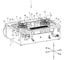
以下、本発明の実施形態について、図面を参照して説明する。以下説明は、図中に矢印で示す上下、左右、前後を使用する。なお、図1に示すテーブルこんろ1(以下、単に、こんろ1と称する。)は、テーブルこんろであるが、ビルトインこんろ等であってもよい。   Hereinafter, embodiments of the present invention will be described with reference to the drawings. In the following description, the top, bottom, left and right, front and back indicated by arrows in the figure are used. The table stove 1 shown in FIG. 1 (hereinafter simply referred to as the stove 1) is a table stove, but may be a built-in stove or the like.

図1および図2を参照して、こんろ1の構造について説明する。図1および図2に示すように、こんろ1は、器具本体を構成する筐体2と、トッププレート3を備える。筐体2は、金属製であって、上面に開口部(図示せず)を備えた略直方体状に形成されている。筐体2の内部には、左右一対のガスバーナ5,5が配置されている。トッププレート3は、板金をプレス加工することで形成される。トッププレート3の少なくとも上面には、煮こぼれした液体等による汚れの固着を防止するため、ホーローによるコーティングが施されている。トッププレート3は、筐体2上面の開口部を閉塞して、筐体2の上部に固定されている。トッププレート3には、左右一対の略円形のバーナ開口4,4が形成されており、トッププレート3が筐体2の上部に設置されることで、ガスバーナ5が筐体2側から上方に突出して、各バーナ開口4の中央に臨む。ガスバーナ5,5の各周囲には、五徳50,50がそれぞれ配置されている。五徳50,50の各上部には、鍋、フライパン等を含む調理器具等の被加熱物(図示せず)が載置される。   The structure of the stove 1 will be described with reference to FIGS. 1 and 2. As shown in FIGS. 1 and 2, the stove 1 includes a housing 2 and a top plate 3 that constitute an instrument body. The housing 2 is made of metal and is formed in a substantially rectangular parallelepiped shape having an opening (not shown) on the upper surface. A pair of left and right gas burners 5 and 5 are arranged inside the housing 2. The top plate 3 is formed by pressing a sheet metal. At least the upper surface of the top plate 3 is coated with enamel to prevent sticking of dirt due to spilled liquid or the like. The top plate 3 closes the opening on the upper surface of the housing 2 and is fixed to the upper portion of the housing 2. The top plate 3 is formed with a pair of left and right substantially circular burner openings 4 and 4, and the gas burner 5 protrudes upward from the housing 2 side when the top plate 3 is installed on the top of the housing 2. Facing the center of each burner opening 4. Five virtues 50 and 50 are respectively arranged around the gas burners 5 and 5. In each upper part of the virtues 50, 50, an object to be heated (not shown) such as a cooking utensil including a pan, a frying pan or the like is placed.

ガスバーナ5は、筐体2の内部に配置されたバーナ本体(図示せず)と、バーナ本体の上部に設置され、外周部に多数の炎口5Aが形成されたバーナヘッド5Bを備える。バーナヘッド5Bの中央には、被加熱物の温度を検知するための鍋センサ5Cが設けられている。鍋センサ5Cの筒体の内部には、図示しないサーミスタが格納されているので、鍋センサ5Cは、鍋底温度等、被加熱物の温度を検知できる。図2に示すように、バーナヘッド5Bの後方の炎口5A近傍には、放電による点火を行うための点火電極5Dと、火炎の有無を検知するための熱電対5Eとが設けられている。点火電極5Dと熱電対5Eとがバーナヘッド5Bの後方側に配置されることで、筐体2正面側からこんろ1を使用する使用者から、点火電極5Dと熱電対5Eが視認されにくくなる。このため、こんろ1の外観がすっきりとするので、こんろ1の美観が向上する。   The gas burner 5 includes a burner main body (not shown) disposed inside the housing 2 and a burner head 5B installed on the upper part of the burner main body and having a plurality of flame ports 5A formed on the outer periphery. In the center of the burner head 5B, a pan sensor 5C for detecting the temperature of the object to be heated is provided. Since a thermistor (not shown) is housed inside the cylinder of the pan sensor 5C, the pan sensor 5C can detect the temperature of the object to be heated, such as the pan bottom temperature. As shown in FIG. 2, an ignition electrode 5D for performing ignition by discharge and a thermocouple 5E for detecting the presence or absence of a flame are provided in the vicinity of the flame outlet 5A behind the burner head 5B. Since the ignition electrode 5D and the thermocouple 5E are arranged on the rear side of the burner head 5B, the ignition electrode 5D and the thermocouple 5E are not easily seen by the user who uses the stove 1 from the front side of the housing 2. . For this reason, since the appearance of the stove 1 is clean, the beauty of the stove 1 is improved.

また、図1に示すように、筐体2の正面中央には、グリル扉24が設けられている。グリル扉24の前面にはガラス窓部25が設けられている。こんろ1の使用者は、ガラス窓部25によって、筐体2の内部に設置されるグリル庫(図示せず)内部の被調理物の焼け具合等を視認できる。ガラス窓部25の下方には、取っ手26が前方に突出して設けられている。グリル扉24は、筐体2の前方に引き出し可能であり、こんろ1の使用者は、取っ手26を把持してグリル扉24を引き出すことで、グリル庫を開閉できる。トッププレート3の後方には、複数の排気孔を備える排気口カバー8が設置されている。排気口カバー8は、後述するグリル排気口7(図3参照)を上側から覆うカバー部材である。   As shown in FIG. 1, a grill door 24 is provided at the front center of the housing 2. A glass window 25 is provided on the front surface of the grill door 24. The user of the stove 1 can visually recognize the degree of baking of the cooking object inside the grill cabinet (not shown) installed inside the housing 2 through the glass window 25. A handle 26 is provided below the glass window 25 so as to protrude forward. The grill door 24 can be pulled out in front of the housing 2, and the user of the stove 1 can open and close the grill cabinet by holding the handle 26 and pulling out the grill door 24. An exhaust port cover 8 having a plurality of exhaust holes is installed behind the top plate 3. The exhaust port cover 8 is a cover member that covers a grill exhaust port 7 (see FIG. 3) described later from above.

グリル扉24の右側の領域には、点火スイッチ11,12、火力調節つまみ16,17等がそれぞれ設けられている。点火スイッチ11は、グリル扉24の右側に隣接して設けられ、右側のガスバーナ5の点火/消火の操作を行う。点火スイッチ11が押下操作されると、バーナ本体へ一次空気と燃料ガスが供給され、混合気となってバーナヘッド5Bの炎口5Aから流出する。同時に、筐体2の内部に設けられた図示しないコントローラが点火電極5Dを放電させて混合気に点火し、バーナヘッド5Bの外周部に火炎が形成される。また、ガスバーナ5が点火されている状態で点火スイッチ11が操作されると、ガスバーナ5は消火される。点火スイッチ12は、点火スイッチ11の右隣に設けられ、グリル庫内部に設けられた上バーナおよび下バーナ(図示せず)の点火/消火の操作を行う。   In the area on the right side of the grill door 24, ignition switches 11 and 12, heating power adjustment knobs 16 and 17 and the like are provided, respectively. The ignition switch 11 is provided adjacent to the right side of the grill door 24 and performs ignition / extinguishing operation of the right gas burner 5. When the ignition switch 11 is pressed, primary air and fuel gas are supplied to the burner body, and the mixture is mixed and flows out from the flame port 5A of the burner head 5B. At the same time, a controller (not shown) provided in the housing 2 discharges the ignition electrode 5D to ignite the air-fuel mixture, and a flame is formed on the outer periphery of the burner head 5B. Further, when the ignition switch 11 is operated with the gas burner 5 being ignited, the gas burner 5 is extinguished. The ignition switch 12 is provided on the right side of the ignition switch 11 and performs an ignition / extinguishing operation of an upper burner and a lower burner (not shown) provided inside the grill cabinet.

さらに、火力調節つまみ16は、点火スイッチ11の上方に設けられ、略左右方向におけるスライド操作によって、右側のガスバーナ5の火力調節ができる。火力調節つまみ17は、点火スイッチ12の上方に設けられ、上火用調整つまみ17Aと下火用調整つまみ17Bとを上下に備える。上火用調整つまみ17Aは、略左右方向におけるスライド操作によって、グリル庫の上バーナの火力調節ができる。下火用調整つまみ17Bは、略左右方向におけるスライド操作によって、グリル庫の下バーナの火力調節ができる。   Further, the heating power adjustment knob 16 is provided above the ignition switch 11 and can adjust the heating power of the right gas burner 5 by a sliding operation in a substantially left-right direction. The thermal power adjustment knob 17 is provided above the ignition switch 12, and includes an upper fire adjustment knob 17A and a lower fire adjustment knob 17B. The upper heating adjustment knob 17A can adjust the heating power of the upper burner of the grill cabinet by a sliding operation in a substantially horizontal direction. The lower heating adjustment knob 17B can adjust the heating power of the lower burner of the grill cabinet by a sliding operation in a substantially horizontal direction.

一方、グリル扉24の左側の領域には、点火スイッチ13、火力調節つまみ18、電池ケース14等がそれぞれ設けられている。点火スイッチ13は、グリル扉24の左側に隣接して設けられ、左側のガスバーナ5の点火/消火の操作を行う。火力調節つまみ18は、点火スイッチ13の上方に設けられ、略左右方向におけるスライド操作によって、左側のガスバーナ5の火力調節ができる。電池ケース14は、点火スイッチ13の左隣に設けられ、こんろ1の電源として、例えば二つの乾電池(図示せず)を格納する。   On the other hand, an ignition switch 13, a heating power adjustment knob 18, a battery case 14, and the like are provided in the left region of the grill door 24. The ignition switch 13 is provided adjacent to the left side of the grill door 24 and performs ignition / extinguishing operation of the left gas burner 5. The thermal power adjustment knob 18 is provided above the ignition switch 13 and can adjust the thermal power of the left gas burner 5 by a sliding operation in a substantially horizontal direction. The battery case 14 is provided on the left side of the ignition switch 13 and stores, for example, two dry batteries (not shown) as the power source of the stove 1.

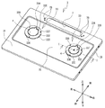
図3から図5を参照して、トッププレート3およびトッププレート3におけるバーナ開口4,4の周辺部の構造について説明する。図3に示すように、トッププレート3は、筐体2の上面開口部に対応する大きさの矩形状に形成されている。トッププレート3の上面31における後方には、左右に延びる略長方形状の孔部であるグリル排気口7が設けられている。グリル排気口7は、前述のグリル庫と連通して、グリル庫内部の排気を行う。また、グリル排気口7の左右の両側には、排気口カバー8を位置決めするための複数の孔部7Bが設けられている。   With reference to FIGS. 3 to 5, the structure of the peripheral portion of the top plate 3 and the burner openings 4 and 4 in the top plate 3 will be described. As shown in FIG. 3, the top plate 3 is formed in a rectangular shape having a size corresponding to the upper surface opening of the housing 2. On the rear side of the top surface 31 of the top plate 3, there is provided a grill exhaust port 7 that is a substantially rectangular hole extending left and right. The grill exhaust port 7 communicates with the aforementioned grill store and exhausts the inside of the grill store. A plurality of holes 7B for positioning the exhaust port cover 8 are provided on both the left and right sides of the grill exhaust port 7.

トッププレート3の外縁には、上面31から延設された板金が筐体2上部の外周に沿うように下方に折り返された外周部39が設けられている。トッププレート3は、筐体2の上部に配置された後、外周部39の複数の所定位置においてねじ止めされて筐体2に固定される。   On the outer edge of the top plate 3, an outer peripheral portion 39 is provided in which a sheet metal extended from the upper surface 31 is folded downward so as to follow the outer periphery of the upper portion of the housing 2. After the top plate 3 is disposed on the upper portion of the housing 2, the top plate 3 is fixed to the housing 2 by being screwed at a plurality of predetermined positions on the outer peripheral portion 39.

トッププレート3の上面31における略中央には、バーナ開口4,4を含み、上面31よりも一段下方に窪んだ部分である中央凹部32が設けられている。中央凹部32は、上面31よりも下方に設けられているので、例えばこんろ1の使用において生じた煮こぼれを受け止めることができる。これにより、こんろ1は、煮こぼれが上面31に向けて流出したり、上面31および外周部39を介して筐体2に向けて流出したりすることを防止できる。また、こんろ1は、筐体2に対するトッププレート3の固定のためのねじ止め部分を、トッププレート3の上面31および中央凹部32に設けていないので、上側から見たトッププレート3の美観が保たれる。また、こんろ1は、煮こぼれを直接に受けにくい外周部39にねじ止め部分を設けることで、ねじ孔の隙間を介して浸入した煮こぼれ等の液体が、トッププレート3の下面および筐体2の内部に汚れや錆等を引き起こす可能性を低減できる。   Near the center of the upper surface 31 of the top plate 3, there is provided a central recess 32 that includes the burner openings 4 and 4 and is recessed one step below the upper surface 31. Since the center recessed part 32 is provided below the upper surface 31, it can catch the spillage which arises, for example in use of the stove 1. FIG. Thereby, the stove 1 can prevent the spill from flowing out toward the upper surface 31 or outflowing toward the housing 2 through the upper surface 31 and the outer peripheral portion 39. Moreover, since the stove 1 is not provided with the screwing part for fixing the top plate 3 with respect to the housing | casing 2 in the upper surface 31 and the center recessed part 32 of the top plate 3, the aesthetics of the top plate 3 seen from the upper side are provided. Kept. In addition, the stove 1 is provided with a screw-fastening portion on the outer peripheral portion 39 that is not easily subjected to spillage, so that liquid such as spillage that has entered through the gaps in the screw holes can be removed from the bottom surface of the top plate 3 and the housing. The possibility of causing dirt or rust in the interior of 2 can be reduced.

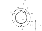
図3に示すように、中央凹部32において、バーナ開口4,4およびその周辺部は、それぞれ同じ構成を備える。バーナ開口4は、略円孔である。バーナ開口4の周縁部には、五徳装着部33が設けられている。五徳装着部33は、トッププレート3に五徳50を配置するために設けられる部位である。また、五徳装着部33は、バーナ開口4の周囲を上方から覆うことで、煮こぼれがバーナ開口4とガスバーナ5との間の隙間から筐体2内へ浸入することを防止している。本実施形態では、五徳装着部33は、プレス加工によってトッププレート3に一体に成型されている。   As shown in FIG. 3, in the central recess 32, the burner openings 4, 4 and the periphery thereof have the same configuration. The burner opening 4 is a substantially circular hole. On the peripheral edge of the burner opening 4, a five virtue mounting portion 33 is provided. The virtues mounting part 33 is a part provided for arranging the virtues 50 on the top plate 3. In addition, the five virtue mounting portions 33 cover the periphery of the burner opening 4 from above, thereby preventing the boiling from entering the housing 2 through the gap between the burner opening 4 and the gas burner 5. In the present embodiment, the five virtue mounting portions 33 are formed integrally with the top plate 3 by pressing.

五徳装着部33は、円環部332、接続部333、電極挿通部334、熱電対挿通部335、凹部336,337,338を備える。円環部332は、中央凹部32に対して上方に隆起してバーナ開口4の周縁部を取り囲む円環状の部分である。接続部333は、中央凹部32と円環部332とを接続する部分である。接続部333の外周部に、後述する五徳リング51(図6参照)が装着される。   The five virtue mounting part 33 includes an annular part 332, a connection part 333, an electrode insertion part 334, a thermocouple insertion part 335, and recesses 336, 337 and 338. The annular portion 332 is an annular portion that protrudes upward with respect to the central concave portion 32 and surrounds the peripheral portion of the burner opening 4. The connection portion 333 is a portion that connects the central recess 32 and the annular portion 332. A virtuosity ring 51 (see FIG. 6), which will be described later, is attached to the outer periphery of the connection portion 333.

電極挿通部334は、円環部332の後側において、点火電極5Dを円環部332の下面側から上面側へ挿通させるための部位である。電極挿通部334は、円環部332において、点火電極5Dの設置位置に対応する位置に配置されている。熱電対挿通部335は、円環部332における電極挿通部334の右側において、熱電対5Eを円環部332の下面側から上面側へ挿通させるための部位である。熱電対挿通部335は、円環部332において、熱電対5Eの設置位置に対応する位置に配置されている。本実施形態では、電極挿通部334および熱電対挿通部335は、ともにバーナ開口4に連続した凹みとして設けられている。詳細には、電極挿通部334および熱電対挿通部335は、バーナ開口4の後側の点火電極5Dおよび熱電対5Eに対応する部分が、円環部332の後側および右斜め後側のそれぞれに向けて広げられた形状で設けられている。   The electrode insertion part 334 is a part for allowing the ignition electrode 5D to be inserted from the lower surface side to the upper surface side of the annular part 332 on the rear side of the annular part 332. The electrode insertion part 334 is arranged at a position corresponding to the installation position of the ignition electrode 5D in the annular part 332. The thermocouple insertion part 335 is a part for allowing the thermocouple 5E to be inserted from the lower surface side to the upper surface side of the annular part 332 on the right side of the electrode insertion part 334 in the annular part 332. The thermocouple insertion part 335 is arranged at a position corresponding to the installation position of the thermocouple 5E in the annular part 332. In the present embodiment, the electrode insertion part 334 and the thermocouple insertion part 335 are both provided as dents continuous to the burner opening 4. In detail, the electrode insertion part 334 and the thermocouple insertion part 335 are respectively provided on the rear side of the annular part 332 and the diagonally right rear side of the annular part 332 respectively, corresponding to the ignition electrode 5D and the thermocouple 5E on the rear side of the burner opening 4. It is provided in a shape that is widened toward the front.

凹部336,337,338は、接続部333の外側に嵌め合わされる五徳リング51に設けられている後述の三つの突起部6(図7参照)のそれぞれを受け入れて、五徳装着部33に対して五徳50を位置決めするための部位である。図4に示すように、凹部336は、五徳装着部33の正面において、接続部333から円環部332の径方向内側へ向けて窪んだ平面視略U字形状に形成されている。凹部336の内側には、上下方向において円環部332と中央凹部32との間の位置に配置される段部336Aが設けられている。段部336Aの中央凹部32に対する高さは、後述する五徳50の突起部6の形状に対応した高さである(図7参照)。凹部337は、五徳装着部33において、凹部336からバーナ開口4の中心Pを中心として反時計回りに略120度回転した位置に設けられている。凹部337は、凹部336と同様に、接続部333から円環部332の径方向内側へ向けて窪んだ平面視略U字形状で形成されている。凹部338は、五徳装着部33において、凹部336から中心Pを中心として時計回りに略120度回転した位置に設けられている。凹部338は、凹部336,337と同様に、接続部333から円環部332の径方向内側へ向けて窪んだ平面視略U字形状で形成されている。凹部337,338の内側には、段部336Aと同様の段部337A,338Aがそれぞれ設けられている。   The recesses 336, 337, and 338 receive each of three protrusions 6 (see FIG. 7), which will be described later, provided on the Gotoku ring 51 that is fitted to the outside of the connection part 333, to the Gotoku mounting part 33. This is a part for positioning the virtues 50. As shown in FIG. 4, the concave portion 336 is formed in a substantially U shape in plan view that is recessed from the connection portion 333 toward the radially inner side of the annular portion 332 on the front surface of the virtually mounted portion 33. Inside the recess 336, a step 336A is provided that is disposed at a position between the annular portion 332 and the central recess 32 in the vertical direction. The height of the step 336A with respect to the central recess 32 is a height corresponding to the shape of the protrusion 6 of the virtues 50 described later (see FIG. 7). The concave portion 337 is provided at a position that is rotated approximately 120 degrees counterclockwise from the concave portion 336 around the center P of the burner opening 4 in the gort mounting portion 33. Similar to the recess 336, the recess 337 is formed in a substantially U shape in plan view that is recessed from the connection portion 333 toward the inside in the radial direction of the annular portion 332. The concave portion 338 is provided at a position rotated approximately 120 degrees clockwise from the concave portion 336 around the center P in the virtually mounted portion 33. Similar to the recesses 336 and 337, the recess 338 is formed in a substantially U shape in plan view that is recessed from the connection portion 333 toward the inside in the radial direction of the annular portion 332. Step portions 337A and 338A similar to the step portion 336A are provided inside the recesses 337 and 338, respectively.

こんろ1において、凹部337,338、電極挿通部334および熱電対挿通部335を含む五徳装着部33は、板金をプレス加工することで形成される。このため、仮に、電極挿通部334および熱電対挿通部335に近接して凹部337,338が設けられると、その部分において五徳装着部33の板金強度が低下しやすくなったり、プレス加工時において歪み等が生じやすくなったりする可能性がある。そこで、本実施形態では、凹部337,338のそれぞれが、円環部332に配置された電極挿通部334および熱電対挿通部335を互いに挟む位置に配置されている。こんろ1は、凹部337,338、電極挿通部334および熱電対挿通部335をこのようの配置することで、凹部337,338、電極挿通部334および熱電対挿通部335のそれぞれを離間させることができる。これにより、凹部337,338、電極挿通部334および熱電対挿通部335とのそれぞれが円環部332に形成されるためのスペースが十分に確保される。従って、凹部337,338、電極挿通部334および熱電対挿通部335を含んで成型される五徳装着部33の強度が低下しにくい。また、五徳装着部33の成型歪みの発生が低減される。特に、本実施形態では、五徳装着部33がトッププレート3とともに一体にプレス加工される。仮に五徳装着部33に成型歪みが発生したトッププレート3は、こんろ1に使用できない。こんろ1は、上記のようにして五徳装着部33の成型歪みの発生を低減できるので、トッププレート3の歩留りを向上させることができる。また、このような凹部337,338、電極挿通部334および熱電対挿通部335の配置の工夫により、五徳装着部33を大きくすることなく、凹部337,338、電極挿通部334および熱電対挿通部335のそれぞれを離間させることができる。このため、五徳装着部33を小型化できるので、こんろ1の美観が向上する。   In the stove 1, the five virtue mounting portions 33 including the concave portions 337, 338, the electrode insertion portion 334, and the thermocouple insertion portion 335 are formed by pressing a sheet metal. For this reason, if the concave portions 337 and 338 are provided in the vicinity of the electrode insertion portion 334 and the thermocouple insertion portion 335, the sheet metal strength of the virtues mounting portion 33 tends to be reduced at that portion, or distortion occurs during press working. Etc. may occur easily. Therefore, in the present embodiment, each of the concave portions 337 and 338 is disposed at a position sandwiching the electrode insertion portion 334 and the thermocouple insertion portion 335 disposed in the annular portion 332. In the stove 1, the recesses 337, 338, the electrode insertion part 334, and the thermocouple insertion part 335 are separated from each other by arranging the recesses 337, 338, the electrode insertion part 334, and the thermocouple insertion part 335 in this manner. Can do. Thereby, a sufficient space is secured for each of the recesses 337 and 338, the electrode insertion portion 334, and the thermocouple insertion portion 335 to be formed in the annular portion 332. Therefore, the strength of the five virtue mounting portion 33 that is molded including the concave portions 337 and 338, the electrode insertion portion 334, and the thermocouple insertion portion 335 is unlikely to decrease. Moreover, generation | occurrence | production of the molding distortion of the five virtue mounting part 33 is reduced. In particular, in this embodiment, the five virtue mounting portions 33 are integrally pressed together with the top plate 3. The top plate 3 in which molding distortion has occurred in the virtually mounted portion 33 cannot be used for the stove 1. Since the stove 1 can reduce the occurrence of molding distortion of the virtues mounting portion 33 as described above, the yield of the top plate 3 can be improved. Further, by contriving the arrangement of the concave portions 337, 338, the electrode insertion portion 334, and the thermocouple insertion portion 335, the concave portions 337, 338, the electrode insertion portion 334, and the thermocouple insertion portion without increasing the size of the five virtue mounting portions 33. Each of 335 can be spaced apart. For this reason, since the five virtue mounting part 33 can be reduced in size, the beauty | look of the stove 1 improves.

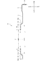
図5に示すように、バーナ開口4の縁部41の上側は、バーナ開口4の内側へ向けて上方にやや傾斜した形状に形成されている。また、バーナ開口4の縁部の板金端部は下方に折り曲げられている。円環部332は、バーナ開口4の周縁部に設けられ、バーナ開口4の縁部41の下端部からバーナ開口4の径方向外側へ向けて広がる平面部である。接続部333は、中央凹部32から立ち上がるとともに、上部において円環部332の外周縁部に接続する。接続部333のうち中央凹部32から立ち上がる部分333Bは、所定の曲率半径で円弧状に形成され、中央凹部32と接続部333とを滑らかに接続している。接続部333のうち円環部332に接続する部分333Aは、部分333Bの曲率半径よりも大きな所定の曲率半径で円弧状に形成され、上方に湾曲している。このため、接続部333のいずれの部分も、円環部332よりも下方に位置する。   As shown in FIG. 5, the upper side of the edge 41 of the burner opening 4 is formed in a shape slightly inclined upward toward the inside of the burner opening 4. Further, the end of the sheet metal at the edge of the burner opening 4 is bent downward. The annular portion 332 is a flat portion that is provided at the peripheral edge of the burner opening 4 and extends from the lower end of the edge 41 of the burner opening 4 toward the radially outer side of the burner opening 4. The connection portion 333 rises from the central recess 32 and is connected to the outer peripheral edge portion of the annular portion 332 at the upper portion. A portion 333 </ b> B rising from the central recess 32 of the connection portion 333 is formed in an arc shape with a predetermined curvature radius, and smoothly connects the central recess 32 and the connection portion 333. A portion 333A connected to the annular portion 332 of the connecting portion 333 is formed in an arc shape with a predetermined radius of curvature larger than the radius of curvature of the portion 333B, and is curved upward. For this reason, any part of the connection part 333 is located below the annular part 332.

このように、円環部332は、バーナ開口4の縁部41から、接続部333の部分333Aに接続する位置までの領域である。ここで、バーナ開口4の中心Pから、円環部332と接続部333との境界である円環部332の外周縁部までの距離をL1とする。   Thus, the annular portion 332 is a region from the edge 41 of the burner opening 4 to the position where it is connected to the portion 333A of the connecting portion 333. Here, the distance from the center P of the burner opening 4 to the outer peripheral edge of the annular portion 332 that is the boundary between the annular portion 332 and the connecting portion 333 is defined as L1.

図6から図8を参照して、五徳50の構造について説明する。図6に示すように、五徳50は、五徳リング51、三つの五徳爪52、三つの五徳爪53を主に備える。五徳リング51は、耐熱性を有する金属線材による円環形状であり、五徳50の基部をなす。五徳リング51は、五徳50をトッププレート3上に載置するときに、接続部333の外周部を囲むようにして五徳装着部33に装着される部分である。   The structure of the virtues 50 will be described with reference to FIGS. As shown in FIG. 6, the five virtues 50 mainly include a five virtue ring 51, three five virtue claws 52, and three five virtue claws 53. The Gotoku ring 51 has an annular shape made of a heat-resistant metal wire, and forms the base of the Gotoku 50. The virtuosity ring 51 is a part that is attached to the virtues mounting part 33 so as to surround the outer periphery of the connection part 333 when the virtues 50 are placed on the top plate 3.

三つの五徳爪52および三つの五徳爪53は、五徳リング51において周方向に所定間隔を置いて等間隔に配置される、耐熱性を有する金属製である。三つの五徳爪52および三つの五徳爪53は、五徳リング51に立設されて、五徳50に載置される被加熱物を下側において支持する。五徳爪52と五徳爪53とは、五徳リング51に対して周方向に交互に配置されている。一つの五徳爪52と他の五徳爪52との間隔は、五徳リング51の周方向に互いに120度間隔である。また、一つの五徳爪53と他の五徳爪53との間隔は、五徳リング51の周方向に互いに120度間隔である。このため、一つの五徳爪52と隣り合う他の五徳爪53との間隔は、五徳リング51の周方向に互いに60度間隔である。これらの三つの五徳爪52および三つの五徳爪53のそれぞれは、平面視において五徳リング51の中心Q側から径方向外側に向けて突出した放射状に配置されている。五徳爪52と五徳爪53とは、五徳爪52および五徳爪53が五徳リング51に対して取り付けられる部位の形状が互いに異なるが、その他の部分は同一の形状を有している。   The three five virtue claws 52 and the three five virtue claws 53 are made of a metal having heat resistance and arranged at equal intervals in the circumferential direction in the five virtue rings 51. The three five virtue claws 52 and the three five virtue claws 53 are erected on the five virtue ring 51 and support the heated object placed on the five virtues 50 on the lower side. The five virtue claws 52 and the five virtue claws 53 are alternately arranged in the circumferential direction with respect to the five virtue rings 51. The interval between one virtuosity claw 52 and another virtuosity claw 52 is 120 degrees apart from each other in the circumferential direction of the virtuosity ring 51. Further, the interval between one virtuosity claw 53 and another virtuosity claw 53 is 120 degrees apart from each other in the circumferential direction of the virtuosity ring 51. For this reason, the interval between one virtuosity claw 52 and another adjacent virtuosity claw 53 is 60 degrees apart from each other in the circumferential direction of the virtuosity ring 51. Each of the three virtuosity claw 52 and the three virtuosity claw 53 is disposed radially so as to project radially outward from the center Q side of the virtuosity ring 51 in plan view. The five virtue claws 52 and the five virtue claws 53 are different from each other in the shape of the part where the five virtue claws 52 and the five virtue claws 53 are attached to the five virtue ring 51, but the other portions have the same shape.

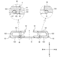
五徳爪52および五徳爪53の形状について詳細に説明する。図7に示すように、五徳爪52および五徳爪53は、ともに、正面視において五徳リング51の内側に向けて開口する略U字形状である。五徳爪52は、下アーム部523、上アーム部521および屈曲部522を備える。下アーム部523は、五徳爪52の下部において、五徳リング51の外周部から五徳リング51の径方向外側に向けて延びる部分である。屈曲部522は、五徳リング51の径方向外側に向けて屈曲した形状を有し、五徳リング51の径方向外側の位置において下アーム部523に接続して上方に延びる部分である。上アーム部521は、屈曲部522の上部に接続して五徳リング51の径方向外側から五徳リング51の中心Qに向けて延び、五徳50に載置される被加熱物を下側から支持する部分である。   The shapes of the five virtue claws 52 and the five virtue claws 53 will be described in detail. As shown in FIG. 7, the five virtue claws 52 and the five virtue claws 53 are both substantially U-shaped and open toward the inside of the five virtue rings 51 in a front view. The five virtue claws 52 include a lower arm portion 523, an upper arm portion 521, and a bent portion 522. The lower arm portion 523 is a portion that extends from the outer peripheral portion of the virtually ring 51 toward the radially outer side of the virtually ring 51 in the lower portion of the virtuosity claw 52. The bent portion 522 has a shape bent toward the radially outer side of the virtually ring 51, and is a portion that extends upward by connecting to the lower arm portion 523 at a radially outer position of the virtually ring 51. The upper arm portion 521 is connected to the upper portion of the bent portion 522 and extends from the radially outer side of the virtually ring 51 toward the center Q of the virtually ring 51 to support the object to be heated placed on the virtues 50 from below. Part.

五徳爪53は、五徳爪52と同様に、下アーム部533、屈曲部532および上アーム部531を備える。五徳爪52の上アーム部521および屈曲部522は、五徳爪53の上アーム部531および屈曲部532のそれぞれと同一形状である。五徳爪52の下アーム部523と、五徳爪53の下アーム部533とは、五徳リング51の径方向内側の端部の形状が互いに異なる。   The virtuosity claw 53 includes a lower arm portion 533, a bent portion 532, and an upper arm portion 531, similar to the virtuosity claw 52. The upper arm portion 521 and the bent portion 522 of the virtuosity claw 52 have the same shape as the upper arm portion 531 and the bent portion 532 of the virtuosity claw 53, respectively. The lower arm portion 523 of the virtuosity claw 52 and the lower arm portion 533 of the virtuosity claw 53 are different from each other in the shape of the radially inner end of the virtuosity ring 51.

図7のW1領域内に示すように、五徳爪52の下アーム部523における五徳リング51の径方向内側の端部には、突起部6が形成されている。突起部6は、下アーム部523が五徳リング51に取り付けられる位置に対応する五徳リング51の内縁部511から五徳リング51の径方向内側に向けて突出する部位である。本実施形態では、下アーム部523における五徳リング51の径方向内側の端部が、五徳リング51の内縁部511から五徳リング51の径方向内側に向けて延設されることで、突起部6が形成される。突起部6は、五徳リング51が五徳装着部33に装着されたときに、前述の五徳装着部33に設けられている凹部336,337,338に受け入れられる。これにより、五徳装着部33に装着された五徳50は、五徳装着部33に対して回転しないように固定される。
回り止めされる。
As shown in the W1 region of FIG. 7, a protruding portion 6 is formed at the radially inner end of the virtually ring 51 in the lower arm portion 523 of the virtuous claw 52. The protruding portion 6 is a portion that protrudes radially inward from the inner edge portion 511 of the virtually ring 51 corresponding to the position where the lower arm portion 523 is attached to the virtually ring 51. In the present embodiment, the radially inner end portion of the virtually ring 51 in the lower arm portion 523 is extended from the inner edge portion 511 of the virtually ring 51 toward the radially inner side of the virtually ring 51, whereby the protruding portion 6. Is formed. The protrusion 6 is received in the recesses 336, 337, and 338 provided in the aforementioned virtuosity mounting portion 33 when the virtuosity ring 51 is attached to the virtuosity mounting portion 33. Thereby, the virtues 50 attached to the virtues mounting part 33 are fixed so as not to rotate with respect to the virtues mounting part 33.
It is prevented from rotating.

突起部6は、上突出部61と下突出部62とを備える。上突出部61は、突起部6のうち最も五徳リング51の径方向内側に向けて突出する部位であり、突起部6の上部に設けられている。五徳50が五徳装着部33に対して装着された場合の中央凹部32から上突出部61の下端部611までの高さは、中央凹部32に対する凹部336,337,338の段部336A,337A,338Aの高さに対応している。このため、凹部336,337,338に受け入れられた突起部6は、段部336A,337A,338Aのそれぞれの上側に、上突出部61の下端部611を配置させる。上突出部61の五徳リング51の径方向内側の端部は、所定の曲率半径の円弧状に形成されている。このため、上突出部61は、凹部336,337,338の内部を傷めにくい。   The protrusion 6 includes an upper protrusion 61 and a lower protrusion 62. The upper protruding portion 61 is a portion that protrudes most radially inward of the virtually ring 51 in the protruding portion 6, and is provided on the upper portion of the protruding portion 6. The height from the central recess 32 to the lower end 611 of the upper protrusion 61 when the virtues 50 are attached to the virtues mounting portion 33 is the step portions 336A, 337A of the recesses 336, 337, 338 with respect to the central recess 32. This corresponds to a height of 338A. For this reason, the protrusion 6 received in the recesses 336, 337, and 338 has the lower end 611 of the upper protrusion 61 disposed on the upper side of each of the step portions 336A, 337A, and 338A. An end portion on the radially inner side of the virtually ring 51 of the upper protruding portion 61 is formed in an arc shape having a predetermined radius of curvature. For this reason, the upper protrusion part 61 is hard to damage the inside of the recessed part 336,337,338.

下突出部62は、突起部6のうち上突出部61に次いで五徳リング51の径方向内側に向けて突出する部位であり、突起部6の下部に設けられている。下突出部62は、上突出部61の下側において、五徳リング51の内縁部511から五徳リング51の径方向内側に向けて突出している。突起部6が凹部336,337,338に受け入れられたときに、下突出部62における五徳リング51の径方向内側の端部である内端部621は、凹部336,337,338の段部336A,337A,338Aよりも外側の位置に配置される。内端部621は、下突出部62において最も五徳リング51の径方向内側に向けて突出する部位である。下突出部62の下側の端部である下端部622は、五徳リング51の下縁部の僅かに下方に配置される。本実施形態では、五徳リング51において三つの下端部622が配置されるので、五徳リング51が五徳装着部33に装着された場合、五徳50は三つの下端部622を支点として中央凹部32において安定して載置される。内端部621と下端部622とのなす角部は、上突出部61の端部と同様に所定の曲率半径の円弧状に形成されているので、凹部336,337,338の内部および凹部336,337,338に対応する位置の中央凹部32の上面を傷めにくい。図8に示すように、五徳リング51の中心Qから下突出部62の内端部621までの距離をL2とする。   The lower projecting portion 62 is a portion of the projecting portion 6 that projects toward the radially inner side of the Gotoku ring 51 after the upper projecting portion 61, and is provided at the lower portion of the projecting portion 6. The lower protrusion 62 protrudes from the inner edge 511 of the virtually ring 51 toward the radially inner side of the virtually ring 51 on the lower side of the upper protrusion 61. When the protrusion 6 is received in the recesses 336, 337, and 338, the inner end 621 that is the radially inner end of the gort ring 51 in the lower protrusion 62 is the step 336 A of the recesses 336, 337, and 338. , 337A, 338A. The inner end portion 621 is a portion that protrudes most radially inward of the virtually ring 51 in the lower protruding portion 62. A lower end 622, which is the lower end of the lower protrusion 62, is disposed slightly below the lower edge of the virtually ring 51. In the present embodiment, since the three lower end portions 622 are arranged in the five virtue ring 51, when the five virtue ring 51 is mounted on the five virtue mounting portion 33, the five virtues 50 are stable in the central recess 32 with the three lower end portions 622 as fulcrums. And placed. The corner portion formed by the inner end portion 621 and the lower end portion 622 is formed in an arc shape having a predetermined radius of curvature similarly to the end portion of the upper projecting portion 61, so that the inside of the concave portions 336, 337, 338 and the concave portion 336 are formed. , 337, 338 are difficult to damage the upper surface of the central concave portion 32 at the positions corresponding to. As shown in FIG. 8, the distance from the center Q of the virtually ring 51 to the inner end 621 of the lower protrusion 62 is L2.

一方、図7のW2領域内に示すように、五徳爪53の下アーム部533おける五徳リング51の径方向内側の端部には、突起部6に相当する五徳リング51の内周縁から五徳リング51の径方向内側に向けて突出する部位は設けられていない。即ち、三つの五徳爪52および三つの五徳爪53のうち、三つの五徳爪52に突起部6が設けられている。   On the other hand, as shown in the W2 region of FIG. 7, the virtually ring 51 extends from the inner peripheral edge of the virtually ring 51 corresponding to the protrusion 6 to the radially inner end of the virtually ring 51 in the lower arm portion 533 of the virgin claw 53. The part which protrudes toward the radial inside of 51 is not provided. That is, of the three five virtue claws 52 and the three five virtue claws 53, the protrusions 6 are provided on the three five virtue claws 52.

図6に示すように、五徳リング51の中心Qを通過する仮想直線Sを左右方向に延ばして配置した場合、三つの五徳爪52のうち一つの五徳爪52は、五徳リング51において仮想直線Sよりも前側の部分に配置される。また、三つの五徳爪52のうち他の二つの五徳爪52は、五徳リング51において仮想直線Sよりも後側の部分に配置される。即ち、五徳リング51の内周縁に設けられる三つの突起部6のうち一つの突起部6は五徳リング51において仮想直線Sよりも前側の部分に、他の二つの突起部6は五徳リング51において仮想直線Sよりも後側の部分に、それぞれ配置される。このように、三つの五徳爪52が五徳リング51において仮想直線Sを挟んだ両側の部分に分散して配置される。このため、例えば突起部を有する五徳爪52が五徳リング51対して二つしか設けられない場合に比べて、五徳50が五徳装着部33に対して安定して位置決めされる。   As shown in FIG. 6, when the virtual straight line S passing through the center Q of the virtuosity ring 51 is arranged to extend in the left-right direction, one virtuosity claw 52 out of the three virtuosity claw 52 It is arrange | positioned in the front part rather than. The other two five virtue claws 52 out of the three five virtue claws 52 are arranged on the rear side of the virtual straight line S in the five virtue ring 51. That is, one of the three protrusions 6 provided on the inner peripheral edge of the gorgeous ring 51 has one protrusion 6 on the front side of the imaginary straight line S in the virtually ring 51 and the other two protrusions 6 on the virtually ring 51. They are arranged in the rear part of the virtual straight line S, respectively. In this way, the three virtuosity claws 52 are distributed and arranged on both sides of the imaginary straight line S in the virtuosity ring 51. For this reason, for example, the five virtues 50 are stably positioned with respect to the five virtue mounting portions 33 as compared with a case where only two five virtue claws 52 having protrusions are provided for the five virtue rings 51.

図9を参照して、五徳装着部33に対する五徳50の装着について説明する。図9に示すように、五徳リング51が接続部333の外周部に装着されることで、五徳50がトッププレート3の中央凹部32における五徳装着部33に装着される。五徳50が五徳装着部33に装着される際には、三つの五徳爪52のうち一つの五徳爪52が五徳装着部33の正面に配置される凹部336に対応する位置に配置される。また、三つの五徳爪52のうち他の二つの五徳爪52は、五徳装着部33の後面側に配置される凹部337,338に対応する位置に配置される。これにより、三つの五徳爪52それぞれの下アーム部523における五徳リング51の径方向内側の端部に形成された突起部6が、凹部336,337,338のそれぞれに受け入れられる。ここで、凹部336が五徳装着部33の正面側に配置されているので、凹部336に受け入れられる突起部6に対応する五徳爪52は、筐体2に対して正面側を向くように配置される。このため、こんろ1は、五徳50に載置される被加熱物を、筐体2の正面側に、より傾きにくくできる。   With reference to FIG. 9, the mounting of the virtues 50 on the virtues mounting portion 33 will be described. As shown in FIG. 9, the five virtue rings 51 are attached to the outer peripheral portion of the connection portion 333, so that the five virtues 50 are attached to the five virtue attaching portions 33 in the central recess 32 of the top plate 3. When the five virtues 50 are mounted on the five virtue mounting portions 33, one of the three virtue claws 52 is disposed at a position corresponding to the concave portion 336 disposed in front of the five virtue mounting portions 33. The other two five virtue claws 52 among the three virtue claws 52 are arranged at positions corresponding to the recesses 337 and 338 arranged on the rear surface side of the five virtue mounting portion 33. As a result, the protrusions 6 formed at the radially inner ends of the five virtue rings 51 in the lower arm portions 523 of the three five virtue claws 52 are received in the recesses 336, 337, and 338, respectively. Here, since the concave portion 336 is disposed on the front side of the virgin mounting portion 33, the five virtue claws 52 corresponding to the protrusions 6 received in the concave portion 336 are disposed so as to face the front side with respect to the housing 2. The For this reason, the stove 1 can make the to-be-heated object mounted in the virtues 50 less inclined to the front side of the housing 2.

本実施形態では、五徳50の三つの突起部6および凹部336,337,338が、五徳リング51および五徳装着部33のそれぞれにおいて周方向に120度間隔で配置されている。仮に、五徳リング51に対して突起部6を有する五徳爪52が二つ設けられる場合、突起部6の個数に対応して五徳装着部33に二つの凹部が設けられる。また、二つの突起部6および二つの凹部は、五徳リング51および五徳装着部33のそれぞれにおいて周方向に180度離間し、互いに対向する位置に設けられることがある。このような場合、五徳リング51を五徳リング51の周方向に180度回転させる毎に、二つの突起部6と二つの凹部とが対応する位置に配置されて、五徳装着部33に対して五徳リング51が装着される。これに対し、本実施形態では、五徳リング51は120度回転される毎に、五徳装着部33に対して五徳50に装着される。従って、五徳50が五徳装着部33に対して正しく装着されやすい。また、こんろ1の使い勝手が向上する。   In the present embodiment, the three protrusions 6 and the recesses 336, 337, and 338 of the five virtues 50 are disposed at 120 degree intervals in the circumferential direction in each of the five virtue rings 51 and the five virtue mounting portions 33. If two virtuosity claws 52 having the protrusions 6 are provided on the virtually ring 51, two recesses are provided in the virtuosity mounting part 33 corresponding to the number of the protrusions 6. In addition, the two protrusions 6 and the two recesses may be provided at positions facing each other at a distance of 180 degrees in the circumferential direction in each of the five virtue rings 51 and the five virtue mounting portions 33. In such a case, every time the virtuosity ring 51 is rotated 180 degrees in the circumferential direction of the virtuosity ring 51, the two protrusions 6 and the two recesses are arranged at corresponding positions, and A ring 51 is attached. On the other hand, in this embodiment, every time the virtue ring 51 is rotated 120 degrees, the virtue mounting portion 33 is attached to the virtue 50. Therefore, the virtues 50 are easily attached correctly to the virtues attaching part 33. In addition, the convenience of the stove 1 is improved.

図10および図11を参照して、五徳50が五徳装着部33に対して正しく装着されていない場合について説明する。図10に示すように、五徳50の五徳爪52の突起部6が五徳装着部33の正面に配置される凹部336に対して正しく位置決めされていない状態で、五徳装着部33に五徳50を装着しようとした場合、突起部6は、五徳装着部33の円環部332の上側に乗り上げ、五徳50が斜めに傾いた状態となる。このような、五徳50が五徳装着部33に対して正しく装着されていない状態を、以下、誤装着状態と称する。   With reference to FIG. 10 and FIG. 11, the case where the virtues 50 are not correctly mounted on the virtues mounting portion 33 will be described. As shown in FIG. 10, the virtues 50 are attached to the virtues mounting part 33 in a state where the protrusions 6 of the virtues claw 52 of the virtues 50 are not correctly positioned with respect to the recesses 336 arranged in front of the virtues mounting part 33. When trying to do so, the protruding portion 6 rides on the upper side of the annular portion 332 of the virtuosity mounting portion 33, and the virtues 50 are inclined. Such a state in which the virtues 50 are not correctly attached to the virtues attaching part 33 is hereinafter referred to as an erroneous attachment state.

前述のように、本実施形態では、五徳リング51において突起部6が三つ配置されるので、三つの突起部6それぞれの下端部622を支点として、五徳50を平面の上に載置することができる。ここで、バーナ開口4の中心Pから円環部332の外周縁部までの距離であるL1(図5参照)は、五徳リング51の中心Qから下突出部62の内端部621までの距離であるL2(図8参照)よりも短くされている。このため、五徳リング51を円環部332の上側に載置しようとする場合、五徳リング51の三つの下端部622のうち少なくとも一つの下端部622は円環部332の径方向外側に配置される。円環部332の径方向外側には、円環部332よりも下方に位置する接続部333が設けられている。このため、円環部332の径方向外側に配置された下端部622は、円環部332の径方向内側に配置された下端部622よりも下方に配置される。このため、五徳リング51は、円環部332の径方向外側に配置された下端部622を下側に向けて傾斜する。また、円環部332の径方向外側に配置された下端部622は、接続部333の上側に配置された後、接続部333の上面に沿って中央凹部32に向けて、さらに下方に移動しやすい。即ち、五徳50および五徳装着部33は、五徳装着部33の円環部332の上側に、五徳リング51の三つの下端部622の全てを同時に載置できないように構成されている。   As described above, in the present embodiment, since the three protrusions 6 are arranged in the virtually ring 51, the virtues 50 are placed on a plane with the lower ends 622 of the three protrusions 6 as fulcrums. Can do. Here, L1 (see FIG. 5), which is the distance from the center P of the burner opening 4 to the outer peripheral edge of the annular portion 332, is the distance from the center Q of the virtually ring 51 to the inner end 621 of the lower protrusion 62. It is shorter than L2 (see FIG. 8). For this reason, when it is intended to place the virtually ring 51 on the upper side of the annular portion 332, at least one lower end portion 622 of the three lower end portions 622 of the virtually ring 51 is disposed on the radially outer side of the annular portion 332. The A connecting portion 333 located below the annular portion 332 is provided on the radially outer side of the annular portion 332. For this reason, the lower end portion 622 disposed on the radially outer side of the annular portion 332 is disposed below the lower end portion 622 disposed on the radially inner side of the annular portion 332. For this reason, the Gotoku ring 51 is inclined with the lower end portion 622 disposed on the radially outer side of the annular portion 332 facing downward. In addition, the lower end portion 622 disposed on the radially outer side of the annular portion 332 moves further downward toward the central recess 32 along the upper surface of the connection portion 333 after being disposed on the upper side of the connection portion 333. Cheap. That is, the five virtue 50 and the five virtue mounting portions 33 are configured so that all three lower end portions 622 of the five virtue rings 51 cannot be placed on the upper side of the annular portion 332 of the five virtue mounting portions 33 at the same time.

例えば、突起部6が五徳装着部33の正面に配置される凹部336に正しく嵌め込まれず、凹部336近傍の円環部332に突起部6が乗り上げた誤装着状態の場合、図10および図11に示すように、五徳50は五徳装着部33に対して後方に傾斜した姿勢をとる。このような誤装着状態における五徳50の姿勢は、五徳50が五徳装着部33に対して正しく装着されている状態の姿勢(図9参照)とは異なる。なお、図10および図11は、誤装着状態の五徳50が五徳装着部33に対して後方に向けて傾斜する様子が示されているが、誤装着状態の五徳50は、この他、前方、左方、右方など、五徳装着部33に対して様々な方向に傾き得る。誤装着状態における五徳50が五徳装着部33に対していずれの方向に傾斜していても、こんろ1の使用者は、五徳50が誤装着状態にあることを一見して把握できる。こんろ1は、誤装着状態の五徳50が五徳装着部33に対して傾斜した姿勢をとるようにすることで、少なくとも五徳50の上に被加熱物を載置してこんろ1を使用する前までに、五徳50が誤装着状態にあることを、使用者にわかりやすく示すことができる。ひいては、五徳50が誤装着状態にあるまま、こんろ1が使用されることが防止される。   For example, in the case where the protruding portion 6 is not properly fitted into the recess 336 disposed in front of the virtually mounted portion 33 and the protruding portion 6 rides on the annular portion 332 in the vicinity of the recessed portion 336, FIG. 10 and FIG. As shown, the virtues 50 take a posture inclined backward with respect to the virtues mounting portion 33. The posture of the virtues 50 in such an erroneous attachment state is different from the posture (see FIG. 9) in a state where the virtues 50 are correctly attached to the virtues attachment portion 33. FIGS. 10 and 11 show a state in which the wrongly mounted virtues 50 are inclined rearward with respect to the virtually mounted portion 33. It can be tilted in various directions with respect to the five virtue mounting portions 33 such as left and right. Regardless of the direction in which the virtues 50 in the erroneous mounting state are inclined with respect to the morality mounting part 33, the user of the stove 1 can grasp at a glance that the virtues 50 are in the erroneous mounting state. The stove 1 uses the stove 1 by placing an object to be heated on at least the five virtues 50 by causing the misplaced virtues 50 to take a posture inclined with respect to the virtually wearing part 33. Previously, it can be shown to the user that the virtues 50 are in the wrong mounting state. As a result, it is prevented that the stove 1 is used while the five virtues 50 are in the wrong mounting state.

以上説明したように、本実施形態のこんろ1では、バーナ開口4の中心Pから円環部332の外周縁部までの距離であるL1が、五徳リング51の中心Qから突起部6のうち下突出部62の内端部621までの距離であるL2よりも短くされている。このため、五徳リング51の三つの突起部6が、五徳装着部33の凹部336,337,338のそれぞれに受け入れられず、五徳50が誤装着状態にある場合、五徳リング51の三つの下端部622の全てが円環部332の上側に載置されることがない。五徳リング51の三つの突起部6における下端部622のうち少なくとも一つの下端部622は、接続部333の上側に配置された後、接続部333の上面に沿って中央凹部32に向けて下方に移動する。この場合、五徳50は五徳装着部33に対していずれかの方向に傾斜した姿勢をとることになる。従って、こんろ1は、五徳50が誤装着状態にあることを、こんろ1の使用者に一見で把握させることができ、ひいては、五徳50が誤装着状態のまま、五徳50に調理容器等の被加熱物が載置されてこんろ1が使用されることを防止できる。   As described above, in the stove 1 of the present embodiment, L1 which is the distance from the center P of the burner opening 4 to the outer peripheral edge of the annular portion 332 is from the center Q of the virtually ring 51 to the protrusion 6. It is shorter than L2, which is the distance to the inner end 621 of the lower protrusion 62. For this reason, when the three protrusions 6 of the virtually ring 51 are not received in the recesses 336, 337, and 338 of the virtually mounted portion 33 and the virtually 50 is in an erroneous mounting state, the three lower end portions of the virtually ring 51 All of 622 is not placed on the upper side of the annular portion 332. At least one lower end 622 of the lower end portions 622 of the three protrusions 6 of the virtually ring 51 is disposed on the upper side of the connection portion 333, and then downwards toward the central recess 32 along the upper surface of the connection portion 333. Moving. In this case, the virtues 50 take a posture inclined in any direction with respect to the virtues mounting part 33. Accordingly, the stove 1 can cause the user of the stove 1 to grasp at a glance that the virtues 50 are in an erroneously attached state. As a result, the virtues 50 remain in the erroneously attached state and the virtues 50 are in a cooking container. It is possible to prevent the stove 1 from being used by placing the object to be heated.

こんろ1において、五徳リング51の内縁部511に三つの突起部6が設けられている。三つの突起部6ののうち一つの突起部6は、に対して、五徳リング51の中心Qを通過して左右方向に延びる仮想直線Sよりも、五徳リング51において前側の部分に配置される。また、三つの五徳爪52のうち他の二つの五徳爪52は、五徳リング51において仮想直線Sよりも後側の部分に配置される。三つの突起部6が、五徳リング51において仮想直線Sを挟んだ両側の部分に分散して配置されるので、例えば突起部を有する五徳爪52が五徳リング51に対して二つしか設けられない場合に比べて、五徳50が五徳装着部33に対して安定して位置決めされる。なお、このように五徳リング51に三つの突起部6が設けられることで、五徳リング51に対して突起部が二つしか設けられない従来例よりも、五徳50は三つの下端部622を支点として中央凹部32等の平面上に安定して載置される。この点、前述の距離L1が、同じく前述の距離L2よりも短くされているので、三つの下端部622うち少なくとも一つの下端部622は円環部332の上側に載置されることがなく、誤装着状態の五徳50は五徳装着部33に対して傾斜する。従って、こんろ1は、安定性の向上した五徳50を使用した場合にも、五徳50が誤装着状態にあることを使用者に一見で把握させることができる。   In the stove 1, three protrusions 6 are provided on the inner edge 511 of the virtually ring 51. One of the three protrusions 6 is disposed at the front portion of the virtually ring 51 with respect to the virtual straight line S that passes through the center Q of the virtually ring 51 and extends in the left-right direction. . The other two five virtue claws 52 out of the three five virtue claws 52 are arranged on the rear side of the virtual straight line S in the five virtue ring 51. Since the three protrusions 6 are distributed and arranged on both sides of the virtually ring 51 across the virtual straight line S, for example, only two virtues claw 52 having protrusions are provided on the virtually ring 51. Compared to the case, the virtues 50 are stably positioned with respect to the virtues mounting portion 33. In addition, by providing the three protrusions 6 on the Gotoku ring 51 in this way, the Gotoku 50 has three lower end parts 622 as fulcrums as compared with the conventional example in which only two protrusions are provided on the Gotoku ring 51. As described above, it is stably placed on a plane such as the central recess 32. In this respect, since the above-described distance L1 is also shorter than the above-described distance L2, at least one lower end portion 622 of the three lower end portions 622 is not placed on the upper side of the annular portion 332, The misplaced virtues 50 incline with respect to the virtues mounting portion 33. Therefore, the stove 1 can make a user grasp at a glance that the virtues 50 are in an erroneous mounting state even when the virtues 50 with improved stability are used.

こんろ1は、五徳リング51において、五徳リング51の周方向に60度間隔で交互に配置される三つの五徳爪52および三つの五徳爪53を備える。突起部6は、三つの五徳爪52のそれぞれの下アーム部523における五徳リング51の径方向内側の端部が、五徳リング51の内縁部511から五徳リング51の径方向内側に向けて延設されることで設けられる。即ち、三つの突起部6は、五徳リング51において五徳リング51の周方向に120度間隔で配置される三つの五徳爪52の五徳リング51に対する取付位置に対応して設けられる。このため、五徳リング51を120度回転させる毎に、五徳装着部33に対して五徳50を正しく装着できる。五徳装着部33に対して五徳50が正しく装着されやすいので、五徳50が誤装着状態になることが防止される。また、こんろ1の使い勝手が向上する。   The stove 1 is provided with three virtues claws 52 and three virtues claws 53 alternately arranged at intervals of 60 degrees in the circumferential direction of the virtuosity ring 51 in the virtuosity ring 51. The protrusion 6 has a radially inner end portion of the five virtue rings 51 in the lower arm portion 523 of each of the three virtue claws 52 extending from the inner edge portion 511 of the five virtue rings 51 toward the radially inner side of the five virtue rings 51. Is provided. That is, the three protrusions 6 are provided corresponding to the attachment positions of the three virtues claws 52 arranged at 120 degree intervals in the circumferential direction of the virtuosity ring 51 in the virtuosity ring 51. For this reason, every time the five virtue rings 51 are rotated 120 degrees, the five virtues 50 can be correctly attached to the five virtue mounting portions 33. Since the five virtues 50 are easily attached correctly to the five virtue wearing parts 33, the virtue 50 is prevented from being erroneously attached. In addition, the convenience of the stove 1 is improved.

凹部336は、五徳装着部33の正面側に配置される。このため、凹部336に受け入れられる突起部6に対応する五徳爪52は、筐体2に対して正面側を向くように配置される。従って、五徳50に載置される被加熱物が、筐体2の正面側に転倒することが防止される。また、点火電極5Dおよび熱電対5Eは、バーナヘッド5Bの後方の炎口5A近傍に配置される。このため、筐体2正面側からこんろ1を使用する使用者から点火電極5Dと熱電対5Eが視認されにくく、こんろ1の美観が向上する。点火電極5Dおよび熱電対5Eを円環部332の下面側から上面側へ挿通させる電極挿通部334および熱電対挿通部335は、円環部332において、点火電極5Dおよび熱電対5Eの設置位置に対応する位置に配置されている。凹部336,337,338は円環部332の周方向に120度間隔で配置されるが、このうち、凹部337,338は、円環部332において、電極挿通部334および熱電対挿通部335を互いに挟む位置に配置されている。このため、凹部337,338と電極挿通部334および熱電対挿通部335との間に所定の間隔が設けられる。これにより、凹部337,338と電極挿通部334および熱電対挿通部335が設けられる箇所における、板金のプレス代(しろ)が不足することが防止され、五徳装着部33の成型歪みの発生が低減される。五徳装着部33がトッププレート3とともに一体に成型される場合等には、トッププレート3の歩留りの向上に特に資する。また、このように凹部337,338、電極挿通部334および熱電対挿通部335の配置を工夫することで、五徳装着部33を大きくすることなく、五徳装着部33の成型歪みの発生を低減できる。従って、五徳装着部33は小型化され、こんろ1の美観が向上する。   The recess 336 is disposed on the front side of the virtues mounting portion 33. For this reason, the five virtue claws 52 corresponding to the protrusions 6 received in the recesses 336 are arranged so as to face the front side with respect to the housing 2. Accordingly, the object to be heated placed on the virtues 50 is prevented from falling to the front side of the housing 2. Further, the ignition electrode 5D and the thermocouple 5E are arranged in the vicinity of the flame outlet 5A behind the burner head 5B. For this reason, the ignition electrode 5D and the thermocouple 5E are hardly visually recognized by the user who uses the stove 1 from the front side of the housing 2, and the beauty of the stove 1 is improved. An electrode insertion portion 334 and a thermocouple insertion portion 335 that allow the ignition electrode 5D and the thermocouple 5E to be inserted from the lower surface side to the upper surface side of the annular portion 332 are located at the installation positions of the ignition electrode 5D and the thermocouple 5E in the annular portion 332. It is arranged at the corresponding position. The recesses 336, 337, and 338 are arranged at intervals of 120 degrees in the circumferential direction of the annular portion 332. Of these, the recesses 337 and 338 include the electrode insertion portion 334 and the thermocouple insertion portion 335 in the annular portion 332, respectively. It arrange | positions in the position which pinches | interposes mutually. For this reason, a predetermined space is provided between the recesses 337 and 338 and the electrode insertion part 334 and the thermocouple insertion part 335. Accordingly, it is possible to prevent the sheet metal press margin from being insufficient at the positions where the concave portions 337 and 338, the electrode insertion portion 334, and the thermocouple insertion portion 335 are provided, and the occurrence of molding distortion of the virtues mounting portion 33 is reduced. Is done. In the case where the five virtue mounting portions 33 are formed integrally with the top plate 3, it particularly contributes to the improvement of the yield of the top plate 3. Further, by devising the arrangement of the recesses 337 and 338, the electrode insertion portion 334, and the thermocouple insertion portion 335 in this way, it is possible to reduce the occurrence of molding distortion of the virtuosity mounting portion 33 without increasing the morality mounting portion 33. . Therefore, the five virtue mounting part 33 is miniaturized and the beauty of the stove 1 is improved.

本実施形態において、こんろ1が、本発明の「こんろ」に相当する。ガスバーナ5が、本発明の「バーナ」に相当する。筐体2が、本発明の「筐体」に相当する。バーナ開口4が、本発明の「バーナ開口」に相当する。トッププレート3が、本発明の「天板」に相当する。五徳装着部33が、本発明の「五徳装着部」に相当する。五徳50が、本発明の「五徳」に相当する。五徳リング51が、本発明の「五徳リング」に相当する。三つの五徳爪52および三つの五徳爪53が、本発明の「複数の五徳爪」に相当する。突起部6が、本発明の「突起部」に相当する。円環部332が、本発明の「円環部」に相当する。接続部333が、本発明の「接続部」に相当する。凹部336,337,338が、本発明の「凹部」に相当する。点火電極5Dが、本発明の「点火手段」に相当する。熱電対5Eが、本発明の「検知手段」に相当する。電極挿通部334および熱電対挿通部335が、本発明の「挿通部」に相当する。   In the present embodiment, the stove 1 corresponds to the “stove” of the present invention. The gas burner 5 corresponds to the “burner” of the present invention. The housing 2 corresponds to the “housing” of the present invention. The burner opening 4 corresponds to the “burner opening” of the present invention. The top plate 3 corresponds to the “top plate” of the present invention. The five virtue wearing part 33 corresponds to the “5 virtue wearing part” of the present invention. The 50 virtues correspond to the “5 virtues” of the present invention. The five virtue rings 51 correspond to the “five virtue rings” of the present invention. Three five virtue claws 52 and three five virtue claws 53 correspond to “a plurality of five virtue claws” of the present invention. The protrusion 6 corresponds to the “protrusion” of the present invention. The annular portion 332 corresponds to the “annular portion” of the present invention. The connection portion 333 corresponds to the “connection portion” of the present invention. The recesses 336, 337, and 338 correspond to the “recesses” of the present invention. The ignition electrode 5D corresponds to the “ignition means” of the present invention. The thermocouple 5E corresponds to the “detecting means” of the present invention. The electrode insertion part 334 and the thermocouple insertion part 335 correspond to the “insertion part” of the present invention.

なお、本発明は上記実施形態に限定されるものではなく、種々の変更が可能である。例えば、五徳装着部33に設けられる凹部336,337,338の形状は、上記実施形態のものに限られず、種々に変更できる。以下、本発明の変形例について説明する。   In addition, this invention is not limited to the said embodiment, A various change is possible. For example, the shapes of the recesses 336, 337, and 338 provided in the virtues mounting portion 33 are not limited to those of the above-described embodiment, and can be variously changed. Hereinafter, modifications of the present invention will be described.

図12を参照して、本発明の変形例について説明する。変形例として、上記実施形態の五徳装着部33において、凹部346,347,348が設けられた例について説明する。円環部332、接続部333、電極挿通部334、熱電対挿通部335については、上記実施形態と同様であるので、説明を省略する。図12に示すように、変形例における凹部346は、五徳装着部33の正面において、接続部333から円環部332の径方向内側へ向けて窪んだ形状で設けられている。凹部347,348のそれぞれは、凹部346からバーナ開口4の中心Pを中心として反時計回りおよび時計回りに略120度回転した位置において、接続部333から円環部332の径方向内側へ向けて窪んだ形状で、設けられている。凹部346,347,348はそれぞれ同様の形状を有しているので、凹部346に着目して説明する。   A modification of the present invention will be described with reference to FIG. As a modified example, an example in which the recesses 346, 347, and 348 are provided in the five virtue mounting portion 33 of the above embodiment will be described. Since the annular portion 332, the connection portion 333, the electrode insertion portion 334, and the thermocouple insertion portion 335 are the same as those in the above embodiment, the description thereof is omitted. As shown in FIG. 12, the recess 346 in the modified example is provided in a shape recessed from the connection portion 333 toward the inside in the radial direction of the annular portion 332 on the front surface of the virtually mounted portion 33. Each of the recesses 347 and 348 is directed from the connection portion 333 toward the radially inner side of the annular portion 332 at a position rotated approximately 120 degrees counterclockwise and clockwise about the center P of the burner opening 4 from the recess 346. It is provided in a recessed shape. Since the concave portions 346, 347, and 348 have the same shape, the description will be made by paying attention to the concave portion 346.

凹部346は、平面視で、円環部332の内側から接続部333の外側に向けて開口する穴部である。凹部346の円環部332の内側の端部から接続部333の外側の開口部に向けて、凹部346の形成する穴部は徐々に拡幅している。この場合、凹部346,347,348は、上記実施形態の凹部336,337,338よりも突起部6を受け入れやすくなるので、五徳50を五徳装着部33に対して容易に装着でき、こんろ1の使い勝手が向上する。また、凹部346,347,348の内部の清掃性が向上するので、こんろ1の使用者は、こんろ1を衛生的に使用できる。変形例において、凹部346,347,348が本発明の「凹部」に相当する。   The recess 346 is a hole that opens from the inside of the annular portion 332 toward the outside of the connection portion 333 in plan view. The hole formed by the recess 346 gradually widens from the inner end of the annular portion 332 of the recess 346 toward the opening outside the connection portion 333. In this case, the recesses 346, 347, and 348 can more easily receive the protrusions 6 than the recesses 336, 337, and 338 of the above-described embodiment. Improved usability. Moreover, since the cleanability inside the recesses 346, 347, and 348 is improved, the user of the stove 1 can use the stove 1 in a sanitary manner. In the modification, the recesses 346, 347, and 348 correspond to the “recesses” of the present invention.

なお、本発明は、上記の実施形態および変形例に限定されるものではなく、種々の変更が可能である。上記実施形態では、五徳装着部33は、トッププレート3と一体に成型されているが、これに限られず、五徳装着部33がトッププレート3とは別体に構成されていてもよい。   In addition, this invention is not limited to said embodiment and modification, A various change is possible. In the above embodiment, the five virtue mounting part 33 is formed integrally with the top plate 3, but the present invention is not limited to this, and the five virtue mounting part 33 may be configured separately from the top plate 3.

接続部333は、円環部332よりも下方に位置する部分であればよく、例えば、接続部333は、上下方向において円環部332と中央凹部32との間の位置において、円環部332から一段下がった段落ち部であってもよい。また、接続部333は、円環部332の外周縁部と中央凹部32とを接続する斜面部であってもよい。   The connecting portion 333 may be a portion positioned below the annular portion 332. For example, the connecting portion 333 is located at a position between the annular portion 332 and the central recess 32 in the vertical direction. It may be a stepped part that is lowered by one step. Further, the connecting portion 333 may be a slope portion connecting the outer peripheral edge portion of the annular portion 332 and the central recessed portion 32.

電極挿通部334および熱電対挿通部335は、ともにバーナ開口4に連続した凹みとして設けられていなくてもよく、例えば、バーナ開口4とは独立した孔部として円環部332における点火電極5Dおよび熱電対5Eの設置位置に対応する位置に配置されてもよい。   Both the electrode insertion part 334 and the thermocouple insertion part 335 may not be provided as a recess continuous to the burner opening 4. For example, the ignition electrode 5D and the ignition electrode 5D in the annular part 332 as a hole independent of the burner opening 4 You may arrange | position in the position corresponding to the installation position of the thermocouple 5E.

凹部336,337,338は、五徳装着部33において、必ずしも接続部333の外側から円環部332の内側へ向けて窪んだ形状で設けられていなくてもよい。例えば、凹部336,337,338の窪んだ形状が、接続部333のみに留まるものであってもよい。五徳50の突起部6の形状は、五徳50を五徳装着部33に対して位置決めするのに適した種々の形状を採用可能であるとともに、突起部6を受け入れる凹部336,337,338の形状も突起部6の形状に応じた種々の形状を採用可能である。   The recesses 336, 337, and 338 do not necessarily have to be provided in the Gotoku mounting portion 33 in a shape that is recessed from the outside of the connection portion 333 toward the inside of the annular portion 332. For example, the concave shape of the recesses 336, 337, and 338 may remain only at the connection portion 333. As the shape of the protrusion 6 of the virtues 50, various shapes suitable for positioning the virtues 50 with respect to the virtues mounting portion 33 can be adopted, and the shapes of the recesses 336, 337, 338 for receiving the protrusions 6 are also possible. Various shapes according to the shape of the protrusion 6 can be employed.

上記実施形態では、五徳爪52は突起部6を有し、五徳爪52は、五徳リング51に対して三つ設けられているが、五徳リング51は、五徳爪52を二つ備えてもよいし、四つ以上の五徳爪52を備えてもよい。この場合、五徳爪52の配置および個数に応じて、五徳装着部33に設ける凹部336,337,338の配置および個数を変更してもよい。   In the above embodiment, the five virtue claws 52 have the protrusions 6 and the three virtue claws 52 are provided with respect to the five virtue rings 51, but the five virtue rings 51 may include two five virtue claws 52. However, four or more five virtue claws 52 may be provided. In this case, the arrangement and number of the recesses 336, 337, and 338 provided in the virtuosity mounting portion 33 may be changed according to the arrangement and number of the virtuosity claws 52.

突起部6は、必ずしも五徳爪52の下アーム部523における五徳リング51の径方向内側の端部に設けられなくてもよい。例えば、突起部6と同様の用途をなす突起等が、五徳爪52の五徳リング51に対する取付位置とは異なる位置において、五徳リング51の内縁部511から五徳リング51の径方向内側に向けて突出して設けられてもよい。また、このような突起等は、五徳リング51に二つ以上設けられていればよい。この場合、五徳リング51における突起等の配置および個数に応じて、五徳装着部33に設ける凹部336,337,338の配置および個数を変更してもよい。   The protrusion 6 does not necessarily have to be provided at the radially inner end of the virtuosity ring 51 in the lower arm 523 of the virtuosity claw 52. For example, a protrusion or the like having the same application as the protrusion 6 protrudes from the inner edge 511 of the virtually ring 51 toward the inner side in the radial direction of the virtually ring 51 at a position different from the attachment position of the virtuosity claw 52 to the virtually ring 51. May be provided. Further, it is sufficient that two or more such protrusions or the like are provided on the virtually ring 51. In this case, the arrangement and number of the recesses 336, 337, and 338 provided in the virtuosity mounting portion 33 may be changed according to the arrangement and number of protrusions and the like in the virtually ring 51.

ガスバーナ5に点火するための手段は、上記実施形態の点火電極5Dに限られず、燃料ガスを含む混合気に点火可能なヒータ等であってもよい。また、上記実施形態のこんろ1は、ガスバーナ5を備えるガスこんろであるが、例えば石油等の液体燃料を含むその他の燃料を用いる種々のこんろであってもよい。   The means for igniting the gas burner 5 is not limited to the ignition electrode 5D of the above embodiment, and may be a heater or the like that can ignite an air-fuel mixture containing fuel gas. Moreover, although the stove 1 of the said embodiment is a gas stove provided with the gas burner 5, the various stoves using other fuels including liquid fuels, such as petroleum, may be sufficient, for example.

1 こんろ
2 筐体
3 トッププレート
4 バーナ開口
5 ガスバーナ
5D 点火電極
5E 熱電対
6 突起部
32 中央凹部
33 五徳装着部
50 五徳
51 五徳リング
52,53 五徳爪
332 円環部
333 接続部
334 電極挿通部
335 熱電対挿通部
336,337,338,346,347,348 凹部
DESCRIPTION OF SYMBOLS 1 Stove 2 Case 3 Top plate 4 Burner opening 5 Gas burner 5D Ignition electrode 5E Thermocouple 6 Protrusion part 32 Central recessed part 33 Gotoku attachment part 50 Gotoku 51 Gotoku ring 52, 53 Gotoku nail 332 Ring part 333 Connection part 334 Insertion of electrode Portion 335 Thermocouple insertion portion 336, 337, 338, 346, 347, 348 Recess

Claims (3)

上部が開口されるとともに、内部にバーナが配置される筐体と、
前記バーナを挿通させるバーナ開口を有し、前記筐体の上部に配置される天板と、
前記天板における前記バーナ開口の周縁部に設けられた五徳装着部に装着され、前記バーナの上方において被加熱物を支持する五徳とを備えたこんろであって、
前記五徳は、
円環状の五徳リングと、
前記五徳リングにおいて周方向に60度間隔で配置され、且つ、前記五徳リングの径方向外側に突出して設けられる六つの五徳爪と、
前記六つの五徳爪のうち一つ置きに配置される三つの五徳爪が前記五徳リングに対して取り付けられる取付位置に対応する前記五徳リングの内縁部が、前記五徳リングの径方向内側に延ばされてなる三つの突起部とを備え、
三つの前記突起部のうち一つの前記突起部は、前記五徳リングにおいて前記五徳リングの中心を通過して延びる仮想直線に対して直交する方向の一方側の部分に配置され、
前記三つの突起部のうち他の二つの前記突起部は、前記五徳リングにおいて前記仮想直線に対して直交する方向の前記一方側とは反対側である他方側の部分に配置され、
前記五徳装着部は、前記天板の上面に対して上方に隆起して、前記バーナ開口を円環状に取り囲む円環部と、
前記円環部の外縁部と前記天板の上面とを接続し、前記円環部よりも下方に位置する接続部と、
前記接続部の所定位置に設けられ、前記突起部を受け入れるための凹部とを備え、
少なくとも、前記バーナ開口の中心から前記円環部の前記外縁部までの距離は、前記五徳リングの中心から前記突起部下端の内周端までの距離よりも短くされている
ことを特徴とするこんろ。
A housing in which an upper part is opened and a burner is disposed inside;
Having a burner opening through which the burner is inserted, and a top plate disposed on the top of the housing;
A stove provided with a virtues mounted on a peripheral portion of the burner opening in the top plate, and equipped with virtues that support an object to be heated above the burner,
The five virtues
With an annular five virtuosity ring,
Six virtuosity claws that are arranged at intervals of 60 degrees in the circumferential direction in the virtuosity ring, and are provided to protrude radially outward of the virtuosity ring,
An inner edge portion of the five virtue rings corresponding to a mounting position at which three of the six virtue claws arranged every other five virtue claws are attached to the five virtue rings extends radially inward of the five virtue rings. With three protrusions formed,
One of the three protrusions is disposed on a portion on one side in a direction perpendicular to a virtual straight line extending through the center of the five virtue ring in the five virtue ring,
Of the three protrusions, the other two protrusions are arranged on the other side of the Gotoku ring, which is opposite to the one side in the direction orthogonal to the virtual straight line,
The five virtue mounting portion is raised upward with respect to the upper surface of the top plate, and an annular portion surrounding the burner opening in an annular shape,
Connecting the outer edge portion of the annular portion and the top surface of the top plate, and a connecting portion located below the annular portion;
Provided at a predetermined position of the connecting portion, and a recess for receiving the protruding portion,
At least the distance from the center of the burner opening to the outer edge of the annular portion is shorter than the distance from the center of the virtually ring to the inner peripheral end of the lower end of the protrusion. B
前記筐体には、前記バーナに点火するための点火手段および前記バーナの燃焼状態を検知するための検知手段が、前記バーナの背面側に隣接して設けられ、
前記五徳装着部は、前記円環部において前記点火手段および前記検知手段が設けられる位置に対応して設けられ、前記点火手段および前記検知手段を前記円環部の下面側から上面側に挿通させるための挿通部を備え、
前記凹部は、前記接続部の正面側の位置、および前記接続部において前記挿通部を左右に互いに挟む位置に、周方向に120度間隔で設けられていることを特徴とする請求項に記載のこんろ。
The casing is provided with ignition means for igniting the burner and detection means for detecting the combustion state of the burner adjacent to the back side of the burner,
The five virtue mounting portions are provided corresponding to positions where the ignition means and the detection means are provided in the annular portion, and the ignition means and the detection means are inserted from the lower surface side to the upper surface side of the annular portion. With an insertion part for
The recess is located on the front side of the connecting portion, and according to claim 1, wherein at positions sandwiching together the insertion portion in the left and right at the connection portion, and being provided at 120 degree intervals in the circumferential direction The stove.
前記凹部は、前記円環部の内側から外側に向けて拡幅する扇状に形成されることを特徴とする請求項1または2に記載のこんろ。 The stove according to claim 1 or 2 , wherein the recess is formed in a fan shape that widens from the inside to the outside of the annular portion.
JP2015135186A 2015-07-06 2015-07-06 Stove Active JP6560916B2 (en)

Priority Applications (1)

Application Number Priority Date Filing Date Title
JP2015135186A JP6560916B2 (en) 2015-07-06 2015-07-06 Stove

Applications Claiming Priority (1)

Application Number Priority Date Filing Date Title
JP2015135186A JP6560916B2 (en) 2015-07-06 2015-07-06 Stove

Publications (2)

Publication Number Publication Date
JP2017015360A JP2017015360A (en) 2017-01-19
JP6560916B2 true JP6560916B2 (en) 2019-08-14

Family

ID=57828968

Family Applications (1)

Application Number Title Priority Date Filing Date
JP2015135186A Active JP6560916B2 (en) 2015-07-06 2015-07-06 Stove

Country Status (1)

Country Link
JP (1) JP6560916B2 (en)

Families Citing this family (1)

* Cited by examiner, † Cited by third party
Publication number Priority date Publication date Assignee Title
JP7222658B2 (en) * 2018-10-25 2023-02-15 株式会社ハーマン gas stove

Family Cites Families (6)

* Cited by examiner, † Cited by third party
Publication number Priority date Publication date Assignee Title
US4089321A (en) * 1976-02-06 1978-05-16 Ondrasik Ii Vladimir J Constraining grate
JP3785122B2 (en) * 2002-06-25 2006-06-14 リンナイ株式会社 Gas stove mounting structure
JP4344291B2 (en) * 2004-07-20 2009-10-14 株式会社ハーマンプロ Attachment structure of attached parts to gas stove burner
JP4448100B2 (en) * 2006-02-01 2010-04-07 リンナイ株式会社 Gas stove
JP4647040B2 (en) * 2010-10-01 2011-03-09 リンナイ株式会社 Gas stove
JP5438079B2 (en) * 2011-09-08 2014-03-12 リンナイ株式会社 Gas stove

Also Published As

Publication number Publication date
JP2017015360A (en) 2017-01-19

Similar Documents

Publication Publication Date Title
JP7189600B2 (en) gas cooker
JP2020065678A (en) Gas rice cooker
EP3640545B1 (en) Griddle device
EP2773905B1 (en) Gas burner, in particular for a cooking appliance
US20200217511A1 (en) Gas Cooktop and Grate for the Gas Cooktop
EP2806213A2 (en) Cooking appliance and burner
CN104970708A (en) Cooking appliance
JP4453907B2 (en) Gas stove
JP6560916B2 (en) Stove
EP3495738B1 (en) Cooking device
JP6071975B2 (en) Stove
JP6709614B2 (en) This time
JP6546478B2 (en) Hot pot
KR100938201B1 (en) A burner and cooker comprising the same
JP6712696B2 (en) This time
JP6125473B2 (en) Gas stove
JP6448086B2 (en) Gas stove
JP6457790B2 (en) Gas stove and virtues
JP2008021473A (en) Induction heating cooking oven
EP3795905A1 (en) Transparent oven bottom
JP6853070B2 (en) Cooking container for grill
JP6692540B2 (en) This time
JP2020065680A (en) Gas rice cooker
JP2022114306A (en) Gas stove and trivet used in the same
JP2022025628A (en) grill

Legal Events

Date Code Title Description
A621 Written request for application examination

Free format text: JAPANESE INTERMEDIATE CODE: A621

Effective date: 20180529

A977 Report on retrieval

Free format text: JAPANESE INTERMEDIATE CODE: A971007

Effective date: 20190306

A131 Notification of reasons for refusal

Free format text: JAPANESE INTERMEDIATE CODE: A131

Effective date: 20190312

A521 Written amendment

Free format text: JAPANESE INTERMEDIATE CODE: A523

Effective date: 20190401

TRDD Decision of grant or rejection written
A01 Written decision to grant a patent or to grant a registration (utility model)

Free format text: JAPANESE INTERMEDIATE CODE: A01

Effective date: 20190716

A61 First payment of annual fees (during grant procedure)

Free format text: JAPANESE INTERMEDIATE CODE: A61

Effective date: 20190722

R150 Certificate of patent or registration of utility model

Ref document number: 6560916

Country of ref document: JP

Free format text: JAPANESE INTERMEDIATE CODE: R150