JP6558080B2 - Column fixing device for partition panel - Google Patents

Column fixing device for partition panel Download PDF

Info

Publication number
JP6558080B2
JP6558080B2 JP2015110957A JP2015110957A JP6558080B2 JP 6558080 B2 JP6558080 B2 JP 6558080B2 JP 2015110957 A JP2015110957 A JP 2015110957A JP 2015110957 A JP2015110957 A JP 2015110957A JP 6558080 B2 JP6558080 B2 JP 6558080B2
Authority
JP
Japan
Prior art keywords
plate
ceiling
column
rail
fixing bracket
Prior art date
Legal status (The legal status is an assumption and is not a legal conclusion. Google has not performed a legal analysis and makes no representation as to the accuracy of the status listed.)
Active
Application number
JP2015110957A
Other languages
Japanese (ja)
Other versions
JP2016223174A (en
Inventor
達樹 川井
達樹 川井
内田 隆博
隆博 内田
Current Assignee (The listed assignees may be inaccurate. Google has not performed a legal analysis and makes no representation or warranty as to the accuracy of the list.)
Itoki Corp
Original Assignee
Itoki Corp
Priority date (The priority date is an assumption and is not a legal conclusion. Google has not performed a legal analysis and makes no representation as to the accuracy of the date listed.)
Filing date
Publication date
Application filed by Itoki Corp filed Critical Itoki Corp
Priority to JP2015110957A priority Critical patent/JP6558080B2/en
Publication of JP2016223174A publication Critical patent/JP2016223174A/en
Application granted granted Critical
Publication of JP6558080B2 publication Critical patent/JP6558080B2/en
Active legal-status Critical Current
Anticipated expiration legal-status Critical

Links

Images

Description

本発明は、間仕切パネルにおける支柱固定装置に係わり、更に詳しくは支柱の上端部を天レールあるいは天井に固定するための間仕切パネルにおける支柱固定装置に関するものである。   The present invention relates to a column fixing device in a partition panel, and more particularly to a column fixing device in a partition panel for fixing an upper end portion of a column to a ceiling rail or a ceiling.

従来から天井に取付けた天レールと床面に敷設した地レールとの間に所定間隔で支柱を立設し、両支柱に適宜な係止手段にて表裏両面にパネル板を係止して装着した間仕切パネルは各種提供されている。具体的には、前記支柱は下端に設けたアジャスターを上向き開放の断面略コ字形の前記地レール内に載支するとともに、該支柱の上端に設けた天固定金具を下方開放した断面略コ字形の前記天レールの内部で天井にネジ止め固定し、隣接する支柱間には下部に前記アジャスターを利用してパネル受け部材を架設するとともに、上下中間位置に単数又は複数の横桟を横設して隣接する支柱の間隔を一定に保持している。   Conventionally, support columns are erected at a predetermined interval between the ceiling rail mounted on the ceiling and the ground rail laid on the floor surface, and panel plates are mounted on both columns by using appropriate locking means. Various partition panels are provided. Specifically, the strut has an adjuster provided at the lower end mounted on the ground rail having an upwardly open cross-section and an open top fixing bracket provided at the upper end of the post, and is substantially U-shaped in cross section. The top rail is fixed to the ceiling with screws, and the panel receiving member is installed between adjacent struts using the adjuster at the bottom, and one or more horizontal rails are installed horizontally at the upper and lower intermediate positions. The distance between adjacent struts is kept constant.

特許文献1には、支柱の上端部に上下スライド可能に内嵌した天固定金具を、天レールの凹溝内に嵌挿して支柱を保持する構造が開示されている。ここで、前記支柱の上端は、立起状態で前記天レールの両垂下板の下端よりも高い位置に設定され、両側に前記天レールを受け入れる切欠部を設けた構造であり、前記支柱の前面板と前記天固定金具とで天レールの垂下板を内外から挟み込んで、支柱を保持するという構成である。従って、前記天固定金具が存在しなくても、支柱が面外方向に傾倒することはなかったが、支柱が長くなり、その取り回しに難があった。更に、天固定金具に天レール若しくは天井に固定するための構造がなかった。通常、前記天固定金具は、ネジによる突っ張りによって支柱内に圧接して上下動不能に固定するが、ネジが緩めば自重で下がり、支柱内に落ち込むという問題もある。   Patent Document 1 discloses a structure in which a top fixing bracket that is slidably fitted in the upper end portion of a support column is fitted into a recessed groove of the top rail to hold the support column. Here, the upper end of the support column is set to a position higher than the lower ends of both hanging plates of the ceiling rail in the upright state, and has a structure in which notches for receiving the ceiling rails are provided on both sides. The structure is such that the hanging plate of the top rail is sandwiched from inside and outside by the face plate and the top fixing bracket to hold the support column. Therefore, even if the ceiling fixing bracket is not present, the support column does not tilt in the out-of-plane direction, but the support column becomes long and difficult to handle. Furthermore, there was no structure for fixing the ceiling fixing bracket to the ceiling rail or the ceiling. Usually, the top fixing bracket is pressed against the inside of the support by tensioning with a screw and fixed so as not to move up and down. However, if the screw is loosened, there is a problem that it falls by its own weight and falls into the support.

一方、特許文献2には、支柱の上端部に嵌挿した天固定金具を、天レール内で天井にネジ止め固定するとともに、天固定金具を支柱の上端部に側方からネジ止めする構造が開示されているが、前記支柱の上端部も前記天レール内に収まる構造であり、前記同様に支柱が長くなり、その取り回しに難があった。   On the other hand, Patent Document 2 has a structure in which the top fixing bracket fitted to the upper end of the column is screwed and fixed to the ceiling in the ceiling rail, and the ceiling fixing bracket is screwed to the upper end of the column from the side. Although it is disclosed, the upper end portion of the support column has a structure that can be accommodated in the ceiling rail, and the support column becomes long similarly to the above, and it is difficult to handle the support column.

特許第4155239号公報Japanese Patent No. 4155239 特開2014−163168号公報JP 2014-163168 A

そこで、本発明が前述の状況に鑑み、解決しようとするところは、天レールと地レール間にパネル板を支持する支柱を立設し、該支柱の上端部に上下スライド可能に嵌挿した天固定金具で天レールあるいは天井に固定することが可能であり、側方からのネジの突っ張りによって天固定金具を上下動不能に固定する構造を備え、ネジが緩んでも天固定金具が支柱内に落ち込まず、また支柱の長さを抑制して取り回しを容易にした場合でも、支柱の面外方向への傾倒を抑制することが可能な間仕切パネルにおける支柱固定装置を提供する点にある。   Therefore, in view of the above-described situation, the present invention intends to solve the problem that a column supporting a panel plate is erected between the ceiling rail and the ground rail, and the column is slidably inserted into the upper end of the column so as to be vertically slidable. It can be fixed to the ceiling rail or ceiling with a fixing bracket, and it has a structure to fix the ceiling fixing bracket so that it cannot move up and down by stretching the screw from the side. Even if the screw is loosened, the ceiling fixing bracket falls into the column In addition, the present invention is to provide a column fixing device for a partition panel that can suppress tilting of the column in the out-of-plane direction even when the column is suppressed to facilitate handling.

本発明は、前述の課題解決のために、天レールと地レール間にパネル板を支持する支柱を立設し、該支柱の上端部に装着した天固定金具で天レールあるいは天井に固定する構造の間仕切パネルにおいて、前記天レールは下方開放した断面略コ字形であり、前記支柱の上端部に上下スライド可能に嵌挿した天固定金具を側方からネジによる突っ張りによって上下動不能に固定し、該天固定金具の上端に設けた固定片を天レールの天面板に接合してネジ止め固定可能な構造の支柱固定装置であって、前記天固定金具は、一側面となる連結板の両側から直角に前板と後板を折曲して平面視略コ字形とし、前記連結板の上端部の中央に切欠部を形成するとともに、該切欠部の両側に前記固定片を設け、更に前記前板と後板の上部に横幅を広くして前記支柱の上端に当止する幅広部を設けていることを特徴とする間仕切パネルにおける支柱固定装置を構成した(請求項1)。 In order to solve the above-mentioned problem, the present invention has a structure in which a column supporting a panel plate is erected between the ceiling rail and the ground rail, and is fixed to the ceiling rail or the ceiling with a ceiling fixing bracket attached to the upper end of the column. In the partition panel, the top rail has a substantially U-shaped cross section opened downward, and the top fixing bracket fitted to the upper end of the support column so as to be slidable up and down is fixed so that it cannot be moved up and down by stretching with a screw from the side, A column fixing device having a structure in which a fixing piece provided at an upper end of the ceiling fixing bracket can be fixed to a ceiling plate of a ceiling rail by screwing and fixing the ceiling fixing bracket from both sides of a connecting plate on one side. The front plate and the rear plate are bent at a right angle to form a substantially U shape in plan view, and a notch is formed at the center of the upper end of the connecting plate, the fixing pieces are provided on both sides of the notch, and the front It said widening the width at the top of the rear and plate plate To constitute a post anchoring device in partition panel, characterized in that is provided with a wide portion for abutting-stops to the upper end of the column (claim 1).

更に、前記支柱の上端は、立起状態において前記天レールの下端よりも低い位置になるように設定し、前記天固定金具の幅広部が前記支柱の上端に当接した状態でも、該天固定金具上部が前記天レールの下端よりも高い位置に保持されていることも好ましい(請求項)。 Furthermore, the upper end of the column is set to be lower than the lower end of the ceiling rail in the standing state, and the ceiling fixing is performed even when the wide part of the ceiling fixing bracket is in contact with the upper end of the column. it is also preferred that the metal top is held at a position higher than the lower end of the top rail (claim 2).

そして、前記天固定金具の固定片は、前記前板と後板の側縁よりも側方へ延び、その先端部には前記天レールあるいは天井にネジ止めするための通孔を形成してなることも好ましい(請求項)。 And the fixed piece of the top fixing bracket extends to the side from the side edges of the front plate and the rear plate, and a through hole for screwing to the top rail or the ceiling is formed at the tip thereof. It is also preferable (Claim 3 ).

以上にしてなる請求項1に係る発明の間仕切パネルにおける支柱固定装置は、天レールと地レール間にパネル板を支持する支柱を立設し、該支柱の上端部に装着した天固定金具で天レールあるいは天井に固定する構造の間仕切パネルにおいて、前記天レールは下方開放した断面略コ字形であり、前記支柱の上端部に上下スライド可能に嵌挿した天固定金具を側方からネジによる突っ張りによって上下動不能に固定し、該天固定金具の上端に設けた固定片を天レールの天面板に接合してネジ止め固定可能な構造の支柱固定装置であって、前記天固定金具は、一側面となる連結板の両側から直角に前板と後板を折曲して平面視略コ字形とし、前記連結板の上端部の中央に切欠部を形成するとともに、該切欠部の両側に前記固定片を設け、更に前記前板と後板の上部に横幅を広くして前記支柱の上端に当止する幅広部を設けているので、構造が簡単で安価に製造でき、支柱の上端部を天固定金具を介して天レールあるいは天井に固定することができ、側方からの突っ張りによって天固定金具を上下動不能に固定するネジが緩んでも幅広部が確実に支柱の上端に当止されるので天固定金具が支柱内に落ち込まず、また支柱の長さを抑制して取り回しを容易にした場合でも、支柱の面外方向への傾倒を抑制することができる。また、前記天固定金具の切欠部は、前記天レールを天井に固定するための固定ネジを逃がすことができるとともに、天レール内に沿って配線する場合に配線コードを挿通することができる。 The column fixing device for the partition panel according to the first aspect of the present invention comprises a column fixing bracket that is installed on the upper end of the column, with the column supporting the panel plate standing between the ceiling rail and the ground rail. In the partition panel structured to be fixed to the rail or the ceiling, the ceiling rail has a substantially U-shaped cross-section opened downward, and the ceiling fixing metal fitting that is slidably inserted into the upper end of the column is slid from the side by a screw. A column fixing device that is fixed so that it can not be moved up and down, and that can be fixed with screws by joining a fixing piece provided at the upper end of the ceiling fixing bracket to the ceiling plate of the ceiling rail. The front plate and the rear plate are bent at right angles from both sides of the connecting plate to form a substantially U shape in plan view, and a notch is formed in the center of the upper end of the connecting plate, and the fixing is performed on both sides of the notch. Provided with a piece, Since then wider width at the top of the rear and the plate plate is provided with a wide portion for abutting-stops to the upper end of the strut, the structure can be simple and inexpensive to manufacture, top rail upper portion of the column through the upper fixing bracket Alternatively, it can be fixed to the ceiling, and even if the screws that fix the ceiling fixing bracket so that it cannot be moved up and down due to side tension are loosened, the wide part is securely abutted against the upper end of the column, so the ceiling fixing bracket is inside the column. Even when the column is not depressed and the length of the column is suppressed to facilitate handling, the column can be prevented from tilting in the out-of-plane direction. Further, the notch portion of the ceiling fixing bracket can escape a fixing screw for fixing the ceiling rail to the ceiling, and can insert a wiring cord when wiring along the ceiling rail.

請求項によれば、前記支柱の上端は、立起状態において前記天レールの下端よりも低い位置になるように設定し、前記天固定金具の幅広部が前記支柱の上端に当接した状態でも、該天固定金具上部が前記天レールの下端よりも高い位置に保持されているので、天固定金具を支柱に突っ張り固定するネジが緩んで該天固定金具が下降しても、幅広部が支柱の上端に当止した状態で、該天固定金具の上部が天レール内に位置して支柱の面外方向への傾倒を防止することができる。 According to claim 2 , the upper end of the support column is set to be lower than the lower end of the ceiling rail in the standing state, and the wide part of the ceiling fixing bracket is in contact with the upper end of the support column However, since the upper part of the ceiling fixing bracket is held at a position higher than the lower end of the ceiling rail, even if the screws that stretch and fix the ceiling fixing bracket to the column are loosened and the ceiling fixing bracket is lowered, the wide portion is not With the upper end of the column fixed to the upper end of the column, the upper part of the ceiling fixing bracket is positioned within the column rail to prevent the column from being tilted in the out-of-plane direction.

請求項によれば、前記天固定金具の固定片は、前記前板と後板の側縁よりも側方へ延び、その先端部には前記天レールあるいは天井にネジ止めするための通孔を形成してなるので、天固定金具を介して支柱の上端部を天レールあるいは天井に確実にネジ止め固定することができる。 According to claim 3 , the fixing piece of the top fixing bracket extends to the side of the side edge of the front plate and the rear plate, and a through-hole for screwing to the top rail or the ceiling at the tip portion thereof. Thus, the upper end of the support can be securely screwed to the ceiling rail or ceiling via the ceiling fixing bracket.

本発明に係る間仕切パネルのフレーム構造を示す部分正面図である。It is a partial front view which shows the frame structure of the partition panel which concerns on this invention. 同じく本発明に係る間仕切パネルのフレーム構造を示す部分縦断側面図である。It is a partial vertical side view which similarly shows the frame structure of the partition panel which concerns on this invention. パネル板の上部構造を示す部分斜視図である。It is a fragmentary perspective view which shows the upper structure of a panel board. パネル板の下部構造を示す部分斜視図である。It is a fragmentary perspective view which shows the lower structure of a panel board. パネル板を支柱に係止した状態の部分横断平面図である。It is a partial cross-sectional top view of the state which latched the panel board to the support | pillar. アジャスターとパネル受け部材との関係を示す斜視図である。It is a perspective view which shows the relationship between an adjuster and a panel receiving member. アジャスターを示し,(a)は平面図、(b)は側面図、(c)は縦断面図である。An adjuster is shown, (a) is a plan view, (b) is a side view, and (c) is a longitudinal sectional view. 間仕切パネルのフレーム構造の下部を示す部分正面図である。It is a partial front view which shows the lower part of the frame structure of a partition panel. 同じく間仕切パネルのフレーム構造の下部を示す縦断側面図である。It is a vertical side view which similarly shows the lower part of the frame structure of a partition panel. 天固定金具を示す斜視図である。It is a perspective view which shows a top fixing bracket. 天固定金具を示し、(a)は縦断面図、(b)は側面図、(c)は支柱の上端に天固定金具を装着した状態の底面図である。The top fixing bracket is shown, (a) is a longitudinal sectional view, (b) is a side view, and (c) is a bottom view in a state in which the top fixing bracket is attached to the upper end of the support column. 天固定金具によって支柱を天井に固定した状態の縦断側面図である。It is a vertical side view of the state which fixed the support | pillar to the ceiling with the ceiling fixing bracket. 天固定金具を天レールの底面に突き当てた状態の正面図である。It is a front view of a state where the ceiling fixing bracket is abutted against the bottom surface of the ceiling rail. 天固定金具が支柱に対して下がった状態の正面図である。It is a front view of a state where the ceiling fixing bracket is lowered with respect to the column. 支柱に支持金具を介して横桟を連結する構造を示す部分正面図である。It is a partial front view which shows the structure which connects a crosspiece to a support | pillar via a support metal fitting. 支持金具を示し、(a)は斜視図、(b)は平面図、(c)は正面図である。A support metal fitting is shown, (a) is a perspective view, (b) is a top view, (c) is a front view. 支柱に支持金具を介して横桟を連結した状態を示す部分縦断側面図である。It is a partial vertical side view which shows the state which connected the crosspiece to the support | pillar via the support metal fitting. 支柱に支持金具を介して横桟を連結した状態の部分拡大縦断正面図である。It is a partial expanded vertical front view of the state which connected the crosspiece to the support | pillar via the support metal fitting.

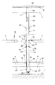
次に、添付図面に示した実施形態に基づき、本発明を更に詳細に説明する。図1〜図5は、本発明に係る間仕切パネルの構造を示し、図中符号1は天レール、2は地レール、3は支柱、4はアジャスター、5は天固定金具、6はパネル受け部材、7は横桟、8はパネル板、9は支持金具をそれぞれ示している。   Next, the present invention will be described in more detail based on the embodiments shown in the accompanying drawings. 1 to 5 show the structure of a partition panel according to the present invention, in which 1 is a ceiling rail, 2 is a ground rail, 3 is a column, 4 is an adjuster, 5 is a top fixing bracket, and 6 is a panel receiving member. , 7 are horizontal rails, 8 is a panel plate, and 9 is a support bracket.

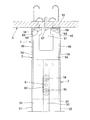
本発明に係る間仕切パネルは、天井Sに取付けた天レール1と床面Fに敷設した地レール2との間に所定間隔で支柱3,…を立設し、具体的には前記支柱3は下端に設けたアジャスター4を上向き開放の断面略コ字形の前記地レール2内に載支するとともに、該支柱3の上端に設けた天固定金具5を下方開放した断面略コ字形の前記天レール1の内部で天井Sにネジ止め固定し、隣接する支柱3,3間には下部に前記アジャスター4を利用してパネル受け部材6を架設するとともに、上下中間位置に単数又は複数の横桟7を横設して、隣接する支柱3,3の間隔を一定に保持し、そして両支柱3,3に適宜な係止手段にて表裏両面にパネル板8,8を係止して装着する。ここで、前記横桟7は、前記支柱3に取付けられた支持金具9によって連結されている。   In the partition panel according to the present invention, pillars 3,... Are erected at a predetermined interval between a ceiling rail 1 attached to a ceiling S and a ground rail 2 laid on a floor surface F. The adjuster 4 provided at the lower end is mounted on the ground rail 2 having a generally U-shaped cross section that is open upward, and the top fixing bracket 5 provided at the upper end of the support column 3 is opened downward. 1 is fixed to the ceiling S with a screw, and a panel receiving member 6 is installed between the adjacent columns 3 and 3 using the adjuster 4 at the lower part. The panel plates 8 and 8 are locked and attached to both the front and back surfaces of the columns 3 and 3 by appropriate locking means. Here, the horizontal rail 7 is connected by a support fitting 9 attached to the column 3.

本発明のパネル板8は、図3〜図5に示すように、スチール製の表面板10の周囲を裏面側へ折曲して縁部11を形成し、裏面側に石膏ボード等の防音性に優れた芯材12が接着された構造である。更に詳しくは、前記縁部11は、両側にあっては前記表面板10を裏面側に略直角に折曲して端面板13を形成し、更に該端面板13の後端を内方へ直角よりもやや小さな角度に折曲して裏面板14を形成し、該裏面板14には上下方向に所定間隔毎に縦長の係止孔15,…を形成し、上縁部にあっては前記表面板10の上端から裏面側へ略直角に折曲して上面板16を形成するとともに、該上面板16の端縁を下方へ略直角に折曲して補強板17を形成し、該補強板17の下端と前記芯材12の上面12Aとの間に空間Gを設けた構造である。尚、前記パネル板8の下縁部の構造も上縁部と同様であり、前記表面板10の下端から裏面側へ略直角に折曲して下面板18を形成するとともに、該下面板18の端縁を上方へ略直角に折曲して補強板19を形成し、縁部11を形成している。   As shown in FIGS. 3 to 5, the panel plate 8 of the present invention bends the periphery of the steel surface plate 10 to the back surface side to form the edge 11, and the soundproofing property such as gypsum board on the back surface side. This is a structure in which a core material 12 excellent in bonding is adhered. More specifically, the edge portion 11 is formed on both sides by bending the front surface plate 10 to the rear surface side at a substantially right angle to form an end surface plate 13, and the rear end of the end surface plate 13 is perpendicular to the inside. The back plate 14 is formed by bending at a slightly smaller angle, and the back plate 14 is formed with vertically long locking holes 15 at predetermined intervals in the vertical direction. The upper surface plate 16 is bent at a substantially right angle from the upper end of the front surface plate 10 to form the upper surface plate 16, and the reinforcing plate 17 is formed by bending the edge of the upper surface plate 16 downward at a substantially right angle. In this structure, a space G is provided between the lower end of the plate 17 and the upper surface 12A of the core member 12. The structure of the lower edge portion of the panel plate 8 is the same as that of the upper edge portion. The lower surface plate 18 is formed by bending the lower surface plate 10 from the lower end to the rear surface side at a substantially right angle. The reinforcing plate 19 is formed by bending the end edge of the upper edge substantially upward at a right angle, and the edge portion 11 is formed.

前記パネル板8を前記支柱3に係止するには、図1及び図2に示すように、前記支柱3の両側面で所定高さ位置に、前後両端部が該支柱3から突出するように係止板20をネジ止めする。この係止板20の両端部には、上向きフック部21,21が形成されており、該上向きフック部21に前記パネル板8の両側の裏面板14に形成した係止孔15を係止する。尚、前記パネル板8を前記支柱3に係止する構造は、前述のものに限らず、従来公知の各種係止手段を採用できる。   In order to lock the panel plate 8 to the support column 3, as shown in FIGS. 1 and 2, the front and rear ends protrude from the support column 3 at predetermined height positions on both side surfaces of the support column 3. The locking plate 20 is screwed. Upward hook portions 21 and 21 are formed at both ends of the locking plate 20, and the locking holes 15 formed in the back plate 14 on both sides of the panel plate 8 are locked to the upward hook portion 21. . In addition, the structure which latches the said panel board 8 to the said support | pillar 3 is not restricted to the above-mentioned thing, Various conventionally well-known latching means can be employ | adopted.

ここで、前記パネル板8の上部には予めシール材22が装着されており、前記パネル板8を支柱3に係止すると同時に、パネル板8の上部と天レール1との間の隙間が閉塞されるようになっている。前記シール材22は、図3に示すように、硬質と軟質の二種類のエラストマー等の弾性材料の押し出し成形品であり、前記パネル板8の補強板17と上面板16にかけて弾性的に外覆するとともに、補強板17の下端に係止する係止部23を備え、更に下方へ延びて前記芯材12に接触する第1シール部24と外側に突出して前記天レール1に接触する第2シール部25とを備えている。本実施形態では、前記シール材9の材質は、非鉛PVCとしている。   Here, a sealing material 22 is mounted on the upper portion of the panel plate 8 in advance, and the gap between the upper portion of the panel plate 8 and the top rail 1 is closed at the same time as the panel plate 8 is locked to the support column 3. It has come to be. As shown in FIG. 3, the sealing material 22 is an extruded product of an elastic material such as two types of hard and soft elastomers, and elastically covers the reinforcing plate 17 and the upper surface plate 16 of the panel plate 8. In addition, a locking portion 23 that locks to the lower end of the reinforcing plate 17 is provided. The first seal portion 24 that extends further downward and contacts the core member 12 and the second protruding to the outside and contacting the top rail 1 are provided. And a seal portion 25. In this embodiment, the material of the sealing material 9 is non-lead PVC.

前記パネル板8の下端は、図4に示すように、補強板19の一部を切起して下向きの突片26を形成し、前記パネル受け部材6の水平な受板27に形成した係合孔28に落とし込み係合して該パネル板8の面外方向の撓み変形を防止している。また、壁面Wに対しては、図5に示すように、前記支柱3は使用せず、該壁面Wに沿って側方開放した断面略コ字形の端部部材29を固定し、該端部部材29の凹溝内に配置した合成樹脂製のスペーサー部材30とで、前記パネル板8の側端部を弾性的に保持している。   As shown in FIG. 4, the lower end of the panel plate 8 cuts a part of the reinforcing plate 19 to form a downward protruding piece 26 and is formed on a horizontal receiving plate 27 of the panel receiving member 6. The panel board 8 is prevented from being bent and deformed by dropping and engaging with the joint hole 28. Further, as shown in FIG. 5, the column 3 is not used for the wall surface W, and an end member 29 having a substantially U-shaped cross section that is opened laterally along the wall surface W is fixed. The side end portion of the panel plate 8 is elastically held by the synthetic resin spacer member 30 disposed in the concave groove of the member 29.

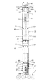
次に、各部の詳細を更に詳しく説明する。先ず、前記支柱3は、図1、図2及び図5に示すように、正面視において横幅が従来の支柱よりも狭く、奥行は従来の支柱と同じ寸法に設定され、軽量化とコストダウンが図られている。前記支柱3は、断面略C字形で外形形状が長方形の杆体であり、短辺側が正面を向くように配置する。前記支柱3は、スチール板を折曲して形成し、短辺側の前面板31と後面板32、長辺側の側面板33とその対面側の両側片34,34とで形成され、両側片34,34間には隙間があるが、勿論隙間が無くても良い。本実施形態の支柱3の横幅は狭いので、前記前面板31と後面板32に、前記パネル板8を係止するための係止孔を2列形成し、係止具によってパネル板8を係止することが難しい。そのため、前記係止板20を前記支柱3の側面板33及び両側片34,34にネジ止めしたのである。   Next, details of each part will be described in more detail. First, as shown in FIG. 1, FIG. 2 and FIG. 5, the support column 3 is narrower than the conventional support column in the front view, and the depth is set to the same dimensions as the conventional support column, thereby reducing weight and cost. It is illustrated. The support column 3 is a casing having a substantially C-shaped cross section and a rectangular outer shape, and is arranged so that the short side faces the front. The support column 3 is formed by bending a steel plate, and is formed by a front plate 31 and a rear plate 32 on the short side, a side plate 33 on the long side, and both side pieces 34 and 34 on the opposite side. Although there is a gap between the pieces 34, 34, of course, there may be no gap. Since the horizontal width of the column 3 of this embodiment is narrow, two rows of locking holes for locking the panel plate 8 are formed in the front plate 31 and the rear plate 32, and the panel plate 8 is engaged by a locking tool. It is difficult to stop. Therefore, the locking plate 20 is screwed to the side plate 33 and the side pieces 34, 34 of the support column 3.

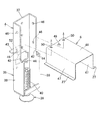
前記アジャスター4は、図1、図2、図6〜図9に示すように、正面視において下半分は従来と同様な横幅を有し、前記支柱3の下端部を嵌着する上半分は前記支柱3の横幅に応じて横幅を小さくした形状であり、前記支柱3の下端部に装着するアジャスター受け部材35と、該アジャスター受け部材35に鉛直方向から螺合して前記地レール2内に載置するアジャスターボルト36とからなるとともに、両側にパネル板8の下端を支えるパネル受け部材6を支持するための係止手段を備えている。具体的には、前記アジャスター受け部材35は、一側面となる連結板37の両側から直角に前板38と後板39を折曲して平面視略コ字形とし、更に前記連結板37の下端を直角に折曲して水平な底面板40を形成して前記前板38と後板39の間の空間を塞ぐとともに、該底面板40の両縁部を前記前板38と後板39の下端に当接し、荷重を受けても変形しないようにしている。前記底面板40の中央部には螺孔41を形成し、前記アジャスターボルト36を下方から螺合している。   As shown in FIGS. 1, 2, and 6 to 9, the adjuster 4 has a horizontal width similar to that of the prior art in the front view, and the upper half that fits the lower end portion of the column 3 is The width of the column 3 is reduced according to the width of the column 3. The adjuster receiving member 35 attached to the lower end of the column 3 is screwed into the adjuster receiving member 35 from the vertical direction and mounted in the ground rail 2. In addition to an adjuster bolt 36 to be placed, locking means for supporting the panel receiving member 6 that supports the lower end of the panel plate 8 is provided on both sides. Specifically, the adjuster receiving member 35 has a substantially U-shape in plan view by bending the front plate 38 and the rear plate 39 at right angles from both sides of the connecting plate 37 which is one side surface. Are bent at right angles to form a horizontal bottom plate 40 to close the space between the front plate 38 and the rear plate 39, and both edges of the bottom plate 40 are connected to the front plate 38 and the rear plate 39. It is in contact with the lower end so that it will not be deformed even if it receives a load. A screw hole 41 is formed in the central portion of the bottom plate 40, and the adjuster bolt 36 is screwed from below.

前記アジャスター受け部材35の前板38と後板39は、図6及び図7に示すように、上下中間位置で段差部42を設けて上半分の横幅を狭く、下半分の横幅を広く形成し、前記連結板37の上下中間位置に前記段差部42と上面が同一高さレベルに係止片43を切起し形成するとともに、前記段差部42の外側端部には、前記前板38と後板39の面より内側に側面視L字状に上向きの係止爪44,44を形成している。   As shown in FIGS. 6 and 7, the front plate 38 and the rear plate 39 of the adjuster receiving member 35 are provided with a stepped portion 42 at the upper and lower intermediate positions so that the width of the upper half is narrow and the width of the lower half is wide. The step plate 42 and the upper surface of the connecting plate 37 are formed at the same height level by cutting and forming a locking piece 43 at an intermediate position between the front plate 38 and the outer end portion of the step plate 42. Locking claws 44 and 44 are formed on the inner side of the rear plate 39 so as to be L-shaped in a side view.

つまり、前記アジャスター受け部材35は、正面視において上下中間位置に段差部42を設けて上半分の横幅を狭く、下半分の横幅を広く形成し、上半分に前記支柱3の下端部を嵌着し、前記段差部42と反対側の面に前記パネル受け部材6の端部を載支してネジ止めする係止片43を切起し形成するとともに、前記段差部42に前記パネル受け部材6の端部に形成した孔に係合する上向きの係止爪44,44を形成したことが特徴であり、その他の構成は適宜変更可能である。   In other words, the adjuster receiving member 35 is provided with a stepped portion 42 at the upper and lower intermediate positions in a front view so that the upper half has a narrow width and the lower half has a wide width, and the lower end of the column 3 is fitted to the upper half. Then, an engaging piece 43 is formed by cutting and forming the end of the panel receiving member 6 on the surface opposite to the stepped portion 42 and screwing it, and the panel receiving member 6 is formed on the stepped portion 42. It is the feature that the upward latching claws 44 and 44 which engage with the hole formed in the edge part of this are formed, and other structures can be changed suitably.

前記支柱3の下端部は、図8及び図9に示すように、前面板31と後面板32を残して、前記側面板33と両側片34,34を切り欠いた形状であり、この切欠端45は該支柱3の下端部を前記アジャスター受け部材35の上半分に外嵌した際に、前記段差部42と係止片43の上面に当止される。また、前記アジャスター受け部材35の前板38と後板39の外面であって、前記支柱3に嵌合する部分には外向きに突出した片球状突起46,46を上下に形成し、支柱3に密嵌するようになっている。   As shown in FIGS. 8 and 9, the lower end portion of the column 3 has a shape in which the side plate 33 and both side pieces 34, 34 are cut out, leaving the front plate 31 and the rear plate 32. 45 is abutted against the upper surface of the stepped portion 42 and the locking piece 43 when the lower end portion of the support column 3 is externally fitted to the upper half of the adjuster receiving member 35. In addition, on the outer surfaces of the front plate 38 and the rear plate 39 of the adjuster receiving member 35, one-side projections 46, 46 projecting outward are formed vertically on the portion fitted to the column 3. It is designed to fit tightly.

そして、前記支柱3の下端部に装着された前記アジャスター4によって、前記パネル受け部材6の端部が支持される。具体的には、図6に示すように、前記パネル受け部材6は、前記地レール2の上部を外被することができる下方開放の断面略コ字形の長尺部材であり、前記地レール2の外側に位置する垂直な吊板47の下縁には外向きに前記受板27を折曲形成し、また上板48の端部には、中央部に取付孔49、その左右部に前記保持孔50,50が形成されている。ここで、前記保持孔50の形状は角孔としたが、円孔でも構わない。そして、前記アジャスター受け部材35の係止片43が形成されている側では、前記パネル受け部材6の端部を該係止片43に載置し、前記取付孔49に挿通したタッピンネジ51を係止片43に形成した下穴52に螺合し、その反対側にあっては前記パネル受け部材6の端部を両段差部42,42に載置すると同時に、両係止爪44,44を両保持孔50,50に受け入れて係合する。   The end of the panel receiving member 6 is supported by the adjuster 4 attached to the lower end of the column 3. Specifically, as shown in FIG. 6, the panel receiving member 6 is a long member having a substantially U-shaped cross section that is open downward and can cover the upper part of the ground rail 2. The receiving plate 27 is bent outwardly at the lower edge of the vertical suspension plate 47 located outside the mounting plate 49 at the center of the end of the upper plate 48 and the left and right sides of the mounting hole 49. Holding holes 50 are formed. Here, although the shape of the holding hole 50 is a square hole, it may be a circular hole. Then, on the side of the adjuster receiving member 35 where the locking piece 43 is formed, the end of the panel receiving member 6 is placed on the locking piece 43 and the tapping screw 51 inserted through the mounting hole 49 is engaged. The end of the panel receiving member 6 is placed on both stepped portions 42 and 42 at the same time, and at the same time, both locking claws 44 and 44 are screwed into a pilot hole 52 formed in the stopper 43. It is received and engaged with both holding holes 50, 50.

また、前記アジャスター受け部材35の連結板37の上半分において、中央線に沿って少なくとも上下2箇所に通孔53,…を形成してあり、天井Sまで達しない中間高さの間仕切パネルでは、前記支柱3を天井Sに固定することができないので、前記支柱3とアジャスター受け部材35を、前記通孔53,…を利用してネジ止め、あるいは圧接して強固に連結する。   Further, in the upper half of the connecting plate 37 of the adjuster receiving member 35, through holes 53 are formed at least at two locations above and below the center line, and the intermediate height partition panel does not reach the ceiling S. Since the column 3 cannot be fixed to the ceiling S, the column 3 and the adjuster receiving member 35 are firmly connected to each other by screwing or press-contacting using the through holes 53.

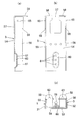
前天固定金具5は、図1、図2、図10〜図14に示すように、前記アジャスター受け部材35と同様に、一側面となる連結板54の両側から直角に前板55と後板56を折曲して平面視略コ字形とし、更に前記連結板54の上端部の中央に切欠部57を形成するとともに、該切欠部57の両側の連結板54の上端に固定片58,58を折曲形成している。前記天固定金具5の下部は、前記支柱3の上端部に上下スライド可能に嵌挿する大きさに設定し、該支柱3に対する固定には、締付ネジ59による圧接を利用する。つまり、前記連結板54の下部の幅方向中央部に、前板55と後板56で形成される凹溝内に向けて一部を膨出させて固定台部60を形成し、該固定台部60の上下に形成した複数の下穴61,…に凹溝内からタッピンネジからなる前記締付ネジ59を螺合する。そして、図12及び図13に示すように、前記天固定金具5の下部を、凹溝側を前記側片34,34側に向けて前記支柱3に嵌挿した状態で、前記側片34,34の間に臨む前記締付ネジ59の頭部をドライバーで回して、該締付ネジ59の先端を前記支柱3の側面板33の内面に圧接することにより、前板55と後板56の側縁が前記支柱3の両側片34,34の内面に圧接して、その摩擦力によって固定させるのである。   As shown in FIGS. 1, 2, and 10 to 14, the front ceiling fixture 5 is similar to the adjuster receiving member 35 in that the front plate 55 and the rear plate 56 are perpendicular to both sides of the connecting plate 54 that is one side surface. And a notch 57 is formed at the center of the upper end of the connecting plate 54, and fixing pieces 58 and 58 are provided at the upper ends of the connecting plates 54 on both sides of the notch 57. Bending is formed. The lower part of the ceiling fixing bracket 5 is set to a size that can be inserted into the upper end of the support column 3 so as to be vertically slidable. That is, a fixed base portion 60 is formed by bulging a part in a concave groove formed by the front plate 55 and the rear plate 56 at a central portion in the width direction of the lower portion of the connecting plate 54, The fastening screw 59 made of a tapping screw is screwed into the plurality of prepared holes 61 formed on the top and bottom of the portion 60 from the inside of the groove. Then, as shown in FIGS. 12 and 13, the side piece 34, with the lower part of the top fixing bracket 5 fitted in the support column 3 with the groove side facing the side piece 34, 34 side, 34, by turning the head of the fastening screw 59 facing between 34 with a screwdriver and pressing the tip of the fastening screw 59 against the inner surface of the side plate 33 of the column 3, the front plate 55 and the rear plate 56 The side edges are pressed against the inner surfaces of the two side pieces 34, 34 of the column 3 and fixed by the frictional force.

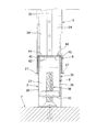
また、前記天固定金具5の固定片58,58は、前記前板55と後板56の側縁よりも側方へ延び、その先端部には前記天レール1あるいは天井Sにネジ止めするための通孔63を形成している。そして、前記固定片58,58は、前記天レール1の天面板62の下面に当接し、該固定片58に形成した通孔63に下方から挿入した固定ネジ64で前記天面板62とともに天井Sにネジ止めする。尚、前記天固定金具5の前板55と後板56の上部には外側へ小さな突出部65,65をプレス形成し、前記天レール1の両垂下板66,66の内面に密接するようにしている。また、前記天固定金具5の切欠部57は、前記天レール1を天井Sに固定するための固定ネジ67を逃がすためのものであり、該天固定金具5の天レール1のどの位置でも固定できるようにしている。また、前記天レール1内に沿って配線することもあるので、配線コードを挿通するために、前記切欠部57を大きく形成している。   The fixing pieces 58 of the top fixing bracket 5 extend laterally from the side edges of the front plate 55 and the rear plate 56, and are screwed to the top rail 1 or the ceiling S at the front ends thereof. The through-hole 63 is formed. The fixing pieces 58, 58 are in contact with the lower surface of the top plate 62 of the top rail 1, and the ceiling S together with the top plate 62 is fixed by a fixing screw 64 inserted from below into a through hole 63 formed in the fixing piece 58. Screw on to. Note that small protrusions 65 and 65 are press-formed on the top of the front plate 55 and the rear plate 56 of the top fixing bracket 5 so as to be in close contact with the inner surfaces of the two hanging plates 66 and 66 of the top rail 1. ing. Further, the notch 57 of the ceiling fixing bracket 5 is for releasing a fixing screw 67 for fixing the ceiling rail 1 to the ceiling S, and is fixed at any position on the ceiling rail 1 of the ceiling fixing bracket 5. I can do it. In addition, since wiring may be performed along the top rail 1, the cutout portion 57 is formed large in order to insert a wiring cord.

ここで、前記支柱3の上端は、立起状態において施工性を考慮して前記天レール1の垂下板66の下端よりも低い位置になるように設定している。そのため、前記天固定金具5の締付ネジ59を緩めた状態でも、該天固定金具5が前記天レール1の垂下板66の下端より下がらないようにするため、前記前板55と後板56の上部に幅広部68を設けて横幅を広くしている。前記幅広部68は図示したように段差を設けた横幅が広がっても、また徐々に傾斜して広がっても良い。つまり、図14に示すように、前記支柱3の上端部に嵌挿した前記天固定金具5が下がって、前記幅広部68が前記支柱3の側片34,34の上端に当止した状態になっても、該天固定金具5の上部が前記天レール1の両垂下板66,66の下端よりも高い位置に保持され、もって前記天固定金具5によって天井Sに固定する前に、前記支柱3が不意に前後方向に倒れないようにしている。それに対して、従来は、立起状態の支柱3の上端部が常に天レール1に重なって係合しているような構造であったため、該支柱3が前後方向に倒れる恐れはなかったが、支柱3が長くなって施工性が悪いという問題を有していた。   Here, the upper end of the column 3 is set to be lower than the lower end of the hanging plate 66 of the ceiling rail 1 in consideration of workability in the standing state. Therefore, the front plate 55 and the rear plate 56 are arranged so that the top fixing bracket 5 does not fall below the lower end of the hanging plate 66 of the top rail 1 even when the fastening screw 59 of the top fixing bracket 5 is loosened. A wide portion 68 is provided on the upper portion of the frame to increase the lateral width. As shown in the drawing, the wide portion 68 may be widened with a step or may be gradually inclined and widened. That is, as shown in FIG. 14, the ceiling fixing metal fitting 5 fitted and inserted into the upper end portion of the column 3 is lowered, and the wide portion 68 is in contact with the upper ends of the side pieces 34 and 34 of the column 3. In this case, the upper part of the ceiling fixing bracket 5 is held at a position higher than the lower ends of the two hanging plates 66, 66 of the ceiling rail 1, so that the column is fixed before being fixed to the ceiling S by the ceiling fixing bracket 5. 3 prevents accidental falls in the front-rear direction. On the other hand, because the structure is such that the upper end of the upright column 3 is always overlapped and engaged with the top rail 1, there is no fear that the column 3 will fall down in the front-rear direction. There was a problem that the column 3 was long and the workability was poor.

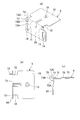
次に、前記横桟7を、支持金具9を用いて前記支柱3,3間に架設する構造を、図1、図2、図15〜図18に基づいて説明する。前記横桟7は、下向き開放した断面略コ字形の長尺部材であり、前記パネル受け部材6と同じ長さに設定し、隣接する前記支柱3,3の間隔を正確に一定に設定しながら、該支柱3を立起状態に施工できるようにしている。前記支持金具9は、厚さ1mm以下、好ましくは厚さ0.8mmのスチール板から作成し、垂直な固定板69と水平な支持板70とを有する正面視略L字形に形成した部材であり、該固定板69と支持板70の屈曲部71の近傍に幅の狭いくびれ部72を形成するとともに、該くびれ部72に対応する前記固定板69の両側に上向きフック片73,73を切起して形成している。   Next, a structure in which the horizontal rail 7 is installed between the support columns 3 and 3 using the support fitting 9 will be described with reference to FIGS. 1, 2, and 15 to 18. The crosspiece 7 is a long member having a substantially U-shaped cross section opened downward, and is set to the same length as the panel receiving member 6 while setting the interval between the adjacent support columns 3 and 3 to be exactly constant. The strut 3 can be constructed in an upright state. The support fitting 9 is a member made of a steel plate having a thickness of 1 mm or less, preferably 0.8 mm, and having a vertical fixing plate 69 and a horizontal support plate 70 and formed in a substantially L shape in front view. A narrow neck portion 72 is formed in the vicinity of the bent portion 71 of the fixing plate 69 and the support plate 70, and upward hook pieces 73, 73 are cut up on both sides of the fixing plate 69 corresponding to the neck portion 72. And formed.

前記フック片73は、前記固定板69に直角で前記支持板70とは反対側に延びた基部73Aと、該基部73Aから前記屈曲部71の側へ直角に延びた先端部73Bを有する正面視略L字形であり、該先端部73Bの先端で前記屈曲部71の側に小さく突出した当止部73Cを形成している。また、前記固定板69の両側部には縦長の長孔74,74を形成するとともに、前記支持板70の中央に下方へバーリング加工した連結孔75を形成している。尚、前記連結孔75は、タッピンネジを用いる場合には下穴となり、通常の小ネジを用いる場合には螺孔とする。また、前記支持金具9は、板厚が薄いため、前記固定板69を平らな面に取付ける際に、前記フック片73が邪魔になった場合にはプライヤー等で簡単に曲げて該固定板69の面と面一にすることができる。   The hook piece 73 has a base portion 73A extending at a right angle to the fixing plate 69 and opposite to the support plate 70, and a front end portion 73B extending from the base portion 73A toward the bent portion 71 at a right angle. The stopper portion 73C is substantially L-shaped and protrudes small toward the bent portion 71 at the tip of the tip portion 73B. Further, vertically long holes 74 and 74 are formed on both sides of the fixed plate 69, and a connecting hole 75 burring downward is formed in the center of the support plate 70. The connection hole 75 is a pilot hole when a tapping screw is used, and is a screw hole when a normal machine screw is used. Further, since the support metal fitting 9 is thin, when the fixing plate 69 is attached to a flat surface, if the hook piece 73 gets in the way, it can be easily bent by a pliers or the like. It can be flush with the surface.

図15及び図18に示すように、前記支持金具9を取付ける前記支柱3の側面板33と両側片34,34には、その面の両側部に一対の係合孔76,76を並設してある。つまり、前記側面板33には左右両側部に、前記側片34,34にはそれぞれに係合孔76を形成している。前記係合孔76は、縦長孔であても円形孔であっても構わないが、加工性から円形孔が好ましい。前記支持金具9を支柱3に取付けるには、図15に示すように、前記支持板70を上方に向けた傾斜状態で、前記フック片73,73を前記支柱3の係合孔76,76に挿入し、前記屈曲部71を支柱3の側面に当接して該屈曲部71を支点として前記固定板69が垂直に、前記支持板70が水平になるまで回転させると、前記固定板69が支柱3の側面に当接し、前記フック片73が深く係合して当止部73Cが側面板33あるいは側片34の内面に当接した状態で保持される。それから、前記横桟7の下向き凹溝内に前記支持金具9の支持板70を受け入れ、横桟7の水平な上板77を支持板70に載置し、該上板77の通孔に挿通したネジ78を前記連結孔75に螺合して連結する。尚、前記支持金具9の支持板70に横桟7を連結してそのままの姿勢を維持できる場合には、前記フック片73が支柱3の係合孔76から抜けることがないので、前記固定板69を支柱3に必ずしもネジ止めする必要はないが、前記支柱3,3間の連結強度を高めるために、前記固定板69を長孔74,74を利用して支柱3の側面板33あるいは側片34,34にネジ止めすることも好ましい。   As shown in FIGS. 15 and 18, the side plate 33 and the side pieces 34, 34 of the column 3 to which the support fitting 9 is attached are provided with a pair of engagement holes 76, 76 on both sides of the surface. It is. That is, the side plate 33 is formed with engaging holes 76 on both the left and right sides, and the side pieces 34 and 34 are respectively formed. The engagement hole 76 may be a vertically long hole or a circular hole, but a circular hole is preferable in terms of workability. In order to attach the support fitting 9 to the support column 3, as shown in FIG. 15, the hook pieces 73 and 73 are inserted into the engagement holes 76 and 76 of the support column 3 with the support plate 70 tilted upward. When the bending portion 71 is inserted into contact with the side surface of the support column 3 and the fixing plate 69 is rotated with the bending portion 71 as a fulcrum until the support plate 70 becomes horizontal, the fixing plate 69 is supported by the support column 70. 3, the hook piece 73 is deeply engaged, and the stopper 73 </ b> C is held in contact with the inner surface of the side plate 33 or the side piece 34. Then, the support plate 70 of the support fitting 9 is received in the downward concave groove of the horizontal beam 7, the horizontal upper plate 77 of the horizontal beam 7 is placed on the support plate 70, and is inserted into the through hole of the upper plate 77. The screw 78 is screwed into the connecting hole 75 and connected. When the horizontal beam 7 can be connected to the support plate 70 of the support fitting 9 and the posture can be maintained as it is, the hook piece 73 does not come out of the engagement hole 76 of the support column 3, so that the fixing plate 69 is not necessarily screwed to the column 3, but in order to increase the connection strength between the columns 3, 3, the fixing plate 69 is connected to the side plate 33 or the side of the column 3 using the long holes 74, 74. It is also preferable to screw the pieces 34, 34.

1 天レール、 2 地レール、
3 支柱、 4 アジャスター、
5 天固定金具、 6 パネル受け部材、
7 横桟、 8 パネル板、
9 支持金具、 10 表面板、
11 縁部、 12 芯材、
13 端面板、 14 裏面板、
15 係止孔、 16 上面板、
17 補強板、 18 下面板、
19 補強板、 20 係止板、
21 上向きフック部、 22 シール材、
23 係止部、 24 第1シール部、
25 第2シール部、 26 突片、
27 受板、 28 係合孔、
29 端部部材、 30 スペーサー部材、
31 前面板、 32 後面板、
33 側面板、 34 側片、
35 アジャスター受け部材、36 アジャスターボルト、
37 連結板、 38 前板、
39 後板、 40 底面板、
41 螺孔、 42 段差部、
43 係止片、 44 係止爪、
45 切欠端、 46 突起、
47 吊板、 48 上板、
49 取付孔、 50 保持孔、
51 タッピンネジ、 52 下穴、
53 通孔、 54 連結板、
55 前板、 56 後板、
57 切欠部、 58 固定片、
59 締付ネジ、 60 固定台部、
61 下穴、 62 天面板、
63 通孔、 64 固定ネジ、
65 突出部、 66 垂下板、
67 固定ネジ、 68 幅広部、
69 固定板、 70 支持板、
71 屈曲部、 72 くびれ部、
73 フック片、 73A 基部、
73B 先端部、 73C 当止部、
74 長孔、 75 連結孔、
76 係合孔、 77 上板、
78 ネジ、
F 床面、
S 天井、
W 壁面。
1 top rail, 2 ground rail,
3 struts, 4 adjusters,
5 Top fixing bracket, 6 Panel support member,
7 horizontal rails, 8 panel boards,
9 Support bracket, 10 Surface plate,
11 edge, 12 core material,
13 end plate, 14 back plate,
15 locking holes, 16 top plate,
17 reinforcement plate, 18 bottom plate,
19 reinforcing plate, 20 locking plate,
21 upward hook part, 22 sealing material,
23 locking portion, 24 first seal portion,
25 second seal part, 26 projecting piece,
27 receiving plate, 28 engaging hole,
29 end member, 30 spacer member,
31 front plate, 32 rear plate,
33 side plates, 34 side pieces,
35 adjuster receiving member, 36 adjuster bolt,
37 connecting plate, 38 front plate,
39 back plate, 40 bottom plate,
41 screw holes, 42 steps,
43 locking pieces, 44 locking claws,
45 notched ends, 46 protrusions,
47 Suspension plate, 48 Upper plate,
49 mounting holes, 50 holding holes,
51 tapping screws, 52 pilot holes,
53 through holes, 54 connecting plates,
55 Front plate, 56 Rear plate,
57 cutouts, 58 fixed pieces,
59 Tightening screws, 60 fixing base,
61 pilot hole, 62 top plate,
63 through holes, 64 fixing screws,
65 protrusions, 66 hanging plates,
67 fixing screws, 68 wide part,
69 fixed plate, 70 support plate,
71 bent portion, 72 constricted portion,
73 hook piece, 73A base,
73B tip, 73C stop,
74 long holes, 75 connecting holes,
76 engagement holes, 77 upper plate,
78 screws,
F floor,
S ceiling,
W Wall surface.

Claims (3)

天レールと地レール間にパネル板を支持する支柱を立設し、該支柱の上端部に装着した天固定金具で天レールあるいは天井に固定する構造の間仕切パネルにおいて、前記天レールは下方開放した断面略コ字形であり、前記支柱の上端部に上下スライド可能に嵌挿した天固定金具を側方からネジによる突っ張りによって上下動不能に固定し、該天固定金具の上端に設けた固定片を天レールの天面板に接合してネジ止め固定可能な構造の支柱固定装置であって、前記天固定金具は、一側面となる連結板の両側から直角に前板と後板を折曲して平面視略コ字形とし、前記連結板の上端部の中央に切欠部を形成するとともに、該切欠部の両側に前記固定片を設け、更に前記前板と後板の上部に横幅を広くして前記支柱の上端に当止する幅広部を設けていることを特徴とする間仕切パネルにおける支柱固定装置。 In the partition panel that has a structure in which a column supporting the panel plate is erected between the ceiling rail and the ground rail and is fixed to the ceiling rail or the ceiling with the ceiling fixing bracket attached to the upper end of the column, the ceiling rail is opened downward. a approximately C-shaped cross section, the upper and lower slidably fitted interpolated upper fixing bracket vertical movement incapable fixed by bracing with screws from the side to the upper end of the strut, the fixing piece provided at the upper end of the top fixing bracket The column fixing device has a structure that can be fixed to the top plate of the top rail by screwing , and the top fixing bracket is formed by bending the front plate and the rear plate at right angles from both sides of the connecting plate on one side. It has a substantially U shape in plan view, and a notch is formed at the center of the upper end of the connecting plate, the fixing pieces are provided on both sides of the notch, and the lateral width is widened above the front and rear plates. provided wide portion for abutting-stops to the upper end of said post Post fixing device in partition panel, characterized in that that. 前記支柱の上端は、立起状態において前記天レールの下端よりも低い位置になるように設定し、前記天固定金具の幅広部が前記支柱の上端に当接した状態でも、該天固定金具上部が前記天レールの下端よりも高い位置に保持されている請求項記載の間仕切パネルにおける支柱固定装置。 The upper end of the column is set to be lower than the lower end of the ceiling rail in the upright state, and the upper part of the ceiling fixing bracket is fixed even when the wide part of the ceiling fixing bracket is in contact with the upper end of the column. There strut fixing device in partition panel according to claim 1, wherein held in a position higher than the lower end of the top rail. 前記天固定金具の固定片は、前記前板と後板の側縁よりも側方へ延び、その先端部には前記天レールあるいは天井にネジ止めするための通孔を形成してなる請求項記載の間仕切パネルにおける支柱固定装置。 The fixing piece of the top fixing bracket extends to the side from the side edge of the front plate and the rear plate, and a through hole for screwing to the top rail or the ceiling is formed at a tip portion thereof. The support | pillar fixing device in the partition panel of 1 description.
JP2015110957A 2015-05-29 2015-05-29 Column fixing device for partition panel Active JP6558080B2 (en)

Priority Applications (1)

Application Number Priority Date Filing Date Title
JP2015110957A JP6558080B2 (en) 2015-05-29 2015-05-29 Column fixing device for partition panel

Applications Claiming Priority (1)

Application Number Priority Date Filing Date Title
JP2015110957A JP6558080B2 (en) 2015-05-29 2015-05-29 Column fixing device for partition panel

Publications (2)

Publication Number Publication Date
JP2016223174A JP2016223174A (en) 2016-12-28
JP6558080B2 true JP6558080B2 (en) 2019-08-14

Family

ID=57747498

Family Applications (1)

Application Number Title Priority Date Filing Date
JP2015110957A Active JP6558080B2 (en) 2015-05-29 2015-05-29 Column fixing device for partition panel

Country Status (1)

Country Link
JP (1) JP6558080B2 (en)

Families Citing this family (3)

* Cited by examiner, † Cited by third party
Publication number Priority date Publication date Assignee Title
JP7033290B2 (en) * 2017-06-29 2022-03-10 吉野石膏株式会社 Partition wall and its construction method
CN107100294B (en) * 2017-07-03 2023-04-11 中建一局集团装饰工程有限公司 System partition system and construction method thereof
BR112020010918A2 (en) 2017-11-29 2020-11-17 Armstrong World Industries, Inc. end cap for roof panel and roof system that incorporates the same

Family Cites Families (3)

* Cited by examiner, † Cited by third party
Publication number Priority date Publication date Assignee Title
JPS586971Y2 (en) * 1977-12-24 1983-02-07 株式会社伊藤喜工作所 Structure of partition post attachment part
JPH0328209U (en) * 1989-07-26 1991-03-20
US6158179A (en) * 1998-03-10 2000-12-12 Steelcase Development Inc. Overhead structures for wall system

Also Published As

Publication number Publication date
JP2016223174A (en) 2016-12-28

Similar Documents

Publication Publication Date Title
JP2008542645A (en) Sheet metal fasteners and clips
JP5702264B2 (en) Field edge mounting structure
JP6558080B2 (en) Column fixing device for partition panel
JP2007159865A (en) Shelf board and mounting structure thereof
JP6497219B2 (en) Adjuster device for partition panel
JP5772664B2 (en) Adjuster device in partition device
JP6511966B2 (en) Door frame mounting device for partition panel
JP5929650B2 (en) Earthquake-resistant partition panel
JP7329211B2 (en) External wall material holder
JP5266115B2 (en) Outer wall material mounting bracket and outer wall material mounting structure
JP2018031178A (en) Ceiling joist fitting device
JP2016223172A (en) Cross rail support device for partition panel
JP2013121270A (en) Wiring duct device of post
JP2008008112A (en) Partition wall
JP6503899B2 (en) Edge processing apparatus in partition panel
JP6565341B2 (en) Deflection prevention device for partition panel
JP7280701B2 (en) Exterior wall material fixtures and exterior wall material mounting structure
JP2020076252A (en) Metal fitting for construction
JP2016223171A (en) Deflection prevention device for partition panel
JP6511967B2 (en) Mounting device for adjuster support member on door frame
JP4108079B2 (en) Shelf support structure of assembly house
JP4133689B2 (en) Rocking exterior wall panels
JP6299161B2 (en) Panel plate locking device in earthquake-resistant partitioning device
JP2006305024A (en) Mounting structure of shelf bracket
KR20110027465A (en) The ceiling panel

Legal Events

Date Code Title Description
A621 Written request for application examination

Free format text: JAPANESE INTERMEDIATE CODE: A621

Effective date: 20180514

A977 Report on retrieval

Free format text: JAPANESE INTERMEDIATE CODE: A971007

Effective date: 20190206

A131 Notification of reasons for refusal

Free format text: JAPANESE INTERMEDIATE CODE: A131

Effective date: 20190212

A521 Written amendment

Free format text: JAPANESE INTERMEDIATE CODE: A523

Effective date: 20190411

TRDD Decision of grant or rejection written
A01 Written decision to grant a patent or to grant a registration (utility model)

Free format text: JAPANESE INTERMEDIATE CODE: A01

Effective date: 20190618

A61 First payment of annual fees (during grant procedure)

Free format text: JAPANESE INTERMEDIATE CODE: A61

Effective date: 20190701

R150 Certificate of patent or registration of utility model

Ref document number: 6558080

Country of ref document: JP

Free format text: JAPANESE INTERMEDIATE CODE: R150