JP5772664B2 - Adjuster device in partition device - Google Patents
Adjuster device in partition device Download PDFInfo
- Publication number
- JP5772664B2 JP5772664B2 JP2012046951A JP2012046951A JP5772664B2 JP 5772664 B2 JP5772664 B2 JP 5772664B2 JP 2012046951 A JP2012046951 A JP 2012046951A JP 2012046951 A JP2012046951 A JP 2012046951A JP 5772664 B2 JP5772664 B2 JP 5772664B2
- Authority
- JP
- Japan
- Prior art keywords
- adjuster
- receiving member
- locking
- plate
- locking piece
- Prior art date
- Legal status (The legal status is an assumption and is not a legal conclusion. Google has not performed a legal analysis and makes no representation as to the accuracy of the status listed.)
- Active
Links
Images


Description
本発明は、間仕切装置におけるアジャスター装置に関するものである。 The present invention relates to an adjuster device in a partition device.
従来から、天レールと地レールの間に下端にアジャスターを嵌着した支柱を、間隔を隔てて複数立設するとともに、該支柱の表裏両面にパネル板を取付けてフロアを区画してなる間仕切装置は各種提供されている(特許文献1参照)。 Conventionally, a partition device in which a plurality of support columns, each having an adjuster fitted between the top rail and the ground rail, are erected at intervals, and a panel is attached to both front and back surfaces of the support column to partition the floor. Are provided in various ways (see Patent Document 1).
更に詳しくは、前記支柱は、スチール板を折曲形成した中空杆体であり、一側面に上下方向に開口した間隙を有するものである。前記アジャスターは、前記支柱の下端部に嵌入する受け部材と、該受け部材の下面に螺合したアジャスターボルトからなっている。前記受け部材は、スチール板を角パイプ状に折曲して形成した筒体であり、上端部は内方へ先細となるように折曲して支柱への嵌入を案内する傾斜部を形成し、側面の上下中間部に全て上端を同一高さとした複数のダボを突設するとともに、該受け部材の両側面に一対の係止片を切起し形成したものである。また、アジャスターを地レールに設置したまま高さ調節できるように、前記アジャスターボルトの上端にはドライバーを差し込むための係合溝を形成している。 More specifically, the support column is a hollow casing formed by bending a steel plate, and has a gap opened in the vertical direction on one side surface. The adjuster includes a receiving member that is fitted into the lower end portion of the support column, and an adjuster bolt that is screwed into the lower surface of the receiving member. The receiving member is a cylindrical body formed by bending a steel plate into a square pipe shape, and an upper end portion is bent so as to be tapered inward to form an inclined portion that guides insertion into a support column. In addition, a plurality of dowels having the same upper end at the upper and lower intermediate portions of the side surfaces are projected, and a pair of locking pieces are cut and formed on both side surfaces of the receiving member. In addition, an engagement groove for inserting a screwdriver is formed at the upper end of the adjuster bolt so that the height can be adjusted while the adjuster is installed on the ground rail.
ここで、前記アジャスターの受け部材に突設した係止片が、間仕切装置の表裏両面に位置する向きにアジャスターを設定し、前記支柱の下端を当止するとともに、パネル板の下端部を係止する機能を持たせている。しかし、間仕切装置のパネル面に面する表裏両面に係止片を突設したので、パネル板の端面板には側方へ突出した固定縁を設けるとともに、該固定縁に前記係止片に係止するための切欠段部を形成する必要があり、特殊なパネル板の構造となる。 Here, the locking pieces projecting from the receiving member of the adjuster set the adjusters so that they are positioned on both the front and back surfaces of the partition device, and the lower end of the column is abutted and the lower end of the panel plate is locked. It has a function to do. However, since the locking pieces project on both the front and back surfaces facing the panel surface of the partitioning device, the end plate of the panel plate is provided with a fixed edge protruding sideways, and the fixed edge is engaged with the locking piece. It is necessary to form a notch step for stopping, and a special panel board structure is obtained.
また、特許文献2には、アジャスターボルトを螺合したベース体を地レール内に配置し、該ベース体に外嵌し且つアジャスターボルトで支持される脚体の左右両側に支持金具を着脱自在に取付け、該脚体には支柱の下端部を外挿して立起状態に支持するとともに、間隔を隔てた両脚体の対向する一対の支持金具にパネル支持体の両端部を連結し、隣接する両支柱の表裏両面に係止具を用いてパネル板の両側縁を係止するとともに、パネル板の下端を前記パネル支持体に載支する構造の間仕切装置における支持装置が開示されている。
Further, in
しかし、特許文献2に記載のものは、必要な箇所にのみ支持金具を取付けることができるという利点はあるものの、部品点数が多くコスト高であるとともに、ベース体に脚体を載支した状態では、アジャスターボルトを回して高さを調節することができず、作業性に問題があった。特に、パネル建て込み施工後に、支柱高さの微調整をする場合、パネル板を外し、支柱からアジャスターを外さないとアジャスターボルトを回せず、施工作業のロスが多かった。
However, although the thing of
因みに、特許文献3には、アジャスターボルトを螺合したベース体を地レール内に配置し、該アジャスターボルトに載支した下部ブラケットに支柱の下端部を嵌合して支持し、前記下部ブラケットにはパネル板を係止するための係止片やパネル板の下端を載支するための支承片が両側に一体形成され、前記アジャスターボルトの上端を下部ブラケットの支持面に形成した挿通孔から支柱内部に臨ませ、支柱の下端部の側面に形成した開口からレンチを挿入して前記アジャスターボルトを回転させて高さ調節することができる構造が開示されている。しかし、パネル板を設けずに、支柱の一側面にドア枠を取付けてドアパネルを開閉可能に設ける場合、ドア枠側に突出する係止片や支承片が邪魔になる。
Incidentally, in
そこで、本発明が前述の状況に鑑み、解決しようとするところは、従来の構造の間仕切装置にそのまま適用でき、部品点数が少なく、また施工性にも優れ、コスト低減化が可能な間仕切装置におけるアジャスター装置を提供する点にある。 Therefore, in view of the situation described above, the present invention intends to solve the problem in a partition device that can be applied as it is to a partition device having a conventional structure, has a small number of parts, is excellent in workability, and can reduce costs. It is in providing an adjuster device.
本発明は、前述の課題解決のために、地レール内に配置したアジャスターに下端部を装着した支柱を天レールとの間に立起状態に支持するとともに、間隔を隔てた両支柱の表裏両面にパネル板を取付可能な間仕切装置において、前記アジャスターは、前記支柱の下端部に装着する受け部材と、該受け部材に螺合して前記地レール内に載置するアジャスターボルトとからなり、前記受け部材は内部が中空の四角筒状で下部に前記アジャスターボルトを鉛直に螺合する底面板を有するとともに、前記地レールに沿った方向と直交する二側面のうち、一側面にパネル板の下端を載支するパネル支持体や他の縦枠部材を支持する係止片を一体的に突設し、他側面には前記係止片と同じ高さに同じ機能の係止金具を着脱自在に設け、更に四側面のうち何れか一側面に回転工具を挿入する縦長開口を形成し、前記アジャスターボルトの上端には回転工具を係合する係合部を形成し、前記支柱の下端部を前記受け部材に装着した状態で前記縦長開口が露出することを特徴とする間仕切装置におけるアジャスター装置を構成した(請求項1)。 In order to solve the above-mentioned problem, the present invention supports the support column in which the lower end is attached to the adjuster arranged in the ground rail in an upright state between the top rail and the front and back surfaces of both columns spaced apart from each other. In the partition device to which the panel plate can be attached, the adjuster comprises a receiving member attached to a lower end portion of the support column, and an adjuster bolt screwed to the receiving member and placed in the ground rail, The receiving member has a hollow rectangular tube shape and has a bottom plate on which the adjuster bolt is vertically screwed in the lower portion, and one of the two side surfaces perpendicular to the direction along the ground rail has a lower end of the panel plate. Locking pieces that support the panel support and other vertical frame members are mounted in an integrated manner, and the other side can be attached and detached with the same level of locking metal fittings as the above-mentioned locking pieces. Established, and what of the four sides A vertically long opening for inserting the rotary tool is formed on one side surface, an engagement portion for engaging the rotary tool is formed on the upper end of the adjuster bolt, and the lower end of the support column is mounted on the receiving member in the state where the support member is mounted. The adjuster device in the partition device is characterized in that the vertically long opening is exposed (claim 1).
ここで、前記アジャスターの受け部材は、前記係止片の上方の側面に前記縦長開口を形成したものであり、前記支柱は、断面略C字形の杆体で一側面に縦方向に開口を有するものであり、該支柱の下端部を前記受け部材に外嵌した際に、前記開口から前記縦長開口が露出してなることが好ましい(請求項2)。 Here, the receiving member of the adjuster has the vertically long opening formed on the upper side surface of the locking piece, and the support column has a substantially C-shaped cross section and has a vertical opening on one side surface. It is preferable that the vertically long opening is exposed from the opening when the lower end portion of the support column is externally fitted to the receiving member.
更に、前記アジャスターの受け部材は、スチール板を折曲形成したものであり、前記底面板の両側から断面略コ字形の側面部を直角に折曲して両側面部で上端が開放した四角筒状の本体部を形成し、一方の前記側面部の中央面に前記係止片を切り起こし形成するとともに、前記縦長開口を形成してなることがより好ましい(請求項3)。 Furthermore, the receiving member of the adjuster is formed by bending a steel plate, and a rectangular tube shape in which a side portion having a substantially U-shaped cross section is bent at a right angle from both sides of the bottom plate and the upper ends are opened at both side portions. It is more preferable that the main body portion is formed, the locking piece is cut and formed on the center surface of one of the side surface portions, and the vertically long opening is formed.
また、前記アジャスターの受け部材は、前記係止片の両側に、上端が該係止片の上面と同じ高さで前記支柱の下端部を当止する突片を切り起こし形成してなることも好ましい(請求項4)。 In addition, the receiving member of the adjuster may be formed on both sides of the locking piece by cutting and raising a protruding piece that holds the lower end of the support column with the upper end being the same height as the upper surface of the locking piece. Preferred (claim 4).
そして、前記アジャスターの受け部材は、前記係止片を突設した側面とは反対側の側面に、横長のスリット孔とその上方に螺孔若しくは下穴を形成してなり、前記係止金具は、水平な係止板と垂直な取付板とを有するL字形部材で、該取付板の下端に前記係止板と反対側に係合片を折曲形成するとともに、前記取付板に通孔を形成してなり、前記係止金具の係合片を前記受け部材のスリット孔に係合し、前記取付板を側面に接合し、前記通孔から挿入したネジ若しくはタッピンネジを前記螺孔若しくは下穴に螺合して、前記係止金具を受け部材に取付けてなるのである(請求項5)。 And the receiving member of the adjuster is formed with a horizontally long slit hole and a screw hole or a pilot hole above it on the side surface opposite to the side surface projecting the locking piece, An L-shaped member having a horizontal locking plate and a vertical mounting plate, and an engagement piece is bent at the lower end of the mounting plate on the side opposite to the locking plate, and a through hole is formed in the mounting plate. The engaging piece of the locking metal fitting is engaged with the slit hole of the receiving member, the mounting plate is joined to the side surface, and the screw or tapping screw inserted from the through hole is inserted into the screw hole or pilot hole. And the locking metal fitting is attached to the receiving member (claim 5).
以上にしてなる請求項1に係る発明の間仕切装置におけるアジャスター装置は、地レール内に配置したアジャスターに下端部を装着した支柱を天レールとの間に立起状態に支持するとともに、間隔を隔てた両支柱の表裏両面にパネル板を取付可能な間仕切装置において、前記アジャスターは、前記支柱の下端部に装着する受け部材と、該受け部材に螺合して前記地レール内に載置するアジャスターボルトとからなり、前記受け部材は内部が中空の四角筒状で下部に前記アジャスターボルトを鉛直に螺合する底面板を有するとともに、前記地レールに沿った方向と直交する二側面のうち、一側面にパネル板の下端を載支するパネル支持体や他の縦枠部材を支持する係止片を一体的に突設し、他側面には前記係止片と同じ高さに同じ機能の係止金具を着脱自在に設けているので、地レール内に配置したアジャスターに下端部を装着した支柱を天レールとの間に立起状態に支持するとともに、間隔を隔てた両支柱の表裏両面にパネル板を取付ける場合に、受け部材の両側に係止片と係止金具を突設すると、対向する係止片と係止金具間に、あるいは係止片と係止片間に、あるいは係止金具と係止金具間に、従来のものと同様にパネル支持体の両端部を連結し、隣接する両支柱の表裏両面に係止具等を用いてパネル板の両側縁を係止するとともに、パネル板の下端を前記パネル支持体に載支することができ、同様に隣接する支柱間にガラスパネルを装着する場合には、前記係止片と係止金具を用いてガラス枠体を取付けることができる。そして、支柱の一側面側にパネル板以外の他の構成部材、例えば壁面に固定する壁面レールや戸当り枠材等が位置する場合で、アジャスター装置の側面に突起部があると干渉するような場合には、その側に前記係止金具を取付けてない側面を向けることにより、干渉を防ぐことができる。更に、受け部材の四側面のうち何れか一側面に回転工具を挿入する縦長開口を形成し、前記アジャスターボルトの上端には回転工具を係合する係合部を形成し、前記支柱の下端部を前記受け部材に装着した状態で前記縦長開口が露出するので、支柱の下端部をアジャスターの受け部材に装着して立起状態としたまま、更には支柱にパネル板を取付けたまま、パネル板を取付けてない側に露出している前記縦長開口から挿入した回転工具を前記アジャスターボルトの上端の係合部に係合して、該アジャスターボルトを回転させて高さを微調節することができ、施工が容易になる。 The adjuster device in the partition device according to the first aspect of the present invention as described above supports the column having the lower end attached to the adjuster disposed in the ground rail in an upright state between the top rail and the space. In the partition device that can attach panel plates to both the front and back surfaces of both struts, the adjuster includes a receiving member attached to the lower end portion of the strut, and an adjuster that is screwed into the receiving member and placed in the ground rail The receiving member has a hollow rectangular tube shape with a bottom plate that vertically engages the adjuster bolt at the bottom, and one of two side surfaces orthogonal to the direction along the ground rail. A panel support that supports the lower end of the panel plate on the side surface and a locking piece that supports other vertical frame members are integrally projected, and the other side has the same function as that of the locking piece. Clasp Is provided in a detachable manner, so that the strut with the lower end attached to the adjuster placed in the ground rail is supported upright between the top rail and the panel plate on both front and back sides of both struts spaced apart When mounting a locking piece and a locking bracket on both sides of the receiving member, the locking member and the locking bracket, or between the locking piece and the locking piece, or Like the conventional one, both ends of the panel support are connected between the locking brackets, and both side edges of the panel plate are locked to both the front and back surfaces of both adjacent columns by using a locking tool, etc. Can be mounted on the panel support. Similarly, when a glass panel is mounted between adjacent columns, the glass frame can be attached using the locking piece and the locking bracket. . And, in the case where other structural members other than the panel plate are located on one side of the column, for example, a wall rail fixed to the wall or a door stop frame, etc., there will be interference if there is a protrusion on the side of the adjuster device. In some cases, interference can be prevented by directing the side surface on which the locking metal fitting is not attached. Furthermore, a vertically long opening for inserting the rotary tool is formed on any one of the four side surfaces of the receiving member, an engaging portion for engaging the rotary tool is formed on the upper end of the adjuster bolt, and the lower end portion of the support column Since the vertically long opening is exposed in a state where the support plate is mounted on the receiving member, the lower end portion of the support column is mounted on the receiving member of the adjuster, and the panel plate is mounted while the panel plate is attached to the support column. The rotary tool inserted from the vertically long opening exposed on the side where the screw is not attached is engaged with the engaging portion at the upper end of the adjuster bolt, and the adjuster bolt is rotated to finely adjust the height. Construction becomes easy.
請求項2によれば、前記アジャスターの受け部材は、前記係止片の上方の側面に前記縦長開口を形成したものであり、前記支柱は、断面略C字形の杆体で一側面に縦方向に開口を有するものであり、該支柱の下端部を前記受け部材に外嵌した際に、前記開口から前記縦長開口が露出してなるので、従来からある断面略C字形の通常の支柱を用いて、その開口を前記アジャスターの受け部材の前記縦長開口が形成された面に対応するように、支柱の下端部を前記受け部材に装着するだけで、前記開口から前記縦長開口が露出するので、施工中の高さ調節が簡単である。 According to a second aspect of the present invention, the receiving member of the adjuster is such that the vertically long opening is formed on the upper side surface of the locking piece, and the support column is a casing having a substantially C-shaped cross section in the vertical direction on one side surface. Since the vertically long opening is exposed from the opening when the lower end of the column is externally fitted to the receiving member, the conventional column having a substantially C-shaped cross section is used. The vertical opening is exposed from the opening only by attaching the lower end of the support column to the receiving member so that the opening corresponds to the surface of the adjuster receiving member on which the vertical opening is formed. Easy to adjust the height inside.
請求項3によれば、前記アジャスターの受け部材は、スチール板を折曲形成したものであり、前記底面板の両側から断面略コ字形の側面部を直角に折曲して両側面部で上端が開放した四角筒状の本体部を形成し、一方の前記側面部の中央面に前記係止片を切り起こし形成するとともに、前記縦長開口を形成してなるので、溶接することなく板金可能で簡単に製造することができ、底面板に対して両側面部が内外に弾性変形することにより、前記支柱の下端部内に嵌合した際に、ガタツキなく装着することができる。また、前記縦長開口を形成すると同時に、前記係止片を切り起こし形成することができ、材料の節約が図れる。 According to a third aspect of the present invention, the receiving member of the adjuster is formed by bending a steel plate, and a side portion having a substantially U-shaped cross section is bent at a right angle from both sides of the bottom plate, and the upper ends of both sides are An open rectangular tube-shaped main body is formed, and the locking piece is cut and raised on the central surface of one of the side surfaces, and the vertically long opening is formed. When both sides are elastically deformed inward and outward with respect to the bottom plate, they can be mounted without rattling when fitted into the lower end of the column. Further, at the same time when the vertically long opening is formed, the locking piece can be cut and raised to save material.
請求項4によれば、前記アジャスターの受け部材は、前記係止片の両側に、上端が該係止片の上面と同じ高さで前記支柱の下端部を当止する突片を切り起こし形成してなるので、前記受け部材に支柱の下端部を嵌挿した際に突片に当接させて位置決めすることができるとともに、支柱にパネル板を取付けた際の重量を安定に支持することができる。 According to a fourth aspect of the present invention, the adjuster receiving member is formed by cutting and raising the projecting pieces on both sides of the locking piece, the upper end of which is the same height as the upper surface of the locking piece and stopping the lower end of the column. Therefore, when the lower end portion of the support column is fitted into the receiving member, it can be positioned by contacting the protruding piece, and the weight when the panel plate is attached to the support column can be stably supported. it can.
請求項5によれば、前記アジャスターの受け部材は、前記係止片を突設した側面とは反対側の側面に、横長のスリット孔とその上方に螺孔若しくは下穴を形成してなり、前記係止金具は、水平な係止板と垂直な取付板とを有するL字形部材で、該取付板の下端に前記係止板と反対側に係合片を折曲形成するとともに、前記取付板に通孔を形成してなり、前記係止金具の係合片を前記受け部材のスリット孔に係合し、前記取付板を側面に接合し、前記通孔から挿入したネジ若しくはタッピンネジを前記螺孔若しくは下穴に螺合して、前記係止金具を受け部材に取付けてなるので、受け部材に係止金具を簡単且つ確実に取付けることができ、上下方向の支持強度も高い。
According to
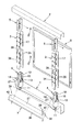
次に、添付図面に示した実施形態に基づき、本発明を更に詳細に説明する。図1は間仕切装置の分解斜視図、図2〜図5はその各部の詳細を示し、図6〜図8はアジャスターを示し、図中符号1は地レール、2は天レール、3は支柱、4はアジャスター、5は天支持金具、6はパネル板、7はパネル支持体、8はドア枠をそれぞれ示している。 Next, the present invention will be described in more detail based on the embodiments shown in the accompanying drawings. 1 is an exploded perspective view of the partition device, FIGS. 2 to 5 show details of each part, FIGS. 6 to 8 show adjusters, in which 1 is a ground rail, 2 is a ceiling rail, 3 is a support, 4 is an adjuster, 5 is a top support bracket, 6 is a panel plate, 7 is a panel support, and 8 is a door frame.
本実施形態の間仕切装置は、上方開放した断面略コ字形の地レール1の内部に、支柱3の下端部に装着したアジャスター4を配置するとともに、該支柱3の上端部に上下方向に調節可能に設けられた天支持金具5を、下方開放した断面略コ字形の天レール2の内部に嵌合して、該支柱3を立起状態に支持するとともに、間隔を隔てた両支柱3,3の表裏両面にパネル板6,6を取付けるものである。ここで、前記アジャスター4,4間に、従来のものと同様にパネル支持体7の両端部を連結し、隣接する両支柱3,3の表裏両面に係止具9,…等を用いてパネル板6の両側縁を係止するとともに、パネル板6の下端を前記パネル支持体7に載支する。また、適宜隣接する両支柱3.3にドア枠8を連結して図示しないドアパネルを取付け、あるいはガラス枠体を取付けてガラスパネルを支持することもある。
The partition device of the present embodiment has an
前記アジャスター4は、図1〜図8に示すように、前記支柱3の下端部に装着する受け部材10と、該受け部材10に螺合して前記地レール1内に載置するアジャスターボルト11とからなり、前記受け部材10は内部が中空の四角筒状で下部に前記アジャスターボルト11を鉛直に螺合する底面板12を有するとともに、前記地レール1に沿った方向と直交する二側面のうち、一側面にパネル板6の下端を載支するパネル支持体7や他の縦枠部材を支持する係止片13を一体的に突設し、他側面には前記係止片13と同じ高さに同じ機能の係止金具14を着脱自在に設け、更に四側面のうち何れか一側面に回転工具Dを挿入する縦長開口15を形成し、前記アジャスターボルト11の上端には回転工具Dを係合する係合部16を形成し、前記支柱3の下端部を前記受け部材10に装着した状態で前記縦長開口15が露出するようになっている。
As shown in FIGS. 1 to 8, the
ここで、前記アジャスター4の受け部材10は、前記係止片13の上方の側面に前記縦長開口15を形成したものであり、前記支柱3は、図1、図3及び図4に示すように、断面略C字形の杆体で一側面に縦方向に開口17を有するものであり、該支柱3の下端部を前記受け部材10に外嵌した際に、前記開口17から前記縦長開口15が露出するようにしている。
Here, the receiving
更に詳しくは、前記アジャスター4の受け部材10は、図6及び図7に示すように、スチール板を折曲形成したものであり、前記底面板12の両側から断面略コ字形の側面部18,19を直角に折曲して両側面部18,19で上端が開放した四角筒状の本体部を形成し、一方の前記側面部18の中央面に前記係止片13を切り起こし形成するとともに、該係止片13を切り起こした穴を利用して前記縦長開口15を形成している。また、前記アジャスター4の受け部材10は、前記係止片13の両側に、上端が該係止片13の上面と同じ高さで前記支柱3の下端部を当止する突片20,20を切り起こし形成している。
More specifically, as shown in FIGS. 6 and 7, the receiving
前記底面板12の中央部には、上方へ向けてバーリング加工して前記アジャスターボルト11を螺合する螺孔21を形成し、前記係止片13は平面視略T字形であり、先端部の中央に孔22を形成し、前記縦長開口15の下部は前記係止片13を切り起こし形成したことにより横幅の広い部分を有し、この拡幅部23から受け部材10の内部を覗き込むことができ、該縦長開口15に傾斜状態で挿入したドライバー等の回転工具Dを、前記アジャスターボルト11の上端部の係合部16に係合させる作業が容易になる。また、前記両側面部18,19で、前後面に対応する上部にそれぞれ二つずつ半球状のダボ24,…を突設し、前記支柱3の下端部を外嵌した際に、支柱3の内面に圧接するようになっている。
A
そして、前記アジャスター4の受け部材10は、前記係止片13を突設した側面とは反対側の側面に、横長のスリット孔25とその上方に螺孔若しくは下穴26を形成してなり、前記係止金具14は、水平な係止板27と垂直な取付板28とを有するL字形部材で、該取付板28の下端に前記係止板27と反対側に係合片29を折曲形成するとともに、前記取付板28に通孔30を形成してなり、前記係止金具14の係合片29を前記受け部材10のスリット孔25に係合し、前記取付板28を側面に接合し、前記通孔30から挿入したネジ若しくはタッピンネジ31を前記螺孔若しくは下穴26に螺合して、前記係止金具14を受け部材10に取付ける。ここで、前記係止板27は、平面視略T字形であり、先端部の中央に孔32を形成するとともに、前記取付板28の上端両側に、該取付板28の上面と面一になるように当止片33,33を上向き突設している。
The receiving
前記支柱3は、断面略コ字形の本体杆34の開口縁の両側から対向する方向に補強片35,35を折曲形成した断面略C字形であり、前記補強片35,35の上下端部を切欠するとともに、反対側の本体杆34の側面板36の上下端部を切欠し、切欠縁が統一高さとなっている。そして、この支柱3の下端部を前記受け部材10に外挿すると、前記補強片35,35の下端が前記受け部材10の突片20,20に当接するとともに、前記側面板36の下端が前記係止金具14の当止片33,33に当接する。ここで、前記支柱3に対して左右逆に前記受け部材10を嵌着した場合には、前記補強片35,35の下端が前記係止金具14の当止片33,33に当接するとともに、前記側面板36の下端が前記受け部材10の突片20,20に当接する。従って、前記係止金具14を前記受け部材10に取付けない場合でも、前記突片20,20に支柱3の補強片35,35の下端か、あるいは側面板36の下端が当接するので、該支柱3に掛かる荷重を確実にアジャスター4で支持することができる。
The
前記受け部材10は、前記底面板12の両側から断面略コ字形の側面部18,19を直角に折曲して四角筒状の本体部を形成したものであるが、両側面部18,19を直角に折曲しても弾性復元によって完全に接合することはできない。つまり、両側面部18,19の上端部は若干開いた状態となり、必然的に内外への弾力性を備えている。そのため、前記支柱3の下端部を前記受け部材10の上部に外挿する際に、前記側面部18,19を接近する方向に変形させながら弾性的に嵌合するので、前記ダボ24,…の存在と相俟ってガタツキのない連結ができる。
The receiving
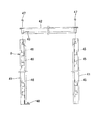
前記パネル支持体7は、図1、図2、図3及び図5に示すように、断面略ハット形であり、即ち下方開放した断面略コ字形の杆体37の前後両側に水平に受板38,38を外向きに形成したものであり、前記杆体37の両端部を前記アジャスター4の係止片13と、アジャスター4に取付けた係止金具14の係止板27に載置するとともに、タッピンネジ39,39を杆体37の通孔40,40に通してそれぞれ係止片13の孔22と係止板27の孔32に螺合する。
As shown in FIGS. 1, 2, 3 and 5, the
間仕切装置を施工する場合、前記支柱3の下端部に前記アジャスター4を装着した状態で、未施工側に前記支柱3の開口17とアジャスター4の縦長開口15を向けて前記地レール1と天レール2間に立設し、隣接する一方のアジャスター4の係止片13と他方のアジャスター4に取付けた係止金具14の係止板27に、前述のように前記パネル支持体7の両端部を連結する。前記パネル支持体7を隣接するアジャスター4,4間にわたって連結することにより、支柱3,3の間隔は正確に規定される。そして、両支柱3,3の表裏両面に前記係止具9,…を用いて前記パネル板6の裏面両側部を係止するとともに、該パネル板6の下端を前記パネル支持体7の受板38に載支する。ここで、前記パネル板6を支柱3,3に取付ける前、あるいは取付けた後に、支柱3の高さを調節する必要がある場合には、前記アジャスター4の縦長開口15から回転工具Dを挿入し、前記アジャスターボルト11の上端の係合部16に係合させて、該アジャスターボルト11を回転させて高さを微調節することができる。この支柱3の立設と、パネル支持体7の連結と、パネル板6の取付作業を、前記地レール1と天レール2に沿って順次行うのである。尚、前記パネル板6の支柱3への取付けは、全ての支柱3,…を、その間隔と高さを正確に調節して立設した後に、最後に行ってもよい。
When constructing a partitioning device, the
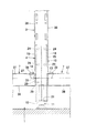
図9及び図10は、隣接する支柱3,3間にドア枠8を設ける場合を示している。前記ドア枠8は、縦枠41と上横枠42とからなっている。前記ドア枠8を設ける位置の両支柱3,3は、前記側面板36を設けた側が間口に面するように地レール1と天レール2間に立設する。ここで、前記地レール1は、ドア枠8を設ける空間には設けずに、床面のままとする。そして、間口左側(図9の左側)の支柱3に対しては、前記縦枠41の一側部を前記支柱3に外嵌した状態で、間口側から該縦枠41を貫通させた固定ネジ43,…を支柱3の側面板36に螺合して取付ける。一方、間口右側(図9の右側)の支柱3に対しては、前記縦枠41の一側部を前記支柱3に外嵌した状態で、前記支柱3の開口17から側面板36を貫通させた短い固定ネジ44,…を前記縦枠41の内部補強45,…に螺合して取付ける。ここで、左側の縦枠41も内部補強46,…が存在する位置で前記固定ネジ43を貫通させて支柱3にネジ止めする。そして、両縦枠41,41の上端間に上横枠42を上方から嵌合して、連結ネジ47,47で前記縦枠41,41に連結して、ドア枠8を形成する。一方の縦枠41の下端部とその直上の上横枠42の下面には、ヒンジ部材48,49を設け、図示しないドアパネルを開閉可能に支持できるようになっている。
9 and 10 show a case where the
この場合、前記支柱3の前記ドア枠8を設ける間口に面する側には、前記縦枠41を該支柱3に取付けるのに邪魔であれば、前記アジャスター4に係止金具14を取付けず、また前記係止金具14を積極的に利用して前記縦枠41を支持する構造の場合には前記アジャスター4に係止金具14を取付けて置けば良く、施工性や縦枠41の構造に応じて選択することができる。本実施形態では、前記係止金具14をアジャスター4に取付けていても、前記縦枠41に干渉しないので、該係止金具14を取付けたまま使用している。このような施工性における自由度は、前記アジャスター4の受け部材10の一側面に、前記係止金具14を着脱可能としたことによる。
In this case, on the side of the
前記支柱3の一側面側に前記パネル板6を支持するパネル支持体7以外の他の構成部材、例えば壁面に固定する壁面レールや戸当り枠材、二重ガラスの枠体等が位置する場合で、アジャスター4の受け部材10の側面に突起部があると干渉するような場合には、その側に前記係止金具14を取付けてない側面を向けることにより、干渉を防ぐことができる。そのような場合、従来は係止片13を切り落としたり、曲げたりして対処していたが、本発明では前記係止金具14を着脱自在としたことで、アジャスター4の設置位置に応じて係止金具14の要否を選択し、またアジャスター4の向きを変えることで容易に対応できるのである。
When a component other than the
1 地レール、 2 天レール、
3 支柱、 4 アジャスター、
5 天支持金具、 6 パネル板、
7 パネル支持体、 8 ドア枠、
9 係止具、 10 受け部材、
11 アジャスターボルト、12 底面板、
13 係止片、 14 係止金具、
15 縦長開口、 16 係合部、
17 開口、 18 側面部、
19 側面部、 20 突片、
21 螺孔、 22 孔、
23 拡幅部、 24 ダボ、
25 スリット孔、 26 下穴、
27 係止板、 28 取付板、
29 係合片、 30 通孔、
31 タッピンネジ、 32 孔、
33 当止片、 34 本体杆、
35 補強片、 36 側面板、
37 杆体、 38 受板、
39 タッピンネジ、 40 通孔、
41 縦枠、 42 上横枠、
43 固定ネジ、 44 固定ネジ、
45 内部補強、 46 内部補強、
47 連結ネジ、 48 ヒンジ部材、
49 ヒンジ部材、
D 回転工具。
1 ground rail, 2 top rail,
3 struts, 4 adjusters,
5 Top support bracket, 6 Panel board,
7 Panel support, 8 Door frame,
9 Locking
11 Adjuster bolt, 12 Bottom plate,
13 locking pieces, 14 locking brackets,
15 Longitudinal opening, 16 Engagement part,
17 opening, 18 side surface,
19 side parts, 20 protrusions,
21 holes, 22 holes,
23 Widening part, 24 Dowels,
25 slit holes, 26 pilot holes,
27 locking plate, 28 mounting plate,
29 engaging pieces, 30 through holes,
31 tapping screws, 32 holes,
33 Stopper, 34 Body 杆,
35 reinforcing pieces, 36 side plates,
37 housing, 38 receiving plate,
39 tapping screws, 40 through holes,
41 vertical frame, 42 upper horizontal frame,
43 fixing screws, 44 fixing screws,
45 internal reinforcement, 46 internal reinforcement,
47 connecting screws, 48 hinge members,
49 Hinge member,
D Rotary tool.
Claims (5)
Priority Applications (1)
| Application Number | Priority Date | Filing Date | Title |
|---|---|---|---|
| JP2012046951A JP5772664B2 (en) | 2012-03-02 | 2012-03-02 | Adjuster device in partition device |
Applications Claiming Priority (1)
| Application Number | Priority Date | Filing Date | Title |
|---|---|---|---|
| JP2012046951A JP5772664B2 (en) | 2012-03-02 | 2012-03-02 | Adjuster device in partition device |
Publications (2)
| Publication Number | Publication Date |
|---|---|
| JP2013181348A JP2013181348A (en) | 2013-09-12 |
| JP5772664B2 true JP5772664B2 (en) | 2015-09-02 |
Family
ID=49272211
Family Applications (1)
| Application Number | Title | Priority Date | Filing Date |
|---|---|---|---|
| JP2012046951A Active JP5772664B2 (en) | 2012-03-02 | 2012-03-02 | Adjuster device in partition device |
Country Status (1)
| Country | Link |
|---|---|
| JP (1) | JP5772664B2 (en) |
Families Citing this family (4)
| Publication number | Priority date | Publication date | Assignee | Title |
|---|---|---|---|---|
| JP6478475B2 (en) * | 2014-04-15 | 2019-03-06 | 株式会社竹中工務店 | Wall-like member support structure |
| JP6511966B2 (en) * | 2015-05-29 | 2019-05-15 | 株式会社イトーキ | Door frame mounting device for partition panel |
| JP6511967B2 (en) * | 2015-06-01 | 2019-05-15 | 株式会社イトーキ | Mounting device for adjuster support member on door frame |
| CN113684951B (en) * | 2021-08-09 | 2022-08-12 | 广州康普顿至高建材有限公司 | Concatenation formula cuts off |
Family Cites Families (7)
| Publication number | Priority date | Publication date | Assignee | Title |
|---|---|---|---|---|
| US4716699A (en) * | 1986-01-17 | 1988-01-05 | Rostec Industries | Wall panels with single load-bearing connector posts |
| JPH0684643B2 (en) * | 1987-03-14 | 1994-10-26 | コクヨ株式会社 | Movable partition wall |
| JPH063050Y2 (en) * | 1988-12-22 | 1994-01-26 | 株式会社イトーキクレビオ | Supporting device for columns in partitions |
| JPH07331775A (en) * | 1994-06-03 | 1995-12-19 | Kokuyo Co Ltd | Partition |
| JP2969442B2 (en) * | 1996-12-24 | 1999-11-02 | 株式会社岡村製作所 | Adjustment device for strut in partitioning device |
| JPH10317551A (en) * | 1997-05-16 | 1998-12-02 | Itoki Crebio Corp | Wall surface panel device |
| JP3575447B2 (en) * | 2001-07-24 | 2004-10-13 | 株式会社イトーキクレビオ | Wall panel equipment |
-
2012
- 2012-03-02 JP JP2012046951A patent/JP5772664B2/en active Active
Also Published As
| Publication number | Publication date |
|---|---|
| JP2013181348A (en) | 2013-09-12 |
Similar Documents
| Publication | Publication Date | Title |
|---|---|---|
| US9377040B2 (en) | Manufacture and method for forming structures and the structures resulting therefrom | |
| KR100827716B1 (en) | Bracket for window and door frames | |
| JP5772664B2 (en) | Adjuster device in partition device | |
| JP2012132296A (en) | Attachment structure of glass panel | |
| JP6299163B2 (en) | Connecting device in seismic partitioning device | |
| JP2016223174A (en) | Brace fixing device for partition panel | |
| JP6511966B2 (en) | Door frame mounting device for partition panel | |
| JP5286525B2 (en) | Cylindrical strut connection structure | |
| JP2014051860A (en) | Earthquake-resistant partition panel | |
| JP2018031178A (en) | Ceiling joist fitting device | |
| JP6497219B2 (en) | Adjuster device for partition panel | |
| JP2018071327A (en) | Partition device | |
| JP6229495B2 (en) | Seismic divider | |
| JP6299161B2 (en) | Panel plate locking device in earthquake-resistant partitioning device | |
| JP2021161739A (en) | Jig for wall connection and outer wall panel member provided with the jig | |
| JP2017210797A (en) | Panel connection structure | |
| JP5176207B2 (en) | Glass mounting structure for glass panels | |
| JP2008069584A (en) | Fitting structure of cover plate for partition wall corner part | |
| JP2016223171A (en) | Deflection prevention device for partition panel | |
| JP2016223170A (en) | Deflection prevention device for partition panel | |
| JP2008008112A (en) | Partition wall | |
| JP4108079B2 (en) | Shelf support structure of assembly house | |
| JP6511967B2 (en) | Mounting device for adjuster support member on door frame | |
| JP4367144B2 (en) | Mounting structure of outer wall panel for protruding corner | |
| JP2016223172A (en) | Cross rail support device for partition panel |
Legal Events
| Date | Code | Title | Description |
|---|---|---|---|
| A621 | Written request for application examination |
Free format text: JAPANESE INTERMEDIATE CODE: A621 Effective date: 20141227 |
|
| A977 | Report on retrieval |
Free format text: JAPANESE INTERMEDIATE CODE: A971007 Effective date: 20150424 |
|
| TRDD | Decision of grant or rejection written | ||
| A01 | Written decision to grant a patent or to grant a registration (utility model) |
Free format text: JAPANESE INTERMEDIATE CODE: A01 Effective date: 20150602 |
|
| A61 | First payment of annual fees (during grant procedure) |
Free format text: JAPANESE INTERMEDIATE CODE: A61 Effective date: 20150615 |
|
| R150 | Certificate of patent or registration of utility model |
Ref document number: 5772664 Country of ref document: JP Free format text: JAPANESE INTERMEDIATE CODE: R150 |
|
| S531 | Written request for registration of change of domicile |
Free format text: JAPANESE INTERMEDIATE CODE: R313531 |
|
| R350 | Written notification of registration of transfer |
Free format text: JAPANESE INTERMEDIATE CODE: R350 |