JP6554101B2 - Method of laying foundations of offshore wind turbines and template used for laying foundations of offshore wind turbines - Google Patents
Method of laying foundations of offshore wind turbines and template used for laying foundations of offshore wind turbines Download PDFInfo
- Publication number
- JP6554101B2 JP6554101B2 JP2016537137A JP2016537137A JP6554101B2 JP 6554101 B2 JP6554101 B2 JP 6554101B2 JP 2016537137 A JP2016537137 A JP 2016537137A JP 2016537137 A JP2016537137 A JP 2016537137A JP 6554101 B2 JP6554101 B2 JP 6554101B2
- Authority
- JP
- Japan
- Prior art keywords
- template
- suction bucket
- suction
- bucket
- seabed
- Prior art date
- Legal status (The legal status is an assumption and is not a legal conclusion. Google has not performed a legal analysis and makes no representation as to the accuracy of the status listed.)
- Active
Links
- 238000000034 method Methods 0.000 title claims description 55
- XLYOFNOQVPJJNP-UHFFFAOYSA-N water Substances O XLYOFNOQVPJJNP-UHFFFAOYSA-N 0.000 claims description 45
- 230000035515 penetration Effects 0.000 claims description 16
- 238000005086 pumping Methods 0.000 claims description 6
- 230000004044 response Effects 0.000 claims description 2
- 230000008878 coupling Effects 0.000 claims 1
- 238000010168 coupling process Methods 0.000 claims 1
- 238000005859 coupling reaction Methods 0.000 claims 1
- 238000009434 installation Methods 0.000 description 19
- 230000005484 gravity Effects 0.000 description 6
- 238000010586 diagram Methods 0.000 description 5
- 230000009471 action Effects 0.000 description 2
- 238000005553 drilling Methods 0.000 description 2
- 238000003780 insertion Methods 0.000 description 2
- 230000037431 insertion Effects 0.000 description 2
- 239000002689 soil Substances 0.000 description 2
- 229910000831 Steel Inorganic materials 0.000 description 1
- 230000008901 benefit Effects 0.000 description 1
- 230000005540 biological transmission Effects 0.000 description 1
- 230000008859 change Effects 0.000 description 1
- 238000010276 construction Methods 0.000 description 1
- 239000011440 grout Substances 0.000 description 1
- 230000005404 monopole Effects 0.000 description 1
- 238000012634 optical imaging Methods 0.000 description 1
- 230000000149 penetrating effect Effects 0.000 description 1
- 238000003825 pressing Methods 0.000 description 1
- 230000008569 process Effects 0.000 description 1
- 230000003014 reinforcing effect Effects 0.000 description 1
- 239000011435 rock Substances 0.000 description 1
- 239000004576 sand Substances 0.000 description 1
- 239000013049 sediment Substances 0.000 description 1
- 239000010959 steel Substances 0.000 description 1
- 230000003313 weakening effect Effects 0.000 description 1
Images


Classifications
-
- E—FIXED CONSTRUCTIONS
- E02—HYDRAULIC ENGINEERING; FOUNDATIONS; SOIL SHIFTING
- E02D—FOUNDATIONS; EXCAVATIONS; EMBANKMENTS; UNDERGROUND OR UNDERWATER STRUCTURES
- E02D7/00—Methods or apparatus for placing sheet pile bulkheads, piles, mouldpipes, or other moulds
-
- E—FIXED CONSTRUCTIONS
- E02—HYDRAULIC ENGINEERING; FOUNDATIONS; SOIL SHIFTING
- E02B—HYDRAULIC ENGINEERING
- E02B17/00—Artificial islands mounted on piles or like supports, e.g. platforms on raisable legs or offshore constructions; Construction methods therefor
- E02B17/02—Artificial islands mounted on piles or like supports, e.g. platforms on raisable legs or offshore constructions; Construction methods therefor placed by lowering the supporting construction to the bottom, e.g. with subsequent fixing thereto
-
- E—FIXED CONSTRUCTIONS
- E02—HYDRAULIC ENGINEERING; FOUNDATIONS; SOIL SHIFTING
- E02D—FOUNDATIONS; EXCAVATIONS; EMBANKMENTS; UNDERGROUND OR UNDERWATER STRUCTURES
- E02D13/00—Accessories for placing or removing piles or bulkheads, e.g. noise attenuating chambers
- E02D13/04—Guide devices; Guide frames
-
- E—FIXED CONSTRUCTIONS
- E02—HYDRAULIC ENGINEERING; FOUNDATIONS; SOIL SHIFTING
- E02D—FOUNDATIONS; EXCAVATIONS; EMBANKMENTS; UNDERGROUND OR UNDERWATER STRUCTURES
- E02D27/00—Foundations as substructures
- E02D27/10—Deep foundations
- E02D27/12—Pile foundations
-
- E—FIXED CONSTRUCTIONS
- E02—HYDRAULIC ENGINEERING; FOUNDATIONS; SOIL SHIFTING
- E02D—FOUNDATIONS; EXCAVATIONS; EMBANKMENTS; UNDERGROUND OR UNDERWATER STRUCTURES
- E02D27/00—Foundations as substructures
- E02D27/10—Deep foundations
- E02D27/12—Pile foundations
- E02D27/16—Foundations formed of separate piles
-
- E—FIXED CONSTRUCTIONS
- E02—HYDRAULIC ENGINEERING; FOUNDATIONS; SOIL SHIFTING
- E02D—FOUNDATIONS; EXCAVATIONS; EMBANKMENTS; UNDERGROUND OR UNDERWATER STRUCTURES
- E02D27/00—Foundations as substructures
- E02D27/32—Foundations for special purposes
- E02D27/42—Foundations for poles, masts or chimneys
-
- E—FIXED CONSTRUCTIONS
- E02—HYDRAULIC ENGINEERING; FOUNDATIONS; SOIL SHIFTING
- E02D—FOUNDATIONS; EXCAVATIONS; EMBANKMENTS; UNDERGROUND OR UNDERWATER STRUCTURES
- E02D27/00—Foundations as substructures
- E02D27/32—Foundations for special purposes
- E02D27/52—Submerged foundations, i.e. submerged in open water
- E02D27/525—Submerged foundations, i.e. submerged in open water using elements penetrating the underwater ground
-
- E—FIXED CONSTRUCTIONS
- E02—HYDRAULIC ENGINEERING; FOUNDATIONS; SOIL SHIFTING
- E02D—FOUNDATIONS; EXCAVATIONS; EMBANKMENTS; UNDERGROUND OR UNDERWATER STRUCTURES
- E02D7/00—Methods or apparatus for placing sheet pile bulkheads, piles, mouldpipes, or other moulds
- E02D7/02—Placing by driving
-
- E—FIXED CONSTRUCTIONS
- E02—HYDRAULIC ENGINEERING; FOUNDATIONS; SOIL SHIFTING
- E02B—HYDRAULIC ENGINEERING
- E02B17/00—Artificial islands mounted on piles or like supports, e.g. platforms on raisable legs or offshore constructions; Construction methods therefor
- E02B2017/0039—Methods for placing the offshore structure
- E02B2017/0043—Placing the offshore structure on a pre-installed foundation structure
-
- E—FIXED CONSTRUCTIONS
- E02—HYDRAULIC ENGINEERING; FOUNDATIONS; SOIL SHIFTING
- E02B—HYDRAULIC ENGINEERING
- E02B17/00—Artificial islands mounted on piles or like supports, e.g. platforms on raisable legs or offshore constructions; Construction methods therefor
- E02B2017/0091—Offshore structures for wind turbines
-
- E—FIXED CONSTRUCTIONS
- E02—HYDRAULIC ENGINEERING; FOUNDATIONS; SOIL SHIFTING
- E02D—FOUNDATIONS; EXCAVATIONS; EMBANKMENTS; UNDERGROUND OR UNDERWATER STRUCTURES
- E02D2220/00—Temporary installations or constructions
-
- E—FIXED CONSTRUCTIONS
- E02—HYDRAULIC ENGINEERING; FOUNDATIONS; SOIL SHIFTING
- E02D—FOUNDATIONS; EXCAVATIONS; EMBANKMENTS; UNDERGROUND OR UNDERWATER STRUCTURES
- E02D2600/00—Miscellaneous
- E02D2600/10—Miscellaneous comprising sensor means
Landscapes
- Engineering & Computer Science (AREA)
- General Engineering & Computer Science (AREA)
- Civil Engineering (AREA)
- Structural Engineering (AREA)
- Life Sciences & Earth Sciences (AREA)
- General Life Sciences & Earth Sciences (AREA)
- Mining & Mineral Resources (AREA)
- Paleontology (AREA)
- Mechanical Engineering (AREA)
- Foundations (AREA)
- Underground Or Underwater Handling Of Building Materials (AREA)
- Wind Motors (AREA)
Description
本発明は、包括的には、洋上風力タービンの基礎を設置する方法及び洋上風力タービンの基礎を設置するのに用いるテンプレートに関する。 The present invention relates generally to a method of laying an offshore wind turbine foundation and a template for use in laying an offshore wind turbine foundation.
風力発電設備、洋上プラットフォーム、沈水式水力駆動タービン(submerged water-driven turbine)設備等のような洋上施設の設置の際、多くの場合、複数の柱又はパイル(杭)を海底に打ち込むことによって基礎を設ける。例えば、風力設備の支持構造物は、地中の基礎に結合することができる円筒形のタワー部分によって構成されることが多い。検討する洋上施設の種類に関わらず、洋上施設の安定性は、基礎によって与えられる支持に大きく依存する。風力設備等の洋上施設のための基礎は、設置場所における水深の徹底的な分析及び設置場所の海底の土壌条件に基づいて計画及び建設される。風力設備の場合、ナセルの重量、回転速度等を含むタービンの仕様等の更なる問題が考慮される。したがって、洋上基礎の計画及び建設は、基礎の安定性をリスクにさらさないようにあらゆる不具合を排除する必要がある複雑な作業であることが容易にわかる。 When installing offshore facilities such as wind power installations, offshore platforms, submerged water-driven turbines, etc., the foundation is often driven by driving multiple columns or piles into the seabed. Is provided. For example, wind turbine support structures are often constituted by cylindrical tower portions that can be coupled to a foundation in the ground. Regardless of the type of offshore facility considered, the stability of the offshore facility depends largely on the support provided by the foundation. Foundations for offshore installations, such as wind power installations, are planned and constructed based on a thorough analysis of the water depth at the installation site and the soil conditions of the seabed at the installation site. In the case of wind power installations, further issues such as turbine specifications including nacelle weight, rotational speed etc are taken into account. Thus, it is readily apparent that offshore foundation planning and construction is a complex task that needs to eliminate any failure so as not to put the stability of the foundation at risk.
通常、重力着底式基礎及びジャケット式基礎の2つのタイプの基礎が使用される。従来の重力着底式基礎は、自重によって適所に保持される円筒形/円錐形のコンクリート製支持構造物を含む。ジャケット式基礎は、通常、補強材(braces)により互いに連結される4つの脚部を備える鋼製構造物である。一般的に、脚部は、海底の土壌に打ち込まれるパイルにグラウト(grout)が詰められる。ジャケット式基礎は、重力着底式基礎に比べて設置場所への移送が簡単である。 Usually, two types of foundations are used: gravity grounded foundations and jacketed foundations. Conventional gravity grounded foundations include a cylindrical / conical concrete support structure held in place by its own weight. A jacketed foundation is usually a steel structure with four legs connected together by braces. Generally, the legs are filled with grout in piles that are driven into the seabed soil. The jacket-type foundation is easier to transfer to the place of installation than the gravity bottomed foundation.
更に、重力着底式基礎は、海底が岩盤である浅い沿岸におけるプロジェクトの場合のより小さい風力タービンに対して主として用いられてきた。より大きいタービン及びより深い水深の場合、一般的にはジャケット式基礎の方が重力着底式基礎よりも好ましい。 In addition, gravity ground foundations have been used primarily for smaller wind turbines in the case of projects on shallow coasts where the seabed is rock. For larger turbines and deeper water depths, jacketed foundations are generally preferred over gravity grounded foundations.
安定性を確保するために、海底におけるパイルの設置は入念に計画され、パイルは所定の設置計画にしたがって設置される。ここでは、基礎の信頼性は、所定の設置計画の質に加えて、所定の設置計画の正確な実現によるものであり、計画から逸脱することは、基礎の構造の弱体化につながる場合があるため、パイルの正確な位置合わせは非常に重要である。特に、第1のパイルに対する第2のパイルの相対位置及び鉛直の基準方向に対するパイルの向きは、基礎の安定性を決定する際に基づく重要なパラメーターである。これらのパラメーターに関して、位置がずれていると基礎にかかる荷重を安全に保持できない場合があるので、位置合わせを達成するべきである。 In order to ensure stability, the installation of piles on the sea floor is carefully planned and the piles are installed according to a predetermined installation plan. Here, the reliability of the foundation is in addition to the quality of the predetermined installation plan due to the exact realization of the predetermined installation plan, and deviation from the plan may lead to a weakening of the structure of the foundation Therefore, accurate alignment of the pile is very important. In particular, the relative position of the second pile to the first pile and the orientation of the pile relative to the vertical reference direction are important parameters based on which to determine the stability of the foundation. With respect to these parameters, alignment should be achieved because the load on the foundation may not be safely held if it is misaligned.
パイルを設置する際の位置合わせは、従来、テンプレートによって達成され、このテンプレートにしたがって、幾何学的パターンのパイルを海底に設置することができる。しかし、海底の設置場所が平坦でない可能性があるため、テンプレートが基準レベル位置、通常は水平レベルから逸脱するレベル位置をとることによってパイルの位置ずれが起こり得る。 Alignment when installing the pile is conventionally achieved by means of a template, according to which a pile of geometrical patterns can be installed on the seabed. However, pile placement may occur due to the template taking a reference level position, usually a level position deviating from the horizontal level, as the installation location on the seabed may not be flat.
特許文献1は、ジャッキアッププラットフォームによって位置決めされる洋上基礎を提供するフレーム付きテンプレートを示している。ここでは、フレーム付きテンプレートは、海底に向かってスパッドポール(spud pole)に沿って降下され、パイルはテンプレートのスリーブガイド部材を通して海底に打ち込まれる。しかし、ジャッキアッププラットフォームを設置場所に設置するには、スパッドポールを海底に固定する必要があるため、パイルを迅速に設置することは不可能である。更に、特に非常に深いところ及び海の荒い状態では、ジャッキアッププラットフォームの使用は可能でない場合があり、同時に、フレーム付きテンプレートの向きの正確さは、スパッドポールの向きに依存するため、スパッドポールの位置ずれはフレーム付きテンプレートの位置ずれを引き起こす。 U.S. Patent No. 6,057,049 shows a framed template that provides an offshore foundation positioned by a jack-up platform. Here, the framed template is lowered along the spud pole towards the seabed and the pile is driven into the seabed through the sleeve guide members of the template. However, in order to install the jack-up platform at the installation site, it is necessary to fix the spud pole to the seabed, so it is impossible to install the pile quickly. In addition, particularly in very deep and rough seas, the use of a jack-up platform may not be possible, and at the same time the accuracy of the orientation of the framed template depends on the orientation of the spud pole, so The misalignment causes misalignment of the framed template.
特許文献2は、プラットフォームを水平位置に調整し、柱又はパイルを海底の所定の位置に固定することができる、削孔機及び伸縮式脚部を備える沈水式プラットフォームを示している。しかし、プラットフォームは、海底に対する移動を起こす場合があり、それにより、所定の設置場所に対するプラットフォームの位置ずれが起こる場合がある。 US Pat. No. 5,956,015 shows a submersible platform comprising a drilling machine and telescopic legs, which can adjust the platform in a horizontal position and fix the columns or piles in place on the seabed. However, the platform may cause movement relative to the seabed, which may result in misalignment of the platform with respect to the predetermined installation location.
特許文献3は、海底に水中削孔ベースプレートを設置する方法を示している。 Patent Document 3 shows a method of installing an underwater drilling base plate on the seabed.
したがって、本発明の目的は、洋上基礎を設置する際のパイルの正確な位置合わせを確実にすることである。 Accordingly, it is an object of the present invention to ensure the correct alignment of piles when installing offshore foundations.
本発明の一態様において、洋上風力タービンの基礎を設置する方法が提供される。本発明の例示的な一実施形態において、本方法は、パイルを受けるように構成されている少なくとも1つの中空のガイド部材と、少なくとも1つのサクションバケット(suction bucket)と、少なくとも1つの中空のガイド部材及び少なくとも1つのサクションバケットに結合するフレーム体とを備えるテンプレートを準備することを含むことができる。本方法は、テンプレートを海底に配置することと、サクションバケットを海底に打ち込むために少なくとも1つのサクションバケットに負圧を与えることと、フレーム体を海底に対して水平にするように少なくとも1つのサクションバケットの根入れ深さを調節するために少なくとも1つのサクションバケットに与えられる負圧を制御することとを更に含むことができる。更に、本方法は、中空のガイド部材内にパイルを配置してパイルを海底に設置することを含む。 In one aspect of the present invention, a method for installing a foundation for an offshore wind turbine is provided. In an exemplary embodiment of the invention, the method includes at least one hollow guide member configured to receive a pile, at least one suction bucket, and at least one hollow guide. Preparing a template comprising a member and a frame body coupled to at least one suction bucket may be included. The method comprises placing the template on the seabed, applying negative pressure to the at least one suction bucket to drive the suction buckets into the seabed, and at least one suction so as to level the frame body relative to the seabed. Controlling the negative pressure applied to the at least one suction bucket to adjust the penetration depth of the bucket. Additionally, the method includes placing the pile in the hollow guide member and placing the pile on the seabed.
このようにして、テンプレートは海底の固定位置に解放可能に固定することができ、同時に、少なくとも1つのサクションバケットの根入れ深さを調整することによってテンプレートを水平にすることができ、それにより、正確な位置合わせが確実になる。 In this way, the template can be releasably fixed in a fixed position on the seabed, and at the same time the template can be leveled by adjusting the depth of penetration of at least one suction bucket, thereby Accurate alignment is ensured.
本発明の更なる例示的な一実施形態において、本方法は、フレーム体の所定の基準レベルに対するフレーム体の傾斜を求めることと、少なくとも1つのサクションバケットに与えられる負圧を調整することとを更に含むことができる。したがって、少なくとも1つのサクションバケットの挿入を制御して行うことができ、それにより、正確な位置合わせを達成することができる。 In a further exemplary embodiment of the present invention, the method comprises determining the inclination of the frame body relative to a predetermined reference level of the frame body and adjusting the negative pressure applied to the at least one suction bucket. It can further include. Thus, the insertion of at least one suction bucket can be controlled and thereby an accurate alignment can be achieved.
本発明の更なる例示的な一実施形態において、本方法は、フレーム体を水平にするように、少なくとも1つのサクションバケットの根入れ深さを決定することを更に含むことができる。このようにして、テンプレートがさらされる海底の固有の状態に関わらず、フレームの非常に正確な水平化(leveling)を簡単かつ確実に達成することができる。 In a further exemplary embodiment of the present invention, the method may further comprise determining the penetration depth of the at least one suction bucket so as to level the frame body. In this way, very accurate leveling of the frame can be achieved easily and reliably regardless of the inherent state of the seabed to which the template is exposed.
本発明の更なる例示的な一実施形態において、本方法は、負圧を決定された根入れ深さに応じて制御することを更に含むことができる。このようにして、海底にテンプレートを確実に固定する間、直接的かつ迅速な水平化を達成することができる。 In a further exemplary embodiment of the present invention, the method may further include controlling the negative pressure as a function of the determined penetration depth. In this way, a direct and rapid leveling can be achieved while securely fixing the template to the seabed.
本発明の更なる例示的な一実施形態において、負圧を制御することは、フレーム体の傾斜を連続的に感知することと、感知された傾斜に応じて少なくとも1つのサクションバケットに与えられる負圧を調整することとを含むことができる。このようにして、フィードバック結合された制御を実施することができる。 In a further exemplary embodiment of the present invention, controlling the negative pressure comprises continuously sensing the tilt of the frame body and applying a negative to the at least one suction bucket in response to the sensed tilt. Adjusting the pressure. In this way, feedback coupled control can be implemented.
本発明の更なる例示的な一実施形態において、複数のサクションバケットを設けることができ、本方法は、各サクションバケットを個別のポンプシステムに接続することを更に含むことができる。このようにして、テンプレートの確実な固定及び水平化を達成することができる。 In a further exemplary embodiment of the present invention, a plurality of suction buckets may be provided, and the method may further include connecting each suction bucket to a separate pump system. In this way, reliable fixing and leveling of the template can be achieved.
本発明の更なる例示的な一実施形態において、複数のサクションバケットが設けられ、本方法は、複数のサクションバケットを、単一のポンプを有するポンプシステムに接続することを更に含むことができる。このようにして、単一のポンプを備えるポンプシステムの単純な構成によって、固定及び水平化を達成することができる。 In a further exemplary embodiment of the present invention, a plurality of suction buckets are provided, and the method may further include connecting the plurality of suction buckets to a pump system having a single pump. In this way, fixing and leveling can be achieved by a simple configuration of the pump system with a single pump.
本発明の更なる例示的な一実施形態において、ポンプシステムは、各サクションバケットに個々に負圧を与えるように構成することができる。このようにして、単一のポンプに関してテンプレートの確実な固定及び水平化を達成することができる。 In a further exemplary embodiment of the present invention, the pump system can be configured to apply a negative pressure to each suction bucket individually. In this way, reliable fixation and leveling of the template can be achieved with respect to a single pump.
本発明の更なる例示的な一実施形態において、各サクションバケットの弁部材を制御して、各サクションバケットに与えられる負圧を個々に制御することを含むことができ、ポンプは弁部材に結合される。このようにして、複数のサクションバケットは単一のポンプによって確実に制御することができる。 In a further exemplary embodiment of the present invention, the method may include controlling the valve member of each suction bucket to individually control the negative pressure applied to each suction bucket, the pump being coupled to the valve member Is done. In this way, the plurality of suction buckets can be reliably controlled by a single pump.
本発明の更なる例示的な一実施形態において、負圧を制御することは、少なくとも1つのサクションバケットから汲み出される水の量及び流量のうちの少なくとも一方を制御することを含むことができる。このようにして、海底における少なくとも1つのサクションバケットの所定の根入れ深さを簡単に調整することができる。 In a further exemplary embodiment of the present invention, controlling the negative pressure can include controlling at least one of the amount and flow rate of water pumped from the at least one suction bucket. In this way, the predetermined penetration depth of at least one suction bucket at the seabed can be easily adjusted.
本発明の別の態様において、洋上基礎を設置するのに用いるテンプレートが提供される。本発明の例示的な一実施形態において、テンプレートは、パイルを受ける少なくとも1つの中空のガイド部材と、少なくとも1つのサクションバケットと、少なくとも1つの中空のガイド部材及び少なくとも1つのサクションバケットに結合するフレーム体とを備える。更に、テンプレートは、少なくとも1つのサクションバケットに圧力を与えるように構成されている制御手段を備える。 In another aspect of the present invention, a template for use in installing an offshore foundation is provided. In an exemplary embodiment of the invention, the template includes a frame coupled to at least one hollow guide member that receives the pile, at least one suction bucket, and at least one hollow guide member and at least one suction bucket. With body. Further, the template comprises control means configured to apply pressure to the at least one suction bucket.
このようにして、海底に迅速かつ解放可能に固定することが可能なテンプレートが提供される。 In this way, a template is provided that can be quickly and releasably secured to the seabed.
本発明の更なる例示的な一実施形態において、テンプレートは、第1の圧力感知装置及び/又は第2の圧力感知装置を更に備えることができ、第1の圧力感知装置は、少なくとも1つのサクションバケットのうちの1つに結合され、サクションバケット内の圧力を感知するように構成されており、第2の圧力感知装置は、テンプレートの所定の位置において周囲の水圧を感知するように構成されている。このようにして、傾斜及び/又は根入れ深さを簡単に確定することができる。 In a further exemplary embodiment of the present invention, the template can further comprise a first pressure sensing device and / or a second pressure sensing device, the first pressure sensing device comprising at least one suction. Coupled to one of the buckets and configured to sense pressure in the suction bucket, the second pressure sensing device is configured to sense ambient water pressure at a predetermined position of the template Yes. In this way, the inclination and / or depth of penetration can be easily determined.
本発明の更なる例示的な一実施形態において、テンプレートのフレーム体は、フレーム体が多角形状になるように連結されるフレーム部材によって形成することができる。このようにして、所定のパターンにしたがってパイルの設置を実施するために有利な形状を有するテンプレートを提供することができる。 In a further exemplary embodiment of the present invention, the frame body of the template may be formed by a frame member connected so that the frame body is in a polygonal shape. In this way, it is possible to provide a template having an advantageous shape for carrying out pile installation according to a predetermined pattern.
本発明の更なる例示的な一実施形態において、テンプレートは、少なくとも3つのサクションバケットを備えることができ、少なくとも3つのサクションバケットのそれぞれは、1つのフレーム部材に機械的に結合される。このようにして、テンプレートの確実な固定及び水平化を迅速に達成することができる。 In a further exemplary embodiment of the present invention, the template can comprise at least three suction buckets, each of the at least three suction buckets being mechanically coupled to one frame member. In this way, reliable fixing and leveling of the template can be achieved quickly.
以下、添付図面を参照しながら本発明を記載する。 The present invention will now be described with reference to the accompanying drawings.
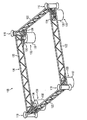
図1a、図1b及び図1cにおいて、本発明の例示的な一実施形態に係るテンプレート100を記載する。図1aに示すテンプレート100は、略四角形のフレーム体120によって形成される。フレーム体120は、四角形の辺にしたがって構成されたフレーム部材122によって設けられる。フレーム部材122は、四角形のフレーム体120の角部に配置された中空のガイド部材110に結合されている。フレーム部材122は、中空のガイド部材110を互いに対して所定の固定位置に配置するように構成することができる。中空のガイド部材110は、フレーム体120の角部に配置され、隣り合うフレーム部材122を接続するものとして示しているが、本発明の限定は意図していない。代替的には、中空のガイド部材110は、例えば、フレーム部材122に沿った異なる位置においてフレーム部材122に取り付けられてもよい。本明細書の或る特定の例において、各中空のガイド部材110は、それぞれのフレーム部材122の中央部に配置することができる。
In FIG. 1a, FIG. 1b and FIG. 1c, a
少なくとも1つの中空のガイド部材110が取り付けられたフレーム体を実施するのに、任意の他の適した幾何形状、例えば三角形又は一般に多角形を考慮することができることが当業者には理解される。
It will be appreciated by those skilled in the art that any other suitable geometry, such as a triangle or generally a polygon, can be considered to implement a frame body with attached at least one
図1aに示すように、フレーム部材122は、各フレーム部材122を補強する横梁部材を有する2つの平行な梁によって形成される。しかしながら、このことは本発明にいかなる限定も与えず、フレーム部材は、補強用横梁部材を伴って又は伴わずに、多角幾何形状の辺に相当する1つ又は2つよりも多い梁で実施することができる。
As shown in FIG. 1 a, the
図1aに示すように、テンプレート100は4つのサクションバケット130を更に備える。4つのサクションバケット130は、各サクションバケット130が中空のガイド部材110のうちの1つに対置されるように、フレーム体120によって囲まれる領域内のテンプレート100の各角部に配置される。図1aは4つのサクションバケット130を明示しているが、代替的には、任意の他の数のサクションバケット、一般に少なくとも1つのサクションバケットを設けてもよいことが当業者には理解される。例えば、2つのサクションバケット130を、対向する位置においてフレーム体120に結合することができる。別の代替例では、3つのサクションバケットをフレーム体120に結合することができる。代替的には、サクションバケットは、フレーム部材122に沿った各フレーム部材122の中央部に近い位置、すなわちフレーム部材122に沿った2つの中空のガイド部材110の中間の位置等、角部から離れた位置に配置してもよいことが当業者には理解される。
As shown in FIG. 1 a, the
各サクションバケット130は、片側(図1aの下側)に開口を有する円筒形のバケット132によって実質的に設けられる。サクションバケット130の上側には、上部部材136が取り付けられている。上部部材136は横梁122に結合され、サクションバケット130は、例えば図1aに示す2つのフレーム部材122等、中空のガイド部材110及び少なくとも1つのフレーム部材122のうちの少なくとも一方と結合する。代替的には、バケット132は、中空のガイド部材110に直接結合するか、又はサクションバケット130をフレーム体120に結合するようにフレーム部材122に直接結合してもよい。
Each
加えて又は代替的には、各サクションバケット130の上部部材136は、ポンプシステムと接続するように構成してもよい。本明細書のいくつかの特定の例示的な例において、上部部材136は、サクションバケット130をポンプシステム(図示せず)のホースに接続するのに用いる弁部材(図示せず)を備えてもよい。或る特定の例示的な例によれば、弁部材は、与える圧力を制御する手段に相当することができる。一般に、サクションバケットへ与える圧力を制御することができるとともに所定の圧力を調整することができるように、サクションバケットに圧力を与える場合の制御動作をもたらすように構成された任意の既知の装置を使用することができる。したがって、代替的には、サクションバケットは、例えばホース等のいくつかの接続手段によって圧力容器に接続してもよく、例えば、この容器の弁部材によって、又は圧力容器からの圧力放出及び/又は圧力容器からサクションバケットへの圧力伝達の制御に好適な任意の他の手段によって、いくつかの制御手段を呈することができる。
In addition or alternatively, the
いくつかの例示的な例において、上部部材136には、バケット132内側の圧力及びバケット外側の圧力、すなわち周囲の水圧のうちの少なくとも一方を感知する圧力感知装置を設けることができる。少なくとも2つのサクションバケットの位置での周囲の水圧を比較することで、フレーム体120の傾斜を求めることができることが当業者には理解される。代替的には、サクションバケット130の地点に、及び/又はフレーム部材120の地点に若しくはフレーム部材120内に、及び/又は中空のガイド手段110の地点に又は中空のガイド手段110内に、気泡水準感知装置を設けることができる。気泡水準感知装置、ジャイロメーターに基づくレベル感知装置、レーザー等に基づく機械的手段によって、全般的な水準感知装置を設けることができることが当業者には理解される。異なる位置でフレームに取り付けられた、空気が充填されたバルーンであって、これらのバルーンを水上に浮遊させた場合、各バルーンに取り付けられたロープの長さを比較する、バルーンを用いることも更に可能である。このことは本発明にいかなる限定も与えず、他の技法を用いて水準感知を達成することができることが当業者には理解される。
In some illustrative examples, the
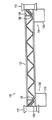
図1bは、フレーム部材120のうちの1つに沿ったテンプレート100の側面図を示している。サクションバケット130は、フレーム部材120の下側の梁においてフレーム部材120に取り付けられ、サクションバケット130、特に下側が開口しているバケット132が、海底(図示せず)に面するようになっている。バケット132の下側と中空のガイド部材110との下側との高さの差は、サクションバケット130の最大根入れ深さを示す。
FIG. 1 b shows a side view of the
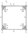
図1cは、本発明の或る特定の例示的な例を示す、図1aに示すテンプレート100の上面図を示している。
FIG. 1c shows a top view of the
例示的な一代替実施形態が図2に概略的に示されている。図2は、三角形のフレーム体220を備え、フレーム体220の各角部に中空のガイド部材210を有するテンプレート200を示している。フレーム体220は、中空のガイド部材210が結合されたフレーム部材222によって実現される。更に、テンプレート200は、それぞれの中空のガイド部材210に対置した状態でフレーム体220にそれぞれ結合された3つのサクションバケット230を備える。3つの別個の点によって3つの次元で平面が規定され、図2に示す実施形態は、テンプレート200の直接かつ容易な位置合わせを高精度に可能にすることが当業者には理解される。
An exemplary alternative embodiment is schematically illustrated in FIG. FIG. 2 shows a
中空のガイド部材210及び/又はサクションバケット230は、中空のガイド部材210及び/又はサクションバケット230が単一のフレーム部材222に沿って、例えば単一のフレーム部材222の中央の方にそれぞれ配置されるように、フレーム体220に結合することができることが留意される。
The
図2は3つのサクションバケットを示しているが、単に1つのサクションバケットを使用して、サクションバケットに対向するフレーム部材に対応した軸の回りにテンプレートを傾動させることで、位置合わせをもはや達成することができることが当業者には理解される。代替的には、2つのサクションバケットを使用して、サクションバケットに対向するフレーム部材にそれぞれ対応した2つの軸の回りでの傾動を達成することができる。この場合、図2に示す3つのサクションバケットのうちの1つ又は2つのサクションバケットを、海底に設置される足場部材(footing element)等の支持部材(図示せず)で置換することができる。 Although FIG. 2 shows three suction buckets, alignment is no longer achieved by tilting the template about an axis corresponding to the frame member opposite the suction buckets using only one suction bucket Those skilled in the art will appreciate that this is possible. Alternatively, two suction buckets can be used to achieve tilting about the two axes respectively corresponding to the frame members facing the suction buckets. In this case, one or two of the three suction buckets shown in FIG. 2 can be replaced with a support member (not shown) such as a footing element installed on the seabed.
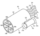
更なる例示的な一代替実施形態が図3に示されている。図3は、単一のフレーム部材320によって設けられるフレーム体によって結合された1つの中空のガイド部材310及び1つのサクションバケット330を備えるテンプレート300を示している。中空のガイド部材310は、円筒形のスリーブ部材312と、円筒形のスリーブ部材312のそれぞれの側に、外方に突出するフランジ部314a及び314bとを備えている。フランジ部314aによって、パイルの受容を容易にすることができることが当業者には理解される。
A further exemplary alternative embodiment is shown in FIG. FIG. 3 shows a
上記明示的な例では、サクションバケットは、チャンバー334a、334b、334c、334dを更に有する。これらのチャンバーは、壁部材336a、336b、336c、336dによって画定される。可能なチャンバー数は1つ以上とすることができることが当業者には理解される。1つよりも多い数のチャンバーが存在することは、解除可能な固定に加えて、テンプレート300の中心を通って延びるテンプレート300の縦方向寸法によって与えられる鉛直軸に対してテンプレート300を傾斜させることを可能にする。チャンバー334a、334b、334c、334dのそれぞれは、ホース352a、352b、352c、352dによって示されるようにポンプシステム350に接続することができる。
In the above explicit example, the suction bucket further comprises chambers 334a, 334b, 334c, 334d. These chambers are defined by
1つのサクションバケットを備える更なる一代替形態のテンプレートは、図3に示す実施形態からフレーム部材320をより長いフレーム部材で置換し、このより長いフレーム部材のサクションバケットが配置される端部とは反対側の端部に支持構造体を結合することによって得ることができる。この代替形態の中空のガイド部材は、このより長いフレーム部材の長さに亘って、このより長いフレーム部材に結合することができる。この代替的な実施形態のサクションバケットに関しては、1つのチャンバーを有するサクションバケットが好ましい。この場合、サクションバケットを海底に打ち込むことによって水平化を得ることができることが当業者には理解される。ここでは、サクションバケットの根入れ深さを増大することで、サクションバケットに向かっての傾斜が得られる。このようにして、サクションバケットを支持するフレーム部材の端部が、反対側の端部よりも高い位置となっているフレーム部材の傾斜を均衡させることができる。 A further alternative template comprising one suction bucket replaces the frame member 320 with a longer frame member from the embodiment shown in FIG. 3, and the end at which the longer frame member suction bucket is located. It can be obtained by bonding a support structure to the opposite end. This alternative hollow guide member can be coupled to the longer frame member over the length of the longer frame member. With regard to this alternative embodiment suction bucket, a suction bucket having one chamber is preferred. It will be appreciated by those skilled in the art that in this case, leveling can be obtained by driving a suction bucket into the seabed. Here, the inclination toward the suction bucket is obtained by increasing the depth of insertion of the suction bucket. In this way, it is possible to balance the inclination of the frame member in which the end of the frame member that supports the suction bucket is higher than the opposite end.
図4において、本発明の更なる例示的な実施形態に関するサクションバケットの動作を記載する。 In FIG. 4, the operation of the suction bucket is described for a further exemplary embodiment of the present invention.
図4は、本発明の別の例示的な実施形態に係る単一のサクションバケット430を用いるテンプレートを概略的に示している。説明しやすいように、テンプレートのフレーム体(図1aの参照符号120、図2の参照符号220、図3の参照符号320を参照)及びテンプレートの中空のガイド部材(図1aの参照符号110、図2の参照符号210、図3の参照符号310)は示していない。適用可能な場合、追加のサクションバケットを設けることができるが、図4には示していない。テンプレート、特にサクションバケット430を海底SFに配置する際、サクションバケット430は、サクションバケット430の開口側が海底SFに面する状態で海底SFに配置される。
FIG. 4 schematically illustrates a template using a
図4に示すサクションバケット430は、バケット432及び上部部材436を備える。上部部材436は弁部材440を有し、弁部材440は、ポンプシステム450に接続するように構成されている。これは、図4ではホース252によって概略的に示されている。ポンプシステム450は、図4に示すように船に配置してもよいし、代替的には設置プラットフォーム(図示せず)に配置してもよい。
A
サクションバケット430に負圧を与えて、特にポンプシステム450によってサクションバケット430の内部から水を汲み出すことにより(図2に矢印NPで示す)、図4に矢印Pで示すように、サクションバケットに作用するサクションバケット上方の水柱の圧力に対する差圧が生じる。サクションバケットから水を汲み出すと、流砂領域QSがバケット432のリムの回りに発生する。これは、図4に矢印A1及びA2で示すように、海底SFの堆積物を介してバケットに流れ込む水によって引き起こされる。流砂領域QS及びサクションバケット430外側の水圧に対する差圧Pにより、サクションバケット430は、容易かつ迅速に海底SFに貫入する。
By applying negative pressure to the
図4は、海底SFに根入れ深さDまで貫入したサクションバケット430を示している。サクションバケット430からの水の汲み出しを停止すると、サクションバケットの海底SF内での強力な固定がもたらされる。なぜなら、サクションバケットを引き抜くには、サクションバケット430から汲み出された水量によって実現される周囲の水圧に対する真空に打ち勝つために大きい力が必要であるからである。サクションバケット430の根入れ深さDを制御することで、サクションバケット430の海底への強力な固定をもたらしながら、テンプレート(図示せず)の水平化を確実に達成することができることが当業者には理解される。
FIG. 4 shows the
サクションバケット430は、(図4の矢印NPの方向を反転して)サクションバケット430内に水を汲み入れ、したがってサクションバケット430を海底SFにおけるその固定位置から押し離すことにより、海底SFから解放することができる。したがって、それぞれサクションバケット430内に水を汲み入れるとともにサクションバケット430に正圧を与えることにより、サクションバケットのしっかりした確実な固定を容易に解除することができる。それぞれサクションバケット430内に正圧を与えるとともに水を汲み入れるのと同時に、サクションバケット及び/又はフレーム(図示せず)に引上力を付加的に印加することによって更に補助することができる。本明細書の有利な一例において、設置されたパイル(複数の場合もある)の損傷可能性及び/又は位置ずれを回避する程度以上にテンプレートの水平方向の位置合わせを変更しないように、正圧が印加される。加えて又は代替的には、テンプレートの解放を容易にするために、パルス化された正圧をもたらすことができる。
本発明の例示的な一実施形態によれば、1つ又は複数のサクションバケット(図1aの130、図4の430)がバケットの開口側で海底(図4のSF)に面するようにテンプレート(図1aの100を参照)を海底に設けることによって、パイルを設置するように、テンプレートを解除可能に固定するサクションバケットの動作を実行することができる。 According to an exemplary embodiment of the present invention, the template is such that one or more suction buckets (130 in FIG. 1a, 430 in FIG. 4) face the seabed (SF in FIG. 4) on the open side of the bucket. By providing the seabed (see 100 in FIG. 1a), it is possible to carry out the action of a suction bucket that releasably secures the template so as to place the pile.
いくつかの例示的な実施形態において、テンプレートを海底に配置した際、サクションバケット430及び/又は少なくとも1つのフレーム部材(図1a〜図1cの120、図2の220、図3の320を参照)及び/又は少なくとも1つの中空のガイド部材(図1a〜図1cの110、図2の210、図3の310を参照)に実装される傾斜感知装置又は水準感知手段によって、所望の水平レベルに対するテンプレートの傾斜を求めることができる。テンプレートの感知された傾斜に基づき、テンプレートを水平にするように、少なくとも1つのサクションバケット(図1aの130、図2の230、図3の330、図4の430)の根入れ深さ(図4のD)を決定することができ、及び/又は、(図4の矢印NPで示す)サクションバケット430からの水の量及び流量(時間あたりの量)のうちの少なくとも一方を決定することができる。加えて又は代替的には、サクションバケット430を海底に所定の根入れ深さDまで貫入することによりテンプレートの水平化を達成するように、負圧を与えることから始まる時間間隔についての少なくとも1つのサクションバケット430からの水の流量プロファイルを計算することができる。
In some exemplary embodiments, the
続いて、サクションバケット(図1aの130、図2の230、図3の330、図4の430)の内部から水を汲み出すことにより、少なくとも1つのサクションバケット(図1aの130、図2の230、図3の330、図4の430)に負圧を与えて、サクションバケットを海底に固定することができる。サクションバケットに負圧を与える際、テンプレートの傾斜を感知することができ、及び/又は、サクションバケットの内部からの水の量及び/又は流量を制御することにより、サクションバケットへ与える負圧を制御することができる。例えば、負圧は、汲み出される水の流量を制御し、水平化及び/又は固定が達成されるまで流れを停止することなく所望の根入れ深さに達するように流量を調整することによって制御することができる。本明細書のいくつかの特定の例示的な例において、サクションバケット(図1aの130、図2の230、図3の330、図4の430)内の圧力、及び/又は周囲の水圧、すなわちテンプレートの高さ位置におけるサクションバケット外側にある水に相当する、テンプレートを囲む水の圧力を感知することができ、サクションバケットから汲み出される水の流量を、感知されたサクションバケット内側の圧力及び感知された周囲の水圧のうちの少なくとも一方に応じて制御することができる。例えば、サクションバケット内の圧力を感知することができるように、第1の圧力感知装置を配置することができ、及び/又は、テンプレートに近い位置、すなわちフレーム体及び/又は中空のガイド部材及び/又はサクションバケットのところで周囲の水圧を感知することができるように、第2の圧力感知装置をテンプレートに結合することができる。本明細書のいくつかの特定の例示的な例において、第2の圧力感知装置は、フレーム体に沿った2つ以上の位置において圧力を感知することができるように、フレーム体に沿って移動可能とすることができる。代替的には、2つ以上のサクションバケット内で及び/又は2つ以上の位置で圧力を感知するように、複数の第1の圧力感知装置及び/又は第2の圧力感知装置を設けてもよい。テンプレートに沿った2つ以上の位置で周囲の水圧を感知することで、テンプレートの傾斜を求めることができる。異なるサクションバケットの周囲の水圧及び/又はテンプレートの異なる位置での周囲の水圧を比較することで、テンプレートの傾斜を求めることができることが当業者には理解される。 Subsequently, at least one suction bucket (130 in FIG. 1a, FIG. 2) by pumping water from the inside of the suction bucket (130 in FIG. 1a, 230 in FIG. 2, 330 in FIG. 3, 330 in FIG. 4). Negative pressure may be applied to 230, 330 of FIG. 3 and 430 of FIG. 4 to secure the suction bucket to the seabed. When applying negative pressure to the suction bucket, the inclination of the template can be sensed and / or the negative pressure applied to the suction bucket can be controlled by controlling the amount and / or flow rate of water from the inside of the suction bucket. can do. For example, negative pressure is controlled by controlling the flow rate of pumped water and adjusting the flow rate to reach the desired penetration depth without stopping the flow until leveling and / or locking is achieved. can do. In some specific illustrative examples herein, the pressure in the suction bucket (130 in FIG. 1a, 230 in FIG. 2, 330 in FIG. 3, 430 in FIG. 4) and / or the surrounding water pressure, The pressure of the water surrounding the template, corresponding to the water outside the suction bucket at the height of the template, can be sensed, the flow rate of water pumped from the suction bucket, the sensed pressure inside the suction bucket and sensing It can be controlled according to at least one of the ambient water pressures. For example, the first pressure sensing device can be arranged so that the pressure in the suction bucket can be sensed and / or located close to the template, i.e. the frame body and / or the hollow guide member and / or Alternatively, a second pressure sensing device can be coupled to the template so that ambient water pressure can be sensed at the suction bucket. In some specific illustrative examples herein, the second pressure sensing device moves along the frame body such that pressure can be sensed at two or more locations along the frame body. It can be possible. Alternatively, a plurality of first pressure sensing devices and / or second pressure sensing devices may be provided to sense pressure in two or more suction buckets and / or at two or more locations. Good. By sensing the surrounding water pressure at two or more locations along the template, the slope of the template can be determined. Those skilled in the art will appreciate that the slope of the template can be determined by comparing the water pressure around different suction buckets and / or the surrounding water pressure at different locations of the template.
いくつかの例示的な実施形態において、本明細書に記載のように、基礎を設置する前に海底地形図を求めることができる。海底地形図は、利用可能なデータベースによって得ることができるか、又は、光学撮像装置を介した直接の観察又はソナー等のような他の技術によって求めることができる。地形図に基づいて水平化データを決定することができ、ポンプシステムの対応する動作、すなわちテンプレートの少なくとも1つのサクションバケットの負圧制御を決定することができる。 In some exemplary embodiments, a seafloor topographic map can be determined prior to installing the foundation, as described herein. Submarine topographic maps can be obtained from available databases or can be determined by other techniques such as direct observation through optical imaging devices or sonar. Leveling data can be determined based on the topographic map, and a corresponding operation of the pump system, i.e., a negative pressure control of at least one suction bucket of the template can be determined.
本発明のいくつかの例示的な実施形態において、複数のサクションバケット(図1aの130、図2の230、図4の430)を設けることができ、ここでは、複数のサクションバケットの各サクションバケットは、ポンプシステムに個々に接続され、各サクションバケットへ与える負圧を個々に制御することができるようになっている。 In some exemplary embodiments of the invention, a plurality of suction buckets (130 in FIG. 1a, 230 in FIG. 2, 430 in FIG. 4) may be provided, where each suction bucket of the plurality of suction buckets. Are individually connected to the pump system so that the negative pressure applied to each suction bucket can be individually controlled.
他の例示的な実施形態において、複数のサクションバケットを設けることができ、ここでは代替的に、複数のサクションバケットは、単一のポンプを有するポンプシステムに接続されている。本明細書のいくつかの特定の例示的な例において、ポンプシステムは、複数のサクションバケットのそれぞれに適切な負圧を個々に与えることができるように構成することができる。本発明の或る特定の例において、複数のサクションバケットの各サクションバケットは弁部材を有することができ、この弁部材を適切に制御することにより、各サクションバケットに与えられる負圧を個々に制御することができるようになっている。 In another exemplary embodiment, a plurality of suction buckets can be provided, wherein alternatively, the plurality of suction buckets are connected to a pump system having a single pump. In some specific illustrative examples herein, the pump system can be configured to provide an appropriate negative pressure to each of the plurality of suction buckets. In a specific example of the present invention, each suction bucket of the plurality of suction buckets can have a valve member, and the negative pressure applied to each suction bucket can be individually controlled by appropriately controlling the valve member. Can be done.
テンプレートを海底に解放可能に固定した後、中空のガイド部材のうちの1つのガイド部材に設けられた、又はガイド部材に受容された、少なくとも1つのパイルを海底に打ち込むことにより、そのパイルを海底に設置することができる。 After the template is releasably secured to the seabed, the pile is driven into the seabed by driving at least one pile provided on or received by one of the hollow guide members into the seabed. It can be installed on
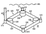
以下、図5a、図5b、図5c、及び図5dにおいて、海洋基礎を設置するための例示的な一実施形態を記載する。図5aは、水面WS下で海底SFに配置されているテンプレート500を概略的に示している。説明のために、テンプレート500は、上記で図1a〜図1cに関して記載したテンプレート100に対応するものとする。しかしながら、このことは本発明にいかなる限定も与えず、上述の別の実施形態に係るテンプレートを代わりに用いてもよい。
In the following, an exemplary embodiment for installing a marine foundation is described in FIGS. 5a, 5b, 5c and 5d. Fig. 5a schematically shows a
テンプレート500は、フレーム体520に結合された中空のガイド部材510と、中空のガイド部材510に対置されたサクションバケット530とを備える。フレーム体520は、中空のガイド部材510及びサクションバケット530が結合されたフレーム部材522によって形成される。
The
テンプレート500は、ポンプシステム550に接続されるが、これは図5aではホース552によって概略的に示されている。ホース552のそれぞれは、サクションバケット530をポンプシステム550に接続する。
The
固定と、必要であれば上述の水平化操作とを行った後、パイルはテンプレートにしたがって海底に設置される。図5bは、第1のパイルP1が海底SFに設置され、矢印A3で示す方向に沿って第2のパイルP2を中空のガイド部材510に挿入することにより、パイルP2が中空のガイド部材510に取り付けられる段階でのパイルの設置を示している。
After fixing and, if necessary, the leveling operation described above, the pile is placed on the seabed according to the template. In FIG. 5b, the pile P2 is inserted into the
図5cは、パイルP1、P2、P3、P4が海底SFに設置され、テンプレートが除去された後の段階でのジャケット式基礎の設置を示している。図示のように、ジャケット式基礎560は、矢印A4、A5で示すようにジャケット式基礎をパイルP1、P2、P3、P4と結合することによって設置される。ジャケット式基礎560は、それぞれのパイルP1、P2、P3、P4に係合するスリーブ部材561、562、563、564を有する。したがって、スリーブ部材561、562、563、564をそれぞれのパイルP1、P2、P3、P4と結合することで、図5dに示すようにジャケット式基礎が海底SFに確実に固定される。
FIG. 5 c shows the installation of the jacketed foundation at a stage after the
いくつかの例示的な例において、ジャケット式基礎560は、洋上風力発電プラントの基礎に相当することができる。
In some illustrative examples, the
通常、より大型のタービン及びより深い水域では、重力着底式基礎又はモノポール式基礎よりもジャケット式基礎が好ましい。本発明は、ジャケット式基礎を改善するのに特によく適している。ジャケット式基礎は、通常は3つ又は4つの脚部を備えるので、したがって3つ又は4つのパイルを必要とする。 Usually, jacketed foundations are preferred over gravity-based foundations or monopole foundations for larger turbines and deeper water areas. The invention is particularly well suited for improving jacketed foundations. A jacketed foundation usually comprises three or four legs and thus requires three or four piles.
ジャケットをパイルに据え付ける場合、所望の精度を得るために穏やかな天候が必要とされる。いくつかの従来技術の方法と同じやり方では、例えばパイルのガイドを水上から制御するので、パイルを海底に挿入するのにも穏やかな天候を必要とした。本発明では、プロセスは専ら水面下で行われるので、おおよそどのような天候でもパイルを配置することが可能である。これは、基礎へのジャケットの据付けにしか穏やかな天候が必要とされないので、複数の基礎を従来よりも少ない時間でセットすることができるという点で、従来技術に優る大きい利点をもたらす。更に、テンプレートを海底に配置することが可能であることにより、パイル間の個々の正確な距離を得ることが、ガイド部材を水面に有するのに比較して容易になることが明らかである。 When installing the jacket on a pile, mild weather is required to obtain the desired accuracy. In the same way as some prior art methods, for example, controlling the guides of the piles from the water required mild weather to insert the piles into the seabed. In the present invention, the process is exclusively under water, so it is possible to place the pile in almost any weather. This provides a significant advantage over the prior art in that multiple foundations can be set in less time than in the prior art as mild weather is only required to install the jacket on the foundation. Furthermore, it is clear that the ability to place the template on the seabed makes it easier to obtain the individual exact distances between the piles compared to having the guide members on the water surface.
海底へのパイルの打込みは、通常はパイルの約1mのみが海底を超えるように行われる。例えば、パイルは、中空のガイド部材の上面とおおよそ同一平面となるように下へ打ち込むことができる。ジャケットの高さが大きく、例えば100mである場合、それによりmmスケールのほんの僅かな位置ずれでさえも比較的大きい程度の傾斜を引き起こす可能性があることを主な理由として、かなりの精度が望まれる。したがって、パイルが海底に挿入された後、厳密な上面高さが測定され、必要であれば、パイルに据え付ける前のジャケットの個々の脚部に更なるリングが付加される。正確な位置決めが得られると、パイルは、ジャケットの脚部とともにグラウトで固められる。 The driving of the pile into the seabed is usually performed so that only about 1 m of the pile exceeds the seabed. For example, the pile can be driven down to be approximately flush with the upper surface of the hollow guide member. If the height of the jacket is large, for example 100 m, considerable accuracy is desired, mainly because it can cause a relatively large degree of tilt even with a slight misalignment of the mm scale. It is. Thus, after the pile is inserted into the seabed, the exact top height is measured and, if necessary, additional rings are added to the individual legs of the jacket before installation on the pile. Once accurate positioning is obtained, the pile is grouted together with the legs of the jacket.
要約すると、洋上基礎を設置する方法及び洋上基礎を設置するのに用いるテンプレートが提供される。例示的な実施形態において、テンプレートは海底に解放可能に固定され、テンプレートはパイルを設置する前に水平にされる。本発明のいくつかの例示的な実施形態に係る方法において、パイルを受ける少なくとも1つの中空のガイド部材と、少なくとも1つのサクションバケットと、少なくとも1つの中空のガイド部材及び少なくとも1つのサクションバケットに結合するフレーム体と、少なくとも1つのサクションバケットに圧力を与えるように構成されている制御手段とを備えるテンプレートを準備することができる。本方法は、テンプレートを海底に配置することと、少なくとも1つのサクションバケットに負圧を与えてサクションバケットを海底に打ち込むことと、少なくとも1つのサクションバケットに与えられる負圧を制御して、フレームを海底に対して水平にするように少なくとも1つのサクションバケットの根入れ深さを調整することとを含むことができる。 In summary, a method of installing an offshore foundation and a template used to install the offshore foundation are provided. In an exemplary embodiment, the template is releasably secured to the sea floor and the template is leveled prior to installing the pile. In a method according to some exemplary embodiments of the invention, coupled to at least one hollow guide member for receiving a pile, at least one suction bucket, at least one hollow guide member and at least one suction bucket. A template can be provided comprising a frame body to be controlled and control means configured to apply pressure to at least one suction bucket. The method includes placing a template on the seabed, applying negative pressure to at least one suction bucket and driving the suction bucket into the seabed, and controlling the negative pressure applied to the at least one suction bucket to Adjusting the depth of penetration of the at least one suction bucket to be level with respect to the seabed.
上述の方法は、洋上風力タービンの複数の基礎を設置するのに特に有用である。洋上風力タービンは、必要とされる陸上へのケーブルを最大限活用するために、最も多くは少なくとも10基のタービンの敷地にもたらされる。本発明では、1つのテンプレートをタービンの複数の基礎を設置するのに用いることができる。更なる実施形態において、テンプレートは、外的な補助/制御なしに、単独で水面下を動き回り、複数のパイル打ち基礎を構成するように、モーター、プロペラ、及びGPSシステムを備えることができる。そのような実施形態において、複数のプロペラ及び/又は多回転プロペラは、海面下を三次元において操縦することが可能である必要がある。いくつかの実施形態では、テンプレートの移動は遠隔で制御することができ、他の実施形態では、この移動は設定されたプログラムによって行うことができ、それによりテンプレートは、いくぶん自律的に移動する。 The method described above is particularly useful for installing multiple foundations for offshore wind turbines. Offshore wind turbines are most often brought to the site of at least 10 turbines in order to make the most of the required onshore cables. In the present invention, a single template can be used to install multiple turbine foundations. In a further embodiment, the template may comprise a motor, propeller, and GPS system to move around under the water alone and form a plurality of pile foundations without external assistance / control. In such embodiments, multiple propellers and / or multi-rotating propellers need to be able to maneuver below sea level in three dimensions. In some embodiments, the movement of the template can be controlled remotely, and in other embodiments, this movement can be performed by a configured program, whereby the template moves somewhat autonomously.
本明細書において使用される「パイル」という用語は、当業者には理解されるように、基礎に対して有用な任意の細長い直立部材を意味することが意図されている。一般的な既製のパイルは、杭打ち機を用いて又は吸引によって海底に打ち込まれる。 The term "pile" as used herein is intended to mean any elongated upright member useful against a foundation, as understood by a person skilled in the art. Typical ready-made piles are driven into the seabed with a piling machine or by suction.
Claims (35)
パイル(P1、P2、P3、P4)を受けるように構成されている少なくとも1つの中空のガイド部材(110)と、少なくとも1つのサクションバケット(130)と、前記少なくとも1つの中空のガイド部材及び前記少なくとも1つのサクションバケットに結合するフレーム体(120)とを備えるテンプレート(100)を準備することと、
前記テンプレートを海底(SF)に配置することと、
該サクションバケットを海底に打ち込むことにより前記テンプレートを海底に解放可能に固定するために、前記少なくとも1つのサクションバケットに負圧を与えることと、
前記フレーム体を海底に対して水平にするように前記少なくとも1つのサクションバケットの根入れ深さを調整するため、前記少なくとも1つのサクションバケットに与えられる前記負圧を制御することと、
前記少なくとも1つのパイルを前記中空のガイド部材内に配置することと、
前記中空のガイド部材によってガイドされる前記少なくとも1つのパイルを海底に打ち込むことと、
を含む、方法。 A method of installing a foundation for an offshore wind turbine, the method comprising:
At least one hollow guide member (110) configured to receive a pile (P1, P2, P3, P4), at least one suction bucket (130), said at least one hollow guide member and said Providing a template (100) comprising a frame body (120) coupled to at least one suction bucket;
Placing the template on the seabed (SF);
Applying negative pressure to the at least one suction bucket to releasably secure the template to the seabed by driving the suction bucket into the seabed;
Controlling the negative pressure applied to the at least one suction bucket to adjust the penetration depth of the at least one suction bucket so as to make the frame body horizontal with respect to the seabed;
Disposing the at least one pile in the hollow guide member;
Driving the at least one pile guided by the hollow guide member into the seabed;
Method, including.
パイル(P1、P2、P3、P4)を受ける少なくとも1つの中空のガイド部材(110)と、
少なくとも1つのサクションバケット(130)と、
前記少なくとも1つの中空のガイド部材と前記少なくとも1つのサクションバケットとを結合するフレーム体(120)と、
前記少なくとも1つのサクションバケットに圧力を与えるように構成されている制御手段と、を備え、
前記テンプレートは海底に解放可能に固定される、テンプレート。 A template (100) used to install the foundation of an offshore wind turbine,
At least one hollow guide member (110) for receiving piles (P1, P2, P3, P4);
At least one suction bucket (130),
A frame body (120) coupling the at least one hollow guide member and the at least one suction bucket;
Control means configured to apply pressure to the at least one suction bucket;
The template Ru is releasably secured to the seabed, the template.
Applications Claiming Priority (3)
| Application Number | Priority Date | Filing Date | Title |
|---|---|---|---|
| DKPA201370470 | 2013-08-28 | ||
| DKPA201370470 | 2013-08-28 | ||
| PCT/DK2014/000043 WO2015028020A1 (en) | 2013-08-28 | 2014-08-28 | Method of installing a foundation for an offshore wind turbine and a template for use herein |
Publications (2)
| Publication Number | Publication Date |
|---|---|
| JP2016529426A JP2016529426A (en) | 2016-09-23 |
| JP6554101B2 true JP6554101B2 (en) | 2019-07-31 |
Family
ID=51421787
Family Applications (1)
| Application Number | Title | Priority Date | Filing Date |
|---|---|---|---|
| JP2016537137A Active JP6554101B2 (en) | 2013-08-28 | 2014-08-28 | Method of laying foundations of offshore wind turbines and template used for laying foundations of offshore wind turbines |
Country Status (7)
| Country | Link |
|---|---|
| US (1) | US10100482B2 (en) |
| EP (1) | EP3039192B1 (en) |
| JP (1) | JP6554101B2 (en) |
| KR (1) | KR101737931B1 (en) |
| CN (1) | CN105473791B (en) |
| DK (1) | DK3039192T3 (en) |
| WO (1) | WO2015028020A1 (en) |
Families Citing this family (28)
| Publication number | Priority date | Publication date | Assignee | Title |
|---|---|---|---|---|
| NO342443B1 (en) | 2015-11-25 | 2018-05-22 | Neodrill As | Well head foundations system |
| CN105332387B (en) * | 2015-11-25 | 2018-06-12 | 国网浙江省电力公司 | A kind of large size transmission tower Blade fence structure and construction method |
| GB2549458A (en) * | 2016-04-11 | 2017-10-25 | Statoil Petroleum As | Subsea foundation |
| CN105926664B (en) * | 2016-05-11 | 2018-04-03 | 中国海洋大学 | Suitable for passing through negative pressure cylinder and installation method to sea bottom surface under oceanic winds electric energy |
| CN105926666B (en) * | 2016-05-11 | 2018-03-13 | 中国海洋大学 | The suction anchor of soil plug can be eliminated automatically |
| CN105926661B (en) * | 2016-05-11 | 2018-03-13 | 中国海洋大学 | The negative pressure cylinder base of the offshore wind farm of soil plug can be eliminated |
| CN105926627B (en) * | 2016-05-11 | 2018-04-03 | 中国海洋大学 | The suction anchor and its installation method that can be passed through to sea bottom surface down |
| CN106872211B (en) * | 2017-03-31 | 2023-12-15 | 派格水下技术(广州)有限公司 | Coring system based on remote control submersible |
| CN106930261B (en) * | 2017-04-19 | 2023-10-27 | 合肥学院 | Simple ocean platform in intertidal zone and construction method thereof |
| JP6902190B2 (en) * | 2017-05-22 | 2021-07-14 | 株式会社大林組 | Intrusive foundation penetration method and penetration management device |
| NL2019068B1 (en) * | 2017-06-14 | 2018-12-21 | Ihc Holland Ie Bv | A template and a method of using the template |
| US10438730B2 (en) * | 2017-10-31 | 2019-10-08 | Cyntec Co., Ltd. | Current sensing resistor and fabrication method thereof |
| ES2725877B2 (en) * | 2018-03-27 | 2020-02-10 | Ingecid Investig Y Desarrollo De Proyectos S L | Procedure of construction of a concrete foundation for offshore structures type lattice, and foundation built with this procedure. |
| PL3584371T3 (en) * | 2018-06-18 | 2022-12-19 | Vallourec Deutschland Gmbh | Device for verifying the bearing capacity of a pile of an offshore foundation construction |
| WO2020005173A1 (en) * | 2018-06-26 | 2020-01-02 | Sa-Ra Enerji Insaat Ticaret Ve Sanayi Anonim Sirketi | Connection apparatus for mounting a guyed mast. |
| CN210031889U (en) * | 2018-12-14 | 2020-02-07 | 上海勘测设计研究院有限公司 | Offshore wind turbine single pile-suction barrel combined foundation |
| TWI691646B (en) * | 2018-12-20 | 2020-04-21 | 財團法人船舶暨海洋產業研發中心 | Common undertaking platform for underwater base assembly and transportation |
| NL2022553B1 (en) | 2019-02-11 | 2020-08-19 | Temporary Works Design Eng B V | Pile installation template |
| CN110468840A (en) * | 2019-09-16 | 2019-11-19 | 江苏亨通蓝德海洋工程有限公司 | A kind of negative pressure barrel type single pile pile gripper construction mechanism and its construction method |
| CN112983748B (en) * | 2019-12-13 | 2022-06-14 | 中国电建集团华东勘测设计研究院有限公司 | Integrally-installed offshore electrical platform and manufacturing and installing method thereof |
| KR102348552B1 (en) * | 2020-06-29 | 2022-01-07 | 한국전력공사 | Bucket of marine wind power generation apparatus and marine wind power generation apparatus including the same, and installation method of marine wind power generation apparatus |
| CN112523252B (en) * | 2020-11-18 | 2021-09-07 | 河海大学 | Recyclable seabed anti-sinking plate suitable for uneven seabed and installation and use method |
| KR102398858B1 (en) * | 2020-12-28 | 2022-05-17 | 이태환 | Apparatus for real-time monitoring and remote control of installation work of off-shore structures supported with suction bucket foundations |
| CN113389226B (en) * | 2021-06-01 | 2023-02-28 | 天津港航工程有限公司 | Construction method for offshore wind power foundation anti-scouring structure |
| TW202323144A (en) * | 2021-06-10 | 2023-06-16 | 美商特拉通系統股份有限公司 | Group anchor system, subsea installation system, method for using and installing same |
| KR102443891B1 (en) * | 2021-10-18 | 2022-09-16 | (주)대한엔지니어링 | Jig assembly for interpenetration of marine monopile and the interpenetration method using this |
| KR102465355B1 (en) * | 2021-11-05 | 2022-11-10 | (주)대한엔지니어링 | Jig assembly for interpenetration of marine suction pile and the interpenetration method using this |
| KR102692391B1 (en) | 2022-06-24 | 2024-08-05 | 한국해양과학기술원 | Modular pre-piling underwater template with independent leg structure |
Family Cites Families (23)
| Publication number | Priority date | Publication date | Assignee | Title |
|---|---|---|---|---|
| JPS6149029A (en) | 1984-08-13 | 1986-03-10 | Nippon Steel Corp | Underwater foundation fixer |
| SE445473B (en) * | 1984-11-09 | 1986-06-23 | Offshore Ab J & W | FUNDAMENTAL ELEMENTS OF BUSINESS PROVIDED FOR UNDERWATER USE AND APPLICATION OF THIS |
| US5899639A (en) * | 1996-02-22 | 1999-05-04 | Mcdermott International, Inc. | Offshore structure for extreme water depth |
| JP3603193B2 (en) | 1997-11-28 | 2004-12-22 | 株式会社大林組 | How to build an underwater foundation |
| NZ507939A (en) * | 1998-04-02 | 2002-08-28 | Suction Pile Technology B | Marine structure with suction piles for embedment into the sub-sea bottom |
| DE202004021468U1 (en) * | 2004-09-08 | 2008-05-08 | Maierform Maritime Technology Gmbh | Device for transport and erection of a wind turbine |
| CN200971492Y (en) | 2005-11-07 | 2007-11-07 | 天津市海王星海上工程技术有限公司 | Pile submarine drilling basal disc with suction |
| EP2010718B1 (en) | 2006-04-10 | 2019-08-07 | MBD Offshore Power A/S | Method of installing bucket foundation structure |
| WO2008052556A2 (en) * | 2006-11-03 | 2008-05-08 | Vestas Wind Systems A/S | A wind energy converter, a wind turbine foundation, a method and use of a wind turbine foundation |
| GB0905663D0 (en) * | 2009-04-01 | 2009-05-13 | Marine Current Turbines Ltd | Methods of and apparatus for the installation of columns/piles |
| JP5278828B2 (en) | 2010-01-13 | 2013-09-04 | Jfeエンジニアリング株式会社 | How to install the jacket |
| PL2354321T3 (en) | 2010-01-13 | 2013-05-31 | Geosea Nv | Method of providing a foundation for an elevated mass, and assembly of a jack-up platform and a framed template for carrying out the method. |
| CN101768978B (en) * | 2010-01-29 | 2012-04-25 | 江苏道达海上风电工程科技有限公司 | At-sea wind generation unit foundation formed by barrel type foundation and mooring rope anchor |
| DK2402511T3 (en) * | 2010-07-02 | 2016-06-06 | Ihc Holland Ie Bv | Template for and method of installation of a plurality of foundation members in an underwater land formation. |
| CN201779093U (en) | 2010-07-14 | 2011-03-30 | 中国海洋石油总公司 | Pump skid for installation of deepwater suction bucket foundation |
| CN102561285A (en) | 2010-12-20 | 2012-07-11 | 三一电气有限责任公司 | Suction penetration control method |
| KR101048023B1 (en) * | 2011-02-09 | 2011-07-13 | 이종석 | System pile unit of type suction |
| KR101044753B1 (en) * | 2011-04-04 | 2011-06-27 | (주)대우건설 | Apparatus for correcting inclination of offshore wind power generation facility using internal compartment |
| BE1020071A5 (en) * | 2011-07-11 | 2013-04-02 | Geosea N V | METHOD FOR PROVIDING A FOUNDATION FOR A MASS FIXED AT HEIGHT AND A POSITIONING FRAME FOR CARRYING OUT THE METHOD. |
| CN202176267U (en) | 2011-08-19 | 2012-03-28 | 天津市海王星海上工程技术有限公司 | Novel suction pile type seabed drilling base plate |
| CN202273241U (en) * | 2011-10-26 | 2012-06-13 | 浙江大学 | Suction bucket- pile composite type base |
| NL2008279C2 (en) * | 2012-02-13 | 2013-08-14 | Ihc Holland Ie Bv | A template for and method of installing a plurality of foundation elements in an underwater ground formation. |
| NO336982B1 (en) * | 2012-12-19 | 2015-12-07 | Sevan Marine Asa | Submersible hull with levelable foundation and method of supporting the hull on a seabed |
-
2014
- 2014-08-28 JP JP2016537137A patent/JP6554101B2/en active Active
- 2014-08-28 EP EP14755984.3A patent/EP3039192B1/en active Active
- 2014-08-28 US US14/915,317 patent/US10100482B2/en active Active
- 2014-08-28 WO PCT/DK2014/000043 patent/WO2015028020A1/en active Application Filing
- 2014-08-28 KR KR1020167008086A patent/KR101737931B1/en active IP Right Grant
- 2014-08-28 CN CN201480046061.XA patent/CN105473791B/en active Active
- 2014-08-28 DK DK14755984.3T patent/DK3039192T3/en active
Also Published As
| Publication number | Publication date |
|---|---|
| WO2015028020A1 (en) | 2015-03-05 |
| US20160208453A1 (en) | 2016-07-21 |
| KR101737931B1 (en) | 2017-05-19 |
| JP2016529426A (en) | 2016-09-23 |
| US10100482B2 (en) | 2018-10-16 |
| EP3039192B1 (en) | 2017-10-11 |
| EP3039192A1 (en) | 2016-07-06 |
| CN105473791A (en) | 2016-04-06 |
| CN105473791B (en) | 2017-03-15 |
| DK3039192T3 (en) | 2017-11-20 |
| KR20160045148A (en) | 2016-04-26 |
Similar Documents
| Publication | Publication Date | Title |
|---|---|---|
| JP6554101B2 (en) | Method of laying foundations of offshore wind turbines and template used for laying foundations of offshore wind turbines | |
| JP5774158B2 (en) | Installation of submerged support structure | |
| EP2492401B1 (en) | Device for manufacturing a foundation for a mass located at height, associated method and assembly of the device and a jack-up platform | |
| EP2546418B1 (en) | Method for providing a foundation for a mass located at height | |
| US20150125220A1 (en) | Offshore structure installation | |
| JP5278828B2 (en) | How to install the jacket | |
| AU2011200123A1 (en) | Method of Providing a Foundation for an Elevated Mass, and Assembly of a Jacked-Up Platform and a Framed Template for Carrying Out the Method | |
| EP2851472B1 (en) | Positioning framework | |
| EP2913439B1 (en) | Device and method for arranging foundation piles in an underwater bottom | |
| JP6792240B2 (en) | Scuttling prevention device for steel pipe piles, scuttling prevention structure and scuttling prevention method | |
| KR102185234B1 (en) | Pre-piling template using spudcan and installation method of offshore structure using thereof | |
| CN109707002B (en) | Device and method for accurately positioning, sinking and installing large water intake head | |
| TWI826763B (en) | Method for providing a load structure, support for supporting a load structure and installing method thereof and pile and jacket for use in the installing method, and pile guiding frame for installing a support | |
| JP2004285735A (en) | Method of constructing temporary landing bridge by using truss frame | |
| KR101205576B1 (en) | Pile Construction Apparatus to support Horizontal Stability on Irregular Sea-Bed | |
| CN110080274A (en) | A kind of offshore wind farm cushion cap foundation construction method | |
| CN109469080B (en) | Underwater rock-socketed steel sheet pile cofferdam structure and construction method thereof | |
| KR102692391B1 (en) | Modular pre-piling underwater template with independent leg structure | |
| KR102557752B1 (en) | Pre-drilling and positioning method for installation of jacket foundation | |
| JP2018104893A (en) | Construction method for discharge channel and support structure of pipe body with curve in water | |
| CN118166667A (en) | Bracket erecting method | |
| JPH1018298A (en) | Caisson settling method |
Legal Events
| Date | Code | Title | Description |
|---|---|---|---|
| A621 | Written request for application examination |
Free format text: JAPANESE INTERMEDIATE CODE: A621 Effective date: 20170818 |
|
| A977 | Report on retrieval |
Free format text: JAPANESE INTERMEDIATE CODE: A971007 Effective date: 20180720 |
|
| A131 | Notification of reasons for refusal |
Free format text: JAPANESE INTERMEDIATE CODE: A131 Effective date: 20180726 |
|
| A521 | Request for written amendment filed |
Free format text: JAPANESE INTERMEDIATE CODE: A523 Effective date: 20181023 |
|
| A131 | Notification of reasons for refusal |
Free format text: JAPANESE INTERMEDIATE CODE: A131 Effective date: 20190108 |
|
| A521 | Request for written amendment filed |
Free format text: JAPANESE INTERMEDIATE CODE: A523 Effective date: 20190408 |
|
| TRDD | Decision of grant or rejection written | ||
| A01 | Written decision to grant a patent or to grant a registration (utility model) |
Free format text: JAPANESE INTERMEDIATE CODE: A01 Effective date: 20190606 |
|
| A61 | First payment of annual fees (during grant procedure) |
Free format text: JAPANESE INTERMEDIATE CODE: A61 Effective date: 20190705 |
|
| R150 | Certificate of patent or registration of utility model |
Ref document number: 6554101 Country of ref document: JP Free format text: JAPANESE INTERMEDIATE CODE: R150 |
|
| S531 | Written request for registration of change of domicile |
Free format text: JAPANESE INTERMEDIATE CODE: R313531 |
|
| S533 | Written request for registration of change of name |
Free format text: JAPANESE INTERMEDIATE CODE: R313533 |
|
| R350 | Written notification of registration of transfer |
Free format text: JAPANESE INTERMEDIATE CODE: R350 |
|
| R250 | Receipt of annual fees |
Free format text: JAPANESE INTERMEDIATE CODE: R250 |
|
| S111 | Request for change of ownership or part of ownership |
Free format text: JAPANESE INTERMEDIATE CODE: R313113 |
|
| R350 | Written notification of registration of transfer |
Free format text: JAPANESE INTERMEDIATE CODE: R350 |
|
| R250 | Receipt of annual fees |
Free format text: JAPANESE INTERMEDIATE CODE: R250 |
|
| R250 | Receipt of annual fees |
Free format text: JAPANESE INTERMEDIATE CODE: R250 |