JP6550805B2 - Game machine - Google Patents
Game machine Download PDFInfo
- Publication number
- JP6550805B2 JP6550805B2 JP2015051514A JP2015051514A JP6550805B2 JP 6550805 B2 JP6550805 B2 JP 6550805B2 JP 2015051514 A JP2015051514 A JP 2015051514A JP 2015051514 A JP2015051514 A JP 2015051514A JP 6550805 B2 JP6550805 B2 JP 6550805B2
- Authority
- JP
- Japan
- Prior art keywords
- displacement member
- driven member
- display
- ball
- case body
- Prior art date
- Legal status (The legal status is an assumption and is not a legal conclusion. Google has not performed a legal analysis and makes no representation as to the accuracy of the status listed.)
- Active
Links
Images


Landscapes
- Display Devices Of Pinball Game Machines (AREA)
Description
本発明は、パチンコ機などの遊技機に関するものである。 The present invention relates to a gaming machine such as a pachinko machine.
従来より、1つの液晶表示装置等の表示装置を設け、表示装置にて様々な演出画像を表示する遊技機が提案されている。 BACKGROUND Conventionally, a gaming machine has been proposed in which a display device such as a liquid crystal display device is provided, and various effect images are displayed on the display device.
この種のパチンコ機において、様々な演出画像を表示することは可能であるが、演出画像が表示される箇所が1箇所のみであるため、演出画像を用いた意外性のある遊技を提供することが出来ず、遊技者が飽きてしまうという問題点があった。 In this type of pachinko machine, it is possible to display various effect images, but since there is only one place where the effect image is displayed, providing a surprising game using the effect image There is a problem that the player can get bored.
本発明は、上記例示した問題点等を解決するためになされたものであり、遊技者の飽きを緩和させることができる遊技機を提供することを目的とする。 The present invention has been made to solve the above illustrated problem like, and an object thereof is to provide a gaming machine which can mitigate the bored in Yu technique's.
この目的を達成するために本発明の遊技機は、第1表示領域を有した第1表示手段と、取得条件の成立に基づいて、情報を取得可能な取得手段と、前記取得手段により取得された前記情報が複数記憶されることが可能な記憶手段と、その記憶手段に記憶された前記情報に基づいて判別を実行することが可能な判別手段と、その判別手段による判別結果を示すための演出として前記第1表示手段に第1演出を実行可能な第1演出実行手段と、を有し、前記第1表示領域とは異なる第2表示領域を有した第2表示手段と、前記記憶手段に記憶されている前記判別手段により前記判別が実行される前の前記情報に基づいて判別を実行する事前判別手段と、その事前判別手段による事前判別結果を示すための演出として前記第2表示手段に第2演出を実行可能な第2演出実行手段と、前記記憶手段に記憶されている複数の前記情報から、任意の情報を選択する情報選択手段と、を有し、前記第2表示手段は、前記記憶手段に記憶されている複数の前記情報のそれぞれに対応した前記第2演出が表示されることが可能に構成されており、前記遊技機は、所定の条件が成立したことに基づいて、前記第1表示手段に表示されている前記第1演出を前記第2表示手段に移動させて表示させ、前記第2表示手段に表示されている前記情報選択手段により選択された前記情報に対応した前記第2演出を前記第1表示手段に移動させて表示させることが可能な手段を有するものである。 Gaming machine of the present invention in order to achieve the object, obtains a first display means having a first display area, based on the establishment of acquisition conditions, an acquisition unit capable of acquiring information, by the acquisition unit A storage means capable of storing a plurality of the information, a determination means capable of executing a determination based on the information stored in the storage means, and a determination result by the determination means A first effect executing means capable of executing the first effect on the first display means, and a second display means having a second display area different from the first display area, and the storage Pre-discrimination means for executing discrimination based on the information before the discrimination is performed by the discrimination means stored in the means, and the second display as an effect for showing the pre-discrimination result by the prior discrimination means The second effect on the means And row second possible effect execution means, from a plurality of said information stored in said storage means includes a data selecting means for selecting an arbitrary information, and the second display means, in the storage means The second effect corresponding to each of the plurality of stored information can be displayed, and the gaming machine can display the first display based on a predetermined condition being satisfied. The first effect displayed on the means is moved and displayed on the second display means, and the second effect corresponding to the information selected by the information selection means displayed on the second display means Is moved to the first display means and can be displayed .
本発明の遊技機によれば、第1表示領域を有した第1表示手段と、取得条件の成立に基づいて、情報を取得可能な取得手段と、前記取得手段により取得された前記情報が複数記憶されることが可能な記憶手段と、その記憶手段に記憶された前記情報に基づいて判別を実行することが可能な判別手段と、その判別手段による判別結果を示すための演出として前記第1表示手段に第1演出を実行可能な第1演出実行手段と、を有し、前記第1表示領域とは異なる第2表示領域を有した第2表示手段と、前記記憶手段に記憶されている前記判別手段により前記判別が実行される前の前記情報に基づいて判別を実行する事前判別手段と、その事前判別手段による事前判別結果を示すための演出として前記第2表示手段に第2演出を実行可能な第2演出実行手段と、前記記憶手段に記憶されている複数の前記情報から、任意の情報を選択する情報選択手段と、を有し、前記第2表示手段は、前記記憶手段に記憶されている複数の前記情報のそれぞれに対応した前記第2演出が表示されることが可能に構成されており、前記遊技機は、所定の条件が成立したことに基づいて、前記第1表示手段に表示されている前記第1演出を前記第2表示手段に移動させて表示させ、前記第2表示手段に表示されている前記情報選択手段により選択された前記情報に対応した前記第2演出を前記第1表示手段に移動させて表示させることが可能な手段を有するものであるため、遊技者の飽きを緩和させることができるという効果がある。 According to the gaming machine of the present invention, a first display unit having a first display area, based on the establishment of acquisition conditions, an acquisition unit capable of acquiring information, the information obtained by the obtaining means A plurality of storage means capable of being stored, a determination means capable of executing determination based on the information stored in the storage means, and an effect for indicating a determination result by the determination means First display executing means capable of executing a first effect on one display means, second display means having a second display area different from the first display area, and stored in the storage means A pre-discriminating unit for performing discrimination based on the information before the discrimination is performed by the discriminating unit, and a second effect on the second display unit as an effect for indicating the pre-discrimination result by the prior discriminating unit. The second production that can be performed And line unit, a plurality of said information stored in said storage means includes a data selecting means for selecting an arbitrary information, and the second display means, the plurality stored in said storage means The second effect corresponding to each of the information can be displayed, and the gaming machine is displayed on the first display means based on a predetermined condition being satisfied. The first effect is moved to the second display means for display, and the second effect corresponding to the information selected by the information selection means displayed on the second display means is displayed on the first display means. since the display is moved and has a means capable, there is an effect that it is possible to relax the tired of Yu technique's.
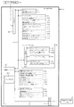
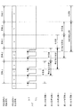
以下、本発明の実施形態について、添付図面を参照して説明する。まず、図1から図39を参照し、第1実施形態として、本発明をパチンコ遊技機(以下、単に「パチンコ機」という)10に適用した場合の一実施形態について説明する。図1は、第1実施形態におけるパチンコ機10の正面図であり、図2はパチンコ機10の遊技盤13の正面図であり、図3はパチンコ機10の背面図である。
Embodiments of the present invention will be described below with reference to the accompanying drawings. First, with reference to FIGS. 1 to 39, as a first embodiment, an embodiment in which the present invention is applied to a pachinko gaming machine (hereinafter simply referred to as “pachinko machine”) 10 will be described. 1 is a front view of a
図1に示すように、パチンコ機10は、略矩形状に組み合わせた木枠により外殻が形成される外枠11と、その外枠11と略同一の外形形状に形成され外枠11に対して開閉可能に支持された内枠12とを備えている。外枠11には、内枠12を支持するために正面視(図1参照)左側の上下2カ所に金属製のヒンジ18が取り付けられ、そのヒンジ18が設けられた側を開閉の軸として内枠12が正面手前側へ開閉可能に支持されている。
As shown in FIG. 1, the
内枠12には、多数の釘や入賞口63,64等を有する遊技盤13(図2参照)が裏面側から着脱可能に装着される。この遊技盤13の前面を球(遊技球)が流下することにより弾球遊技が行われる。なお、内枠12には、球を遊技盤13の前面領域に発射する球発射ユニット112a(図4参照)やその球発射ユニット112aから発射された球を遊技盤13の前面領域まで誘導する発射レール(図示せず)等が取り付けられている。
A game board 13 (see FIG. 2) having a large number of nails, winning
内枠12の前面側には、その前面上側を覆う前面枠14と、その下側を覆う下皿ユニット15とが設けられている。前面枠14及び下皿ユニット15を支持するために正面視(図1参照)左側の上下2カ所に金属製のヒンジ19が取り付けられ、そのヒンジ19が設けられた側を開閉の軸として前面枠14及び下皿ユニット15が正面手前側へ開閉可能に支持されている。なお、内枠12の施錠と前面枠14の施錠とは、シリンダ錠20の鍵穴21に専用の鍵を差し込んで所定の操作を行うことでそれぞれ解除される。
On the front side of the
前面枠14は、装飾用の樹脂部品や電気部品等を組み付けたものであり、その略中央部には略楕円形状に開口形成された窓部14cが設けられている。前面枠14の裏面側には2枚の板ガラスを有するガラスユニット16が配設され、そのガラスユニット16を介して遊技盤13の前面がパチンコ機10の正面側に視認可能となっている。
The
前面枠14には、球を貯留する上皿17が前方へ張り出して上面を開放した略箱状に形成されており、この上皿17に賞球や貸出球などが排出される。上皿17の底面は正面視(図1参照)右側に下降傾斜して形成され、その傾斜により上皿17に投入された球が球発射ユニット112a(図4参照)へと案内される。また、上皿17の上面には、枠ボタン22が設けられている。この枠ボタン22は、例えば、第3図柄表示装置81(図2参照)で表示される演出のステージを変更したり、スーパーリーチの演出内容を変更したりする場合などに、遊技者により操作される。
In the
前面枠14には、その周囲(例えばコーナー部分)に各種ランプ等の発光手段が設けられている。これら発光手段は、大当たり時や所定のリーチ時等における遊技状態の変化に応じて、点灯又は点滅することにより発光態様が変更制御され、遊技中の演出効果を高める役割を果たす。窓部14cの周縁には、LED等の発光手段を内蔵した電飾部29〜33が設けられている。パチンコ機10においては、これら電飾部29〜33が大当たりランプ等の演出ランプとして機能し、大当たり時やリーチ演出時等には内蔵するLEDの点灯や点滅によって各電飾部29〜33が点灯または点滅して、大当たり中である旨、或いは大当たり一歩手前のリーチ中である旨が報知される。また、前面枠14の正面視(図1参照)左上部には、LED等の発光手段が内蔵され賞球の払い出し中とエラー発生時とを表示可能な表示ランプ34が設けられている。
The
また、右側の電飾部32下側には、前面枠14の裏面側を視認できるように裏面側より透明樹脂を取り付けて小窓35が形成され、遊技盤13前面の貼着スペースK1(図2参照)に貼付される証紙等がパチンコ機10の前面から視認可能とされている。また、パチンコ機10においては、より煌びやかさを醸し出すために、電飾部29〜33の周りの領域にクロムメッキを施したABS樹脂製のメッキ部材36が取り付けられている。
In addition, a small window 35 is formed by attaching a transparent resin from the back side so that the back side of the
窓部14cの下方には、貸球操作部40が配設されている。貸球操作部40には、度数表示部41と、球貸しボタン42と、返却ボタン43とが設けられている。パチンコ機10の側方に配置されるカードユニット(球貸しユニット)(図示せず)に紙幣やカード等を投入した状態で貸球操作部40が操作されると、その操作に応じて球の貸出が行われる。具体的には、度数表示部41はカード等の残額情報が表示される領域であり、内蔵されたLEDが点灯して残額情報として残額が数字で表示される。球貸しボタン42は、カード等(記録媒体)に記録された情報に基づいて貸出球を得るために操作されるものであり、カード等に残額が存在する限りにおいて貸出球が上皿17に供給される。返却ボタン43は、カードユニットに挿入されたカード等の返却を求める際に操作される。なお、カードユニットを介さずに球貸し装置等から上皿17に球が直接貸し出されるパチンコ機、いわゆる現金機では貸球操作部40が不要となるが、この場合には、貸球操作部40の設置部分に飾りシール等を付加して部品構成は共通のものとしても良い。カードユニットを用いたパチンコ機と現金機との共通化を図ることができる。
A ball
上皿17の下側に位置する下皿ユニット15には、その中央部に上皿17に貯留しきれなかった球を貯留するための下皿50が上面を開放した略箱状に形成されている。下皿50の右側には、球を遊技盤13の前面へ打ち込むために遊技者によって操作される操作ハンドル51が配設される。
In the
操作ハンドル51の内部には、球発射ユニット112aの駆動を許可するためのタッチセンサ51aと、押下操作している期間中には球の発射を停止する発射停止スイッチ51bと、操作ハンドル51の回動操作量(回動位置)を電気抵抗の変化により検出する可変抵抗器(図示せず)などが内蔵されている。操作ハンドル51が遊技者によって右回りに回動操作されると、タッチセンサ51aがオンされると共に可変抵抗器の抵抗値が回動操作量に対応して変化し、その可変抵抗器の抵抗値に対応した強さ(発射強度)で球が発射され、これにより遊技者の操作に対応した飛び量で遊技盤13の前面へ球が打ち込まれる。また、操作ハンドル51が遊技者により操作されていない状態においては、タッチセンサ51aおよび発射停止スイッチ51bがオフとなっている。
Inside the
下皿50の正面下方部には、下皿50に貯留された球を下方へ排出する際に操作するための球抜きレバー52が設けられている。この球抜きレバー52は、常時、右方向に付勢されており、その付勢に抗して左方向へスライドさせることにより、下皿50の底面に形成された底面口が開口して、その底面口から球が自然落下して排出される。この球抜きレバー52の操作は、通常、下皿50の下方に下皿50から排出された球を受け取る箱(一般に「千両箱」と称される)を置いた状態で行われる。下皿50の右方には、上述したように操作ハンドル51が配設され、下皿50の左方には灰皿53が取り付けられている。
In the lower part of the front of the
図2に示すように、遊技盤13は、正面視略正方形状に切削加工したベース板60に、球案内用の多数の釘(図示せず)や風車の他、レール61,62、一般入賞口63、第1入賞口64、第2入賞口640、可変入賞装置65、スルーゲート67、可変表示装置ユニット80等を組み付けて構成され、その周縁部が内枠12(図1参照)の裏面側に取り付けられる。ベース板60は光透過性の樹脂材料からなり、その正面側からベース板60の背面側に配設された各種構造体を遊技者に視認させることが可能に形成される。一般入賞口63、第1入賞口64、第2入賞口640、可変入賞装置65、可変表示装置ユニット80は、ルータ加工によってベース板60に形成された貫通穴に配設され、遊技盤13の前面側からタッピングネジ等により固定されている。
As shown in FIG. 2, the
遊技盤13の前面中央部分は、前面枠14の窓部14c(図1参照)を通じて内枠12の前面側から視認することができる。以下に、主に図2を参照して、遊技盤13の構成について説明する。
The front center portion of the
遊技盤13の前面には、帯状の金属板を略円弧状に屈曲加工して形成した外レール62が植立され、その外レール62の内側位置には外レール62と同様に帯状の金属板で形成した円弧状の内レール61が植立される。この内レール61と外レール62とにより遊技盤13の前面外周が囲まれ、遊技盤13とガラスユニット16(図1参照)とにより前後が囲まれることにより、遊技盤13の前面には、球の挙動により遊技が行われる遊技領域が形成される。遊技領域は、遊技盤13の前面であって2本のレール61,62とレール間を繋ぐ樹脂製の外縁部材73とにより区画して形成される領域(入賞口等が配設され、発射された球が流下する領域)である。
An
2本のレール61,62は、球発射ユニット112a(図4参照)から発射された球を遊技盤13上部へ案内するために設けられたものである。内レール61の先端部分(図2の左上部)には戻り球防止部材68が取り付けられ、一旦、遊技盤13の上部へ案内された球が再度球案内通路内に戻ってしまうといった事態が防止される。外レール62の先端部(図2の右上部)には、球の最大飛翔部分に対応する位置に返しゴム69が取り付けられ、所定以上の勢いで発射された球は、返しゴム69に当たって、勢いが減衰されつつ中央部側へ跳ね返される。
The two
遊技領域の正面視左側下部(図2の左側下部)には、発光手段である複数のLED及び7セグメント表示器を備える第1図柄表示装置37A,37Bが配設されている。第1図柄表示装置37A,37Bは、主制御装置110(図4参照)で行われる各制御に応じた表示がなされるものであり、主にパチンコ機10の遊技状態の表示が行われる。本実施形態では、第1図柄表示装置37A,37Bは、球が、第1入賞口64へ入賞したか、第2入賞口640へ入賞したかに応じて使い分けられるように構成されている。具体的には、球が、第1入賞口64へ入賞した場合には、第1図柄表示装置37Aが作動し、一方で、球が、第2入賞口640へ入賞した場合には、第1図柄表示装置37Bが作動するように構成されている。
First
また、第1図柄表示装置37A,37Bは、LEDにより、パチンコ機10が確変中か時短中か通常中であるかを点灯状態により示したり、変動中であるか否かを点灯状態により示したり、停止図柄が確変大当たりに対応した図柄か普通大当たりに対応した図柄か外れ図柄であるかを点灯状態により示したり、保留球数を点灯状態により示すと共に、7セグメント表示装置により、大当たり中のラウンド数やエラー表示を行う。なお、複数のLEDは、それぞれのLEDの発光色(例えば、赤、緑、青)が異なるよう構成され、その発光色の組み合わせにより、少ないLEDでパチンコ機10の各種遊技状態を示唆することができる。
In addition, the first
尚、本パチンコ機10では、第1入賞口64及び第2入賞口640へ入賞があったことを契機として抽選が行われる。パチンコ機10は、その抽選において、大当たりか否かの当否判定(大当たり抽選)を行うと共に、大当たりと判定した場合はその大当たり種別の判定も行う。ここで判定される大当たり種別としては、15R確変大当たり、4R確変大当たり、15R通常大当たりが用意されている。第1図柄表示装置37A,37Bには、変動終了後の停止図柄として抽選の結果が大当たりであるか否かが示されるだけでなく、大当たりである場合はその大当たり種別に応じた図柄が示される。
In the
ここで、「15R確変大当たり」とは、最大ラウンド数が15ラウンドの大当たりの後に高確率状態へ移行する確変大当たりのことであり、「4R確変大当たり」とは、最大ラウンド数が4ラウンドの大当たりの後に高確率状態へ移行する確変大当たりのことである。また、「15R通常大当たり」は、最大ラウンド数が15ラウンドの大当たりの後に、低確率状態へ移行すると共に、所定の変動回数の間(例えば、100変動回数)は時短状態となる大当たりのことである。 Here, "15R probability variation jackpot" is a probability variation jackpot where the maximum number of rounds shifts to a high probability state after 15 round jackpots, and "4R probability variation jackpot" is a maximum number of round jackpots with 4 rounds It is a probabilistic jackpot that shifts to a high probability state after. In addition, “15R normal jackpot” is a jackpot that shifts to a low probability state after the maximum number of rounds of 15 rounds and hits a short time during a predetermined number of fluctuations (for example, 100 fluctuations). is there.
また、「高確率状態」とは、大当たり終了後に付加価値としてその後の大当たり確率がアップした状態、いわゆる確率変動中(確変中)の時をいい、換言すれば、特別遊技状態へ移行し易い遊技の状態のことである。本実施形態における高確率状態(確変中)は、後述する第2図柄の当たり確率がアップして第2入賞口640へ球が入賞し易い遊技の状態を含む。「低確率状態」とは、確変中でない時をいい、大当たり確率が通常の状態、即ち、確変の時より大当たり確率が低い状態をいう。また、「低確率状態」のうちの時短状態(時短中)とは、大当たり確率が通常の状態であると共に、大当たり確率がそのままで第2図柄の当たり確率のみがアップして第2入賞口640へ球が入賞し易い遊技の状態のことをいう。一方、パチンコ機10が通常中とは、確変中でも時短中でもない遊技の状態(大当たり確率も第2図柄の当たり確率もアップしていない状態)である。
Also, "high probability state" refers to a state in which the subsequent jackpot probability is increased as added value after the end of the jackpot, so-called probability fluctuation (during a definite change), in other words, a game that is easy to shift to a special gaming state It is a state of. The high probability state (during a definite change) in the present embodiment includes a game state in which the ball is likely to be won in the second winning
確変中や時短中は、第2図柄の当たり確率がアップするだけではなく、第2入賞口640に付随する電動役物640aが開放される時間も変更され、通常中と比して長い時間が設定される。電動役物640aが開放された状態(開放状態)にある場合は、その電動役物640aが閉鎖された状態(閉鎖状態)にある場合と比して、第2入賞口640へ球が入賞しやすい状態となる。よって、確変中や時短中は、第2入賞口640へ球が入賞し易い状態となり、大当たり抽選が行われる回数を増やすことができる。
During probability change and time reduction, not only does the probability of winning the second symbol increase, but also the time for opening the
なお、確変中や時短中において、第2入賞口640に付随する電動役物640aの開放時間を変更するのではなく、または、その開放時間を変更することに加えて、1回の当たりで電動役物640aが開放する回数を通常中よりも増やす変更を行うものとしてもよい。また、確変中や時短中において、第2図柄の当たり確率は変更せず、第2入賞口640に付随する電動役物640aが開放される時間および1回の当たりで電動役物640aが開放する回数の少なくとも一方を変更するものとしてもよい。また、確変中や時短中において、第2入賞口640に付随する電動役物640aが開放される時間や、1回の当たりで電動役物640aを開放する回数はせず、第2図柄の当たり確率だけを、通常中と比してアップするよう変更するものであってもよい。
In addition, during the probability change or during the short time, it is not necessary to change the opening time of the
遊技領域には、球が入賞することにより5個から15個の球が賞球として払い出される複数の一般入賞口63が配設されている。また、遊技領域の中央部分には、可変表示装置ユニット80が配設されている。可変表示装置ユニット80には、第1入賞口64及び第2入賞口640への入賞(始動入賞)をトリガとして、第1図柄表示装置37A,37Bにおける変動表示と同期させながら、第3図柄の変動表示を行う液晶ディスプレイ(以下単に「表示装置」と略す)で構成された第3図柄表示装置81と、スルーゲート67の球の通過をトリガとして第2図柄を変動表示するLEDで構成される第2図柄表示装置(図示せず)とが設けられている。
In the game area, there are provided a plurality of general winning
また、可変表示装置ユニット80には、第3図柄表示装置81の外周を囲むようにして、センターフレーム86が配設されている。このセンターフレーム86の中央に開口される開口部から第3図柄表示装置81が視認可能とされる。また、後述する突出動作ユニット400や複合動作ユニット500が動作されると、それらの相対変位部材450や従動部材560の少なくとも一部がセンターフレーム86の開口部内に張り出し、開口部を介して視認可能とされる。例えば、突出動作ユニット400は、第1動作により回転位置に配置されると(図14(a)参照)、相対変位部材450の先端部分がセンターフレーム86の開口部を介して視認可能とされ、第2動作により張出位置に配置されると(図15(b)参照)、相対変位部材450の略全体がセンターフレーム86の開口部を介して視認可能とされる。
The variable
第3図柄表示装置81は15インチサイズの大型の液晶ディスプレイで構成されるものであり、表示制御装置114(図4参照)によって表示内容が制御されることにより、例えば上、中及び下の3つの図柄列が表示される。各図柄列は複数の図柄(第3図柄)によって構成され、これらの第3図柄が図柄列毎に横スクロールして第3図柄表示装置81の表示画面上にて第3図柄が可変表示されるようになっている。本実施形態の第3図柄表示装置81は、主制御装置110(図4参照)の制御に伴った遊技状態の表示が第1図柄表示装置37A,37Bで行われるのに対して、その第1図柄表示装置37A,37Bの表示に応じた装飾的な表示を行うものである。なお、表示装置に代えて、例えばリール等を用いて第3図柄表示装置81を構成するようにしても良い。
The third
第2図柄表示装置は、球がスルーゲート67を通過する毎に表示図柄(第2図柄(図示せず))としての「○」の図柄と「×」の図柄とを所定時間交互に点灯させる変動表示を行うものである。パチンコ機10では、球がスルーゲート67を通過したことが検出されると、当たり抽選が行われる。その当たり抽選の結果、当たりであれば、第2図柄表示装置において、第2図柄の変動表示後に「○」の図柄が停止表示される。また、当たり抽選の結果、外れであれば、第2図柄表示装置において、第3図柄の変動表示後に「×」の図柄が停止表示される。
Each time the sphere passes through the through
パチンコ機10は、第2図柄表示装置における変動表示が所定図柄(本実施形態においては「○」の図柄)で停止した場合に、第2入賞口640に付随された電動役物640aが所定時間だけ作動状態となる(開放される)よう構成されている。
In the
第2図柄の変動表示にかかる時間は、遊技状態が通常中の場合よりも、確変中または時短中の方が短くなるように設定される。これにより、確変中および時短中は、第2図柄の変動表示が短い時間で行われるので、当たり抽選を通常中よりも多く行うことができる。よって、当たり抽選において当たりとなる機会が増えるので、第2入賞口640の電動役物640aが開放状態となる機会を遊技者に多く与えることができる。よって、確変中および時短中は、第2入賞口640へ球が入賞しやすい状態とすることができる。
The time required for the variable display of the second symbol is set to be shorter during the probability change or during the shorter time than when the game state is normal. As a result, during the probability change and during the time reduction, since the variation display of the second symbol is performed in a short time, the winning lottery can be performed more than during normal. Therefore, since the chance of winning in the winning lottery increases, it is possible to give the player a lot of opportunities for the electric winning
なお、確変中または時短中において、当たり確率を高める、1回に当たりに対する電動役物640aの開放時間や開放回数を増やすなど、その他の方法によっても、確変中または時短中に第2入賞口640へ球が入賞しやすい状態としている場合は、第2図柄の変動表示にかかる時間を遊技状態にかかわらず一定としてもよい。一方、第2図柄の変動表示にかかる時間を、確変中または時短中において通常中よりも短く設定する場合は、当たり確率を遊技状態にかかわらず一定にしてもよいし、また、1回の当たりに対する電動役物640aの開放時間や開放回数を遊技状態にかかわらず一定にしてもよい。
In addition, the second winning
スルーゲート67は、可変表示装置ユニット80の下側の領域における右方において遊技盤に組み付けられ、遊技盤に発射された球のうち、遊技盤の右方を流下する球の一部が通過可能に構成されている。スルーゲート67を球が通過すると、第2図柄の当たり抽選が行われる。当たり抽選の後、第2図柄表示装置にて変動表示を行い、当たり抽選の結果が当たりであれば、変動表示の停止図柄として「○」の図柄を表示し、当たり抽選の結果が外れであれば、変動表示の停止図柄として「×」の図柄を表示する。
The through
球のスルーゲート67の通過回数は、合計で最大4回まで保留され、その保留球数が上述した第1図柄表示装置37A,37Bにより表示されると共に第2図柄保留ランプ(図示せず)においても点灯表示される。第2図柄保留ランプは、最大保留数分の4つ設けられ、第3図柄表示装置81の下方に左右対称に配設されている。
The total number of passes through the through-gate 67 of the sphere is held up to a maximum of 4 times, and the number of held balls is displayed by the above-described first
なお、第2図柄の変動表示は、本実施形態のように、第2図柄表示装置において複数のランプの点灯と非点灯を切り換えることにより行うものの他、第1図柄表示装置37A,37B及び第3図柄表示装置81の一部を使用して行うようにしても良い。同様に、第2図柄保留ランプの点灯を第3図柄表示装置81の一部で行うようにしても良い。また、スルーゲート67の球の通過に対する最大保留球数は4回に限定されるものでなく、3回以下、又は、5回以上の回数(例えば、8回)に設定しても良い。また、スルーゲート67の組み付け数は1つに限定されるものではなく、複数(例えば、2つ)であっても良い。また、スルーゲート67の組み付け位置は可変表示装置ユニット80の右方に限定されるものではなく、例えば、可変表示装置ユニット80の左方でも良い。また、第1図柄表示装置37A,37Bにより保留球数が示されるので、第2図柄保留ランプにより点灯表示を行わないものとしてもよい。
Note that the variable display of the second symbol is performed by switching between lighting and non-lighting of a plurality of lamps in the second symbol display device as in the present embodiment, as well as the first
可変表示装置ユニット80の下方には、球が入賞し得る第1入賞口64が配設されている。この第1入賞口64へ球が入賞すると遊技盤13の裏面側に設けられる第1入賞口スイッチ(図示せず)がオンとなり、その第1入賞口スイッチのオンに起因して主制御装置110(図4参照)で大当たりの抽選がなされ、その抽選結果に応じた表示が第1図柄表示装置37Aで示される。
Below the
一方、第1入賞口64の正面視右方には、球が入賞し得る第2入賞口640が配設されている。この第2入賞口640へ球が入賞すると遊技盤13の裏面側に設けられる第2入賞口スイッチ(図示せず)がオンとなり、その第2入賞口スイッチのオンに起因して主制御装置110(図4参照)で大当たりの抽選がなされ、その抽選結果に応じた表示が第1図柄表示装置37Bで示される。
On the other hand, a second winning
また、第1入賞口64および第2入賞口640は、それぞれ、球が入賞すると5個の球が賞球として払い出される入賞口の1つにもなっている。なお、本実施形態においては、第1入賞口64へ球が入賞した場合に払い出される賞球数と第2入賞口640へ球が入賞した場合に払い出される賞球数とを同じに構成したが、第1入賞口64へ球が入賞した場合に払い出される賞球数と第2入賞口640へ球が入賞した場合に払い出される賞球数とを異なる数、例えば、第1入賞口64へ球が入賞した場合に払い出される賞球数を3個とし、第2入賞口640へ球が入賞した場合に払い出される賞球数を5個として構成してもよい。
Each of the first winning
第2入賞口640には電動役物640aが付随されている。この電動役物640aは開閉可能に構成されており、通常は電動役物640aが閉鎖状態(縮小状態)となって、球が第2入賞口640へ入賞しにくい状態となっている。一方、スルーゲート67への球の通過を契機として行われる第2図柄の変動表示の結果、「○」の図柄が第2図柄表示装置に表示された場合、電動役物640aが開放状態(拡大状態)となり、球が第2入賞口640へ入賞しやすい状態となる。
The second winning
上述した通り、確変中および時短中は、通常中と比して第2図柄の当たり確率が高く、また、第2図柄の変動表示にかかる時間も短いので、第2図柄の変動表示において「○」の図柄が表示され易くなって、電動役物640aが開放状態(拡大状態)となる回数が増える。更に、確変中および時短中は、電動役物640aが開放される時間も、通常中より長くなる。よって、確変中および時短中は、通常時と比して、第2入賞口640へ球が入賞しやすい状態を作ることができる。
As described above, the probability of hitting the second symbol is higher than that during normal change during the probability change and the short time, and the time required for the variation display of the second symbol is short. "Is easily displayed, and the number of times that the
ここで、第1入賞口64に球が入賞した場合と第2入賞口640へ球が入賞した場合とで、大当たりとなる確率は、低確率状態であっても高確率状態でも同一である。しかしながら、大当たりとなった場合に選定される大当たりの種別として15R確変大当たりとなる確率は、第2入賞口640へ球が入賞した場合のほうが第1入賞口64へ球が入賞した場合よりも高く設定されている。一方、第1入賞口64は、第2入賞口640にあるような電動役物は有しておらず、球が常時入賞可能な状態となっている。
Here, the probability of winning a big hit is the same in both the low probability state and the high probability state when the ball wins the first winning
よって、通常中においては、第2入賞口640に付随する電動役物が閉鎖状態にある場合が多く、第2入賞口640に入賞しづらいので、電動役物のない第1入賞口64へ向けて、可変表示装置ユニット80の左方を球が通過するように球を発射し(所謂「左打ち」)、第1入賞口64への入賞によって大当たり抽選の機会を多く得て、大当たりとなることを狙った方が、遊技者にとって有利となる。
Therefore, during normal times, the electric winnings associated with the second winning
一方、確変中や時短中は、スルーゲート67に球を通過させることで、第2入賞口640に付随する電動役物640aが開放状態となりやすく、第2入賞口640に入賞しやすい状態であるので、第2入賞口640へ向けて、可変表示装置80の右方を球が通過するように球を発射し(所謂「右打ち」)、スルーゲート67を通過させて電動役物を開放状態にすると共に、第2入賞口640への入賞によって15R確変大当たりとなることを狙った方が、遊技者にとって有利となる。
On the other hand, the
このように、本実施形態のパチンコ機10は、パチンコ機10の遊技状態(確変中であるか、時短中であるか、通常中であるか)に応じて、遊技者に対し、球の発射の仕方を「左打ち」と「右打ち」とに変えさせることができる。よって、遊技者に対して、球の打ち方に変化をもたらすことができるので、遊技を楽しませることができる。
As described above, the
第1入賞口64の上方右側には可変入賞装置65が配設されており、その略中央部分に横長矩形状の特定入賞口(大開放口)65aが設けられている。パチンコ機10においては、第1入賞口64又は第2入賞口640への入賞に起因して行われた大当たり抽選が大当たりとなると、所定時間(変動時間)が経過した後に、大当たりの停止図柄となるよう第1図柄表示装置37A又は第1図柄表示装置37Bを点灯させると共に、その大当たりに対応した停止図柄を第3図柄表示装置81に表示させて、大当たりの発生が示される。その後、球が入賞し易い特別遊技状態(大当たり)に遊技状態が遷移する。この特別遊技状態として、通常時には閉鎖されている特定入賞口65aが、所定時間(例えば、30秒経過するまで、或いは、球が10個入賞するまで)開放される。
A variable winning
この特定入賞口65aは、所定時間が経過すると閉鎖され、その閉鎖後、再度、その特定入賞口65aが所定時間開放される。この特定入賞口65aの開閉動作は、最高で例えば15回(15ラウンド)繰り返し可能にされている。この開閉動作が行われている状態が、遊技者にとって有利な特別遊技状態の一形態であり、遊技者には、遊技上の価値(遊技価値)の付与として通常時より多量の賞球の払い出しが行われる。
The
可変入賞装置65は、具体的には、特定入賞口65aを覆う横長矩形状の開閉板と、その開閉板の下辺を軸として前方側に開閉駆動するための大開放口ソレノイド(図示せず)とを備えている。特定入賞口65aは、通常時は、球が入賞できないか又は入賞し難い閉状態になっている。大当たりの際には大開放口ソレノイドを駆動して開閉板を前面下側に傾倒し、球が特定入賞口65aに入賞しやすい開状態を一時的に形成し、その開状態と通常時の閉状態との状態を交互に繰り返すように作動する。
Specifically, the variable winning
なお、上記した形態に特別遊技状態は限定されるものではない。特定入賞口65aとは別に開閉される大開放口を遊技領域に設け、第1図柄表示装置37A,37Bにおいて大当たりに対応したLEDが点灯した場合に、特定入賞口65aが所定時間開放され、その特定入賞口65aの開放中に、球が特定入賞口65a内へ入賞することを契機として特定入賞口65aとは別に設けられた大開放口が所定時間、所定回数開放される遊技状態を特別遊技状態として形成するようにしても良い。また、特定入賞口65aは1つに限るものではなく、1つ若しくは2以上の複数(例えば3つ)を配置しても良く、また配置位置も第1入賞口64の上方右側に限らず、例えば、可変表示装置ユニット80の左方でも良い。
Note that the special gaming state is not limited to the above-described form. A large opening is provided in the game area, which is opened and closed separately from the specific winning
遊技盤13の下側における右隅部には、証紙や識別ラベル等を貼着するための貼着スペースK1が設けられ、貼着スペースK1に貼られた証紙等は、前面枠14の小窓35(図1参照)を通じて視認することができる。
A sticking space K1 for sticking a certificate paper, an identification label or the like is provided at the lower right corner of the
遊技盤13には、第1アウト口71が設けられている。遊技領域を流下する球であって、いずれの入賞口63,64,65a,640,にも入賞しなかった球は、第1アウト口71を通って図示しない球排出路へと案内される。第1アウト口71は、第1入賞口64の下方に配設される。
The
遊技盤13には、球の落下方向を適宜分散、調整等するために多数の釘が植設されているとともに、風車等の各種部材(役物)とが配設されている。
A number of nails are planted on the
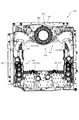
図3に示すように、パチンコ機10の背面側には、制御基板ユニット90,91と、裏パックユニット94とが主に備えられている。制御基板ユニット90は、主基板(主制御装置110)と音声ランプ制御基板(音声ランプ制御装置113)と表示制御基板(表示制御装置114)とが搭載されてユニット化されている。制御基板ユニット91は、払出制御基板(払出制御装置111)と発射制御基板(発射制御装置112)と電源基板(電源装置115)とカードユニット接続基板116とが搭載されてユニット化されている。
As shown in FIG. 3,
裏パックユニット94は、保護カバー部を形成する裏パック92と払出ユニット93とがユニット化されている。また、各制御基板には、各制御を司る1チップマイコンとしてのMPU、各種機器との連絡をとるポート、各種抽選の際に用いられる乱数発生器、時間計数や同期を図る場合などに使用されるクロックパルス発生回路等が、必要に応じて搭載されている。
The
なお、主制御装置110、音声ランプ制御装置113及び表示制御装置114、払出制御装置111及び発射制御装置112、電源装置115、カードユニット接続基板116は、それぞれ基板ボックス100〜104に収納されている。基板ボックス100〜104は、ボックスベースと該ボックスベースの開口部を覆うボックスカバーとを備えており、そのボックスベースとボックスカバーとが互いに連結されて、各制御装置や各基板が収納される。
The
また、基板ボックス100(主制御装置110)及び基板ボックス102(払出制御装置111及び発射制御装置112)は、ボックスベースとボックスカバーとを封印ユニット(図示せず)によって開封不能に連結(かしめ構造による連結)している。また、ボックスベースとボックスカバーとの連結部には、ボックスベースとボックスカバーとに亘って封印シール(図示せず)が貼着されている。この封印シールは、脆性な素材で構成されており、基板ボックス100,102を開封するために封印シールを剥がそうとしたり、基板ボックス100,102を無理に開封しようとすると、ボックスベース側とボックスカバー側とに切断される。よって、封印ユニット又は封印シールを確認することで、基板ボックス100,102が開封されたかどうかを知ることができる。
In addition, the substrate box 100 (main controller 110) and the substrate box 102 (dispensing
払出ユニット93は、裏パックユニット94の最上部に位置して上方に開口したタンク130と、タンク130の下方に連結され下流側に向けて緩やかに傾斜するタンクレール131と、タンクレール131の下流側に縦向きに連結されるケースレール132と、ケースレール132の最下流部に設けられ、払出モータ216(図4参照)の所定の電気的構成により球の払出を行う払出装置133とを備えている。タンク130には、遊技ホールの島設備から供給される球が逐次補給され、払出装置133により必要個数の球の払い出しが適宜行われる。タンクレール131には、当該タンクレール131に振動を付加するためのバイブレータ134が取り付けられている。
The
また、払出制御装置111には状態復帰スイッチ120が設けられ、発射制御装置112には可変抵抗器の操作つまみ121が設けられ、電源装置115にはRAM消去スイッチ122が設けられている。状態復帰スイッチ120は、例えば、払出モータ216(図4参照)部の球詰まり等、払出エラーの発生時に球詰まりを解消(正常状態への復帰)するために操作される。操作つまみ121は、発射ソレノイドの発射力を調整するために操作される。RAM消去スイッチ122は、パチンコ機10を初期状態に戻したい場合に電源投入時に操作される。
In addition, the
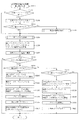
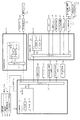
次に、図4を参照して、本パチンコ機10の電気的構成について説明する。図4は、パチンコ機10の電気的構成を示すブロック図である。
Next, the electrical configuration of the
主制御装置110には、演算装置である1チップマイコンとしてのMPU201が搭載されている。MPU201には、該MPU201により実行される各種の制御プログラムや固定値データを記憶したROM202と、そのROM202内に記憶される制御プログラムの実行に際して各種のデータ等を一時的に記憶するためのメモリであるRAM203と、そのほか、割込回路やタイマ回路、データ送受信回路などの各種回路が内蔵されている。主制御装置110では、MPU201によって、大当たり抽選や第1図柄表示装置37A,37B及び第3図柄表示装置81における表示の設定、第2図柄表示装置における表示結果の抽選といったパチンコ機10の主要な処理を実行する。
The
なお、払出制御装置111や音声ランプ制御装置113などのサブ制御装置に対して動作を指示するために、主制御装置110から該サブ制御装置へ各種のコマンドがデータ送受信回路によって送信されるが、かかるコマンドは、主制御装置110からサブ制御装置へ一方向にのみ送信される。
Although various commands are transmitted from the
RAM203は、各種エリア、カウンタ、フラグのほか、MPU201の内部レジスタの内容やMPU201により実行される制御プログラムの戻り先番地などが記憶されるスタックエリアと、各種のフラグおよびカウンタ、I/O等の値が記憶される作業エリア(作業領域)とを有している。なお、RAM203は、パチンコ機10の電源の遮断後においても電源装置115からバックアップ電圧が供給されてデータを保持(バックアップ)できる構成となっており、RAM203に記憶されるデータは、すべてバックアップされる。
The
停電などの発生により電源が遮断されると、その電源遮断時(停電発生時を含む。以下同様)のスタックポインタや、各レジスタの値がRAM203に記憶される。一方、電源投入時(停電解消による電源投入を含む。以下同様)には、RAM203に記憶される情報に基づいて、パチンコ機10の状態が電源遮断前の状態に復帰される。RAM203への書き込みはメイン処理(図示せず)によって電源遮断時に実行され、RAM203に書き込まれた各値の復帰は電源投入時の立ち上げ処理(図示せず)において実行される。なお、MPU201のNMI端子(ノンマスカブル割込端子)には、停電等の発生による電源遮断時に、停電監視回路252からの停電信号SG1が入力されるように構成されており、その停電信号SG1がMPU201へ入力されると、停電時処理としてのNMI割込処理(図示せず)が即座に実行される。
When the power is shut off due to the occurrence of a power failure or the like, the stack pointer at the time of the power shutoff (including the time of the power failure, the same applies hereinafter) and the value of each register are stored in the
主制御装置110のMPU201には、アドレスバス及びデータバスで構成されるバスライン204を介して入出力ポート205が接続されている。入出力ポート205には、払出制御装置111、音声ランプ制御装置113、第1図柄表示装置37A,37B、第2図柄表示装置、第2図柄保留ランプ、特定入賞口65aの開閉板の下辺を軸として前方側に開閉駆動するための大開放口ソレノイドや電動役物を駆動するためのソレノイドなどからなるソレノイド209が接続され、MPU201は、入出力ポート205を介してこれらに対し各種コマンドや制御信号を送信する。
An input /
また、入出力ポート205には、図示しないスイッチ群およびスライド位置検出センサSや回転位置検出センサRを含むセンサ群などからなる各種スイッチ208、電源装置115に設けられた後述のRAM消去スイッチ回路253が接続され、MPU201は各種スイッチ208から出力される信号や、RAM消去スイッチ回路253より出力されるRAM消去信号SG2に基づいて各種処理を実行する。
The input /
払出制御装置111は、払出モータ216を駆動させて賞球や貸出球の払出制御を行うものである。演算装置であるMPU211は、そのMPU211により実行される制御プログラムや固定値データ等を記憶したROM212と、ワークメモリ等として使用されるRAM213とを有している。
The
払出制御装置111のRAM213は、主制御装置110のRAM203と同様に、MPU211の内部レジスタの内容やMPU211により実行される制御プログラムの戻り先番地などが記憶されるスタックエリアと、各種のフラグおよびカウンタ、I/O等の値が記憶される作業エリア(作業領域)とを有している。RAM213は、パチンコ機10の電源の遮断後においても電源装置115からバックアップ電圧が供給されてデータを保持(バックアップ)できる構成となっており、RAM213に記憶されるデータは、すべてバックアップされる。なお、主制御装置110のMPU201と同様、MPU211のNMI端子にも、停電等の発生による電源遮断時に停電監視回路252から停電信号SG1が入力されるように構成されており、その停電信号SG1がMPU211へ入力されると、停電時処理としてのNMI割込処理(図示せず)が即座に実行される。
The
払出制御装置111のMPU211には、アドレスバス及びデータバスで構成されるバスライン214を介して入出力ポート215が接続されている。入出力ポート215には、主制御装置110や払出モータ216、発射制御装置112などがそれぞれ接続されている。また、図示はしないが、払出制御装置111には、払い出された賞球を検出するための賞球検出スイッチが接続されている。なお、該賞球検出スイッチは、払出制御装置111に接続されるが、主制御装置110には接続されていない。
An input /
発射制御装置112は、主制御装置110により球の発射の指示がなされた場合に、操作ハンドル51の回動操作量に応じた球の打ち出し強さとなるよう球発射ユニット112aを制御するものである。球発射ユニット112aは、図示しない発射ソレノイドおよび電磁石を備えており、その発射ソレノイドおよび電磁石は、所定条件が整っている場合に駆動が許可される。具体的には、遊技者が操作ハンドル51に触れていることをタッチセンサ51aにより検出し、球の発射を停止させるための発射停止スイッチ51bがオフ(操作されていないこと)を条件に、操作ハンドル51の回動操作量(回動位置)に対応して発射ソレノイドが励磁され、操作ハンドル51の操作量に応じた強さで球が発射される。
The
音声ランプ制御装置113は、音声出力装置(図示しないスピーカなど)226における音声の出力、ランプ表示装置(電飾部29〜33、表示ランプ34など)227における点灯および消灯の出力、変動演出(変動表示)や予告演出といった表示制御装置114で行われる第3図柄表示装置81の表示態様の設定などを制御するものである。演算装置であるMPU221は、そのMPU221により実行される制御プログラムや固定値データ等を記憶したROM222と、ワークメモリ等として使用されるRAM223とを有している。
The sound
音声ランプ制御装置113のMPU221には、アドレスバス及びデータバスで構成されるバスライン224を介して入出力ポート225が接続されている。入出力ポート225には、主制御装置110、表示制御装置114、音声出力装置226、ランプ表示装置227、その他装置228、枠ボタン22などがそれぞれ接続されている。その他装置228には、駆動モータ420,530,630が含まれる。
An input /
音声ランプ制御装置113は、主制御装置110から受信した各種のコマンド(変動パターンコマンド、停止種別コマンド等)に基づいて、第3図柄表示装置81の表示態様を決定し、決定した表示態様をコマンド(表示用変動パターンコマンド、表示用停止種別コマンド等)によって表示制御装置114へ通知する。また、音声ランプ制御装置113は、枠ボタン22からの入力を監視し、遊技者によって枠ボタン22が操作された場合は、第3図柄表示装置81で表示されるステージを変更したり、スーパーリーチ時の演出内容を変更したりするように、表示制御装置114へ指示する。ステージが変更される場合は、変更後のステージに応じた背面画像を第3図柄表示装置81に表示させるべく、変更後のステージに関する情報を含めた背面画像変更コマンドを表示制御装置114へ送信する。ここで、背面画像とは、第3図柄表示装置81に表示させる主要な画像である第3図柄の背面側に表示される画像のことである。表示制御装置114は、この音声ランプ制御装置113から送信されるコマンドに従って、第3図柄表示装置81に各種の画像を表示する。
The voice
また、音声ランプ制御装置113は、表示制御装置114から第3図柄表示装置81の表示内容を表すコマンド(表示コマンド)を受信する。音声ランプ制御装置113では、表示制御装置114から受信した表示コマンドに基づき、第3図柄表示装置81の表示内容に合わせて、その表示内容に対応する音声を音声出力装置226から出力し、また、その表示内容に対応させてランプ表示装置227の点灯および消灯を制御する。
Further, the sound
表示制御装置114は、音声ランプ制御装置113及び第3図柄表示装置81が接続され、音声ランプ制御装置113より受信したコマンドに基づいて、第3図柄表示装置81における第3図柄の変動演出などの表示を制御するものである。また、表示制御装置114は、第3図柄表示装置81の表示内容を通知する表示コマンドを適宜音声ランプ制御装置113へ送信する。音声ランプ制御装置113は、この表示コマンドによって示される表示内容にあわせて音声出力装置226から音声を出力することで、第3図柄表示装置81の表示と音声出力装置226からの音声出力とをあわせることができる。
The
電源装置115は、パチンコ機10の各部に電源を供給するための電源部251と、停電等による電源遮断を監視する停電監視回路252と、RAM消去スイッチ122(図3参照)が設けられたRAM消去スイッチ回路253とを有している。電源部251は、図示しない電源経路を通じて、各制御装置110〜114等に対して各々に必要な動作電圧を供給する装置である。その概要としては、電源部251は、外部より供給される交流24ボルトの電圧を取り込み、各種スイッチ208などの各種スイッチや、ソレノイド209などのソレノイド、モータ等を駆動するための12ボルトの電圧、ロジック用の5ボルトの電圧、RAMバックアップ用のバックアップ電圧などを生成し、これら12ボルトの電圧、5ボルトの電圧及びバックアップ電圧を各制御装置110〜114等に対して必要な電圧を供給する。
The
停電監視回路252は、停電等の発生による電源遮断時に、主制御装置110のMPU201及び払出制御装置111のMPU211の各NMI端子へ停電信号SG1を出力するための回路である。停電監視回路252は、電源部251から出力される最大電圧である直流安定24ボルトの電圧を監視し、この電圧が22ボルト未満になった場合に停電(電源断、電源遮断)の発生と判断して、停電信号SG1を主制御装置110及び払出制御装置111へ出力する。停電信号SG1の出力によって、主制御装置110及び払出制御装置111は、停電の発生を認識し、NMI割込処理を実行する。なお、電源部251は、直流安定24ボルトの電圧が22ボルト未満になった後においても、NMI割込処理の実行に充分な時間の間、制御系の駆動電圧である5ボルトの電圧の出力を正常値に維持するように構成されている。よって、主制御装置110及び払出制御装置111は、NMI割込処理(図示せず)を正常に実行し完了することができる。
The power
RAM消去スイッチ回路253は、RAM消去スイッチ122(図3参照)が押下された場合に、主制御装置110へ、バックアップデータをクリアさせるためのRAM消去信号SG2を出力するための回路である。主制御装置110は、パチンコ機10の電源投入時に、RAM消去信号SG2を入力した場合に、バックアップデータをクリアすると共に、払出制御装置111においてバックアップデータをクリアさせるための払出初期化コマンドを払出制御装置111に対して送信する。
The RAM erase
次いで、図5及び図6を参照して、ユニット収納部材300について説明する。図5及び図6は、ユニット収納部材300の正面図であり、図5では各動作ユニット400〜800が退避位置に配置された状態が、図6では突出動作ユニット400及び複合動作ユニット500が張出位置に配置された状態が、それぞれ図示される。
Next, the
図5及び図6に示すように、ユニット収納部材300は、正面視矩形の底壁板と、その底壁部の4辺の外縁から立設される外壁板とから正面側(図5紙面手前側)が開放された箱状に形成される。ユニット収納部材300の底面板には、その中央部分に正面視矩形の開口301が開口形成され、これにより、ユニット収納部材300が正面視矩形の枠状に形成される。なお、開口301は、第3図柄表示装置81(図2参照)の外形に対応した(即ち、第3図柄表示装置81を配設可能な)大きさに形成される。
As shown in FIG. 5 and FIG. 6, the
ユニット収納部材300には、その内部空間に、突出動作ユニット400、複合動作ユニット500、回転動作ユニット600、出没動作ユニット700及び張出動作ユニット800がそれぞれ収納され、これにより動作ユニット200が1ユニットとして構成される。
In the
突出動作ユニット400は、基側変位部材440及び相対変位部材450を備え、それら両変位部材440,450を、図5に示す退避位置と図6に示す張出位置との間で動作(変位)させる。図5に示す退避位置では、基側変位部材440及び相対変位部材450が前後方向(図5紙面垂直方向)で重ねられた状態を形成することで、退避位置に必要とされるスペースを抑制する一方、図6に示す張出位置では、相対変位部材450を基側変位部材440に対してスライド変位させ、全体を大型化することで、視認性を確保して、演出効果を高める。この突出動作ユニット400の動作については、図7から図17を参照して後述する。
The
複合動作ユニット500は、被駆動部材550(図20及び図21参照)及び従動部材560を備え、それら両部材550,560を、図5に示す退避位置と図6に示す張出位置との間で動作(変位)させる。この場合、複合動作ユニット500は、被駆動部材550には、所定位置を回転中心とする回転運動のみを行わせる一方で、その被駆動部材550に接続される従動部材560には、直線運動と回転運動とを組み合わせた運動を行わせることで、従動部材560の軌道に変化を付与して、演出効果を高める。この複合動作ユニット500の動作については、図18から図32を参照して後述する。
The combined
回転動作ユニット600は、同心に配設される第1回転体650及び第2回転体660を備え、それら両回転体650,660を回転させることで、両者の回転を遊技者に関連付けさせやすくして、複数の回転体(第1回転体650及び第2回転体660)をそれぞれ回転させるという演出の効果を発揮させる。この回転動作ユニット600の動作については、図33から図39を参照して後述する。
The
また、出没動作ユニット700はスライド変位可能に形成される出没部材710を、張出動作ユニット800は、回転可能に形成される張出部材810を、それぞれ備え、それら出没部材710及び張出部材810を、図5に示す退避位置と開口301(第3図柄表示装置81、図2参照)の正面(前面)に張り出した状態となる張出位置(図示せず)との間でスライド変位または回転により動作(変位)させる。
In addition, the projecting
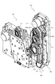
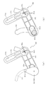
次いで、図7から図17を参照して、突出動作ユニット400について説明する。図7は、基側変位部材440及び相対変位部材450が退避位置に配置された状態における突出動作ユニット400の正面斜視図である。図8(a)は、突出動作ユニット400の分解正面斜視図であり、図8(b)は、連結ロッド460の背面斜視図である。
Next, the protruding
なお、図7及び図8では、突出動作ユニット400とケース体410を共用する出没動作ユニット700が突出動作ユニット400に併設された状態が図示される。また、突出動作ユニット400は、開口301の下方において出没動作ユニット700を挟んで左右に一対が配設されるところ(図5及び図6参照)、これら一対の突出動作ユニット400は左右対称に形成され、その構造は実質的に同一であるので、一方(正面視右側に配設されるもの)についてのみ説明し、他方(正面視左側に配設されるもの)についての説明は省略する。
7 and 8 show a state in which the projecting
図7及び図8に示すように、突出動作ユニット400は、その背面側において骨格をなすケース体410と、そのケース体410の正面側に配設される駆動モータ420と、その駆動モータ420の回転駆動力を伝達する複数の歯車(ピニオンギヤ431、中間ギヤ432及びクランクギヤ433)と、ケース体410に回転可能に軸支される基側変位部材440と、その基側変位部材440にスライド変位可能に配設される相対変位部材450と、その相対変位部材450及びクランクギヤ433の間を連結すると共にケース体410に回転可能に軸支される連結ロッド460と、を主に備えて構成される。
As shown in FIGS. 7 and 8, the
ケース体410は、樹脂材料からなり、そのケース体410の正面(前面)には、複数の歯車(各ギヤ431,432,433)に対応した外形を有する収納凹部411が凹設されると共に、その収納凹部411の側方(図8(a)右側)にロッド支持軸412が、収納凹部411の下方(図8(a)下側)に基側支持軸413が、それぞれ突設される。なお、各支持軸412,413は、真鍮材料からなり、各ギヤ431〜433の回転軸と平行な姿勢で配設される。
The
本実施形態では、基側変位部材440及び相対変位部材450が退避位置に配置されると、後述するように、各変位部材440,450と、連結ロッド460と、各ギヤ431,432,433とが前後方向に積層される構造であるところ(図13参照)、ケース体410の正面に収納凹部411を凹設し、その収納凹部411に各ギヤ431,432,433をそれぞれ収納する構造とすることで、その分、突出動作ユニット400の前後方向の小型化を図ることができる。
In this embodiment, when the base
駆動モータ420の駆動軸には、ピニオンギヤ431が取着され、そのピニオンギヤ431には中間ギヤ432が、中間ギヤ432にはクランクギヤ433が、それぞれ歯合される。よって、駆動モータ420の駆動軸が回転駆動され、ピニオンギヤ431が回転されると、その回転が中間ギヤ432を介して、クランクギヤ433に伝達され、クランクギヤ433が回転される。
A
なお、中間ギヤ432及びクランクギヤ433は、ケース体410に軸支される。また、各ギヤ431〜433は、歯が回転軸と平行に外周面に刻設される平歯車としてそれぞれ形成される。この場合、クランクギヤ433は、その正面(軸方向端面)に放射状の装飾が形成されると共に、正面部分(軸方向端面)の直径が、外周面に刻設される歯の歯先円よりも大きくされ、正面視において遊技者から歯を遮蔽可能に形成される。
The
クランクギヤ433の正面(軸方向端面)には、そのクランクギヤ433の回転軸から偏心した位置にクランクピン433aが突設される。クランクピン433aは、連結ロッド460に連結される部位であり、クランクギヤ433の回転軸に平行な円柱状体として形成されると共に、連結ロッド460のロッド溝463内に摺動可能に挿通される(図9及び図10参照)。これにより、クランクギヤ433が回転されると、その回転が、クランクピン433aを介して、連結ロッド460へ伝達される。
On the front surface (axial end surface) of the
基側変位部材440及び相対変位部材450は、退避位置から張出位置へ変位されることで演出を行うための演出部材であり(図5及び図6参照)、基側変位部材440(軸支孔442)がケース体410の基側支持軸413に回転可能に軸支されると共に、基側変位部材440の正面側に相対変位部材450がスライド変位可能に配設される。
The base
ここで、相対変位部材450には、その正面側に装飾部454が形成される。装飾部454は、相対変位部材450の正面側を装飾するための部位であり、基端側(基側変位部材440が回転される際の回転中心側、図7及び図8の下側)から先端側(基端変位部材440が回転される際の回転先端側、図7及び図8の上側)へ向かうに従って幅が狭くなる正面視先細形状に全体が形成されると共に、装飾部454の正面には、第1部分454a、第2部分454b及び第3部分454cが長手方向に沿って列設される。
Here, the
これら装飾部454の第1部分454a、第2部分454b及び第3部分454cは、装飾部454全体の先細形状に対応した大きさに形成される。即ち、先端側に位置する第1部分454aよりも中間に位置する第2部分454bが、中間に位置する第2部分454bよりも基端側に位置する第3部分454cが、それぞれ外形の大きな六角形に形成される。
The
この場合、第1部分454a、第2部分454b及び第3部分454cは、その前後方向の位置(図5紙面垂直方向の位置)をそれぞれ異なせて配置される。具体的には、先端側に位置する第1部分454aよりも中間に位置する第2部分454bが、中間に位置する第2部分454bよりも基端側に位置する第3部分454cが、それぞれ正面(前方)側(図5紙面手前側)に配置される。
In this case, the
これにより、相対変位部材450の装飾部454(即ち、相対変位部材450の正面)は、基端側(基側変位部材440の回転中心側、図7及び図8の下側)から先端側(基端変位部材440の回転先端側、図7及び図8の上側)へ向かうに従ってケース体410に近接する方向へ階段状(本実施形態では3段の階段状)に下降傾斜される。
Accordingly, the
これにより、後述するように、基側変位部材440を回転させる際には(図13及び図14参照)、装飾部材480(図16及び図17参照)との接触を防止しつつ、装飾部材480の背面側を両変位部材440,450が通過する態様を可能として、演出効果の向上を図ると共に、相対変位部材450を張り出させる際には(図15参照)、装飾部454を正面(前方)に位置させ、迫力の向上を図ることができる。
Thus, as will be described later, when the base-
なお、基側変位部材440及び相対変位部材450の詳細構成については後述する(図11及び図12参照)。
The detailed configuration of the base
連結ロッド460は、クランクギヤ433の回転を相対変位部材450へ伝達するための長尺板状の部材であり、長手方向一端側に円形の孔として穿設される軸支孔461と、その軸支孔461と反対側となる長手方向他端側に長手方向に沿って延設される長穴として穿設される接続孔462と、それら軸支孔461及び接続孔462の間において長手方向に沿って延設される凹溝として背面側に凹設されるロッド溝463と、を備えて形成される。
The connecting
連結ロッド460は、軸支孔461にケース体410のロッド支持軸412が挿通されると共に、ロッド溝463にクランクギヤ433のクランクピン433aが挿通される状態で、ケース体410に取り付けられる。また、連結ロッド460の接続孔462には、相対変位部材450の接続ピン452が挿通される(図11及び図12参照)。これにより、後述するように、クランクギヤ433の回転に伴い、ロッド支持軸412を回転中心として連結ロッド460が回転されると共に(図9及び図10参照)、その連結ロッド460の回転に伴い、基側変位部材440及び相対変位部材450が回転(第1動作)及びスライド変位(第2動作)され(図12参照)、退避位置と張出位置との間で動作(変位)される。
The connecting
この場合、本実施形態では、図7に示すように、ケース体410の正面(一面)側に駆動モータ420と基側変位部材440及び相対変位部材450とがそれぞれ配設されるので、例えば、ケース体410を挟んで、正面(一面)側に基側変位部材440及び相対変位部材450が、背面(他面)側に駆動モータ420が、それぞれ配設される場合と比較して、突出動作ユニット400の前後方向における寸法の小型化を図ることができる。
In this case, in the present embodiment, as shown in FIG. 7, the
更に、基側変位部材440及び相対変位部材450は、その長手方向の延長線上に駆動モータ420が位置する姿勢で、退避位置に配設されるので(図13(a)参照)、これら駆動モータ420と基側変位部材440及び相対変位部材450とを直線状に配置できる。よって、ケース体410の正面側に退避位置として必要とされるスペースを効率的に抑制できる。
Furthermore, since the base
また、本実施形態では、駆動モータ420の回転駆動力を基側変位部材440及び相対変位部材450へ伝達するための伝達手段を、複数の歯車(各ギヤ431〜433)及びクランクギヤ433と共にクランク機構をなす連結ロッド460から構成し、後述するように、連結ロッド460(接続孔462及びロッド溝463)とクランクギヤ433のクランクピン433a及び相対変位部材450の接続ピン452とが接続される部分が、ケース体410のロッド支持軸412及び基側支持軸413の間となる領域内に配置されるように、伝達手段(各ギヤ431〜433及び連結ロッド460)及び各支持軸411,412の配置を設定する。
In the present embodiment, the transmission means for transmitting the rotational driving force of the
これにより、基側変位部材440及び相対変位部材450が退避位置に配設された状態において、これら基側変位部材440及び相対変位部材450に対して正面視において重なる領域内に伝達手段を配設することができる。即ち、退避位置に配設された基側変位部材440及び相対変位部材450の背面側に形成されるデッドスペースを、伝達手段の配設スペースとして有効に活用できる。その結果、上述した駆動モータ420と基側変位部材440及び相対変位部材450との位置関係による効果と共に、突出動作ユニット400の前後方向および正面視における外形の小型化を相乗的に達成することができる。
Thereby, in a state where the base
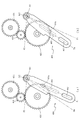
次いで、図9及び図10を参照して、伝達手段(ピニオンギヤ431、中間ギヤ432、クランクギヤ433及び連結ロッド460)の動作について説明する。図9及び図10は、正面視における伝達手段を模式的に図示した正面模式図であり、図9(a)ではクランクギヤ433が第1回転位置に配置された状態が、図9(b)ではクランクギヤ433が中間回転位置に配置された状態が、図10ではクランクギヤ433が第2回転位置に配置された状態が、それぞれ図示される。
Next, the operation of the transmission means (
なお、図9及び図10では、図面を簡素化して、理解を容易とするために、各ギヤ431〜433及び連結ロッド460の形状が模式的に図示される。また、図9及び図10には、クランクギヤ433が第1回転位置、中間回転位置および第2回転位置に配置された際の連結ロッド460の中心線の位置が位置P1,Pm,P2として二点鎖線を用いて模式的に図示される。
9 and 10, the shapes of the
また、図9及び図10の説明においては、図13から図15を適宜参照する。図9(a)は、図13(a)及び図13(b)に示す状態に対応し、図9(b)は、図14(a)及び図14(b)に示す状態に対応し、図10は、図15(a)及び図15(b)に示す状態に対応する。 Moreover, in description of FIG.9 and FIG.10, FIG. 13-FIG. 15 is referred suitably. 9A corresponds to the state shown in FIGS. 13A and 13B, and FIG. 9B corresponds to the state shown in FIGS. 14A and 14B. FIG. 10 corresponds to the state shown in FIGS. 15 (a) and 15 (b).
図9(a)に示すように、このクランクギヤ433が第1回転位置に配置され、連結ロッド460が位置P1に位置する状態では、基側変位部材440が退避位置に、相対変位部材450が基準位置に、それぞれ配置される(図12(a)及び図13参照)。この状態では、クランクギヤ433のクランクピン433aが、連結ロッド460のロッド溝463における上端(ロッド支持軸412側の端部)に位置する。
As shown in FIG. 9A, in a state where the
よって、クランクギヤ433が第1回転位置に配置された状態では、クランクギヤ433が図9(a)左回り(反時計回り)へ回転(即ち、基側変位部材440及び相対変位部材450を張出位置から退避位置へ退避させる方向へ回転)することを、クランクピン433aをロッド溝463の上端に当接させることで、規制できる。従って、基側変位部材440及び相対変位部材450を張出位置から退避位置へ配置する際に、例えば、電気的な要因により、駆動モータ420の制御不良が発生した場合であっても、機械的な機構(クランクピン433aをロッド溝463で規制するストッパ機構)により、基側変位部材440及び相対変位部材450が退避位置を越えて変位され、これら両変位部材440,450や連結ロッド460が他の部材に衝突することを未然に回避できる。
Therefore, when the
図9(a)に示す状態からクランクギヤ433が図9(a)右回り(時計回り)に回転されると、クランクギヤ433のクランクピン433aが、連結ロッド460のロッド溝463を下端(ロッド支持軸412と反対側の端部)へ向けて摺動され、連結ロッド460がロッド支持軸412を回転中心として図9(a)右回り(時計回り)に回転される。クランクギヤ433が更に回転され、図9(b)に示すように、中間回転位置に達すると、連結ロッド460が位置Pmに位置される。この状態では、基側変位部材440が回転位置に、相対変位部材450が基準位置に、それぞれ配置される(図12(b)及び図14参照)。
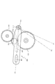
When the
図9(b)に示す状態からクランクギヤ433が図9(a)右回り(時計回り)に回転されると、クランクギヤ433のクランクピン433aが、連結ロッド460のロッド溝463を下端(ロッド支持軸412と反対側の端部)へ向けて摺動した後に上端(ロッド支持軸412側の端部)へ向けて摺動され、連結ロッド460がロッド支持軸412を回転中心として図9(a)右回り(時計回り)に回転される。これにより、クランクギヤ433が、図10に示すように、第2回転位置に達すると、連結ロッド460が位置P2に位置される。この状態では、基側変位部材440が回転位置に、相対変位部材450が張出位置に、それぞれ配置される(図12(c)及び図15参照)。
When the
なお、このクランクギヤ433が第2回転位置に配置された場合においても、図9(a)に示す第1回転位置に配置された場合と同様に、クランクギヤ433のクランクピン433aが、連結ロッド460のロッド溝463における上端(ロッド支持軸412側の端部)に位置する。
Even when the
よって、クランクギヤ433が第2回転位置に配置された状態では、クランクギヤ433が図10右回り(時計回り)へ回転(即ち、基側変位部材440及び相対変位部材450を退避位置から張出位置へ張り出させる方向へ回転)することを、クランクピン433aをロッド溝463の上端に当接させることで、規制できる。従って、基側変位部材440及び相対変位部材450を退避位置から張出位置へ配置する際に、例えば、電気的な要因により、駆動モータ420の制御不良が発生した場合であっても、機械的な機構(クランクピン433aをロッド溝463で規制するストッパ機構)により、基側変位部材440及び相対変位部材450が張出位置を越えて変位され、これら両変位部材440,450や連結ロッド460が他の部材に衝突することを未然に回避できる。
Therefore, when the
次いで、図11及び図12を参照して、基側変位部材440及び相対変位部材450の構成およびその動作について説明する。図11は、基側変位部材440及び相対変位部材450の分解背面斜視図である。
Next, with reference to FIGS. 11 and 12, the configuration and operation of the
図11に示すように、基側変位部材440は、長尺板状に形成される本体部441と、その本体部411の背面に円形の孔として開口される軸支孔442と、本体部441の長手方向(図11上下方向)に沿って延設される長穴として穿設される第1スライド孔443及び第2スライド孔444と、を主に備えて形成される。
As shown in FIG. 11, the base
軸支孔442は、ケース体410の基側支持軸413が挿通される孔であり、かかる挿通により、基側変位部材440は、基側支持軸413を回転中心として、ケース体410に回転可能に軸支される。即ち、基側変位部材440は、後述するように、退避位置(図12(a)及び図13参照)と回転位置(図12(b)、図12(c)、図14及び図15参照)との間で回転可能に軸支される。
The
この場合、軸支孔442は、本体部441の長手方向中央よりも下方側であって、本体部441の幅方向中央よりも一側(張出位置側)へ偏った位置に形成される。これにより、基側変位部材440及び相対変位部材450がケース体410の外縁から所定量(所定面積)だけ張り出すために基側変位部材440に必要とされる回転角度を小さくできるので、基側変位部材440を退避位置と回転位置との間で回転させるのに必要な時間を短縮でき、その結果、基側変位部材440及び相対変位部材450の変位による演出効果を高めることができる。
In this case, the
相対変位部材450は、長尺板状に形成される本体部451と、その本体部の背面から突出される接続ピン452と、本体部451の長手方向(図11上下方向)に沿って所定間隔を隔てつつ配置される一対のスライドピン453と、本体部451の正面に配設される装飾部454と、を主に備えて形成される。
The
接続ピン452及びスライドピン453は、基側変位部材440の第1スライド孔443及び第2スライド孔444にそれぞれ摺動可能に挿通される円柱状の部位であり、かかる挿通により、相対変位部材450が基側変位部材440に対しその長手方向に沿ってスライド変位可能に配設される。即ち、相対変位部材450は、後述するように、基準位置(図12(a)、図12(b)、図13及び図14参照)と張出位置(図12(c)及び図15参照)との間でスライド変位可能に基側変位部材440に配設される。
The
この場合、接続ピン452は、基側変位部材440の第1スライド孔443から突出される先端側が、連結ロッド460の接続孔462に摺動可能に挿通され、かかる挿通により、相対変位部材450が連結ロッド460を介してクランクギヤ433(図8参照)に接続される。
In this case, the
これにより、後述するように、クランクギヤ433の回転により、ロッド支持軸412を回転中心として連結ロッド460を回転させることで(図9参照)、基側支持軸413を回転中心とした基側相対変位部材450の回転(第1動作)を実行できると共に、基側変位部材440に対する相対変位部材450のスライド変位(第2動作)を実行できる(図12参照)。
Thus, as will be described later, by rotating the
ここで、接続ピン452とスライドピン453とは、相対変位部材450の長手方向(図11上下方向)に沿って位置を違えて(間隔を隔てて)配設される。よって、相対変位部材450が基側変位部材440に連結される箇所を長手方向に分散させることができるので、基側変位部材440に対する相対変位部材450の前後方向(ケース体410に近接離間する方向)の相対変位を抑制して、スライド変位を安定させることができる。
Here, the
また、接続ピン452は、スライドピン453よりも相対変位部材450の長手方向先端側(図11上側)に配置される。これにより、相対変位部材450が連結ロッド460を介してケース体410に支持される箇所を、相対変位部材450の長手方向先端側に近づけることができる。換言すると、相対変位部材450が連結ロッド460を介してケース体410に支持される箇所を、基側変位部材440の軸支孔442から長手方向先端側(図11上側)へ遠ざけることができる。その結果、相対変位部材450の先端側が前後方向(ケース体410に近接離間する方向)に揺れることを抑制しやすくできる。
Further, the
即ち、基側変位部材440の長手方向基側(軸支孔442)のみがケース体410の基側支持軸413に軸支され、その基側変位部材440に相対変位部材450が配設される構造であるため、両変位部材440,450の長手方向先端側が自由端となり、第1動作の最中に先端側が前後方向に揺れやすい。この揺れは、先端側を装飾部材480と接触させるおそれを生じる。そのため、連結ロッド460を介してケース体410に支持させる位置を長手方向先端側とする構造が有効となる。
That is, only the longitudinal direction base side (the shaft support hole 442) of the base
接続ピン452及びスライドピン453には、カラーCが回転自在に外嵌される。接続ピン452及びスライドピン453の外周面と第1スライド孔443及び第2スライド孔444の内周面との間にカラーCが介在されることで、これら各スライド孔443,444に沿って各ピン452,453をスムーズに摺動させることができる。また、基側変位部材440の本体部441と相対変位部材450の本体部451及び連結ロッド460との間にカラーC(詳細には、カラーCの大径のフランジ部分)が介在されることで、これら基側変位部材440と相対変位部材450及び連結ロッド460との間の対向間隔を一定に保持することができる。
A collar C is rotatably fitted on the
なお、接続ピン452は、その先端側の端面に円板状の円板Sがねじにより締結固定されることで、連結ロッド460からの抜け止めとされ、スライドピン453は、その先端側の端面に長尺平板状のスライドガイド470がねじにより締結固定され、基側変位部材440からの抜け止めとされる。
The
図12は、基側変位部材440及び相対変位部材450の背面斜視図である。なお、図12(a)は、図9(a)及び図13に図示する状態(即ち、クランクギヤ433が第1回転位置に、連結ロッド460が位置P1に、それぞれ配置された状態)に対応し、図12(b)は、図9(b)及び図14に図示する状態(即ち、クランクギヤ433が中間回転位置に、連結ロッド460が位置Pmに、それぞれ配置された状態)に対応する。また、図12(c)は、図10及び図15に図示する状態(即ち、クランクギヤ433が第2回転位置に、連結ロッド460が位置P2に、それぞれ配置された状態)に対応する。
FIG. 12 is a rear perspective view of the base
図12(a)に示すように、連結ロッド460が位置P1に位置する状態では(図9(a)及び図13参照)、基側変位部材440の基側支持軸413を回転中心とする回転位置が、ロッド支持軸412に最も近接する位置である退避位置に、相対変位部材450の基側変位部材440に対するスライド位置が、基側変位部材440からの張り出し量が最少となる位置である基準位置に、それぞれ配置される。この状態では、相対変位部材450の接続ピン452が、連結ロッド460の接続孔462における上端(ロッド支持軸412側の端部)に位置する。
As shown in FIG. 12 (a), when the connecting
図12(a)に示す状態から、クランクギヤ433(図9(a)参照)の回転により、連結ロッド460がロッド支持軸412を回転中心として図12(a)左回り(反時計回り)に回転されると、相対変位部材450の接続ピン452が、連結ロッド460の接続孔462を下端(ロッド支持軸412と反対側の端部)へ向けて摺動され、基側変位部材440及び相対変位部材450が基側支持軸413を回転中心として、基側変位部材440が相対変位部材450と共に図12(a)右回り(時計回り)に回転される(第1動作)。連結ロッド460が更に回転され、図12(b)に示すように、中間位置Pmに達すると(図9(b)及び図14参照)、基側変位部材440の回転位置が、ロッド支持軸412から最も離間した位置である回転位置に配置される。
From the state shown in FIG. 12A, the connecting
この場合、相対変位部材450の基側変位部材440に対するスライド位置は、基準位置に維持できる。即ち、連結ロッド460のロッド支持軸412を回転中心とする図12(a)左回り(反時計回り)の回転は、相対変位部材450の接続ピン452を、連結ロッド460の接続孔462を下端へ向けて摺動させるところ、この摺動の方向が基側変位部材440に対する相対変位部材450のスライド変位の方向にほぼ沿う方向であるため、相対変位部材450を基側変位部材440に対してスライド変位させる方向への力成分を発生させない。よって、基側変位部材440に対する相対変位部材450のスライド位置を維持しつつ(基準位置からのスライド変位の発生を規制しつつ)、基側支持軸413を回転中心とする基側変位部材440の回転のみを発生させることができる。
In this case, the slide position of the
これにより、基側変位部材440からの相対変位部材450の張り出し量が最少に維持された状態で、これら両変位部材440,450を、基側支持軸413を中心として回転させることができるので、相対変位部材450の回転先端と駆動モータ420(図7参照)や装飾部材480(図16及び図17参照)との間の離間距離を小さくすることができる。その結果、突出動作ユニット400の小型化を図ることができると共に、装飾部材480の形状を規定する際の設計の自由度を高めることができる。
As a result, both the
図12(b)に示す状態から、クランクギヤ433(図9(b)参照)の回転により、連結ロッド460がロッド支持軸412を回転中心として図12(b)左回り(反時計回り)に回転されると、相対変位部材450の接続ピン452が、連結ロッド460の接続孔462を上端(ロッド支持軸412側の端部)へ向けて摺動された後に下端(ロッド支持軸412と反対側の端部)へ向けて摺動され、基側変位部材440に対して相対変位部材450が長手方向(第1及び第2スライド孔443,444)に沿って伸長する方向へスライド変位される(第2動作)。これにより、連結ロッド460が、図12(c)に示すように、第2位置P2に達すると(図10及び図15参照)、相対変位部材450の基側変位部材440に対するスライド位置が、基側変位部材440からの張り出し量が最大となる位置である張出位置に配置される。
From the state shown in FIG. 12 (b), the connecting
この場合、基側変位部材440の回転位置は、ロッド支持軸412から最も離間した位置である回転位置に維持できる。即ち、連結ロッド460のロッド支持軸412を回転中心とする図12(b)左回り(反時計回り)の回転は、相対変位部材450の接続ピン452を、連結ロッド460の接続孔462に沿って摺動させるところ、この摺動の方向が基側変位部材440に対する相対変位部材450のスライド変位の方向にほぼ直交する方向であるため、相対変位部材450を基側変位部材440に対してスライド変位させる方向への力成分のみを発生させ、基側支持軸413を回転中心として基側変位部材440を回転させる方向への力成分を発生させない。よって、基側支持軸413を回転中心とする基側変位部材440の回転を規制しつつ、基側変位部材440に対する相対変位部材450のスライド変位のみを発生させることができる。
In this case, the rotational position of the base-
これにより、基側変位部材440からの相対変位部材450の張り出し量が最少に維持された状態(相対変位部材450が基準位置に維持された状態)で、基側変位部材440を退避位置から回転位置へ回転させ(第1動作)、その第1動作が完了した後に、基側変位部材440の回転は規制した状態(基側変位部材440が回転位置に維持された状態)で、相対変位部材450を基側変位部材440に対して長手方向に沿って伸長させるスライド変位(第2動作)を行うことができる。即ち、回転動作とスライド動作とを分離して、それぞれを別々の動作として2段階で行うことができるので、これら回転動作およびスライド動作が同時に行われる場合と比較して、異なる態様の動作を遊技者に明確に認識させることができ、各変位部材440,450を変位させることによる演出効果を高めることができる。
Thereby, the
以上のように構成された突出動作ユニット400の動作について、図13から図15を参照して説明する。
The operation of the projecting
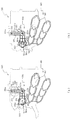
図13から図15は、突出動作ユニット400の正面図である。なお、上述したように、図13(a)及び図13(b)は、図9(a)及び図12(a)に示す状態に対応し、図14(a)及び図14(b)は、図9(b)及び図12(b)に示す状態に対応し、図15(a)及び図15(b)は、図10及び図12(c)に示す状態に対応する。また、図13(b)、図14(b)及び図15(b)では、基側変位部材440及び相対変位部材450が取り外された状態が図示される。
13 to 15 are front views of the protruding
図13から図15に示すように、突出動作ユニット400によれば、上述したように、基側変位部材440が、図13(a)に示す退避位置と図14(a)及び図15(a)に示す回転位置との間で回転可能に形成されると共に、その基側変位部材440に配設される相対変位部材450が、図13(a)及び図14(a)に示す基準位置と図15(a)に示す張出位置との間でスライド変位可能に形成され、基側変位部材440を退避位置および回転位置の間で回転させる第1動作と、相対変位部材450を基側変位部材440に対して基準位置および張出位置の間で変位させる第2動作と、がそれぞれ実行可能とされる。
As shown in FIGS. 13 to 15, according to the
これにより、図13(a)及び図14(a)に示すように、退避位置にある基側変位部材440を第1動作により回転位置へ配置し、基準位置にある相対変位部材450を第2動作により張出位置へスライド変位させる(伸長させる)ことで、図15(a)に示すように、かかる相対変位部材450を基側変位部材440から外方へ張り出させることができる。よって、その分、基側変位部材440及び相対変位部材450を全体として大きくできるので、かかる両変位部材440,450を遊技者に十分に視認させ、その演出効果を十分に発揮させることができる。
As a result, as shown in FIGS. 13A and 14A, the base
特に、本実施形態では、図14(a)に示すように、基側変位部材440を第1動作により回転位置へ配置することで、相対変位部材450の先端部分(本実施形態では、装飾部454の第1部分454aの全体)をセンターフレーム86の開口部を介して遊技者に視認させることができ、図15(a)に示すように、相対変位部材450を第2動作により張出位置に配置することで、相対変位部材450の略全体(本実施形態では打装飾部454の第3部分454aの全体)をセンターフレーム86の開口部を介して遊技者に視認させることができる。
In particular, in the present embodiment, as shown in FIG. 14A, the distal end portion of the relative displacement member 450 (in the present embodiment, the decorative portion) is arranged by arranging the base
即ち、退避位置に退避され、センターフレーム86の開口部からは視認不能とされていた相対変位部材450を、まず、回転運動(第1動作)によりセンターフレーム86の開口部に側方から登場させ、その相対変位部材450の一部のみを遊技者に視認させると共に、次いで、直線運動(第2動作)によりセンターフレーム86の開口部の中央へ向けて張り出させて、相対変位部材450の略全体を遊技者に視認させるという演出を行うことができる。よって、登場時の運動形態(回転運動)とは異なる運動形態(直線運動)により相対変位部材450の視認面積を拡大させることができ、運動形態の変化による意外性と、直線運動により視認面積が拡大されることによるスピード感と、これらが組み合わされつつ連続して行われることによる複合動作の一体感とを遊技者に感じさせることができる。その結果、相対変位部材450が単に直線運動のみによりセンターフレーム86の開口部に対して出没する形態(退避位置と張出位置とを往復する形態)では奏し得ない演出効果を得ることができる。
That is, the
一方、回転位置にある基側変位部材を第1動作により図13(a)に示す退避位置へ配置する際には、図14(a)及び図15(b)に示すように、張出位置による相対変位部材450を第2動作により基準位置にスライド変位させる(短縮させる)ことで、かかる相対変位部材450の基側変位部材440からの外方への張り出しを抑制できる。よって、その分、両変位部材440,450を全体として小さくできるので、退避位置において、両変位部材440,450を収容するために必要とされるスペースを抑制できる。その結果、他の部品や装置を配設するためのスペースを確保することができる。
On the other hand, when the base-side displacement member at the rotational position is disposed at the retracted position shown in FIG. 13A by the first operation, as shown in FIGS. By causing the
この場合、上述したように、相対変位部材450が基側変位部材440にスライド変位可能な状態で配設され、第2動作が、図14(a)及び図15(a)に示すように、相対変位部材440を基側変位部材450に対して基準位置および張出位置の間でスライド変位させる態様であるので、例えば、第2動作が、相対変位部材440を基側変位部材450に対して回転させる態様である場合と比較して、相対変位部材440を基準位置から張出位置まで変位させるのに必要なスペースを抑制することができ、その分、他の部品や装置を配設するためのスペースを確保することができる。また、第1動作による基側変位部材450の変位の態様(回転)に対して、第2動作による相対変位部材450の変位の態様(スライド変位)を、異なる態様とすることができるので、第1動作および第2動作を連続して行うことによる演出効果を高めることができる。
In this case, as described above, the
特に、かかる第2動作は、そのスライド変位の方向が両変位部材440,450の互いの長手方向に沿った方向とされる。即ち、基側変位部材440に対して相対変位部材450が互いの長手方向を沿わせた姿勢で配設され、それら互いの長手方向に沿った方向にスライド変位されるので、両変位部材440,450を全体として効率的に伸長および短縮させることができる。よって、図15(a)に示すように、基側変位部材440が回転位置に配置された状態では、相対変位部材450のスライド変位(伸長)により、全体として大きくすることで、両変位部材440,450を遊技者に十分に視認させることができ、その演出効果を十分に発揮させることができる。一方、図13(a)に示すように、基側変位部材440が退避位置に配置された状態では、相対変位部材450のスライド変位(短縮)により、全体として小さくすることで、両変位部材440,450を収容するために必要とされるスペースを抑制でき、他の部品や装置を配設するためのスペースを確保することができる。
Particularly, in the second operation, the direction of the slide displacement is a direction along the longitudinal direction of the both
また、突出動作ユニット400によれば、上述したように、駆動モータ420の回転駆動力を基側変位部材440及び相対変位部材450に伝達する伝達手段が、図13(a)、図14(b)及び図15(b)に示すように、複数の歯車(ピニオンギヤ431、中間ギヤ432及びクランクギヤ433)及び連結ロッド460からなり、クランクギヤ433と共にクランク機構を構成する連結ロッド460の接続孔462を、連結ロッド460の回転中心であるロッド支持軸412と基側変位部材440の回転中心である基側支持軸413との間となる領域内において、相対変位部材450の接続ピン452に接続するので、クランクギヤ433を回転させることで、基側変位部材440及び相対変位部材450による第1動作と第2動作とを、順に実行することができる。即ち、第1動作および第2動作という異なる2の動作を1の駆動モータ420のみにより行うことができるので、部品コストを削減して、その分、製品コストを削減することができる。
Further, according to the
この場合、伝達手段としては、連結ロッド460のロッド支持軸412側に歯車を設け、その歯車にクランクギヤ433の歯を歯合させて、連結ロッド460を回転させる構造も考えられるが、かかる構造では、クランクギヤ433及び連結ロッド460が平面内で併設され、正面視における重なり代が形成されないため、その配設に必要なスペースが嵩む。これに対し、本実施形態によれば、連結ロッド460のロッド溝463にクランクギヤ433のクランクピン433aを挿通させるので、図13(a)、図14(b)及び図15(b)に示すように、クランクギヤ433と連結リンク460とを正面視において重なり代を常に有する状態で配設でき、その重なりの分、これらクランクギヤ433及び連結リンク460の配設に必要なスペースを抑制できる。
In this case, as the transmission means, a structure in which a gear is provided on the
次いで、図16及び図17を参照して、基側変位部材440が回転(第1動作)される際における相対変位部材450と装飾部材470との関係について説明する。
Next, the relationship between the
図16は、突出動作ユニット400の正面斜視図である。図17(a)は、図16の矢印XVIIa方向視における突出動作ユニット400の側面図であり、図17(b)は、図17(a)の部分XVIIbにおける突出動作ユニット400の部分拡大側面図である。なお、図16及び図17では、突出動作ユニット400に装飾部材480が取着された状態が図示される。但し、図面を簡素化して、理解を容易とするために、相対変位部材400との関係の説明に必要な装飾部材480のみを図示する。
FIG. 16 is a front perspective view of the
図16及び図17に示すように、突出動作ユニット400には、その上方(図16上側)に装飾部材480が配設される(図5及び図6参照)。装飾部材480は、装飾用の樹脂製部材であり、光透過性の樹脂材料から形成される。そのため、装飾部材480を介して(透過させて)、その装飾部材480の背面側に位置する他の部材を遊技者に視認させることができる。
As shown in FIGS. 16 and 17, the projecting
本実施形態では、装飾部材480は、その一部が下方(図17(b)下側)へ張り出して形成されることで、図17(b)に示すように、正面視において基側変位部材440及び相対変位部材450との間に寸法Lの重なり代を有して形成される。これにより、基側変位部材440が退避位置から回転位置へ回転(第1動作)される際には(図13及び図14参照)、基側変位部材440及び相対変位部材450の回転軌跡を、正面視において装飾部材480の一部に重ならせることができる。
In the present embodiment, the
即ち、装飾部材480の背面側を通過させる状態で、基側変位部材440及び相対変位部材450を変位させることができるので、装飾部材480及び両変位部材440,450を交差させる動作が実行できると共に、その交差の際に装飾部材480を透過させて両変位部材440,450を視認可能とでき、その結果、両変位部材440,450を変位させることによる演出効果を高めることができる。特に、本実施形態では、装飾部材480から離間される基板変位部材440の先端側を、装飾部材480に近い相対変位部材450の先端側よりも突出させるので、装飾部材480との接触をし難くでき、その結果、重なり代である寸法Lをより大きくすることができる。よって、交差による演出効果を高めることができる。
That is, since the base
この場合、相対変位部材450は、上述したように、その正面側(図17(b)右側)を形成する装飾部454が、基端側(基側変位部材440の回転中心側、図17(b)下側)から先端側(基端変位部材440の回転先端側、図17(b)上側)へ向かうに従ってケース体410に近接する方向(図17(b)左側)へ階段状に傾斜される。また、相対変位部材450の背面側(図17(b)左側)に配置される基側変位部材440の先端側を、相対変位部材450の先端側よりも突出させる。よって、基側変位部材440及び相対変位部材450全体において、その先端側ほどケース体410側(背面側、図17(b)左側)へ奥まった位置に配置される形状とすることができる。
In this case, as described above, the
これにより、基側変位部材440が退避位置から回転位置へ回転(第1動作)される際には(図13及び図14参照)、その回転軌跡を正面視において装飾部材480と重ならせて、演出効果の向上を確保しつつ、基側変位部材440及び相対変位部材450と装飾部材480とが接触することを抑制できる。
Thereby, when the base
この場合、基側変位部材440は、その長手方向一側のみが基側支持軸413により軸支され、先端側が自由端となる構造であるため(図12(a)及び図12(b)参照)、第1動作の最中に先端側が前後方向(ケース体410側へ近接離間する方向、図5紙面垂直方向)に揺れやすく、装飾部材480と接触するおそれが生じやすい。そのため、本実施形態における構成(先端側ほどケース体410側となるように傾斜する形状)が特に有効となる。
In this case, only one longitudinal side of the base-
一方で、相対変位部材450は、装飾部454の全体がケース体410側に近接されるのではなく、上述したように、先端側(基端変位部材440の回転先端側、図17(b)上側)よりも基端側(基側変位部材440の回転中心側、図17(b)下側)ほど正面(前方)側(図17(b)右側)に位置する形状とされる。即ち、装飾部454は、先端側から基端側へ向かうに従ってケース体410から離間する方向(図17(b)右側)へ階段状に上昇傾斜される。
On the other hand, the
これにより、相対変位部材450が基準位置から張出位置へスライド変位(第2動作)される際には(図14及び図15参照)、相対変位部材440をより正面(前方)側(即ち、遊技者に近い側)に配置して、迫力を高めることができる。特に、本実施形態では、正面(前方)側に配置される部分(第1部分454aよりも第2部分454b、第2部分454bよりも第3部分454c)ほど外形が大きくされるので、その迫力を高める効果をより発揮させることができる。
Thereby, when the
次いで、図18から図30を参照して、複合動作ユニット500について説明する。図18及び図19は、複合動作ユニット500の正面斜視図である。なお、図18では、従動部材560が退避位置(図5参照)に配置された状態が、図19では、従動部材560が張出位置(図5参照)に配置された状態が、それぞれ図示される。
Next, the combined
ここで、複合動作ユニット500は、開口301の上方において回転動作ユニット600を挟んで左右に一対が配設されるところ(図5及び図6参照)、これら一対の複合動作ユニット500は左右対称に形成され、その構造は実質的に同一であるので、一方(正面視右側に配設されるもの)についてのみ説明し、他方(正面視左側に配設されるもの)についての説明は省略する。
Here, in the
図18及び図19に示すように、複合動作ユニット500は、駆動モータ530の駆動力により被駆動部材550を変位させると共に、その被駆動部材550の変位に伴って従動部材560を従動させることで、従動部材560を図18に示す退避位置と図19に示す張出位置との間で変位させる。この場合、従動部材560は、後述するように、回転およびスライド変位により被駆動部材550に対する相対位置を変化させつつ、被駆動部材550に従動される(図27から図29参照)。
As shown in FIGS. 18 and 19, the
これにより、被駆動部材550が所定位置(軸部553,554)を回転中心として一定の軌道を一定の速度で回転される場合であっても、この被駆動部材550とは異なる軌道で、従動部材560を変位させることができ、その従動部材560の変位の態様に変化を与えることができる。即ち、複合動作ユニット500によれば、駆動モータ530の出力を一定に維持しつつ、従動部材560の変位の態様に変化を付与可能とされる。かかる複合動作ユニット500の詳細構成について、以下に説明する。
As a result, even when the driven
図20及び図21は、複合動作ユニット500の分解正面斜視図である。また、図22(a)は、被駆動部材550及び従動部材560の正面図であり、図22(b)は、図22(a)の矢印XXIIb方向視における被駆動部材550及び従動部材560の側面図である。
20 and 21 are exploded front perspective views of the combined
なお、図20は、図18に図示される複合動作ユニット500を、図21は、図19に図示される複合動作ユニット500を、それぞれ分解した状態に対応する。また、図22(a)及び図22(b)は、図18及び図20に図示された状態における被駆動部材550及び従動部材560に対応する。
20 corresponds to a state where the combined
図20から図22に示すように、複合動作ユニット500は、その骨格をなす表ケース体510及び背面ケース体520と、背面ケース体520の背面側に配設される駆動モータ530と、その駆動モータ530の駆動軸531に取着されるクランク部材540と、そのクランク部材540を介して駆動モータ530の駆動力が伝達されて駆動される被駆動部材550と、その被駆動部材550に相対変位可能に接続される従動部材560と、を主に備えて構成される。
As shown in FIGS. 20 to 22, the
正面ケース体510及び背面ケース体520は、樹脂材料から平板状に形成され、所定間隔を隔てた状態で対向配置されると共に、ねじ(図示せず)によって互いが締結固定されることで、その対向面間に内部空間が形成される収容部材として構成される。これら正面ケース体510及び背面ケース体520の内部空間(対向面間)には、被駆動部材550(介設板部552)及び従動部材560(介設板部561)とクランク部材540とがそれぞれ変位可能な状態で収容される。
The
正面ケース体510は、軸支孔511と、挿通孔512と、第1案内溝513とを備える。軸支孔511は、被駆動部材540の軸部553を回転可能に軸支するための正面視円形の孔である。挿通孔512は、クランク部材540のクランクピン541が挿通される開口であり、クランクピン541の往復移動を許容可能な大きさに形成される。この挿通孔512を介して、クランクピン541を被駆動部材560(駆動軸561a)に接続できる。
The
第1案内溝513は、従動部材560の介設板部561における第1ピン561aが挿通される開口であり、円環形状の一部を取り出した形状(即ち、円弧状に湾曲する溝状、図27(a)から図29(a)参照)に形成される。第1案内溝513の溝幅は、第1ピン561aの直径と同等または若干大きな寸法に設定され、後述するように、かかる第1案内溝513の延設方向に沿って第1ピン561aを摺動させる(案内する)ことで、介設板部561(従動部材560)の姿勢(特に、被駆動部材550に対する相対回転位置)を規定できる(図27(a)から図29(a)参照)。
The
背面ケース体520は、軸支孔521と、挿通孔522と、第2案内溝523と、を備える。軸支孔521は、被駆動部材540の軸部554を回転可能に軸支するための正面視円形の孔であり、上述した正面ケース体510の軸支孔511と同心に配設される。即ち、正面ケース体510及び背面ケース体520は、それらの軸支孔511,521が被駆動部材550の軸部553,554をそれぞれ軸支することで、その被駆動部材550を回転可能に軸支できる。挿通孔522は、駆動モータ530の駆動軸531が挿通される開口であり、この挿通孔522を介して、駆動モータ530の駆動軸531をクランク部材540に接続できる。
The
第2案内溝513は、従動部材560の介設板部561における接続軸561bが挿通される開口であり、円環形状の一部を取り出した形状(即ち、円弧状に湾曲する溝状、図27(b)から図29(b)参照)に形成される。第2案内溝523の溝幅は、接続軸561bの直径と同等または若干大きな寸法に設定され、後述するように、かかる第2案内溝523の延設方向に沿って接続軸561bを摺動させる(案内する)ことで、介設板部561(従動部材560)の姿勢(特に、被駆動部材550に対する相対スライド位置)を規定できる(図27(b)から図29(b)参照)。
The
駆動モータ530の駆動軸531には、上述したように、クランク部材540が取着され、そのクランク部材540には、駆動モータ530により回転駆動される際の回転軸(駆動軸531)から偏心した位置にクランクピン541が配設される。クランクピン541は、被駆動部材550の駆動溝551aに挿通される。よって、駆動モータ530の回転駆動力によりクランク部材540を回転させることで、そのクランク部材540のクランクピン541を被駆動部材550の駆動溝551aに沿って摺動させ、被駆動部材550を回転させることができる(図30から図32参照)。
As described above, the
被駆動部材550は、上述したように、駆動モータ530の回転駆動力により回転されると共に、その回転に伴って従動部材560を変位させるための部材であり、その軸部553,554を軸支孔511,521に軸支させることで、正面ケース体510及び背面ケース体520に回転可能に保持される。ここで、被駆動部材550の詳細構成について、図23及び図24を参照して説明する。
As described above, the driven
図23(a)は、被駆動部材550の正面図であり、図23(b)は、被駆動部材550の背面部である。図24は、図23(a)の矢印XXIV方向視における被駆動部材550の側面図である。
FIG. 23A is a front view of the driven
図23及び図24に示すように、被駆動部材550は、長尺板状の正面板部551と、その正面板部551に対して正面視略直角に交差される長尺板状の介設板部552と、それら正面板部551及び介設板部552を接続する円柱状の軸部553と、その軸部553と同心となる位置において介設板部552の背面から突設される円柱状の軸部554とを主に備えて構成される。
As shown in FIGS. 23 and 24, the driven
正面板部551は、正面ケース体510の正面に配設される部材であり(図20及び図21参照)、その一端側(軸部553が接続される側と反対側)に正面視長円状の駆動溝551aが穿設される。駆動溝551aは、クランク部材540のクランクピン541(図20及び図21参照)が挿通される開口であり、正面板部551の長手方向に沿って延設される。駆動溝551aの溝幅は、クランクピン541の直径と同等または若干大きな寸法に設定される。よって、駆動モータ530の回転駆動力によりクランク部材540を回転させることで、そのクランクピン541を駆動溝551aに沿って摺動させることができ、これにより、軸部553,554を回転中心として被駆動部材550を回転させることができる(図30から図32参照)。
The
介設板部552は、正面ケース体510及び背面ケース体520の内部空間(対向面間)に配設される部材であり(図20及び図21参照)、その一端側(正面胃体部551が接続される側と反対側)に正面視長円状の接続溝552aが穿設される。接続溝552aは、従動部材560の接続軸561b(図20及び図21参照)が挿通される開口であり、介設板部552の長手方向に沿って延設される。接続溝552aの溝幅は、接続軸561bの直径と同等または若干大きな寸法に設定される。よって、接続溝552aは、接続軸561bを回転可能かつスライド変位可能に保持できる。即ち、被駆動部材550には、従動部材560が、回転可能かつスライド変位可能な状態で接続される(図27から図29参照)。
The interposing
ここで、接続溝552aは、被駆動部材550が軸部553,554を回転中心として回転される際に、背面ケース体520の第2案内溝523と正面視において重なる領域を有し、かつ、その領域内に接続軸561bが配置可能となるように構成される(図27(a)から図27(c)参照)。これにより、後述するように、被駆動部材550に対する従動部材560のスライド変位を、第2案内溝523の形状(輪郭)に基づいて規定できる。
Here, the
被駆動部材550は、介設板部552と軸部553,554とが樹脂材料から一体に形成される一方、これら各部552〜554とは別部材として正面板部551が樹脂材料から形成され、正面板部551の基端側(駆動溝551aが穿設される側と反対側)の背面に軸部553の軸方向端面(介設板部552と反対側の端面)を当接させて、両者をねじにより締結固定することで組み立てられる。
In the driven
この場合、軸部553の軸方向端面からは4本のピン553aが突設される一方、それら4本のピン553aをそれぞれ受け入れるための孔551bが正面板部551の基端側の4箇所に穿設されており、各ピン553aが各孔551bに受け入れられた状態で組み立てられる。これにより、ねじの本数を抑制して、部品コストを削減しつつ、平板部551と介設板部552とを確実に相対回転不能とできる。
In this case, four
図20から図23に戻って説明する。被駆動部材550における介設板部552の接続溝552aには、上述したように、従動部材560における介設板部561の接続軸561bが挿通され、これにより、駆動部材550に対して従動部材560が相対変位(回転およびスライド変位)可能に接続される。従動部材560は、上述したように、駆動部材550の変位に伴って従動される部材であり、介設板部561の接続軸561bを、被駆動部材550における介設板部552の接続溝552aに加え、背面ケース体520の第2案内溝523に挿通させることで、正面ケース体510及び背面ケース体520に回転可能かつスライド変位可能な状態で保持される。ここで、従動部材560の詳細構成について、図25及び図26を参照して説明する。
Referring back to FIG. 20 to FIG. As described above, the connecting
図25(a)は、従動部材560の正面図であり、図25(b)は、従動部材560の背面部である。図26は、図25(a)の矢印XXVI方向視における従動部材560の側面図である。
FIG. 25A is a front view of the driven
図25及び図26に示すように、従動部材560は、板状の介設板部561と、装飾用の形状が正面に形成される一対の長尺状の部分を有する装飾部562と、その装飾部562の側方に連設されると共に介設板部561の背面側に接続される背面板部563とを主に備えて構成される。
As shown in FIGS. 25 and 26, the driven
介設板部561は、正面ケース体510及び背面ケース体520の内部空間(対向面間)に配設される部材であり(図20及び図21参照)、その正面には、正面ケース体510の第1案内溝513(図20及び図21参照)に挿通される第1ピン561aが突設されると共に、背面には、第1ピン561aに対して偏心する位置に接続軸561bが突設される。接続軸561bは、上述したように、被駆動部材550(介設板部552)の接続溝552aと背面ケース体520の第2案内溝523とにそれぞれ挿通される(図20及び図21参照)。
The interposing
よって、被駆動部材550が軸部553,5554を回転中心として回転されると、第1ピン561aが第1案内溝513に沿って摺動(案内)されることで、介設板部561(即ち、従動部材560)がその接続軸561bを回転中心として被駆動部材550及び背面ケース体520に対して相対回転されると共に(図27(a)から図29(a)参照)、接続軸561bが第2案内溝523に沿って摺動(案内)されることで、介設板部561(即ち、従動部材560)が被駆動部材550の接続溝552aに沿う方向をスライド方向として被駆動部材550に対して相対的にスライド変位される(図27(b)から図29(b)参照)。
Therefore, when the driven
ここで、従動部材560の接続軸561bは、被駆動部材550(介設板部552)の接続溝552aのみに挿通させ、介設板部561に別途設けたピンを、背面ケース体520の第2案内溝523に挿通することによっても、上述した場合と同様の作用を得ることはできる。
Here, the connecting
これに対し、本実施形態では、背面ケース体520の第2案内溝523と、被駆動部材550(介設板部552)の接続溝552aとの両者に、従動部材560の接続軸561bをそれぞれ挿通させ、かかる接続軸561bに、第2案内溝523に案内されることで従動部材560の背面ケース体520に対する変位を規定する(即ち、従動部材560を被駆動部材550に対してスライド変位させる)役割と、接続溝561bに挿通されることで従動部材560を被駆動部材550に相対変位(回転かつスライド変位)可能に接続する役割との両者を兼用させる。これにより、部品点数を削減して、製品コストの削減を図ることができると共に、構造を簡素化して、可動部材としての信頼性と耐久性の向上を図ることができる。
On the other hand, in this embodiment, the
背面板部563は、背面ケース体520の背面に配設される正面視円形の部材であり(図20及び図21参照)、その正面(図25(a)紙面手前側面)には当接部563aが突設される。当接部563aは、背面ケース体520の背面に当接される部位であり、接続軸561bに同心の正面視円環状に形成される。即ち、背面ケース体520の背面には、背面板部563のうちのその周縁部分(当接部562aの突設先端面)のみが当接される。
The
このように、背面板部563に接続軸561bに同心の当接部563を設けることで、接続軸561bが第2案内溝523に沿って摺動(案内)される際に、第1ピン561a及び第1案内溝523による回転作用によって、従動部材560が接続軸561bを回転中心として背面ケース体520に対して相対回転される場合であっても(図27から図29参照)、背面ケース体520の背面に対する当接状態を一定として、支持反力が変化することを抑制できる。その結果、従動部材560を安定した状態で変位させることができる。
As described above, by providing the
従動部材560は、装飾部562と背面板部563とが樹脂材料から一体に形成される一方、これら各部562,563とは別部材として介設板部561が樹脂材料から形成され、背面板部563の正面に介設板部561の接続軸561bの軸方向端面を当接させて、両者をねじにより締結固定することで組み立てられる。なお、接続軸561bの軸方向端面から突設される複数のピン561cを、背面板部563の複数の孔563bにそれぞれ受け入れることで、両者を相対回転不能に連結する構造は、上述した被駆動部材550の場合と同様であるので、その説明は省略する。
In the driven
図20から図22に戻って説明する。複合動作ユニット500の組み立ては、次のように行うことができる。まず、正面ケース体510の軸支孔511に被駆動部材550の軸部553を挿通させ、被駆動部材550の介設板部561及び正面板部551どうしを締結固定する。これにより、正面ケース体510に被駆動部材550を回転可能な状態で組み付けることができる。この組み付けに際しては、被駆動部材550(介設板部552)の接続溝552に、従動部材560における介設板部561の接続軸561bを事前に挿通させておく。
Referring back to FIG. 20 to FIG. The combined
次いで、背面ケース体520の挿通孔522を介して、駆動モータ530の駆動軸531にクランク部材540を装着すると共に、そのクランクピン541を正面ケース体510の挿通孔512を介して被駆動部材550(正面板部551)の駆動溝551aに挿通させる。併せて、背面ケース体520の第2案内溝523に従動部材560(介設板部561)の接続軸561bを挿通させ、従動部材560の介設板部561及び背面板部563どうしを締結固定する。これにより、従動部材560を、背面ケース体520に回転可能な状態で組み付けることができると共に、被駆動部材550に回転可能かつスライド変位可能な状態で接続でき、また、クランク部材540を介して駆動モータ530の回転駆動力を被駆動部材550へ伝達可能な状態を形成できる。
Next, the
その後、正面ケース体510及び背面ケース体520どうしをねじ(図示せず)により締結固定する。これにより、駆動モータ530の回転駆動力により被駆動部材550を変位させ、その被駆動部材550の変位に伴って従動部材560を変位(従動)させることが可能な状態で、複合動作ユニット500を1の装置としてユニット化できる。このように、複合動作ユニット500によれば、正面ケース体510及び背面ケース体520に対し各構成要素を順に組み付けることで、組み立て可能であるので、その組立コストを削減できるだけでなく、ユニット化できることで、ユニット収納部材300(遊技機本体、図5及び図6参照)への組み付けを容易として、パチンコ機10の製造コストの削減を図ることができる。
Thereafter, the
次いで、図27から図32を参照して、複合動作ユニット500の動作について説明する。図27(a)、図28(a)及び図29(a)は、第1案内溝513との関係を示す被駆動部材550及び従動部材560の正面模式図であり、図27(b)、図28(b)及び図29(b)は、第2案内溝523との関係を示す被駆動部材550及び従動部材560の正面模式図である。
The operation of combined
同様に、図30(a)、図31(a)及び図32(a)は、第1案内溝513との関係を示す被駆動部材550及び従動部材560の正面模式図であり、図30(b)、図30(b)及び図30(b)は、第2案内溝523との関係を示す被駆動部材550及び従動部材560の正面模式図である。
Similarly, FIG. 30A, FIG. 31A and FIG. 32A are schematic front views of the driven
なお、図27及び図30は、従動部材560が退避位置に配置された状態(図18及び図20に示す状態)に対応し、図29及び図32は、従動部材560が張出位置に配置された状態(図19及び図20に示す状態)に対応する。また、図28及び図31に示す状態は、従動部材560が退避位置および張出位置の間に配置された状態に対応する。
27 and 30 correspond to the state where the driven
図27及び図30に示すように、従動部材560が退避位置に配置された状態では、クランク部材540のクランクピン541が駆動モータ530の駆動軸531に対して正面視右側(図30(a)右側)に位置し、これにより、被駆動部材550は、正面板部551の先端側(駆動溝551aの形成部分)を正面視右側(図30(b)右側)に傾倒させると共に、介設板部552の先端側(接続溝552aの形成部分)を上方(図30(b)上側)に持ち上げた姿勢とされる。即ち、被駆動部材550が、軸部553,554(図20及び図21参照)を回転中心とする正面視時計回り(右回り)方向への回転終端となる回転位置に配置される。
As shown in FIGS. 27 and 30, when the driven
一方、従動部材560は、上述したように、被駆動部材550が介設板部552の先端側を上方へ持ち上げた姿勢とされることで、接続軸561bが第2案内溝523の上端側(図27(b)上側)へ押し上げられた姿勢とされる。即ち、従動部材560が、上下方向(図30(b)上下方向)において最も上方となる位置に配置されると共に、左右方向(図30(b)左右方向)において最も左方となる位置に配置される。また、従動部材560は、介設板部561の第1ピン561aが第1案内溝513の上端側(図27(a)左上側)に位置することで、介設板部561の先端側(第1ピン561aの配設部分)を正面視左方(図27(a)左側)へ向けた水平姿勢とされる。即ち、従動部材560が、接続軸561bを回転中心とする正面視反時計回り(左回り)方向への回転終端となる回転位置に配置される。
On the other hand, as described above, the driven
図27及び図30に示す従動部材560が退避位置に配置された状態から、駆動モータ530の回転駆動力により、クランク部材540が駆動軸531を回転中として正面視反時計回り(左回り)に回転されると、クランク部材540のクランクピン541が被駆動部材550の正面板部551における駆動溝551aに沿って摺動されることで、被駆動部材550が軸部553,554(図20及び図21参照)を回転中心として正面視反時計回り(左回り)方向へ回転され、図28及び図31に示すように、従動部材560が退避位置と張出位置との略中間となる位置に配置される。
From the state where the driven
図28及び図31に示すように、従動部材560が退避位置と張出位置との略中間となる位置に配置されると、被駆動部材550は、正面板部551を略直立させると共に、介設板部552を略水平とする姿勢とされる。即ち、被駆動部材550が、軸部553,554(図20及び図21参照)を回転中心とする回転可能範囲における略中間となる回転位置に配置される。
As shown in FIGS. 28 and 31, when the driven
一方、従動部材560は、被駆動部材550が介設板部552を略水平とする姿勢とされることで、その介設板部552の接続溝552aによって押し下げられた接続軸561bが、第2案内溝523の中間位置に配置された姿勢とされる。即ち、従動部材560が、上下方向(図31(b)上下方向)の変位可能範における略中間となる位置に配置されると共に、左右方向(図30(b)左右方向)において最も右方となる位置に配置される。また、従動部材560は、介設板部561の第1ピン561aが第1案内溝513の略中間となる位置に配置されることで、介設板部561の先端側(第1ピン561aの配設部分)を正面視左上方(図28(a)左上側)へ向けた傾斜姿勢とされる。即ち、従動部材560が、接続軸561bを回転中心とする回転可能範囲における略中間となる回転位置に配置される。
On the other hand, in the driven
図28及び図31に示す状態から、駆動モータ530の回転駆動力により、クランク部材540が駆動軸531を回転中として正面視反時計回り(左回り)に更に回転されると、クランク部材540のクランクピン541が被駆動部材550の正面板部551における駆動溝551aに沿って摺動されることで、被駆動部材550が軸部553,554(図20及び図21参照)を回転中心として正面視反時計回り(左回り)方向へ回転され、図29及び図32に示すように、従動部材560が張出位置に配置される。
When the
図29及び図32に示すように、従動部材560が張出位置に配置された状態では、クランク部材540のクランクピン541が駆動モータ530の駆動軸531に対して正面視左側(図32(a)左側)に位置し、これにより、被駆動部材550は、正面板部551の先端側(駆動溝551aの形成部分)を正面視左側(図32(b)左側)に傾倒させると共に、介設板部552の先端側(接続溝552aの形成部分)を下方(図32(b)下側)に落とし込んだ姿勢とされる。即ち、被駆動部材550が、軸部553,554(図20及び図21参照)を回転中心とする正面視反時計回り(左回り)方向への回転終端となる回転位置に配置される。
As shown in FIGS. 29 and 32, in a state where the driven
一方、従動部材560は、上述したように、被駆動部材550が介設板部552の先端側を下方へ落とし込んだ姿勢とされることで、接続軸561bが第2案内溝523の下端側(図29(b)下側)へ押し下げられた姿勢とされる。即ち、従動部材560が、上下方向(図32(b)上下方向)において最も下方となる位置に配置されると共に、左右方向(図32(b)左右方向)において最も左方となる位置に配置される。また、従動部材560は、介設板部561の第1ピン561aが第1案内溝513の下端側(図29(a)右下側)に位置することで、介設板部561の先端側(第1ピン561aの配設部分)を正面視上方(図29(a)上側)へ向けた直立姿勢とされる。即ち、従動部材560が、接続軸561bを回転中心とする正面視時計回り(右回り)方向への回転終端となる回転位置に配置される。
On the other hand, as described above, the driven
以上のように、複合動作ユニット500によれば、駆動モータ530の回転駆動力によって被駆動部材550を変位(回転)させると、その被駆動部材550の変位に伴って、従動部材560を、被駆動部材550に対して相対変位をさせつつ、従動させることができる。即ち、被駆動部材550の変位の態様が、軸部533,554を回転中心とする回転であり、一定の軌道で変位される場合であっても、その被駆動部材550とは異なる軌道(変位の態様)で従動部材560を変位させることができる。また、かかる変位の態様の変化は、被駆動部材550に対して従動部材560が相対変位することで形成されるので、被駆動部材550を一定の速度で変位(回転)させたとしても、その被駆動部材550とは異なる軌道(変位の態様)で従動部材560を変位させることができる。その結果、駆動モータ530の出力を一定としつつ、従動部材560の変位の態様に変化を付与できる。
As described above, according to the combined
この場合、本実施形態では、被駆動部材550に対して従動部材560を相対変位させる手段(変位規定手段)が、正面ケース体510及び背面ケース体520の第1案内溝513及び第2案内溝523と従動部材560の第1ピン561a及び接続軸561bとにより形成される。即ち、各案内溝513,523に沿って第1ピン561a及び接続軸561bが案内されることで、各ケース体510,520に対する従動部材560の変位を規定できる。これにより、各案内溝513,523の輪郭(形状)に応じて、被駆動部材550に対する従動部材560の相対変位を形成できる。その結果、変位規定手段が案内溝とそれに案内される軸状体という機械的要素により形成でき、その構造が簡素化されるので、製品コストの削減を図ることができる。また、簡素な機械的要素を採用できることから、可動部分としての信頼性および耐久性の向上を図ることができる。
In this case, in the present embodiment, the means (displacement defining means) for relatively displacing the driven
また、第1案内溝513及び第2案内溝523の輪郭(形状)を設定することで、被駆動部材550に対する従動部材560の相対変位の態様を任意に設定できるので、従動部材560の変位の態様を設定する際の設計の自由度を高めることができる。その結果、従動部材560に付与可能な変位の態様のバリエーションを確保しやすくできる。
Further, by setting the contours (shapes) of the
特に、本実施形態では、従動部材560が被駆動部材550に回転可能かつスライド変位可能に接続されるところ、第1案内溝513及び第1ピン561aにより構成され主に回転を規定する第1の案内構造と、第2案内溝523及び接続軸561bにより構成され主にスライド変位を規定する第2の案内構造とを設ける。これにより、変位の態様に付与できる変化のバリエーションを増やすことができるだけでなく、被駆動部材550に対する従動部材560の変位が複数種類(回転およびスライド変位)となる場合でも、これら各変位を第1及び第2の案内構造によってそれぞれ適切に案内することができる。その結果、従動部材560の変位を安定化させることができ、可動部材としての信頼性の向上を図ることができる。
In particular, in the present embodiment, when the driven
ここで、上述した第1の案内構造は、例えば、第1案内溝513を介設板部561又は背面板部563に、第1ピン561aを正面ケース体510又は背面ケース体520に、それぞれ形成する構成でも成立する。これに対し、本実施形態では、第1案内溝513を正面ケース体510に、第1ピン561aを介設板部561に、それぞれ形成する。これにより、第1案内溝513を形成するためのスペースを確保しやすくできる。
Here, the first guide structure described above, for example, forms the
即ち、正面ケース体510及び背面ケース体520は、被駆動部材550及び従動部材560の変位スペースを確保しつつこれら両部材550,560を保持する必要があるため、比較的大きな外形に形成せざるを得ず、その板面にデッドスペースが形成される傾向がある。よって、第1案内溝部513の形成対象を正面ケース体510とすることで、デッドスペースを有効に利用して、第1案内溝513を形成するためのスペースを十分に確保できる。その結果、第1案内溝513の輪郭(形状)や延設長さの自由度を増加させること可能となり、その分、変位の態様に付与できる変化のバリエーションを増やすことができる。なお、第2の案内構造についても第1の案内構造の場合と同様であるので、その説明は省略する。
That is, the
また、第1の案内構造および第2の案内構造は、第1案内溝513及び第2案内溝523の両者を背面ケース体520に形成する構成でも成立する。これに対し、本実施形態では、第1案内溝513を正面ケース体510に、第2案内溝523を背面ケース体520に、それぞれ形成するので、これら第1案内溝513及び第2案内溝523を互いに相手の形成位置を考慮することなく形成することができる。
Further, the first guide structure and the second guide structure are also realized by a configuration in which both the
即ち、第1案内溝513及び第2案内溝523の両者を背面ケース体520に形成する場合には、これら第1案内溝513及び第2案内溝523が交差しないように形成する必要があり、その輪郭(形状)や延設長さの設計の自由度が制限される。これに対し、本実施形態によれば、第1案内溝513及び第2案内溝523の両者において、その輪郭(形状)や延設長さを相手との位置関係を考慮することなく任意に設定できるので、その設計の自由度を増加させ、その分、変位の態様に付与できる変化のバリエーションを増やすことができる。
That is, when both the
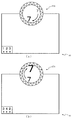
次いで、図33から図39を参照して、回転動作ユニット600について説明する。図33は、回転動作ユニット600の正面斜視図である。
Next, the
図33に示すように、回転動作ユニット600は、球体液晶装置670に対し、その周囲を取り囲むように正面視円環状の第1回転体650が配置されると共に、その第1回転体650の背面側に正面視円環状の第2回転体660が同心に配置され、本実施形態では、これら第1回転体650及び第2回転体660が異なる回転速度で且つ互いに逆方向へ回転される。
As shown in FIG. 33, the
ここで、複数の回転体を互いに離れた位置に配置される従来品では、それら複数の回転体の回転を関連づけて遊技者に認識させることが困難であった。即ち、従来品は、各回転体が他の回転体と関わり合わずに、それぞれが独立して回転される形態であり、そのため、複数の回転体を回転させることによる演出の効果を十分に発揮させることができなかった。 Here, in the conventional product in which a plurality of rotating bodies are arranged at positions separated from each other, it is difficult to make the player recognize the rotations of the plurality of rotating bodies in association with each other. That is, the conventional product is configured such that each rotating body is independently rotated without being associated with other rotating bodies, and therefore, the effect of the effect by rotating a plurality of rotating bodies is sufficiently exhibited. I couldn't let it go.
これに対し、本実施形態における回転動作ユニット600によれば、球体液晶装置670を中心として、第1回転体650と第2回転体660とが同心に配置され、これら二つの回転体が異なる回転態様(回転速度および回転方向を互いに異ならせる態様)で回転されるので、これらの回転を関連づけて遊技者に認識させやすくでき、複数の回転体を回転させることによる演出の効果を発揮することができる。かかる回転動作ユニット600の詳細構成について、以下に説明する。
On the other hand, according to the
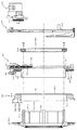
図34は、回転動作ユニット600の分解正面斜視図であり、図35は、回転動作ユニット600の分解背面斜視図である。また、図36は、回転動作ユニット600の縦断面図である。なお、図35及び図36では、球体液晶装置670の図示が省略される。また、図36に示す断面は、第1回転体650及び第2回転体660の回転中心を含む平面により切断された回転動作ユニット600の断面に対応する。
FIG. 34 is an exploded front perspective view of the
図34から図36に示すように、回転動作ユニット600は、その骨格をなす表ケース体610及び背面ケース体620と、背面ケース体620の背面側に配設される駆動モータ630と、その駆動モータ630の回転駆動力を伝達する伝達手段としての複数の歯車(第1〜第5収納ギヤ641〜645及び正面ギヤ646)と、それら複数の歯車を介して駆動モータ630の回転駆動力が伝達されて回転される第1回転体650及び第2回転体660と、それら第1回転体650及び第2回転体660の内周側に配設される球体液晶装置670と、正面ケース体610の正面に配設される発光装置680と、を主に備えて構成される。
As shown in FIGS. 34 to 36, the
正面ケース体610及び背面ケース体620は、樹脂材料から平板状に形成され、所定間隔を隔てた状態で対向配置されると共に、ねじ(図示せず)によって互いが締結固定されることで、その対向面間に内部空間が形成される収容部材として構成される。これら正面ケース体610及び背面ケース体620の内部空間(対向面間)には、第1〜第5収納ギヤ641〜645と、第1回転体650の収納フランジ部653とがそれぞれ収納される。
The
正面ケース体610及び背面ケース体620には、正面視円形の開口611,621がそれぞれ開口形成され、これら開口611,621は、組立状態において同心に配設される。正面ケース体610の正面側には、開口611,621と同心となる位置に、筒状の筒状部612が正面(前方)へ向けて突設される。正面ケース体610は、開口611及び筒状部612の内径寸法が同一の寸法に設定され、それら開口611及び筒状部612の内周側には、第1回転体610の本体部651が回転可能に支持される。また、筒状部612の外周側には、第2回転体620が回転可能に支持される。
The
このように、正面ケース体610の筒状部611の内周面および外周面により、第1回転体650(本体部651)及び第2回転体660を回転可能に支持することで、これら第1回転体650及び第2回転体660の配設位置を、それぞれ正面ケース体610を基準として規定できる。よって、後述するように、第1回転体650(収納フランジ部653)及び第2回転体660のそれぞれの外周面に刻設された歯車(第1及び第2外周ギヤ653a,661a)と、正面ケース体610に配設される第2収容ギヤ642及び正面ギヤ646との間の位置関係を、正面ケース体610を基準として規定できる。その結果、両回転体650,660の両外周ギヤ653a,661aと第2収容ギヤ642及び正面ギヤ646との歯合状態を安定化させることができるので、歯車の偏摩耗を抑制できると共に駆動抵抗の抑制を図ることができる。
As described above, the first rotating body 650 (main body portion 651) and the second
駆動モータ630は、その駆動軸にピニオンギヤ631が取着され、背面ケース体620の背面に装着されることで、ピニオンギヤ631を、伝達手段を構成する複数の歯車のうちの第1収納ギヤ641に歯合させる。よって、駆動モータ420の回転駆動力を、ピニオンギヤ431を介して、伝達手段(複数の歯車)へ伝達することができ、その結果、後述するように、第1回転体650及び第2回転体660をそれぞれ回転させることができる。
The
第1〜第5収納ギヤ641〜645及び正面ギヤ646は、上述したように、駆動モータ630の回転駆動力を第1回転体650及び第2回転体660へ伝達するための歯車群であり、歯が回転軸と平行に外周面に刻設される平歯車としてそれぞれ形成される。第1〜第5収納ギヤ641〜645は、正面ケース体610の背面側に回転可能に軸支され、直列に連結(歯合)し合うことで、第1収納ギヤ641を先頭とし第5収納ギヤ645を後尾とする1のギヤトレーン(歯車列)を形成する。
As described above, the first to fifth storage gears 641 to 645 and the
正面ギヤ646は、第5収納ギヤ645に同期回転可能な状態で、正面ケース体610の正面側に回転可能に軸支される。即ち、正面ギヤ646及び第5収納ギヤ645は、正面ケース体610を貫通して配設される回転軸の一端および他端にそれぞれ固着され、これら両ギヤ645,646と回転軸とが一体となって回転される。
The
このように構成される歯車群によれば、駆動モータ630が回転駆動されると、その回転駆動力がピニオンギヤ631を介して第1収容ギヤ641に伝達され、第1収容ギヤ641が回転される。第1収容ギヤ641の回転は、ギヤトレーン(歯車列)の作用により第5収容ギヤ645まで伝達され、かかる第5収容ギヤ645が回転されることで、正面ギヤ646が回転される。
According to the gear group configured in this manner, when the
ここで、後述するように、第2収容ギヤ642には、第1回転体650(収納フランジ部653)の第1外周ギヤ653aが、正面ギヤ646には、第2回転体660の第2外周ギヤ661aが、それぞれ歯合されるので、駆動モータ630の回転駆動に伴い、第1回転体650及び第2回転体660をそれぞれ回転させることができる。即ち、1の駆動モータ630の回転駆動により、2の回転体(第1回転体650及び第2回転体660)を同時に回転させることができる。
Here, as will be described later, the first outer
この場合、本実施形態では、第2収容ギヤ642と第5収容ギヤ645との間には、偶数個のギヤ(第3及び第4収容ギヤ643,644)が介在される。よって、第5収容ギヤ645に同期回転される正面ギヤ646と第2収容ギヤ642との間の回転速度を異なるせることができるだけでなく、第2収容ギヤ642と正面ギヤ646との間の回転方向を異ならせることもできる。その結果、後述するように、第1回転体650と第2回転体660との間の回転速度および回転方向をそれぞれ異ならせることができる。
In this case, in the present embodiment, an even number of gears (third and fourth housing gears 643 and 644) are interposed between the
また、本実施形態では、正面ケース体610の背面側に第2収納ギヤ642を含む歯車列が、正面ケースチア610の正面側に正面ギヤが、それぞれ配設され、正面ケース体610の正面側および背面側において、それぞれ第2収納ギヤ642及び正面ギヤ646を、第1回転体650の第1外周ギヤ653a及び第2回転体660の第2外周ギヤ651aに歯合させる。よって、例えば、正面ケース体610の正面側に第2収納ギヤ642及び正面ギヤ646の両者を配置し、これら両ギヤ642,646を、第1回転体650及び第2回転体660にそれぞれ歯合させる構造と比較して、駆動モータ630の回転駆動力を第1回転体650及び第2回転体660へ伝達する伝達構造だけでなく、第1回転体650及び第2回転体660自体の構造も簡素化できる。
Further, in the present embodiment, a gear train including the
更に、歯車列とその歯車列のうちの第2収納ギヤ642が歯合される第1回転体650の収納フランジ部653とが、正面ケース体610の背面側に配設されることで、回転動作ユニット600を正面視する遊技者に対して、歯車列および収納フランジ部653とを正面ケース体610により遮蔽することができる。即ち、歯車列および収納フランジ部653を視認不能に遮蔽するための遮蔽構造を、別部材を設けることを必要とせず、背面ケース体610を利用して簡素に形成することができる。
Further, the gear train and the
第1回転体650は、球体液晶装置670の周囲を回転することで演出を行うための演出部材であり(図33参照)、本体部651と、その本体部651の軸方向一側に一体に形成される正面演出部652と、本体部651の軸方向他側(軸方向端面)にねじにより締結固定される収納フランジ部653と、を主に備える。
The
本体部651は、樹脂材料から円筒状に形成される部位であり、正面ケース体610における開口611及び筒状部612の内周側に挿通される。即ち、第1回転体650は、本体部651を回転軸として、正面ケース体610(開口611及び筒状部612)に回転可能に保持される。ここで、本体部651の詳細構成について、図37を参照して説明する。
The
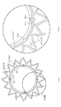
図37(a)は、本体部651の背面図であり、図37(b)は、図37(a)のXXXVII部分を拡大して示す本体部651の部分拡大背面図である。なお、図37(b)では、理解を容易とするために、第1突出部651a及び第2突出部651bの直径が実際よりも拡大して模式的に図示されると共に、第1突出部651a及び第2突出部651bの各頂部がそれぞれ内接される仮想の円である仮想円ISが二点鎖線を用いて図示される。
FIG. 37 (a) is a rear view of the
図37(a)及び図37(b)に示すように、本体部651には、第1突出部651a及び第2突出部651bが形成されると共に、第2突出部651bに対応する位置には、オフセット部651cが形成される。
As shown in FIGS. 37 (a) and 37 (b), the
第1突出部651a及び第2突出部651bは、本体部651の外周面および内周面のそれぞれから突出して形成されると共に本体部651の軸方向(図37(a)紙面垂直方向)に沿いつつ本体部651の全長にわたって延設される部位であり(図35参照)、周方向等間隔となる複数箇所(本実施形態では合計8箇所)であって、第1突出部651aと第2突出部651bとが周方向に交互に点在して配置されて形成される。
The first projecting
即ち、第1突出部651aは、本体部561の板厚寸法よりも大きな直径寸法を有する断面円形の円柱状体を本体部651と軸方向を一致させた姿勢で本体部651内に埋設し、この埋設された円柱状体のうちの本体部651の外周面および内周面から突出した部分(円柱状体の一部)により形成される。第2突出部651bについても、本体部651に埋設される円柱状体の直径が第1突出部651aよりも大径とされる点を除き、第1突出部651aと同様である。
That is, the first projecting
このように、本体部651の外周面および内周面から突出される第1突出部651a及び第2突出部651bが軸方向に沿って本体部651の全長にわたって延設されることで、本体部651の剛性を高めることができる。
As described above, the first projecting
なお、第2突出部651bは、本体部651の軸方向端面(図37(b)紙面手前側面)から更に軸方向に沿って延設される。よって、後述するように、本体部651に収納フランジ部653がねじにより締結固定される際には、第2突出部651bの軸方向への延設部分が、収納フランジ部653の前面に凹設される凹部に内嵌されることで、本体部651及び収納フランジ部653を相対回転不能に強固に結合させることができる(図36参照)。
The second projecting
オフセット部651cは、本体部651における第2突出部651b形成部分の近傍を、板厚寸法を保持しつつ内周側にオフセットさせた部分であり、第2突出部651bの直径の略3倍の範囲(周方向)にわたって形成される。即ち、オフセット部651cは、図37(b)に示す本体部651の軸方向視において、本体部651と同心の円弧状に湾曲される。このように本体部651にオフセット部651cが形成されることで、後述するように第2突出部651bの軸心を軸心側にオフセットさせて位置させることができると共に、本体部651全体としての剛性を高めることができる。
The offset
複数(本実施形態では4個)の第1突出部651aは、本体部651の外周面からの突出量が互いに同一に設定され、複数(本実施形態では4個)の第2突出部652bは、本体部651の外周面からの突出量が互いに同一に設定されると共に、オフセット部651cによるオフセットにより第1突出部651aの突出量とも同一とされる。複数(本実施形態では8個)の第1突出部651a及び第2突出部652bは、本体部651の外周面からの突出量がそれぞれ同一に設定される。これにより、図37(b)に示すように、第1突出部651a及び第2突出部652bの各頂部が内接する仮想円ISを、本体部651の外周側に同心に設定することができる。この場合、仮想円ISの直径寸法は、正面ケース体610における開口611及び筒状部612の内径寸法と同等の寸法または若干大きな寸法に設定される。
The plurality of (four in this embodiment)
よって、正面ケース体610の開口611及び筒状部612の内周側に第1回転体650の本体部651が挿通された状態では、それらの接触領域を第1突出部651a及び第2突出部651bの各頂部に限定できるので、接触抵抗を抑制して、開口611及び筒状部612の内周側で本体部651をスムーズに回転させることができる。
Therefore, in the state in which the
特に、第1突出部651a及び第2突出部651bは、軸方向視円弧状(詳細には、本体部651の軸方向に直交する平面で切断した断面の形状が外方へ凸となる円弧状)に湾曲されるので、接触面積を抑制できるだけでなく、正面ケース体610の開口611及び筒状部612の内周面に対して第1及び第2突出部651a,651bの頂部を滑らかに接触させることができるので、寸法公差に起因してがたつきを有する場合であっても、開口611及び筒状部612の内周側で本体部651をよりスムーズに回転させることができる。
In particular, the first projecting
第1突出部651a及び第2突出部651bは、上述したように、本体部651の外周面から突出されるだけでなく、本体部651の内周面からも突出される。これにより、本体部651を樹脂金型により成形する際には、本体部651の形状を外周面側および内周面側において均一化(対称形状化)して、その成形性を確保できる。
As described above, the first projecting
特に、本実施形態では、図37(b)に示す本体部651の軸方向視において、第1突出部651aは、本体部651の外周面から突出して形成される部分の突出寸法と本体部651の内周面から突出して形成される部分の突出寸法とが同一とされる。同様に、第2突出部651aは、オフセット部651cの外周面から突出して形成される部分の突出寸法とオフセット部651cの内周面から突出して形成される部分の突出寸法とが同一とされる。よって、本体部651の外周面側および内周面側における形状をより均一化(対称形状化)して、その成形性を更に確保できる。
In particular, in the present embodiment, the first projecting
また、第2突出部651bには、その軸方向に沿って穿設される断面円形の孔が全長にわたって穿設される(図36参照)。これにより、第1突出部651aに比較して大径とされる第2突出部651bにおける肉厚寸法を他の部分(本体部651やオフセット部651c、第1突出部651aなど)と均一化でき、その結果、本体部651の成形性を確保できる。
Further, the
この場合、第2突出部651bに穿設される孔の内周面にはめねじが刻設され、収納フランジ部653を締結固定するためのねじが螺合可能とされる(図36参照)。このように、ねじを締結するためのねじ締結部を、比較的大径に形成される第2突出部651bが担うことで、ねじ締結部の強度を確保できる。特に、第2突出部651bはオフセット部651cに形成される部位であり、本体部651の剛性が強化されているので、本体部651と収納フランジ部653との連結部分を第2突出部651bが担うことで、両者を強固に連結できると共に、耐久性の向上を図ることができる。
In this case, a female screw is formed on the inner peripheral surface of the hole formed in the second projecting
図34から図36に戻って説明する。正面演出部652は、遊技者に演出部分として視認される部位であり、本体部651の外周面から径方向外方へフランジ状に張り出して形成される。正面演出部652の正面(前面、外観形成面)には、メッキが施され、光沢のある金属を模した外観が正面演出部652に付与される。なお、正面演出部652は、光透過性の樹脂材料からなるが、メッキが施されることで、正面演出部652を透かして発光装置680(発光素子681)が遊技者に視認されることを回避できる。
Referring back to FIG. 34 to FIG. The
正面演出部652の正面視形状は、不定形状の山(第2部分)と谷(第1部分)とが周方向に沿って繰り返される鋸刃形状に形成され、本実施形態では、16個の山(谷)が周方向不等間隔(不等ピッチ)で配設される。後述するように、第1回転体650が回転されると、正面演出部652の山と谷とが発光装置680の発光素子681の正面側(前方)を順に通過することで、遊技者に発光素子681を断続的かつ選択的に視認させることができる(図39参照)。
The
収納フランジ部653は、正面ケース体610及び背面ケース体620の内部空間(対向面間)に収納される部位であり、正面視円環形状に形成されると共に、正面ケース体610の筒状部612に挿通された本体部651の軸方向端面に開口611を介して締結固定される。詳細には、収納フランジ部653に挿通されたねじを、上述したように、本体部651の第2突出部651bに螺合させることで、本体部651に収納フランジ部653が締結固定される。
The
収納フランジ部653は、その厚み寸法が、正面ケース体610及び背面ケース体620の対向面間隔と同等の寸法または若干小さな寸法に設定されると共に、外径寸法が、正面ケース体610及び背面ケース体620における開口611,621の内径寸法よりも大きな寸法に設定される。よって、第1回転体650は、収納フランジ部653の正面または背面を正面ケース体610の背面または背面ケース体620の正面に当接させることで、その第1回転体650の軸方向位置を規定できる。
The
収納フランジ部653の外周面には、第1外周ギヤ653aが刻設され、この第1外周ギヤ653aには、正面ケース体610の背面に配設される上述した歯車列のうちの第2収納ギヤ642が歯合される。よって、駆動モータ630の回転駆動力により歯車列が回転されると、その回転が、第2収納ギヤ642及び第1外周ギヤ653aを介して収納フランジ部653に伝達され、第1回転体650が回転される。
A first outer
このように、第1回転体650は、収納フランジ部653の外周面に第1外周ギヤ653aを刻設し、正面ケース体610の開口511に周縁に沿って配設された歯車列のうちの第2収納ギヤ642を第1外周ギヤ653aに歯合させるので、駆動モータ630の回転駆動力を第1回転体650へ伝達するための伝達構造を簡素化できる。特に、第1回転体650は、筒状に形成され、その内周側に後述する球体液晶装置670の被投射面部671が配設されるため、内周面側にスペースを確保することが困難となる。そのため、第1回転体650の外周側に上述した伝達構造を配設できることが有効となる。
As described above, the first
また、上述したように、第1回転体650(本体部651)は、正面ケース体610の筒状部611の内周面に回転可能に支持されるので、かかる第1回転体650の配設位置を、正面ケース体610を基準として規定できる。よって、第1回転体650(収納フランジ部653)の外周面に刻設された歯車(第1外周ギヤ653a)と、正面ケース体610に配設される第2収容ギヤ642との間の位置関係を、正面ケース体610を基準として規定できる。その結果、第1回転体650の第1外周ギヤ653aと第2収容ギヤ642との歯合状態を安定化させることができるので、歯車の偏摩耗を抑制できると共に駆動抵抗の抑制を図ることができる。
Further, as described above, the first rotating body 650 (main body portion 651) is rotatably supported on the inner peripheral surface of the
第2回転体660は、第1回転体650の背面側で回転することで演出を行うための演出部材であり(図33参照)、光透過性の樹脂材料から円筒状に形成される本体部661と、その本体部661の軸方向端面に一体に形成される正面演出部662と、を主に備える。
The
本体部661は、その内径寸法が正面ケース体610における筒状部612の外径寸法と同等の寸法または若干大きな寸法に設定され、筒状部612の外周側に外嵌されることで(即ち、本体部661の内周側に筒状部612を挿通させることで)、正面ケース体610(筒状部612)に回転可能に保持される。
The
本体部661の外周面には、第2外周ギヤ661aが刻設され、この第2外周ギヤ661aには、正面ケース体610の正面に配設される上述した正面ギヤ646が歯合される。よって、駆動モータ630の回転駆動力により上述した歯車列および正面ギヤ646が回転されると、その回転が、正面ギヤ646及び第2外周ギヤ661aを介して本体部661に伝達され、第2回転体660が回転される。
A second outer
このように、第2回転体660は、その外周面に第2外周ギヤ661aを刻設し、正面ケース体610の正面に配設された正面ギヤ646を第2外周ギヤ661aに歯合させるので、駆動モータ630の回転駆動力を第2回転体660へ伝達するための伝達構造を簡素化できる。特に、第2回転体650は、筒状に形成され、正面ケース体610の筒状部612に外嵌されることで回転可能の保持される構造であるため、内周面側にスペースを確保することが困難となる。そのため、第2回転体660の外周側に上述した伝達構造を配設できることが有効となる。
Thus, the second
また、上述したように、第2回転体660は、正面ケース体610の筒状部611の外周面に回転可能に支持されるので、かかる第2回転体660の配設位置を、正面ケース体610を基準として規定できる。よって、第2回転体660の外周面に刻設された歯車(第2外周ギヤ661a)と、正面ケース体610に配設される正面ギヤ646との間の位置関係を、正面ケース体610を基準として規定できる。その結果、第2回転体660の第2外周ギヤ661aと正面ギヤ646との歯合状態を安定化させることができるので、歯車の偏摩耗を抑制できると共に駆動抵抗の抑制を図ることができる。
Further, as described above, since the second
本体部661は、その軸方向寸法が、正面ケース体610の正面と第1回転体650の正面演出部652の背面との対向間隔と同等の寸法または若干小さい寸法に設定される。よって、第2回転体660は、本体部661の軸方向一側の端面または軸方向他側の端面を第1回転体650の正面演出部652の背面または正面ケース体610の正面に当接させることで、その第2回転体650の軸方向位置を規定できる。
The
なお、本体部661は、その軸方向一側の端面および軸方向他側の端面に正面凸条661b及び背面凸条661cがそれぞれ突設される。正面凸条661bは正面視円環形状に形成されると共に、背面凸条661cは正面視円環形状を複数箇所で分断した形状に形成される。これにより、第1回転体660を回転させる際には、本体部661と正面ケース610及び第2回転体650(正面演出部652)との間の摩擦抵抗を低減して、駆動モータ630の負荷を抑制できる。
A front ridge 661 b and a
正面演出部662は、第1回転体650における正面演出部652の背面側に位置し、その演出部652と共に遊技者に演出部分として視認される部位であり、本体部661の外周面から径方向外方へフランジ状に張り出して形成される。正面演出部662は、不定形状の山と谷とが周方向に沿って繰り返される鋸刃形状に形成される外周側部分662aと、その外周側部分662aの内周側における正面視円環形状の部分である内周側部分662bとを備える。
The
正面演出部662の正面(前面、外観形成面)には、第1回転体650の正面演出部652の場合と同様に、メッキが施される。但し、上述した第1回転体650では、正面演出部652の全面(全範囲)にメッキが施されたが、第2回転体650では、正面演出部662のうちの外周側部分662aのみにメッキが施され、内周側部分662bにはメッキは施されない。
Plating is applied to the front surface (front surface, appearance forming surface) of the
よって、後述するように、第1回転体650における正面演出部652の山(第2部分)と谷(第1部分)とを発光装置680における発光素子681の正面側(前方)で順に通過させて、発光素子681を遊技者に断続的かつ選択的に視認させる際には、かかる発光素子681を、正面演出部662の内周側部分662b(即ち、メッキが施されていない部分)を透かして、遊技者に視認させることが可能とされる(図39参照)。
Therefore, as will be described later, a mountain (second portion) and a valley (first portion) of the
球体液晶装置670は、光透過性材料から球殻として形成される被投射面部671と、その被投射面部671の球殻の内面に映像を投射する投射装置が内部に収納されたケース体672と、を主に備え、投射装置から投射され被投射面部671の外面に透過された映像を遊技者に視認させる。組立状態では、ケース体672が背面ケース体620の背面に締結固定され、被投射面部671が、その球殻の略半分を第1回転体650の正面演出部652の正面よりも前方へ突出させた姿勢で、第1回転体650の内周側に配設される(図33参照)。
The spherical
発光装置680は、正面ケースの610の筒状部612に外嵌される正面視円環形状のケース体681と、そのケース体681に収納される回路基板と、その回路基板の正面(前面)側に配設(搭載)される複数(本実施形態では12個)の発光素子682と、を主に備え、組み立て状態において、第1回転体650及び第2回転体660の正面演出部652,662の背面側に配設される。
The light-emitting
ケース体681の正面(前面)には、発光素子682よりも大きな外形を有する開口部が周方向等間隔となる12箇所に開口形成され、それら各開口部の開口位置に対応して各発光素子682が回路基板に搭載される。即ち、発光装置680は、その正面視において、ケース体681の開口部から発光素子682が露出され、発光素子682から発光された光をケース体681の開口部を介して正面側(第1回転体650及び第2回転体660の正面演出部652,662)へ向けて照射可能とされる。
On the front surface (front surface) of the
発光装置680の正面(前面)側には、上述したように、第1回転体650及び第2回転体660の正面演出部652,662が配設され、第1回転体650の正面演出部652が回転されることで、発光素子682による発光を断続的かつ選択的に遊技者に視認させることが可能とされる。ここで、発光素子682の発光を断続的かつ選択的に遊技者に視認させる構造について、図38及び図39を参照して説明する。
As described above, the
図38は、回転動作ユニット600の正面図であり、図38(a)及び図38(b)では、第1回転体650が互いに異なる回転位置に配置された状態が図示される。図39(a)は、図38(a)のXXXIXa−XXXIXa線における回転動作ユニット600の断面図であり、図39(b)は、図38(b)のXXXIXb−XXXIXb線における回転動作ユニット600の断面図である。
FIG. 38 is a front view of the
なお、図38では、第1回転体650の正面演出部652と発光装置680の発光素子682との間の位相関係を明確とするために、回転動作ユニット600のうちの第1回転体650及び発光装置680のみが図示され、図39では、第1回転体650及び第2回転体660の正面演出部652,662と発光装置680の発光素子682との径方向位置の関係を明確とするために、図38に示す第1回転体650及び発光装置680に第2回転体660が追加された分解状態が模式的に図示される。
38, in order to clarify the phase relationship between the
図38及び図39に示すように、第1回転体650における正面演出部652の正面視形状が、不定形状の山(第2部分)と谷(第1部分)とが周方向に沿って繰り返される鋸刃形状に形成されるところ、発光装置680における発光素子682の配設位置は、正面演出部652における谷底よりも径方向外側(図39(a)上側)であって正面演出部652における山頂よりも径方向内側(図39(a)下側)となる径方向位置(図39(a)上下方向位置)に設定される。
As shown in FIGS. 38 and 39, the front view shape of the
この場合、第2回転体660の正面演出部662における内周側部分662bには、上述したように、正面(前面)にメッキが施されず、光を透過可能に形成されるところ、かかる内周側部分662bの形成範囲(図39において二点鎖線で示す範囲)が、第1回転体650の正面演出部652における谷底と、発光装置680の発光素子682とを含む範囲に設定される。即ち、正面視において、第1回転体650の正面演出部652における谷の部分から、第2回転体660の正面演出部662における内周側部分662bを介して(即ち、透過させて)、発光装置680の発光素子682を遊技者に視認させることができる。
In this case, as described above, the inner (peripheral)
また、第2回転体660の正面演出部662における外周側部分662aには、上述したように、正面(前面)にメッキが施され、光沢のある金属を模した外観が付与されるところ、かかる外周側部分662aが、第1回転体650の正面演出部652の背面側に対向して配設される。即ち、正面視において、第1回転体650の正面演出部652における谷の部分から、第2回転体660の正面演出部662における外周側部分662aを遊技者に視認させることができる。
In addition, as described above, the outer
このように、回転動作ユニット600によれば、第1回転体650の正面演出部652には、正面視において発光装置680の発光素子682に重なる領域に、山と谷とが周方向交互に形成されるので、第1回転体650の回転に伴い、その正面演出部652の山と谷とが発光素子682の前方を交互に通過することで、発光素子682の発光を、第2回転体660の正面演出部682における内周側部分662bを介して、遊技者に断続的に視認させることができる。これにより、球体液晶装置670を中心とし、その周囲において、複数の回転体(第1回転体650及び第2回転体660)をそれぞれ回転させる演出を効果的に行うことができる。
As described above, according to the
また、第2回転体660の正面演出部662における外周側部分662aには、メッキが施され、光沢のある金属を模した外観が付与されるところ、その外周側部分662aの正面(前面)側には、第1回転体650の正面演出部652が配設される。よって、上述したように、第1回転体650と第2回転体660とが互いに逆方向へ回転される際には、第1回転体650の正面演出部652における谷の部分を介して、第2回転体660の正面演出部652における外周側部分662aが、第1回転体650の正面演出部652とは逆方向へ回転される態様を遊技者に視認させることができる。
In addition, the outer
即ち、回転動作ユニット600によれば、第1回転体650を正面視する遊技者に対し、正面演出部652の山谷形状における谷底側では、発光装置680の発光素子682を断続的に視認させると共に、正面演出部652の山谷形状における山頂側では、第2回転体660の正面演出部662(外周側部分662a)が第1回転体650の正面演出部652(山谷形状)と逆方向へ回転される態様を視認させることができる。これにより、第1回転体650の回転と第2回転体660の回転とを関連付けて遊技者に認識させやすくでき、その結果、複数の回転体(第1回転体650及び第2回転体660)をそれぞれ回転させる演出を効果的に行うことができる。
That is, according to the
更に、回転演出ユニット600によれば、上述したように、第1回転体650の正面演出部652における谷が周方向16箇所に形成される一方で、発光装置680の発光素子682が周方向12箇所に配設されるので、それら12箇所に配設された発光素子682のうちから遊技者に特定の発光素子682のみを選択的に視認させることができる。
Further, according to the
即ち、正面演出部652における谷の周方向間隔と、発光素子682の周方向間隔とが異なる間隔とされることで、例えば、図38(a)に示す状態では、上下左右の4箇所に配設された発光素子682が視認可能とされる一方で、図38(a)に示す状態から第1回転体650(正面演出部652)が所定の回転角度だけ回転されると、図38(b)に示すように、異なる発光素子682が選択され、右上、右下、左下および左上の4箇所に配設された発光素子682が視認可能とされる。
That is, the circumferential spacing of the valleys in the
これにより、発光装置680の発光素子682を断続的に視認させるだけでなく、視認される発光素子682の位置を周方向へ変更することができるので、複数の回転体(第1回転体650及び第2回転体660)をそれぞれ回転させる演出をより効果的に行うことができる。
Thereby, not only can the
図34から図36に戻って、回転動作ユニット600の全体構造について説明する。上述したように、正面ケース体610に開口611及び筒状部612が形成され、第1回転体650が本体部651及び正面演出部652に対して収納フランジ部653が別体に形成される。よって、正面ケース体610の筒状部612の外周側に第2回転体660を装着し、正面ケース体610の筒状部612の内周側に第1回転体650の本体部651を挿通すると共に、その挿通した本体部651に収納フランジ部653を締結固定した後、正面ケース体610に背面ケース体620を締結固定することで、正面ケース体610及び背面ケース体620に第1回転体650及び第2回転体660を回転可能な状態で保持させることができる。
Returning to FIG. 34 to FIG. 36, the overall structure of the
即ち、第1回転体650は、その本体部651が正面ケース体610の開口611及び筒状部612に挿通されることで、かかる正面ケース体610に回転可能に軸支される。この場合、第1回転体650の収納フランジ部653が正面ケース体610の背面および背面ケース体620の正面にそれぞれ当接可能とされ、これにより、両ケース体610,620に対する第1回転体650の正面側(前方)および背面側(後方)への変位を規制できる。
That is, the first
同時に、第2回転体660は、正面ケース体610の筒状部612に外嵌されることで、かかる正面ケース体610に回転可能に軸支される。この場合、第2回転体660(正面凸条661b及び背面凸条662c)が、第1回転体650の正面演出部652の背面および発光装置680のケース体681の正面にそれぞれ当接され、これにより、両ケース体610,620に対する第2回転体660の正面側(前方)および背面側(後方)への変位を規制できる。
At the same time, the second
このように、回転動作ユニット600によれば、複数の回転体(第1回転体650及び第2回転体660)を回転可能な状態で保持可能としつつ、回転体(第1回転体650)自身が第2回転体660の変位を規制する部位を兼用するため、その分、構造の簡素化を図ることができる。また、複数の回転体(第1回転体650及び第2回転体660)を回転可能な状態で保持可能とする保持構造を、第1回転体650の本体部651に収納フランジ部653を締結固定するのみで形成できるので、組み立て工程を簡素化できる。その結果、製品コストの削減を図ることができる。
Thus, according to the
また、回転動作ユニット600によれば、第1回転体650が筒状に形成されると共に、背面ケース体620に開口621が形成されるので、正面ケース体610及び背面ケース体620に複数の回転体(第1回転体650及び第2回転体660)を回転可能な状態で保持させた後は、背面ケース体620の背面側から球体液晶装置670を装着して締結固定するだけで、回転動作ユニット600の組み立てを完了することができる(図33参照)。即ち、各ケース体5610,620及び各回転体650,660の組立品に対して、球体液晶装置670を別工程にて後付けすることができる。よって、この点も、組み立て工程を簡素化して、製品コストを削減することに寄与できる。
Further, according to the
以上、上記実施形態に基づき本発明を説明したが、本発明は上記形態に何ら限定されるものではなく、本発明の趣旨を逸脱しない範囲内で種々の変形改良が可能であることは容易に推察できるものである。 Although the present invention has been described based on the above embodiment, the present invention is not limited to the above embodiment, and various modifications can be easily made without departing from the spirit of the present invention. It can be guessed.
上記実施形態における突出動作ユニット400では、基側変位部材440に対して相対変位部材450がスライド変位可能に配設される場合を説明したが、必ずしもこれに限られるものではなく、基側変位部材440に対して相対変位部材450が回転可能に配設されるものであって良い。即ち、第1動作を、上記実施形態の場合と同様に、基側変位部材440を退避位置(図13参照)及び回転位置(図14参照)の間で回転させるものとし、第2動作を、相対変位部材450を基側変位部材440に対して基準位置(図14参照)及び張出位置(図15参照)の間で回転させる構成を採用しても良い。
In the
この構成によっても、退避位置にある基側変位部材450が第1動作により回転位置へ配置されると共に、基準位置にある相対変位部材450が第2動作により張出位置へ配置されることで、両変位部材440,450全体を遊技者に十分に視認させ、その演出効果を十分に発揮させることができる一方、張出位置にある相対変位部材450が第2動作により基準位置に回転されると共に、回転位置にある基側変位部材440が第1動作により退避位置へ配置されることで、両変位部材440,450全体を小さくして、変位部材を収容するために必要とされるスペースを抑制できる。
Even with this configuration, the base
上記実施形態における突出動作ユニット400では、基側変位部材440が退避位置に配置された状態において(図17(b)参照)、基側変位部材450の先端側が相対変位部材450の先端側よりも装飾部材480側(図17(b)上側)へ突出される場合を説明したが、必ずしもこれに限られるものではなく、これとは逆に、相対変位部材450の先端側が基側変位部材450の先端側よりも装飾部材480側(図17(b)上側)へ突出される構成を採用しても良い。
In the protruding
この構成によっても、両変位部材440,450の回転軌跡を装飾部材480と交差させ、その交差の際に装飾部材480を透過させて両変位部材440,450を視認させることができるので、両変位部材440,450を変位させることによる演出効果を高めることができる。更に、この構成によれば、相対変位部材450を張り出させる際には(図15参照)、正面(前方)に位置する装飾部454の面積をより拡大することができ、迫力のより一層の向上を図ることができる。
Also with this configuration, the rotational trajectories of both
上記実施形態における複合動作ユニット500では、被駆動部材550の接続溝552aが長穴形状に形成されることで、被駆動部材550(接続溝552a)に従動部材560(接続軸561b)が回転可能かつスライド変位可能な状態で接続される場合を説明したが、必ずしもこれに限られるものではなく、接続溝552aが円形状に形成されることで、被駆動部材550(接続溝552a)に対する従動部材560(接続軸561b)のスライド変位が不能とされる構成(即ち、回転のみが許容される構成)を採用しても良い。この構成によっても、被駆動部材550の変位に伴って従動部材560を相対変位させる際に、被駆動部材550に対する従動部材560の相対的な角度を変化させることができるので、従動部材560の軌道に変化を付与して、演出効果を高めることができる。
In the combined
なお、この場合には、第1案内溝513及び第1ピン561aにより構成される変位規定手段を、従動部材560に接続軸561bと同心に配設される歯車とその歯車に歯合されると共に被駆動部材550の駆動軸551aを中心とする円弧に沿って形成され正面ケース体510又は背面ケース体520に配設される湾曲したラックギヤとにより構成しても良い。これにより、被駆動部材550の変位に伴って従動部材560を相対変位させる際に、歯車がラックギヤを転動することで、被駆動部材550に対する従動部材560の相対的な角度を変化させることができる。
In this case, the displacement defining means constituted by the
上記実施形態における複合動作ユニット500では、第1案内溝513及び第2案内溝523が正面ケース体510及び背面ケース体520に形成されると共に、これら両案内溝513,523にそれぞれ挿通される第1ピン561a及び接続軸561bが従動部材560に形成される場合を説明したが、必ずしもこれに限られるものではなく、これとは逆に、第1案内溝513及び第2案内溝523を従動部材560に設けると共に、それら両案内溝513,523に挿通される部位(第1ピン561a及び接続軸561bに相当する部材)を正面ケース体510及び(又は)背面ケース体520に設ける構成を採用しても良い。この構成によっても、被駆動部材550の変位に伴って、直線運動と回転運動とを組み合わせた運動を従動部材560に行わせることができるので、かかる従動部材560の軌道に変化を付与して、演出効果を高めることができる。
In the combined
上記実施形態における複合動作ユニット500では、第1案内溝513が正面ケース体510に穿設(開口形成)される場合を説明したが、必ずしもこれに限られるものではなく、かかる第1案内溝513が例えば断面コ字状の凹溝として形成されても良い。即ち、第1案内溝513は、その延設方向に沿って第1ピン561aを案内可能な形状であれば足りる趣旨である。
In the combined
上記実施形態における複合動作ユニット500では、第1案内溝513及び第2案内溝523が湾曲して延設される一方、接続溝551aが直線状に延設される場合を説明したが、必ずしもこれに限られるものではなく、これとは逆に、第1案内溝513及び第2案内溝523が直線状に延設される一方、接続溝551aが湾曲して延設される構成を採用しても良い。特に、第1案内溝513及び第2案内溝523については、曲率半径が一定の円弧形状に設定される場合を説明したが、これに限られるものではなく、複数の曲率半径の円弧形状を組み合わせた形状(例えば、S字状など)を採用することは当然可能である。これにより、従動部材560の軌道をより複雑に変化させることができるので、演出効果を高めることができる。
In the combined
具体的には、例えば、第1案内溝513又は第2案内溝523を円弧形状に設定する場合、その円弧形状を、被駆動部材550が軸部553,554を中心とする回転方向の回転始端または終端およびその近傍に配置される状態では、半径を基準値よりも大きくする(曲率を小さくする)ことが好ましい。即ち、第1案内溝513又は第2案内溝523における始端およびその近傍の第1範囲または終端およびその近傍の第2範囲における半径を、基準値よりも大きくする、又は、第1範囲および第2範囲の間に位置する第3範囲における半径よりも大きくすることが好ましい。これにより、停止状態にある被駆動部材550の駆動モータ530による駆動を開始する初期段階において、負荷を低減して、駆動をスムーズに開始させることができる。
Specifically, for example, when the
或いは、従動部材560が正面ケース体510によって視認不能とされている間は、第1案内溝513又は第2案内溝523の半径を基準値よりも大きな値に設定し、従動部材560の一部が正面ケース体510の領域外に露出され(視認可能とされ)始めてから従動部材560の全体が正面ケース体510の領域外に露出される(視認可能とされる)までの間は、第1案内溝513又は第2案内溝523の半径を基準値よりも小さな値に設定しても良い。これによれば、前者の場合には、従動部材560の動作は遊技者に視認されないため、演出効果に影響を与えることなく、駆動モータ530の負荷の軽減を可能とでき、後者の場合は、正面ケース体510に従動部材560の一部が遮蔽されている範囲において、従動部材560の動きを速くできるので、正面ケース体510から従動部材560が突然現れる演出や従動部材560が正面ケース体510の背面に素早く隠れる演出を行うことができる。
Alternatively, while the driven
或いは、従動部材560が水平姿勢(接続軸561b方向視(図30参照)において、接続軸561bを通過する水平線に対して、上下に45度傾斜する一対の仮想線により区画される範囲内に装飾部562の重心位置が位置する姿勢)にある間は、第1案内溝513又は第2案内溝523の半径を基準値よりも大きな値に設定し、従動部材560が水平姿勢を越える間は、第1案内溝513又は第2案内溝523の半径を基準値よりも小さな値に設定しても良い。これによれば、従動部材560の自重(重力の作用)を駆動モータ530の駆動力に支える必要が比較的大きい領域では、半径を大きくして、各案内溝513,514でn摩擦抵抗や従動部材560の姿勢変化による慣性力の影響を低減して、駆動モータ530の負荷を低減できる一方、従動部材560の自重(重力の作用)を駆動モータ530の駆動力に支える必要が比較的小さい領域では、半径を小さくすることで、従動部材560の動作の変化を大きくして、演出効果を高めることができる。
Alternatively, the driven
上記実施形態における回転動作ユニット600では、第1回転体650において、本体部651及び正面演出部652が一体とされ、収納フランジ部653が別体とされる場合を説明したが、必ずしもこれに限られるものではなく、本体部651及び収納フランジ部653が一体とされ、正面演出部652が別体とされることで、第1回転体650が形成される構成を採用しても良い。この構成によっても、上記実施形態の場合と同様に、複数の回転体を回転可能に保持する構造および組み立て工程を簡素化することができ、製品コストの削減を図ることができる。
In the
上記実施形態における回転動作ユニット600では、第2回転体660の正面演出部662における内周側部分662bが、その正面(前面)を平坦面として形成される場合を説明したが、必ずしもこれに限られるものではなく、その正面の一部または全部を平坦面に代えて他の形状としても良い。他の形状としては、例えば、複数の凹凸を有する面、断面波形に形成される面、傾斜面、湾曲面、或いは、これらを組み合わせた面などが例示される。これら他の形状を採用した場合には、発光素子682から発光され内周側部分662bを透過する光を乱反射や屈折させることができるだけでなく、第2回転体660の回転に伴い、その乱反射や屈折の方向に動きを持たせることができるので、その演出効果を高めることができる(図39参照)。
In the
上記実施形態における回動動作ユニット600では、第2回転体660の正面演出部662の外径寸法が正面視において正面ギヤ646の一部のみに重なる大きさに設定される場合を説明したが(図36参照)、必ずしもこれに限られるものではなく、第2回転体660の正面演出部662の外径寸法を、正面視において正面ギヤ646の全体と重なる大きさに設定しても良い。これにより、正面ギヤ646を正面演出部662により遮蔽できるので、正面ギヤ646を遊技者から視認不能とするための部材を別途設けることを不要とできる。なお、正面ギヤ646を遊技者から視認不能とできれば、かかる正面ギヤ646をより大径の歯車とできるので、ギヤ比の設定の自由度を高めることができる。よって、第1回転体650に対する第2回転体660の回転の変化を大きくできる。
In the
上記実施形態における回動動作ユニット600では、第1回転体650及び第2回転体660の停止位置についての説明を省略したが、次のように構成しても良い。即ち、第1回転体650又は第2回転体660の正面演出部652,662の少なくとも一方または両方における山の形状を、正面視において正面ギヤ646を遮蔽可能な大きさに形成し、その山の形状の部分が正面ギヤ646の正面に配置される位相位置で、第1回転体650又は第2回転体660の回転を停止させるようにしても良い。これにより、第1回転体650又は第2回転体660の回転の停止時には正面ギヤ646を遊技者から視認不能とできる。
In the
本発明を上記各実施形態とは異なるタイプのパチンコ機等に実施してもよい。例えば、一度大当たりすると、それを含めて複数回(例えば2回、3回)大当たり状態が発生するまで、大当たり期待値が高められるようなパチンコ機(通称、2回権利物、3回権利物と称される)として実施してもよい。また、大当たり図柄が表示された後に、所定の領域に球を入賞させることを必要条件として遊技者に所定の遊技価値を付与する特別遊技を発生させるパチンコ機として実施してもよい。また、Vゾーン等の特別領域を有する入賞装置を有し、その特別領域に球を入賞させることを必要条件として特別遊技状態となるパチンコ機に実施してもよい。更に、パチンコ機以外にも、アレパチ、雀球、スロットマシン、いわゆるパチンコ機とスロットマシンとが融合した遊技機などの各種遊技機として実施するようにしても良い。 The present invention may be implemented on a type of pachinko machine or the like different from the above-described embodiments. For example, once a big hit, a pachinko machine that raises the expected value of the big hit until a big hit state occurs (for example, two times or three times) including that (for example, a two-time right item, a three-time right item) May be implemented as In addition, after the jackpot symbol is displayed, it may be implemented as a pachinko machine that generates a special game in which a predetermined game value is given to the player, as a prerequisite to winning a ball in a predetermined area. Further, the present invention may be implemented in a pachinko machine that has a special area such as a V-zone and has a special gaming state as a necessary condition for winning a ball in the special area. Further, in addition to the pachinko machine, the game machine may be implemented as various game machines such as an alepatchi, a sparrow ball, a slot machine, a game machine in which a so-called pachinko machine and a slot machine are integrated.
なお、スロットマシンは、例えばコインを投入して図柄有効ラインを決定させた状態で操作レバーを操作することにより図柄が変動され、ストップボタンを操作することにより図柄が停止されて確定される周知のものである。従って、スロットマシンの基本概念としては、「複数の識別情報からなる識別情報列を変動表示した後に識別情報を確定表示する表示装置を備え、始動用操作手段(例えば操作レバー)の操作に起因して識別情報の変動表示が開始され、停止用操作手段(例えばストップボタン)の操作に起因して、或いは、所定時間経過することにより、識別情報の変動表示が停止して確定表示され、その停止時の識別情報の組合せが特定のものであることを必要条件として、遊技者に所定の遊技価値を付与する特別遊技を発生させるスロットマシン」となり、この場合、遊技媒体はコイン、メダル等が代表例として挙げられる。 In the slot machine, for example, a symbol is changed by operating the operation lever in a state where the coin is inserted and the symbol effective line is determined, and the symbol is stopped and determined by operating the stop button. It is a thing. Accordingly, the basic concept of the slot machine is that it is provided with a display device for confirming and displaying the identification information after variably displaying the identification information string composed of a plurality of identification information, and resulting from the operation of the starting operation means (for example, the operation lever). The variation display of the identification information is started, and the variation display of the identification information is stopped and fixedly displayed due to the operation of the operation means for stop (for example, the stop button) or when a predetermined time elapses. It is a slot machine that generates a special game that gives a predetermined game value to the player, as a prerequisite that the combination of identification information at the time is a specific one. In this case, the game medium is represented by coins, medals, etc. An example is given.
また、パチンコ機とスロットマシンとが融合した遊技機の具体例としては、複数の図柄からなる図柄列を変動表示した後に図柄を確定表示する表示装置を備えており、球打出用のハンドルを備えていないものが挙げられる。この場合、所定の操作(ボタン操作)に基づく所定量の球の投入の後、例えば操作レバーの操作に起因して図柄の変動が開始され、例えばストップボタンの操作に起因して、或いは、所定時間経過することにより、図柄の変動が停止され、その停止時の確定図柄がいわゆる大当たり図柄であることを必要条件として遊技者に所定の遊技価値を付与する特別遊技が発生させられ、遊技者には、下部の受皿に多量の球が払い出されるものである。かかる遊技機をスロットマシンに代えて使用すれば、遊技ホールでは球のみを遊技価値として取り扱うことができるため、パチンコ機とスロットマシンとが混在している現在の遊技ホールにおいてみられる、遊技価値たるメダルと球との別個の取扱による設備上の負担や遊技機設置個所の制約といった問題を解消し得る。 In addition, as a specific example of a gaming machine in which a pachinko machine and a slot machine are fused, a display device is provided which variably displays a symbol row consisting of a plurality of symbols and then displays the symbols, and is provided with a handle for ball launch. Not included. In this case, after the injection of a predetermined amount of balls based on a predetermined operation (button operation), for example, the variation of the symbol is started due to the operation of the operation lever, for example, due to the operation of the stop button or With the passage of time, the variation of the symbol is stopped, and a special game that gives a predetermined game value to the player is generated on the condition that the determined symbol at the time of stoppage is a so-called jackpot symbol. In this case, a large amount of balls are paid out to the lower tray. If such a gaming machine is used in place of a slot machine, only a ball can be handled as a gaming value in the gaming hall. Therefore, the gaming value seen in the current gaming hall in which pachinko machines and slot machines are mixed is used. It is possible to solve the problems such as the burden on equipment due to the separate handling of medals and balls and the restriction on the installation location of gaming machines.
<第2実施形態>
以下、本発明の第2実施形態について、図40〜図97を参照して説明する。なお、本第2実施形態では、第1実施形態で説明したパチンコ機10で実行される制御処理(表示演出等の遊技の制御に関わる処理)について説明する。
Second Embodiment
Hereinafter, a second embodiment of the present invention will be described with reference to FIGS. In the second embodiment, a control process (a process related to control of a game such as display effect) executed by the
<第2実施形態における機械的な構成について>
次に、図1〜図3を参照して、第2実施形態におけるパチンコ機10の構成について説明する。図1は、正面図であり、図2はパチンコ機10の遊技盤13の正面図であり、図3はパチンコ機10の背面図である。
<Mechanical configuration in the second embodiment>
Next, with reference to FIGS. 1-3, the structure of the
パチンコ機10は、図1に示すように、略矩形状に組み合わせた木枠により外殻が形成される外枠11と、その外枠11と略同一の外形形状に形成され外枠11に対して開閉可能に支持された内枠12とを備えている。外枠11には、内枠12を支持するために正面視(図1参照)左側の上下2カ所に金属製のヒンジ18が取り付けられ、そのヒンジ18が設けられた側を開閉の軸として内枠12が正面手前側へ開閉可能に支持されている。
As shown in FIG. 1, the
内枠12には、多数の釘や入賞口63,64等を有する遊技盤13(図2参照)が裏面側から着脱可能に装着される。この遊技盤13の前面を球が流下することにより弾球遊技が行われる。なお、内枠12には、球を遊技盤13の前面領域に発射する球発射ユニット112a(図49参照)やその球発射ユニット112aから発射された球を遊技盤13の前面領域まで誘導する発射レール(図示せず)等が取り付けられている。
A game board 13 (see FIG. 2) having a large number of nails, winning
内枠12の前面側には、その前面上側を覆う前面枠14と、その下側を覆う下皿ユニット15とが設けられている。前面枠14及び下皿ユニット15を支持するために正面視(図1参照)左側の上下2カ所に金属製のヒンジ19が取り付けられ、そのヒンジ19が設けられた側を開閉の軸として前面枠14及び下皿ユニット15が正面手前側へ開閉可能に支持されている。なお、内枠12の施錠と前面枠14の施錠とは、シリンダ錠20の鍵穴21に専用の鍵を差し込んで所定の操作を行うことでそれぞれ解除される。
On the front side of the
前面枠14は、装飾用の樹脂部品や電気部品等を組み付けたものであり、その略中央部には略楕円形状に開口形成された窓部14cが設けられている。前面枠14の裏面側には2枚の板ガラスを有するガラスユニット16が配設され、そのガラスユニット16を介して遊技盤13の前面がパチンコ機10の正面側に視認可能となっている。
The
前面枠14には、球を貯留する上皿17が前方へ張り出して上面を開放した略箱状に形成されており、この上皿17に賞球や貸出球などが排出される。上皿17の底面は正面視(図1参照)右側に下降傾斜して形成され、その傾斜により上皿17に投入された球が球発射ユニット112aへと案内される。また、上皿17の上面には、枠ボタン22が設けられている。
In the
枠ボタン22は、例えば、後述する第3図柄表示装置81(図2参照)で表示される演出の背景モードを変更したり、予告演出内容を変更したりする場合などに、遊技者により操作される。また、枠ボタン22は、例えば、遊技機に備えられる駆動役物等を駆動させるためのスイッチとして用いるように構成してもよい。
The
前面枠14には、その周囲(例えばコーナー部分)に各種ランプ等の発光手段が設けられている。これら発光手段は、大当たり時や所定のリーチ時等における遊技状態の変化に応じて、点灯又は点滅することにより発光態様が変更制御され、遊技中の演出効果を高める役割を果たす。窓部14cの周縁には、LED等の発光手段を内蔵した電飾部29〜33が設けられている。パチンコ機10においては、これら電飾部29〜33が大当たりランプ等の演出ランプとして機能し、大当たり時やリーチ演出時等には内蔵するLEDの点灯や点滅によって各電飾部29〜33が点灯または点滅して、大当たり中である旨、或いは大当たり一歩手前のリーチ中である旨が報知される。また、前面枠14の正面視(図1参照)左上部には、LED等の発光手段が内蔵され賞球の払い出し中とエラー発生時とを表示可能な表示ランプ34が設けられている。
The
また、右側の電飾部32下側には、前面枠14の裏面側を視認できるように裏面側より透明樹脂を取り付けて小窓35が形成され、遊技盤13前面の貼着スペースK1(図2参照)に貼付される証紙等はパチンコ機10の前面から視認可能とされている。また、パチンコ機10においては、より煌びやかさを醸し出すために、電飾部29〜33の周りの領域にクロムメッキを施したABS樹脂製のメッキ部材36が取り付けられている。
A small window 35 is formed on the lower side of the right side of the
窓部14cの下方には、貸球操作部40が配設されている。貸球操作部40には、度数表示部41と、球貸しボタン42と、返却ボタン43とが設けられている。パチンコ機10の側方に配置されるカードユニット(球貸しユニット)(図示せず)に紙幣やカード等を投入した状態で貸球操作部40が操作されると、その操作に応じて球の貸出が行われる。具体的には、度数表示部41はカード等の残額情報が表示される領域であり、内蔵されたLEDが点灯して残額情報として残額が数字で表示される。球貸しボタン42は、カード等(記録媒体)に記録された情報に基づいて貸出球を得るために操作されるものであり、カード等に残額が存在する限りにおいて貸出球が上皿17に供給される。返却ボタン43は、カードユニットに挿入されたカード等の返却を求める際に操作される。なお、カードユニットを介さずに球貸し装置等から上皿17に球が直接貸し出されるパチンコ機、いわゆる現金機では貸球操作部40が不要となるが、この場合には、貸球操作部40の設置部分に飾りシール等を付加して部品構成は共通のものとしても良い。カードユニットを用いたパチンコ機と現金機との共通化を図ることができる。
A ball
上皿17の下側に位置する下皿ユニット15には、その中央部に上皿17に貯留しきれなかった球を貯留するための下皿50が上面を開放した略箱状に形成されている。下皿50の右側には、球を遊技盤13の前面へ打ち込むために遊技者によって操作される操作ハンドル51が配設され、かかる操作ハンドル51の内部には球発射ユニット112aの駆動を許可するためのタッチセンサ51aと、押下操作している期間中には球の発射を停止する押しボタン式の打ち止めスイッチ51bと、操作ハンドル51の回動操作量を電気抵抗の変化により検出する可変抵抗器(図示せず)とが内蔵されている。操作ハンドル51が遊技者によって右回りに回転操作されると、タッチセンサ51aがオンされると共に可変抵抗器の抵抗値が操作量に対応して変化し、操作ハンドル51の回動操作量に応じて変化する可変抵抗器の抵抗値に対応した強さで球が発射され、これにより遊技者の操作に対応した飛び量で遊技盤13の前面へ球が打ち込まれる。また、操作ハンドル51が遊技者により操作されていない状態においては、タッチセンサ51aおよび打ち止めスイッチ51bがオフとなっている。
In the
下皿50の正面下方部には、下皿50に貯留された球を下方へ排出する際に操作するための球抜きレバー52が設けられている。この球抜きレバー52は、常時、右方向に付勢されており、その付勢に抗して左方向へスライドさせることにより、下皿50の底面に形成された底面口が開口して、その底面口から球が自然落下して排出される。かかる球抜きレバー52の操作は、通常、下皿50の下方に下皿50から排出された球を受け取る箱(一般に「千両箱」と称される)を置いた状態で行われる。下皿50の右方には、上述したように操作ハンドル51が配設され、下皿50の左方には灰皿53が取り付けられている。
In the lower part of the front of the
図2に示すように、遊技盤13は、正面視略正方形状に切削加工した木製のベース板60に、球案内用の多数の釘や風車およびレール61,62、一般入賞口63、第1入賞口64、第2入賞口640、電動役物640a、可変入賞装置65、可変表示装置ユニット80等を組み付けて構成され、その周縁部が内枠12の裏面側に取り付けられる。一般入賞口63、第1入賞口64、第2入賞口640、可変入賞装置65、可変表示装置ユニット80は、ルータ加工によってベース板60に形成された貫通穴に配設され、遊技盤13の前面側から木ネジ等により固定されている。また、遊技盤13の前面中央部分は、前面枠14の窓部14c(図1参照)を通じて内枠12の前面側から視認することができる。以下に、主に図2を参照して、遊技盤13の構成について説明する。
As shown in FIG. 2, the
遊技盤13の前面には、帯状の金属板を略円弧状に屈曲加工して形成した外レール62が植立され、その外レール62の内側位置には外レール62と同様に帯状の金属板で形成した円弧状の内レール61が植立される。この内レール61と外レール62とにより遊技盤13の前面外周が囲まれ、遊技盤13とガラスユニット16(図1参照)とにより前後が囲まれることにより、遊技盤13の前面には、球の挙動により遊技が行われる遊技領域が形成される。遊技領域は、遊技盤13の前面であって2本のレール61,62と円弧部材70とにより区画して形成される略円形状の領域(入賞口等が配設され、発射された球が流下する領域)である。
An
2本のレール61,62は、球発射ユニット112a(図49参照)から発射された球を遊技盤13上部へ案内するために設けられたものである。内レール61の先端部分(図2の左上部)には戻り球防止部材68が取り付けられ、一旦、遊技盤13の上部へ案内された球が再度球案内通路内に戻ってしまうといった事態が防止される。外レール62の先端部(図2の右上部)には、球の最大飛翔部分に対応する位置に返しゴム69が取り付けられ、所定以上の勢いで発射された球は、返しゴム69に当たって、勢いが減衰されつつ中央部側へ跳ね返される。また、内レール61の右下側の先端部と外レール62の右上側の先端部との間には、レール間を繋ぐ円弧を内面側に設けて形成された樹脂製の円弧部材70がベース板60に打ち込んで固定されている。
The two
本パチンコ機10では、球が第1入賞口64へ入球した場合に特別図柄1(第1図柄)の抽選が行われ、球が第2入賞口640へ入球した場合に特別図柄2(第1図柄)の抽選が行われ、球がスルーゲート67を通過した場合に普通図柄(第2図柄)の抽選が行われる。第1入賞口64または第2入賞口640への入球に対して行われる特別図柄1または特別図柄2(以後、特別図柄1または特別図柄2のことを特別図柄と示す)の抽選では、特別図柄の大当たりか否かの当否判定が行われると共に、特別図柄の大当たりと判定された場合にはその大当たり種別の判定も行われる。特別図柄の大当たりになると、パチンコ機10が特別遊技状態へ移行すると共に、通常時には閉鎖されている特定入賞口65aが所定時間(例えば、30秒経過するまで、或いは、球が10個入賞するまで)開放され、その開放が16回(16ラウンド)繰り返される。その結果、その特定入賞口65aに多量の球が入賞するので、通常時より多量の賞球の払い出しが行われる。特別図柄の大当たり種別としては、「大当たりA」、「大当たりB」の2種類が設けられており、特別遊技状態の終了後には大当たり終了後の付加価値として、これらの大当たり種別に応じた遊技上の価値(遊技価値)が遊技者に付与される。
In this
また、特別図柄1(第1図柄)または特別図柄2(第1図柄)の抽選が行われると、第1図柄表示装置37において特別図柄の変動表示が開始されて、所定時間(例えば、8秒〜30秒など)が経過した後に、抽選結果を示す特別図柄が停止表示される。第1図柄表示装置37において特別図柄の変動表示が行われている間に球が第1入賞口64へ入球すると、その入球回数は最大4回まで保留され、その保留球数が第1図柄表示装置37により示されると共に、第3図柄表示装置81においても示される。同様に、第2入賞口640に特別図柄の変動中に球が入球した場合にも、その入球回数が最大4回まで保留され、その保留球数が第1図柄表示装置37に示される共に、第3図柄表示装置81についても示される。なお、特別図柄1と特別図柄2との保留球数は、それぞれ識別可能な表示態様で第1図柄表示装置37、第3図柄表示装置81に示される。詳細には後述するが、遊技者にとって、第1図柄表示装置37よりも第3図柄表示装置81の方が保留球数や、特別図柄の変動表示態様、判定結果等が識別し易く構成されており、通常遊技者は、第3図柄表示装置81の表示態様を見て遊技を行うように構成されている。
In addition, when the drawing of the special symbol 1 (first symbol) or the special symbol 2 (first symbol) is performed, the variation display of the special symbol is started in the first
第1図柄表示装置37において変動表示が終了した場合に、第1入賞口64または第2入賞口640についての保留球数が残っていれば、次の特別図柄の抽選が行われると共に、その抽選に応じた変動表示が開始される。なお、詳細については後述するが、本実施形態では、第1入賞口64の保留球数よりも第2入賞口640の保留球数の方が優先して、特別図柄2の抽選が行われると共に、その抽選に応じた変動表示が開始される。よって、第1入賞口64の保留球に対する抽選は、第2入賞口640に保留球が存在しない場合に、実行される構成となっている。特別図柄2の変動が実行されている間は、特別図柄1の変動が実行されることはない。すなわち、特別図柄1と特別図柄2とは、同時に変動する期間がないように構成されている。
When the variation display is finished in the first
なお、本実施形態では、特別図柄1と特別図柄2とは同時に変動しない構成としたが、それに限らず、同時に変動するように構成してもよい。このように構成することで、より多くの遊技の抽選が短時間で実行されて、その判定結果を表示することができるので、より時間効率よく遊技をすることができる。
In the present embodiment, the
ここで、第2入賞口640は、図2に示すように、遊技球が入球する入球口に遊技球を入球口へ案内可能な開放状態と、入球口への入球を規制する閉鎖状態とに回動可能な羽根部材を備えた電動役物640aを有している。この電動役物640aは、後述する普通図柄(第2図柄)の当選(当たり)に基づいて、閉鎖状態から開放状態に所定時間の間、作動される。また、通常時は、入球口の両側からの遊技球の入球を阻止するように直立した状態で保持されており、その羽根部材の間より遊技球が入球することを阻止するように、第1入賞口64が配置されている。よって、第2入賞口640へは、通常、電動役物640aが開放状態に作動した場合にのみ入球可能に構成されている。よって、通常では、第1入賞口64に遊技球が入球され易く構成されており、遊技者は、第1入賞口64へ遊技球を入球させようと遊技球を発射させて遊技を行う事となる。
Here, as shown in FIG. 2, the second winning
尚、パチンコ機10が特別遊技状態へ移行すると開閉される特別入賞口65aは、第2入賞口640の直ぐ下に設けられている。よって、特別遊技状態中は、遊技者が特別入賞口65aに入賞させようとして球を打つので、第1入賞口64にも球が多く入球する。従って、殆どの場合、パチンコ機10が特別遊技状態に移行している間に、第1入賞口64についての保留球数は最大(4回)になる。
Note that the
一方、スルーゲート67における球の通過に対して行われる普通図柄の抽選では、普通図柄の当たりか否かの当否判定が行われる。普通図柄の当たりには、通常当たりと通常当たりよりも、開放時間と開放回数とがそれぞれ増大する長時間当たりとの2種類が設定されている。普通図柄の通常当たりまたは長時間当たりになると、所定時間(例えば、0.2秒または2秒)だけ第2入賞口640に付随する電動役物が所定の回数で開放され、第2入賞口640へ球が入球し易い状態になる。つまり、普通図柄の当たりになると、球が第2入賞口640へ入球し易くなり、その結果、特別図柄の抽選が行われ易くなる。
On the other hand, in the normal symbol lottery performed for the passage of the ball in the through
また、普通図柄(第2図柄)の抽選が行われると、第2図柄表示装置83において普通図柄の変動表示が開始されて、所定時間(例えば、3秒や30秒など)が経過した後に、抽選結果を示す普通図柄が停止表示される。第2図柄表示装置83において変動表示が行われている間に球がスルーゲート67を通過すると、その通過回数は最大4回まで保留され、その保留球数が第1図柄表示装置37により表示されると共に、第2図柄保留ランプ84においても示される。第2図柄表示装置83において変動表示が終了した場合に、スルーゲート67についての保留球数が残っていれば、次の普通図柄の抽選が行われると共に、その抽選に応じた変動表示が開始される。
In addition, when the normal symbol (the second symbol) is drawn, the normal symbol variation display is started on the second
上述したように、特別図柄の大当たり種別としては、「大当たりA」、「大当たりB」の2種類が設けられている。「大当たりA」、「大当たりB」になるといずれも、ラウンド数が16ラウンドの特別遊技状態(16R大当たり)となる。その後、「大当たりA」である場合には、大当たり終了後の付加価値として、その大当たり終了後から次の特別図柄の大当たり遊技が開始するまでの間はパチンコ機10が特別図柄の高確率状態(特別図柄の確変中)へ移行する。一方、「大当たりB」は、大当たり終了後から特別図柄の抽選が100回終了するまでの間は普通図柄の当たり確率がアップする。なお、高確率状態においても、普通図柄の当たり確率は、同様にアップして設定される。
As described above, there are two types of special jackpot types, “Big Jack A” and “Big Jack B”. In both cases of “big hit A” and “big hit B”, a special gaming state (16R big hit) with 16 rounds is set. Then, in the case of "big hit A", as added value after the big hit end, the
ここで、「特別図柄の高確率状態」とは、特別図柄の大当たり確率がアップした状態、いわゆる特別図柄の確率状態(特別図柄の確変中)をいい、換言すれば、特別遊技状態(16R大当たり)へ移行し易い遊技の状態のことである。対して、「特別図柄の高確率状態」でない場合を「特別図柄の低確率状態」といい、これは特別図柄の確変状態よりも大当たり確率が低い状態、即ち、特別図柄の大当たり確率が通常状態(特別図柄の通常状態または低確率遊技状態)のことを示す。また、「普通図柄の時短状態」(普通図柄の時短中または時短遊技状態)とは、普通図柄の当たり確率がアップして、第2入賞口640へ球が入球し易い遊技の状態のことをいう。対して、「普通図柄の時短状態」でない時を「普通図柄の通常状態」(通常遊技状態)といい、これは普通図柄の当たり確率が通常状態、即ち、時短中よりも当たり確率が低い状態のことを示す。以後、特別図柄の大当たり終了後からパチンコ機10が特別図柄の高確率状態になっている期間を特別図柄の確変期間と称す。
Here, the “high probability state of the special symbol” means a state where the special symbol jackpot probability is increased, that is, a so-called special symbol probability state (during special symbol change), in other words, the special gaming state (16R jackpot) ) Is a game state that is easy to shift to. On the other hand, a case that is not a “high probability state of a special symbol” is called a “low probability state of a special symbol”, which is a state in which the jackpot probability of the special symbol is lower than the probability variation state of the special symbol, that is, the normal symbol has a big hit probability (Special symbol normal state or low probability gaming state). In addition, “normal symbol time-short state” (ordinary symbol time short-time or short-time game state) is a game state in which the probability of hitting a normal symbol increases and the ball easily enters the second winning
また、本実施形態では、大当たり種別が「大当たりA」となると、その「大当たりA」終了後から次の大当たり開始までの期間を確変期間としたが、それに限らずに、所定回数(例えば、20回や100回等)の特別図柄の抽選が実行される期間を確変期間として設定してもよい。また、「大当たりA」、「大当たりB」共に所定回数の期間、確変期間となるように設定するように構成してもよい。また、確変期間は、所定の時間(2分や5分等)の間、確変期間としても当然よい。 Further, in the present embodiment, when the jackpot type is “big hit A”, the period from the end of the “big hit A” to the start of the next big hit is the definite variation period, but it is not limited thereto. A period during which a lottery of special symbols may be executed may be set as a probability variation period. In addition, the "big hit A" and the "big hit B" may both be set to be a definite variation period for a predetermined number of times. Also, the definite variation period may naturally be a definite variation period during a predetermined time (such as 2 minutes or 5 minutes).
本パチンコ機10では、電源などの投入等により初期設定が行われると、必ず「特別図柄の低確率状態」に設定される。その後、特別図柄の大当たりになると、「特別図柄の高確率状態」へ移行すると共に、「普通図柄の時短状態」へ移行する。
In the
尚、「特別図柄の高確率状態」が継続されている間に、新たに特別図柄の大当たりになり、大当たり種別が「大当たりA」であると、「特別図柄の高確率状態」はさらに、その新たな特別図柄の大当たり終了後から次の大当たり遊技の開始まで継続される。 In addition, while "the high probability state of special symbol" is continued, when the jackpot of the special symbol is newly made and the jackpot type is "big hit A", "the high probability state of special symbol" is further that It will be continued from the end of the new special symbol jackpot to the start of the next jackpot game.
遊技領域の正面視右側上部(図2の右側上部)には、発光手段である複数の発光ダイオード(以下、「LED」と略す。)37aと7セグメント表示器37bとが設けられた第1図柄表示装置37が配設されている。第1図柄表示装置37は、後述する主制御装置110で行われる各制御に応じた表示がなされるものであり、主にパチンコ機10の遊技状態の表示が行われる。複数のLED37aは、第1入賞口64または第2入賞口640への入球(始動入賞)に伴って行われる特別図柄1または特別図柄2の抽選が実行中であるか否かを点灯状態により示すことによって変動表示を行ったり、変動終了後の停止図柄として、その特別図柄の抽選結果に応じた特別図柄1(第1図柄)または特別図柄2(第1図柄)を点灯状態により示したり、第1入賞口64または第2入賞口640に入球された球のうち変動が未実行である球(保留球)の数である保留球数をそれぞれ点灯状態により示すものである。
A first symbol provided with a plurality of light emitting diodes (hereinafter abbreviated as "LED") 37a and a 7-
この第1図柄表示装置37において特別図柄1(第1図柄)または特別図柄2(第1図柄)の変動表示が行われている間に球が第1入賞口64または第2入賞口640へ入球した場合、その入球回数は最大4回までそれぞれ保留され、その保留球数は第1図柄表示装置37によりそれぞれ示されると共に、第3図柄表示装置81においてもそれぞれ示される。なお、本実施形態においては、第1入賞口64、第2入賞口640への入球は、それぞれ最大4回まで保留されるように構成したが、最大保留回数は4回に限定されるものでなく、3回以下、又は、5回以上の回数(例えば、8回)に設定しても良い。
A ball enters the first winning
7セグメント表示器37bは、大当たり中のラウンド数やエラー表示を行うものである。なお、LED37aは、それぞれのLEDの発光色(例えば、赤、緑、青)が異なるよう構成され、その発光色の組み合わせにより、少ないLEDでパチンコ機10の各種遊技状態(特別図柄の高確率状態や、普通図柄の時短中など)を表示することができる。また、LED37aには、変動終了後の停止図柄として特別図柄1または特別図柄2の抽選結果が大当たりであるか否かが示されるだけでなく、大当たりである場合はその大当たり種別(大当たりA、大当たりB)に応じた特別図柄(第1図柄)が示される。
The 7-
なお、特別図柄1と特別図柄2とは、別々の専用のLED37aが図柄の表示用と保留球数の表示用にそれぞれ割り当てられている。このように構成することで、特別図柄1と特別図柄2との識別をより分かり易く遊技者が判別できるように構成できる。
Note that, for the
また、遊技領域には、球が入賞することにより5個から15個の球が賞球として払い出される複数の一般入賞口63が配設されている。また、遊技領域の中央部分には、可変表示装置ユニット80が配設されている。可変表示装置ユニット80には、液晶ディスプレイ(以下単に「表示装置」と略す。)で構成された第3図柄表示装置81と、LEDで構成された第2図柄表示装置83とが設けられている。この可変表示装置ユニット80には、第3図柄表示装置81の外周を囲むようにして、センターフレーム86が配設されている。
Further, in the game area, there are provided a plurality of general winning
第3図柄表示装置81は、第1図柄表示装置37の表示に応じた装飾的な表示を行うものである。例えば、第1入賞口64または第2入賞口640へ球が入球(始動入賞)すると、それをトリガとして、第1図柄表示装置37において入球した始動口に対応して特別図柄(第1図柄)の変動表示が実行される。更に、第3図柄表示装置81では、その特別図柄の変動表示に同期して、その特別図柄の変動表示に対応する第3図柄の変動表示が行われる。
The third
第3図柄表示装置81は、8インチサイズの大型の液晶ディスプレイで構成されるものであり、後述する表示制御装置114によって表示内容が制御されることにより、例えば左、中及び右の3つの図柄列が表示される。各図柄列は複数の図柄によって構成され、これらの図柄が図柄列毎に縦スクロールして第3図柄表示装置81の表示画面上にて第3図柄が可変表示されるようになっている。本実施形態では、主制御装置110の制御に伴った遊技状態の表示が第1図柄表示装置37で行われるのに対して、第3図柄表示装置81はその第1図柄表示装置37の表示に応じた装飾的な表示が行われる。なお、表示装置に代えて、例えば、リール等を用いて第3図柄表示装置81を構成するようにしても良い。
The third
ここで、図40を参照して、第3図柄表示装置81の表示内容について説明する。図40は、第3図柄表示装置81の表示画面を説明するための図面であり、図40(a)は、表示画面の領域区分設定と有効ライン設定とを模式的に示した図であり、図40(b)は、実際の表示画面を例示した図である。
Here, the display content of the third
第3図柄は、「0」から「9」の数字の主図柄により構成されている。また、本実施形態のパチンコ機10においては、後述する主制御装置110(図49参照)により行われる特別図柄の抽選結果が大当たりであった場合に、同一の主図柄が揃う変動表示が行われ、その変動表示が終わった後に大当たりが発生するよう構成されている。一方、特別図柄の抽選結果が外れであった場合は、同一の主図柄が揃わない変動表示が行われる。
The third symbol is constituted by the main symbols of the numbers "0" to "9". Moreover, in the
例えば、特別図柄の抽選結果が「大当たりA」であれば、奇数番号である「1,3,5,7,9」の主図柄が揃って停止表示される変動表示が行われる。また、「大当たりB」であれば、偶数番号である「0,2,4,6,8」の主図柄が揃う変動表示が行われる。 For example, if the lottery result of the special symbol is "big hit A", the variable display is performed in which the main symbols of the odd number "1, 3, 5, 7, 9" are aligned and stopped. Further, if “big hit B”, the variable display in which the main symbols of “0, 2, 4, 6, 8” which are even numbers are aligned is performed.
図40(a)に示すように、第3図柄表示装置81の表示画面は、大きくは上下に2分割され、上側の2/3が第3図柄を変動表示する主表示領域Dm、それ以外の下側の1/3が予告演出、キャラクタおよび保留球数などを表示する副表示領域Dsとなっている。
As shown in FIG. 40 (a), the display screen of the third
主表示領域Dmは、左・中・右の3つの表示領域Dm1〜Dm3に区分けされており、その3つの表示領域Dm1〜Dm3に、それぞれ3つの図柄列Z1,Z2,Z3が表示される。各図柄列Z1〜Z3には、上述した第3図柄が規定の順序で表示される。即ち、各図柄列Z1〜Z3には、数字の昇順に主図柄が配列され、各図柄列Z1〜Z3毎に周期性をもって上から下へとスクロールして変動表示が行われる。この主表示領域Dmの略中央が有効ラインL1として設定されており、毎回の遊技に際して、左図柄列Z1→右図柄列Z3→中図柄列Z2の順に、有効ラインL1上に第3図柄が停止表示される。その第3図柄の停止時に有効ラインL1上に大当たり図柄の組合せ(本実施形態では、同一の主図柄の組合せ)で揃えば大当たりとして大当たり動画が表示される。 The main display area Dm is divided into three display areas Dm1 to Dm3 of left, middle, and right, and three symbol rows Z1, Z2, and Z3 are displayed in the three display areas Dm1 to Dm3, respectively. In each symbol row Z1 to Z3, the above-described third symbols are displayed in a prescribed order. That is, the main symbols are arranged in ascending numerical order in the symbol rows Z1 to Z3, and the symbols are scrolled from top to bottom with periodicity for each symbol row Z1 to Z3. The approximate center of the main display area Dm is set as the effective line L1, and the third symbol is stopped on the effective line L1 in the order of the left symbol row Z1 → right symbol row Z3 → middle symbol row Z2 in each game. Is displayed. A large hit moving image is displayed as a big hit if it is aligned with a combination of big hit symbols (in this embodiment, the same main symbol combination) on the effective line L1 when the third symbol is stopped.
一方、副表示領域Dsは、主表示領域Dmよりも下方に横長に設けられており、さらに左右方向に3つの小領域Ds1〜Ds3に等区分されている。このうち、小領域Ds1は、第1入賞口64に入球された球のうち変動が未実行である球(保留球)の数である保留球数を表示する領域であり、小領域Ds2は、予告演出画像を表示する領域であり、小領域Ds3は、第2入賞口640に入球した球のうち変動が未実行である球(保留球)の数である保留球数を表示する領域である。
On the other hand, the sub display area Ds is provided horizontally below the main display area Dm, and is equally divided into three small areas Ds1 to Ds3 in the left-right direction. Among these, the small area Ds1 is an area for displaying the number of reserved balls, which is the number of balls that have not been changed among the balls that have entered the first winning opening 64 (reserved balls), and the small area Ds2 is The area for displaying the notice effect image, and the small area Ds3 is the area for displaying the number of reserved balls, which is the number of balls (reserved balls) that have not been changed among the balls that have entered the second winning
実際の表示画面では、図40(b)に示すように、主表示領域Dmに第3図柄の主図柄が合計3個停止表示される。なお、変動表示される場合には、中央部に表示される主図柄以外にも、その前後に配置された主図柄が視認可能に表示されるので、最大で合計9個主図柄が表示される場合もある。副表示領域Dsにおいては、保留球1つに対して「●」図柄が一つ表示されて、特別図柄1、特別図柄2に対してそれぞれ最大4個までの保留球に対応して保留図柄が表示される。即ち、副表示領域Dsには、最大で8個の保留図柄が表示される。
On the actual display screen, as shown in FIG. 40B, a total of three main symbols of the third symbol are stopped and displayed in the main display area Dm. In the case of variable display, in addition to the main symbol displayed in the central part, the main symbols arranged before and after it are displayed visibly, so a total of nine main symbols are displayed at the maximum. In some cases. In the sub display area Ds, one “●” symbol is displayed for one holding ball, and the holding symbols corresponding to up to four holding balls for each of the
なお、本実施形態では、特別図柄1と特別図柄2とで同じ保留図柄(デザイン)としたが、それに限らず、異なる図柄(例えば、特別図柄1に対しては、「●」図柄として、特別図柄2に対しては、「□」図柄)で表示するように構成してもよい。
In the present embodiment, the same reserved symbol (design) is used for the
これにより、第1入賞口64と第2入賞口640との保留球、即ち、特別図柄1と特別図柄2との保留球をそれぞれ識別し易く表示することができる。また、普通図柄の当たり種別により第2入賞口640へ入球した保留球の表示態様を異なるように表示したので、遊技者に、長時間当たりで発生した保留球であることを容易に判別させることができる。
As a result, the holding balls of the first winning
なお、本実施形態では、第3図柄表示装置81の主表示領域Dm、副表示領域Dsには、上記した、主図柄、保留図柄等以外にも文字表示やキャラクタ等の予告演出表示や、総変動回数の表示等が適宜表示される。また、保留図柄が表示されていない場合は、保留球数が0球である、即ち、保留球が存在しないことを示す。
In the present embodiment, in the main display area Dm and the sub display area Ds of the third
なお、本実施形態においては、第1入賞口64への入球は、最大4回まで保留されるように構成したが、最大保留球数は4回に限定されるものでなく、3回以下、又は、5回以上の回数(例えば、8回)に設定しても良い。また、小領域Ds1または小領域Ds3における保留球数図柄の表示に代えて、保留球数を第3図柄表示装置81の一部に数字で、或いは、4つに区画された領域を保留球数分だけ異なる態様(例えば、色や点灯パターン)にして表示するようにしても良い。また、第1図柄表示装置37により保留球数が示されるので、第3図柄表示装置81に保留球数を表示させないものとしてもよい。更に、可変表示装置ユニット80に、保留球数を示す保留ランプを最大保留数分の4つ設け、点灯状態の保留ランプの数に応じて、保留球数を表示するものとしてもよい。
In the present embodiment, ball entry into the first winning
続けて、図41〜図44を参照して、第3図柄表示装置81において行われる保留演出の表示態様について説明する。本第2実施形態では、特別図柄1または特別図柄2の保留図柄の表示態様を可変して表示することで、遊技の当否判定結果や選択される変動パターン種別を報知するように構成されている。本実施形態では、図41に示すような通常保留演出と図42に示すような8個演出とがそれぞれ設定されている。通常保留演出については、図41(a)〜(b)に示すように、保留個数が8個未満である場合に、保留図柄の一つの図柄が「push」と表示された図柄に可変して表示される(図41(a))。その「push」と表示された図柄に可変表示された後に、遊技者が枠ボタン22を押下するとその図柄が「△」図柄に可変して表示される(図41(b)参照)。
Continuously, with reference to FIGS. 41-44, the display aspect of the pending production performed in the 3rd
本実施形態では、記憶された保留図柄にスーパーリーチが選択される保留図柄が記憶されている場合や、当否判定結果が当たりとなる保留図柄が記憶されている場合に抽選により通常保留図柄が実行されることが抽選されると、その保留図柄が図41(a)に示すように「push」図柄に可変して表示される。なお、この「push」図柄は、遊技者に枠ボタン22を押下(操作)するように報知する報知保留図柄である。報知保留図柄は枠ボタン22が押下されない限り、その保留図柄が変動開始となるまで報知保留図柄の表示態様が維持されて表示される。
In this embodiment, when a reserved symbol for which super reach is selected is stored in the stored reserved symbol, or when a reserved symbol for which the determination result is true is stored, the normal reserved symbol is executed by lottery. When it is lottery, the held symbol is displayed variably as a "push" symbol as shown in FIG. 41 (a). In addition, this "push" symbol is a notification holding symbol that informs the player to press (operate) the
なお、本実施形態では、変動開始となるまで報知保留図柄で表示されるように構成したが、それに限らず、一定時間の間のみ報知保留図柄で表示されるように構成してもよい。また、通常保留演出は、スーパーリーチとなる保留図柄が記憶されている場合と、大当たりとなる保留図柄が記憶されている場合に抽選により実行されるように構成したが、それに限らず、それ以外(例えば、ノーマルリーチ、ど外れ等)の場合にも抽選によって実行されるように構成してもよい。報知保留図柄から可変して表示される図柄を多様に設定しておき、その図柄種別や色等によって、当否判定結果やリーチ種別等を報知するように構成してもよい。また、通常保留演出を当否判定結果が大当たりである場合に抽選され易く構成することで、通常保留演出が表示された場合に大当たりをより期待させることができる。 In addition, in this embodiment, although it comprised so that it might be displayed by alerting | holding symbol until it becomes a fluctuation | variation start, you may comprise not only it but it may be displayed by alerting | holding symbol only for a fixed time. In addition, although the normal holding effect is configured to be executed by lottery when the holding symbol to be the super reach is stored and the holding symbol to be the big hit is stored, it is not limited thereto, but other than that It may be configured to be executed by lottery also in the case of (e.g., normal reach, out of range, etc.). The symbols displayed variably from the notification suspension symbols may be set in various ways, and the result of determination of acceptance or rejection, the type of reach, etc. may be notified by the symbol type, the color, etc. Further, by configuring the normal holding effect so that it is easy to be drawn when the success / failure determination result is a big hit, it is possible to make the jackpot more expectable when the normal holding effect is displayed.
次に、図42を参照して8個演出について説明する。本実施形態では、保留個数が最大である8個となると、8個すべての保留図柄を使用した8個演出(図42(a)〜(b)参照)を実行するか否かが抽選され、8個演出を実行すると判別されると、図42(a)に示すように、保留図柄がすべて「push」図柄の報知保留図柄に可変して表示される。そして、右端には、「押してね!!」という文字が示された報知態様(保留図柄でない報知態様)が表示されて、枠ボタン22を押下するように促すように構成されている。
Next, eight effects will be described with reference to FIG. In the present embodiment, when the number of holdings reaches the maximum of eight, whether or not to perform eight effects (see FIGS. 42A to 42B) using all eight holding symbols is drawn, When it is determined that eight effects are to be executed, as shown in FIG. 42 (a), all the held symbols are variably displayed as the notification held symbols of the "push" symbol. Then, on the right end, a notification mode (notification mode that is not a reserved symbol) in which the characters “Please press!” Are displayed, and it is configured to prompt the user to press the
遊技者がこの8個演出が実行されている期間に枠ボタン22を押下すると図42(b)に示すように報知保留図柄が一つずつ文字に可変して表示される。ここで、枠ボタン22が1回押下される毎に一つの報知保留図柄が一つ可変して表示される。可変する順序しては、左に表示されている報知保留図柄から順に可変するように構成されている。
When the player presses the
8個演出は、記憶されている8個の保留図柄のなかに、スーパーリーチとなる保留記憶や当否判定結果が大当たりとなる保留記憶が記憶されている場合に抽選により実行するか否かが決定される。 It is determined whether or not the eight effects are to be executed by lottery when there is a stored memory that is super reach or a stored memory that is a big hit among the eight stored stored stored symbols. Be done.
8個保留演出では、8個の保留図柄を使用して文字により遊技者に対して報知が実行される。具体的は、「大当たり!!!!」という文字が表示されると、8個の保留記憶の中に当否判定結果が大当たりとなる保留記憶がある(大当たりとなることが確定する)ことを報知している。一方、「大当たり!!!?」という文字が表示されると、8個の保留記憶の中に大当たりとなる保留記憶が記憶されている可能性がある(8個の保留記憶の中に大当たりとなる保留記憶が記憶されていることは未確定)ことを報知している。 In the eight hold effect, notification is performed to the player by letters using eight hold symbols. Specifically, when the word “big hit !!!!!” is displayed, it is informed that there is a hold memory in which the determination result is a big hit in the eight hold memories (it is determined that a big hit will be confirmed). doing. On the other hand, if the word “big hit !!!!!” is displayed, there is a possibility that the reserved memory that is a big hit is stored in the eight reserved memories (the big hit is in the eight reserved memories). Is notified that it is undecided that the pending storage is stored.
このように構成することで、遊技者は、8個演出の報知保留図柄が表示された後に、枠ボタン22を1回押下すると、一番左端の報知保留図柄が「大」に可変して表示される。この文字が表示されることで、遊技者は、まず「大当たり」の文字を期待して、次に、枠ボタン22を押下する。ここで、「当」が表示されると、次に、枠ボタン22を押下して「り」の文字が表示されることを期待する。このように、7個の報知保留図柄を可変表示させていき、「大当たり!!!」という文字が表示されると、残された最後の報知保留図柄(一番右端の保留図柄)が「!」に可変されるのではないかと大当たりへの期待が高くなる。その後、遊技者が枠ボタン22を操作することで、遊技者は、報知結果を判別することができる。このように、8個保留演出では、枠ボタン22を押下する毎に、次に表示される文字を期待しながら遊技を行うことができ、遊技者を楽しませることができる。
With this configuration, when the player presses the
さらに、本実施形態では、保留球が消化されて変動開始されても、8個演出で可変された残りの報知保留図柄は維持されて表示されるので、遊技者は、残りの報知保留図柄の文字からどんな文字(報知態様)が設定されていたかを予測することができる。 Furthermore, in the present embodiment, even if the holding ball is digested and the fluctuation is started, the remaining notification holding symbols changed by eight effects are maintained and displayed, so that the player can obtain the remaining notification holding symbols. It is possible to predict what character (informing mode) has been set from the character.
本実施形態では、8個の保留が記憶されることで、遊技者に有利となる演出が実行されるように構成したので、より保留球が記憶されるように遊技を遊技者に行わせることができる。具体的には、通常、スーパーリーチ等の変動時間の長い変動パターン(大当たりへの期待度が高い)が選択されると、遊技者は遊技球の発射を停止して、遊技を行うことがあるが、その間は、保留球が貯まり易い期間でもあるので、外れとなった場合にも8個演出が実行されるようにと、遊技者が遊技球の発射を止めずに遊技を行なわせることができる。 In this embodiment, since eight reservations are stored, effects are produced that are advantageous to the player are executed, so the player is allowed to play the game so that the ball is more stored. Can. Specifically, when a long fluctuation pattern (high expectation to jackpot) such as super reach is usually selected, the player may stop playing the game ball and play a game. However, during that time, it is also a period during which the holding balls are easy to accumulate, so that the player can play the game without stopping the firing of the game balls so that eight effects are executed even when the balls come off. it can.
また、8個演出が実行されてから一定時間は、8個の保留球が記憶されると8個演出を実行するように構成してもよい。このように構成することで、遊技者がより保留球を発生させようと遊技球の発射を継続して遊技を行わせるようにできる。 Moreover, you may comprise so that eight presentation may be performed for the fixed time after eight presentations are performed, if eight reservation balls are memorize | stored. By configuring in this way, it is possible to allow the player to continue playing the game ball and to play the game so as to generate more reserved balls.
また、8個演出が実行されたタイミングで決定されている報知態様(表示される文字)を、新たな保留球が発生した場合にその判定結果により可変させるように構成してもよい。このように構成することで、遊技者が報知保留図柄を可変させるタイミングを決める楽しみを提供できる。 Moreover, you may comprise so that the alerting | reporting aspect (character to be displayed) determined at the timing when eight production | presentation was performed may be changed with the determination result, when a new holding ball generate | occur | produces. By configuring in this way, it is possible to provide pleasure for the player to determine the timing for changing the notification suspension symbol.
次に、図43〜図44を参照して、本第2実施形態における第3図柄表示装置81で表示される合成表示演出について説明する。合成表示演出とは、リーチ表示態様となった場合に、中図柄に外れとなる主図柄が仮停止表示された後に、副図柄(ブランク図柄「△」)が「push」図柄に可変して表示された後に、その「push」図柄が第3図柄表示装置81の中心に移動して、合成して大きさが大きい「push」図柄に可変して表示される。その後、遊技者が枠ボタン22を押下することで、再度、当否判定結果を示す主図柄の組み合わせが表示される。具体的には、当否判定結果が当たりであれば、「777」等の大当たりを示す組み合わせで表示される。一方、外れであれば、「717」等の外れを示す図柄で表示される。
Next, with reference to FIGS. 43 to 44, the combined display effect displayed on the third
図43(a)は、合成表示態様の変動パターンが表示されて、「7」図柄でのリーチ表示態様となって、中図柄が変動表示している状態を示している。合成表示態様の変動パターン以外では、リーチとなった場合には中図柄は、リーチとなっている図柄を越えて変動表示(動的表示)される。即ち、リーチ図柄が一度は、リーチの有効ラインを通過してスクロール表示される。しかしながら、合成表示態様の変動パターンでは、リーチ図柄がリーチの有効ラインを通過することなく、その手前で仮停止してしまうように設定されている。即ち、通常のリーチ表示態様よりもリーチ期間が短く設定されている。 FIG. 43 (a) shows a state where the variation pattern of the combined display mode is displayed and the reach display mode with the "7" symbol is displayed, and the middle symbol is variably displayed. In the case of reach, except for the variation pattern of the composite display mode, the middle symbol is variably displayed (dynamically displayed) beyond the symbol which is the reach. That is, the reach symbol is scrolled once through the reach effective line. However, in the variation pattern of the composite display mode, the reach symbol is set to temporarily stop in front of the reach line without passing through the reach effective line. That is, the reach period is set shorter than the normal reach display mode.
図43(b)に示すように、リーチ図柄よりも前の「5」図柄がリーチ有効ラインで停止した後に、3秒後に左図柄列と右図柄列の主図柄の間に配置されている副図柄(ブランク図柄「△」)が小さい「push」図柄の報知図柄に可変して表示される。合成表示態様の変動パターンの中でも疑似合成表示態様の変動パターンでは、この報知図柄に可変された場合から合成表示態様に可変しないように構成されている。この場合には、枠ボタン22を押下することにより、停止している中図柄の「5」図柄を再変動させようとする演出が実行される。
As shown in FIG. 43 (b), after the “5” symbol before the reach symbol stops at the reach effective line, a sub-second arranged between the main symbols of the left symbol row and the right symbol row after 3 seconds The symbol (blank symbol “Δ”) is variably displayed as the informing symbol of the small “push” symbol. Among the fluctuation patterns of the synthetic display mode, the fluctuation pattern of the pseudo synthetic display mode is configured not to be variable to the synthetic display mode from being changed to the notification symbol. In this case, when the
一方、合成表示態様に可変される変動パターンでは、図44(a)に示すように、「push」図柄が第3図柄表示装置81の中心部分に表示されている中図柄列の「5」図柄に向かって移動して表示される。その後、図44(b)に示すように、「5」図柄が覆われて大きい「push」図柄が表示される。この大きい「push」図柄が表示される合成表示態様の変動パターンは、当否判定結果が大当たりである場合に極めて選択され易く構成されているので、遊技者はこの合成表示態様が表示されることで、大当たりへの期待を高く持つことができる。
On the other hand, in the variation pattern changed to the composite display mode, as shown in FIG. 44 (a), the “5” symbol of the middle symbol row in which the “push” symbol is displayed at the central portion of the third
次に、図45〜図48を参照して、本実施形態における時間演出について説明する。時間演出とは、パチンコ機10に電源が投入されてから一定時間(一定期間)毎に所定時間(本実施形態では、5分間)の間、予め設定されている専用の背景画像に変更されて実行される演出態様である。本実施形態では、RTC(リアルタイムクロック)で構成される計時手段292を備えており、計時手段292専用の内部電源(本実施形態では、電池)が備えられているので、パチンコ機10に電源が供給されていない状態においても計時を継続することができる。ここで、パチンコ機10を製造する場合に、計時手段に同じ時刻(例えば、現在時刻)を設定して製造することで、この複数のパチンコ機10に同時に電源を供給するように構成することで、同じ投入時刻情報をパチンコ機10間で取得することができる。このように構成することで、時間演出を複数のパチンコ機10間で同期して実行することができる。
Next, the time effect in the present embodiment will be described with reference to FIGS. The time effect is changed to a dedicated background image set in advance for a predetermined time (five minutes in the present embodiment) every predetermined time (a certain period) after the
図45は時間演出期間を実行するタイミングを示したタイミングチャートである。パチンコ機10に電源が投入されると、後述する音声ランプ制御装置113のMPU221が実行する立ち上げ処理(図68参照)内の時間設定処理(図69、S1214)により現在時刻情報が計時手段292から取得される。その取得した時刻情報に基づいて、55分が経過すると時間演出期間(演出モードB)が設定される。なお、この時間演出期間が設定されるまでの期間は、通常遊技機期間(演出モードA)が設定される。時間演出期間は、通常、5分間に設定されており、この5分間が経過すると通常遊技期間が設定される。
FIG. 45 is a timing chart showing the timing of executing the time presentation period. When power is turned on to the
ここで、時間演出期間の5分間が経過すると、その時点で記憶されている保留記憶または変動中の特別図柄で当否判定結果が大当たりとなるものが設定されているかが判別されて、大当たりとなるものが設定されていると、その変動が終了するまでの時間で時間演出延長期間(演出モードC)が設定される。 Here, when the time production period of 5 minutes elapses, it is determined whether a holding memory stored at that time or a special symbol that is fluctuating is set so that the determination result is a big hit, and a big hit is obtained. If one is set, the time rendering extension period (rendering mode C) is set as the time until the variation ends.
図46(a)は、時間演出期間における残り時間が180秒である場合に、第3図柄表示装置81で表示される時間演出の表示態様の一例を示した図である。時間演出期間中には、背景画像が専用の魚群が表示された表示態様となる。
Fig. 46 (a) is a diagram showing an example of a display mode of time effect displayed on the third
図46(b)は、時間演出期間における残り時間が3秒となった場合に、第3図柄表示装置81で表示される表示態様の一例を示した図である。図46(b)の例では、実際の第3図柄は縮小されて第3図柄表示装置81の表示領域右下に変動表示されている。そして、第3図柄と同様の演出図柄が外れを示した表示態様で停止表示されている。この場合には、演出図柄は、少し揺れて表示させることで、完全に停止表示していないことを報知している。このように、時間演出期間の終了タイミングと第3図柄の変動停止タイミングが合うことはまれであるが、演出図柄に切り替えて表示して第3図柄があたかも停止表示したかのように見せることで、他のパチンコ機10とも同じタイミングで第3図柄が停止表示しているかのように思わせることができる。なお、第3図柄の停止タイミングが時間演出期間と一致する場合にも演出図柄が表示される。このように構成することで、時間演出期間の終了時における表示態様が一定となり遊技者に違和感を感じさせることを抑制できる。
FIG. 46 (b) is a diagram showing an example of a display mode displayed by the third
残り期間3秒前で演出図柄が停止表示されると、図47(a)に示すように、演出図柄が残り3秒間の間わずかに震えて表示される前兆表示態様が表示される。そして、時間演出期間であることを示す「スーパー魚群タイム」という文字の後に、「終了?」という延長されるか否かの分かれ目のタイミングである報知態様が表示される。その後、時間演出延長期間が設定されると、図47(b)に示すように時間演出期間が延長したことを報知する「スーパー魚群タイム延長!!」という文字が表示されて、魚群の背景画像が再度表示される。この場合には、延長開始と同時に演出図柄が変動表示を開始して、新たな特別図柄の変動が開始されたように遊技者に報知する構成となっている。また、延長期間は大当たりとなる変動表示が終了されるまでの期間となっているので、その期間が残り時間(図47(b)の例では、115秒)が表示される。 When the rendering symbol is stopped and displayed 3 seconds before the remaining period, as shown in FIG. 47 (a), a prognostic display mode is displayed in which the rendering symbol is slightly shaken for 3 seconds. Then, after the character "super fish school time" indicating that it is a time presentation period, a notification mode which is the timing of the division of whether "end?" Is extended or not is displayed. After that, when the time effect extension period is set, as shown in FIG. 47 (b), the text “Super fish time extension!” Notifying that the time effect period has been extended is displayed, and the background image of the fish school. Is displayed again. In this case, at the same time as the extension start, the effect symbol starts variable display, and the player is notified as if a new special symbol change is started. Further, since the extension period is a period until the variable display, which is a big hit, is ended, the remaining period (115 seconds in the example of FIG. 47B) is displayed.
なお、本実施形態では、時間演出期間が延長される場合は、大当たりとなる保留記憶が設定されている場合か、すでに変動開始している場合(変動中)であるため、時間演出が延長されることは、遊技者4aにとって大当たりが報知されることとなる。ここで、時間演出期間は、同一のパチンコ機10同士で同期して同じ演出が実行されており、同じタイミングで延長期間が設定されるか否かの演出(図47(a)参照)が表示される。これにより、延長期間が設定されたパチンコ機10に対しては、他の遊技者からも大当たりすることが判別でき、他の遊技者の射幸心も煽ることができる。
In the present embodiment, when the time effect period is extended, the time effect is extended because the hold memory for the big hit is set, or the change is already started (during the change). This means that the player 4a is notified of the jackpot. Here, in the time effect period, the same effect is executed synchronously between the
一方、図48に示すように、延長演出が設定されない場合には、時間演出期間が終了したことを報知する「スーパー魚群タイム終了!!」の文字が表示される。その後、第3図柄が変動中である場合には、演出図柄がその第3図柄の残り変動時間と同じ時間変動表示された後に、停止表示される。次の変動からは、第3図柄の縮小表示が解除されて、第3図柄が通常サイズで変動表示される。このように構成することで、時間演出期間が終了した場合にも、違和感を遊技者に与えることを抑制できる。一方、第3図柄が停止表示するタイミングが時間演出期間の終了タイミングと合う場合には、次の変動開始から第3図柄の縮小表示が解除されて表示される。 On the other hand, as shown in FIG. 48, when the extension effect is not set, the characters “Super fish school time end !!” are displayed to notify that the time effect period has ended. After that, when the third symbol is changing, the effect pattern is displayed in the same time as the remaining changing time of the third symbol, and then it is stopped and displayed. From the next change, the reduced display of the third symbol is canceled, and the third symbol is changed and displayed in the normal size. By configuring in this manner, it is possible to suppress giving the player a sense of discomfort even when the time effect period ends. On the other hand, when the timing at which the third symbol is stopped and displayed matches the end timing of the time effect period, the reduced display of the third symbol is canceled and displayed from the start of the next change.
なお、時間演出期間の終了タイミングですでに変動が終了して、保留記憶も記憶されていない場合には、前兆演出は実行されない。 Note that if the change has already ended at the end timing of the time effect period and no hold memory is stored, the precursor effect is not executed.
なお、本実施形態では、延長が設定される条件として、大当たりとなることとしたが、それに限らず、スーパーリーチとなる変動パターンが選択される保留記憶が設定されている場合としてもよいし、抽選を実行して当たりとなった場合に設定するように構成してもよい。 In the present embodiment, the jackpot condition is set as the condition under which the extension is set. However, the present invention is not limited to this, and it may be set as a pending storage in which the fluctuation pattern to be the super reach is selected. It may be configured to be set when a lottery is made and it becomes a win.
図2に戻って、説明を続ける。第2図柄表示装置83は、球がスルーゲート67を通過することに伴って行われる普通図柄の抽選が実行中であるか否かを点灯状態により示すことによって変動表示し、変動終了後の停止図柄として、その普通図柄の抽選結果に応じた普通図柄(第2図柄)を点灯状態により示すものである。
Returning to FIG. 2, the explanation will be continued. The second
より具体的には、第2図柄表示装置83では、球がスルーゲート67を通過する毎に、第2図柄としての「○」の図柄と「×」の図柄とを交互に点灯させる変動表示が行われる。パチンコ機10は、第2図柄表示装置83における変動表示が所定図柄(本実施形態においては「○」の図柄)で停止すると、第2入賞口640に付随する電動役物640aが所定時間だけ作動状態となり(開放される)、その結果、第2入賞口640に球が入り易い状態となるように構成されている。球がスルーゲート67を通過した通過回数は最大4回まで保留され、その保留球数が上述した第1図柄表示装置37により表示されると共に第2図柄保留ランプ84においても点灯表示される。第2図柄保留ランプ84は、最大保留数分の4つ設けられ、第3図柄表示装置81の下方に左右対称に配設されている。
More specifically, in the second
なお、普通図柄(第2図柄)の変動表示は、本実施形態のように、第2図柄表示装置83において複数のランプの点灯と非点灯を切り換えることにより行うものの他、第1図柄表示装置37及び第3図柄表示装置81の一部を使用して行うようにしても良い。同様に、第2図柄保留ランプ84の点灯を第3図柄表示装置81の一部で行うようにしても良い。また、スルーゲート67における球の通過は、第1入賞口64、第2入賞口640と同様に、最大保留球数は4回に限定されるものでなく、3回以下、又は、5回以上の回数(例えば、8回)に設定しても良い。また、第1図柄表示装置37により保留球数が示されるので、第2図柄保留ランプ84により点灯表示を行わないものとしても良い。
In addition, the variation display of the normal symbol (the second symbol) is performed by switching the lighting and non-lighting of a plurality of lamps in the second
可変表示装置ユニット80の下方には、球が入球し得る第1入賞口64、第2入賞口640が配設されている。この第1入賞口64、第2入賞口640へ球が入球すると遊技盤13の裏面側に設けられる第1入球口スイッチ、第2入球口スイッチ(図示せず)がオンとなり、その第1入球口スイッチ、第2入球口スイッチのオンに起因して主制御装置110で特別図柄1、特別図柄2の抽選がなされ、その抽選結果に応じた表示が第1図柄表示装置37のLED37aで示される。また、第1入賞口64、第2入賞口640は、球が入球するとそれぞれ5個の球が賞球として払い出される入賞口の1つにもなっている。
Below the variable
なお、本実施形態では、第1入賞口64と第2入賞口640とにそれぞれ入球した場合の賞球の数は、同じとしたが、それに限らず、異なる賞球の数としてもよい。例えば、第1入賞口64に入球した場合に、3個の賞球として、第2入賞口640に入球した場合に4個の賞球として第2入賞口640に対する賞球の数を第1入賞口64に対する賞球の数よりも多く設定するようにもよい。
In the present embodiment, the number of winning balls when entering the first winning
一方、第1入賞口64より第2入賞口640の賞球を少なく設定した場合には、確変期間や時短中により多くの遊技球を第2入賞口640に入賞させるように設計することが可能となり、特別図柄2の保留球数をより多い数で維持することができ、効率の良い遊技を行わせることができる。よって、時短中、確変期間の遊技時間を短くすることができ、遊技店側の売上げをより多くすることができる。
On the other hand, when the number of winning balls in the second winning
第2入賞口640の下方には可変入賞装置65が配設されており、その略中央部分に横長矩形状の特定入賞口(大開放口)65aが設けられている。パチンコ機10においては、主制御装置110で行われる特別図柄の抽選が大当たりとなると、所定時間(変動時間)が経過した後に、大当たりの停止図柄となるよう第1図柄表示装置37のLED37aを点灯させると共に、その大当たりに対応した第3図柄の停止図柄を第3図柄表示装置81に表示させて、大当たりの発生が示される。その後、通常時より多量の賞球の払い出しが行われる特別遊技状態(16ラウンドの大当たり)に遊技状態が遷移する。この特別遊技状態として、通常時には閉鎖されている特定入賞口65aが、所定時間(例えば、30秒経過するまで、或いは、球が10個入賞するまで)開放される。
A variable winning
この特定入賞口65aは、所定時間が経過すると閉鎖され、その閉鎖後、再度、その特定入賞口65aが所定時間開放される。この特定入賞口65aの開閉動作は、16回(16ラウンド)繰り返し可能にされている。この開閉動作が行われている状態が、遊技者にとって有利な特別遊技状態の一形態であり、遊技者には、遊技上の価値(遊技価値)の付与として通常時より多量の賞球の払い出しが行われる。
The
可変入賞装置65は、具体的には、特定入賞口65aを覆う横長矩形状の開閉板と、その開閉板の下辺を軸として前方側に開閉駆動するための大開放口ソレノイド(図示せず)とを備えている。特定入賞口65aは、通常時は、球が入賞できないか又は入賞し難い閉状態になっている。大当たりの際には大開放口ソレノイドを駆動して開閉板を前面下側に傾倒し、球が特定入賞口65aに入賞しやすい開状態を一時的に形成し、その開状態と通常時の閉状態との状態を交互に繰り返すように作動する。
Specifically, the variable winning
なお、上記した形態に特別遊技状態は限定されるものではない。特定入賞口65aとは別に開閉される大開放口を遊技領域に設け、第1図柄表示装置37において大当たりに対応したLED37aが点灯した場合に、特定入賞口65aが所定時間開放され、その特定入賞口65aの開放中に、球が特定入賞口65a内へ入賞することを契機として特定入賞口65aとは別に設けられた大開放口が所定時間、所定回数開放される遊技状態を特別遊技状態として形成するようにしても良い。
Note that the special gaming state is not limited to the above-described form. A large opening is provided in the game area which is opened and closed separately from the specific winning
遊技盤13の下側における左右の隅部には、証紙や識別ラベル等を貼着するための貼着スペースK1,K2が設けられ、貼着スペースK1に貼られた証紙等は、前面枠14の小窓35(図1参照)を通じて視認することができる。
In the left and right corners of the lower side of the
更に、遊技盤13には、アウト口66が設けられている。いずれの入賞口63,64,65aにも入球しなかった球はアウト口66を通って図示しない球排出路へと案内される。遊技盤13には、球の落下方向を適宜分散、調整等するために多数の釘が植設されているとともに、風車等の各種部材(役物)が配設されている。
Further, the
図3に示すように、パチンコ機10の背面側には、制御基板ユニット90,91と、裏パックユニット94とが主に備えられている。制御基板ユニット90は、主基板(主制御装置110)と音声ランプ制御基板(音声ランプ制御装置113)と表示制御基板(表示制御装置114)とが搭載されてユニット化されている。制御基板ユニット91は、払出制御基板(払出制御装置111)と発射制御基板(発射制御装置112)と電源基板(電源装置115)とカードユニット接続基板116とが搭載されてユニット化されている。
As shown in FIG. 3,
裏パックユニット94は、保護カバー部を形成する裏パック92と払出ユニット93とがユニット化されている。また、各制御基板には、各制御を司る1チップマイコンとしてのMPU、各種機器との連絡をとるポート、各種抽選の際に用いられる乱数発生器、時間計数や同期を図る場合などに使用されるクロックパルス発生回路等が、必要に応じて搭載されている。
The
なお、主制御装置110、音声ランプ制御装置113及び表示制御装置114、払出制御装置111及び発射制御装置112、電源装置115、カードユニット接続基板116は、それぞれ基板ボックス100〜104に収納されている。基板ボックス100〜104は、ボックスベースと該ボックスベースの開口部を覆うボックスカバーとを備えており、そのボックスベースとボックスカバーとが互いに連結されて、各制御装置や各基板が収納される。
The
また、基板ボックス100(主制御装置110)及び基板ボックス102(払出制御装置111及び発射制御装置112)は、ボックスベースとボックスカバーとを封印ユニット(図示せず)によって開封不能に連結(かしめ構造による連結)している。また、ボックスベースとボックスカバーとの連結部には、ボックスベースとボックスカバーとに亘って封印シール(図示せず)が貼着されている。この封印シールは、脆性な素材で構成されており、基板ボックス100,102を開封するために封印シールを剥がそうとしたり、基板ボックス100,102を無理に開封しようとすると、ボックスベース側とボックスカバー側とに切断される。よって、封印ユニット又は封印シールを確認することで、基板ボックス100,102が開封されたかどうかを知ることができる。
In addition, the substrate box 100 (main controller 110) and the substrate box 102 (dispensing
払出ユニット93は、裏パックユニット94の最上部に位置して上方に開口したタンク130と、タンク130の下方に連結され下流側に向けて緩やかに傾斜するタンクレール131と、タンクレール131の下流側に縦向きに連結されるケースレール132と、ケースレール132の最下流部に設けられ、払出モータ216(図49参照)の所定の電気的構成により球の払出を行う払出装置133とを備えている。タンク130には、遊技ホールの島設備から供給される球が逐次補給され、払出装置133により必要個数の球の払い出しが適宜行われる。タンクレール131には、当該タンクレール131に振動を付加するためのバイブレータ134が取り付けられている。
Dispensing
また、払出制御装置111には状態復帰スイッチ120が設けられ、発射制御装置112には可変抵抗器の操作つまみ121が設けられ、電源装置115にはRAM消去スイッチ122が設けられている。状態復帰スイッチ120は、例えば、払出モータ216(図49参照)部の球詰まり等、払出エラーの発生時に球詰まりを解消(正常状態への復帰)するために操作される。操作つまみ121は、発射ソレノイドの発射力を調整するために操作される。RAM消去スイッチ122は、パチンコ機10を初期状態に戻したい場合に電源投入時に操作される。
In addition, the
<パチンコ機10における電気的構成について>
次に、図49を参照して、本パチンコ機10の電気的構成について説明する。図49は、パチンコ機10の電気的構成を示すブロック図である。
<About the electrical configuration of the
Next, the electrical configuration of the
主制御装置110には、演算装置である1チップマイコンとしてのMPU201が搭載されている。MPU201には、該MPU201により実行される各種の制御プログラムや固定値データを記憶したROM202と、そのROM202内に記憶される制御プログラムの実行に際して各種のデータ等を一時的に記憶するためのメモリであるRAM203と、そのほか、割込回路やタイマ回路、データ送受信回路などの各種回路が内蔵されている。なお、払出制御装置111や音声ランプ制御装置113などのサブ制御装置に対して動作を指示するために、主制御装置110から該サブ制御装置へ各種のコマンドがデータ送受信回路によって送信されるが、かかるコマンドは、主制御装置110からサブ制御装置へ一方向にのみ送信される。
The
主制御装置110では、特別図柄の抽選、普通図柄の抽選、第1図柄表示装置37における表示の設定、第2図柄表示装置83における表示の設定、および、第3図柄表示装置81における表示の設定といったパチンコ機10の主要な処理を実行する。そして、RAM203には、これらの処理を制御するための各種カウンタが設けられている。ここで、図52を参照して、主制御装置110のRAM203内に設けられるカウンタ等について説明する。これらのカウンタ等は、特別図柄の抽選、普通図柄の抽選、第1図柄表示装置37における表示の設定、第2図柄表示装置83における表示の設定、および、第3図柄表示装置81における表示の設定などを行うために、主制御装置110のMPU201で使用される。
In
特別図柄の抽選や、第1図柄表示装置37および第3図柄表示装置81の表示の設定には、特別図柄の抽選に使用する第1当たり乱数カウンタC1と、特別図柄の大当たり種別を選択するために使用する第1当たり種別カウンタC2と、第1当たり乱数カウンタC1の初期値設定に使用する初期値乱数カウンタCINI1と、変動パターン選択に使用する変動種別カウンタCS1とが用いられる。また、普通図柄の抽選には、第2当たり乱数カウンタC4が用いられ、第2当たり乱数カウンタC4の初期値設定には第2初期値乱数カウンタCINI2が用いられる。これら各カウンタは、更新の都度、前回値に1が加算され、最大値に達した後0に戻るループカウンタとなっている。
In order to select a special symbol lottery and the first symbol random number counter C1 used for the special symbol lottery and the special symbol lottery for setting the display of the first
各カウンタは、例えば、タイマ割込処理(図58参照)の実行間隔である2ミリ秒間隔で更新され、また、一部のカウンタは、メイン処理(図67参照)の中で不定期に更新されて、その更新値がRAM203の所定領域に設定されたカウンタ用バッファに適宜格納される。RAM203には、特別図柄1の保留球を記憶するための4つの保留エリア(保留第1〜第4エリア)からなる特別図柄1保留球格納エリア203aと、特別図柄2の保留球を記憶するための4つの保留エリア(保留第1〜第4エリア)からなる特別図柄2保留球格納エリア203bとがそれぞれ設けられており、特別図柄1と特別図柄2との共通の特別図柄保留球実行エリアが設けられている。特別図柄1保留球格納エリア203aの各エリアには、第1入賞口64への入球タイミングに合わせて、第1当たり乱数カウンタC1、第1当たり種別カウンタC2の各値がそれぞれ格納される。同様に、特別図柄2保留球格納エリア203bの各エリアについても、第2入賞口640への入球タイミングに合わせて、同様の値がそれぞれ格納される。
Each counter is updated, for example, at an interval of 2 milliseconds, which is the execution interval of the timer interrupt process (see FIG. 58), and some counters are updated irregularly in the main process (see FIG. 67). Then, the updated value is appropriately stored in a counter buffer set in a predetermined area of the
また、RAM203には、1つの実行エリアと4つの保留エリア(保留第1〜第4エリア)とからなる普通図柄保留球格納エリア203cが設けられており、これらの各エリアには、球がスルーゲート67を通過したタイミングに合わせて、第2当たり乱数カウンタC4の値が格納される。
Also, the
次に、図50を参照して、各カウンタについて詳しく説明する。第1当たり乱数カウンタC1は、所定の範囲(例えば、0〜299)内で順に1ずつ加算され、最大値(例えば、0〜299の値を取り得るカウンタの場合は299)に達した後0に戻る構成となっている。特に、第1当たり乱数カウンタC1が1周した場合、その時点の初期値乱数カウンタCINI1の値が当該第1当たり乱数カウンタC1の初期値として読み込まれる。 Next, each counter will be described in detail with reference to FIG. The first per-random number counter C1 is incremented by 1 within a predetermined range (for example, 0 to 299) and reaches 0 after reaching the maximum value (for example, 299 for a counter that can take a value of 0 to 299). It is configured to return to. In particular, when the first random number counter C1 makes one revolution, the value of the initial value random number counter CINI1 at that time is read as the initial value of the first random number counter C1.
また、初期値乱数カウンタCINI1は、第1当たり乱数カウンタC1と同一範囲で更新されるループカウンタとして構成される。即ち、例えば、第1当たり乱数カウンタC1が0〜299の値を取り得るループカウンタである場合には、初期値乱数カウンタCINI1もまた、0〜299の範囲のループカウンタである。この初期値乱数カウンタCINI1は、タイマ割込処理(図58参照)の実行毎に1回更新されると共に、メイン処理(図57参照)の残余時間内で繰り返し更新される。 The initial value random number counter CINI1 is configured as a loop counter that is updated in the same range as the first random number counter C1. That is, for example, when the first random number counter C1 is a loop counter that can take a value of 0 to 299, the initial value random number counter CINI1 is also a loop counter in the range of 0 to 299. The initial value random number counter CINI1 is updated once every time the timer interrupt process (see FIG. 58) is executed, and is repeatedly updated within the remaining time of the main process (see FIG. 57).
第1当たり乱数カウンタC1の値は、例えば定期的に(本実施形態ではタイマ割込処理毎に1回)更新され、球が第1入賞口64または第2入賞口640に入賞したタイミングでRAM203の特別図柄保留球格納エリア203aに格納される。そして、特別図柄の大当たりとなる乱数の値は、主制御装置110のROM202に格納される特別図柄大当たり乱数テーブル(図示せず)によって設定されており、第1当たり乱数カウンタC1の値が、特別図柄大当たり乱数テーブルによって設定された大当たりとなる乱数の値と一致する場合に、特別図柄の大当たりと判定する。また、この特別図柄大当たり乱数テーブルは、特別図柄の低確率時(特別図柄の低確率状態である期間)用と、その低確率時より特別図柄の大当たりとなる確率の高い高確率時(特別図柄の高確率状態である期間)用との2種類に分けられ、それぞれに含まれる大当たりとなる乱数の個数が異なって設定されている。このように、大当たりとなる乱数の個数を異ならせることにより、特別図柄の低確率時と特別図柄の高確率時とで、大当たりとなる確率が変更される。なお、特別図柄の高確率時用の特別図柄大当たり乱数テーブル(図示せず)と、特別図柄の低確率時用の特別図柄大当たり乱数テーブル(図示せず)とは、主制御装置110のROM202内に設けられている。
The value of the first random number counter C1 is updated, for example, periodically (in this embodiment, once for each timer interrupt process), and the
第1当たり種別カウンタC2は、特別図柄の大当たりとなった場合に、第1図柄表示装置37の表示態様を決定するものであり、所定の範囲(例えば、0〜99)内で順に1ずつ加算され、最大値(例えば、0〜99の値を取り得るカウンタの場合は99)に達した後0に戻る構成となっている。第1当たり種別カウンタC2の値は、例えば、定期的に(本実施形態ではタイマ割込処理毎に1回)更新され、球が第1入賞口64に入賞したタイミングでRAM203の特別図柄1保留球格納エリア203aに格納される。
The first hit type counter C2 determines the display mode of the first
ここで、特別図柄1保留球格納エリア203aに格納された第1当たり乱数カウンタC1の値が、特別図柄の大当たりとなる乱数でなければ、即ち、特別図柄の外れとなる乱数であれば、第1図柄表示装置37に表示される停止図柄に対応した表示態様は、特別図柄の外れ時のものとなる。
Here, if the value of the first random number counter C1 stored in the
一方で、特別図柄保留球格納エリア203aに格納された第1当たり乱数カウンタC1の値が、特別図柄の大当たりとなる乱数であれば、第1図柄表示装置37に表示される停止図柄に対応した表示態様は、特別図柄の大当たり時のものとなる。この場合、その大当たり時の具体的な表示態様は、同じ特別図柄1保留球格納エリア203aに格納されている第1当たり種別カウンタC2の値が示す表示態様となる。本実施形態では、大当たり種別は、「大当たりA」と「大当たりB」との2種類が設定されており、第1当たり種別カウンタC2によって、「大当たりA」と「大当たりB」とのどちらか一方が決定される。そして、その大当たり種別を示す表示態様が大当たり図柄として第1図柄表示装置37に表示される。
On the other hand, if the value of the first random number counter C1 stored in the special symbol holding
本実施形態のパチンコ機10における第1当たり乱数カウンタC1は、0〜299の範囲の2バイトのループカウンタとして構成されている。この第1当たり乱数カウンタC1において、特別図柄の低確率時に、特別図柄の大当たりとなる乱数値は3個あり、その乱数値である「7,107,282」は、低確率時用の特別図柄大当たり乱数テーブルに格納されている。このように特別図柄の低確率時には、乱数値の総数が300ある中で、大当たりとなる乱数値の総数が3なので、特別図柄の大当たりとなる確率は、「1/100」となる。
The first random number counter C1 in the
一方で、特別図柄の高確率時に、特別図柄の大当たりとなる乱数値は30個あり、その値である「4,11,28,38,45,52,64,78,83,99,106,112,122,134,140,151,168,176,183,197,207,218,222,231,249,256,263,270,285,299」は、高確率時用の特別図柄大当たり乱数テーブルに格納されている。このように特別図柄の高確率時には、乱数値の総数が300ある中で、大当たりとなる乱数値の総数が30なので、特別図柄の大当たりとなる確率は、「1/10」となる。 On the other hand, at the time of high probability of the special symbol, there are 30 random number values that become the jackpot of the special symbol, and the value is "4, 11, 28, 38, 45, 52, 64, 78, 83, 99, 106, 112, 122, 134, 140, 151, 168, 176, 183, 197, 207, 218, 222, 231, 249, 256, 263, 270, 285, 299 "is a special symbol jackpot random number table for high probability Is stored in As described above, when the special symbol has a high probability, the total number of random numbers is 300, and the total number of random numbers to be a big hit is 30, so the probability of being a big symbol of a special symbol is "1/10".
なお、本実施形態では、低確率時用の特別図柄大当たり乱数テーブルに格納されている大当たりとなる乱数値と、高確率時用の特別図柄大当たり乱数テーブルに格納されている大当たりとなる乱数値とで、重複した値とならないように、それぞれの大当たりとなる乱数値を設定している。ここで、大当たりとなる乱数値としてパチンコ機10の状況にかかわらず常に用いられる値が存在すれば、その乱数値が外部より入力されて、不正に大当たりを引き当てられやすくなるおそれがある。これに対して、本実施形態のように、状況に応じて(即ち、パチンコ機10が特別図柄の高確率状態か、特別図柄の低確率状態かに応じて)、大当たりとなる乱数値を変えることで、特別図柄の大当たりとなる乱数値が予測され難くすることができるので、不正に対する抑制を図ることができる。
In the present embodiment, the random number value for the big hit stored in the special symbol big hit random number table for low probability time, and the random number value for the big hit stored in the special symbol big hit random number table for high probability time In order to avoid duplicate values, random numbers for each jackpot are set. Here, if there is a value that is always used as a jackpot random value regardless of the situation of the
また、本実施形態のパチンコ機10における第1当たり種別カウンタC2の値は、0〜99の範囲のループカウンタとして構成されている。そして、図示しない大当たり種別選択テーブルに設定される、この第1当たり種別カウンタC2において、乱数値が「0〜59」であった場合の大当たり種別は、「大当たりA」となる。また、値が「60〜99」であった場合の大当たり種別は、「大当たりB」となる。
Further, the value of the first hit type counter C2 in the
このように、本実施形態のパチンコ機10は、第1当たり種別カウンタC2が示す乱数の値によって、2種類の当たり種別(大当たりA、大当たりB)が決定されるように構成されている。尚、第1当たり種別カウンタC2の値(乱数値)から、特別図柄の大当たり種別を決定するための乱数値は、特別図柄大当たり種別テーブル(図52(b)参照)により設定されており、このテーブルは、主制御装置110のROM202内に設けられている。
As described above, the
変動種別カウンタCS1は、例えば0〜198の範囲内で順に1ずつ加算され、最大値(つまり198)に達した後0に戻る構成となっている。変動種別カウンタCS1によって、いわゆる短時間外れ、長時間外れ、ノーマルリーチ、スーパーリーチ等の大まかな表示態様が決定される。表示態様の決定とは、具体的には、図柄変動の変動時間の決定である。変動種別カウンタCS1により決定された変動時間に基づいて、音声ランプ制御装置113や表示制御装置114により第3図柄表示装置81で表示される第3図柄のリーチ種別や細かな図柄変動態様が決定される。変動種別カウンタCS1の値は、後述するメイン処理(図67参照)が1回実行される毎に1回更新され、当該メイン処理内の残余時間内でも繰り返し更新される。なお、変動種別カウンタCS1の値(乱数値)から、図柄変動の変動時間を一つ決定する乱数値を格納した変動パターン選択テーブル202d(図示せず)は、主制御装置110のROM202内に設けられている。
The fluctuation type counter CS1 is configured to be sequentially incremented by one within the range of 0 to 198, for example, and returned to 0 after reaching the maximum value (that is, 198). The fluctuation type counter CS1 determines rough display modes such as so-called short time deviation, long time deviation, normal reach, and super reach. Specifically, the determination of the display mode is determination of the variation time of the symbol variation. Based on the fluctuation time determined by the fluctuation type counter CS1, the reach type and the detailed symbol fluctuation mode of the third symbol displayed on the third
変動パターン選択テーブル202dには、特別図柄1専用の変動パターンを選択するための変動パターン選択テーブルが、遊技状態別(通常遊技状態、時短遊技状態、確変遊技状態)にそれぞれ設定されている。なお、後述する音声ランプ制御装置113における変動パターンの選択についての説明でさらに詳細に説明するが、主制御装置110では、当否判定結果と、保留球数と、変動種別カウンタCS1の値とに基づいて、大まかな変動パターンの内容(リーチ、スーパーリーチ、非リーチ等)と変動時間とが決定されて、その決定内容を示した変動パターンコマンドが設定される。
In the variation pattern selection table 202d, variation pattern selection tables for selecting a variation pattern dedicated to the
なお、本実施形態では、図52(c)に示すように、普通図柄の低確率時において、取得した第2当たり乱数カウンタC4の値が5から20のいずれかであれば、普通図柄の通常当たりであると判別される。一方、普通図柄の高確率時において、取得した第2当たり乱数カウンタC4の値が5から204のいずれかであれば、普通図柄の通常当たりであると判別される。 In this embodiment, as shown in FIG. 52 (c), if the value of the second random number counter C4 acquired is any one of 5 to 20 at the low probability of the normal symbol, the normal symbol is normal It is determined that it is a win. On the other hand, when the value of the second random number counter C4 acquired is any one of 5 to 204 at the high probability of the normal symbol, it is determined that it is a normal hit of the normal symbol.
このように、当たりとなる乱数の個数を異ならせることにより、普通図柄の低確率時と普通図柄の高確率時とで、当たりとなる確率が変更される。よって、低確率時には、電動役物640aが動作される頻度を低くして、第2入賞口640へ入球する頻度を少なくすることができる。従って、第1入賞口64に入球させることが中心となり、遊技者の遊技球の消費を多くして、遊技店側の利益を増大させることができる。一方、高確率となる時短中と確変期間では、電動役物640aが動作する機会を「1/1.2」の確率で与えることができ、第2入賞口640への入球機会を増大させることができる。よって、遊技者の遊技球の消費を抑制して、遊技者に有利な遊技状態を設定することができる。従って、遊技者が、高確率での遊技を目指して遊技をすることができ、より多くの時間遊技を行わせることができる。
Thus, the probability of winning is changed between the low probability of the normal symbol and the high probability of the normal symbol by changing the number of random numbers to be hit. Therefore, when the probability is low, it is possible to lower the frequency at which the
パチンコ機10が普通図柄の低確率時である場合に、球がスルーゲート67を通過すると、第2当たり乱数カウンタC4の値が取得されると共に、第2図柄表示装置83において普通図柄の変動表示が30秒間実行される。そして、取得された第2当たり乱数カウンタC4の値が「5〜28」の範囲であれば当選と判定されて、第2図柄表示装置83における変動表示が終了した後に、停止図柄(第2図柄)として「○」の図柄が点灯表示される。そして、第2当たり乱数カウンタC4の値が「5〜20」であれば、通常当たりとして、第2入賞口640が「0.2秒間×1回」だけ開放される。なお、本実施形態では、パチンコ機10が普通図柄の低確率時である場合に、普通図柄の当たりとなったら第2入賞口640が「0.2秒間×1回」だけ開放されるが、開放時間や回数は任意に設定すれば良い。例えば、「0.5秒間×2回」開放しても良い。
When the
一方で、普通図柄の高確率時に、普通図柄の大当たりとなる乱数値は200個あり、その範囲は「5〜204」となっている。これらの乱数値は、高確率時用の普通当たり乱数テーブル202c(図53(a)参照)に格納されている。このように特別図柄の低確率時には、乱数値の総数が240ある中で、大当たりとなる乱数値の総数が200なので、特別図柄の大当たりとなる確率は、「1/1.2」となる。 On the other hand, at the time of high probability of the normal symbol, there are 200 random number values that become the jackpot of the normal symbol, and the range is “5 to 204”. These random number values are stored in a normal hit random number table 202c (see FIG. 53A) for high probability. As described above, when the special symbol has a low probability, the total number of random numbers is 240, and the total number of random numbers to be a big hit is 200, so the probability of becoming a big symbol of a special symbol is "1 / 1.2."
パチンコ機10が普通図柄の高確率時である場合に、球がスルーゲート67を通過すると、第2当たり乱数カウンタC4の値が取得されると共に、第2図柄表示装置83において普通図柄の変動表示が3秒間実行される。そして、取得された第2当たり乱数カウンタC4の値が「5〜204」の範囲であれば当選と判定されて、第2図柄表示装置83における変動表示が終了した後に、停止図柄(第2図柄)として「○」の図柄が点灯表示されると共に、第2入賞口640が「2秒間×2回」開放される。このように、普通図柄の高確率時には、普通図柄の低確率時と比較して、変動表示の時間が「30秒→3秒」と非常に短くなり、更に、第2入賞口640の解放期間が「0.2秒×1回→2秒間×2回」と非常に長くなるので、第2入賞口640へ球が入球し易い状態となる。尚、本実施形態では、パチンコ機10が普通図柄の高確率時である場合に、普通図柄の当たりとなったら第2入賞口640が「2秒間×2回」だけ開放されるが、開放時間や回数は任意に設定すれば良い。例えば、「3秒間×3回」開放しても良い。
When the
第2初期値乱数カウンタCINI2は、第2当たり乱数カウンタC4と同一範囲で更新されるループカウンタとして構成され(値=0〜239)、タイマ割込処理(図58参照)毎に1回更新されると共に、メイン処理(図67参照)の残余時間内で繰り返し更新される。 The second initial value random number counter CINI2 is configured as a loop counter updated in the same range as the second random number counter C4 (value = 0 to 239), and updated once for each timer interrupt process (see FIG. 58). And repeatedly updated within the remaining time of the main processing (see FIG. 67).
このように、RAM203には種々のカウンタ等が設けられており、主制御装置110では、このカウンタ等の値に応じて大当たり抽選や第1図柄表示装置37および第3図柄表示装置81における表示の設定、第2図柄表示装置83における表示結果の抽選といったパチンコ機10の主要な処理を実行することができる。
As described above, the
図49に戻り、説明を続ける。RAM203は、図50に図示した各種カウンタのほか、MPU201の内部レジスタの内容やMPU201により実行される制御プログラムの戻り先番地などが記憶されるスタックエリアと、各種のフラグおよびカウンタ、I/O等の値が記憶される作業エリア(作業領域)とを有している。
Returning to FIG. 49, the description will be continued. In addition to the various counters shown in FIG. 50, the
なお、RAM203は、パチンコ機10の電源の遮断後においても電源装置115からバックアップ電圧が供給されてデータを保持(バックアップ)できる構成となっており、RAM203に記憶されるデータは、すべてバックアップされる。
The
停電などの発生により電源が遮断されると、その電源遮断時(停電発生時を含む。以下同様)のスタックポインタや、各レジスタの値がRAM203に記憶される。一方、電源投入時(停電解消による電源投入を含む。以下同様)には、RAM203に記憶される情報に基づいて、パチンコ機10の状態が電源遮断前の状態に復帰される。RAM203への書き込みはメイン処理(図67参照)によって電源遮断時に実行され、RAM203に書き込まれた各値の復帰は電源投入時の立ち上げ処理(図41参照)において実行される。なお、MPU201のNMI端子(ノンマスカブル割込端子)には、停電等の発生による電源遮断時に、停電監視回路252からの停電信号SG1が入力されるように構成されており、その停電信号SG1がMPU201へ入力されると、停電時処理としてのNMI割込処理(図65参照)が即座に実行される。
When the power is shut off due to the occurrence of a power failure or the like, the stack pointer at the time of the power shutoff (including the time of the power failure, the same applies hereinafter) and the value of each register are stored in the
また、RAM203は、図51(b)に示すように、特別図柄1保留球格納エリア203aと、特別図柄2保留球格納エリア203bと、普通図柄保留球格納エリア203cと、特別図柄1保留球数カウンタ203dと、普通図柄保留球数カウンタ203fと、時短中カウンタ203gと、確変フラグ203hと、その他メモリエリア203zとを有している。
Further, as shown in FIG. 51 (b), the
特別図柄1保留球格納エリア203aは、特別図柄1に対する1つの実行エリアと、4つの保留エリア(保留第1エリア〜保留第4エリア)とを有しており、これらの各エリアには、第1当たり乱数カウンタC1、第1当たり種別カウンタC2、及び停止種別選択カウンタC3の各値がそれぞれ格納される。
The
より具体的には、球が第1入賞口64へ入賞(始動入賞)したタイミングで、各カウンタC1〜C3の各値が取得され、その取得されたデータが、4つの保留エリア(保留第1エリア〜保留第4エリア)の空いているエリアの中で、エリア番号(第1〜第4)の小さいエリアから順番に記憶される。つまり、エリア番号の小さいエリアほど、時間的に古い入賞に対応するデータが記憶され、保留第1エリアには、時間的に最も古い入賞に対応するデータが記憶される。尚、4つの保留エリアの全てにデータが記憶されている場合には、新たに何も記憶されない。 More specifically, the values of the counters C1 to C3 are acquired at the timing when the ball has won the first winning opening 64 (start winning), and the acquired data includes four holding areas (the first holding area). Among the vacant areas of the area to the reserved fourth area), the areas with the smallest area number (first to fourth) are stored in order. That is, as the area number is smaller, data corresponding to the winning in time is stored, and in the reserved first area, data corresponding to the oldest winning in time is stored. If data is stored in all four reserved areas, nothing is newly stored.
その後、主制御装置110において、特別図柄の抽選が行われる場合には、特別図柄1保留球格納エリア203aの保留第1エリアに記憶されている各カウンタC1〜C3の各値が、実行エリアへシフトされ(移動させられ)、その実行エリアに記憶された各カウンタC1〜C3の各値に基づいて、特別図柄の抽選などの判定が行われる。
Thereafter, when the special controller lottery is performed in the
尚、保留第1エリアから実行エリアへデータをシフトすると、保留第1エリアが空き状態となる。そこで、他の保留エリア(保留第2エリア〜保留第4エリア)に記憶されている入賞のデータを、エリア番号の1小さい保留エリア(保留第1エリア〜保留第3エリア)に詰めるシフト処理が行われる。本実施形態では、特別図柄保留球格納エリア203aにおいて、入賞のデータが記憶されている保留エリア(第2保留エリア〜第4保留エリア)についてのみデータのシフトが行われる。また、特別図柄2保留球格納エリア203bは、特別図柄1保留球格納エリア203aに対して、特別図柄2に対応する記憶エリアであることが相違するのみである。
Note that when the data is shifted from the reserved first area to the execution area, the reserved first area becomes empty. Therefore, a shift process is performed in which winning data stored in other reserved areas (holding second area to holding fourth area) is packed into a holding area having a smaller area number (holding first area to holding third area). Done. In this embodiment, in the special symbol holding
普通図柄保留球格納エリア203cは、特別図柄保留球格納エリア203aと同様に、1つの実行エリアと、4つの保留エリア(保留第1エリア〜保留第4エリア)とを有している。これらの各エリアには、第2当たり乱数カウンタC4が格納される。
The regular symbol holding
より具体的には、球がスルーゲート67を通過したタイミングで、カウンタC4の値が取得され、その取得されたデータが、4つの保留エリア(保留第1エリア〜保留第4エリア)の空いているエリアの中で、エリア番号(第1〜第4)の小さいエリアから順番に記憶される。つまり、特別図柄保留球格納エリア203aと同様に、入賞した順序が保持されつつ、入賞に対応するデータが格納される。尚、4つの保留エリアの全てにデータが記憶されている場合には、新たに何も記憶されない。
More specifically, the value of the counter C4 is acquired at the timing when the ball passes through the through
その後、主制御装置110において、普通図柄の当たりの抽選が行われる場合には、普通図柄保留球格納エリア203cの保留第1エリアに記憶されているカウンタC4の値が、実行エリアへシフトされ(移動させられ)、その実行エリアに記憶されたカウンタC4の値に基づいて、普通図柄の当たりの抽選などの判定が行われる。
Thereafter, in the
尚、保留第1エリアから実行エリアへデータをシフトすると、保留第1エリアが空き状態となるので、特別図柄保留球格納エリア203aの場合と同様に、他の保留エリアに記憶されている入賞のデータを、エリア番号の1小さい保留エリアに詰めるシフト処理が行われる。また、データのシフトも、入賞のデータが記憶されている保留エリアについてのみ行われる。
It should be noted that when data is shifted from the first holding area to the execution area, the first holding area becomes empty, so similar to the special symbol holding
特別図柄1保留球数カウンタ203dは、第1入賞口64への入球(始動入賞)に基づいて第1図柄表示装置37で行われる特別図柄(第1図柄)の変動表示(第3図柄表示装置81で行われる変動表示)の保留球数(待機回数)を最大4回まで計数するカウンタである。この特別図柄1保留球数カウンタ203dは、初期値がゼロに設定されており、第1入賞口64へ球が入球して変動表示の保留球数が増加する毎に、最大値4まで1加算される(図61のS404参照)。一方、特別図柄1保留球数カウンタ203dは、新たに特別図柄の変動表示が実行される毎に、1減算される(図60のS307参照)。
The
この特別図柄1保留球数カウンタ203dの値(特別図柄における変動表示の保留回数N1)は、保留球数コマンドによって音声ランプ制御装置113に通知される。保留球数コマンドは、特別図柄1保留球数カウンタ203dの値が変更される度に、主制御装置110から音声ランプ制御装置113に対して送信されるコマンドである。
The value of the
特別図柄2保留球数カウンタ203eは、第2入賞口640に入賞したことに基づく保留球をカウントするカウンタであり、その他の構成については、特別図柄1保留球数カウンタ203dと同一であるのでその詳細な説明は省略する。
The
音声ランプ制御装置113は、特別図柄1保留球数カウンタ203dの値が変更される度に、主制御装置110より送信される保留球数コマンドによって、主制御装置110に保留された変動表示の保留球数そのものの値を取得することができる。これにより、音声ランプ制御装置113の特別図柄保留球数カウンタ223bによって管理される変動表示の保留球数が、ノイズ等の影響によって、主制御装置110に保留された実際の変動表示の保留球数からずれてしまった場合であっても、次に受信する保留球数コマンドによって、そのずれを修正することができる。
The voice
尚、音声ランプ制御装置113は、保留球数コマンドに基づいて保留球数を管理し、保留球数が変化する度に表示制御装置114に対して、保留球数を通知するための表示用保留球数コマンドを送信する。表示制御装置114は、この表示用保留球数コマンドによって通知された保留球数を基に、第3図柄表示装置81の小領域Ds1に保留球数図柄を表示する。
The voice
普通図柄保留球数カウンタ203fは、スルーゲート67における球の通過に基づいて第2図柄表示装置83で行われる普通図柄(第2図柄)の変動表示の保留球数(待機回数)を最大4回まで計数するカウンタである。この普通図柄保留球数カウンタ203fは、初期値がゼロに設定されており、球がスルーゲート67を通過して変動表示の保留球数が増加する毎に、最大値4まで1加算される(図64のS704参照)。一方、普通図柄保留球数カウンタ203fは、新たに普通図柄(第2図柄)の変動表示が実行される毎に、1減算される(図63のS605参照)。
The normal symbol holding
球がスルーゲート67を通過した場合に、この普通図柄保留球数カウンタ203fの値(普通図柄における変動表示の保留回数M)が4未満であれば、第2当たり乱数カウンタC4の値が取得され、その取得されたデータが、普通図柄保留球格納エリア203cに記憶される(図64のS705)。一方、球が左右何れかのスルーゲート67を通過した場合に、この普通図柄保留球数カウンタ203fの値が4であれば、普通図柄保留球格納エリア203cには新たに何も記憶されない(図64のS703:No)。
When the ball passes through the through
時短中カウンタ203gは、パチンコ機10が普通図柄の時短状態であるか否かを示すカウンタであり、時短中カウンタ203gの値が1以上であれば、パチンコ機10が普通図柄の時短状態であることを示し、時短中カウンタ203gの値が0であれば、パチンコ機10が普通図柄の通常状態であることを示す。この時短中カウンタ203gは、初期値がゼロに設定されており、主制御装置110において特別図柄の抽選が行われ、特別図柄の大当たりと判定される度に、その大当たり種別に応じた値が設定される。即ち、特別図柄の大当たりになった場合には、時短中カウンタ203gの値が幾つであるかに関わらず、大当たり種別に応じた値が新たに設定される。
The hour /
確変フラグ203hは、遊技状態が確変遊技状態であることを示すフラグである。遊技状態として確変遊技状態が設定される場合に確変フラグ203hがオンに設定される。この確変フラグ203hは、大当たりBに当選するとオフに設定される。初期化された状態ではオフに設定される。
The
主制御装置110のMPU201には、アドレスバス及びデータバスで構成されるバスライン204を介して入出力ポート205が接続されている。入出力ポート205には、払出制御装置111、音声ランプ制御装置113、第1図柄表示装置37、第2図柄表示装置83、第2図柄保留ランプ84、特定入賞口65aの開閉板の下辺を軸として前方側に開閉駆動するための大開放口ソレノイドや電動役物を駆動するためのソレノイドなどからなるソレノイド209が接続され、MPU201は、入出力ポート205を介してこれらに対し各種コマンドや制御信号を送信する。
An input /
また、入出力ポート205には、図示しないスイッチ群やセンサ群などからなる各種スイッチ208や、電源装置115に設けられた後述のRAM消去スイッチ回路253が接続され、MPU201は各種スイッチ208から出力される信号や、RAM消去スイッチ回路253より出力されるRAM消去信号SG2に基づいて各種処理を実行する。
The input /
払出制御装置111は、払出モータ216を駆動させて賞球や貸出球の払出制御を行うものである。演算装置であるMPU211は、そのMPU211により実行される制御プログラムや固定値データ等を記憶したROM212と、ワークメモリ等として使用されるRAM213とを有している。
The
払出制御装置111のRAM213は、主制御装置110のRAM203と同様に、MPU211の内部レジスタの内容やMPU211により実行される制御プログラムの戻り先番地などが記憶されるスタックエリアと、各種のフラグおよびカウンタ、I/O等の値が記憶される作業エリア(作業領域)とを有している。RAM213は、パチンコ機10の電源の遮断後においても電源装置115からバックアップ電圧が供給されてデータを保持(バックアップ)できる構成となっており、RAM213に記憶されるデータは、すべてバックアップされる。なお、主制御装置110のMPU201と同様、MPU211のNMI端子にも、停電等の発生による電源遮断時に停電監視回路252から停電信号SG1が入力されるように構成されており、その停電信号SG1がMPU211へ入力されると、停電時処理としてのNMI割込処理(図65参照)が即座に実行される。
The
払出制御装置111のMPU211には、アドレスバス及びデータバスで構成されるバスライン214を介して入出力ポート215が接続されている。入出力ポート215には、主制御装置110や払出モータ216、発射制御装置112などがそれぞれ接続されている。また、図示はしないが、払出制御装置111には、払い出された賞球を検出するための賞球検出スイッチが接続されている。なお、該賞球検出スイッチは、払出制御装置111に接続されるが、主制御装置110には接続されていない。
An input /
発射制御装置112は、主制御装置110により球の発射の指示がなされた場合に、操作ハンドル51の回転操作量に応じた球の打ち出し強さとなるよう球発射ユニット112aを制御するものである。球発射ユニット112aは、図示しない発射ソレノイドおよび電磁石を備えており、その発射ソレノイドおよび電磁石は、所定条件が整っている場合に駆動が許可される。具体的には、遊技者が操作ハンドル51に触れていることをタッチセンサ51aにより検出し、球の発射を停止させるための打ち止めスイッチ51bがオフ(操作されていないこと)を条件に、操作ハンドル51の回動量に対応して発射ソレノイドが励磁され、操作ハンドル51の操作量に応じた強さで球が発射される。
The
音声ランプ制御装置113は、音声出力装置(図示しないスピーカなど)226における音声の出力、ランプ表示装置(電飾部29〜33、表示ランプ34など)227における点灯および消灯の出力、変動演出(変動表示)や連続予告演出といった表示制御装置114で行われる第3図柄表示装置81の表示態様の設定などを制御するものである。演算装置であるMPU221は、そのMPU221により実行される制御プログラムや固定値データ等を記憶したROM222と、ワークメモリ等として使用されるRAM223とを有している。
The sound
音声ランプ制御装置113のMPU221には、アドレスバス及びデータバスで構成されるバスライン224を介して入出力ポート225が接続されている。入出力ポート225には、主制御装置110、表示制御装置114、音声出力装置226、ランプ表示装置227、枠ボタン22などがそれぞれ接続されている。
An input /
音声ランプ制御装置113は、枠ボタン22からの入力を監視し、遊技者によって枠ボタン22が操作された場合は、第3図柄表示装置81で表示される背景モードを変更したり、スーパーリーチ時の演出内容を変更したりするように、音声出力装置226、ランプ表示装置227を制御し、また、表示制御装置114へ指示する。
The voice
音声ランプ制御装置113は、主制御装置110からのコマンドや、音声ランプ制御装置113に接続された各種装置等の状況に応じてエラーを判定し、そのエラーの種別を含めてエラーコマンドを表示制御装置114へ送信する。表示制御装置114では、受信したエラーコマンドによって示されるエラー種別(例えば、振動エラー)に応じたエラーメッセージ画像を第3図柄表示装置81に遅滞無く表示させる制御が行われる。
The sound
音声ランプ制御装置113のROM222には、図53(a)に示すように、変動パターン選択テーブル222aが格納されている。また、音声ランプ制御装置113のRAM223には、図53(b)に示すように、入賞情報格納エリア223a、特別図柄1保留球数カウンタ223b、特別図柄2保留球数カウンタ223c、普通図柄保留球数カウンタ223d、変動開始フラグ223e、停止種別選択フラグ223f、演出カウンタ223g、保留演出フラグ223h、8個演出フラグ223i、設定時間記憶エリア223j、演出モード記憶エリア223k、通常期間フラグ223m、開始期間フラグ223o、延長演出フラグ223p、延長演出時間記憶エリア223q、ボタン演出フラグ223r、ボタン演出カウンタ223s、その他メモリエリア223zが少なくとも設けられている。
As shown in FIG. 53A, the variation pattern selection table 222a is stored in the
入賞情報格納エリア223aは、主制御装置110から出力される入賞コマンドに基づいて、入賞情報が保留球に対応して記憶されるエリアである。入賞情報としては、当否判定結果、変動パターン、停止種別等の各種情報が設定される。
The winning
特別図柄1保留球数カウンタ223bは、保留球コマンドに基づいて、特別図柄1の保留球数が格納される記憶エリアである。特別図柄2保留球数カウンタ223cは、保留球数コマンドに基づいて、特別図柄2の保留球数が格納される記憶エリアである。
The
普通図柄保留球数カウンタ223dは、普通図柄の保留球数が保留球コマンドに基づいて格納される記憶エリアである。
The normal symbol holding
変動開始フラグ223eは、第3図柄を変動開始するタイミングであることを示すフラグである。
The
停止種別選択フラグ223fは、主制御装置110から出力される停止種別コマンドに基づいて第3図柄表示装置81に停止表示させる停止種別を示すフラグである。
The stop
演出カウンタ223gは、音声ランプ制御装置113において、各種演出や変動パターンの詳細の決定、各種抽選等に用いられるカウンタである。この演出カウンタ223hは0から198の範囲で繰り返しメイン処理で更新される。
The effect counter 223 g is a counter used in the sound
保留演出フラグ223hは、通常保留演出を実行していることを示すフラグである。通常保留演出が実行されることにオンに設定され、その保留図柄が変動開始となるタイミングに基づいてオフに設定される。
The
8個演出フラグ223iは、8個演出が実行されていることを示すフラグである。8個演出が実行されることが決定されたことに基づいてオンに設定され、8個演出が実行された場合に表示されている8個目の保留図柄が変動開始となるタイミングに基づいてオフに設定されるフラグである。 The eight effect flag 223i is a flag indicating that eight effects are being executed. It is set to ON based on the fact that eight effects are determined to be executed, and is switched off based on the timing at which the eighth reserved symbol displayed when eight effects are executed starts changing. It is a flag set to
設定時間記憶エリア223iは、時間演出期間を実行する時間情報が記憶される記憶エリアである。この設定時間記憶エリア223iには、パチンコ機10に電源が投入されると、音声ランプ制御装置113のMPU113により実行される立ち上げ処理(図68参照)内の時間設定処理(図69、S1214)のS1222において、時間演出期間の情報が24時間分設定される。
The set time storage area 223i is a storage area in which time information for executing the time effect period is stored. In this set time storage area 223i, when the
演出モード記憶エリア223kは、演出モードA、演出モードB、演出モードCに関する情報がそれぞれ記憶(設定)される記憶エリアである。演出モードは現在の演出モードが通常遊技期間(時間演出期間外)であれば演出モードAが記憶され、時間演出期間であれば、演出モードBが記憶され、延長時間演出期間であれば、演出モードCが記憶される。
The effect
通常期間フラグ223mは、通常遊技期間が開始されることを示すフラグである。この通常期間フラグ223mがオンに設定されることで、背景画像が時間演出期間や延長時間演出期間から通常遊技期間に対応した背景画像に変更されて設定される。なお、その場合には、図48に示す背景画像が表示された後に、通常遊技期間を示す背景画像が表示される。
The
開始期間フラグ223oは、時間演出期間が開始されることを示すフラグである。この時間演出期間がオンに設定されることで、第3図柄表示装置81に時間演出期間であることを示すスーパー魚群の背景画像(図46(a)参照)が設定される。
The start period flag 223o is a flag indicating that the time effect period is started. By setting this time effect period to ON, a background image (see FIG. 46A) of the super fish school indicating that it is a time effect period is set in the third
延長演出フラグ223pは、時間演出延長期間が開始されることを示すフラグである。この時間演出延長期間が設定されると、図47(b)に示す時間演出延長期間を示す背景画像が設定される。
The
延長演出時間記憶エリア223qは、時間演出延長期間が設定された場合に大当たりとなる変動が終了するまでの時間が算出されて、その時間を示す情報が記憶される記憶エリアである。この延長演出時間記憶エリア223qの値に基づいて、時間演出延長期間の残り時間が表示される。
The extension effect
ボタン演出フラグ223rは、ボタン演出を実行する変動パターンが選択されていることを示すフラグである。このフラグによりボタン演出が実行されることが判別される。
The
ボタン演出カウンタ223sは、ボタン演出の表示態様を選択するためのカウンタである。
The
RAM223は、その他、主制御装置110より受信したコマンドを、そのコマンドに対応した処理が行われるまで一時的に記憶するコマンド記憶領域(図示せず)などを有している。なお、コマンド記憶領域はリングバッファで構成され、FIFO(First In First Out)方式によってデータの読み書きが行われる。音声ランプ処理装置113のコマンド判定処理(図71参照)が実行されると、コマンド記憶領域に記憶された未処理のコマンドのうち、最初に格納されたコマンドが読み出され、コマンド判定処理によって、そのコマンドが解析されて、そのコマンドに応じた処理が行われる。
The
表示制御装置114は、音声ランプ制御装置113及び第3図柄表示装置81が接続され、音声ランプ制御装置113より受信したコマンドに基づいて、第3図柄表示装置81における第3図柄の変動表示(変動演出)を制御するものである。この表示制御装置114の詳細については、図54を参照して後述する。
The
電源装置115は、パチンコ機10の各部に電源を供給するための電源部251と、停電等による電源遮断を監視する停電監視回路252と、RAM消去スイッチ122(図3参照)が設けられたRAM消去スイッチ回路253とを有している。電源部251は、図示しない電源経路を通じて、各制御装置110〜114等に対して各々に必要な動作電圧を供給する装置である。その概要としては、電源部251は、外部より供給される交流24ボルトの電圧を取り込み、各種スイッチ208などの各種スイッチや、ソレノイド209などのソレノイド、モータ等を駆動するための12ボルトの電圧、ロジック用の5ボルトの電圧、RAMバックアップ用のバックアップ電圧などを生成し、これら12ボルトの電圧、5ボルトの電圧及びバックアップ電圧を各制御装置110〜114等に対して必要な電圧を供給する。
The
停電監視回路252は、停電等の発生による電源遮断時に、主制御装置110のMPU201及び払出制御装置111のMPU211の各NMI端子へ停電信号SG1を出力するための回路である。停電監視回路252は、電源部251から出力される最大電圧である直流安定24ボルトの電圧を監視し、この電圧が22ボルト未満になった場合に停電(電源断、電源遮断)の発生と判断して、停電信号SG1を主制御装置110及び払出制御装置111へ出力する。停電信号SG1の出力によって、主制御装置110及び払出制御装置111は、停電の発生を認識し、NMI割込処理を実行する。なお、電源部251は、直流安定24ボルトの電圧が22ボルト未満になった後においても、NMI割込処理の実行に充分な時間の間、制御系の駆動電圧である5ボルトの電圧の出力を正常値に維持するように構成されている。よって、主制御装置110及び払出制御装置111は、NMI割込処理(図65参照)を正常に実行し完了することができる。
The power
RAM消去スイッチ回路253は、RAM消去スイッチ122(図3参照)が押下された場合に、主制御装置110へ、バックアップデータをクリアさせるためのRAM消去信号SG2を出力するための回路である。主制御装置110は、パチンコ機10の電源投入時に、RAM消去信号SG2を入力した場合に、バックアップデータをクリアすると共に、払出制御装置111においてバックアップデータをクリアさせるための払出初期化コマンドを払出制御装置111に対して送信する。
The RAM erase
次に、図54を参照して、表示制御装置114の電気的構成について説明する。図54は、表示制御装置114の電気的構成を示すブロック図である。表示制御装置114は、MPU231と、ワークRAM233と、キャラクタROM234と、常駐用ビデオRAM235と、通常用ビデオRAM236と、画像コントローラ237と、入力ポート238と、出力ポート239と、バスライン240,241とを有している。
Next, the electrical configuration of the
入力ポート238の入力側には音声ランプ制御装置113の出力側が接続され、入力ポート238の出力側には、MPU231、ワークRAM233、キャラクタROM234、画像コントローラ237がバスライン240を介して接続されている。画像コントローラ237には、常駐用ビデオRAM235及び通常用ビデオRAM236が接続されると共に、バスライン241を介して出力ポート239が接続されている。また、出力ポート239の出力側には、第3図柄表示装置81が接続されている。
The input side of the
なお、パチンコ機10は、特別図柄の大当たりとなる抽選確率や、1回の特別図柄の大当たりで払い出される賞球数が異なる別機種であっても、第3図柄表示装置81で表示される図柄構成が全く同じ仕様の機種があるので、表示制御装置114は共通部品化されコスト低減が図られている。
It should be noted that the
以下では、先にMPU231、キャラクタROM234、画像コントローラ237、常駐用ビデオRAM235、通常用ビデオRAM236について説明し、次いで、ワークRAM233について説明する。
In the following, the
まず、MPU231は、主制御装置110の変動パターンコマンドに基づく音声ランプ制御装置113から出力された表示用変動パターンコマンドに基づいて、第3図柄表示装置81の表示内容を制御するものである。MPU231は、命令ポインタ231aを内蔵しており、命令ポインタ231aで示されるアドレスに格納された命令コードを読み出してフェッチし、その命令コードに従って各種処理を実行する。MPU231には、電源投入(停電からの復電を含む。以下、同じ。)直後に、電源装置115からシステムリセットがかけられるようになっており、そのシステムリセットが解除されると、命令ポインタ231aは、MPU231のハードウェアによって自動的に「0000H」に設定される。そして、命令コードがフェッチされる度に、命令ポインタ231aは、その値が1ずつ加算される。また、MPU231が命令ポインタの設定命令を実行した場合は、その設定命令により指示されたポインタの値が命令ポインタ231aにセットされる。
First, the
なお、詳細については後述するが、本実施形態において、MPU231によって実行される制御プログラムや、その制御プログラムで使用される各種の固定値データは、従来の遊技機のように専用のプログラムROMを設けて記憶させるのではなく、第3図柄表示装置81に表示させる画像のデータを記憶させるために設けられたキャラクタROM234に記憶させている。
Although details will be described later, in the present embodiment, the control program executed by the
詳細については後述するが、キャラクタROM234は、小面積で大容量化を図ることが可能なNAND型フラッシュメモリ234aによって構成されている。これにより、画像データだけでなく制御プログラム等を十分に記憶させておくことができる。そして、キャラクタROM234に制御プログラム等を記憶させておけば、制御プログラム等を記憶する専用のプログラムROMを設ける必要がない。よって、表示制御装置114における部品点数を削減することができ、製造コストを削減できるほか、部品数増加による故障発生率の増加を抑制することができる。
Although the details will be described later, the
一方で、NAND型フラッシュメモリは、特にランダムアクセスを行う場合において読み出し速度が遅くなるという問題点がある。例えば、複数のページに連続して並んだデータの読み出しを行う場合において、2ページ目以降のデータは高速読み出しが可能であるが、最初の1ページ目のデータの読み出しには、アドレスが指定されてからデータが出力されるまでに大きな時間を要する。また、連続していないデータを読み出す場合は、そのデータを読み出す度に大きな時間を要する。このように、NAND型フラッシュメモリは、その読み出しに係る速度が遅いため、MPU231が直接キャラクタROM234から制御プログラムを読み出して各種処理を実行するように構成すると、制御プログラムを構成する命令の読み出しに時間がかかる場合が発生し、MPU231として高性能のプロセッサを用いても、表示制御装置114の処理性能を悪化させてしまうおそれがある。
On the other hand, the NAND flash memory has a problem that the reading speed becomes slow particularly when random access is performed. For example, in the case of reading data continuously arranged on a plurality of pages, the data on the second and subsequent pages can be read at high speed, but an address is specified for reading the data on the first page. It takes a long time to output data after Further, when reading non-continuous data, a long time is required every time the data is read. As described above, since the speed for reading the NAND flash memory is low, if the
そこで、本実施形態では、MPU231のシステムリセットが解除されると、まず、キャラクタROM234のNAND型フラッシュメモリ234aに記憶されている制御プログラムを、各種データの一時記憶用に設けたワークRAM233に転送して格納する。そして、MPU231はワークRAM233に格納された制御プログラムに従って、各種処理を実行する。ワークRAM233は、後述するようにDRAM(Dynamic RAM)によって構成され、高速でデータの読み書きが行われるので、MPU231は遅滞なく制御プログラムを構成する命令の読み出しを行うことができる。よって、表示制御装置114において高い処理性能を保つことができ、第3図柄表示装置81を用いて、多様化、複雑化させた演出を容易に実行することができる。
Therefore, in this embodiment, when the system reset of the
キャラクタROM234は、MPU231において実行される制御プログラムや、第3図柄表示装置81に表示される画像のデータを記憶したメモリであり、MPU231とバスライン240を介して接続されている。MPU231は、バスライン240を介してシステムリセット解除後にキャラクタROM234に直接アクセスし、そのキャラクタROM234の後述する第2プログラム記憶エリア234a1に記憶された制御プログラムを、ワークRAM233のプログラム格納エリア233aへ転送する。また、バスライン240には画像コントローラ237も接続されており、画像コントローラ237はキャラクタROM234の後述するキャラクタ記憶エリア234a2に格納された画像データを、画像コントローラ237に接続されている常駐用ビデオRAM235や通常用ビデオRAM236へ転送する。
The
このキャラクタROM234は、NAND型フラッシュメモリ234a、ROMコントローラ234b、バッファRAM234c、NOR型ROM234dをモジュール化して構成されている。
The
NAND型フラッシュメモリ234aは、キャラクタROM234におけるメインの記憶部として設けられる不揮発性のメモリであり、MPU231によって実行される制御プログラムの大部分や第3図柄表示装置81を駆動させるための固定値データを記憶する第2プログラム記憶エリア234a1と、第3図柄表示装置81に表示させる画像(キャラクタ等)のデータを格納するキャラクタ記憶エリア234a2とを少なくとも有している。
The
ここで、NAND型フラッシュメモリは、小さな面積で大きな記憶容量が得られる特徴を有しており、キャラクタROM234を容易に大容量化することができる。これにより、本パチンコ機において、例えば2ギガバイトの容量を持つNAND型フラッシュメモリ234aを用いることにより、第3図柄表示装置81に表示させる画像として、多くの画像をキャラクタ記憶エリア234a2に記憶させることができる。よって、遊技者の興趣をより高めるために、第3図柄表示装置81に表示される画像を多様化、複雑化することができる。
Here, the NAND flash memory is characterized in that a large storage capacity can be obtained with a small area, and the capacity of the
また、NAND型フラッシュメモリ234aは、多くの画像データをキャラクタ記憶エリア234a2に記憶させた状態で、更に、制御プログラムや固定値データも第2プログラム記憶エリア234a1に記憶させることができる。このように、制御プログラムや固定値データを、従来の遊技機のように専用のプログラムROMを設けて記憶させることなく、第3図柄表示装置81に表示させる画像のデータを記憶させるために設けられたキャラクタROM234に記憶させることができるので、表示制御装置114における部品点数を削減することができ、製造コストを削減できるほか、部品数増加による故障発生率の増加を抑制することができる。
The
ROMコントローラ234bは、キャラクタROM234の動作を制御するためのコントローラであり、例えば、バスライン240を介してMPU231や画像コントローラ237から伝達されたアドレスに基づいて、NAND型フラッシュメモリ234a等から該当するデータを読み出し、バスライン240を介してMPU231又は画像コントローラ237へ出力する。
The
ここで、NAND型フラッシュメモリ234aは、その性質上、データの書き込み時にエラービット(誤ったデータが書き込まれたビット)が比較的多く発生したり、データを書き込むことができない不良データブロックが発生したりする。そこで、ROMコントローラ234bは、NAND型フラッシュメモリ234aから読み出したデータに対して公知の誤り訂正を施し、また、不良データブロックを避けてNAND型フラッシュメモリ234aへのデータの読み書きが行われるように公知のデータアドレスの変換を実行する。
Here, because of the nature of the
このROMコントローラ234bにより、エラービットを含むNAND型フラッシュメモリ234aから読み出されたデータに対して誤り訂正が行われるので、キャラクタROM234としてNAND型フラッシュメモリ234aを用いたとしても、誤ったデータに基づいてMPU231が処理を行ったり、画像コントローラ237が各種画像を生成したりすることを抑制することができる。
The
また、ROMコントローラ234bによってNAND型フラッシュメモリ234aの不良データブロックが解析され、その不良データブロックへのアクセスが回避されるので、MPU231や画像コントローラ237は、個々のNAND型フラッシュメモリ234aで異なる不良データブロックのアドレス位置を考慮することなく、キャラクタROM234へのアクセスを容易に行うことができる。よって、キャラクタROM234にNAND型フラッシュメモリ234aを用いても、キャラクタROM234へのアクセス制御が複雑化することを抑制することができる。
Further, since the defective data block of the
バッファRAM234cは、NAND型フラッシュメモリ234aから読み出したデータを一時的に記憶するバッファとして用いられるメモリである。MPU231や画像コントローラ237からバスライン240を介してキャラクタROM234に割り振られたアドレスが指定されると、ROMコントローラ234bは、その指定されたアドレスに対応するデータを含む1ページ分(例えば、2キロバイト)のデータがバッファRAM234cにセットされているか否かを判断する。そして、セットされていなければ、その指定されたアドレスに対応するデータを含む1ページ分(例えば、2キロバイト)のデータをNAND型フラッシュメモリ234a(またはNOR型ROM234d)より読み出してバッファRAM234cに一旦セットする。そして、ROMコントローラ234bは、公知の誤り訂正処理を施した上で、指定されたアドレスに対応するデータを、バスライン240を介してMPU231や画像コントローラ237に出力する。
The
このバッファRAM234cは、2バンクで構成されており、1バンク当たりNAND型フラッシュメモリ234aの1ページ分のデータがセットできるようになっている。これにより、ROMコントローラ234bは、例えば、一方のバンクにデータをセットした状態のまま他方のバンクを使用して、NAND型フラッシュメモリ234aのデータを外部に出力したり、MPU231や画像コントローラ237より指定されたアドレスに対応するデータを含む1ページ分のデータをNAND型フラッシュメモリ234aから一方のバンクに転送してセットする処理と、MPU231や画像コントローラ237によって指定されたアドレスに対応するデータを他方のバンクから読み出してMPU231や画像コントローラ237に対して出力する処理とを、並列して処理したりすることができる。よって、キャラクタROM234の読み出しにおける応答性を向上させることができる。
The
NOR型ROM234dは、キャラクタROM234におけるサブの記憶部として設けられる不揮発性のメモリであり、NAND型フラッシュメモリ234aを補完することを目的にそのNAND型フラッシュメモリ234aよりも極めて小容量(例えば、2キロバイト)に構成されている。このNOR型ROM234dには、キャラクタROM234に記憶される制御プログラムのうち、NAND型フラッシュメモリ234aの第2プログラム記憶エリア234a1に記憶されていないプログラム、具体的には、MPU231においてシステムリセット解除後に最初に実行されるブートプログラムの一部を格納する第1プログラム記憶エリア234d1が少なくとも設けられている。
The NOR
ブートプログラムは、第3図柄表示装置81に対する各種制御が実行可能となるように表示制御装置114を起動するための制御プログラムであり、システムリセット解除後にMPU231が先ずこのブートプログラムを実行する。これにより、表示制御装置114において各種制御が実行可能に状態とすることができる。第1プログラム記憶エリア234d1は、このブートプログラムのうち、バッファRAM234cの1バンク分(即ち、NAND型フラッシュメモリ234aの1ページ分)の容量の範囲で、システムリセット解除後にMPU231によって最初に処理すべき命令から所定数の命令(例えば、1ページの容量が2キロバイトであれば、1024ワード(1ワード=2バイト)分の命令)を格納する。なお、第1プログラム記憶エリア234d1に格納されるブートプログラムの命令数は、バッファRAM234cの1バンク分の容量以下に収まっていればよく、表示制御装置114の仕様に合わせて適宜設定されるものであってもよい。
The boot program is a control program for activating the
MPU231は、システムリセットが解除されると、ハードウェアによって命令ポインタ231aの値を「0000H」に設定すると共に、バスライン240に対して命令ポインタ231aにて示されるアドレス「0000H」を指定するように構成されている。一方、キャラクタROM234のROMコントローラ234bは、バスライン240にアドレス「0000H」が指定されたことを検知すると、NOR型ROM234dの第1プログラム記憶エリア234d1に記憶されたブートプログラムをバッファRAM234cの一方のバンクにセットして、対応するデータ(命令コード)をMPU231へ出力する。
When the system reset is released, the
MPU231は、キャラクタROM234から受け取った命令コードをフェッチすると、そのフェッチした命令コードに従って各種処理を実行するとともに、命令ポインタ231aを1だけ加算し、命令ポインタ231aにて示されるアドレスをバスライン240に対して指定する。そして、キャラクタROM234のROMコントローラ234bは、バスライン240によって指定されたアドレスがNOR型ROM234dに記憶されたプログラムを指し示すアドレスである間、先にNOR型ROM234dからバッファRAM234cにセットされたプログラムの中から、対応するアドレスの命令コードをバッファRAM234cより読み出して、MPU231に対して出力する。
When the
ここで、本実施形態において、制御プログラムを全てNAND型フラッシュメモリ234aに格納するのではなく、ブートプログラムのうち、システムリセット解除後にMPU231によって最初に処理すべき命令から所定数の命令をNOR型ROM234dに格納するのは、次の理由による。即ち、NAND型フラッシュメモリ234aは、上述したように、最初の1ページ目のデータの読み出しにおいて、アドレスを指定してからデータが出力されるまでに大きな時間を要する、というNAND型フラッシュメモリ特有の問題がある。
Here, in the present embodiment, instead of storing all the control programs in the
このようなNAND型フラッシュメモリ234aに対して制御プログラムを全て格納すると、システムリセット解除後にMPU231が最初に実行すべき命令コードをフェッチするためにMPU231からバスライン240を介してアドレス「0000H」が指定された場合、キャラクタROM234はアドレス「0000H」に対応するデータ(命令コード)を含む1ページ分のデータをNAND型フラッシュメモリ234aから読み出してバッファRAM234cにセットしなければならい。そして、NAND型フラッシュメモリ234aの性質上、その読み出しからバッファRAM234cへのセットに多大な時間を要することになるので、MPU231は、アドレス「0000H」を指定してからアドレス「0000H」に対応する命令コードを受け取るまでに多くの待ち時間を消費する。よって、MPU231の起動にかかる時間が長くなるので、結果として、表示制御装置114における第3図柄表示装置81の制御が即座に開始されないおそれがあるという問題点が生じる。
When all the control programs are stored in the
これに対し、NOR型ROMは高速にデータを読み出すことが可能なメモリであるので、ブートプログラムのうち、システムリセット解除後にMPU231によって最初に処理すべき命令から所定数の命令をNOR型ROM234dに格納することによって、システムリセット解除後にMPU231からバスライン240を介してアドレス「0000H」が指定されると、キャラクタROM234は即座にNOR型ROM234dの第1プログラム記憶エリア234d1に記憶されたブートプログラムをバッファRAM234cにセットして、対応するデータ(命令コード)をMPU231へ出力することができる。よって、MPU231は、アドレス「0000H」を指定してから短い時間でアドレス「0000H」に対応する命令コードを受け取ることができ、MPU231の起動を短時間で行うことができる。従って、読み出し速度の遅いNAND型フラッシュメモリ234aで構成されたキャラクタROM234に制御プログラムを格納しても、表示制御装置114における第3図柄表示装置81の制御を即座に開始することができる。
On the other hand, since the NOR ROM is a memory that can read data at high speed, a predetermined number of instructions are stored in the NOR
さて、ブートプログラムは、NAND型フラッシュメモリ234aの第2プログラム記憶エリア234a1に記憶されている制御プログラム、即ち、NOR型ROM234dの第1プログラム記憶エリア234d1に記憶されているブートプログラムを除く制御プログラムや、その制御プログラムで用いられる固定値データ(例えば、後述する表示データテーブル、転送データテーブルなど)を、所定量(例えば、NAND型フラッシュメモリ234aの1ページ分の容量)ずつワークRAM233のプログラム格納エリア233aやデータテーブル格納エリア233bへ転送するようにプログラミングされている。そして、MPU231は、まず、システムリセット解除後に第1プログラム記憶エリア234d1から読み出したブートプログラムに従って、第2プログラム記憶エリア234a1に記憶されている制御プログラムを、第1プログラム記憶エリア234d1のブートプログラムがセットされているバッファRAM234cのバンクとは異なるバンクを使用しながら、所定量だけプログラム格納エリア233aに転送し、格納する。
The boot program is a control program other than the control program stored in the second program storage area 234a1 of the
ここで、第1プログラム記憶エリア234d1に記憶されているブートプログラムは、上述したように、バッファRAM234cの1バンク分に相当する容量で構成されているので、内部バスのアドレスが「0000H」に指定されたことを受けて第1プログラム記憶エリア234d1のブートプログラムがバッファRAM234cにセットされる場合、そのブートプログラムはバッファRAM234cの一方のバンクにのみセットされる。よって、第1プログラム記憶エリア234d1のブートプログラムに従って、第2プログラム記憶エリア234a1に記憶されている制御プログラムをプログラム格納エリア233aに転送する場合は、バッファRAM234cの一方のバンクにセットされた第1プログラム記憶エリア234d1のブートプログラムを残したまま、他方のバンクを使用してその転送処理を実行することができる。従って、その転送処理後に、第1プログラム記憶エリア234d1のブートプログラムを再度バッファRAM234cにセットし直すといった処理が不要であるので、ブート処理に係る時間を短くすることができる。
Here, as described above, the boot program stored in the first program storage area 234d1 is configured to have a capacity equivalent to one bank of the
第1プログラム記憶エリア234d1に記憶されているブートプログラムは、第2プログラム記憶エリア234a1に記憶されている制御プログラムを所定量だけプログラム格納エリア233aに転送すると、命令ポインタ231aをプログラム格納エリア233a内の第1の所定番地に設定するようにプログラミングされている。これにより、システムリセット解除後、MPU231によって第2プログラム記憶エリア234a1に記憶されている制御プログラムが所定量だけプログラム格納エリア233aに転送されると、命令ポインタ231aがプログラム格納エリア233aの第1の所定番地に設定される。
When the boot program stored in the first program storage area 234d1 transfers the control program stored in the second program storage area 234a1 to the
よって、第2プログラム記憶エリア234a1に記憶されている制御プログラムのうち所定量のプログラムがプログラム格納エリア233aに格納されると、MPU231は、そのプログラム格納エリア233aに格納された制御プログラムを読み出して、各種処理を実行することができる。即ち、MPU231は、第2プログラム記憶エリア234a1を有するNAND型フラッシュメモリ234aから制御プログラムを読み出して命令フェッチするのではなく、プログラム格納エリア233aを有するワークRAM233に転送された制御プログラムを読み出して命令フェッチし、各種処理を実行することになる。後述するように、ワークRAM233はDRAMによって構成されるため、高速に読み出し動作が行われる。よって、制御プログラムの殆どを読み出し速度の遅いNAND型フラッシュメモリ234aに記憶させた場合であっても、MPU231は高速に命令をフェッチし、その命令に対する処理を実行することができる。
Therefore, when a predetermined amount of programs stored in the second program storage area 234a1 is stored in the
ここで、第2プログラム記憶エリア234a1に記憶されている制御プログラムには、第1プログラム記憶エリア234d1に記憶されていない残りのブートプログラムが含まれている。一方、第1プログラム記憶エリア234d1に記憶されているブートプログラムは、ワークRAM233のプログラム格納エリア233aに所定量だけ第2プログラム記憶エリア234a1から転送される制御プログラムの中に、その残りのブートプログラムが含まれるようにプログラミングされていると共に、プログラム格納エリア233aに格納されたその残りのブートプログラムの先頭アドレスを第1の所定番地として命令ポインタ231aを設定するようにプログラミングされている。
Here, the control program stored in the second program storage area 234a1 includes the remaining boot programs that are not stored in the first program storage area 234d1. On the other hand, the boot program stored in the first program storage area 234d1 is the control program transferred from the second program storage area 234a1 by a predetermined amount to the
これにより、MPU231は、第1プログラム記憶エリア234d1に記憶されているブートプログラムによって、第2プログラム記憶エリア234a1に記憶されている制御プログラムを所定量だけプログラム格納エリア233aに転送した後、その転送した制御プログラムに含まれる残りのブートプログラムを実行する。
Thereby, the
この残りのブートプログラムでは、プログラム格納エリア233aに転送されていない残りの制御プログラムやその制御プログラムで用いられる固定値データ(例えば、後述する表示データテーブル、転送データテーブルなど)を全て第2プログラム記憶エリア234a1から所定量ずつプログラム格納エリア233a又はデータテーブル格納エリア233bに転送する処理を実行する。また、ブートプログラムの最後で、命令ポインタ231aをプログラム格納エリア233a内の第2の所定番地に設定する。具体的には、この第2の所定番地として、プログラム格納エリア233aに格納された、ブートプログラムによるブート処理(図84のS2001参照)の終了後に実行される初期化処理(図83のS2002参照)に対応するプログラムの先頭アドレスを設定する。
In this remaining boot program, the remaining control program that has not been transferred to the
MPU231は、この残りのブートプログラムを実行することによって、第2プログラム記憶エリア234a1に記憶されている制御プログラムや固定値データが全てプログラム格納エリア233a又はデータテーブル格納エリア233bに転送される。そして、ブートプログラムがMPU231により最後まで実行されると、命令ポインタ231aが第2の所定番地に設定され、以後、MPU231は、NAND型フラッシュメモリ234aを参照することなく、プログラム格納エリア233aに転送された制御プログラムを用いて各種処理を実行する。
By executing the remaining boot program, the
よって、制御プログラムの殆どを読み出し速度の遅いNAND型フラッシュメモリ234aによって構成されるキャラクタROM234に記憶させた場合であっても、システムリセット解除後にその制御プログラムをワークRAM233のプログラム格納エリア233aに転送することで、MPU231は、読み出し速度が高速なDRAMによって構成されるワークRAMから制御プログラムを読み出して各種制御を行うことができる。従って、表示制御装置114において高い処理性能を保つことができ、第3図柄表示装置81を用いて、多様化、複雑化させた演出を容易に実行することができる。
Therefore, even when most of the control program is stored in the
また、上述したように、NOR型ROM234dにブートプログラムを全て格納せずに、システムリセット解除後にMPU231によって最初に処理すべき命令から所定数の命令を格納しておき、残りのブートプログラムについては、NAND型フラッシュメモリ234aの第2プログラム記憶エリア234a1に記憶させても、第2プログラム記憶エリア234a1に記憶されている制御プログラムを確実にプログラム格納エリア233aに転送することができる。よって、キャラクタROM234は、極めて小容量のNOR型ROM234dを追加するだけで、MPU231の起動を短時間で行うことができるようになるので、その短時間化に伴うキャラクタROM234のコスト増加を抑制することができる。
Further, as described above, a predetermined number of instructions are stored from the first instruction to be processed by the
画像コントローラ237は、画像を描画し、その描画した画像を所定のタイミングで第3図柄表示装置81に表示させるデジタル信号プロセッサ(DSP)である。画像コントローラ237は、MPU231から送信される後述の描画リスト(図57参照)に基づき1フレーム分の画像を描画して、後述する第1フレームバッファ236bおよび第2フレームバッファ236cのいずれか一方のフレームバッファに描画した画像を展開すると共に、他方のフレームバッファにおいて先に展開された1フレーム分の画像情報を第3図柄表示装置81へ出力することによって、第3図柄表示装置81に画像を表示させる。画像コントローラ237は、この1フレーム分の画像の描画処理と1フレーム分の画像の表示処理とを、第3図柄表示装置81における1フレーム分の画像表示時間(本実施形態では、20ミリ秒)の中で並列処理する。
The
画像コントローラ237は、1フレーム分の画像の描画処理が完了する20ミリ秒毎に、MPU231に対して垂直同期割込信号(以下、「V割込信号」と称す)を送信する。MPU231は、このV割込信号を検出する度に、V割込処理(図85(b)参照)を実行し、画像コントローラ237に対して、次の1フレーム分の画像の描画を指示する。この指示により、画像コントローラ237は、次の1フレーム分の画像の描画処理を実行すると共に、先に描画によって展開された画像を第3図柄表示装置81に表示させる処理を実行する。
The
このように、MPU231は、画像コントローラ237からのV割込信号に伴ってV割込処理を実行し、画像コントローラ237に対して描画指示を行うので、画像コントローラ237は、画像の描画処理および表示処理間隔(20ミリ秒)毎に、画像の描画指示をMPU231より受け取ることができる。よって、画像コントローラ237では、画像の描画処理や表示処理が終了していない段階で、次の画像の描画指示を受け取ることがないので、画像の描画途中で新たな画像の描画を開始したり、表示中の画像情報が格納されているフレームバッファに、新たな描画指示に伴って画像が展開されたりすることを防止することができる。
As described above, the
画像コントローラ237は、また、MPU231からの転送指示や、描画リストに含まれる転送データ情報に基づいて、画像データをキャラクタROM234から常駐用ビデオRAM235や通常用ビデオRAM236に転送する処理も実行する。
The
尚、画像の描画は、常駐用ビデオRAM235および通常用ビデオRAM236に格納された画像データを用いて行われる。即ち、描画の際に必要となる画像データは、その描画が行われる前に、MPU231からの指示に基づき、キャラクタROM234から常駐用ビデオRAM235または通常用ビデオRAM236へ転送される。
The image drawing is performed using image data stored in the
ここで、NAND型フラッシュメモリは、ROMの大容量化を容易にする一方、読み出し速度がその他のROM(マスクROMやEEPROMなど)と比して遅い。これに対し、表示制御装置114では、MPU231が、キャラクタROM234に格納されている画像データのうち一部の画像データを電源投入後に常駐用ビデオRAM235に転送するように、画像コントローラ237に対して指示するよう構成されている。そして、後述するように、常駐用ビデオRAM235に格納された画像データは、上書きされることなく常駐されるように制御される。
Here, the NAND flash memory facilitates an increase in the capacity of the ROM, while the reading speed is slower than other ROMs (mask ROM, EEPROM, etc.). On the other hand, in the
これにより、電源が投入されてから常駐用ビデオRAM235に常駐すべき画像データの転送が終了した後は、常駐用ビデオRAM235に常駐された画像データを使用しながら、画像コントローラ237にて画像の描画処理を行うことができる。よって、描画処理に使用する画像データが常駐用ビデオRAM235に常駐されていれば、画像描画時に読み出し速度の遅いNAND型フラッシュメモリ234aで構成されたキャラクタROM234から対応する画像データを読み出す必要がないため、その読み出しにかかる時間を省略でき、画像の描画を即座に行って第3図柄表示装置81に描画した画像を表示することができる。
Thus, after the transfer of the image data to be resident in the
特に、常駐用ビデオRAM235には、頻繁に表示される画像の画像データや、主制御装置110または表示制御装置114によって表示が決定された後、即座に表示すべき画像の画像データを常駐させるので、キャラクタROM234をNAND型フラッシュメモリ234aで構成しても、第3図柄表示装置81に何らかの画像を表示させるまでの応答性を高く保つことができる。
In particular, the
また、表示制御装置114は、常駐用ビデオRAM235に非常駐の画像データを用いて画像の描画を行う場合は、その描画が行われる前に、キャラクタROM234から通常用ビデオRAM236に対して描画に必要な画像データを転送するように、MPU231が画像コントローラ237に対して指示するよう構成されている。後述するように、通常用ビデオRAM236に転送された画像データは、画像の描画に用いられた後、上書きによって削除される可能性はあるものの、画像描画時には、読み出し速度の遅いNAND型フラッシュメモリ234aで構成されたキャラクタROM234から対応する画像データを読み出す必要がなく、その読み出しにかかる時間を省略できるので、画像の描画を即座に行って第3図柄表示装置81に描画した画像を表示することができる。
Further, when the image is drawn using the non-resident image data in the
また、通常用ビデオRAM236にも画像データを格納することによって、全ての画像データを常駐用ビデオRAM235に常駐させておく必要がないため、大容量の常駐用ビデオRAM235を用意する必要がない。よって、常駐用ビデオRAM235を設けたことによるコスト増大を抑えることができる。
Further, by storing the image data in the
画像コントローラ237は、NAND型フラッシュメモリ234aの1ブロック分の容量である132キロバイトのSRAMによって構成されたバッファRAM237aを有している。
The
MPU231が、転送指示や描画リストの転送データ情報によって画像コントローラ237に対して行う画像データの転送指示には、転送すべき画像データが格納されているキャラクタROM234の先頭アドレス(格納元先頭アドレス)と最終アドレス(格納元最終アドレス)、転送先の情報(常駐用ビデオRAM235及び通常用ビデオRAM236のいずれに転送するかを示す情報)、及び転送先(常駐用ビデオRAM235又は通常用ビデオRAM236)の先頭アドレスが含まれる。なお、格納元最終アドレスに代えて、転送すべき画像データのデータサイズを含めてもよい。
In the image data transfer instruction that the
画像コントローラ237は、この転送指示の各種情報に従って、キャラクタROM234の所定アドレスから1ブロック分のデータを読み出して一旦バッファRAM237aに格納し、常駐用ビデオRAM235または通常用ビデオRAM236の未使用時に、バッファRAM237aに格納された画像データを常駐RAM235または通常用ビデオRAM236に転送する。そして、転送指示により示された格納元先頭アドレスから格納元最終アドレスに格納された画像データが全て転送されるまで、その処理を繰り返し実行する。
The
これにより、キャラクタROM234から時間をかけて読み出された画像データを一旦そのバッファRAM237aに格納し、その後、その画像データをバッファRAM237aから常駐用ビデオRAM235又は通常用ビデオRAM236へ短時間で転送することができる。よって、キャラクタROM234から画像データが常駐用ビデオRAM235又は通常用ビデオRAM236へ転送される間に、常駐用ビデオRAM235又は通常用ビデオRAM236が、その画像データの転送で長時間占有されるのを防止することができる。従って、画像データの転送により常駐用ビデオRAM235や通常用ビデオRAM236が占有されることで、画像の描画処理にそれらのビデオRAM235,236が使用できず、結果として必要な時間までに画像の描画や、第3図柄表示装置81への表示が間に合わないことを防止することができる。
Thus, the image data read from the
また、バッファRAM234cから常駐用ビデオRAM235又は通常用ビデオRAM236への画像データへの転送は、画像コントローラ237によって行われるので、常駐用ビデオRAM235及び通常用ビデオRAM236が画像の描画処理や第3図柄表示装置81への表示処理に未使用である期間を容易に判定することができ、処理の単純化を図ることができる。
In addition, since the
常駐用ビデオRAM235は、キャラクタROM234より転送された画像データが、電源投入中、上書きされることがなく保持され続けるように用いられ、電源投入時主画像エリア235a、背面画像エリア235c、キャラクタ図柄エリア235e、エラーメッセージ画像エリア235fが設けられているほか、電源投入時変動画像エリア235b、第3図柄エリア235dが少なくとも設けられている。
The
電源投入時主画像エリア235aは、電源が投入されてから常駐用ビデオRAM235に常駐すべき全ての画像データが格納されるまでの間に第3図柄表示装置81に表示する電源投入時主画像に対応するデータを格納する領域である。また、電源投入時変動画像エリア235bは、第3図柄表示装置81に電源投入時主画像が表示されている間に遊技者によって遊技が開始され、第1入賞口64への入球が検出された場合に、主制御装置110において行われた抽選結果を変動演出によって表示する電源投入時変動画像に対応する画像データを格納する領域である。
The power-on
MPU231は、電源部251から電源供給が開始されたときに、キャラクタROM234から電源投入時主画像および電源投入時変動画像に対応する画像データを電源投入時主画像エリア235aへ転送するように、画像コントローラ237へ転送指示を送信する(図83参照)。
When the power supply from the
ここで、電源投入時変動画像について説明する。表示制御装置114は、電源投入直後に、キャラクタROM234から電源投入時主画像および電源投入時変動画像に対応する画像データを、電源投入時主画像エリア235aおよび電源投入時変動画像エリア235bへ転送すると、続いて、常駐用ビデオRAM235に格納すべき残りの画像データを、キャラクタROM234から常駐用ビデオRAM235に対して転送する。この残りの画像データの転送が行われている間、表示制御装置114は、先に電源投入時主画像エリア235aに格納された画像データを用いて、電源投入時主画像(図示なし)を第3図柄表示装置81に表示させる。
Here, the power-on fluctuation image will be described. The
このとき、変動開始の指示コマンドである主制御装置110からの変動パターンコマンドに基づき音声ランプ制御装置113から送信される表示用変動パターンコマンドを受信すると、表示制御装置114は、電源投入時主画像の表示画面上に、画面に向かって右下の位置に「○」図柄の電源投入時変動画像と、「○」図柄と同位置に「×」図柄の電源投入時変動画像とを、変動期間中、交互に繰り返して表示する。そして、主制御装置110からの変動パターンコマンドや停止種別コマンドに基づき音声ランプ制御装置113から送信される表示用変動パターンコマンドおよび表示用停止種別コマンドから、主制御装置110にて行われた抽選の結果を判断し、「特別図柄の大当たり」である場合は、それを示す画像を変動演出の停止後に一定期間表示させ、「特別図柄の外れ」である場合はそれを示す画像を変動演出の停止後に一定期間表示させる。
At this time, when the display variation pattern command transmitted from the sound
MPU231は、常駐用ビデオRAM235に常駐すべき全ての画像データが常駐用ビデオRAM235に対して転送されるまで、画像コントローラ237に対し、電源投入時主画像エリア235aに格納された画像データを用いて電源投入時主画像の描画を行うよう指示する。これにより、残りの常駐すべき画像データが常駐用ビデオRAM235に転送されている間、遊技者やホール関係者は、第3図柄表示装置81に表示された電源投入時主画像を確認することができる。よって、表示制御装置114は、電源投入時主画像を第3図柄表示装置81に表示させている間に、時間をかけて残りの常駐すべき画像データをキャラクタROM234から常駐用ビデオRAM235に転送することができる。また、遊技者等は、電源投入時主画像が第3図柄表示装置81に表示されている間、何らかの処理が行われていることを認識できるので、残りの常駐用ビデオRAM235に常駐すべき画像データが、キャラクタROM234から常駐用ビデオRAM235に転送されるまでの間、動作が停止していないか、といった不安を持つことなく、常駐用ビデオRAM235への画像データの転送が完了するまで待機することができる。
The
また、製造時の工場等における動作チェックにおいても、電源投入時主画像がすぐに第3図柄表示装置81に表示されることによって、第3図柄表示装置81が電源投入によって問題なく動作が開始されていることをすぐに確認することができ、更に、キャラクタROM234に読み出し速度の遅いNAND型フラッシュメモリ234aを用いることにより動作チェックの効率が悪化することを抑制できる。
Also in the operation check at the factory or the like at the time of manufacturing, the main image at the time of turning on the power is immediately displayed on the third
また、電源投入時主画像が第3図柄表示装置81に表示されている間に遊技者が遊技を開始し、第1入口球64に入球が検出された場合は、電源投入時変動画像エリア235bに常駐された電源投入時変動画像に対応する画像データを用いて電源投入時変動画像が描画され、「○」、「×」を示す画像が交互に第3図柄表示装置81に表示されるように、MPU231から画像コントローラ237に対して指示される。これにより、電源投入時変動画像を用いて簡単な変動演出を行うことができる。よって、遊技者は、電源投入時主画像が第3図柄表示装置81に表示されている間であっても、その簡単な変動演出によって確実に抽選が行われたことを確認することができる。
In addition, when the player starts playing while the main image is displayed on the third
また、電源投入時主画像が第3図柄表示装置81に表示される段階で、すでに電源投入時変動演出画像に対応する画像データが電源投入時変動画像エリア235bに常駐されているので、電源投入時主画像が第3図柄表示装置81に表示されている間に第1入口球64に入球が検出された場合は、対応する変動演出を第3図柄表示装置81に即座に表示させることができる。
Further, when the main image at power-on is displayed on the third
図54に戻って、説明を続ける。背面画像エリア235cは、第3図柄表示装置81に表示される背面画像に対応する画像データを格納する領域である。第3図柄エリア235dは、第3図柄表示装置81に表示される変動演出において使用される第3図柄を常駐するためのエリアである。即ち、第3図柄エリア235dには、第3図柄である「0」から「9」の数字を付した上述の10種類の主図柄(図40参照)に対応する画像データが常駐される。これにより、第3図柄表示装置81にて変動演出を行う場合、逐一キャラクタROM234から画像データを読み出す必要がないので、キャラクタROM234にNAND型フラッシュメモリ234aを用いても、第3図柄表示装置81において素早く変動演出を開始することができる。よって、第1入賞口64または第2入賞口640への入球が発生してから、第1図柄表示装置37では変動演出が開始されているにも関わらず、第3図柄表示装置81において変動演出が即座に開始されないような状態が発生するのを抑制することができる。
Returning to FIG. 54, the description will be continued. The
キャラクタ図柄エリア235eは、第3図柄表示装置81に表示される各種演出で使用されるキャラクタ図柄に対応する画像データを格納する領域である。本パチンコ機10では、「少年」をはじめとする様々なキャラクタが各種演出にあわせて表示されるようになっており、これらに対応するデータがキャラクタ図柄エリア235eに常駐されることにより、表示制御装置114は、音声ランプ制御装置113より受信したコマンドの内容に基づいてキャラクタ図柄を変更する場合、キャラクタROM234から対応の画像データを新たに読み出すのではなく、常駐用ビデオRAM235のキャラクタ図柄エリア235eに予め常駐されている画像データを読み出すことによって、画像コントローラ237にて所定の画像を描画できるようになっている。これにより、キャラクタROM234から対応の画像データを読み出す必要がないので、キャラクタROM234に読み出し速度の遅いNAND型フラッシュメモリ234aを用いても、キャラクタ図柄を即座に変更することができる。
The
エラーメッセージ画象エリア235fは、パチンコ機10内にエラーが発生した場合に表示されるエラーメッセージに対応する画像データを格納する領域である。本パチンコ機10では、例えば、遊技盤13の裏面に取り付けられた振動センサ(図示せず)の出力から、音声ランプ制御装置113によって振動を検出すると、音声ランプ制御装置113は振動エラーの発生をエラーコマンドによって表示制御装置114に通知する。また、音声ランプ制御装置113により、その他のエラーの発生が検出された場合にも、音声ランプ制御装置113は、エラーコマンドによって、そのエラーの発生をそのエラー種別と共に表示制御装置114へ通知する。表示制御装置114では、エラーコマンドを受信すると、その受信したエラーに対応するエラーメッセージを第3図柄表示装置81に表示させるように構成されている。
The error
ここで、エラーメッセージは、遊技者の不正防止やエラーに対する遊技者の保護の観点から、エラーの発生とほぼ同時に表示されることが求められる。本パチンコ機10では、エラーメッセージ画像エリア235fに、各種エラーメッセージに対応する画像データが予め常駐されているので、表示制御装置114は、受信したエラーコマンドに基づいて、常駐用ビデオRAM235のエラーメッセージ画象エリア235fに予め常駐されている画像データを読み出すことによって、画像コントローラ237にて各エラーメッセージ画像を即座に描画できるようになっている。これにより、キャラクタROM234から逐次エラーメッセージに対応する画像データを読み出す必要がないので、キャラクタROM234に読み出し速度の遅いNAND型フラッシュメモリ234aを用いても、エラーコマンドを受信してから対応するエラーメッセージを即座に表示させることができる。
Here, the error message is required to be displayed almost simultaneously with the occurrence of the error from the viewpoint of the player's fraud prevention and the player's protection against the error. In the
通常用ビデオRAM236は、データが随時上書きされ更新されるように用いられるもので、画像格納エリア236a、第1フレームバッファ236b、第2フレームバッファ236cが少なくとも設けられている。
The
画像格納エリア236aは、第3図柄表示装置81に表示させる画像の描画に必要な画像データのうち、常駐用ビデオRAM235に常駐されていない画像データを格納するためのエリアである。画像格納エリア236aは、複数のサブエリアに分割されており、各サブエリア毎に、そのサブエリアに格納される画像データの種別が予め定められている。
The
MPU231は、常駐用ビデオRAM235に常駐されていない画像データのうち、その後の画像の描画で必要となる画像データを、キャラクタROM234から通常用ビデオRAM236の画像格納エリア236aに設けられたサブエリアのうち、その画像データの種別を格納すべき所定のサブエリアに転送するように、画像コントローラ237に対して指示をする。これにより画像コントローラ237は、MPU231により指示された画像データをキャラクタROM234から読み出し、バッファRAM237aを介して、画像格納エリア236aの指定された所定のサブエリアにその読み出した画像データを転送する。
Among the image data not required to be resident in the
尚、画像データの転送指示は、MPU231が画像コントローラ237に対して画像の描画を指示する後述の描画リストの中に、転送データ情報を含めることによって行われる。これにより、MPU231は、画像の描画指示と、画像データの転送指示とを、描画リストを画像コントローラ237に送信するだけで行うことができるので、処理負荷を低減することができる。
The image data transfer instruction is performed by including transfer data information in a drawing list (to be described later) in which the
第1フレームバッファ236bおよび第2フレームバッファ236cは、第3図柄表示装置81に表示すべき画像を展開するためのバッファである。画像コントローラ237は、MPU231からの指示に従って描画した1フレーム分の画像を、第1フレームバッファ236bおよび第2フレームバッファ236cのいずれか一方のフレームバッファに書き込むことによって、そのフレームバッファに1フレーム分の画像を展開すると共に、その一方のフレームバッファに画像を展開している間、他方のフレームバッファから先に展開された1フレーム分の画像情報を読み出し、駆動信号と共に第3図柄表示装置81に対してその画像情報を送信することによって、第3図柄表示装置81に、その1フレーム分の画像を表示させる処理を実行する。
The
このように、フレームバッファとして、第1フレームバッファ236bおよび第2フレームバッファ236cの2つを設けることによって、画像コントローラ237は、一方のフレームバッファに描画した1フレーム分の画像を展開しながら、同時に、他方のフレームバッファから先に展開された1フレーム分の画像を読み出して、第3図柄表示装置81にその読み出した1フレーム分の画像を表示させることができる。
As described above, by providing the
そして、1フレーム分の画像を展開するフレームバッファと、第3図柄表示装置81に画像を表示させるために1フレーム分の画像情報が読み出されるフレームバッファとは、1フレーム分の画像の描画処理が完了する20ミリ秒毎に、MPU231によって、それぞれ第1フレームバッファ236bおよび第2フレームバッファ236cのいずれかが交互に入れ替えて指定される。
Then, with the frame buffer for expanding the image for one frame and the frame buffer for reading the image information for one frame to display the image on the third
即ち、あるタイミングで、1フレーム分の画像を展開するフレームバッファとして第1フレームバッファ236bが指定され、1フレーム分の画像情報が読み出されるフレームバッファとして第2フレームバッファ236cが指定されて、画像の描画処理および表示処理が実行されると、1フレーム分の画像の描画処理が完了する20ミリ秒後に、1フレーム分の画像を展開するフレームバッファとして第2フレームバッファ236cが指定され、1フレーム分の画像情報が読み出されるフレームバッファとして第1フレームバッファ236bが指定される。これにより、先に第1フレームバッファ236bに展開された画像の画像情報が読み出されて第3図柄表示装置81に表示させることができると同時に、第2フレームバッファ236cに新たな画像が展開される。
That is, at a certain timing, the
そして、更に次の20ミリ秒後には、1フレーム分の画像を展開するフレームバッファとして第1フレームバッファ236bが指定され、1フレーム分の画像情報が読み出されるフレームバッファとして第2フレームバッファ236cが指定される。これにより、先に第2フレームバッファ236cに展開された画像の画像情報が読み出されて第3図柄表示装置81に表示させることができると同時に、第1フレームバッファ236bに新たな画像が展開される。以後、1フレーム分の画像を展開するフレームバッファと、1フレーム分の画像情報が読み出されるフレームバッファとを、20ミリ秒毎に、それぞれ第1フレームバッファ236bおよび第2フレームバッファ236cのいずれかを交互に入れ替えて指定することによって、1フレーム分の画像の描画処理を行いながら、1フレーム分の画像の表示処理を20ミリ秒単位で連続的に行わせることができる。
Then, after the next 20 milliseconds, the
ワークRAM233は、キャラクタROM234に記憶された制御プログラムや固定値データを格納したり、MPU231による各種制御プログラムの実行時に使用されるワークデータやフラグを一時的に記憶するためのメモリであり、DRAMによって構成される。このワークRAM233は、プログラム格納エリア233a、データテーブル格納エリア233b、簡易画像表示フラグ233c、表示データテーブルバッファ233d、転送データテーブルバッファ233e、ポインタ233f、描画リストエリア233g、計時カウンタ233h、格納画像データ判別フラグ233i、描画対象バッファフラグ233jを少なくとも有している。
The
プログラム格納エリア233aは、MPU231によって実行される制御プログラムを格納するためのエリアである。MPU231は、システムリセットが解除されると、キャラクタROM234から制御プログラムを読み出してワークRAM233へ転送し、このプログラム格納エリア233aに格納する。そして、全ての制御プログラムをプログラム格納エリア233aに格納すると、以後、MPU231はプログラム格納エリア233aに格納された制御プログラムを用いて各種制御を実行する。上述したように、ワークRAM233はDRAMによって構成されるため、高速に読み出し動作が行われる。よって、制御プログラムを読み出し速度の遅いNAND型フラッシュメモリ234aによって構成されるキャラクタROM234に記憶させた場合であっても、表示制御装置114において高い処理性能を保つことができ、第3図柄表示装置81を用いて、多様化、複雑化させた演出を容易に実行することができる。
The
データテーブル格納エリア233bは、主制御装置110からのコマンドに基づき表示させる一の演出に対し、時間経過に伴い第3図柄表示装置81に表示すべき表示内容を記載した表示データテーブルと、表示データテーブルにより表示される一の演出において使用される画像データのうち常駐用ビデオRAM235に常駐されていない画像データの転送データ情報ならびに転送タイミングを規定した転送データテーブルとが格納される領域である。
The data
これらのデータテーブルは、通常、キャラクタROM234のNAND型フラッシュメモリ234aに設けられた第2プログラム記憶エリア434に固定値データの一種として記憶されており、システムリセット解除後にMPU231によって実行されるブートプログラムに従って、これらのデータテーブルがキャラクタROM234からワークRAM233へ転送され、このデータテーブル格納エリア233bに格納される。そして、全てのデータテーブルがデータテーブル格納エリア233bに格納されると、以後、MPU231は、データテーブル格納エリア233bに格納されたデータテーブルを用いて第3図柄表示装置81の表示を制御する。上述したように、ワークRAM233はDRAMによって構成されるため、高速に読み出し動作が行われる。よって、各種データテーブルを読み出し速度の遅いNAND型フラッシュメモリ234aによって構成されるキャラクタROM234に記憶させた場合であっても、表示制御装置114において高い処理性能を保つことができ、第3図柄表示装置81を用いて、多様化、複雑化させた演出を容易に実行することができる。
These data tables are normally stored as a type of fixed value data in the second program storage area 434 provided in the
ここで、各種データテーブルの詳細について説明する。まず、表示データテーブルは、主制御装置110からのコマンドに基づいて第3図柄表示装置81に表示される各演出の演出態様毎に1つずつ用意されるもので、例えば、変動演出、ラウンド演出、エンディング演出、デモ演出に対応する表示データテーブルが用意されている。
Here, details of the various data tables will be described. First, the display data table is prepared for each effect mode of each effect displayed on the third
変動演出は、音声ランプ制御装置113からの表示用変動パターンコマンドを受信した場合に、第3図柄表示装置81おいて開始される演出である。尚、表示用変動パターンコマンドが受信される場合には、変動演出の停止種別を示す表示用停止種別コマンドも受信される。例えば、変動演出が開始された場合に、その変動演出の停止種別が外れであれば、外れを示す停止図柄が最終的に停止表示される一方、その変動演出の停止種別が大当たりA、大当たりBのいずれかであれば、それぞれの大当たり示す停止図柄が最終的に停止表示される。遊技者は、この変動演出における停止図柄を視認することで大当たり種別を認識でき、大当たり種別に応じて付与される遊技価値を容易に判断することができる。
The variation effect is an effect that is started in the third
また、第1入賞口64は、球が入球すると5個の球が賞球として払い出される入賞口であるので、普通図柄の大当たりとなって電動役物が開放され、球が第2入賞口640へ入り易くなると賞球が多くなる。これにより、パチンコ機10は、遊技を行っても、持ち玉が減りにくい状態、又は、持ち玉が減らない状態になるので、遊技者は、持ち玉が減りにくい状態、又は、持ち玉が減らない状態で特別図柄の大当たりを得られるという期間感を得ることができる。従って、遊技者の遊技への参加意欲を高めることができるので、遊技者に遊技への参加意欲を継続して持たせることができる。
In addition, since the first winning
尚、デモ演出は、上述したように、一の変動演出が停止してから所定時間経過しても、始動入賞に伴う次の変動演出が開始されない場合に、第3図柄表示装置81に表示される演出であり、「0」から「9」の数字が付されていない主図柄からなる第3図柄が停止表示されると共に、背面画像のみが変化する。第3図柄表示装置81にデモ演出が表示されていれば、遊技者やホール関係者が、当該パチンコ機10において遊技が行われていないことを認識することができる。
In addition, as described above, the demonstration effect is displayed on the third
データテーブル格納エリア233bには、ラウンド演出、エンディング演出およびデモ演出に対応する表示データテーブルをそれぞれ1つずつ格納する。また、変動演出用の表示データテーブルである変動表示データテーブルは、設定される変動演出パターンが32パターンあれば、1変動演出パターンに1テーブル、合計で32テーブルが用意される。
In the data
ここで、図55を参照して、表示データテーブルの詳細について説明する。図55は、表示データテーブルのうち、変動表示データテーブルの一例を模式的に示した模式図である。表示データテーブルは、第3図柄表示装置81において1フレーム分の画像が表示される時間(本実施形態では、20ミリ秒)を1単位として表したアドレスに対応させて、その時間に表示すべき1フレーム分の画像の内容(描画内容)を詳細に規定したものである。 Here, the details of the display data table will be described with reference to FIG. FIG. 55 is a schematic view schematically showing an example of the variable display data table in the display data table. The display data table should be displayed at the time corresponding to the address in which the time for displaying an image for one frame on the third symbol display device 81 (in this embodiment, 20 milliseconds) is represented as one unit. The contents (drawing contents) of an image for one frame are specified in detail.
描画内容には、1フレーム分の画像を構成する表示物であるスプライト毎に、そのスプライトの種別を規定すると共に、そのスプライトの種別に応じて、表示位置座標、拡大率、回転角度、半透明値、αブレンディング情報、色情報、フィルタ指定情報といった、スプライトを第3図柄表示装置81に描画させるための描画情報が規定されている。
The drawing content specifies the type of sprite for each sprite that is a display object constituting an image for one frame, and according to the type of the sprite, the display position coordinates, the enlargement ratio, the rotation angle, and the translucency Drawing information such as a value, α blending information, color information, and filter specification information for causing the third
スプライトの種別は、表示すべきスプライトを特定するための情報である。表示位置座標は、そのスプライトを表示すべき第3図柄表示装置81上の座標を特定するための情報である。拡大率は、そのスプライトに対して予め設定された標準的な表示サイズに対する拡大率を指定するための情報で、その拡大率に従って表示されるスプライトの大きさが特定される。尚、拡大率が100%より大きい場合は、そのスプライトが標準的な大きさよりも拡大されて表示され、拡大率が100%未満の場合は、そのスプライトが標準的な大きさもよりも縮小されて表示される。
The type of sprite is information for specifying the sprite to be displayed. The display position coordinates are information for specifying coordinates on the third
回転角度は、スプライトを回転させて表示させる場合の回転角度を特定するための情報である。半透明値は、スプライト全体の透明度を特定するためのものであり、半透明値が高いほど、スプライトの背面側に表示される画像が透けて見えるように画像が表示される。αブレンディング情報は、他のスプライトとの重ね合わせ処理を行う場合に用いられる既知のαブレンディング係数を特定するための情報である。色情報は、表示すべきスプライトの色調を指定するための情報である。そして、フィルタ指定情報は、指定されたスプライトを描画する場合に、そのスプライトに対して施すべき画像フィルタを指定するための情報である。 The rotation angle is information for specifying the rotation angle when the sprite is rotated and displayed. The translucency value is for specifying the transparency of the entire sprite. The higher the translucency value, the more the image is displayed so that the image displayed on the back side of the sprite can be seen through. The alpha blending information is information for specifying a known alpha blending coefficient used when performing superposition processing with another sprite. The color information is information for designating the color tone of the sprite to be displayed. The filter specification information is information for specifying an image filter to be applied to the sprite when drawing the specified sprite.
変動表示データテーブルでは、各アドレスに対応して規定される1フレーム分の描画内容として、1つの背面画像、9個の第3図柄(図柄1,図柄2,・・・)、その画像において光の差し込みなどを表現するエフェクト、少年画像や文字などの各種演出に用いられるキャラクタといった各スプライトに対する描画情報が、アドレス毎に規定されている。尚、エフェクトやキャラクタに関する情報は、そのフレームに表示すべき内容に合わせて、1つ又は複数規定される。
In the variable display data table, as a drawing content for one frame defined corresponding to each address, one back image, nine third symbols (
ここで、背面画像は、表示位置は第3図柄表示装置81の画面全体に固定され、拡大率、回転角度、半透明値、αブレンディング情報、色情報およびフィルタ指定情報は、時間経過に対して一定とされるので、変動表示データテーブルでは、背面画像の種別を特定するための情報である背面種別のみが規定されている。
Here, the display position of the back image is fixed to the entire screen of the third
MPU231は、この背面種別によって、背景モードに対応した背景(海中、浜辺、準備期間の背景、時間演出専用の背景)のいずれかを表示させることが特定される場合は、背景のうち遊技者によって指定されたステージに対応する背面画像を描画対象として特定し、また、そのフレームに対して表示すべき背面画像の範囲を時間経過に合わせて特定する。
When the
尚、本実施形態では、表示データテーブルにおいて、背面画像の描画内容として背面種別のみを規定する場合について説明するが、これに代えて、背面種別と、その背面種別に対応する背面画像のどの範囲を表示すべきかを示す位置情報とを規定するようにしてもよい。この位置情報は、例えば、初期位置に対応する範囲の背面画像が表示されてからの経過時間を示す情報であってもよい。この場合、MPU231は、そのフレームに対して表示すべき背面画像の範囲を、位置情報により示される初期位置に対応する範囲の背面画像が表示されてからの経過時間に基づいて特定する。
In the present embodiment, only the back surface type is defined as the drawing content of the back surface image in the display data table, but instead, the back surface type and the range of the back surface image corresponding to the back surface type Position information indicating whether or not should be displayed may be defined. This position information may be, for example, information indicating the elapsed time since the rear image in the range corresponding to the initial position is displayed. In this case, the
また、位置情報は、この表示データテーブルに基づく画像の描画(もしくは、第3図柄表示装置81の表示)が開始されてからの経過時間を示す情報であってもよい。この場合、MPU231は、そのフレームに対して表示すべき背面画像の範囲を、表示用データベースに基づき画像の描画(もしくは、第3図柄表示装置81の表示)が開始された段階で表示されていた背面画像の位置と、位置情報により示される該画像の描画(もしくは、第3図柄表示装置81の表示)が開始されてからの経過時間とに基づいて特定する。
Further, the position information may be information indicating an elapsed time since the drawing of the image based on the display data table (or the display of the third symbol display device 81) is started. In this case, the
更に、位置情報は、背面種別に応じて、初期位置に対応する範囲の背面画像が表示されてからの経過時間を示す情報および表示データテーブルに基づく画像の描画(もしくは、第3図柄表示装置81の表示)が開始されてからの経過時間を示す情報のいずれかを示すものであってもよいし、背面種別および位置情報とともに、その位置情報の種別情報(例えば、初期位置に対応する範囲の背面画像が表示されてからの経過時間を示す情報であるか、表示用データベースに基づく画像の描画(もしくは、第3図柄表示装置81の表示)が開始されてからの経過時間を示す情報であるかを示す情報)を、背面画像の描画内容として規定してもよい。その他、位置情報は、経過時間を示す情報ではなく、表示すべき背面画像の範囲が格納されたアドレスを示す情報であってもよい。
Further, the position information includes information indicating the elapsed time since the rear image in the range corresponding to the initial position is displayed and the drawing of the image based on the display data table (or the third
第3図柄(図柄1,図柄2,・・・)は、表示すべき第3図柄を特定するための図柄種別情報として、図柄種別オフセット情報が記載されている。このオフセット情報は、各第3図柄に付された数字の差分を表す情報である。第3図柄の種別を直接特定するのではなく、オフセット情報を特定するのは、変動演出における第3図柄の表示は、1つ前に行われた変動演出の停止図柄および今回行われる変動演出の停止図柄に応じて変わるためであり、変動が開始されてから所定時間経過するまでの図柄オフセット情報では、1つ前に行われた変動演出の停止図柄からのオフセット情報を記載する。これにより、1つ前の変動演出における停止図柄から変動演出が開始される。
In the third symbol (
一方、変動が開始されてから所定時間経過後は、音声ランプ制御装置113を介して主制御装置110より受信した停止種別コマンド(表示用停止種別コマンド)に応じて設定される停止図柄からのオフセット情報を記載する。これにより、変動演出を、主制御装置110より指定された停止種別に応じた停止図柄で停止させることができる。
On the other hand, after a lapse of a predetermined time from the start of the fluctuation, an offset from the stop symbol set according to the stop type command (display stop type command) received from the
なお、各第3図柄には固有の数字が付されているので、1つ前の変動演出における変動図柄や、主制御装置110より指定された停止種別に応じた停止図柄を、その第3図柄に付された数字で管理し、また、オフセット情報を、各第3図柄に付された数字の差分で表すことにより、そのオフセット情報から容易に表示すべき第3図柄を特定することができる。
In addition, since a unique number is attached to each 3rd symbol, the 3rd symbol is displayed as a variation symbol in the previous variation effect or a stop symbol corresponding to the stop type specified by the
また、図柄オフセット情報において、1つ前に行われた変動演出の停止図柄のオフセット情報から今回行われている変動演出の停止図柄のオフセット情報に切り替えられる所定時間は、第3図柄が高速に変動表示されている時間となるように設定されている。第3図柄が高速に変動表示されている間は、その第3図柄が遊技者に視認不能な状態であるので、その間に、図柄オフセット情報を1つ前に行われた変動演出の停止図柄のオフセット情報から今回行われている変動演出の停止図柄のオフセット情報に切り替えることによって、第3図柄の数字の連続性が途切れても、その数字の連続性の途切れを遊技者に認識させないようにすることができる。
Also, in the symbol offset information, the third symbol fluctuates at a high speed for a predetermined time during which the offset information of the stop symbol of the variation effect performed immediately before is changed to the offset information of the stop symbol of the variation effect currently performed. It is set to be the displayed time. While the third symbol is variably displayed at a high speed, the third symbol is invisible to the player, and during that time, the symbol of the change effect that was performed immediately before the symbol offset information is displayed. By switching from the offset information to the offset information of the stop symbol of the variation effect currently being performed, even if the continuity of the
表示データテーブルの先頭アドレスである「0000H」には、データテーブルの開始を示す「Start」情報が記載され、表示データテーブルの最終アドレス(図55の例では、「02F0H」)には、データテーブルの終了を示す「End」情報が記載されている。そして、「Start」情報が記載されたアドレス「0000H」と「End」情報が記載されたアドレスとの間の各アドレスに対して、その表示データテーブルで規定すべき演出態様に対応させた描画内容が記載されている。 The start address of the display data table "0000H" describes "Start" information indicating the start of the data table, and the final address of the display data table ("02F0H" in the example of FIG. 55) describes the data table. "End" information indicating the end of the Then, for each address between the address "0000H" in which the "Start" information is described and the address in which the "End" information is described, the drawing content corresponding to the presentation mode to be defined in the display data table Is described.
MPU231は、主制御装置110からのコマンド等に基づき音声ランプ制御装置113から送信されるコマンド(例えば、表示用変動パターンコマンド)等に応じて、使用する表示データテーブルを選定し、その選定した表示データテーブルをデータテーブル格納エリア233bから読み出して、表示データテーブルバッファ233dに格納すると共に、ポインタ233fを初期化する。そして、1フレーム分の描画処理が完了する度にポインタ233fを1加算し、表示データテーブルバッファ233dに格納された表示データテーブルにおいて、ポインタ233fが示すアドレスに規定された描画内容に基づき、次に描画すべき画像内容を特定して後述する描画リスト(図57参照)を作成する。この描画リストを画像コントローラ237に送信することで、その画像の描画指示を行う。これにより、ポインタ233fの更新に従って、表示データテーブルで規定された順に描画内容が特定されるので、その表示データテーブルで規定された通りの画像が第3図柄表示装置81に表示される。
The
このように、本パチンコ機10では、表示制御装置114において、主制御装置110からのコマンド等に基づき音声ランプ制御装置113から送信されるコマンド(例えば、表示用変動パターンコマンド)等に応じて、MPU231により実行すべきプログラムを変更するのではなく、表示データテーブルを表示データテーブルバッファ233dに適宜置き換えるという単純な操作だけで、第3図柄表示装置81に表示すべき演出画像を変更することができる。
As described above, in the
ここで、従来のパチンコ機のように、第3図柄表示装置81に表示させる演出画像を変更する度にMPU231で実行されるプログラムを起動するように構成した場合、演出画像の多種多様化に伴って複雑かつ膨大化するプログラムの起動や実行の処理に多大な負荷がかかるため、表示制御装置114における処理能力が制限となって、制御可能な演出画像の多様化に限界が生じてしまうおそれがあった。これに対し、本パチンコ機10では、表示データテーブルを表示データテーブルバッファ233dに適宜置き換えるという単純な操作だけで、第3図柄表示装置81に表示すべき演出画像を変更することができるので、表示制御装置114の処理能力に関係なく、多種態様な演出画像を第3図柄表示81に表示させることができる。
Here, when the program executed by the
また、このように各演出態様に対応して表示データテーブルを用意し、表示すべき演出態様に応じた表示データテーブルバッファを設定して、その設定されたデータテーブルに従い、1フレームずつ描画リストを作成することができるのは、パチンコ機10では、始動入賞に基づいて行われる抽選の結果に基づいて、予め第3図柄表示装置81に表示させる演出が決定されるためである。これに対し、パチンコ機といった遊技機を除くゲーム機などでは、ユーザの操作に基づいてその場その場で表示内容が変わるため、表示内容を予測することができず、よって、上述したような各演出態様に対応する表示データテーブルを持たせることはできない。このように、各演出態様に対応して表示データテーブルを用意し、表示すべき演出態様に応じた表示データテーブルバッファを設定して、その設定されたデータテーブルに従い、1フレームずつ描画リストを作成する構成は、パチンコ機10が、始動入賞に基づいて行われる抽選の結果に基づき予め第3図柄表示装置81に表示させる演出態様を決定する構成であることに基づいて初めて実現できるものである。
Also, in this way, a display data table is prepared corresponding to each effect mode, a display data table buffer corresponding to the effect mode to be displayed is set, and a drawing list is displayed frame by frame according to the set data table. The reason that the
次いで、図56を参照して、転送データテーブルの詳細について説明する。図56は、転送データテーブルの一例を模式的に示した模式図である。転送データテーブルは、各演出毎に用意された表示データテーブルに対応して用意されるもので、上述したように、表示データテーブルで規定されている演出において使用されるスプライトの画像データのうち、常駐用ビデオRAM235に常駐されていない画像データをキャラクタROM234から通常用ビデオRAM236の画像格納エリア236aに転送するための転送データ情報ならびにその転送タイミングが規定されている。
Next, the details of the transfer data table will be described with reference to FIG. FIG. 56 is a schematic diagram schematically showing an example of the transfer data table. The transfer data table is prepared corresponding to the display data table prepared for each effect, and as described above, among the sprite image data used in the effect specified in the display data table, Transfer data information and transfer timing for transferring image data not resident in the
尚、表示データテーブルに規定された演出において使用されるスプライトの画像データが、全て常駐用ビデオRAM235に格納されていれば、その表示データテーブルに対応する転送データテーブルは用意されていない。これにより、データテーブル格納エリア233bの容量増大を抑制することができる。
If all the image data of sprites used in the effects specified in the display data table are stored in the
転送データテーブルは、表示データテーブルにおいて規定されるアドレスに対応させて、そのアドレスで示される時間に転送を開始すべきスプライトの画像データ(以下、「転送対象画像データ」と称す)の転送データ情報が記載されている(図56のアドレス「0001H」及び「0097H」が該当)。ここで、表示データテーブルに従って所定のスプライトの描画が開始されるまでに、その所定のスプライトに対応する画像データが画像格納エリア236aに格納されるように、その転送対象画像データの転送開始タイミングが設定されており、転送データテーブルでは、その転送開始タイミングに対応するアドレスに対応させて、転送対象画像データの転送データ情報が規定される。
The transfer data table corresponds to an address defined in the display data table, and transfer data information of sprite image data (hereinafter referred to as “transfer target image data”) for which transfer should be started at the time indicated by the address. (Addresses “0001H” and “0097H” in FIG. 56 correspond). Here, the transfer start timing of the transfer target image data is set so that the image data corresponding to the predetermined sprite is stored in the
一方、表示データテーブルにおいて規定されるアドレスで示される時間に、転送を開始すべき転送対象画像データが存在しない場合は、そのアドレスに対応して転送を開始すべき転送対象画像データが存在しないことを意味するNullデータが規定される(図56のアドレス「0002H」が該当)。 On the other hand, if there is no transfer target image data to start transfer at the time indicated by the address specified in the display data table, there is no transfer target image data to start transfer corresponding to the address. Is defined (corresponding to the address “0002H” in FIG. 56).
転送データ情報としては、その転送対象画像データが格納されているキャラクタROM234の先頭アドレス(格納元先頭アドレス)と最終アドレス(格納元最終アドレス)、及び、転送先(通常用ビデオRAM236)の先頭アドレスが含まれる。
As transfer data information, the start address (storage source start address) and final address (storage source final address) of the
尚、転送データテーブルの先頭アドレスである「0000H」には、表示データテーブルと同様に、データテーブルの開始を示す「Start」情報が記載され、転送データテーブルの最終アドレス(図56の例では、「02F0H」)には、データテーブルの終了を示す「End」情報が記載されている。そして、「Start」情報が記載されたアドレス「0000H」と「End」情報が記載されたアドレスとの間の各アドレスに対して、その転送データテーブルで規定すべき転送対象画像データの転送データ情報が記載されている。 Note that “0000H”, which is the start address of the transfer data table, describes “Start” information indicating the start of the data table, as in the display data table, and the final address of the transfer data table (in the example of FIG. 56, In “02F0H”), “End” information indicating the end of the data table is described. For each address between the address “0000H” in which “Start” information is described and the address in which “End” information is described, transfer data information of transfer target image data to be defined in the transfer data table Is described.
MPU231は、主制御装置110からのコマンド等に基づき音声ランプ制御装置113から送信されるコマンド(例えば、表示用変動パターンコマンド)等に応じて、使用する表示データテーブルを選定すると、その表示データテーブルに対応する転送データテーブルが存在する場合は、その転送データテーブルをデータテーブル格納エリア233bから読み出して、後述するワークRAM233の転送データテーブルバッファ233eに格納する。そして、ポインタ233fの更新毎に、表示データテーブルバッファ233dに格納された表示データテーブルから、ポインタ233fが示すアドレスに規定された描画内容を特定して、後述する描画リスト(図57参照)を作成すると共に、転送データテーブルバッファ233eに格納された転送データテーブルから、その時点において転送を開始すべき所定のスプライトの画像データの転送データ情報を取得して、その転送データ情報を作成した描画リストに追加する。
When
例えば、図56の例では、ポインタ233fが「0001H」や「0097H」となった場合に、MPU231は、転送データテーブルの当該アドレスに規定された転送データ情報を、表示データテーブルに基づいて作成した描画リストに追加して、その追加後の描画リストを画像コントローラ237へ送信する。一方、ポインタ233fが「0002H」である場合、転送データテーブルのアドレス「0002H」には、Nullデータが規定されているので、転送を開始すべき転送対象画像データが存在しないと判断し、生成した描画リストに転送データ情報を追加せずに、描画リストを画像コントローラ237へ送信する。
For example, in the example of FIG. 56, when the
そして、画像コントローラ237は、MPU231より受信した描画リストに転送データ情報が記載されていた場合、その転送データ情報に従って、転送対象画像データを、キャラクタROM234から画像格納エリア236aの所定のサブエリアに転送する処理を実行する。
When the transfer data information is described in the drawing list received from the
ここで、上述したように、表示データテーブルに従って所定のスプライトの描画が開始されるまでに、その所定のスプライトに対応する画像データが画像格納エリア236aに格納されるように、転送データテーブルでは、転送対象画像データの転送データ情報が所定のアドレスに対して規定されているので、この転送データテーブルに規定された転送データ情報に従って、画像データをキャラクタROM234から画像格納エリア236aに転送することにより、表示データテーブルに従って所定のスプライトを描画する場合に、そのスプライトの描画に必要な常駐用ビデオRAM235に常駐されていない画像データを、必ず画像格納エリア236aに格納させておくことができる。そして、その画像格納エリア236aに格納された画像データを用いて、表示データテーブルに基づき、所定のスプライトの描画を行うことができる。
Here, as described above, in the transfer data table, the image data corresponding to the predetermined sprite is stored in the
これにより、読み出し速度の遅いNAND型フラッシュメモリ234aによってキャラクタROM234を構成しても、遅滞なく表示に必要な画像を予めキャラクタROM234から読み出し、通常用ビデオRAM236へ転送しておくことができるので、表示データテーブルで指定された各スプライトの画像を描画しながら、対応する演出を第3図柄表示装置81に表示させることができる。また、転送データテーブルの記載によって、常駐用ビデオRAM235に非常駐の画像データだけを容易に且つ確実にキャラクタROM234から通常用ビデオRAM236へ転送することができる。
Thereby, even if the
また、本パチンコ機10では、表示制御装置114において、主制御装置110からのコマンド等に基づき音声ランプ制御装置113から送信されるコマンド(例えば、表示用変動パターンコマンド)等に応じて、表示データテーブルを表示データテーブルバッファ233dに設定するのに合わせて、その表示データテーブルに対応する転送データテーブルが転送データテーブルバッファ233eに設定されるので、その表示データテーブルで用いられるスプライトの画像データを、所望のタイミングで確実にキャラクタROM234から通常用ビデオRAM236へ転送することができる。
Further, in the
また、転送データテーブルでは、スプライトに対応する画像データ毎にキャラクタROM234から通常用ビデオRAM236へ画像データが転送されるように、その転送データ情報を規定する。これにより、その画像データの転送をスプライト毎に管理し、また、制御することができるので、その転送に係る処理を容易に行うことができる。そして、スプライト単位でキャラクタROM234から通常用ビデオRAM236への画像データの転送を制御することにより、その処理を容易にしつつ、詳細に画像データの転送を制御できる。よって、転送にかかる負荷の増大を効率よく抑制することができる。
In the transfer data table, the transfer data information is defined so that the image data is transferred from the
また、転送データテーブルは、表示データテーブルと同様のデータ構造を有し、表示データテーブルにおいて規定されるアドレスに対応させて、そのアドレスで示される時間に転送を開始すべき転送対象画像データの転送データ情報が規定されているので、表示データテーブルバッファ233dに設定された表示データテーブルに基づいて所定のスプライトの画像データが用いられる前に、確実にその画像データが通常用ビデオRAM236へ格納されるように、転送開始のタイミングを指示することができるので、読み出し速度の遅いNAND型フラッシュメモリ234aによってキャラクタROM234を構成しても、多種多様な演出画像を容易に第3図柄表示装置81に表示させることができる。
The transfer data table has the same data structure as the display data table, and transfers transfer target image data to be started at the time indicated by the address in correspondence with the address defined in the display data table. Since data information is defined, before the image data of a predetermined sprite is used based on the display data table set in the display
簡易画像表示フラグ233cは、第3図柄表示装置81に、図示しない電源投入時画像(電源投入時主画像および電源投入時変動画像)を表示するか否かを示すフラグである。この簡易画像表示フラグ233cは、電源投入時主画像および電源投入時変動画像に対応する画像データが常駐用ビデオRAMの電源投入時主画像エリア235a又は電源投入時変動画像エリア235bに転送された後に、MPU231により実行されるメイン処理(図83参照)の中でオンに設定される(図83のS2005参照)。そして、画像転送処理の常駐画像転送処理によって、全ての常駐対象画像データが常駐用ビデオRAM235に格納された段階で、第3図柄表示装置81に電源投入時画像以外の画像を表示させるために、オフに設定される(図95(b)のS3605参照)。
The simplified
この簡易画像表示フラグ233cは、画像コントローラ237から送信されるV割込信号を検出する毎にMPU231によって実行されるV割込処理の中で参照され(図85(b)のS2301参照)、簡易画像表示フラグ233cがオンである場合は、電源投入時画像が第3図柄表示装置81に表示されるように、簡易コマンド判定処理(図85(b)のS2308参照)および簡易表示設定処理(図85(b)のS2309参照)が実行される。一方、簡易画像表示フラグ233cがオフである場合は、主制御装置110からのコマンド等に基づき音声ランプ制御装置113から送信されるコマンドに応じて、種々の画像が表示されるように、コマンド判定処理(図86〜図91参照)および表示設定処理(図92〜図94参照)が実行される。
The simplified
また、簡易画像表示フラグ233cは、V割込処理の中でMPU231により実行される転送設定処理の中で参照され(図95(a)のS3501参照)、簡易画像表示フラグ233cがオンである場合は、常駐用ビデオRAM235に格納されていない常駐対象画像データが存在するため、常駐対象画像データをキャラクタROM234から常駐用ビデオRAM235へ転送する常駐画像転送設定処理(図95(b)参照)を実行し、簡易画像表示フラグ233cがオフである場合は、描画処理に必要な画像データをキャラクタROM234から通常用ビデオRAM236へ転送する通常画像転送設定処理(図96参照)を実行する。
Also, the simplified
表示データテーブルバッファ233dは、主制御装置110からのコマンド等に基づき音声ランプ制御装置113から送信されるコマンド等に応じて第3図柄表示装置81に表示させる演出態様に対応する表示データテーブルを格納するためのバッファである。MPU231は、その音声ランプ制御装置113から送信されるコマンド等に基づいて、第3図柄表示装置81に表示させる演出態様を判断し、その演出態様に対応する表示データテーブルをデータテーブル格納エリア233bから選定して、その選定された表示データテーブルを表示データテーブルバッファ233dに格納する。そして、MPU231は、ポインタ233fを1ずつ加算しながら、表示データテーブルバッファ233dに格納された表示データテーブルにおいてそのポインタ233fで示されるアドレスに規定された描画内容に基づき、1フレーム毎に画像コントローラ237に対する画像描画の指示内容を記載した後述の描画リスト(図57参照)を生成する。これにより、第3図柄表示装置81には、表示データテーブルバッファ233dに格納された表示データテーブルに対応する演出が表示される。
The display
MPU231は、ポインタ233fを1ずつ加算しながら、表示データテーブルバッファ233dに格納された表示データテーブルにおいてそのポインタ233fで示されるアドレスに規定された描画内容に基づき、1フレーム毎に画像コントローラ237に対する画像描画の指示内容を記載した後述の描画リスト(図57参照)を生成する。これにより、第3図柄表示装置81には、表示データテーブルに対応する演出が表示される。
The
転送データテーブルバッファ233eは、主制御装置110からのコマンド等に基づき音声ランプ制御装置113から送信されるコマンド等に応じて、表示データテーブルバッファ233dに格納された表示データテーブルに対応する転送データテーブルを格納するためのバッファである。MPU231は、表示データテーブルバッファ233dに表示データテーブルを格納するのに合わせて、その表示データテーブルに対応する転送データテーブルをデータテーブル格納エリア233bから選定して、その選定された転送データテーブルを転送データテーブルバッファ233eに格納する。尚、表示データテーブルバッファ233dに格納される表示データテーブルにおいて用いられるスプライトの画像データが全て常駐用ビデオRAM235に格納されている場合は、その表示データテーブルに対応する転送データテーブルが用意されていないので、MPU231は、転送データテーブルバッファ233eに転送対象画像データが存在しないことを意味するNullデータを書き込むことで、その内容をクリアする。
The transfer
そして、MPU231は、ポインタ233fを1ずつ加算しながら、転送データテーブルバッファ233eに格納された転送データテーブルにおいてそのポインタ233fで示されるアドレスに規定された転送対象画像データの転送データ情報が規定されていれば(即ち、Nullデータが記載されていなければ)、1フレーム毎に生成される画像コントローラ237に対する画像描画の指示内容を記載した後述の描画リスト(図57参照)に、その転送データ情報を追加する。
Then, the
これにより、画像コントローラ237は、MPU231より受信した描画リストに転送データ情報が記載されていた場合、その転送データ情報に従って、転送対象画像データを、キャラクタROM234から画像格納エリア236aの所定のサブエリアに転送する処理を実行する。ここで、上述したように、表示データテーブルに従って所定のスプライトの描画が開始されるまでに、その所定のスプライトに対応する画像データが画像格納エリア236aに格納されるように、転送データテーブルでは、転送対象画像データの転送データ情報が所定のアドレスに対して規定されている。よって、この転送データテーブルに規定された転送データ情報に従って、画像データをキャラクタROM234から画像格納エリア236aに転送することにより、表示データテーブルに従って所定のスプライトを描画する場合に、そのスプライトの描画に必要な常駐用ビデオRAM235に常駐されていない画像データを、必ず画像格納エリア236aに格納させておくことができる。
Thereby, when transfer data information is described in the drawing list received from
これにより、読み出し速度の遅いNAND型フラッシュメモリ234aによってキャラクタROM234を構成しても、遅滞なく表示に必要な画像を予めキャラクタROM234から読み出し、通常用ビデオRAM236へ転送しておくことができるので、表示データテーブルで指定された各スプライトの画像を描画しながら、対応する演出を第3図柄表示装置81に表示させることができる。また、転送データテーブルの記載によって、常駐用ビデオRAM235に非常駐の画像データだけを容易に且つ確実にキャラクタROM234から通常用ビデオRAM236へ転送することができる。
Thereby, even if the
ポインタ233fは、表示データテーブルバッファ233dおよび転送データテーブルバッファ233eの各バッファにそれぞれ格納された表示データテーブルおよび転送データテーブルから、対応する描画内容もしくは転送対象画像データの転送データ情報を取得すべきアドレスを指定するためのものである。MPU231は、表示データテーブルバッファ233dに表示データテーブルが格納されるのに合わせて、ポインタ233fを一旦0に初期化する。そして、画像コントローラ237から1フレーム分の画像の描画処理が完了する20ミリ秒ごとに送信されるV割込信号に基づいてMPU231により実行されるV割込処理の表示設定処理(図85(b)のS2303参照)の中で、ポインタ更新処理(図70(b)のS3105参照)が実行され、ポインタ233fの値が1ずつ加算される。
The
MPU231は、このようなポインタ233fの更新が行われる毎に、表示データテーブルバッファ233dに格納された表示データテーブルから、ポインタ233fが示すアドレスに規定された描画内容を特定して、後述する描画リスト(図57参照)を作成すると共に、転送データテーブルバッファ233eに格納された転送データテーブルから、その時点において転送を開始すべき所定のスプライトの画像データの転送データ情報を取得して、その転送データ情報を作成した描画リストに追加する。
Each time the
これにより、表示データテーブルバッファ233dに格納された表示データテーブルに対応する演出が第3図柄表示装置81に表示される。よって、表示データテーブルバッファ233dに格納する表示データテーブルを変更するだけで、容易に第3図柄表示装置81に表示させる演出を変更することができる。従って、表示制御装置114の処理能力に関わらず、多種多様な演出を表示させることができる。
As a result, the effect corresponding to the display data table stored in the display
また、転送データテーブルバッファ233eに格納された転送データテーブルが格納されている場合は、その転送データテーブルに基づいて、対応する表示データテーブルによって所定のスプライトの描画が開始されるまでに、そのスプライトの描画で用いられる常駐用ビデオRAM235に常駐されていない画像データを、必ず画像格納エリア236aに格納させておくことができる。これにより、読み出し速度の遅いNAND型フラッシュメモリ234aによってキャラクタROM234を構成しても、遅滞なく表示に必要な画像を予めキャラクタROM234から読み出し、通常用ビデオRAM236へ転送しておくことができるので、表示データテーブルで指定された各スプライトの画像を描画しながら、対応する演出を第3図柄表示装置81に表示させることができる。また、転送データテーブルの記載によって、常駐用ビデオRAM235に非常駐の画像データだけを容易に且つ確実にキャラクタROM234から通常用ビデオRAM236へ転送することができる。
Further, when the transfer data table stored in the transfer
描画リストエリア233gは、表示データテーブルバッファ233dに格納された表示データテーブル、及び、転送データテーブルバッファ233eに格納された転送データテーブルに基づいて生成される、1フレーム分の画像の描画を画像コントローラ237に指示する描画リストを格納するためのエリアである。
The
ここで、図57を参照して、描画リストの詳細について説明する。図57は、描画リストの内容を模式的に示した模式図である。描画リストは、画像コントローラ237に対して、1フレーム分の画像の描画を指示する指示表であり、図57に示すように、1フレームの画像で使用する背面画像、第3図柄(図柄1,図柄2,・・・)、エフェクト(エフェクト1,エフェクト2,・・・)、キャラクタ(キャラクタ1,キャラクタ2,・・・,保留球数図柄1,保留球数図柄2,・・・,エラー図柄)といった各スプライト毎に、そのスプライトの詳細な描画情報(詳細情報)を記述したものである。また、描画リストには、画像コントローラ237に対して所定の画像データをキャラクタROM234から通常用ビデオRAM236へ転送させるための転送データ情報もあわせて記述される。
Here, the details of the drawing list will be described with reference to FIG. FIG. 57 is a schematic view schematically showing the contents of the drawing list. The drawing list is an instruction table for instructing the
各スプライトの詳細な描画情報(詳細情報)には、対応するスプライト(表示物)の画像データが格納されているRAM種別(常駐用ビデオRAM235か、通常用ビデオRAM236か)を示す情報と、そのアドレスとが記述されており、画像コントローラ237は、そのRAM種別およびアドレスによって指定されるメモリ領域から、当該スプライトの画像データを取得する。また、その詳細な描画情報(詳細情報)には、表示位置座標、拡大率、回転角度、半透明値、αブレンディング情報、色情報およびフィルタ指定情報が含まれており、画像コントローラ237は、各種ビデオRAMより読み出した当該スプライトの画像データにより生成される標準的な画像に対し、拡大率に応じて拡大縮小処理を施し、回転角度に応じて回転処理を施し、半透明値に応じて半透明化処理を施し、αブレンディング情報に応じて他のスプライトとの合成処理を施し、色情報に応じて色調補正処理を施し、フィルタ指定情報に応じてその情報により指定された方法でフィルタリング処理を施した上で、表示位置座標に示される表示位置に各種処理を施して得られた画像を描画する。そして、描画した画像は、画像コントローラ237によって、描画対象バッファフラグ233jで指定される第1フレームバッファ236b又は第2フレームバッファ236cのいずれかに展開される。
The detailed drawing information (detailed information) of each sprite includes information indicating the RAM type (
MPU231は、表示データテーブルバッファ233dに格納された表示データテーブルにおいて、ポインタ233fによって示されるアドレスに規定された描画内容と、その他の描画すべき画像の内容(例えば、保留球数図柄を表示する保留画像や、エラーの発生を通知する警告画像など)とに基づき、1フレーム分の画像の描画に用いられる全スプライトに対する詳細な描画情報(詳細情報)を生成すると共に、その詳細情報をスプライト毎に並び替えることによって描画リストを作成する。
In the display data table stored in the display
ここで、各スプライトの詳細情報のうち、スプライト(表示物)のデータの格納RAM種別とアドレスとは、表示データテーブルに規定されるスプライト種別や、その他の画像の内容から特定されるスプライト種別に応じて生成される。即ち、スプライト毎に、そのスプライトの画像データが格納される常駐用ビデオRAM235のエリア、又は、通常用ビデオRAM236の画像格納エリア236aのサブエリアが固定されているので、MPU231は、スプライト種別に応じて、そのスプライトの画像データが格納されている格納RAM種別とアドレスとを即座に特定し、それらの情報を描画リストの詳細情報に容易に含めることができる。
Here, among the detailed information of each sprite, the storage RAM type and address of data of a sprite (display object) are the sprite type specified in the display data table or the sprite type specified from the contents of other images. It is generated accordingly. That is, since the area of the
また、MPU231は、各スプライトの詳細情報のうち、その他の情報(表示位置座標、拡大率、回転角度、半透明値、αブレンディング情報、色情報およびフィルタ指定情報)について、表示データテーブルに規定されるそれらの情報をそのままコピーする。
In addition, the
また、MPU231は、描画リストを生成するにあたり、1フレーム分の画像の中で、最も背面側に配置すべきスプライトから前面側に配置すべきスプライト順に並び替えて、それぞれのスプライトに対する詳細な描画情報(詳細情報)を記述する。即ち、描画リストでは、一番最初に背面画像に対応する詳細情報が記述され、次いで、第3図柄(図柄1,図柄2,・・・)、エフェクト(エフェクト1,エフェクト2,・・・)、キャラクタ(キャラクタ1,キャラクタ2,・・・,保留球数図柄1,保留球数図柄2,・・・,エラー図柄)の順に、それぞれのスプライトに対応する詳細情報が記述される。
Further, when generating the drawing list, the
画像コントローラ237では、描画リストに記述された順番に従って、各スプライトの描画処理を実行し、フレームバッファにその描画されたスプライトを上書きによって展開していく。従って、描画リストによって生成した1フレーム分の画像において、最初に描画したスプライトが最も背面側に配置させ、最後に描画したスプライトが最も前面側に配置させることができるのである。
The
また、MPU231は、転送データテーブルバッファ233eに格納された転送データテーブルにおいて、ポインタ233fによって示されるアドレスに転送データ情報が記載されている場合、その転送データ情報(転送対象画像データが格納されたキャラクタROM234における格納元先頭アドレスおよび格納元最終アドレスと、その転送対象画像データを格納すべき画像格納エリア236aに設けられたサブエリアの格納先先頭アドレス)を、描画リストの最後に追加する。画像コントローラ237は、描画リストにこの転送データ情報が含まれていれば、その転送データ情報に基づいて、キャラクタROM234の所定の領域(格納元先頭アドレスおよび格納元最終アドレスによって示される領域)から画像データを読み出して、通常用ビデオRAM236の画像格納エリア236aに設けられた所定のサブエリア(格納先アドレス)に、転送対象となる画像データを転送する。
When the transfer data information is described in the address indicated by the
計時カウンタ233hは、表示データテーブルバッファ233dに格納された表示データテーブルにより第3図柄表示装置81にて表示される演出の演出時間をカウントするカウンタである。MPU231は、表示データテーブルバッファ233dに一の表示データテーブルを格納するのに合わせて、その表示データテーブルに基づいて表示される演出の演出時間を示す時間データを設定する。この時間データは、演出時間を第3図柄表示装置81における1フレーム分の画像表示時間(本実施形態では、20ミリ秒)で割った値である。
The
そして、1フレーム分の画像の描画処理および表示処理が完了する20ミリ秒毎に画像コントローラ237から送信されるV割込信号に基づいて、MPU231により実行されるV割込処理(図85(b)参照)の表示設定処理が実行される度に、計時カウンタ233hが1ずつ減算される(図69のS3107参照)。その結果、計時カウンタ233hの値が0以下となった場合、MPU231は、表示データテーブルバッファ233dに格納された表示データテーブルにより表示される演出が終了したことを判断し、演出終了に合わせて行うべき種々の処理を実行する。
Then, based on the V interrupt signal transmitted from the
格納画像データ判別フラグ233iは、対応する画像データが常駐用ビデオRAM235に常駐されない全てのスプライトに対して、それぞれ、そのスプライトに対応する画像データが通常用ビデオRAM236の画像格納エリア236aに格納されているか否かを表す格納状態を示すフラグである。
The stored image data discrimination flag 233i stores image data corresponding to the sprite in the
この格納画像データ判別フラグ233iは、電源投入時にメイン処理の中でMPU231により実行される初期設定処理(図83のS2002参照)によって生成される。ここで生成される格納画像データ判別フラグ233iは、全てのスプライトに対する格納状態が、画像格納エリア236aに格納されていないことを示す「オフ」に設定される。
The stored image data determination flag 233i is generated by an initial setting process (see S2002 in FIG. 83) executed by the
そして、格納画像データ判別フラグ233iの更新は、MPU231により実行される通常画像転送設定処理(図96参照)の中で、一のスプライトに対応する転送対象画像データの転送指示を設定した場合に行われる。この更新では、転送指示が設定された一のスプライトに対応する格納状態を、対応する画像データが画像格納エリア236aに格納されていることを示す「オン」に設定する。また、その一のスプライトと同じ画像格納エリア236aのサブエリアに格納されることになっているその他のスプライトの画像データは、一のスプライトの画像データが格納されることによって必ず未格納状態となるので、その他のスプライトに対応する格納状態を「オフ」に設定する。
Then, updating of the stored image data determination flag 233i is performed when a transfer instruction of transfer target image data corresponding to one sprite is set in the normal image transfer setting process (see FIG. 96) executed by the
また、MPU231は、常駐用ビデオRAM235に画像データが常駐されていないスプライトの画像データをキャラクタROM234から通常用ビデオRAM236へ転送する際に、格納画像データ判別フラグ233iを参照し、転送対象のスプライトの画像データが、既に通常用ビデオRAM235の画像格納エリア236aに格納されているか否かを判断する(図96のS3713参照)。そして、転送対象のスプライトに対応する格納状態が「オフ」であり、対応する画像データが画像格納エリア236aに格納されていなければ、その画像データの転送指示を設定し(図96のS3514参照)、画像コントローラ237に対して、その画像データをキャラクタROM234から画像格納エリア236aの所定サブエリアに転送させる。一方、転送対象のスプライトに対応する格納状態が「オン」であれば、既に対応する画像データが画像格納エリア236aに格納されているので、その画像データの転送処理を中止する。これにより、無駄にキャラクタROM234から通常用ビデオRAM236に対して転送されるのを抑制することができ、表示制御装置114の各部における処理負担の軽減や、バスライン240におけるトラフィックの軽減を図ることができる。
Further, the
描画対象バッファフラグ233iは、2つのフレームバッファ(第1フレームバッファ236bおよび第2フレームバッファ236c)の中から、画像コントローラ237によって描画された画像を展開するフレームバッファ(以下、「描画対象バッファ」と称す)を指定するためのフラグで、描画対象バッファフラグ233jが0である場合は描画対象バッファとして第1フレームバッファ236bを指定し、1である場合は第2フレームバッファ236cを指定する。そして、この指定された描画対象バッファの情報は、描画リストと共に画像コントローラ237に送信される(図97のS3802参照)。
The drawing target buffer flag 233i is a frame buffer (hereinafter referred to as a “drawing target buffer”) for expanding an image drawn by the
これにより、画像コントローラ237は、描画リストに基づいて描画した画像を、指定された描画対象バッファ上に展開する描画処理を実行する。また、画像コントローラ237は、描画処理と同時並列的に、描画対象バッファとは異なるフレームバッファから先に展開済みの描画画像情報を読み出し、駆動信号と共に第3図柄表示装置81に対して、その画像情報を転送することで、第3図柄表示装置81に画像を表示させる表示処理を実行する。
Thus, the
描画対象バッファフラグ233jは、描画対象バッファ情報が描画リストと共に画像コントローラ237に対して送信されるのに合わせて、更新される。この更新は、描画対象バッファフラグ233jの値を反転させることにより、即ち、その値が「0」であった場合は「1」に、「1」であった場合は「0」に設定することによって行われる。これにより、描画対象バッファは、描画リストが送信される度に、第1フレームバッファ236bと第2フレームバッファ236cとの間で交互に設定される。また、描画リストの送信は、1フレーム分の画像の描画処理および表示処理が完了する20ミリ秒毎に画像コントローラ237から送信されるV割込信号に基づいて、MPU231により実行されるV割込処理(図85(b)参照)の描画処理が実行される度に、行われる(図97のS3802参照)。
The drawing
即ち、あるタイミングで、1フレーム分の画像を展開するフレームバッファとして第1フレームバッファ236bが指定され、1フレーム分の画像情報が読み出されるフレームバッファとして第2フレームバッファ236cが指定されて、画像の描画処理および表示処理が実行されると、1フレーム分の画像の描画処理が完了する20ミリ秒後に、1フレーム分の画像を展開するフレームバッファとして第2フレームバッファ236cが指定され、1フレーム分の画像情報が読み出されるフレームバッファとして第1フレームバッファ236bが指定される。これにより、先に第1フレームバッファ236bに展開された画像の画像情報が読み出されて第3図柄表示装置81に表示させることができると同時に、第2フレームバッファ236cに新たな画像が展開される。
That is, at a certain timing, the
そして、更に次の20ミリ秒後には、1フレーム分の画像を展開するフレームバッファとして第1フレームバッファ236bが指定され、1フレーム分の画像情報が読み出されるフレームバッファとして第2フレームバッファ236cが指定される。これにより、先に第2フレームバッファ236cに展開された画像の画像情報が読み出されて第3図柄表示装置81に表示させることができると同時に、第1フレームバッファ236bに新たな画像が展開される。以後、1フレーム分の画像を展開するフレームバッファと、1フレーム分の画像情報が読み出されるフレームバッファとを、20ミリ秒毎に、それぞれ第1フレームバッファ236bおよび第2フレームバッファ236cのいずれかを交互に入れ替えて指定することによって、1フレーム分の画像の描画処理を行いながら、1フレーム分の画像の表示処理を20ミリ秒単位で連続的に行わせることができる。
Then, after the next 20 milliseconds, the
<主制御装置110の制御処理について>
次に、図58から図67のフローチャートを参照して、主制御装置110内のMPU201により実行される各制御処理を説明する。かかるMPU201の処理としては大別して、電源投入に伴い起動される立ち上げ処理と、その立ち上げ処理後に実行されるメイン処理と、定期的に(本実施形態では2ミリ秒間隔で)起動されるタイマ割込処理と、NMI端子への停電信号SG1の入力により起動されるNMI割込処理とがあり、説明の便宜上、はじめにタイマ割込処理とNMI割込処理とを説明し、その後、立ち上げ処理とメイン処理とを説明する。
<Regarding control processing of
Next, each control process executed by the MPU 201 in the
図58は、主制御装置110内のMPU201により実行されるタイマ割込処理を示すフローチャートである。タイマ割込処理は、例えば2ミリ秒毎に実行される定期処理である。タイマ割込処理では、まず各種入賞スイッチの読み込み処理を実行する(S101)。即ち、主制御装置110に接続されている各種スイッチの状態を読み込むと共に、当該スイッチの状態を判定して検出情報(入賞検知情報)を保存する。
FIG. 58 is a flowchart showing timer interrupt processing executed by the MPU 201 in the
次に、第1初期値乱数カウンタCINI1と第2初期値乱数カウンタCINI2の更新を実行する(S102)。具体的には、第1初期値乱数カウンタCINI1を1加算すると共に、そのカウンタ値が最大値(本実施形態では299)に達した際、0にクリアする。そして、第1初期値乱数カウンタCINI1の更新値を、RAM203の該当するバッファ領域に格納する。同様に、第2初期値乱数カウンタCINI2を1加算すると共に、そのカウンタ値が最大値(本実施形態では239)に達した際、0にクリアし、その第2初期値乱数カウンタCINI2の更新値をRAM203の該当するバッファ領域に格納する。
Next, the first initial value random number counter CINI1 and the second initial value random number counter CINI2 are updated (S102). Specifically, the first initial value random number counter CINI1 is incremented by 1 and cleared to 0 when the counter value reaches the maximum value (299 in the present embodiment). Then, the updated value of the first initial value random number counter CINI1 is stored in the corresponding buffer area of the
更に、第1当たり乱数カウンタC1、第1当たり種別カウンタC2、停止種別選択カウンタC3、第2当たり乱数カウンタC4の更新を実行する(S103)。具体的には、第1当たり乱数カウンタC1、第1当たり種別カウンタC2、停止種別選択カウンタC3、第2当たり乱数カウンタC4をそれぞれ1加算すると共に、それらのカウンタ値が最大値(本実施形態ではそれぞれ、299,99,239)に達した際、それぞれ0にクリアする。そして、各カウンタC1〜C4の更新値を、RAM203の該当するバッファ領域に格納する。
Furthermore, the first random number counter C1, the first collision type counter C2, the stop type selection counter C3, and the second random number counter C4 are updated (S103). Specifically, the first random number counter C1, the first collision type counter C2, the stop type selection counter C3, and the second random number counter C4 are respectively incremented by 1, and their counter values are maximum values (in the present embodiment, When each reaches 299, 99, 239), each clears to 0. Then, the updated values of the counters C1 to C4 are stored in the corresponding buffer area of the
次に、第1図柄表示装置37において表示を行うための処理であると共に、第3図柄表示装置81による第3図柄の変動パターンなどを設定する特別図柄変動処理を実行し(S104)、その後、第1入賞口64への入賞(始動入賞)に伴う始動入賞処理を実行する(S105)。尚、特別図柄変動処理、始動入賞処理の詳細は、図59〜図62を参照して後述する。
Next, special symbol variation processing for setting a variation pattern or the like of the third symbol by the third
始動入賞処理を実行した後は、第2図柄表示装置83において表示を行うための処理である普通図柄変動処理を実行し(S106)、スルーゲート67における球の通過に伴うスルーゲート通過処理を実行する(S107)。尚、普通図柄変動処理、及び、スルーゲート通過処理の詳細は、図63および図64を参照して後述する。スルーゲート通過処理を実行した後は、発射制御処理を実行し(S108)、更に、定期的に実行すべきその他の処理を実行して(S109)、タイマ割込処理を終了する。なお、発射制御処理は、遊技者が操作ハンドル51に触れていることをタッチセンサ51aにより検出し、且つ、発射を停止させるための打ち止めスイッチ51bが操作されていないことを条件に、球の発射のオン/オフを決定する処理である。主制御装置110は、球の発射がオンである場合に、発射制御装置112に対して球の発射指示をする。
After the start winning process is executed, the normal symbol variation process which is a process for performing display in the second
次に、図59を参照して、主制御装置110内のMPU201により実行される特別図柄変動処理(S104)について説明する。図59は、この特別図柄変動処理(S104)を示すフローチャートである。この特別図柄変動処理(S104)は、タイマ割込処理(図58参照)の中で実行され、第1図柄表示装置37において行う特別図柄(第1図柄)の変動表示や、第3図柄表示装置81において行う第3図柄の変動表示などを制御するための処理である。
Next, the special symbol variation process (S104) executed by the MPU 201 in the
この特別図柄変動処理では、まず、今現在が、特別図柄の大当たり中であるか否かを判定する(S201)。特別図柄の大当たり中としては、第1図柄表示装置37及び第3図柄表示装置81において特別図柄の大当たり(特別図柄の大当たり遊技中も含む)を示す表示がなされている最中と、特別図柄の大当たり遊技終了後の所定時間の最中とが含まれる。判定の結果、特別図柄の大当たり中であれば(S201:Yes)、そのまま本処理を終了する。
In this special symbol variation process, first, it is determined whether or not the present is currently in the middle of a special symbol (S201). As a big hit of the special symbol, during the display showing the big hit of the special symbol (including during the big hit game of the special symbol) in the first
特別図柄の大当たり中でなければ(S201:No)、第1図柄表示装置37の表示態様が変動中であるか否かを判定し(S202)、第1図柄表示装置37の表示態様が変動中でなければ(S202:No)、第1図柄表示装置37において変動表示を開始するための特別図柄変動開始処理を実行する(S203)。なお、特別図柄変動開始処理については、図60を参照して後述する。
If it is not during the jackpot of the special symbol (S201: No), it is determined whether or not the display mode of the first
S202の処理において、第1図柄表示装置37の表示態様が変動中であれば(S202:Yes)、第1図柄表示装置37において実行している変動表示の変動時間が経過したか否かを判別する(S204)。第1図柄表示装置37において実行される変動表示の変動時間は、停止種別選択カウンタC3により選択された変動パターンに応じて決められており(変動パターンコマンドに応じて決められており)、この変動時間が経過していなければ(S204:No)、本処理を終了する。
In the process of S202, if the display mode of the first
一方、S204の処理において、実行している変動表示の変動時間が経過していれば(S204:Yes)、第1図柄表示装置37の停止図柄に対応した表示態様を設定する(S205)。停止図柄の設定は、図60を参照して後述する特別図柄変動開始処理(S203)によって予め行われる。この特別図柄変動開始処理が実行されると、特別図柄1保留球格納エリア203aと特別図柄2保留球格納エリア203bとに共通して設けられた実行エリアに格納された各種カウンタの値に基づいて、特別図柄の抽選が行われる。より具体的には、第1当たり乱数カウンタC1の値に応じて特別図柄の大当たりか否かが決定されると共に、特別図柄の大当たりである場合には、第2当たり種別カウンタC2の値に応じて大当たりAとなるか、大当たりBとなるかが決定される。
On the other hand, in the process of S204, if the fluctuation time of the fluctuation display being executed has elapsed (S204: Yes), the display mode corresponding to the stop symbol of the first
尚、本実施形態では、大当たりAになる場合には、第1図柄表示装置37において青色のLEDを点灯させ、大当たりBになる場合には赤色のLEDを点灯させる。また、外れである場合には赤色のLEDと緑色のLEDとを点灯させる。なお、各LEDの表示は、次の変動表示が開始される場合に点灯が解除されるが、変動の停止後数秒間のみ点灯させるものとしても良い。
In the present embodiment, when the jackpot A occurs, the blue LED is turned on in the first
S205の処理が終了した後は、第1図柄表示装置37において実行中の変動表示が開始されたときに、特別図柄変動開始処理によって行われた特別図柄の抽選結果(今回の抽選結果)が、特別図柄の大当たりであるかを判定する(S206)。今回の抽選結果が特別図柄の大当たりであれば(S206:Yes)、2種類ある特別図柄の大当たり(大当たりA、大当たりB)のうち、大当たり種別が何であるかを判定し(S207)、大当たり種別が大当たりBであれば、RAM203の時短中カウンタ203gに100を設定する(S209)。その後、S210の処理を実行する。また、大当たり種別が大当たりAであれば、大当たり遊技後の遊技状態を確変期間である高確率に設定する(S208)。そして、特別図柄の大当たりの開始を設定し(S210)、本処理を終了する。
After the process of S205 is completed, when the variation display being executed in the first
S206の処理において、今回の抽選結果が特別図柄の外れであれば(S206:No)、時短中カウンタ203gの値が1以上であるかを判定し(S211)、時短中カウンタ203gの値が1以上であれば(S211:Yes)、時短中カウンタ203gの値を1減算して(S212)、本処理を終了する。一方、時短中カウンタ203gの値が0であれば(S211:No)、S212の処理をスキップして、本処理を終了する。
In the process of S206, if the current lottery result is the deviation of the special symbol (S206: No), it is determined whether the value of the
次に、図60を参照して、主制御装置110内のMPU201により実行される特別図柄変動開始処理(S203)について説明する。図60は、特別図柄変動開始処理(S203)を示したフローチャートである。この特別図柄変動開始処理(S203)は、タイマ割込処理(図58参照)の特別図柄変動処理(図59参照)の中で実行される処理であり、特別図柄保1留球格納エリア203aと特別図柄2保留球格納エリア203bとに共通して設けられた実行エリアに格納された各種カウンタの値に基づいて、「特別図柄の大当たり」又は「特別図柄の外れ」の抽選(当否判定)を行うと共に、第1図柄表示装置37および第3図柄表示装置81で行われる変動演出の演出パターン(変動演出パターン)を決定するための処理である。
Next, the special symbol variation start process (S203) executed by the
特別図柄変動開始処理(S203)では、まず、特別図柄1保留球数カウンタ203dの値(N1)または特別図柄2保留球数カウンタ203eの値(特別図柄における変動表示の保留回数N2)を取得する(S301)。次に、特別図柄2保留球数カウンタ203eの値(N2)が0よりも大きいか否かを判別し(S302)、特別図柄2保留球数カウンタ203eの値(N2)が0でなければ(S302:Yes)、特別図柄2保留球数カウンタ203eの値(N2)を1減算し(S303)、演算により変更された特別図柄2保留球数カウンタ203eの値を示す保留球数コマンドを設定する(S304)。ここで設定された保留球数コマンドは、RAM203に設けられたコマンド送信用のリングバッファに記憶され、MPU201により実行される後述のメイン処理(図67参照)の外部出力処理(S1001)の中で、音声ランプ制御装置113に向けて送信される。音声ランプ制御装置113は、保留球数コマンドを受信すると、その保留球数コマンドから特別図柄2保留球数カウンタ203eの値を抽出し、抽出した値をRAM223の特別図柄2保留球数カウンタ223cに格納する。
In the special symbol variation start process (S203), first, the value (N1) of the
S304の処理により保留球数コマンドを設定した後は、特別図柄2保留球数エリア203bに格納されたデータをシフトする(S305)。S305の処理では、特別図柄2保留球格納エリア203bの保留第1エリア〜保留第4エリアに格納されているデータを、実行エリア側に順にシフトさせる処理を行う。より具体的には、保留第1エリア→実行エリア、保留第2エリア→保留第1エリア、保留第3エリア→保留第2エリア、保留第4エリア→保留第3エリアといった具合に各エリア内のデータをシフトする。S305の処理が実行された後には、特別図柄保留球数格納エリアにおける実行エリアのデータを取得する処理が実行される(S310)。
After setting the holding ball number command by the process of S304, the data stored in the
一方、S302の処理において、特別図柄2保留球数カウンタ203eの値が0であると判別された場合には(S302:No)、S301の処理において取得した特別図柄1保留球数カウンタ203dの値(N1)が0であるか判別する(S306)。特別図柄1保留球数カウンタ203dの値(N1)が0であると判別した場合には(S306:No)、この処理を終了する。一方、S306の処理において、特別図柄1保留球数カウンタ203dの値(N1)が0でないと判断した場合には(S306:Yes)、特別図柄保留球数カウンタ203dの値(N1)を1減算し(S307)、演算により変更された特別図柄1保留球数カウンタ203dの値を示す保留球数コマンドを設定する(S308)。ここで設定された保留球数コマンドは、RAM203に設けられたコマンド送信用のリングバッファに記憶され、MPU201により実行される後述のメイン処理(図67参照)の外部出力処理(S1001)の中で、音声ランプ制御装置113に向けて送信される。音声ランプ制御装置113は、保留球数コマンドを受信すると、その保留球数コマンドから特別図柄1保留球数カウンタ203dの値を抽出し、抽出した値をRAM223の特別図柄1保留球数カウンタ223bに格納する。
On the other hand, when it is determined in the process of S302 that the value of the
S308の処理により保留球数コマンドを設定した後は、特別図柄1保留球格納エリア203aに格納されたデータをシフトする(S309)。S309の処理では、特別図柄1保留球格納エリア203aの保留第1エリア〜保留第4エリアに格納されているデータを、実行エリア側に順にシフトさせる処理を行う。より具体的には、保留第1エリア→実行エリア、保留第2エリア→保留第1エリア、保留第3エリア→保留第2エリア、保留第4エリア→保留第3エリアといった具合に各エリア内のデータをシフトする。データをシフトした後は、特別図柄1保留球格納エリア203a、特別図柄2保留球格納エリア203bの実行エリアに格納されている第1あたり乱数カウンタC1、第1当たり種別カウンタC2の各値を取得する(S310)。
After setting the reserved ball number command by the processing of S308, the data stored in the
次に、現在、遊技状態が確変期間中(高確率遊技状態)であるか判別する(S311)。なお、確変期間であるか否かの判断は、図示を省略した確変フラグがオンであるか判別することにより実行される。この確変フラグは、大当たりAに基づく大当たり遊技終了したことに基づいて、オンに設定される。一方、大当たり遊技の開始に基づいて、オフに設定される。 Next, it is determined whether or not the gaming state is currently in the probability variation period (high probability gaming state) (S311). The determination as to whether or not it is the probability variation period is executed by determining whether or not a probability variation flag (not shown) is on. The probability variation flag is set to ON based on the end of the jackpot game based on the jackpot A. On the other hand, it is set to off based on the start of the jackpot game.
確変中であると判別された場合は(S311:Yes)、パチンコ機10が特別図柄の確変状態であるので、S312の処理に移行する。S312の処理では、S310の処理で取得した第1当たり乱数カウンタC1の値と、高確率時用の特別図柄大当たり乱数テーブルとに基づいて、特別図柄の大当たりか否かの抽選結果を取得する(S312)。具体的には、第1当たり乱数カウンタC1の値を、高確率時用の特別図柄大当たり乱数テーブルに格納されている30の乱数値と1つ1つ比較する。上述したように、特別図柄の大当たりとなる乱数値としては、「4,11,28,38,45,52,64,78,83,99,106,112,122,134,140,151,168,176,183,197,207,218,222,231,249,256,263,270,285,299」の30個が設定されており、第1当たり乱数カウンタC1の値と、これらの当たりとなる乱数値とが一致する場合に、特別図柄の大当たりであると判定する。特別図柄の抽選結果を取得したら、S314の処理へ移行する。
If it is determined that the probability change is in progress (S311: Yes), since the
一方、S311の処理において、パチンコ機10が特別図柄の通常状態であると判別した場合には(S311:No)、S313の処理を実行する。S313の処理では、S310の処理で取得した第1当たり乱数カウンタC1の値と、低確率時用の特別図柄大当たり乱数テーブルとに基づいて、特別図柄の大当たりか否かの抽選結果を取得する(S313)。具体的には、第1当たり乱数カウンタC1の値を、低確率時用の特別図柄大当たり乱数テーブルに格納されている3の乱数値と1つ1つ比較する。特別図柄の大当たりとなる乱数値としては、「7,107,282」の3個が設定されており、第1当たり乱数カウンタC1の値と、これらの当たりとなる乱数値とが一致する場合に、特別図柄の大当たりであると判定する。特別図柄の抽選結果を取得したら、S314の処理へ移行する。
On the other hand, in the process of S311, when it is determined that the
S314の処理では、S312またはS313の処理によって取得した特別図柄の抽選結果が、特別図柄の大当たりであるかを判定し(S314)、特別図柄の大当たりであると判定された場合には(S314:Yes)、S310の処理で取得した第2当たり種別カウンタC2の値に基づいて、大当たり時の表示態様を設定する(S315)。より具体的には、S310の処理で取得した第2当たり種別カウンタC2の値と、特別図柄大当たり種別テーブルに格納されている乱数値とを比較し、2種類ある特別図柄の大当たり(大当たりA、大当たりB)のうち、大当たり種別が何であるかを判定する。上述したように、第1当たり種別カウンタC2の値が「0〜59」の範囲にあれば、大当たりA(16R大当たり、大当たり遊技後次の大当たりまで確変期間)であると判定し、「60〜99」の範囲にあれば、大当たりB(16R大当たり、普通図柄の時短期間100回)である判定する。 In the process of S314, it is determined whether the lottery result of the special symbol acquired by the process of S312 or S313 is the jackpot of the special symbol (S314), and when it is determined that the jackpot of the special symbol is (S314: Yes), based on the value of the second hit type counter C2 acquired in the process of S310, the display mode at the time of big hit is set (S315). More specifically, the value of the second hit type counter C2 acquired in the process of S310 is compared with the random value stored in the special symbol jackpot type table, and the big hit of two types of special symbols (big hit A, Among jackpots B), it is determined what kind of jackpot. As described above, if the value of the first hit type counter C2 is in the range of "0 to 59", it is determined that the jackpot A (16R jackpot, probability change period up to the next jackpot after jackpot game), "60- If it is in the range of "99", it is determined that the jackpot B (16R jackpot, 100 times a short time of the normal symbol).
このS315の処理では、判定された大当たり種別(大当たりA、大当たりB)に応じて、第1図柄表示装置37の表示態様(LED37aの点灯状態)が設定される。また、大当たり種別に対応した停止図柄を、第3図柄表示装置81において停止表示させるべく、大当たり種別(大当たりA、大当たりB)が停止種別として設定される。
In the process of S315, the display mode (the lighting state of the
次に、大当たり時の変動パターンを決定する(S316)。S316の処理で変動パターンが設定されると、第1図柄表示装置37における変動演出の変動時間(表示時間)が設定されると共に、第3図柄表示装置81において大当たり図柄で停止するまでの第3図柄の変動時間が決定される。このとき、RAM203のカウンタ用バッファに格納されている変動種別カウンタCS1の値を確認し、停止種別選択カウンタC3の値に基づいてノーマルリーチ、スーパーリーチ等の図柄変動の変動時間を決定する。なお、停止種別選択カウンタC3の数値と変動時間との関係は、テーブル等により予め規定されている。
Next, a fluctuation pattern at the time of jackpot is determined (S316). When the fluctuation pattern is set in the process of S316, the fluctuation time (display time) of the fluctuation effect in the first
なお、変動パターンにおいて、主制御装置110では、当否判定結果を報知する第3図柄の変動時間を決定し、音声ランプ制御装置113に対して通知する。音声ランプ制御装置113では、その変動時間と当否判定結果に従い、実際に第3図柄表示装置81に表示する変動表示態様の内容(変動パターン)を決定する。主制御装置110では、外れリーチの表示態様であっても、音声ランプ制御装置113では、リーチ表示態様としない外れの表示態様に同じ変動時間であれば切り替えることもできるように構成されている。これにより、多様な表示態様を表示させることができ、演出を多様化することができる。
In the fluctuation pattern, the
例えば、外れ用の変動パターンとしては、「外れ(長時間用)」、「外れ(短時間用)」、「外れノーマルリーチ」各種、「外れスーパーリーチ」各種、「外れスペシャルリーチ」各種が規定されている。大当たりA・大当たりB共用の変動パターンとしては、「ノーマルリーチ」各種、「スーパーリーチ」各種、が規定されている。 For example, as variation patterns for outliers, various types such as "displacement (for long time)", "disengagement (for short duration)", "disappearing normal reach", "disappearing super reach", and "disappearing special reach" are defined. ing. As the variation pattern of jackpot A and jackpot B common use, various types of "normal reach" and various types of "super reach" are defined.
S314の処理において、特別図柄の外れである判定された場合には(S314:No)、外れ時の表示態様を設定する(S317)。S317の処理では、第1図柄表示装置37の表示態様を外れ図柄に対応した表示態様に設定すると共に、特別図柄1保留球格納エリア203aまたは特別図柄2保留球格納エリア203bの実行エリアに格納されている停止種別選択カウンタC3の値に基づいて、第3図柄表示装置81において表示する変動時間(変動パターン)を設定する。
In the process of S314, when it is determined that the special symbol is off (S314: No), the display mode at the time of removal is set (S317). In the process of S317, the display mode of the first
次に、外れ時の変動パターンを決定する(S318)。ここでは、第1図柄表示装置37の表示時間が設定されると共に、第3図柄表示装置81において外れ図柄で停止するまでの第3図柄の変動時間が決定される。このとき、S317の処理と同様に、RAM203のカウンタ用バッファに格納されている停止種別選択カウンタC3の値を確認し、停止種別選択カウンタC3の値に基づいてノーマルリーチ、スーパーリーチ等の図柄変動の変動時間を決定する。
Next, the fluctuation pattern at the time of deviation is determined (S318). Here, the display time of the first
次に、S316の処理またはS318の処理で決定した変動パターンを表示制御装置114へ通知するための変動パターンコマンドを設定する(S319)。次いで、S316又はS318の処理で設定された停止種別選択カウンタC3の値を表示制御装置114へ通知するための停止種別コマンドを設定する(S320)。これらの変動パターンコマンドおよび停止種別コマンドは、RAM203に設けられたコマンド送信用のリングバッファに記憶され、メイン処理(図67)のS1001の処理で、これらのコマンドが音声ランプ制御装置113に送信される。音声ランプ制御装置113は、停止種別コマンドをそのまま表示制御装置114へ送信する。S320の処理が終わると、特別図柄変動処理へ戻る。
Next, a variation pattern command for notifying the
次に、図61を参照して、主制御装置110のMPU201により実行される始動入賞処理(S105)を説明する。図61は、この始動入賞処理(S105)を示すフローチャートである。この始動入賞処理(S105)は、タイマ割込処理(図58参照)の中で実行され、第1入賞口64への入賞(始動入賞)の有無を判断し、始動入賞があった場合に、各種乱数カウンタが示す値の保留処理と、その保留された各種乱数カウンタが示す値から、特別図柄における抽選結果の先読みを実行するための処理である。
Next, with reference to FIG. 61, the start winning process (S105) executed by the
始動入賞処理が実行されると、まず、球が第1入賞口64に入賞(始動入賞)したか否かを判定する(S401)。ここでは、第1入賞口64への入球を3回のタイマ割込処理にわたって検出する。そして、球が第1入賞口64に入賞したと判別されると(S401:Yes)、特別図柄1保留球数カウンタ203dの値(特別図柄における変動表示の保留回数N1)を取得する(S402)。そして、特別図柄1保留球数カウンタ203dの値(N1)が上限値(本実施形態では4)未満であるか否かを判定する(S403)。
When the start winning process is executed, first, it is determined whether or not the ball has won the first winning opening 64 (start winning prize) (S401). Here, the ball entering the first winning
そして、第1入賞口64への入賞がないか(S401:No)、或いは、第1入賞口64への入賞があっても特別図柄1保留球数カウンタ203dの値(N1)が4未満でなければ(S403:No)、S407の処理へ移行する。一方、第1入賞口64への入賞があり(S401:Yes)、且つ、特別図柄1保留球数カウンタ203dの値(N1)が4未満であれば(S403:Yes)、特別図柄1保留球数カウンタ203dの値(N1)を1加算する(S404)。そして、演算により変更された特別図柄1保留球数カウンタ203dの値を示す特別図柄1の保留球数コマンドを設定する(S405)。
Then, there is no winning in the first winning opening 64 (S401: No), or even if there is a winning in the first winning
ここで設定された保留球数コマンドは、RAM203に設けられたコマンド送信用のリングバッファに記憶され、MPU201により実行される後述のメイン処理(図67参照)の外部出力処理(S1001)の中で、音声ランプ制御装置113に向けて送信される。音声ランプ制御装置113は、保留球数コマンドを受信すると、その保留球数コマンドから特別図柄1保留球数カウンタ203dの値を抽出し、抽出した値をRAM223の特別図柄1保留球数カウンタ223bに格納する。
The ball holding ball number command set here is stored in the command transmission ring buffer provided in the
S405の処理により保留球数コマンドを設定した後は、上述したタイマ割込処理のS103で更新した第1当たり乱数カウンタC1、第2当たり種別カウンタC2、停止種別選択カウンタC3の各値を、RAM203の特別図柄1保留球格納エリア203aの空き保留エリア(保留第1エリア〜保留第4エリア)のうち最初のエリアに格納する(S406)。尚、S406の処理では、特別図柄1保留球カウンタ203dの値を参照し、その値が0であれば、保留第1エリアを最初のエリアとする。同様に、その値が1であれば保留第2エリアを、その値が2であれば保留第3エリアを、その値が3であれば保留第4エリアを、それぞれ最初のエリアとする。
After setting the reserved ball number command by the process of S405, the values of the first per-random number counter C1, the second per-type counter C2, and the stop type selection counter C3 updated in S103 of the timer interrupt process described above are stored in the
次に、S407〜S411については、上記説明したS401〜S406の各処理について、第1入賞口64に入賞したことに対する処理が第2入賞口640に入賞したことに対する処理に変更されるのみで、同様の処理が実行されるので、その詳細な説明は省略する。なお、第2入賞口640に遊技球が入賞した場合に、保留球として記憶される場合にも、第1当たり乱数カウンタC1、第2当たり種別カウンタC2の各値が取得されて、対応する特別図柄2保留球格納エリア203bの空き保留エリアに記憶される。
Next, about S407-S411, about each process of S401-S406 demonstrated above, the process with respect to having won the 1st prize opening 64 is changed into the process with respect to having won the
このように、第2入賞口640への入球に基づく、特別図柄2に対しても特別図柄1と同様の第1当たり乱数カウンタC1、第2当たり種別カウンタC2の各値を取得することで、特別図柄1と特別図柄2とで共通の乱数を用いて抽選が実行できるので、特別図柄1と特別図柄2とでも当たり確率を一定にすることができる。
In this way, by acquiring the respective values of the first per-random number counter C1 and the second per-type counter C2 for the
S411の処理を実行した後には、先読み処理を実行する(S412)。先読み処理(S412)についての詳細は、図62を参照して、詳細について説明するが、第1入賞口64または第2入賞口640への入球に対して取得された各種カウンタの値に基づいて、変動開始時に実行される各抽選結果を事前に判定する処理を実行する。 After performing the process of S411, a prefetch process is performed (S412). The details of the pre-reading process (S412) will be described in detail with reference to FIG. Thus, a process for determining in advance each lottery result executed at the start of variation is executed.
なお、本実施形態では、各カウンタの値を入球に基づいて、選択するように構成したが、変動開始時に選択するように構成してもよい。このように構成することで、変動開始時まで、各カウンタの値を記憶しておく記憶領域が必要なく、RAM203の記憶領域の使用を抑制できる。また、各カウンタのうち、一部のカウンタ(例えば、停止種別選択カウンタC3のみ)を変動開始時に取得するように構成してもよい。このように構成することで、入球時に当否判定に関わるカウンタを取得し、当否判定に関わらないカウンタについては、後から取得することができ、遊技の公平性を保ちつつ、記憶するデータ量を抑制することができる。
In the present embodiment, the value of each counter is selected based on the ball entry, but may be selected at the start of fluctuation. With this configuration, there is no need for a storage area for storing the value of each counter until the start of fluctuation, and the use of the storage area of the
次に、図62を参照して、主制御装置110のMPU201により実行される始動入賞処理(S105)内の一処理である先読み処理(S412)について説明する。図62は、この先読み処理(S412)を示したフローチャートである。
Next, with reference to FIG. 62, the prefetching process (S412) which is one process in the start winning process (S105) executed by the
先読み処理(図62、S412)では、まず、取得した第1当たり乱数カウンタC1の値に基づいて、変動開始時の当否判定が大当たりであるか判別する(S501)。変動開始時の当否判定とは、変動開始となるときの遊技状態が通常遊技状態(低確率)であるか、確変遊技状態(高確率遊技状態)であるかを、特別図柄1保留球格納エリア203a、特別図柄2保留球格納エリア203bに格納されている各カウンタ値より先に変動表示されるものの当否判定とその当たり種別により判定する。判別結果が大当たりであると判別した場合には(S501:Yes)、大当たりを示す入賞コマンドを設定する(S502)。一方、S501の処理において、判別結果が大当たりでなかった場合には(S501:No)、外れスーパーリーチであるかどうかを判別する(S503)。S503の処理で外れスーパーリーチであると判別された場合には(S503:Yes)、外れスーパーリーチであることを示す入賞コマンドを設定する(S504)。一方、S503の処理において、外れスーパーリーチでないと判別された場合には(S503:No)、外れであることを示す入賞コマンドを設定する(S505)。このように、変動開始となる前に、事前に当否判定をした結果が、保留球が成立した毎に音声ランプ制御装置113に対して入賞コマンドとして出力されるので、音声ランプ制御装置113は、事前に当否判定結果とその当たり種別を認識できる。よって、音声ランプ制御装置113によって、入賞コマンドに基づいて、遊技者に事前に保留球に対する当否判定結果を報知する予告演出(例えば、保留図柄の色について当否判定結果を報知する色に可変させたり、保留球の中の当否判定結果を報知するための報知音を出力する等の演出)を実行させることができる。また、入賞コマンドは、保留球が成立した毎にその保留球に対して一つの入賞コマンドが出力されるので、音声ランプ制御装置113では、保留球の成立に対しても認識することができる。
In the prefetching process (FIG. 62, S412), first, based on the acquired value of the first hit random number counter C1, it is determined whether or not the determination of success / failure at the start of fluctuation is a big hit (S501). The determination of success / failure at the start of change is a
次に、図63を参照して、主制御装置110内のMPU201により実行される普通図柄変動処理(S106)について説明する。この普通図柄変動処理(S106)は、タイマ割込処理(図58参照)の中で実行され、第2図柄表示装置83において行う第2図柄の変動表示や、第2入賞口640に付随する電動役物640aの開放時間などを制御するための処理である。
Next, with reference to FIG. 63, the normal symbol variation process (S106) executed by the
この普通図柄変動処理では、まず、今現在が、普通図柄(第2図柄)の当たり中であるか否かを判定する(S601)。第2図柄の当たり中としては、第2図柄表示装置83において当たりを示す表示がなされている最中と、第2入賞口640に付随する電動役物640aの開閉制御がなされている最中とが含まれる。判定の結果、第2図柄の当たり中であれば(S601:Yes)、そのまま本処理を終了する。
In this normal symbol variation process, first, it is determined whether or not the present symbol is being hit by a normal symbol (second symbol) (S601). As the middle of the second design, the second
一方、第2図柄の当たり中でなければ(S601:No)、第2図柄表示装置83の表示態様が変動中であるか否かを判定し(S602)、第2図柄表示装置83の表示態様が変動中でなければ(S602:No)、普通図柄保留球数カウンタ203fの値(普通図柄における変動表示の保留回数M)を取得する(S603)。次に、普通図柄保留球数カウンタ203fの値(M)が0よりも大きいか否かを判別し(S604)、普通図柄保留球数カウンタ203fの値(M)が0であれば(S604:No)、そのまま本処理を終了する。一方、普通図柄保留球数カウンタ203fの値(M)が0でなければ(S604:Yes)、普通図柄保留球数カウンタ203fの値(M)を1減算する(S605)。
On the other hand, if the second symbol is not hit (S601: No), it is determined whether or not the display mode of the second
次に、普通図柄保留球格納エリア203cに格納されたデータをシフトする(S606)。S606の処理では、普通図柄保留球格納エリア203cの保留第1エリア〜保留第4エリアに格納されているデータを、実行エリア側に順にシフトさせる処理を行う。より具体的には、保留第1エリア→実行エリア、保留第2エリア→保留第1エリア、保留第3エリア→保留第2エリア、保留第4エリア→保留第3エリアといった具合に各エリア内のデータをシフトする。データをシフトした後は、普通図柄保留球格納エリア203cの実行エリアに格納されている第2当たり乱数カウンタC4の値を取得する(S607)。
Next, the data stored in the normal symbol holding
次に、時短状態であるかを判定し(S608)、時短状態でない場合(S608:No)、S611の処理に移行する。一方、時短状態である場合(S608:Yes)、特別図柄の大当たり中であるか否かを判定する(S609)。特別図柄の大当たり中としては、第1図柄表示装置37及び第3図柄表示装置81において特別図柄の大当たり(特別図柄の大当たり遊技中も含む)を示す表示がなされている最中と、特別図柄の大当たり遊技終了後の所定時間の最中とが含まれる。
Next, it is determined whether or not the time is short (S608). If the time is not short (S608: No), the process proceeds to S611. On the other hand, when it is in the time saving state (S608: Yes), it is determined whether or not the jackpot of the special symbol is in progress (S609). As a big hit of the special symbol, during the display showing the big hit of the special symbol (including during the big hit game of the special symbol) in the first
S609の処理において、特別図柄の大当たり中でなければ(S609:No)、S610の処理に移行する。S609の処理において、特別図柄の大当たり中であれば(S609:Yes)、S610の処理に移行する。 In the process of S609, if it is not during the jackpot of the special symbol (S609: No), it shifts to the process of S610. In the process of S609, if it is during the jackpot of the special symbol (S609: Yes), it proceeds to the process of S610.
確変または時短中(即ち、時短状態)であれば(S609:Yes)、パチンコ機10が特別図柄の大当たり中でなければ(S609:No)、S607の処理で取得した第2当たり乱数カウンタC4の値と、高確率時用の普通当たり乱数テーブル202c(図52(c)参照)と基づいて、普通図柄の当たりか否かの抽選結果を取得する(S610)。具体的には、第2当たり乱数カウンタC4の値と、高確率時用の普通当たり乱数テーブル202c(図52(c)参照)に格納されている乱数値と比較する。
If the probability change or time is short (that is, the time is short state) (S609: Yes), if the
S611の処理では、パチンコ機10が特別図柄の大当たり中であるか、又は、パチンコ機10が普通図柄の通常状態であるので、S607の処理で取得した第2当たり乱数カウンタC4の値と、低確率時用の普通当たり乱数テーブル202c(図52(c)参照)とに基づいて、普通図柄の当たりか否かの抽選結果を取得する(S611)。具体的には、第2当たり乱数カウンタC4の値と、低確率時用の普通当たり乱数テーブル202c(図52(c)参照)に格納されている乱数値と比較する。
In the process of S611, since the
本実施形態では、特別図柄の大当たり中は、普通図柄の抽選が当たりとなりにくくなるように構成されている。これは、特別図柄の大当たり中(即ち、特別遊技状態中)は、遊技者が特別入賞口65aに入賞させようとして球を打つので、第2入賞口640に付随する電動役物640aが開放されて、特別入賞口65aに入賞させようとした球が、第2入賞口640に入ることをできるだけ抑制するためである。尚、特別入賞口65aは、第2入賞口640の直ぐ下に設けられているので、特別図柄の大当たり中に第2入賞口640に球が入ることを抑制していても、第2入賞口640には球が多く入球する。その結果、殆どの場合、パチンコ機10が特別遊技状態に移行している間に、第2入賞口640についての保留球数は最大(4回)になる。
In the present embodiment, the special symbol lottery is difficult to win during the special symbol jackpot. This is because during the jackpot of the special symbol (ie, in the special game state), the player hits the ball in an attempt to win the special winning
次に、S610またはS611の処理によって取得した普通図柄の抽選結果が、第2図柄の当たりであるかを判定し(S612)、第2図柄の当たりであると判定された場合には(S612:Yes)、当たり時の表示態様を設定する(S613)。次に、時短状態であるか否かを判定する(S614)。 Next, it is determined whether the lottery result of the normal symbol acquired by the processing of S610 or S611 is a hit of the second symbol (S612), and if it is determined that it is a hit of the second symbol (S612: Yes), the display mode for winning is set (S613). Next, it is determined whether or not the time is short (S614).
そして、S614の処理において、時短状態であると判定された場合(S614:Yes)、今現在が、特別図柄の大当たり中であるか否かを判定する(S615)。判定の結果、特別図柄の大当たり中であれば(S615:Yes)、S617の処理に移行する。本実施形態では、特別図柄の大当たり中は、球が第2入賞口640に入ることをできるだけ抑制するために、普通図柄の当たりになった場合でも、普通図柄の外れとなった場合と同様に、電動役物640aの開放回数および開放時間が設定される。
Then, if it is determined in the process of S614 that the time saving state is established (S614: Yes), it is determined whether or not the present is during the jackpot of the special symbol (S615). As a result of the determination, if it is during the jackpot of the special symbol (S615: Yes), the process proceeds to S617. In this embodiment, in order to suppress the ball from entering the second winning
S615の処理において、特別図柄の大当たり中でなければ(S615:No)、第2入賞口640に付随する電動役物640aの開放期間を1秒間に設定すると共に、その開放回数を2回に設定し(S616)、S619の処理へ移行する。
In the process of S615, if the special symbol is not a big hit (S615: No), the opening period of the
S614の処理において、時短状態でないと判定された場合(S614:No)、S617の処理へ移行する。S617の処理では、パチンコ機10が特別図柄の大当たり中であるか、又は、パチンコ機10が第2図柄の通常状態であるので、第2入賞口640に付随する電動役物640aの開放期間を0.2秒間に設定すると共に、その開放回数を1回に設定し(S617)、S619の処理へ移行する。
When it is determined in the process of S614 that the time saving state is not set (S614: No), the process proceeds to S617. In the process of S617, since the
S612の処理において、第2図柄の外れであると判定された場合には(S612:No)、外れ時の表示態様を設定する(S618)。このS618の処理では、第2図柄表示装置83における変動表示が終了した後に、停止図柄(第2図柄)として「×」の図柄が点灯表示されるように設定する。外れ時の表示態様の設定が終了したら、S619の処理へ移行する。
In the process of S612, when it is determined that the second symbol is dislocated (S612: No), the display mode at the time of disengaging is set (S618). In the process of S618, after the variable display on the second
S619の処理では、時短状態であるか否かを判定し(S619)、時短状態であれば(S619:Yes)、第2図柄表示装置83における変動表示の変動時間を3秒間に設定して(S620)、本処理を終了する。一方、S619の処理において時短状態でなければ(S619:No)、第2図柄表示装置83における変動表示の変動時間を30秒間に設定して(S621)、本処理を終了する。このように、特別図柄の大当たり中を除き、第2図柄の高確率時には、第2図柄の低確率時と比較して、変動表示の時間が「30秒→3秒」と非常に短くなり、更に、第2入賞口640の解放期間が「0.2秒×1回→1秒間×2回」と非常に長くなるので、第2入賞口640へ球が入球し易い状態となる。
In the process of S619, it is determined whether or not it is in the time-short state (S619). If it is in the time-short state (S619: Yes), the variation display variation time in the second
一方、S602の処理において、第2図柄表示装置83の表示態様が変動中であれば(S602:Yes)、第2図柄表示装置83において実行している変動表示の変動時間が経過したか否かを判別する(S622)。尚、ここでの変動時間は、第2図柄表示装置83において変動表示が開始される前に、S620の処理またはS621の処理によって予め設定された時間である。
On the other hand, in the process of S602, if the display mode of the second
S622の処理において、変動時間が経過していなければ(S622:No)、本処理を終了する。一方、S622の処理において、実行している変動表示の変動時間が経過していれば(S622:Yes)、第2図柄表示装置83の停止表示を設定する(S623)。S623の処理では、普通図柄の抽選が当たりとなって、S613の処理により表示態様が設定されていれば、第2図柄としての「○」図柄が、第2図柄表示装置83において停止表示(点灯表示)されるように設定される。一方、普通図柄の抽選が外れとなって、S618の処理により表示態様が設定されていれば、第2図柄としての「×」図柄が、第2図柄表示装置83において停止表示(点灯表示)されるように設定される。S623の処理により、停止表示が設定されると、次にメイン処理(図67参照)の第2図柄表示更新処理(S1007参照)が実行された場合に、第2図柄表示装置83における変動表示が終了し、S613の処理またはS618の処理で設定された表示態様で、停止図柄(第2図柄)が第2図柄表示装置83に停止表示(点灯表示)される。
In the process of
次に、第2図柄表示装置83において実行中の変動表示が開始されたときに、普通図柄変動処理によって行われた普通図柄の抽選結果(今回の抽選結果)が、普通図柄の当たりであるかを判定する(S624)。今回の抽選結果が普通図柄の当たりであれば(S624:Yes)、第2入賞口640に付随する電動役物640aの開閉制御開始を設定し(S625)、本処理を終了する。S625の処理によって、電動役物640aの開閉制御開始が設定されると、次にメイン処理(図67参照)の電動役物開閉処理(S1005参照)が実行された場合に、電動役物640aの開閉制御が開始され、S616の処理またはS617の処理で設定された開放時間および開放回数が終了するまで電動役物640aの開閉制御が継続される。一方、S624の処理において、今回の抽選結果が普通図柄の外れであれば(S624:No)、S625の処理をスキップして、本処理を終了する。
Next, whether or not the normal symbol lottery result (the current lottery result) performed by the normal symbol variation process is the normal symbol hit when the variation display being executed in the second
次に、図64のフローチャートを参照して、主制御装置110内のMPU201により実行されるスルーゲート通過処理(S107)を説明する。図64は、このスルーゲート通過処理(S107)を示すフローチャートである。このスルーゲート通過処理(S107)は、タイマ割込処理(図58参照)の中で実行され、スルーゲート67における球の通過の有無を判断し、球の通過があった場合に、第2当たり乱数カウンタC4が示す値を取得し保留するための処理である。
Next, the through gate passing process (S107) executed by the
スルーゲート通過処理では、まず、球がスルーゲート67を通過したか否かを判定する(S701)。ここでは、スルーゲート67における球の通過を3回のタイマ割込処理にわたって検出する。そして、球がスルーゲート67を通過したと判定されると(S701:Yes)、普通図柄保留球数カウンタ203fの値(普通図柄における変動表示の保留回数M)を取得する(S702)。そして、普通図柄保留球数カウンタ203fの値(M)が上限値(本実施形態では4)未満であるか否かを判定する(S703)。
In the through gate passing process, first, it is determined whether the ball has passed through gate 67 (S701). Here, the passage of the sphere in the through
球がスルーゲート67を通過していないか(S701:No)、或いは、球がスルーゲート67を通過していても普通図柄保留球数カウンタ203fの値(M)が4未満でなければ(S703:No)、そのまま本処理を終了する。一方、球がスルーゲート67を通過し(S701:Yes)、且つ、普通図柄保留球数カウンタ203fの値(M)が4未満であれば(S703:Yes)、普通図柄保留球数カウンタ203fの値(M)を1加算する(S704)。そして、上述したタイマ割込処理のS103で更新した第2当たり乱数カウンタC4の値を、RAM203の普通図柄保留球格納エリア203cの空き保留エリア(保留第1エリア〜保留第4エリア)のうち最初のエリアに格納する(S705)。尚、S705の処理では、普通図柄保留球カウンタ203fの値を参照し、その値が0であれば、保留第1エリアを最初のエリアとする。同様に、その値が1であれば保留第2エリアを、その値が2であれば保留第3エリアを、その値が3であれば保留第4エリアを、それぞれ最初のエリアとし、本処理を終了する。
If the ball has not passed through gate 67 (S701: No), or if the ball has passed through
図65は、主制御装置110内のMPU201により実行されるNMI割込処理を示すフローチャートである。NMI割込処理は、停電の発生等によるパチンコ機10の電源遮断時に、主制御装置110のMPU201により実行される処理である。このNMI割込処理により、電源断の発生情報がRAM203に記憶される。即ち、停電の発生等によりパチンコ機10の電源が遮断されると、停電信号SG1が停電監視回路252から主制御装置110内のMPU201のNMI端子に出力される。すると、MPU201は、実行中の制御を中断してNMI割込処理を開始し、電源断の発生情報の設定として、電源断の発生情報をRAM203に記憶し(S801)、NMI割込処理を終了する。
FIG. 65 is a flowchart showing an NMI interrupt process executed by the
なお、上記のNMI割込処理は、払出発射制御装置111でも同様に実行され、かかるNMI割込処理により、電源断の発生情報がRAM213に記憶される。即ち、停電の発生等によりパチンコ機10の電源が遮断されると、停電信号SG1が停電監視回路252から払出制御装置111内のMPU211のNMI端子に出力され、MPU211は実行中の制御を中断して、NMI割込処理を開始するのである。
The above-described NMI interrupt processing is also executed by the payout and
次に、図66を参照して、主制御装置110に電源が投入された場合に主制御装置110内のMPU201により実行される立ち上げ処理について説明する。図66は、この立ち上げ処理を示すフローチャートである。この立ち上げ処理は電源投入時のリセットにより起動される。立ち上げ処理では、まず、電源投入に伴う初期設定処理を実行する(S901)。例えば、スタックポインタに予め決められた所定値を設定する。次いで、サブ側の制御装置(音声ランプ制御装置113、払出制御装置111等の周辺制御装置)が動作可能な状態になるのを待つために、ウエイト処理(本実施形態では1秒)を実行する(S902)。そして、RAM203のアクセスを許可する(S903)。
Next, referring to FIG. 66, the start-up process executed by the
その後は、電源装置115に設けたRAM消去スイッチ122(図3参照)がオンされているか否かを判別し(S904)、オンされていれば(S904:Yes)、処理をS912へ移行する。一方、RAM消去スイッチ122がオンされていなければ(S904:No)、更にRAM203に電源断の発生情報が記憶されているか否かを判別し(S905)、記憶されていなければ(S905:No)、前回の電源遮断時の処理が正常に終了しなかった可能性があるので、この場合も、処理をS912へ移行する。
Thereafter, it is determined whether or not the RAM erase switch 122 (see FIG. 3) provided in the
RAM203に電源断の発生情報が記憶されていれば(S905:Yes)、RAM判定値を算出し(S906)、算出したRAM判定値が正常でなければ(S907:No)、即ち、算出したRAM判定値が電源遮断時に保存したRAM判定値と一致しなければ、バックアップされたデータは破壊されているので、かかる場合にも処理をS912へ移行する。なお、図67のS1014の処理で後述する通り、RAM判定値は、例えばRAM203の作業領域アドレスにおけるチェックサム値である。このRAM判定値に代えて、RAM203の所定のエリアに書き込まれたキーワードが正しく保存されているか否かによりバックアップの有効性を判断するようにしても良い。
If the occurrence information of power-off is stored in the RAM 203 (S905: Yes), the RAM determination value is calculated (S906), and if the calculated RAM determination value is not normal (S907: No), that is, the calculated RAM If the determination value does not match the RAM determination value stored at the time of power-off, the backed up data is destroyed, so the process also proceeds to S912. The RAM determination value is, for example, a checksum value at a work area address of the
S912の処理では、サブ側の制御装置(周辺制御装置)となる払出制御装置111を初期化するために払出初期化コマンドを送信する(S912)。払出制御装置111は、この払出初期化コマンドを受信すると、RAM213のスタックエリア以外のエリア(作業領域)をクリアし、初期値を設定して、遊技球の払い出し制御を開始可能な状態となる。主制御装置110は、払出初期化コマンドの送信後は、RAM203の初期化処理(S913,S914)を実行する。
In the process of S912, a payout initialization command is transmitted in order to initialize the
上述したように、本パチンコ機10では、例えばホールの営業開始時など、電源投入時にRAMデータを初期化する場合にはRAM消去スイッチ122を押しながら電源が投入される。従って、立ち上げ処理の実行時にRAM消去スイッチ122が押されていれば、RAMの初期化処理(S913,S914)を実行する。また、電源断の発生情報が設定されていない場合や、RAM判定値(チェックサム値等)によりバックアップの異常が確認された場合も同様に、RAM203の初期化処理(S913,S914)を実行する。RAMの初期化処理(S913,S914)では、RAM203の使用領域を0クリアし(S913)、その後、RAM203の初期値を設定する(S914)。RAM203の初期化処理の実行後は、S910の処理へ移行する。
As described above, in the
一方、RAM消去スイッチ122がオンされておらず(S904:No)、電源断の発生情報が記憶されており(S905:Yes)、更にRAM判定値(チェックサム値等)が正常であれば(S907:Yes)、RAM203にバックアップされたデータを保持したまま、電源断の発生情報をクリアする(S908)。次に、サブ側の制御装置(周辺制御装置)を駆動電源遮断時の遊技状態に復帰させるための復電時の払出復帰コマンドを送信し(S909)、S910の処理へ移行する。払出制御装置111は、この払出復帰コマンドを受信すると、RAM213に記憶されたデータを保持したまま、遊技球の払い出し制御を開始可能な状態となる。
On the other hand, if the RAM erase
S910の処理では、演出許可コマンドを音声ランプ制御装置113へ送信し、音声ランプ制御装置113および表示制御装置114に対して各種演出の実行を許可する。次いで、割込みを許可して(S911)、後述するメイン処理に移行する。
In the process of S910, the rendering permission command is transmitted to the sound
次に、図67を参照して、上記した立ち上げ処理後に主制御装置110内のMPU201により実行されるメイン処理について説明する。図67は、このメイン処理を示すフローチャートである。このメイン処理では遊技の主要な処理が実行される。その概要として、4ミリ秒周期の定期処理としてS1001〜S1007の各処理が実行され、その残余時間でS1010,S1011のカウンタ更新処理が実行される構成となっている。
Next, with reference to FIG. 67, the main process executed by the
メイン処理においては、まず、タイマ割込処理(図58参照)の実行中に、RAM203に設けられたコマンド送信用のリングバッファに記憶されたコマンド等の出力データをサブ側の各制御装置(周辺制御装置)に送信する外部出力処理を実行する(S1001)。具体的には、タイマ割込処理(図58参照)におけるS101のスイッチ読み込み処理で検出した入賞検知情報の有無を判別し、入賞検知情報があれば払出制御装置111に対して獲得球数に対応する賞球コマンドを送信する。また、特別図柄変動処理(図58参照)や始動入賞処理(図61参照)で設定された保留球数コマンドを音声ランプ制御装置113に送信する。また、始動入賞処理や先読み処理(図62参照)で設定された入賞コマンドを音声ランプ制御装置113に送信する。更に、この外部出力処理により、第3図柄表示装置81による第3図柄の変動表示に必要な変動パターンコマンド、停止種別コマンド等を音声ランプ制御装置113に送信する。
In the main processing, first, while the timer interrupt processing (see FIG. 58) is being executed, output data such as a command stored in the ring buffer for command transmission provided in the
次に、変動種別カウンタCS1の値を更新する(S1002)。具体的には、変動種別カウンタCS1を1加算すると共に、そのカウンタ値が最大値(本実施形態では198)に達した際、0にクリアする。そして、変動種別カウンタCS1の更新値を、RAM203の該当するバッファ領域に格納する。
Next, the value of the fluctuation type counter CS1 is updated (S1002). Specifically, the fluctuation type counter CS1 is incremented by 1 and cleared to 0 when the counter value reaches the maximum value (198 in the present embodiment). Then, the update value of the fluctuation type counter CS1 is stored in the corresponding buffer area of the
変動種別カウンタCS1の更新が終わると、払出制御装置111より受信した賞球計数信号や払出異常信号を読み込み(S1003)、次いで、特別図柄の大当たり状態である場合に、大当たり演出の実行や、可変入賞装置65の特定入賞口(大開放口)65aを開放又は閉鎖するための大当たり制御処理を実行する(S1004)。大当たり制御処理では、大当たり状態のラウンド毎に特定入賞口65aを開放し、特定入賞口65aの最大開放時間が経過したか、又は特定入賞口65aに球が規定数入賞したかを判定する。そして、これら何れかの条件が成立すると特定入賞口65aを閉鎖する。この特定入賞口65aの開放と閉鎖とを所定ラウンド数繰り返し実行する。尚、本実施形態では、大当たり制御処理(S1004)をメイン処理において実行しているが、タイマ割込処理において実行しても良い。
When the update of the variation type counter CS1 is completed, the winning ball counting signal and the payout abnormality signal received from the
次に、第2入賞口640に付随する電動役物640aの開閉制御を行う電動役物開閉処理を実行する(S1005)。電動役物開閉処理では、普通図柄変動処理(図63参照)のS625の処理によって電動役物640aの開閉制御開始が設定された場合に、電動役物640aの開閉制御を開始する。尚、この電動役物640aの開閉制御は、普通図柄変動処理における図63のS613の処理またはS617の処理で設定された開放時間および開放回数が終了するまで継続される。
Next, an electrical accessory opening / closing process for performing opening / closing control of the
次に、第1図柄表示装置37の表示を更新する第1図柄表示更新処理を実行する(S1006)。第1図柄表示更新処理では、特別図柄変動開始処理(図60参照)のS316の処理またはS318の処理によって変動パターンが設定された場合に、その変動パターンに応じた変動表示を、第1図柄表示装置37において開始する。本実施形態では、第1図柄表示装置37のLED37aの内、変動が開始されてから変動時間が経過するまでは、例えば、現在点灯しているLEDが赤であれば、その赤のLEDを消灯すると共に緑のLEDを点灯させ、緑のLEDが点灯していれば、その緑のLEDを消灯すると共に青のLEDを点灯させ、青のLEDが点灯していれば、その青のLEDを消灯すると共に赤のLEDを点灯させる。
Next, the first symbol display update process for updating the display of the first
なお、メイン処理は4ミリ秒毎に実行されるが、そのメイン処理の実行毎にLEDの点灯色を変更すると、LEDの点灯色の変化を遊技者が確認することができない。そこで、遊技者がLEDの点灯色の変化を確認することができるように、メイン処理が実行される毎にカウンタ(図示せず)を1カウントし、そのカウンタが100に達した場合に、LEDの点灯色の変更を行う。即ち、0.4秒毎にLEDの点灯色の変更を行う。尚、カウンタの値は、LEDの点灯色が変更されたら、0にリセットされる。 The main process is executed every 4 milliseconds, but if the LED lighting color is changed every time the main process is executed, the player cannot confirm the change in the LED lighting color. Therefore, a counter (not shown) is counted once every time the main process is executed so that the player can confirm the change in the lighting color of the LED. Change the lighting color of. That is, the lighting color of the LED is changed every 0.4 seconds. The value of the counter is reset to 0 when the lighting color of the LED is changed.
また、第1図柄表示更新処理では、特別図柄変動開始処理(図60参照)のS315の処理またはS317の処理によって設定された変動パターンに対応する変動時間が終了した場合に、第1図柄表示装置37において実行されている変動表示を終了し、特別図柄変動開始処理(図60参照)のS315の処理またはS317の処理によって設定された表示態様で、停止図柄(第1図柄)を第1図柄表示装置37に停止表示(点灯表示)する。
Also, in the first symbol display update process, the first symbol display device when the variation time corresponding to the variation pattern set by the process of S315 or the process of S317 of the special symbol variation start process (see FIG. 60) ends. The variation display being executed in 37 is ended, and the stop symbol (first symbol) is displayed as the first symbol in the display mode set by the processing of S315 or the processing of S317 of the special symbol variation start processing (see FIG. 60). The
次に、第2図柄表示装置83の表示を更新する第2図柄表示更新処理を実行する(S1007)。第2図柄表示更新処理では、普通図柄変動開始処理(図63参照)のS620の処理またはS621の処理によって第2図柄の変動時間が設定された場合に、第2図柄表示装置83において変動表示を開始する。これにより、第2図柄表示装置83では、第2図柄としての「○」の図柄と「×」の図柄とを交互に点灯させる変動表示が行われる。また、第2図柄表示更新処理では、普通図柄変動処理(図63参照)のS623の処理によって第2図柄表示装置83の停止表示が設定された場合に、第2図柄表示装置83において実行されている変動表示を終了し、普通図柄変動開始処理(図63参照)のS613の処理によって設定された表示態様で、停止図柄(第2図柄)を第2図柄表示装置83に停止表示(点灯表示)する。
Next, a second symbol display update process for updating the display of the second
その後は、RAM203に電源断の発生情報が記憶されているか否かを判別し(S1008)、RAM203に電源断の発生情報が記憶されていなければ(S1008:No)、停電監視回路252から停電信号SG1は出力されておらず、電源は遮断されていない。よって、かかる場合には、次のメイン処理の実行タイミングに至ったか否か、即ち今回のメイン処理の開始から所定時間(本実施形態では4ミリ秒)が経過したか否かを判別し(S1009)、既に所定時間が経過していれば(S1009:Yes)、処理をS1001へ移行し、上述したS1001以降の各処理を繰り返し実行する。 Thereafter, it is determined whether or not the power failure occurrence information is stored in the RAM 203 (S1008). SG1 is not output and the power is not shut off. Therefore, in such a case, it is determined whether or not the next main processing execution timing has been reached, that is, whether or not a predetermined time (4 milliseconds in the present embodiment) has elapsed since the start of the current main processing (S1009). ), If the predetermined time has already passed (S1009: Yes), the process proceeds to S1001, and the above-described S1001 and subsequent steps are repeatedly executed.
一方、今回のメイン処理の開始から未だ所定時間が経過していなければ(S1009:No)、所定時間に至るまで間、即ち、次のメイン処理の実行タイミングに至るまでの残余時間内において、初期値乱数カウンタCINI1、第2初期値乱数カウンタCINI2及び変動種別カウンタCS1の更新を繰り返し実行する(S1010,S1011)。 On the other hand, if the predetermined time has not yet elapsed from the start of the main process of this time (S1009: No), the initial time within the predetermined time is reached, ie, within the remaining time to the execution timing of the next main process. The value random number counter CINI1, the second initial value random number counter CINI2, and the variation type counter CS1 are repeatedly updated (S1010, S1011).
まず、初期値乱数カウンタCINI1と第2初期値乱数カウンタCINI2との更新を実行する(S1010)。具体的には、初期値乱数カウンタCINI1と第2初期値乱数カウンタCINI2を1加算すると共に、そのカウンタ値が最大値(本実施形態では299、239)に達した際、0にクリアする。そして、初期値乱数カウンタCINI1と第2初期値乱数カウンタCINI2の更新値を、RAM203の該当するバッファ領域にそれぞれ格納する。次に、変動種別カウンタCS1の更新を、S1002の処理と同一の方法によって実行する(S1011)。
First, the initial value random number counter CINI1 and the second initial value random number counter CINI2 are updated (S1010). Specifically, the initial value random number counter CINI1 and the second initial value random number counter CINI2 are incremented by 1 and cleared to 0 when the counter value reaches the maximum value (299, 239 in the present embodiment). Then, the updated values of the initial value random number counter CINI1 and the second initial value random number counter CINI2 are stored in the corresponding buffer areas of the
ここで、S1001〜S1007の各処理の実行時間は遊技の状態に応じて変化するため、次のメイン処理の実行タイミングに至るまでの残余時間は一定でなく変動する。故に、かかる残余時間を使用して初期値乱数カウンタCINI1と第2初期値乱数カウンタCINI2の更新を繰り返し実行することにより、初期値乱数カウンタCINI1と第2初期値乱数カウンタCINI2(即ち、第1当たり乱数カウンタC1の初期値、第2当たり乱数カウンタC4の初期値)をランダムに更新することができ、同様に停止種別選択カウンタC3についてもランダムに更新することができる。 Here, since the execution time of each process of S1001 to S1007 changes according to the state of the game, the remaining time until the next main process execution timing is not constant and varies. Therefore, the initial value random number counter CINI1 and the second initial value random number counter CINI2 are repeatedly updated using the remaining time, whereby the initial value random number counter CINI1 and the second initial value random number counter CINI2 (that is, the first per random number counter CINI2) The initial value of the random number counter C1 and the initial value of the second random number counter C4) can be updated at random. Similarly, the stop type selection counter C3 can be updated at random.
また、S1008の処理において、RAM203に電源断の発生情報が記憶されていれば(S1008:Yes)、停電の発生または電源のオフにより電源が遮断され、停電監視回路252から停電信号SG1が出力された結果、図65のNMI割込処理が実行されたということなので、S1012以降の電源遮断時の処理が実行される。まず、各割込処理の発生を禁止し(S1012)、電源が遮断されたことを示す電源断コマンドを他の制御装置(払出制御装置111や音声ランプ制御装置113等の周辺制御装置)に対して送信する(S1013)。そして、RAM判定値を算出して、その値を保存し(S1014)、RAM203のアクセスを禁止して(S1015)、電源が完全に遮断して処理が実行できなくなるまで無限ループを継続する。ここで、RAM判定値は、例えば、RAM203のバックアップされるスタックエリア及び作業エリアにおけるチェックサム値である。
Further, in the process of S1008, if the occurrence information of the power-off is stored in the RAM 203 (S1008: Yes), the power is shut off due to the occurrence of the power failure or the power-off, and the power
なお、S1008の処理は、S1001〜S1007で行われる遊技の状態変化に対応した一連の処理の終了時、又は、残余時間内に行われるS1010とS1011の処理の1サイクルの終了時となるタイミングで実行されている。よって、主制御装置110のメイン処理において、各設定が終わったタイミングで電源断の発生情報を確認しているので、電源遮断の状態から復帰する場合には、立ち上げ処理の終了後、処理をS1001の処理から開始することができる。即ち、立ち上げ処理において初期化された場合と同様に、処理をS1001の処理から開始することができる。よって、電源遮断時の処理において、MPU201が使用している各レジスタの内容をスタックエリアへ退避したり、スタックポインタの値を保存しなくても、初期設定の処理(S901)において、スタックポインタが所定値(初期値)に設定されることで、S1001の処理から開始することができる。従って、主制御装置110の制御負担を軽減することができると共に、主制御装置110が誤動作したり暴走することなく正確な制御を行うことができる。
Note that the processing of S1008 is performed at the timing when the series of processing corresponding to the game state change performed in S1001 to S1007 ends, or at the end of one cycle of the processing of S1010 and S1011 performed within the remaining time. It is running. Therefore, in the main process of the
<音声ランプ制御装置113により実行される制御処理>
次に、図68から図82を参照して、音声ランプ制御装置113内のMPU221により実行される各制御処理を説明する。かかるMPU221の処理としては大別して、電源投入に伴い起動される立ち上げ処理と、その立ち上げ処理後に実行されるメイン処理とがある。
<Control processing executed by the sound
Next, each control process executed by the
まず、図68を参照して、音声ランプ制御装置113内のMPU221により実行される立ち上げ処理を説明する。図68は、この立ち上げ処理を示したフローチャートである。この立ち上げ処理は電源投入時に起動される。
First, with reference to FIG. 68, the start-up process executed by the
立ち上げ処理が実行されると、まず、電源投入に伴う初期設定処理を実行する(S1201)。具体的には、スタックポインタに予め決められた所定値を設定する。その後、電源断処理中フラグがオンしているか否かによって、今回の立ち上げ処理が瞬間的な電圧降下(瞬間的な停電、所謂「瞬停」)によって、S1320の電源断処理(図70参照)の実行途中に開始されたものであるか否かが判断される(S1202)。図70を参照して後述する通り、音声ランプ制御装置113は、主制御装置110から電源断コマンドを受信すると(図70のS1317参照)、S1320の電源断処理を実行する。かかる電源断処理の実行前に、電源断処理中フラグがオンされ、該電源断処理の終了後に、電源断処理中フラグはオフされる。よって、S1320の電源断処理が実行途中であるか否かは、電源断処理中フラグの状態によって判断できる。
When the start-up process is executed, first, an initial setting process associated with power-on is executed (S1201). Specifically, a predetermined value determined in advance is set in the stack pointer. Thereafter, depending on whether or not the power-off process flag is turned on, the power-off process in S1320 (see FIG. 70) is performed due to an instantaneous voltage drop (momentary power failure, so-called “momentary power failure”). ) Is determined during execution (S1202). As described later with reference to FIG. 70, when receiving the power-off command from the main control device 110 (see S1317 in FIG. 70), the audio
電源断処理中フラグがオフであれば(S1202:No)、今回の立ち上げ処理は、電源が完全に遮断された後に開始されたか、瞬間的な停電が生じた後であってS1320の電源断処理の実行を完了した後に開始されたか、或いは、ノイズなどによって音声ランプ制御装置113のMPU221にのみリセットがかかって(主制御装置110からの電源断コマンドを受信することなく)開始されたものである。よって、これらの場合には、RAM223のデータが破壊されているか否かを確認する(S1203)。
If the power-off process flag is off (S1202: No), the current start-up process is started after the power is completely shut off, or after a momentary power failure occurs and the power-off of S1320 occurs. It was started after completing execution of the process, or was started after reset (only without receiving a power-off command from the main control unit 110) by resetting only the
RAM223のデータ破壊の確認は、次のように行われる。即ち、RAM223の特定の領域には、S1206の処理によって「55AAh」のキーワードとしてのデータが書き込まれている。よって、その特定領域に記憶されるデータをチェックし、該データが「55AAh」であればRAM223のデータ破壊は無く、逆に「55AAh」でなければRAM223のデータ破壊を確認することができる。RAM223のデータ破壊が確認されれば(S1203:Yes)、S1204へ移行して、RAM223の初期化を開始する。一方、RAM223のデータ破壊が確認されなければ(S1203:No)、S1208へ移行する。
Confirmation of data destruction of the
なお、今回の立ち上げ処理が、電源が完全に遮断された後に開始された場合には、RAM223の特定領域に「55AAh」のキーワードは記憶されていないので(電源断によってRAM223の記憶は喪失するから)、RAM223のデータ破壊と判断され(S1203:Yes)、S1204へ移行する。一方、今回の立ち上げ処理が、瞬間的な停電が生じた後であってS1320の電源断処理の実行を完了した後に開始されたか、或いは、ノイズなどによって音声ランプ制御装置113のMPU221にのみリセットがかかって開始された場合には、RAM223の特定領域には「55AAh」のキーワードが記憶されているので、RAM223のデータは正常と判断されて(S1203:No)、S1208へ移行する。
If the current start-up process is started after the power supply is completely shut down, the keyword “55AAh” is not stored in the specific area of the RAM 223 (the memory in the
電源断処理中フラグがオンであれば(S1202:Yes)、今回の立ち上げ処理は、瞬間的な停電が生じた後であって、S1320の電源断処理の実行途中に、音声ランプ制御装置113のMPU221にリセットがかかって開始されたものである。かかる場合は電源断処理の実行途中なので、RAM223の記憶状態は必ずしも正しくない。よって、かかる場合には制御を継続することはできないので、処理をS1204へ移行して、RAM223の初期化を開始する。
If the power-off process flag is on (S1202: Yes), the startup process of this time is after the instantaneous power failure, and during the execution of the power-off process of S1320, the sound
S1204の処理では、RAM223の全範囲の記憶領域をチェックする(S1204)。チェック方法としては、まず、1バイト毎に「0FFh」を書き込み、それを1バイト毎に読み出して「0FFh」であるか否かを確認し、「0FFh」であれば正常と判別する。かかる1バイト毎の書き込み及び確認を、「0FFh」に次いで、「55h」、「0AAh」、「00h」の順に行う。このRAM223の読み書きチェックにより、RAM223のすべての記憶領域が0クリアされる。
In the process of S1204, the entire storage area of the
RAM223のすべての記憶領域について、読み書きチェックが正常と判別されれば(S1205:Yes)、RAM223の特定領域に「55AAh」のキーワードを書き込んで、RAM破壊チェックデータを設定する(S1206)。この特定領域に書き込まれた「55AAh」のキーワードを確認することにより、RAM223にデータ破壊があるか否かがチェックされる。一方、RAM223のいずれかの記憶領域で読み書きチェックの異常が検出されれば(S1205:No)、RAM223の異常を報知して(S1207)、電源が遮断されるまで無限ループする。RAM223の異常は、表示ランプ34により報知される。なお、音声出力装置226により音声を出力してRAM223の異常報知を行うようにしても良いし、表示制御装置114にエラーコマンドを送信して、第3図柄表示装置81にエラーメッセージを表示させるようにしてもよい。
If it is determined that the read / write check is normal for all the storage areas of the RAM 223 (S1205: Yes), the keyword “55AAh” is written in the specific area of the
S1208の処理では、電源断フラグがオンされているか否かを判別する(S1208)。電源断フラグはS1320の電源断処理の実行時にオンされる(図70のS1317参照)。つまり、電源断フラグは、S1320の電源断処理が実行される前にオンされるので、電源断フラグがオンされた状態でS1208の処理に至るのは、今回の立ち上げ処理が、瞬間的な停電が生じた後であってS1320の電源断処理の実行を完了した状態で開始された場合である。従って、かかる場合には(S1208:Yes)、音声ランプ制御装置113の各処理を初期化するためにRAMの作業エリアをクリアし(S1209)、RAM223の初期値を設定した後(S1210)、割込み許可を設定して(S1211)、メイン処理へ移行する。なお、RAM223の作業エリアとしては、主制御装置110から受信したコマンド等を記憶する領域以外の領域をいう。
In the processing of S1208, it is determined whether or not the power-off flag is turned on (S1208). The power-off flag is turned on when the power-off process in S1320 is executed (see S1317 in FIG. 70). That is, since the power-off flag is turned on before the power-off process of S1320 is performed, the process of S1208 when the power-off flag is turned on is that the current start-up process is instantaneous. This is a case where the process is started after the power failure has occurred and the execution of the power-off process in S1320 is completed. Therefore, in such a case (S1208: Yes), the work area of the RAM is cleared to initialize each process of the audio lamp control device 113 (S1209), and the initial value of the
一方、電源断フラグがオフされた状態でS1208の処理に至るのは、今回の立ち上げ処理が、例えば電源が完全に遮断された後に開始されたためにS1204からS1206の処理を経由してS1208の処理へ至ったか、或いは、ノイズなどによって音声ランプ制御装置113のMPU221にのみリセットがかかって(主制御装置110からの電源断コマンドを受信することなく)開始された場合である。よって、かかる場合には(S1208:No)、RAM223の作業領域のクリア処理であるS1209をスキップして、処理をS1210へ移行し、RAM223の初期値を設定した後(S1210)、割込み許可を設定して(S1211)、メイン処理へ移行する。その後、主制御装置110より状態コマンドを受信したか判別する(S1212)。
On the other hand, when the power-off flag is turned off, the process of S1208 is reached because the current start-up process is started after, for example, the power supply is completely shut down, so that the process of S1208 is performed via the processes of S1204 to S1206. This is a case where the processing has been reached, or the
なお、S1209のクリア処理をスキップするのは、S1204からS1206の処理を経由してS1208の処理へ至った場合には、S1204の処理によって、既にRAM223のすべての記憶領域はクリアされているし、ノイズなどによって音声ランプ制御装置113のMPU221にのみリセットがかかって、立ち上げ処理が開始された場合には、RAM223の作業領域のデータをクリアせず保存しておくことにより、音声ランプ制御装置113の制御を継続できるからである。
The reason for skipping the clearing process of S1209 is that, when the process of S1208 is reached via the processes of S1204 to S1206, all storage areas of the
S1214の処理では、時間設定処理を実行する(S1214)。なお、この時間設定処理(S1214)については、図69を参照して、詳細について説明する。 In the process of S1214, a time setting process is executed (S1214). The time setting process (S1214) will be described in detail with reference to FIG.
次に、図69を参照して、音声ランプ制御装置113のMPU221が実行する立ち上げ処理(図68参照)内の一処理である時間設定処理(S1214)について説明する。図69は、この時間設定処理(S1214)を示したフローチャートである。時間設定処理(図69、S1214)では、設定スイッチ291の設定を判別して、時間演出を実行するか否かを判別して、時間演出を実行する設定であれば、RTC292より時間情報を取得して、その時間情報に基づいて、時間演出期間をそれぞれ設定時間記憶エリア223jに設定する処理を実行する。
Next, with reference to FIG. 69, the time setting process (S1214) which is one process in the start-up process (see FIG. 68) executed by the
時間設定処理(図69、S1214)では、まず、RTC292より時間情報を取得する(S1221)。ここで取得される時間情報は、「時、分」の値が取得される。なおRTC292は、内部に電池を有した計時手段であり、パチンコ機10を組み立てる際に、所定の治具によりパチンコ機10に同じ現在時刻が初期設定される構成となっている。内部電池の容量は、約3年半程度の稼働時間となっている。また、RTC292は、カレンダー機能も有しており、「年月日」も判別可能な構成となっている。よって、例えば、クリスマスの日には、クリスマス専用の背景画像に変更させたり、サンタ等の特別なキャラクタ等を表示させたりする制御をすることも可能なように構成されている。
In the time setting process (FIG. 69, S1214), first, time information is acquired from the RTC 292 (S1221). As the time information acquired here, a value of “hour, minute” is acquired. Note that the
つぎに、取得した時間情報に基づいて、準備期間、時間演出期間をそれぞれ算出して、設定時間記憶エリア223jに設定する(S1222)。
Next, based on the acquired time information, the preparation period and the time presentation period are respectively calculated and set in the set
なお、本実施形態では、取得した時間情報に基づいて、24時間分の準備期間、時間演出期間を算出して設定時間記憶エリア223jに設定するように構成したが、それに限らず、まず、通常に遊技を実行する54分を設定して、その期間をカウントダウンまたは、カウントアップ等で計測して、54分が経過したことに基づいて、準備期間を設定するように構成してもよい。また、それ以外にも、54分後の時間を設定して、その時間に達したことを契機に次の期間の時間を設定するように構成してもよい。このように構成することで、記憶エリアの必要容量を少なくすることができる。よって、パチンコ機10をより安価に構成することができる。
In this embodiment, based on the acquired time information, the preparation period for 24 hours and the time effect period are calculated and set in the set
次に、図70を参照して、音声ランプ制御装置113の立ち上げ処理後に音声ランプ制御装置113内のMPU221により実行されるメイン処理について説明する。図70は、このメイン処理を示したフローチャートである。メイン処理が実行されると、まず、メイン処理が開始されてから、又は、今回のS1301の処理が実行されてから1ミリ秒以上が経過したか否かが判別され(S1301)、1ミリ秒以上経過していなければ(S1301:No)、S1302〜S1311の処理を行わずにS1312の処理へ移行する。S1301の処理で、1ミリ秒経過したか否かを判別するのは、S1302〜S1311が主に表示(演出)に関する処理であり、短い周期(1ミリ秒以内)で編集する必要がないのに対して、S1312のコマンド判定処理や、S1313の変動表示設定処理や、図示を省略した各種カウンタ値を更新する処理を短い周期で実行する方が好ましいからである。S1312の処理が短い周期で実行されることにより、主制御装置110から送信されるコマンドの受信洩れを防止でき、S1313の処理が短い周期で実行されることにより、コマンド判定処理によって受信されたコマンドに基づき、変動演出に関する設定を遅滞なく行うことができる。
Next, with reference to FIG. 70, the main processing executed by the
S1301の処理で1ミリ秒以上経過していれば(S1301:Yes)、まず、S1303〜S1314の処理によって設定された、表示制御装置114に対する各種コマンドを、表示制御装置114に対して送信する(S1302)。次いで、表示ランプ34の点灯態様の設定や後述するS1308の処理で編集されるランプの点灯態様となるよう各ランプの出力を設定し(S1303)、その後電源投入報知処理を実行する(S1304)。電源投入報知処理は、電源が投入された場合に所定の時間(例えば30秒)電源が投入されたことを知らせる報知を行うものであり、その報知は音声出力装置226やランプ表示装置227により行われる。また、第3図柄表示装置81の画面において電源が供給されたことを報知するようコマンドを表示制御装置114に送信するものとしても良い。なお、電源投入時でなければ、電源投入報知処理による報知は行わずにS1305の処理へ移行する。
If one millisecond or more has elapsed in the process of S1301 (S1301: Yes), first, various commands to the
S1305の処理では客待ち演出処理が実行され、その後、保留個数表示更新処理が実行される(S1306)。客待ち演出処理では、パチンコ機10が遊技者により遊技されない時間が所定時間経過した場合に、第3図柄表示装置81の表示をタイトル画面に切り替える設定などが行われ、その設定がコマンドとして表示制御装置114に送信される。保留個数表示更新処理では、特別図柄1保留球数カウンタ223bの値に応じて保留ランプ(図示せず)を点灯させる処理が行われる。
In the process of S1305, a waiting-for-waiting effect process is executed, and then a hold number display update process is executed (S1306). In the customer waiting effect processing, when the
その後、枠ボタン入力監視・演出処理が実行される(S1307)。この枠ボタン入力監視・演出処理では、演出効果を高めるために遊技者に操作される枠ボタン22が押されたか否かの入力を監視し、枠ボタン22の入力が確認された場合に対応した演出を行うよう設定する処理である。なお、この枠ボタン入力監視・演出処理(S1307)については、図80を参照して、詳細について後述する。
Thereafter, frame button input monitoring / effect processing is executed (S1307). This frame button input monitoring / production process monitors the input of whether or not the
枠ボタン入力監視・演出処理が終わると、ランプ編集処理を実行し(S1308)、その後音編集・出力処理を実行する(S1309)。ランプ編集処理では、第3図柄表示装置81で行われる表示に対応するよう電飾部29〜33の点灯パターンなどが設定される。音編集・出力処理では、第3図柄表示装置81で行われる表示に対応するよう音声出力装置226の出力パターンなどが設定され、その設定に応じて音声出力装置226から音が出力される。
When the frame button input monitoring / rendering process is completed, the lamp editing process is executed (S1308), and then the sound editing / output process is executed (S1309). In the lamp editing process, lighting patterns and the like of the
S1309の処理後、液晶演出実行管理処理が実行され(S1310)、さらに、背景画像設定処理が実行される(S1311)。その後、S1312の処理へ移行する。液晶演出実行管理処理では、主制御装置110から送信される変動パターンコマンドに基づいて第3図柄表示装置81で行われる変動表示に要する時間と同期した時間が設定される。この液晶演出実行監視処理で設定された時間に基づいてS1308のランプ編集処理が実行される。なお、S1309の音編集・出力処理も第3図柄表示装置81で行われる変動表示に要する時間と同期した時間で実行される。
After the process of S1309, a liquid crystal effect execution management process is executed (S1310), and a background image setting process is further executed (S1311). Thereafter, the process proceeds to S1312. In the liquid crystal effect execution management process, based on the fluctuation pattern command transmitted from the
S1312の処理では、主制御装置110より受信したコマンドに応じた処理を行うコマンド判定処理を行う(S1312)。このコマンド判定処理の詳細については、図71を参照して後述する。このコマンド判定処理(図71、S1312)の処理が実行された後には、変動表示設定処理が実行される(S1313)。変動表示設定処理では、第3図柄表示装置81において変動演出を実行させるために、主制御装置110より受信した変動パターンコマンドに基づいて表示用変動パターンコマンドが生成されて設定される。その結果、そのコマンドが表示制御装置114に送信される。尚、この変動表示設定処理の詳細については、図74を参照して後述する。
In the process of S1312, a command determination process for performing a process according to the command received from the
S1313の処理が終わると、同期演出管理処理(S1314)の処理を実行する。この同期演出管理処理(S1314)については、図77を参照して、詳細について後述する。 When the process of S1313 ends, the process of synchronous effect management process (S1314) is executed. The synchronization effect management process (S1314) will be described later in detail with reference to FIG.
S1314の処理が終わると、ワークRAM233に電源断の発生情報が記憶されているか否かを判別する(S1317)。電源断の発生情報は、主制御装置110から電源断コマンドを受信した場合に記憶される。S1317の処理で電源断の発生情報が記憶されていれば(S1317:Yes)、電源断フラグ及び電源断処理中フラグを共にオンして(S1319)、電源断処理を実行する(S1320)。電源断処理の実行後は、電源断処理中フラグをオフし(S1321)、その後、処理を、無限ループする。電源断処理では、割込処理の発生を禁止すると共に、各出力ポートをオフして、音声出力装置226およびランプ表示装置227からの出力をオフする。また、電源断の発生情報の記憶も消去する。
When the process of S1314 ends, it is determined whether or not the occurrence information of the power-off is stored in the work RAM 233 (S1317). The power-off occurrence information is stored when a power-off command is received from the
一方、S1317の処理で電源断の発生情報が記憶されていなければ(S1317:No)、RAM223に記憶されるキーワードに基づき、RAM223が破壊されているか否かが判別され(S1318)、RAM223が破壊されていなければ(S1318:No)、S1301の処理へ戻り、繰り返しメイン処理が実行される。一方、RAM223が破壊されていれば(S1318:Yes)、以降の処理の実行を停止させるために、処理を無限ループする。ここで、RAM破壊と判別されて無限ループするとメイン処理が実行されないので、その後、第3図柄表示装置81による表示が変化しない。よって、遊技者は、異常が発生したことを知ることができるので、ホールの店員などを呼びパチンコ機10の修復などを頼むことができる。また、RAM223が破壊されていると確認された場合に、音声出力装置226やランプ表示装置227によりRAM破壊の報知を行うものとしても良い。
On the other hand, if the power failure occurrence information is not stored in the process of S1317 (S1317: No), it is determined based on the keyword stored in the
次に、図71を参照して、音声ランプ制御装置113内のMPU221により実行されるコマンド判定処理(S1312)について説明する。図71は、このコマンド判定処理(S1312)を示したフローチャートである。このコマンド判定処理(S1312)は、音声ランプ制御装置113内のMPU221により実行されるメイン処理(図70参照)の中で実行され、上述したように、主制御装置110から受信したコマンドを判定する。
Next, with reference to FIG. 71, the command determination processing (S1312) executed by the
コマンド判定処理では、まず、RAM223に設けられたコマンド記憶領域から、未処理のコマンドのうち主制御装置110より受信した最初のコマンドを読み出し、解析して、主制御装置110より変動パターンコマンドを受信したか否かを判定する(S1401)。変動パターンコマンドを受信した場合には(S1401:Yes)、変動開始フラグ223eをオンにし(S1402)、対応する入賞情報格納エリアのデータをシフトさせる(S1403)。その後、予告選択処理を実行し(S1404)、S1419の処理に移る。
In the command determination process, first, the first command received from the
ここで、図72を参照して、この予告選択処理(S1404)の詳細について説明する。図72は、この予告選択処理(S1404)を示したフローチャートである。 Here, with reference to FIG. 72, the details of the notice selection processing (S1404) will be described. FIG. 72 is a flowchart showing the notice selection processing (S1404).
予告選択処理(S1404)では、まず、演出カウンタ223gの値が取得される(S1501)。演出モード記憶エリア223kに設定されている演出モードが演出モードAであるか判別する(S1502)。演出モードAが設定されていると判別した場合には(S1502:Yes)、当否判定結果、演出カウンタ223gの値に基づいて通常予告演出を選択する(S1503)。その後、選択した予告演出を示す表示用予告コマンドを設定する(S1504)。
In the advance notice selection process (S1404), first, the value of the
一方、S1502の処理において、演出モードAが設定されていない場合には(S1502:No)、演出モードCが設定されているか判別する(S1505)。演出モードCが設定されている場合には(S1505:Yes)、当否判定結果が当たりの場合には、第3図柄表示装置81に右から左に魚の群が流れるスーパー魚群の予告を示す表示用予告コマンドを設定する(S1507)。
On the other hand, in the process of S1502, when the rendering mode A is not set (S1502: No), it is determined whether the rendering mode C is set (S1505). When the effect mode C is set (S1505: Yes), if the result of the determination is a hit, the third
一方、S1505の処理において演出モードCが設定されていない場合(S1505:No)、または、S1506の処理において当否判定結果が当たりでない場合(S1506:No)、この処理を終了する。 On the other hand, if the rendering mode C is not set in the process of S1505 (S1505: No), or if the result of the determination in S1506 is not a win (S1506: No), this process ends.
このように、設定されている演出モードに基づいて、設定する表示用予告コマンドを切替えて構成することができる。また、予告演出についても、変動開始時に当否判定結果、演出カウンタ223gの値に基づいて決定されるので、表示開始のタイミング等を判別して選択する処理をする必要が無く、制御負荷を軽減することができる。また、本実施形態では、変動パターンによって、予告を表示するタイミングが予め定められており、そのタイミングを示した表示用予告表示コマンドが設定されることで、表示制御装置114において、そのタイミングで表示されるように設定される。
As described above, it is possible to switch and configure the display advance notice command to be set based on the set effect mode. In addition, since the advance notice effect is also determined based on the value of the
ここで、図71戻って説明を続ける。予告選択処理(図72、S1404)が実行された後には、この処理を終了し、メイン処理に戻る。変動パターンコマンドを受信していないと判別した場合には(S1401:No)、次いで、主制御装置110より停止種別コマンドを受信したか否かを判定する(S1405)。そして、停止種別コマンドを受信した場合には(S1405:Yes)、RAM223の停止種別選択フラグ223fをオンに設定し(S1406)、受信した停止種別コマンドから停止種別を抽出して(S1407)、メイン処理に戻る。ここで抽出された停止種別は、RAM223に記憶され、後述の変動表示設定処理(図74参照)が実行される場合に参照される。そして、表示制御装置114に対して変動演出の停止種別を通知する表示用停止種別コマンドを設定するために用いられる。
Here, the explanation will be continued by returning to FIG. After the notice selection process (FIG. 72, S1404) is executed, this process is terminated and the process returns to the main process. If it is determined that the variation pattern command has not been received (S1401: No), it is then determined whether a stop type command has been received from the main control device 110 (S1405). When the stop type command is received (S1405: Yes), the stop
一方、停止種別コマンドを受信していない場合には(S1405:No)、次いで、主制御装置110より保留球数コマンドを受信したか否かを判定する(S1408)。そして、保留球数コマンドを受信した場合には(S1408:Yes)、受信したコマンドからそれぞれの保留球数を抽出し、対応する特別図柄1保留球数カウンタ223b、特別図柄2保留球数カウンタ223cにそれぞれ保留球数を設定する(S1409)。
On the other hand, if the stop type command has not been received (S1405: No), it is next determined whether or not the ball holding ball number command has been received from the main control unit 110 (S1408). If a reserved ball number command is received (S1408: Yes), the number of held balls is extracted from the received command, and the corresponding
ここで、保留球数コマンドは、球が第1入賞口64または第2入賞口640に入賞(始動入賞)したとき、又は、特別図柄の抽選が行われたときに主制御装置110から送信されるので、始動入賞が検出される毎に、又は、特別図柄の抽選が行われる毎に、S1407の処理によって音声ランプ制御装置113の特別図柄1保留球数カウンタ223b、特別図柄2保留球カウンタ223cの値を主制御装置110の特別図柄1保留球数カウンタ203d、特別図柄2保留球数カウンタ203eの値にそれぞれ合わせることができる。よって、ノイズなどの影響により、音声ランプ制御装置113の特別図柄1保留球数カウンタ223b、特別図柄2保留球数カウンタ223cの値が主制御装置110の特別図柄1保留球数カウンタ203d、特別図柄2保留球数カウンタ203eの値とずれても、始動入賞の検出時や特別図柄の抽選時に、音声ランプ制御装置113の特別図柄1保留球数カウンタ223b、特別図柄2保留球数カウンタ223cの値を修正し、主制御装置110の特別図柄1保留球数カウンタ203d、特別図柄2保留球数カウンタ203eの値に合わせることができる。尚、S1407の処理が実行されると、更新された特別図柄1保留球数カウンタ223b、特別図柄2保留球数カウンタ223cの値を表示制御装置114へ通知するための表示用保留球数コマンドが設定される。これにより、表示制御装置114では、保留球数に応じた保留球数図柄が第3図柄表示装置81に表示される。
Here, the holding ball number command is transmitted from the
一方、保留球数コマンドを受信していない場合には(S1408:No)、次いで、主制御装置110より特別図柄の入賞コマンドを受信したか否かを判定する(S1410)。そして、入賞コマンドを受信した場合には(S1410:Yes)、入賞コマンド受信処理を実行する(S1411)。その後、その他のコマンドに応じた処理が実行され(S1419)、メイン処理に戻る。上述したように、本パチンコ機10では、球が第1入賞口64または第2入賞口640へ入賞(始動入賞)すると、主制御装置110において各カウンタC1〜C3の各値が取得され、その取得された各カウンタC1〜C3の各値が、特別図柄1保留球格納エリア203a、特別図柄2保留球数格納エリア203bにそれぞれ記憶される。また、主制御装置110において各カウンタC1〜C3、CS1の各値が取得されると直ちに、本来の特別図柄の大当たり抽選とは別に、取得された各カウンタC1〜C3の各値から、その本来の抽選が行われた場合に得られる各種情報が先読み(予測)される。そして、主制御装置110において先読みが終了すると、先読みにより得られた各種情報(当否、停止種別、変動パターン)を含む入賞コマンドが、主制御装置110から音声ランプ制御装置113へ送信される。
On the other hand, if the holding ball number command has not been received (S1408: No), it is next determined whether or not a special symbol winning command has been received from the main control unit 110 (S1410). When a winning command is received (S1410: Yes), a winning command receiving process is executed (S1411). Thereafter, processing according to other commands is executed (S1419), and the processing returns to the main processing. As described above, in the
ここで、図73を参照して、コマンド判定処理(図71、S1312)内の処理である入賞コマンド受信処理(S1411)について説明する。図73は、入賞コマンド受信処理(S1411)を示したフローチャートである。入賞コマンド受信処理では、まず、受信した入賞コマンドに対応する入賞情報格納エリアにデータを設定し(S1511)、演出カウンタ223gの値が取得される(S1512)。次いで、8個演出フラグ223iがオンであるかを判別する(S1513)。8個演出フラグ223iがオンの場合には(S1514:Yes)、この処理を終了する。一方、8個演出フラグ223iがオンでない場合には、特別図柄1保留球数カウンタ223b、特別図柄2保留球数カウンタ223cの合計の保留個数が8個であるか(即ち、第1特別図柄と第2特別図柄との保留球数が最大値であるか)を判別する(S1514)。
Here, with reference to FIG. 73, a winning command reception process (S1411) which is a process in the command determination process (FIG. 71, S1312) will be described. FIG. 73 is a flowchart showing a winning command reception process (S1411). In the winning command reception process, first, data is set in the winning information storage area corresponding to the received winning command (S1511), and the value of the
保留個数が8個である場合には(S1514:Yes)、演出カウンタ223gに基づき、8個の保留球に対して実行される予告表示態様を行うか否かの8個演出抽選を実行する(S1519)。ここで、8個演出抽選は、S1512の処理で取得した演出カウンタ223g(0〜198の範囲で更新されるカウンタ)の値が「0〜49」のいずれかであるか判別される。
When the number of holding is eight (S1514: Yes), based on the
8個演出抽選の結果が8個演出を実行する場合には(S1520:Yes)、8個演出フラグ223iをオンし、8個演出を設定する(S1522)。一方、8個演出抽選の結果が8個演出を実行しない場合には(S1520:No)、この処理を終了する。一方、S1514の処理において、保留個数が8個でない場合には(S1514:No)、取得した演出カウンタ223gの値に基づいて通常保留演出を選択し(S1515)、保留演出に変化があるかを判別する(S1516)。ここで、受信した入賞コマンドが当たりである場合には、演出カウンタ223gの値が「0〜99」であれば通常保留演出(受信した入賞コマンドに対応する保留図柄の表示態様が図41(a)に示すようにPUSHと表示された図柄に変化される)が選択され、それ以外の場合には通常保留演出は選択されない(即ち、保留演出(保留図柄の表示態様)に変化がない)。
When the result of the eight effect lottery executes eight effects (S1520: Yes), the eight effect flag 223i is turned on to set eight effects (S1522). On the other hand, when the result of eight effect lottery does not execute eight effects (S1520: No), this processing is ended. On the other hand, in the process of S1514, if the number of holds is not eight (S1514: No), a normal hold effect is selected based on the value of the acquired
保留演出に変化がある場合には(S1516:Yes)、対応する保留演出フラグ223hをオンに設定し(S1517)、選択された通常保留演出を設定する(S1518)。一方、保留演出に変化がない場合には(S1516:No)、この処理を終了する。
If there is a change in the hold effect (S1516: Yes), the corresponding
図71に戻って説明を続ける。S1410の処理において、特別図柄の入賞コマンドを受信していないと判別した場合には(S1410:No)、その他のコマンドを受信したか否かを判定し、その受信したコマンドに応じた処理を実行して(S1419)、メイン処理に戻る。例えば、その他のコマンドが、音声ランプ制御装置113で用いるコマンドであればそのコマンドに対応した処理を行い、処理結果をRAM223に記憶し、表示制御装置114で用いるコマンドであればそのコマンドを表示制御装置114に送信するように、コマンドの設定を行う。
Returning to FIG. 71, the description will be continued. In the process of S1410, when it is determined that the special symbol winning command has not been received (S1410: No), it is determined whether or not another command has been received, and the process according to the received command is executed. The process returns to the main process (S1419). For example, if the other command is a command used by the audio
このように、本実施形態では、保留個数の違いにより表示される保留演出が異なるように設定されている。保留個数が最大値となると図42(a)に示すように、通常保留演出(図41(a)参照)とは異なる演出態様が表示されるので、遊技者は、保留個数をなるべく多くしようという意欲を持って遊技を行うことができる。 As described above, in the present embodiment, the holding effect to be displayed is set to be different depending on the difference in the number of holdings. When the number of held pieces reaches the maximum value, as shown in FIG. 42 (a), an effect mode different from the normal held effect (see FIG. 41 (a)) is displayed, so the player tries to increase the number of held pieces as much as possible. You can play games with motivation.
また、後述するが、通常保留演出では、変更された保留図柄に対応する当否判定結果を報知する保留図柄に枠ボタン22を操作することで可変される。具体的には、当否判定結果が当たりである場合には星の図柄、選択される変動パターンがスーパーリーチである場合には三角形の図柄等に枠ボタン22を押下することで可変して表示される。また、8個演出では、表示されている8個の保留図柄のうち、いずれかの保留図柄に対しての当否判定結果や変動パターンの種別に基づいて報知態様が決定される。例えば、大当たりとなる保留が記憶されており、それに基づく報知態様としては、8個のPUSH図柄に対してそれぞれ枠ボタン22を押下して可変させて表示させると、図42(b)に示すように「大当たり!!!!」という文字が表示される。図42(b)では、2つ目までのPUSH図柄が可変して表示されている状態を示している。
Moreover, although it mentions later, it is changed by operating the
なお、本実施形態では、8個演出については、8個演出を実行すると決定されている場合に、設定されている保留記憶内の当否判定結果や選択される変動パターン種別によって表示される演出態様を決定するように構成したが、それに限らず、保留個数が8個となったことに基づいて、8個演出を実行するか否かを決定して、8個演出を実行すると決定した場合には、保留図柄表示を図42(a)に示すような表示態様に可変して表示させる。この保留記憶内に当否判定結果が大当たりとなる保留記憶が設定されている場合には、大当たりを示す報知態様(例えば、「大当たり!!!!」)を設定する。一方、当否判定結果が大当たりとなる保留が記憶されていない場合には、大当たりを期待させる報知態様(例えば、「大当たり決定????」)を設定しておき、枠ボタン22が押下される前に、保留球が消化され、さらに新たな保留球が記憶されれば、その保留球の当否判定結果により設定されている報知態様を変更して設定するように構成してもよい。この場合には、新たに成立した保留球の当否判定結果が大当たりであれば、報知態様として大当たりを示唆する報知態様(例えば、大当たり決定だよ!!)で新たに設定するように構成してもよい。これにより、遊技者は、枠ボタン22を押下するタイミングを決める楽しみを享受することができる。
In the present embodiment, for the eight effects, when it is determined to execute the eight effects, an effect mode is displayed according to the determination result of the determination in the hold storage and the selected variation pattern type. However, the present invention is not limited to this, and based on the fact that the number of holdings is eight, it is determined whether to execute eight effects and when it is determined to execute eight effects. Displays the reserved symbol display in a display manner as shown in FIG. When a hold memory that is a big hit in the hold memory is set in the hold memory, a notification mode (for example, “hit !!!!”) indicating a big win is set. On the other hand, in the case where a hold indicating that the success or failure judgment result is a big hit is not stored, a notification mode (for example, "big hit determination ????") for expecting a big hit is set, and the
次に、図74を参照して、音声ランプ制御装置113内のMPU221により実行される変動表示設定処理(S1313)について説明する。図74は、この変動表示設定処理(S1313)を示したフローチャートである。この変動表示設定処理(S1313)は、音声ランプ制御装置113内のMPU221により実行されるメイン処理(図70参照)の中で実行され、第3図柄表示装置81において変動演出を実行させるために、主制御装置110より受信した変動パターンコマンドに基づいて表示用変動パターンコマンドを生成し設定する。
Next, with reference to FIG. 74, the variable display setting process (S1313) executed by the
変動表示設定処理(図74、S1313)では、まず、RAM223に設けられた変動開始フラグ223eがオンか否かを判別する(S1601)。そして、変動開始フラグ223eがオンではない(即ち、オフである)と判別された場合(S1601:No)、主制御装置110より変動パターンコマンドを受信していない状態であるので、S1605の処理へ移行する。一方、変動開始フラグ223eがオンであると判別された場合(S1601:Yes)、変動開始フラグ223eをオフし(S1602)、次いで、変動パターン選択処理を実行する(S1603)。この変動パターン選択処理(S1603)の詳細については、図75を参照して詳細について説明するが、現在の演出モードに基づいて、主制御装置110より受信した変動パターンコマンドに従って変動パターンの詳細を決定する処理が実行される。変動パターンの選択については、主制御装置110からの変動パターンコマンドにより変動時間、変動種別(リーチ、非リーチ等)等の大まかな内容が決定され、音声ランプ制御装置113で設定されている演出モードや演出カウンタの値等によって実際に表示する変動態様の内容(変動パターンの詳細)が決定される。
In the fluctuation display setting process (FIG. 74, S1313), first, it is determined whether or not the
そして、取得した変動パターン種別に基づいて、表示制御装置114へ通知するための表示用変動パターンコマンドを生成して、そのコマンドを表示制御装置114へ送信するために設定する(S1604)。表示制御装置114では、この表示用変動パターンコマンドを受信することによって、この表示用変動パターンコマンドによって示される変動パターンで、第3図柄表示装置81において第3図柄の変動表示が行われるように、その変動演出の表示制御が開始される。
Then, based on the acquired variation pattern type, a display variation pattern command for notifying the
次いで、図示は省略したが、入賞情報格納エリア223fに格納されたデータをシフトする。この処理では、入賞情報格納エリア223fの第1エリア〜第4エリアに格納されているデータを、実行エリア側に順にシフトさせる処理を行う。より具体的には、第1エリア→実行エリア、第2エリア→第1エリア、第3エリア→第2エリア、第4エリア→第3エリアといった具合に各エリア内のデータをシフトする。データをシフトした後は、S1605の処理へ移行する。
Next, although not shown, the data stored in the winning
S1605の処理では、RAM233に設けられた停止種別選択フラグ223fがオンか否かを判別する(S1605)。そして、停止種別選択フラグ223fがオンではない(即ち、オフである)と判別された場合(S1605:No)、この処理を終了する。一方、停止種別選択フラグ223fがオンであると判別された場合(S1605:Yes)、停止種別選択フラグ223fをオフし(S1606)、停止種別コマンドから抽出された変動演出における停止種別を、RAM223より取得する(S1607)。次に、主制御装置110からの停止種別コマンドによって指示された停止種別をそのまま、第3図柄表示装置81における変動演出の停止種別として設定し(S1608)、S1609の処理へ移行する。
In the processing of S1605, it is determined whether or not the stop
S1609の処理では、設定された停止種別に基づいて、表示制御装置114へ通知するための表示用停止種別コマンドを生成して、そのコマンドを表示制御装置114へ送信するために設定する(S1609)。表示制御装置114では、この表示用停止種別コマンドを受信することによって、この表示用停止種別コマンドによって示される停止種別に応じた停止図柄が、第3図柄表示装置81で停止表示されるように、変動演出の停止表示が制御される。S1609の処理が実行された後には、この処理を終了する。
In the processing of S1609, a display stop type command for notification to the
次に、図75を参照して、本第2実施形態における音声ランプ制御装置113のMPU221により実行される変動表示設定処理(図74、S1313)内の一処理である変動パターン選択処理(S1603)について説明する。図75は、この変動パターン選択処理(S1603)の内容を示すフローチャートである。
Next, referring to FIG. 75, variation pattern selection processing (S1603) which is one of the variation display setting processing (FIG. 74, S1313) executed by the
変動パターン選択処理(S1603)では、まず、演出カウンタ223gの値を取得する(S1611)。演出モード記憶エリア223kには演出モードA(通常遊技期間)が設定されているか判別する(S1612)。演出モードAが設定されていると判別した場合には(S1612:Yes)、ボタン演出選択処理を実行する(S1613)。その後、この処理を終了する。なお、このボタン演出選択処理(S1613)については、図75を参照して、詳細について説明するが、通常遊技期間専用の変動パターンを選択する処理が実行される。
In the variation pattern selection process (S1603), first, the value of the
一方、S1612の処理において、演出モードAでないと判別した場合には(S1612:No)、演出モードB(時間演出期間)が設定されているか判別する(S1614)。演出モードBが設定されていると判別した場合には(S1614:Yes)、対応する時間演出期間の変動パターン選択テーブル222aより演出カウンタ223gの値と変動パターンコマンドの内容とに基づいて変動パターンを選択して設定する(S1615)。その後、この処理を終了する。
On the other hand, if it is determined in the process of S1612 that the rendering mode A is not set (S1612: No), it is determined whether the rendering mode B (time rendering period) is set (S1614). If it is determined that the effect mode B is set (S1614: Yes), the change pattern is selected based on the value of the
一方、S1614の処理において、演出モードBでない、即ち、演出モードC(時間演出延長期間)であると判別した場合には(S1614:No)、対応する時間演出延長期間の変動パターン選択テーブル222aより演出カウンタ223gと受信した変動パターンコマンドの内容とに基づいて変動パターンを選択して設定する(S1616)。その後、この処理を終了する。
On the other hand, when it is determined in the processing of S1614 that the mode is not the production mode B, that is, the production mode C (time production extension period) (S1614: No), the corresponding time production extension period variation pattern selection table 222a. The variation pattern is selected and set based on the
このように、設定されている演出モードに基づいて専用の変動パターンが選択されるので、期間によって表示される演出内容を変化させることができる。よって、遊技の演出を多彩にでき、遊技者が早期に遊技に飽きる不具合を抑制できる。 As described above, since the dedicated variation pattern is selected based on the set effect mode, the contents of the effect displayed depending on the period can be changed. Therefore, it is possible to produce a variety of game effects, and to suppress the problem that the player gets bored with the game early.
次に、図76を参照して、本第2実施形態における音声ランプ制御装置113のMPU221により実行される変動パターン選択処理(図75、S1603)内の一処理であるボタン演出選択処理(S1613)について説明する。図76は、このボタン演出選択処理(S1613)の内容を示したフローチャートである。
Next, with reference to FIG. 76, a button effect selection process (S1613) which is one process in the variation pattern selection process (FIG. 75, S1603) executed by the
ボタン演出選択処理(図76、S1613)では、まず、対応する通常遊技期間専用の変動パターン選択テーブル222aより演出カウンタ223gの値と受信した変動パターンコマンドの内容とに基づいて変動パターンを選択して設定する(S1621)。選択された変動パターンがボタン演出(合成表示態様の変動パターン)であるか判別する。合成表示態様の変動パターン(図43参照)であると判別した場合には(S1622:Yes)、リーチ停止図柄としてボタン演出用の停止図柄を設定する(S1623)。ここでは、副図柄が対角位置となるリーチ表示態様となるように設定される。ボタン演出フラグ223rをオンに設定する(S1624)。その後、この処理を終了する。一方、S1622の処理において、選択された変動パターンが合成表示態様の変動パターンでないと判別した場合には(S1622:No)、この処理を終了する。
In the button effect selection process (FIG. 76, S1613), first, the fluctuation pattern is selected based on the value of the
次に、図77を参照して、音声ランプ制御装置113のMPU221により実行されるメイン処理(図70)内の一処理である同期演出管理処理(S1314)について説明する。図77は、この同期演出管理処理(S1314)を示したフローチャートである。この同期演出管理処理(S1314)では、RTC292より時間情報を取得して、その時間情報に基づいて、通常遊技期間、時間演出期間、時間演出延長期間であるかを判別して、それを示す演出モードを設定する処理を実行する。
Next, with reference to FIG. 77, a synchronization effect management process (S1314) which is one process in the main process (FIG. 70) executed by the
同期演出管理処理(図77、S1314)では、まず、RTC292より「時、分」の時間情報を取得する(S1701)。演出モード記憶エリア223kには、演出モードA(通常遊技期間)が設定されているか判別する(S1702)。演出モードAが設定されていると判別した場合には(S1702:Yes)、S1701の処理で取得した時間データは時間演出期間内であるか判別する(S1703)。時間演出期間内であると判別した場合、即ち、時間演出の開始タイミングであると判別した場合には(S1703:Yes)、開始期間フラグ223oをオンに設定する(S1704)。演出モード記憶エリア223kに演出モードB(時間演出期間)を設定し(S1705)、その後この処理を終了する。一方、S1703の処理において時間演出期間でないと判別した場合にはこの処理を終了する。
In the synchronized effect management process (FIG. 77, S1314), first, time information of “hour, minute” is acquired from the RTC 292 (S1701). It is determined whether the effect mode A (normal game period) is set in the effect
一方、S1702の処理において、演出モードAが設定されていないと判別した場合には(S1702:No)、演出モードB(時間演出期間)が設定されているか判別する(S1706)。演出モードBが設定されていると判別した場合には(S1706:Yes)、S1701の処理で取得した時間データは時間演出終了の3秒前であるか、即ち、時間演出期間の終了タイミングの3秒前であるか判別する(S1707)。このように構成することで、3秒間の延長演出を実行するか否かの前兆演出を実行することができる。 On the other hand, when it is determined in the process of S1702 that the effect mode A is not set (S1702: No), it is determined whether the effect mode B (time effect period) is set (S1706). If it is determined that the effect mode B is set (S1706: Yes), the time data acquired in the process of S1701 is 3 seconds before the end of the time effect, that is, 3 of the end timing of the time effect period It is determined whether it is a second before (S1707). By configuring in this way, it is possible to execute a precursor effect as to whether or not to execute an extended effect for 3 seconds.
時間演出期間の終了タイミングであると判別した場合には(S1707:Yes)、延長演出設定処理を実行する(S1708)。その後、この処理を終了する。この延長演出設定処理(S1708)については、図78を参照して詳細について説明するが、時間演出延長期間を設定するか否かの処理を実行する。一方、演出モードBでない、即ち、演出モードC(時間演出延長期間)であると判別した場合には(S1706:No)、時間演出延長期間外であるか、即ち、時間演出延長期間の終了タイミングであるか判別する(S1709)。時間演出延長期間の終了タイミングであると判別した場合には(S1709:Yes)、演出モードをAに設定する(S1710)。その後、この処理を終了する。 If it is determined that it is the end timing of the time effect period (S1707: Yes), an extended effect setting process is executed (S1708). Thereafter, this process is terminated. The extended effect setting process (S1708) will be described in detail with reference to FIG. 78, but a process for determining whether or not to set a time effect extended period is executed. On the other hand, when it is determined that the effect mode is not B, that is, if the effect mode C (time effect extension period) is determined (S1706: No), it is outside the time effect extension period, that is, the end timing of the time effect extension period Is determined (S1709). If it is determined that it is the end timing of the time effect extension period (S1709: Yes), the effect mode is set to A (S1710). Thereafter, this process is terminated.
次に、図78を参照して、本第2実施形態における音声ランプ制御装置113のMPU221により実行される同期演出管理処理(図77、S1314)内の一処理である延長演出設定処理(S1708)を説明する。図78は、この延長演出設定処理(S1708)の内容を示したフローチャートである。
Next, with reference to FIG. 78, an extended effect setting process (S1708) which is one process in the synchronous effect management process (FIG. 77, S1314) executed by the
延長演出設定処理(図78、S1708)では、まず、大当たり遊技中であるか判別する(S1721)。大当たり遊技中であると判別した場合には(S1721:Yes)、通常期間フラグ223mをオンに設定して(S1722)、演出モードA(通常遊技期間)を設定する(S1723)。その後、この処理を終了する。
In the extension effect setting process (FIG. 78, S1708), first, it is determined whether or not a jackpot game is in progress (S1721). When it is determined that the game is a big hit game (S1721: Yes), the
このように、大当たり遊技中である場合には、延長演出を実行することができないので、通常遊技期間を設定する処理を実行することで、大当たり遊技後には、通常遊技期間の背景画像が設定されるように制御できる。 As described above, when the jackpot game is in progress, the extension effect cannot be executed. Therefore, by executing the process of setting the normal game period, the background image of the normal game period is set after the jackpot game. Can be controlled.
一方、S1721の処理において、大当たり遊技中でないと判別した場合には(S1721:No)、時間演出期間の終了タイミングであるか判別する(S1724)。時間演出期間の終了タイミングであると判別した場合には(S1724:Yes)、後述するS1728の処理において再変動演出が設定されているか、即ち、延長演出が設定されることが決定しているか判別する(S1725)。延長演出が決定されている場合には(S1725:Yes)、延長演出フラグ223pをオンに設定する(S1725)。演出モードをCに設定する(S1727)。その後、この処理を終了する。
On the other hand, if it is determined in the process of S1721 that the jackpot game is not in progress (S1721: No), it is determined whether it is the end timing of the time effect period (S1724). When it is determined that it is the end timing of the time effect period (S1724: Yes), it is determined whether re-change effect is set in the process of S1728 described later, that is, it is determined that extension effect is set. (S1725). When the extension effect is determined (S1725: Yes), the
一方、S1725の処理において延長演出が決定されていないと判別した場合には(S1725:No)、S1722の処理へ移行する。また、S1724の処理において、時間演出の終了タイミングでないと判別した場合には(S1724:No)、入賞情報格納エリア223aに当たりとなる入賞情報が記憶されているか、または変動中の当否判定が当たりであるか判別する(S1728)。当たりとなる入賞情報が記憶されている、または変動中の当否判定が当たりである場合には(S1728:Yes)、当たりとなる変動が終了するまでの時間を算出して、延長演出時間として設定する(S1729)。再変動演出を設定する(S1730)。ここで、再変動演出とは、図47(b)に示すように、魚群の表示態様が右から出現する表示態様が設定される。S1730の処理が終了した後には、この処理を終了する。
On the other hand, when it is determined that the extension effect has not been determined in the process of S1725 (S1725: No), the process proceeds to S1722. If it is determined in the processing of S1724 that it is not the end timing of the time effect (S1724: No), the winning information that corresponds to the winning
次に、図79を参照して、本第2実施形態における音声ランプ制御装置113のMPU221により実行されるメイン処理(図70参照)内の一処理である保留個数表示更新処理(S1306)について説明する。図79は、この保留個数表示更新処理(S1306)の内容を示したフローチャートである。
Next, with reference to FIG. 79, the pending number display update process (S1306) which is one process of the main process (see FIG. 70) executed by the
保留個数表示更新処理(図79、S1306)では、まず、保留図柄の表示を変更させる必要があるか判別する(S1801)。この判別は、主制御装置110から取得した保留コマンドに基づいて判別される。変更後の保留図柄表示を示す表示用保留コマンドを設定する(S1802)。その後、この処理を終了する。一方、S1801の処理において、保留表示に変更なしと判別した場合には(S1801:No)、この処理を終了する。
In the hold number display update process (FIG. 79, S1306), it is first determined whether or not the display of the hold symbol needs to be changed (S1801). This determination is made based on the hold command acquired from the
次に、図80を参照して、本第2実施形態における音声ランプ制御装置113のMPU221により実行されるメイン処理(図80参照)内の一処理である枠ボタン入力監視・演出処理(S1307)について説明する。図80は、この枠ボタン入力監視・演出処理(S1307)の内容を示したフローチャートである。
Next, referring to FIG. 80, the frame button input monitoring and effect process (S1307) which is one process in the main process (see FIG. 80) executed by the
枠ボタン入力監視・演出処理(図80、S1307)では、まず、枠ボタン22を押下した場合に有効と判別される有効期間が設定されているか判別する(S1811)。有効期間であると判別した場合には(S1811:Yes)、枠ボタン22が押下されたか判別する(S1812)。枠ボタン22が押下されたと判別した場合には(S1812:Yes)、8個演出フラグ223iがオンに設定されているか判別する(S1813)。8個演出フラグ223iがオンであると判別した場合には(S1813:Yes)、対応する保留の8個演出フラグ223iがオフに設定される(S1814)。なお、8個演出フラグは、各保留球に対してそれぞれフラグが設定されるように構成されており、報知保留図柄に変更して表示された保留図柄に対応したフラグがオンに設定される。また、その報知保留図柄が枠ボタン22の操作に基づいて、報知態様(本実施形態では、文字表示)に可変して表示されたことに基づいて(される場合に)オフに設定される。
In the frame button input monitoring / rendering process (S1307 in FIG. 80), first, it is determined whether a valid period determined to be valid when the
S1814の処理の後、8個演出フラグ223iがオンに設定されている保留図柄のうち、変動開始順序が一番早い報知保留図柄に対して、8個演出の報知態様が設定される(S1815)。その後、この処理を終了する。なお、この報知態様は、8個演出が設定される場合に、予め設定される。 After the process of S1814, the notification mode of the eight effects is set for the notification pending symbol whose change start order is the earliest among the reserved symbols for which the eight effect flags 223i are set to ON (S1815). . Thereafter, this process is terminated. Note that this notification mode is preset when eight effects are set.
一方、枠ボタン22の有効期間外であると判別した場合(S1811:No)、またS1812の処理において枠ボタン22が押下されていないと判別した場合には(S1812:No)、この処理を終了する。
On the other hand, when it is determined that the
また、S1813の処理において、8個演出フラグ223iがオフであると判別した場合には(S1813:No)、保留演出フラグ223hがオンであるか判別する(S1816)。保留演出フラグ223hがオンであると判別した場合には(S1816:Yes)、対応する保留演出フラグ223hをオフに設定する(S1817)。対応する保留の通常保留演出を実行する(S1816)。一方、S1816の処理で保留演出フラグ223hがオフであると判別した場合には(S1816:No)、合成表示態様の変動パターンが実行されている状態であるので、ボタン演出実行処理を実行する(S1819)。その後、この処理を終了する。
If it is determined in the process of S1813 that the eight effect flags 223i are off (S1813: No), it is determined whether the
次に、図81を参照して、本第2実施形態における音声ランプ制御装置113のMPU221により実行される枠ボタン入力監視・演出処理(図80、S1307)内の一処理であるボタン演出実行処理(S1819)について説明する。図81は、このボタン演出実行処理(S1819)の内容を示したフローチャートである。このボタン演出実行処理(S1819)では、図43〜図44に示す合成表示態様の変動パターンにおけるボタン演出の制御が実行される。
Next, with reference to FIG. 81, a button effect execution process which is one process in the frame button input monitoring and effect process (FIG. 80, S1307) executed by the
ボタン演出実行処理(図81、S1819)では、まず、ボタン演出フラグ223rはオンであるか判別する(S1831)。ボタン演出フラグ223rは、図44(b)に示す合成表示態様が表示される変動パターンが選択されていることを示すフラグである。合成表示態様の変動パターンには、図44(b)に示す合成表示態様が表示されない、フェイクの変動パターンも含まれる。
In the button effect execution process (FIG. 81, S1819), first, it is determined whether or not the
一方、ボタン演出フラグ223rがオンであると判別した場合には(S1831:Yes)、合成表示態様(図44(b)参照)が表示された後のタイミングであるか判別する(S1832)。合成表示態様が表示された後のタイミングであると判別した場合には(S1832:Yes)、選択されている変動パターンに対応する合成表示態様を示す表示用コマンドを設定する(S1843)。その後、この処理を終了する。
On the other hand, if it is determined that the
一方、S1831の処理において、ボタン演出フラグ223rがオフであると判別した場合には(S1831:No)、合成表示態様が表示される前の報知図柄に可変表示されたタイミング(図43(b)参照)であるか判別する(S1835)。合成表示される前のタイミングであると判別した場合には(S1835:Yes)、ボタン演出カウンタが1加算される(S1836)。選択されている変動パターンとボタン演出カウンタの値とに基づいて合成前演出態様(報知態様)を示す表示用コマンドを設定する(S1837)。その後、この処理を終了する。ここでは、「チャンス」等の文字や、キャラクタ等が表示されて、遊技者に当否判定結果を予告報知する。
On the other hand, when it is determined in the process of S1831 that the
一方、S1835の処理において、合成表示態様が表示される前の押下タイミングでないと判別した場合には、この処理を終了する。 On the other hand, if it is determined in the process of S1835 that the pressing timing before the composite display mode is displayed, this process ends.
このように、本実施形態では、複数のボタン演出が設定されているが、各フラグを判別することで使い分けて制御している。このように構成することで、枠ボタン22の数を増やさずに構成でき、安価で分かり易く構成できる。
As described above, in the present embodiment, a plurality of button effects are set. However, by controlling each flag, control is performed properly. By configuring in this way, it can be configured without increasing the number of
次に、図82を参照して、本第2実施形態における音声ランプ制御装置113のMPU221により実行されるメイン処理(図70参照)内の一処理である背景画像設定処理(S1311)について説明する。図82は、この背景画像設定処理(S1311)の内容を示したフローチャートである。
Next, with reference to FIG. 82, background image setting processing (S1311) which is one of the main processing (see FIG. 70) executed by the
背景画像設定処理(図82、S1311)では、まず、延長演出フラグ223pがオンであるか判別する(S1901)。延長演出フラグ223pがオンである場合、即ち、延長演出の開始タイミングである場合には(S1901:Yes)、延長演出フラグ223pがオフに設定される(S1902)。時間演出延長期間に対応した表示用背景画像コマンドが設定される(S1903)。本実施形態では、時間演出期間の背景画像の色が金色に変更された背景画像が設定される。この背景画像は時間演出期間が延長される場合、即ち、当たりとなる変動が開始されることが決定されている場合であるので、遊技者に当たりを報知する背景画像となる。その後、この処理を終了する。
In the background image setting process (FIG. 82, S1311), first, it is determined whether or not the
一方、S1901の処理において、延長演出フラグ223pがオフであると判別した場合には(S1901:No)、開始期間フラグ223oがオンであるか判別する(S1904)。開始期間フラグがオンであると判別した場合には(S1904:Yes)、開始期間フラグ223oがオフに設定され(S1905)、時間演出期間に対応した表示用背景変更コマンドが設定される(S1906)。このように、開始期間フラグ223oがオンである場合には、時間演出期間の開始タイミングであるので、時間演出期間専用の背景画像(図46(a)参照)が設定される。これにより、開始タイミングに合わせて背景画像を変更できるので、同一機種の他のパチンコ機10とも同期して背景画像を変更できる。
On the other hand, when it is determined in the process of S1901 that the
一方、S1904の処理において、開始期間フラグ223oがオフであると判別した場合には(S1904:No)、通常期間フラグ223mがオンであるか判別する(S1907)。通常期間フラグ223mがオンであると判別した場合には(S1907:Yes)、通常期間フラグ223mをオフに設定して(S1908)、通常期間に対応した表示用背景コマンドを設定する(S1909)。その後、この処理を終了する。一方、通常期間フラグ223mがオフであると判別した場合には(S1907:No)、本処理を終了する。
On the other hand, when it is determined in the process of S1904 that the start period flag 223o is off (S1904: No), it is determined whether the
<表示制御装置114における制御処理について>
次に、図83から図97を参照して、表示制御装置114のMPU231により実行される各制御について説明する。かかるMPU231の処理としては大別して、電源投入後から繰り返し実行されるメイン処理と、音声ランプ制御装置113よりコマンドを受信した場合に実行されるコマンド割込処理と、画像コントローラ237より1フレーム分の画像の描画処理が完了する20ミリ秒毎に送信されるV割込信号をMPU231が検出した場合に実行されるV割込処理とがある。MPU231は、通常、メイン処理を実行し、コマンドの受信やV割込信号の検出に合わせて、コマンド割込処理やV割込処理を実行する。尚、コマンドの受信とV割込信号の検出とが同時に行われた場合は、コマンド受信処理を優先的に実行する。これにより、音声ランプ制御装置113より受信したコマンドの内容を素早く反映して、V割込処理を実行させることができる。
<Regarding Control Processing in
Next, with reference to FIGS. 83 to 97, each control executed by the
まず、図83を参照して、表示制御装置114内のMPU231により実行されるメイン処理について説明する。図83は、このメイン処理を示したフローチャートである。メイン処理は、電源投入時の初期化処理を実行するものである。
First, the main process executed by the
このメイン処理の起動は、具体的には、以下の流れに従って行われる。電源回路115から表示制御装置114に対して電源が投入され、システムリセットが解除されると、MPU231は、そのハードウェア構成によって、MPU231内に設けられた命令ポインタ231aを「0000H」に設定すると共に、命令ポインタ231aにて示されるアドレス「0000H」をバスライン240に対して指定する。キャラクタROM234のROMコントローラ234bは、バスライン240に指定されたアドレスが「0000H」であることを検知すると、NOR型ROM234dの第1プログラム記憶エリア234d1に記憶されたブートプログラムをバッファRAM234cにセットして、対応するデータ(命令コード)をMPU231へ出力する。そして、MPU231は、キャラクタROM234から受け取った命令コードをフェッチし、そのフェッチした命令に応じた処理の実行を開始することで、メイン処理を起動する。
Specifically, the start of the main process is performed according to the following flow. When power is turned on from the
ここで、仮にシステムリセット解除後にMPU231によって最初に処理されるブートプログラムを全てNAND型フラッシュメモリ234aに記憶させた場合、キャラクタROM234は、バスライン240に指定されたアドレスが「0000H」であることを検知すると、アドレス「0000H」に対応するデータ(命令コード)を含む1ページ分のデータをNAND型フラッシュメモリ234aから読み出してバッファRAM234cにセットしなければならない。そして、NAND型フラッシュメモリ234aの性質上、その読み出しからバッファRAM234cへのセットに多大な時間を要するので、MPU231は、アドレス「0000H」を指定してからアドレス「0000H」に対応する命令コードを受け取るまでに多くの待ち時間を消費することとなる。よって、MPU231の起動にかかる時間が長くなるので、結果として、表示制御装置114における第3図柄表示装置81の制御が即座に開始されないおそれがあるという問題点が生じる。
Here, if all the boot programs processed first by the
これに対し、本実施形態のように、ブートプログラムのうち、システムリセット解除後にMPU231によって最初に処理すべき命令から所定数の命令がNOR型ROM234dに格納されることにより、NOR型ROMは高速にデータを読み出すことが可能なメモリであるため、システムリセット解除後にMPU231からバスライン240を介してアドレス「0000H」が指定されると、キャラクタROM234は即座にNOR型ROM234dの第1プログラム記憶エリア234d1に記憶されたブートプログラムをバッファRAM234cにセットして、対応するデータ(命令コード)をMPU231へ出力することができる。よって、MPU231は、アドレス「0000H」を指定してから短い時間でアドレス「0000H」に対応する命令コードを受け取ることができるので、MPU231においてメイン処理の起動を短時間で行うことができる。従って、読み出し速度の遅いNAND型フラッシュメモリ234aで構成されたキャラクタROM234に制御プログラムを格納しても、表示制御装置114における第3図柄表示装置81の制御を即座に開始することができる。
On the other hand, as in this embodiment, a predetermined number of instructions from the first instruction to be processed by the
以上のようにしてメイン処理が実行されると、まず、ブートプログラムによって実行されるブート処理を実行し(S2001)、第3図柄表示装置81に対する各種制御が実行可能となるように表示制御装置114を起動する。
When the main process is executed as described above, first, the boot process executed by the boot program is executed (S2001), and the
ここで、図84を参照して、ブート処理(S2001)について説明する。図84は、表示制御装置114のMPU231において、メイン処理の中で実行されるブート処理(S2001)を示すフローチャートである。
Here, the boot process (S2001) will be described with reference to FIG. FIG. 84 is a flowchart showing a boot process (S2001) executed in the main process in the
上述したように、本実施形態では、MPU231によって実行される制御プログラムや固定値データは、従来の遊技機のように専用のプログラムROMを設けて記憶させるのではなく、第3図柄表示装置81に表示させる画像のデータを記憶させるために設けられたキャラクタROM234に記憶させている。そしてキャラクタROM234は、小面積で大容量化を図ることが可能なNAND型フラッシュメモリ234aによって構成されているため、画像データだけでなく制御プログラム等を十分に記憶させておくことができる一方、制御プログラム等を記憶する専用のプログラムROMを設ける必要がない。よって、表示制御装置114における部品点数を削減することができ、製造コストを削減できるほか、部品数増加による故障発生率の増加を抑制することができる。
As described above, in the present embodiment, the control program and fixed value data executed by the
一方、NAND型フラッシュメモリは、特にランダムアクセスを行う場合において読み出し速度が遅いため、MPU231がNAND型フラッシュメモリ234aに格納された制御プログラムや固定値データを直接読み出して処理していては、MPU231として高性能のプロセッサを用いても、表示制御装置114の処理性能を悪化させてしまうおそれがある。そこで、本ブート処理では、NAND型フラッシュメモリ234aの第2プログラム記憶エリア234a1に記憶されている制御プログラム及び固定値データを、DRAMによって構成されるワークRAM233に設けられたプログラム格納エリア233aやデータテーブル格納エリア233bへ転送し格納する処理を実行する。
On the other hand, the NAND flash memory has a slow read speed especially when random access is performed. Therefore, if the
具体的には、まず、上述のMPU231及びキャラクタROM234のハードウェアによる動作に基づき、システムリセット解除後にNOR型ROM234dの第1プログラム記憶エリア234d1より読み出されバッファRAM234cにセットされたブートプログラムに従って、第2プログラム記憶エリア234a1に記憶されている制御プログラムのうち、所定量だけプログラム格納エリア233aへ転送する(S2101)。ここで転送される所定量の制御プログラムには、第1プログラム記憶エリア234d1に記憶されていない残りのブートプログラムが含まれる。
Specifically, first, based on the above-described hardware operations of the
そして、命令ポインタ231aをプログラム格納エリア233aの第1の所定番地、即ち、プログラム格納エリア233aに格納されたその残りのブートプログラムの先頭アドレスを設定する(S2102)。これにより、MPU231は、S2101の処理によってプログラム格納エリア233aに転送され格納された制御プログラムに含まれる残りのブートプログラムの実行を開始する。
Then, the
また、S2102の処理により命令ポインタ231aをプログラム格納エリア233aの所定番地に設定することで、MPU231は、そのワークRAM233のプログラム格納エリア233aに格納された制御プログラムを読み出しながら、各種処理を実行することになる。即ち、MPU231は、第2プログラム記憶エリア234a1を有するNAND型フラッシュメモリ234aから制御プログラムを読み出して命令フェッチするのではなく、プログラム格納エリア233aを有するワークRAM233に転送された制御プログラムを読み出して命令フェッチし、各種処理を実行する。上述したように、ワークRAM233はDRAMによって構成されるため、高速に読み出し動作が行われる。よって、制御プログラムを読み出し速度の遅いNAND型フラッシュメモリ234aによって構成されるキャラクタROM234に記憶させた場合であっても、MPU231は高速に命令をフェッチし、その命令に対する処理を実行することができる。
Also, by setting the
S2102の処理により命令ポインタ231aが設定されると、続いて、その設定された命令ポインタ231aによって実行が開始される残りのブートプログラムに従って、NAND型フラッシュメモリ234aの第2プログラム記憶エリア234a1に記憶されている制御プログラムのうちプログラム格納エリア233aに未転送である残りの制御プログラムと固定値データとを、所定量ずつプログラム格納エリア233a又はデータテーブル格納エリア233bへ転送する(S2103)。具体的には、制御プログラムおよび一部の固定データを、ワークRAM233のプログラム格納エリア233aに格納し、また、固定値データのうち上述の各種データテーブル(表示データテーブル、転送データテーブル)をデータテーブル格納エリア233bに転送する。
When the
そして、ブート処理に必要なその他の処理を実行(S2104)した後、命令ポインタ231aをプログラム格納エリア233aの第2の所定番地、即ち、このブート処理(図83のS2001参照)の終了後に実行すべき初期化処理(図83のS2002参照)に対応するプログラムの先頭アドレスを設定することで(S2105)、ブートプログラムの実行を終え、本ブート処理を終了する。
Then, after executing other processes necessary for the boot process (S2104), the
このように、ブート処理(S2001)が実行されることによって、NAND型フラッシュメモリ234aの第2プログラム記憶エリア234a1に記憶されている制御プログラム及び固定値データは、全てDRAMによって構成されたワークRAM233のプログラム格納エリア233a及びデータテーブル格納エリア233bに転送され、格納される。そして、ブート処理の終了時に、命令ポインタ231aが上述の第2の所定番地に設定され、以後、MPU231は、NAND型フラッシュメモリ234aを参照することなく、プログラム格納エリア233aに転送された制御プログラムを用いて各種処理を実行する。
As described above, when the boot process (S2001) is executed, the control program and fixed value data stored in the second program storage area 234a1 of the
よって、制御プログラムを読み出し速度の遅いNAND型フラッシュメモリ234aによって構成されるキャラクタROM234に記憶させた場合であっても、システムリセット解除後にその制御プログラムや固定値データをワークRAM233のプログラム格納エリア233a及びデータテーブル格納エリア233bに転送することで、MPU231は、読み出し速度が高速なDRAMによって構成されるワークRAMから制御プログラムや固定値データを読み出して各種制御を行うことができるので、表示制御装置114において高い処理性能を保つことができ、補助演出部を用いて、多様化、複雑化させた演出を容易に実行することができる。
Therefore, even when the control program is stored in the
一方、NOR型ROM234dにブートプログラムを全て格納せずに、システムリセット解除後にMPU231によって最初に処理すべき命令から所定数の命令を格納しておき、残りのブートプログラムについては、NAND型フラッシュメモリ234aの第2プログラム記憶エリア234a1に記憶させても、第2プログラム記憶エリア234a1に記憶されている制御プログラムを確実にプログラム格納エリア233aに転送することができる。よって、キャラクタROM234は、極めて小容量のNOR型ROM234dを追加するだけで、MPU231の起動を短時間で行うことができるようになるので、その短時間化に伴うキャラクタROM234のコスト増加を抑制することができる。
On the other hand, not all boot programs are stored in the NOR-
尚、図84に示すブート処理では、S2101の処理によってプログラム格納エリア233aに転送される所定量の制御プログラムに、第1プログラム記憶エリア234d1に記憶されていない残りのブートプログラムが全て含まれるように構成されているが、必ずしもこれに限られるものではなく、S2101の処理によってプログラム格納エリア233aに転送される所定量の制御プログラムは、S2102の処理に続いて処理すべきブート処理を実行するブートプログラムの一部としてもよい。ここで転送されるブートプログラムは、残りのブートプログラムを全て含む制御プログラムを所定量だけプログラム格納エリア233aに転送し、更に、これによりプログラム格納エリア233aに格納されたブートプログラムの先頭アドレスを命令ポインタ231aに設定する処理を実行するものであってもよい。そして、プログラム格納エリア233aに格納された残り全てのブートプログラムによって、S2103〜S2105の処理を実行するようにしてもよい。
In the boot process shown in FIG. 84, the control program of the predetermined amount transferred to the
また、S2101の処理によって転送されるブートプログラムは、残りのブートプログラムの一部を更に所定量だけプログラム格納エリア233aに転送し、続いて、これによりプログラム格納エリア233aに格納されたブートプログラムの先頭アドレスを命令ポインタ231aに設定する処理を実行するものであってもよい。また、この処理によってプログラム格納エリア233aに格納された一部のブートプログラムは、更に残りのブートプログラムの一部を所定量だけプログラム格納エリア233aに転送し、続いて、これによりプログラム格納エリア233aに格納されたブートプログラムの先頭アドレスを命令ポインタ231aに設定する処理を実行するものであってもよい。そして、残りのブートプログラムの一部を所定量だけプログラム格納エリア233aに転送し、続いて、これによりプログラム格納エリア233aに格納されたブートプログラムの先頭アドレスを命令ポインタ231aに設定する処理を、S2101及びS2102の処理を含めて複数回繰り返した後、S2103〜S2105の処理を実行するようにしてもよい。
In addition, the boot program transferred by the processing of S2101 further transfers a part of the remaining boot program by a predetermined amount to the
これにより、ブートプログラムのプログラムサイズが大きく、第1プログラム記憶エリア234d1に記憶されていない残りのブートプログラムが一度にプログラム格納エリア233aへ転送できなくても、MPU231はプログラム格納エリア233aに既に格納されたブートプログラムを使用して、所定量ずつプログラム格納エリア233aに転送することができる。
Thus, even if the program size of the boot program is large and the remaining boot programs not stored in the first program storage area 234d1 can not be transferred to the
また、本実施形態では、第1プログラム記憶エリア234d1に、ブートプログラムのうち、システムリセット解除時にまずMPU231によって実行されるブートプログラムの一部を記憶させる場合について説明したが、全てのブートプログラムを第1プログラム記憶エリア234d1に記憶させてもよい。この場合、MPU231は、ブート処理を開始すると、S2101及びS2102の処理を行わずに、S2103〜S2105の処理を実行してもよい。これにより、ブートプログラムをプログラム格納エリア233aへ転送する処理が不要となるので、キャラクタROM234かプログラム格納エリア233aへのプログラムの転送処理回数が減るため、ブート処理の処理時間を減らすことができる。よって、ブート処理後に可能となるMPU231における補助演出部の制御の開始をより早く行うことができる。
In the present embodiment, a case has been described in which a part of the boot program executed by the
ここで、図83の説明に戻る。ブート処理を終了すると、次いで、ワークRAM233のプログラム格納エリア233aに転送され格納された制御プログラムに従って、初期設定処理を実行する(S2002)。具体的には、スタックポインタの値をMPU231内に設定すると共に、MPU231内のレジスタ群や、I/O装置等に対する各種の設定などを行う。また、ワークRAM233、常駐用ビデオRAM235、通常用ビデオRAM236の記憶をクリアする処理などが行われる。更に、ワークRAM233に各種フラグを設け、それぞれのフラグに初期値を設定する。尚、各フラグの初期値として、特に明示した場合を除き、「オフ」又は「0」が設定される。
Here, the description returns to FIG. 83. When the boot process ends, an initial setting process is then executed according to the control program transferred and stored in the
更に、初期設定処理では、画像コントローラ237の初期設定を行った後、第3図柄表示装置81に特定の色の画像が画面全体に表示されるように、画像コントローラ237に対して、画像の描画および表示処理の実行を指示する。これにより、電源投入直後において、第3図柄表示装置81には、まず、特定の色の画像が画面全体に表示される。ここで、電源投入直後に第3図柄表示装置81の画面全体に表示される画像の色が、パチンコ機の機種に応じて異なる色となるように設定されている。これにより、製造時の工場等における動作チェックにおいて、電源投入直後に、その機種に応じた色の画像が第3図柄表示装置81に表示されるか否かを検査することで、パチンコ機10が正常に起動開始できるか否かを簡易かつ即座に判断することができる。
Furthermore, in the initial setting process, after the initial setting of the
次いで、電源投入時主画像に対応する画像データを常駐用ビデオRAM235の電源投入時主画像エリア235aへ転送するように、画像コントローラ237に対して転送指示を送信する(S2003)。この転送指示には、電源投入時主画像に対応する画像データが格納されているキャラクタROM234の先頭アドレスおよび最終アドレスと、転送先の情報(ここでは、常駐用ビデオRAM235)と、転送先である電源投入時主画像エリア235aの先頭アドレスとが含まれており、画像コントローラ237は、この転送指示に従って、電源投入時主画像に対応する画像データがキャラクタROM234から常駐用ビデオRAM235の電源投入時主画像エリア235aに転送される。
Next, a transfer instruction is transmitted to the
そして、転送指示により示された画像データの転送が全て完了すると、画像コントローラ237は、MPU231に対して転送終了を示す転送終了信号を送信する。MPU231はこの転送終了信号を受信することにより、転送指示で指定した画像データの転送が終了したことを把握することができる。なお、画像コントローラ237は、転送指示により示された画像データの転送を全て完了した場合、画像コントローラ237の内部に設けられたレジスタまたは内蔵メモリの一部領域に、転送終了を示す転送終了情報を書き込むようにしてもよい。そして、MPU231は随時このレジスタまたは内蔵メモリの一部領域の情報を読み出し、画像コントローラ237による転送終了情報の書き込みを検出することによって、転送指示で指定した画像データの転送が終了したことを把握するようにしてもよい。
Then, when all the transfer of the image data indicated by the transfer instruction is completed, the
電源投入時主画像エリア235aに転送された画像データは、電源が遮断されるまで上書きされないように保持される。S2003の処理により画像コントローラ237に対して送信された転送指示に基づき、電源投入時主画像に対応する画像データの電源投入時主画像エリア235aへの転送が終了すると、次いで、電源投入時変動画像に対応する画像データを常駐用ビデオRAM235の電源投入時変動画像エリア235bへ転送するように、画像コントローラに対して転送指示を送信する(S2004)。この転送指示には、電源投入時変動画像に対応する画像データが格納されているキャラクタROM234の先頭アドレスと、その画像データのデータサイズと、転送先の情報(ここでは、常駐用ビデオRAM235)と、転送先である電源投入時変動画像エリア235bの先頭アドレスとが含まれており、画像コントローラは、この転送指示に従って、電源投入時変動画像に対応する画像データがキャラクタROM234から常駐用ビデオRAM235の電源投入時変動画像エリア235bに転送される。そして、電源投入時変動画像エリア235bに転送された画像データは、電源が遮断されるまで上書きされないように保持される。
At power-on, the image data transferred to the
S2004の処理により画像コントローラ237に対して送信された転送指示に基づき、電源投入時変動画像に対応する画像データの電源投入時変動画像エリア235bへの転送が終了すると、次いで、簡易画像表示フラグ233cをオンする(S2005)。これにより、簡易画像表示フラグ233cがオンの間は、後述する転送設定処理(図95(a)参照)において、常駐用ビデオRAM235に常駐すべき全ての画像データをキャラクタROM234から常駐用ビデオRAM235へ転送するように画像コントローラ237へ転送を指示する常駐画像転送設定処理が実行される(図95(a)のS3402参照)。
When the transfer of the image data corresponding to the power-on fluctuation image to the power-on
また、簡易画像表示フラグ233cは、この常駐画像転送設定処理による画像コントローラ237への転送指示に基づき、常駐用ビデオRAM235に常駐すべき全ての画像データのキャラクタROM234から常駐用ビデオRAM235への転送が終了するまでの間、オンに維持される。これにより、その間は、V割込処理(図85(b)参照)において、図47に示す電源投入時画像(電源投入時主画像や電源投入時変動画像)が描画されるように、簡易コマンド判定処理(図85(b)のS2308参照)および簡易表示設定処理(図85(b)のS2309参照)が実行される。
The simple
上述したように、本パチンコ機10では、キャラクタROM234にNAND型フラッシュメモリ234aを用いているため、その読み出し速度が遅いことに起因して、常駐用ビデオRAM235に格納すべき全ての画像データが、キャラクタROM234から常駐用ビデオRAM235に転送されるまでに多くの時間を要する。そこで、本メイン処理のように、電源が投入された後、まず先に電源投入時主画像および電源投入時変動画像をキャラクタROM234から常駐用ビデオRAM235へ転送し、電源投入時主画像を第3図柄表示装置81に表示することで、残りの常駐すべき画像データが常駐用ビデオRAM235に転送されている間、遊技者やホール関係者は、第3図柄表示装置81に表示された電源投入時主画像を確認することができる。よって、表示制御装置114は、電源投入時主画像を第3図柄表示装置81に表示させている間に、時間をかけて残りの常駐すべき画像データをキャラクタROM234から常駐用ビデオRAM235に転送することができる。一方、遊技者等は、電源投入時主画像が第3図柄表示装置81に表示されている間、何らかの初期化処理が行われていることを認識できるので、残りの常駐用ビデオRAM235に常駐すべき画像データがキャラクタROM234から常駐用ビデオRAM235に転送されるまでの間、動作が停止していないか、といった不安を持つことなく、初期化が完了するまで待機することができる。
As described above, in the
また、製造時の工場等における動作チェックにおいても、電源投入時主画像がすぐに第3図柄表示装置81に表示されることによって、第3図柄表示装置81が電源投入によって問題なく動作が開始されていることをすぐに確認することができ、キャラクタROM234に読み出し速度の遅いNAND型フラッシュメモリ234aを用いることにより動作チェックの効率が悪化することを抑制できる。
Also in the operation check at the factory or the like at the time of manufacturing, the main image at the time of turning on the power is immediately displayed on the third
また、パチンコ機10の表示制御装置114では、電源投入後に電源投入時主画像とあわせて電源投入時変動画像もキャラクタROM234から常駐用ビデオRAM235へ転送するので、電源投入時主画像が第3図柄表示装置81に表示されている間に遊技者が遊技を開始したことにより、第1入賞口64へ入球(始動入賞)があり、変動演出の開始指示が主制御装置110より音声ランプ制御装置113を介してあった場合、即ち、表示用変動パターンコマンドを受信した場合は、図示を省略した電源投入時変動画像をその変動演出期間中に即座に表示させ、簡単な変動演出を行うことができる。よって、遊技者は、電源投入時主画像が第3図柄表示装置81に表示されている間であっても、その簡単な変動演出によって確実に抽選が行われたことを確認することができる。
In the
また、上述したように、残りの常駐すべき画像データがキャラクタROM234から常駐用ビデオRAM235に転送されている間は、第3図柄表示装置81に電源投入時主画像が表示され続けるが、キャラクタROM234は読み出し速度の遅いNAND型フラッシュメモリ234aによって構成されているので、その転送に時間がかかるので、電源投入後、電源投入時主画像が表示され続ける時間も長くなる。しかしながら、本パチンコ機10では、電源投入後に常駐用ビデオRAM235に転送された電源投入時変動画像を用いて簡易的な変動演出を行うことができるので、電源が投入された直後、例えば、停電復帰直後などにおいて、電源投入時主画像が表示されている間であっても、遊技者に安心して遊技を行わせることができる。
As described above, while the remaining image data to be resident is transferred from the
S2005の処理の後、割込許可を設定し(S2006)、以後、メイン処理は電源が切断されるまで、無限ループ処理を実行する。これにより、S2006の処理によって割込許可が設定されて以降、コマンドの受信およびV割込信号の検出に従って、コマンド割込処理およびV割込処理を実行する。 After the process of S2005, interrupt permission is set (S2006), and thereafter, the main process executes an infinite loop process until the power is turned off. Thereby, after the interrupt permission is set by the process of S2006, the command interrupt process and the V interrupt process are executed according to the reception of the command and the detection of the V interrupt signal.
次いで、図85(a)を参照して、表示制御装置114のMPU231で実行されるコマンド割込処理について説明する。図85(a)は、そのコマンド割込処理を示すフローチャートである。上述したように、音声ランプ制御装置113からコマンドを受信すると、MPU231によってコマンド割込処理が実行される。
Next, with reference to FIG. 85 (a), the command interruption process executed by the
このコマンド割込処理では、受信したコマンドデータを抽出し、ワークRAM233に設けられたコマンドバッファ領域に、その抽出したコマンドデータを順次格納して(S2201)、終了する。このコマンド割込処理によってコマンドバッファ領域に格納された各種コマンドは、後述するV割込処理のコマンド判定処理または簡易コマンド判定処理によって読み出され、そのコマンドに応じた処理が行われる。 In this command interruption process, the received command data is extracted, and the extracted command data is sequentially stored in the command buffer area provided in the work RAM 233 (S2201), and the process is ended. The various commands stored in the command buffer area by the command interrupt process are read out by the command determination process or the simple command determination process of V interrupt process described later, and the process according to the command is performed.
次いで、図85(b)を参照して、表示制御装置114のMPU231で実行されるV割込処理について説明する。図85(b)は、そのV割込処理を示すフローチャートである。このV割込処理では、コマンド割込処理によってコマンドバッファ領域に格納されたコマンドに対応する各種処理を実行すると共に、第3図柄表示装置81に表示させる画像を特定した上で、その画像の描画リスト(図57参照)を作成し、その描画リストを画像コントローラ237に送信することで、画像コントローラ237に対し、その画像の描画処理および表示処理の実行を指示するものである。
Next, with reference to FIG. 85 (b), the V interrupt process executed by the
上述したように、このV割込処理は、画像コントローラ237からのV割込信号が検出されることによって実行が開始される。このV割込信号は、画像コントローラ237において、1フレーム分の画像の描画処理が完了する20ミリ秒毎に生成され、MPU231に対して送信される信号である。よって、このV割込信号に同期させてV割込処理を実行することにより、画像コントローラ237に対して描画指示が、1フレーム分の画像の描画処理が完了する20ミリ秒毎に行われることになる。よって、画像コントローラ237では、画像の描画処理や表示処理が終了していない段階で、次の画像の描画指示を受け取ることがないので、画像の描画途中で新たな画像の描画を開始したり、表示中の画像情報が格納されているフレームバッファに、新たな描画指示に伴って画像が展開されたりすることを防止することができる。
As described above, this V interrupt processing is started when the V interrupt signal from the
ここでは、まず、V割込処理のフローの概略について説明し、次いで、各処理の詳細について他の図面を参照して説明する。このV割込処理では、図85(b)に示すように、まず、簡易画像表示フラグ233cがオンであるか否かを判別し(S2301)、簡易画像表示フラグ233cがオンではない、即ち、オフであれば(S2301:No)、常駐用ビデオRAM235に常駐すべき全ての画像データの転送が完了していることを意味するので、図47に示した電源投入時画像ではなく、通常の演出画像を第3図柄表示装置81に表示させるべく、コマンド判定処理(S2302)を実行し、次いで、表示設定処理(S2303)を実行する。
Here, first, an outline of the flow of the V interrupt processing will be described, and then details of each processing will be described with reference to other drawings. In this V interrupt process, as shown in FIG. 85B, first, it is determined whether or not the simple
コマンド判定処理(S2302)では、コマンド割込処理によってコマンドバッファ領域に格納された音声ランプ制御装置113からのコマンドの内容を解析し、そのコマンドに応じた処理を実行すると共に、表示用デモコマンドや表示用変動パターンコマンドが格納されていた場合は、デモ用表示データテーブル又は変動パターン種別に応じた変動表示データテーブルを表示データテーブルバッファ233dに設定すると共に、設定された表示データテーブルに対応する転送データテーブルを転送データテーブルバッファ233eに設定する。
In the command determination process (S2302), the contents of the command from the voice
このコマンド判定処理では、その時点でコマンドバッファ領域に格納されている全てのコマンドを解析して、処理を実行する。これは、コマンド判定処理が、V割込処理の実行される20ミリ秒間隔で行われるため、その20ミリ秒の間に複数のコマンドがコマンドバッファ領域に格納されている可能性が高いためである。特に、主制御装置110において、変動演出の開始が決定された場合、表示用変動パターンコマンドや表示用停止種別コマンドなどが同時にコマンドバッファ領域に格納されている可能性が高い。従って、これらのコマンドを一度に解析して実行することによって、主制御装置110や音声ランプ制御装置113によって選定された変動演出の態様や停止種別を素早く把握し、その態様に応じた演出画像を第3図柄表示装置81に表示させるように、画像の描画を制御することができる。尚、このコマンド判定処理の詳細については、図86〜図91を参照して後述する。
In this command determination process, all the commands stored in the command buffer area at that time are analyzed to execute the process. This is because command determination processing is performed at an interval of 20 milliseconds at which V interrupt processing is executed, and it is highly likely that a plurality of commands are stored in the command buffer area within that 20 milliseconds. is there. In particular, when the start of the fluctuation effect is determined in the
表示設定処理(S2303)では、コマンド判定処理(S2302)などによって表示データテーブルバッファ233dに設定された表示データテーブルの内容に基づき、第3図柄表示装置81において次に表示すべき1フレーム分の画像の内容を具体的に特定する。また、処理の状況などに応じて、第3図柄表示装置81に表示すべき演出態様を決定し、その決定した演出態様に対応する表示データテーブルを表示データテーブルバッファ233dに設定する。尚、この表示設定処理の詳細については、図92〜図94を参照して後述する。
In the display setting process (S2303), based on the contents of the display data table set in the display
表示設定処理が実行された後、次いで、タスク処理を実行する(S2304)。このタスク処理では、表示設定処理(S2303)もしくは簡易表示設定処理(S2309)によって特定された、第3図柄表示装置81に表示すべき次の1フレーム分の画像の内容に基づき、その画像を構成するスプライト(表示物)の種別を特定すると共に、各スプライト毎に、表示座標位置や拡大率、回転角度といった描画に必要な各種パラメータを決定する。
After the display setting process is executed, a task process is then executed (S2304). In this task process, the image is constructed based on the content of the next one frame image to be displayed on the third
次に、転送設定処理を実行する(S2305)。この転送設定処理では、簡易画像表示フラグ233cがオンである間は、画像コントローラ237に対して、常駐用ビデオRAM235に常駐すべき画像データをキャラクタROM234から常駐用ビデオRAM235の所定エリアへ転送させる転送指示を設定する。また、簡易画像表示フラグ233cがオフである間は、転送データテーブルバッファ233eに設定される転送データテーブルの転送データ情報に基づき、画像コントローラ237に対して、所定の画像データをキャラクタROM234から通常用ビデオRAM236の画像格納エリア236aの所定サブエリアへ転送させる転送指示を設定すると共に、音声ランプ制御装置113から連続予告コマンド(図示省略)を受信した場合にも、画像コントローラ237に対して、連続予告演出で使用する連続予告画像の画像データや変更後の背面画像の画像データをキャラクタROM234から通常用ビデオRAM236の画像格納エリア236aの所定サブエリアへ転送させる転送指示を設定する。尚、転送設定処理の詳細については、図95および図96を参照して後述する。
Next, a transfer setting process is executed (S2305). In this transfer setting process, while the simplified
次いで、描画処理を実行する(S2306)。この描画処理では、タスク処理(S2304)で決定された、1フレームを構成する各種スプライトの種別やそれぞれのスプライトの描画に必要なパラメータと、転送設定処理(S2305)により設定された転送指示とから、図57に示す描画リストを生成し、描画対象バッファ情報と共に、その描画リストを画像コントローラ237に対して送信する。これにより、画像コントローラ237では、描画リストに従って、画像の描画処理を実行する。尚、描画処理の詳細については、図97を参照して後述する。
Next, a drawing process is executed (S2306). In this drawing process, types of various sprites constituting one frame, parameters necessary for drawing the respective sprites determined in the task process (S2304), and a transfer instruction set in the transfer setting process (S2305) 57, the drawing list shown in FIG. 57 is generated, and the drawing list is transmitted to the
次いで、表示制御装置114に設けられた各種カウンタの更新処理を実行する(S2107)。そして、V割込処理を終了する。S2107の処理によって更新されるカウンタとしては、例えば、停止図柄を決定するための停止図柄カウンタ(図示せず)がある。この停止図柄カウンタの値は、ワークRAM233に格納され、V割込処理が実行される度に、更新処理が行われる。そして、コマンド判定処理において、表示用停止種別コマンドの受信が検出されると、表示用停止種別コマンドにより示される停止種別(大当たりA、大当たりB)に対応する停止種別テーブルと停止種別カウンタとが比較され、第3図柄表示装置81に表示される変動演出後の停止図柄が最終的に設定される。
Next, update processing of various counters provided in the
一方、S2301の処理において、簡易画像表示フラグ233cがオンであると判別されると(S2301:Yes)、常駐用ビデオRAM235に常駐すべき全ての画像データの転送が完了していないことを意味するので、電源投入時画像(図示省略)を第3図柄表示装置81に表示させるべく、簡易コマンド判定処理(S2308)を実行し、次いで、簡易表示設定処理(S2309)を実行して、S2304の処理へ移行する。
On the other hand, if it is determined in the process of S2301 that the simple
次いで、図64〜図68を参照して、表示制御装置114のMPU231で実行されるV割込処理の一処理である上述のコマンド判定処理(S2302)の詳細について説明する。まず、図64は、このコマンド判定処理を示すフローチャートである。
Next, with reference to FIGS. 64 to 68, details of the above-mentioned command determination process (S2302) which is one process of the V interrupt process executed by the
このコマンド判定処理(図86、S2302)では、図86に示すように、まず、コマンドバッファ領域に未処理の新規コマンドがあるか否かを判別し(S2401)、未処理の新規コマンドがなければ(S2401:No)、コマンド判定処理を終了してV割込処理に戻る。一方、未処理の新規コマンドがあれば(S2401:Yes)、オン状態で新規コマンドを処理したことを表示設定処理(S2303)に通知する新規コマンドフラグをオンに設定し(S2402)、次いで、コマンドバッファ領域に格納されている未処理のコマンドすべてについて、そのコマンドの種別を解析する(S2403)。 In this command determination process (FIG. 86, S2302), first, as shown in FIG. 86, it is determined whether or not there is an unprocessed new command in the command buffer area (S2401). (S2401: No), the command determination process is terminated and the process returns to the V interrupt process. On the other hand, if there is an unprocessed new command (S2401: Yes), a new command flag for notifying the display setting processing (S2303) that the new command has been processed in the ON state is set to ON (S2402). For all unprocessed commands stored in the buffer area, the type of the command is analyzed (S2403).
そして、未処理のコマンドの中に、まず、表示用変動パターンコマンドがあるか否かを判別し(S2404)、表示用変動パターンコマンドがあれば(S2404:Yes)、変動パターンコマンド処理を実行して(S2405)、S2401の処理へ戻る。 Then, it is first determined whether or not there is a display variation pattern command among the unprocessed commands (S2404), and if there is a display variation pattern command (S2404: Yes), variation pattern command processing is executed. Then (S2405), the process returns to the process of S2401.
ここで、図87(a)を参照して、変動パターンコマンド処理(S2405)の詳細について説明する。図87(a)は、変動パターンコマンド処理を示すフローチャートである。この変動パターンコマンド処理は、音声ランプ制御装置114より受信した表示用変動パターンコマンドに対応する処理を実行するものである。
Details of the variation pattern command process (S2405) will be described with reference to FIG. 87 (a). FIG. 87 (a) is a flowchart showing fluctuation pattern command processing. This variation pattern command process executes a process corresponding to the display variation pattern command received from the sound
変動パターンコマンド処理では、まず、コマンドに対応した表示データテーブルを決定して、表示データテーブルバッファに設定する(S2501)。ここで、表示データテーブルバッファ233dは、複数の表示データテーブルを設定可能に構成されており、その設定された表示データテーブルを同期してポインタを移行して処理することが可能となっている。よって、複数の背景モードに対応して異なる表示を実行する場合にも、その複数の表示データテーブルバッファのうち一つをアクティブに設定して切り替えることで、複数の表示内容に切り替えることができる。
In the variation pattern command processing, first, the display data table corresponding to the command is determined and set in the display data table buffer (S2501). Here, the display
ここで、主制御装置110において変動の開始の判断は、必ず数秒以上離れて行われるので、20ミリ秒以内に2以上の表示用変動パターンコマンドを受信することはなく、したがって、コマンド判定処理を実行する場合に、コマンドバッファ領域に2以上の表示用変動パターンコマンドが格納されている場合はあり得ないが、ノイズ等の影響によってコマンドの一部が変化し、別のコマンドが誤って表示用変動パターンコマンドとして解釈されるおそれもあり得る。このような場合に備え、2以上の表示用変動パターンコマンドがコマンドバッファ領域に格納されていると判断される場合は、変動時間が最も短い変動パターンに対応する変動表示データテーブルを表示データテーブルバッファ233dに設定する。
Here, since the determination of the start of the change is always made several seconds or more apart in
仮に、変動時間の長い変動パターンに対応する変動表示データテーブルを表示データテーブルバッファ233dに設定してしまうと、実際には、設定した表示データテーブルよりも短い変動時間を有する変動演出が主制御装置110によって指示されていた場合に、設定された変動表示データテーブルに従った変動演出を第3図柄表示装置81に表示させている最中に主制御装置110から次の表示用変動パターンコマンドを受信することとなり、別の変動表示が急に開始されてしまうので、遊技者に対して違和感を持たせるおそれがあった。
If a change display data table corresponding to a change pattern with a long change time is set in the display
これに対し、本実施形態のように、変動時間が最も短い変動パターンに対応する変動表示データテーブルを表示データテーブルバッファ233dに設定することで、実際には、設定した表示データテーブルよりも長い変動時間を有する変動演出が主制御装置110によって指示されていた場合であっても、後述するように、表示データテーブルバッファ233dに従った変動演出が終了したのち、主制御装置110から次の表示用パターンコマンドを受信するまでの間、デモ演出が表示されるように、表示設定処理によって、第3図柄表示装置81の表示が制御されるので、遊技者は違和感なく第3図柄表示装置81における第3図柄の変動を見続けることができる。
On the other hand, by setting the fluctuation display data table corresponding to the fluctuation pattern with the shortest fluctuation time to the display
次いで、設定した表示データテーブルに対応した転送データテーブルを決定して、転送データテーブルバッファ233eに設定する(S2502)。合成表示態様の変動パターンであるか(ボタン演出の変動パターンであるか)判別する(S2503)。合成表示態様の変動パターンであると判別した場合には(S2503:Yes)、合成表示態様の変動パターンに対応したリーチ図柄を設定する(S2504)。その後、S2505の処理を実行する。一方、S2503の処理において、合成表示態様の変動パターンでないと判別した場合には(S2503:No)、S2505の処理を実行する。
Next, the transfer data table corresponding to the set display data table is determined, and is set in the transfer
そして、各変動パターンに対応する変動表示データテーブル毎に設けられたデータテーブル判別フラグのうち、設定された変動表示データテーブルに対応するデータテーブル判別フラグをオンすると共に、その他の変動表示データテーブルに対応するデータテーブル判別フラグをオフに設定する(S2505)。表示設定処理では、S2506の処理によって設定されるデータテーブル判別フラグを参照することによって、表示データテーブルバッファ233dに設定された変動表示データテーブルが、どの変動パターンに対応するものであるかを容易に判断することができる。
Then, among the data table determination flags provided for each variation display data table corresponding to each variation pattern, the data table determination flag corresponding to the set variation display data table is turned on, and other variation display data tables are also displayed. The corresponding data table determination flag is set to off (S2505). In the display setting process, the fluctuation display data table set in the display
次いで、表示データテーブルバッファ233dに設定された変動表示データテーブルに対応する変動パターンの変動時間を基に、その変動時間を表す時間データを計時カウンタ233hに設定し(S2506)、ポインタ233fを0に初期化する(S2507)。そして、デモ表示フラグおよび確定表示フラグをいずれもオフに設定して(S2508)、変動パターンコマンドを終了し、コマンド判定処理に戻る。
Next, based on the fluctuation time of the fluctuation pattern corresponding to the fluctuation display data table set in the display
この変動パターンコマンド処理が実行されることにより、表示設定処理では、S2508の処理によって初期化されたポインタ233fを更新しながら、表示データテーブルバッファ233dに設定された変動表示データテーブルから、ポインタ233fに示されるアドレスに規定された描画内容を抽出し、第3図柄表示装置81において次に表示すべき1フレーム分の画像の内容を特定すると同時に、S2505の処理によって転送データテーブルバッファ233eに設定された転送データテーブルから、ポインタ233fに示されるアドレスに規定された転送データ情報を抽出し、設定された変動表示データテーブルにおいて必要なスプライトの画像データが、予めキャラクタROM234から通常用ビデオRAM236の画像格納エリア236aに転送されるように、画像コントローラ237を制御する。
By executing this variation pattern command process, in the display setting process, while updating the
また、表示設定処理では、S2507の処理によって時間データが設定された計時カウンタ233hを用いて、変動表示データテーブルで規定された変動演出の時間を計時し、変動表示データテーブルにおける変動演出が終了すると判断された場合、主制御装置110からの表示用停止種別コマンドに応じた停止図柄を第3図柄表示装置81に表示するように、その停止表示の設定を制御する。
Further, in the display setting process, the time of the fluctuation effect defined in the fluctuation display data table is measured using the
ここで、図86の説明に戻る。S2404の処理において、表示用変動パターンコマンドがないと判別されると(S2404:No)、次いで、未処理のコマンドの中に、表示用停止種別コマンドがあるか否かを判別し(S2406)、表示用変動種別コマンドがあれば(S2406:Yes)、停止種別コマンド処理を実行して(S2407)、S2401の処理へ戻る。 Here, the description returns to FIG. 86. If it is determined in the process of S2404 that there is no display variation pattern command (S2404: No), then it is determined whether or not there is a display stop type command among the unprocessed commands (S2406), If there is a display variation type command (S2406: Yes), stop type command processing is executed (S2407), and the processing returns to S2401.
ここで、図87(b)を参照して、停止種別コマンド処理(S2407)の詳細について説明する。図87(b)は、停止種別コマンド処理を示すフローチャートである。この停止種別コマンド処理は、音声ランプ制御装置114より受信した表示用変動種別コマンドに対応する処理を実行するものである。
Here, the details of the stop type command process (S2407) will be described with reference to FIG. FIG. 87 (b) is a flowchart showing stop type command processing. The stop type command processing is to execute processing corresponding to the display variation type command received from the audio
停止種別コマンド処理では、まず、表示用停止種別コマンドによって示される停止種別情報(大当たりA、大当たりB前)に対応する停止種別テーブルを決定し(S2601)、その停止種別テーブルと、V割込処理(図85(b)参照)が実行されるたびに更新される停止種別カウンタの値とを比較して、第3図柄表示装置81に表示される変動演出後の停止図柄を最終的に設定する(S2602)。
In the stop type command process, first, a stop type table corresponding to the stop type information (before big hit A and big hit B) indicated by the display stop type command is determined (S2601), the stop type table and V interrupt processing are performed. The stop symbol after the change effect displayed on the third
そして、各停止図柄毎に設けられた停止図柄判別フラグのうち、S2602の処理によって設定された停止図柄に対応する停止図柄判別フラグをオンすると共に、その他の停止図柄に対応する停止図柄判別フラグをオフに設定する(S2603)。その後、図86のS2401の処理に戻る。 Then, among the stop symbol determination flags provided for each stop symbol, the stop symbol determination flag corresponding to the stop symbol set by the processing of S2602 is turned on, and the stop symbol determination flags corresponding to other stop symbols are set. It is set to off (S2603). Thereafter, the processing returns to S2401 in FIG.
ここで、上述したように、変動表示データテーブルでは、そのデータテーブルに基づく変動が開始されてから所定時間経過後において、第3図柄表示装置81に表示すべき第3図柄を特定する種別情報として、S2602の処理によって設定された停止図柄からのオフセット情報(図柄オフセット情報)が記載されている。上述のタスク処理(S2304)では、変動が開始されてから所定時間が経過した後、S2603によって設定された停止図柄判別フラグからS2602の処理によって設定された停止図柄を特定すると共に、その特定した停止図柄に対して表示設定処理により取得された図柄オフセット情報を加算することによって、実際に表示すべき第3図柄を特定する。そして、この特定された第3図柄に対応する画像データが格納されたアドレスを特定する。尚、第3図柄に対応する画像データは、上述したように、常駐用ビデオRAM235の第3図柄エリア235dに格納されている。
Here, as described above, in the fluctuation display data table, as the type information for specifying the third symbol to be displayed on the third
図86に戻り、説明を続ける。S2406の処理において、表示用停止種別コマンドがないと判別されると(S2406:No)、次いで、未処理のコマンドの中に、表示用予告表示コマンドがあるか判別する(S2408)。表示用予告コマンドを受信していると判別した場合には(S2408:Yes)、予告コマンド処理を実行する(S2409)。 Returning to FIG. 86, the description will be continued. If it is determined in the process of S2406 that there is no display stop type command (S2406: No), then it is determined whether there is a display advance display command among the unprocessed commands (S2408). When it is determined that the display notice command is received (S2408: Yes), notice command processing is executed (S2409).
ここで、図88を参照して、予告コマンド処理(S2409)の詳細について説明する。図88は、この予告コマンド処理(図S2409)の内容を示したフローチャートである。 Here, with reference to FIG. 88, the details of the advance notice command processing (S2409) will be described. FIG. 88 is a flow chart showing the contents of this advance notice command processing (FIG. S2409).
予告コマンド処理では、まず、コマンドに対応した表示データテーブルを決定して、表示データテーブルバッファに設定する(S2701)。ここで、表示データテーブルバッファ233dは、複数の表示データテーブルを設定可能に構成されており、その設定された表示データテーブルを同期してポインタを移行して処理することが可能となっている。よって、複数の背景モードに対応して異なる表示を実行する場合にも、その複数の表示データテーブルバッファのうち一つをアクティブに設定して切り替えることで、複数の表示内容に切り替えることができる。
In the advance notice command process, first, the display data table corresponding to the command is determined and set in the display data table buffer (S2701). Here, the display
ここで、主制御装置110において変動の開始の判断は、必ず数秒以上離れて行われるので、20ミリ秒以内に2以上の表示用変動パターンコマンドを受信することはなく、したがって、コマンド判定処理を実行する場合に、コマンドバッファ領域に2以上の表示用変動パターンコマンドが格納されている場合はあり得ないが、ノイズ等の影響によってコマンドの一部が変化し、別のコマンドが誤って表示用変動パターンコマンドとして解釈されるおそれもあり得る。このような場合に備え、2以上の表示用変動パターンコマンドがコマンドバッファ領域に格納されていると判断される場合は、変動時間が最も短い変動パターンに対応する変動表示データテーブルを表示データテーブルバッファ233dに設定する。
Here, since the determination of the start of the change is always made several seconds or more apart in
次いで、設定した表示データテーブルに対応した転送データテーブルを決定して、転送データテーブルバッファ233eに設定する(S2702)。そして、各予告パターンに対応する変動表示データテーブルのデータテーブル判別フラグのうち、設定されたデータテーブル判別フラグをオンすると共に、その他のデータテーブル判別フラグをオフに設定する(S2703)。表示設定処理では、S2703の処理によって設定されるデータテーブル判別フラグを参照することによって、表示データテーブルバッファ233dに設定された変動表示データテーブルが、どの変動パターンに対応するものであるかを容易に判断することができる。
Next, the transfer data table corresponding to the set display data table is determined and set in the transfer
次いで、表示データテーブルバッファ233dに設定された変動表示データテーブルに対応する変動パターンの変動時間を基に、その変動時間を表す時間データを計時カウンタ233hに設定し(S2704)、ポインタ233fを0に初期化する(S2705)。そして、デモ表示フラグおよび確定表示フラグをいずれもオフに設定して(S2706)、予告コマンド処理を終了し、コマンド判定処理に戻る。
Next, based on the fluctuation time of the fluctuation pattern corresponding to the fluctuation display data table set in the display
図86に戻って説明を続ける。S2408の処理において、表示用予告コマンドがないと判別した場合には(S2408:No)、未処理のコマンドの中に、表示用保留コマンドがあるか判別する。表示用保留コマンドを受信していると判別した場合には(S2410:Yes)、保留コマンド処理を実行する。 Returning to FIG. 86, the description will be continued. In the process of S2408, when it is determined that there is no display notice command (S2408: No), it is determined whether there is a display hold command among the unprocessed commands. When it is determined that the display hold command is received (S2410: Yes), the hold command processing is executed.
ここで、図89を参照して、保留コマンド処理(S2411)について説明する。図89は、この保留コマンド処理(S2411)の内容を示したフローチャートである。 Here, the pending command process (S2411) will be described with reference to FIG. FIG. 89 is a flowchart showing the contents of the hold command process (S2411).
保留コマンド処理(図89、S2411)では、まず、受信したコマンドは保留個数を示すコマンドであるか判別する(S2801)。保留個数を示すコマンドであると判別した場合には(S2801:Yes)、受信した表示用保留コマンドが示す保留個数および図柄(模様、色等)で保留図柄に対応した保留表示データを表示データテーブルに設定する(S2802)。その後、この処理を終了する。 In the hold command process (FIG. 89, S2411), first, it is determined whether the received command is a command indicating the number of hold (S2801). If it is determined that the command indicates the number of reserved items (S2801: Yes), the display number of the reserved display data corresponding to the reserved symbol in the number of reserved items and the pattern (pattern, color, etc.) indicated by the received display-holding command is displayed in the display data table. (S2802). Thereafter, this process is terminated.
一方、S2801の処理において、受信したコマンドが保留個数を示すコマンドでないと判別した場合には(S2801:No)、受信したコマンドが通常保留演出のコマンドであるか判別する(S2803)。通常保留演出のコマンドであると判別した場合には(S2803:Yes)、対応する保留図柄を通常保留演出図柄に変更して表示データテーブルに設定する(S2804)。その後、この処理を終了する。 On the other hand, if it is determined in step S2801 that the received command is not a command indicating the number of holds (S2801: No), it is determined whether the received command is a command for normal hold effect (S2803). If it is determined that the command is a normal hold effect (S2803: Yes), the corresponding hold symbol is changed to a normal hold effect symbol and set in the display data table (S2804). Thereafter, this process is terminated.
一方、S2803の処理において、受信したコマンドが通常保留演出を示すコマンドでないと判別した場合には(S2803:No)、受信したコマンドが8個演出のコマンドであるか判別する(S2805)。8個演出のコマンドであると判別した場合には(S2805:Yes)、8個演出の予告図柄に変更する表示データを表示データテーブルに設定する(S2806)その後、この処理を終了する。 On the other hand, if it is determined in the process of S2803 that the received command is not a command indicating a normal hold effect (S2803: No), it is determined whether the received command is a command of eight effects (S2805). If it is determined that it is a command of eight effects (S2805: Yes), display data to be changed to a notice symbol of eight effects is set in the display data table (S2806), and then this process ends.
一方、S2805の処理において、8個演出のコマンドでないと判別した場合には、その他の保留表示の設定を実行する(S2807)。その後、この処理を終了する。 On the other hand, if it is determined in step S2805 that the command is not an eight effect, other hold display settings are executed (S2807). Thereafter, this process is terminated.
図86に戻って、説明を続ける。S2410の処理において、表示用保留コマンドを受信していないと判別した場合には(S2410:No)、表示用演出コマンドを受信しているか判別する(S2412)。表示用演出コマンドを受信していると判別した場合には(S2412:Yes)、演出コマンド処理を実行する(S2413)。 Returning to FIG. 86, the description will be continued. If it is determined in step S2410 that the display hold command has not been received (S2410: No), it is determined whether a display effect command has been received (S2412). When it is determined that the display effect command is received (S2412: Yes), effect command processing is executed (S2413).
ここで、図90を参照して、この演出コマンド処理(S2413)の詳細について説明する。図90は、この演出コマンド処理(S2413)の内容を示したフローチャートである。 Here, with reference to FIG. 90, the details of the effect command processing (S2413) will be described. FIG. 90 is a flowchart showing the contents of the effect command process (S2413).
演出コマンド処理(図90、S2413)では、まず、時間演出延長期間における再変動演出(図47(b)参照)が設定されているか判別する(S2901)。ここで,再変動演出は、音声ランプ制御装置113のMPU221により実行される延長演出設定処理(図78、S1708)のS1730の処理で設定されるとコマンドにより表示制御装置114に通知される。再変動演出が設定されていると判別した場合には(S2901:Yes)、再変動演出に対応した表示データテーブルを表示データテーブルバッファに設定する(S2902)。その後、S2909の処理へ移行する。
In the effect command processing (FIG. 90, S2413), first, it is determined whether a re-variance effect (see FIG. 47B) in the time effect extension period is set (S2901). Here, the re-change effect is notified to the
一方、S2901の処理において、再変動演出が設定されていないと判別した場合には(S2901:No)、疑似延長演出であるか判別される(S2903)。この疑似延長演出は、時間演出期間の終了3秒前に表示される前兆演出であり、演出図柄が震えて表示される(図47(a)参照)。疑似延長演出が設定されていると判別した場合には(S2903:Yes)、疑似延長演出に対応した表示データテーブルを表示データテーブルバッファに設定する(S2904)。その後、S2909の処理へ移行する。 On the other hand, if it is determined in the process of S2901 that the re-variation effect is not set (S2901: No), it is determined whether the effect is a pseudo extension effect (S2903). This pseudo extension effect is a sign effect displayed 3 seconds before the end of the time effect period, and the effect symbol is displayed with shaking (see FIG. 47A). If it is determined that the pseudo extension effect is set (S2903: Yes), a display data table corresponding to the pseudo extension effect is set in the display data table buffer (S2904). Thereafter, the process proceeds to S2909.
一方、S2903の処理において、疑似延長演出が設定されていないと判別した場合には(S2903:No)、8個演出が設定されているか判別する(S2905)。8個演出が設定されていると判別した場合には(S2905:Yes)、8個演出に対応した表示データテーブルを表示データテーブルバッファに設定する(S2906)。その後、S2909の処理へ移行する。 On the other hand, in the process of S2903, when it is determined that the pseudo extension effect is not set (S2903: No), it is determined whether eight effects are set (S2905). If it is determined that eight effects are set (S2905: Yes), a display data table corresponding to eight effects is set in the display data table buffer (S2906). Thereafter, the process proceeds to S2909.
一方、S2905の処理において、8個演出が設定されていないと判別した場合には(S2905:No)、通常保留演出が設定されているか判別する(S2907)。通常保留演出が設定されていると判別した場合には(S2907:Yes)、通常保留演出に対応した表示データテーブルを表示データテーブルバッファに設定する(S2908)。その後、S2909の処理へ移行する。一方、S2907の処理において、通常保留演出が設定されていないと判別した場合には(S2907:No)、この処理を終了する。 On the other hand, if it is determined in the process of S2905 that eight effects are not set (S2905: No), it is determined whether a normal hold effect is set (S2907). If it is determined that the normal hold effect is set (S2907: Yes), the display data table corresponding to the normal hold effect is set in the display data table buffer (S2908). Thereafter, the process proceeds to S2909. On the other hand, if it is determined in the process of S2907 that the normal hold effect is not set (S2907: No), this process is ended.
S2909の処理では、設定した表示データテーブルに対応した転送データテーブルを決定して、転送データテーブルバッファ233eに設定する(S2909)。そして、各表示パターンに対応する表示データテーブルのデータテーブル判別フラグのうち、設定されたデータテーブル判別フラグをオンすると共に、その他のデータテーブル判別フラグをオフに設定する(S2910)。
In the process of S2909, the transfer data table corresponding to the set display data table is determined, and is set in the transfer
次いで、表示データテーブルバッファ233dに設定された表示データテーブルに対応する表示時間を基に、その変動時間を表す時間データを計時カウンタ233hに設定し(S2911)、ポインタ233fを0に初期化する(S2912)。その後、この処理を終了する。
Next, based on the display time corresponding to the display data table set in the display
図86に戻って説明を続ける。S2412の処理において表示用演出コマンドがないと判別した場合には(S2412:No)、背面画像変更コマンドを受信しているか判別する(S2414)。背面画像変更コマンドを受信していると判別した場合には(S2414:Yes)、背面画像変更コマンド処理を実行する(S2415)。 Returning to FIG. 86, the description will be continued. If it is determined in the process of S2412 that there is no display effect command (S2412: No), it is determined whether a back image change command has been received (S2414). If it is determined that the back image change command has been received (S2414: Yes), back image change command processing is executed (S2415).
ここで、図91を参照して、背面画像変更コマンド処理(S2415)について説明する。図91は、この背面画像変更コマンド処理(S2415)の内容を示したフローチャートである。 Here, with reference to FIG. 91, the back image change command process (S2415) will be described. FIG. 91 is a flowchart showing the contents of the rear image change command process (S2415).
背面画像変更コマンド処理(図91、S2415)では、背面画像変更フラグをオンに設定する(S3001)。コマンドが示す変更後の背面画像種別に対応する背面画像判別フラグをオンに設定する(S3002)。その後、この処理を終了する。 In the rear image change command processing (FIG. 91, S2415), the rear image change flag is set to ON (S3001). The rear image discrimination flag corresponding to the changed rear image type indicated by the command is set to ON (S3002). Thereafter, this process is terminated.
ここで、図86に戻って説明を続ける。S2414の処理において背面画像変更コマンドを受信していないと判別した場合には(S2414:No)、エラーコマンドがあるか判別される(S2416)。エラーコマンドを受信していると判別した場合には(S2416:Yes)、エラーコマンド処理を実行する(S2417)。 Here, returning to FIG. 86, the description will be continued. If it is determined in step S2414 that the rear image change command has not been received (S2414: No), it is determined whether there is an error command (S2416). If it is determined that an error command has been received (S2416: Yes), error command processing is executed (S2417).
ここで、図91(b)を参照して、エラーコマンド処理(S2417)の詳細について説明する。図91(b)は、エラーコマンド処理を示すフローチャートである。このエラーコマンド処理は、音声ランプ制御装置114より受信したエラーコマンドに対応する処理を実行するものである。
Here, the details of the error command processing (S2417) will be described with reference to FIG. 91 (b). FIG. 91B is a flowchart showing error command processing. The error command processing is to execute processing corresponding to the error command received from the voice
エラーコマンド処理では、まず、オン状態でエラーが発生していることを示すエラー発生フラグをオンに設定する(S3101)。そして、エラー種別毎に設けられたエラー判別フラグのうち、エラーコマンドによって示されるエラー種別に対応するエラー判別フラグをオンすると共に、その他のエラー判別フラグをオフに設定して(S3102)、エラーコマンド処理を終了し、コマンド判定処理に戻る。 In the error command processing, first, an error occurrence flag indicating that an error has occurred in the on state is set to on (S3101). Then, among error determination flags provided for each error type, the error determination flag corresponding to the error type indicated by the error command is turned on, and the other error determination flags are set to off (S3102). The process ends and returns to the command determination process.
表示設定処理では、S3101の処理によって設定されたエラー発生フラグに基づいて、エラーの発生を検出すると、S3102の処理によって設定されたエラー判別フラグから発生したエラー種別を判断し、そのエラー種別に対応する警告画像を第3図柄表示装置81に表示させるように処理を実行する。
In the display setting process, when the occurrence of an error is detected based on the error occurrence flag set by the process of S3101, the error type generated from the error determination flag set by the process of S3102 is determined, and the error type is dealt with. The processing is executed so that the warning image to be displayed is displayed on the third
尚、2以上のエラーコマンドがコマンドバッファ領域に格納されていると判断される場合、S3002に処理では、それぞれのエラーコマンドによって示される全てのエラー種別に対応するエラー判別フラグをオンに設定する。これにより、全てのエラー種別に対応する警告画像が第3図柄表示装置81に表示されるので、遊技者やホール関係者が、エラーの発生状況を正しく把握することができる。
If it is determined that two or more error commands are stored in the command buffer area, in step S3002, the error determination flags corresponding to all error types indicated by the respective error commands are set to ON. As a result, since the warning images corresponding to all the error types are displayed on the third
ここで、図86の説明に戻る。S2416の処理において、エラーコマンドがないと判別されると(S2416:No)、次いで、その他の未処理のコマンドに対応する処理を実行し(S2419)、S2401の処理へ戻る。 Here, the description returns to FIG. 86. If it is determined in the processing of S2416 that there is no error command (S2416: No), then processing corresponding to other unprocessed commands is executed (S2419), and the processing returns to S2401.
各コマンドの処理が実行された後に再び実行されるS2401の処理では、再度、コマンドバッファ領域に未処理の新規コマンドがあるか否かを判別し、未処理の新規コマンドがあれば(S2401:Yes)、再びS2402〜S2419の処理を実行する。そして、コマンドバッファ領域に未処理の新規コマンドがなくなるまで、S2401〜S2419の処理が繰り返し実行され、S2401の処理で、コマンドバッファ領域に未処理の新規コマンドがないと判別されると、このコマンド判定処理を終了する。 In the process of S2401 executed again after the process of each command is executed, it is judged again whether or not there is an unprocessed new command in the command buffer area, and if there is an unprocessed new command (S2401: Yes ), The processing of S2402 to S2419 is executed again. Then, the processes of S2401 to S2419 are repeatedly executed until there is no unprocessed new command in the command buffer area, and if it is determined in the process of S2401 that there is no unprocessed new command in the command buffer area, this command determination is made. The process ends.
尚、V割込処理(図85(b)参照)において簡易画像表示フラグ233cがオンの場合に実行される簡易コマンド判定処理(S2308)も、コマンド判定処理と同様の処理が行われる。ただし、簡易コマンド判定処理では、コマンドバッファ領域に格納されている未処理のコマンドから、図示しない電源投入時画像を表示するのに必要なコマンド、即ち、表示用変動パターンコマンドおよび表示用停止種別コマンドだけを抽出して、それぞれのコマンドに対応する処理である、変動パターンコマンド処理(図87(a)参照)および停止種別コマンド処理(図87(b)参照)を実行すると共に、その他のコマンドについては、そのコマンドに対応する処理を実行せずに破棄する処理を行う。
In the V interrupt process (see FIG. 85B), the simple command determination process (S2308) executed when the simple
ここで、この場合に実行される、変動パターンコマンド処理(図87(a)参照)では、S2301の処理で、電源投入時変動画像の表示に対応した表示データテーブルバッファが表示データテーブルバッファ233dに設定され、また、その場合に必要となる電源投入時主画像および電源投入時変動画像の画像データは常駐用ビデオRAM235の電源投入時主動画像エリア235aおよび電源投入時変動動画像エリア235bに格納されているので、S2302の処理では、転送データテーブルバッファ233eにはNullデータを書き込み、その内容をクリアする処理が行われる。
Here, in the variation pattern command processing (see FIG. 87A) executed in this case, the display data table buffer corresponding to the display of the variation image at power-on is displayed in the display
次いで、図92〜図94を参照して、表示制御装置114のMPU231で実行されるV割込処理の一処理である上述の表示設定処理(S2303)の詳細について説明する。図92は、この表示設定処理を示すフローチャートである。
Next, the details of the display setting process (S2303), which is one process of the V interrupt process executed by the
この表示設定処理では、図92に示すように、新規コマンドフラグがオンであるか否かを判別し(S3201)、新規コマンドフラグがオンではない、即ち、オフであれば(S3201:No)、先に実行されるコマンド判定処理おいて新規コマンドが処理されていないと判断して、S3202〜S3204の処理をスキップし、S3205の処理へ移行する。一方、新規フラグがオンであれば(S3201:Yes)、先に実行されるコマンド判定処理おいて新規コマンドが処理されたと判断し、新規コマンドフラグをオフに設定した後(S3202)、S3203〜S3204の処理によって、新規コマンドに対応する処理を実行する。 In this display setting process, as shown in FIG. 92, it is determined whether or not the new command flag is on (S3201), and if the new command flag is not on, ie, off (S3201: No), It is determined that the new command has not been processed in the command determination process to be executed first, and the processes of S3202 to S3204 are skipped, and the process proceeds to S3205. On the other hand, if the new flag is ON (S3201: Yes), it is determined that a new command has been processed in the command determination process executed first, and after setting the new command flag to OFF (S3202), S3203 to S3204. By this process, the process corresponding to the new command is executed.
S3203の処理では、エラー発生フラグがオンであるか否かを判別する(S3203)。そして、エラー発生フラグがオンであれば(S3203:Yes)、警告画像設定処理を実行する(S3204)。 In the process of S3203, it is determined whether the error occurrence flag is on (S3203). If the error occurrence flag is on (S3203: Yes), warning image setting processing is executed (S3204).
ここで、図93を参照して、警告画像設定処理の詳細について説明する。図93は、警告画像設定処理を示すフローチャートである。この処理は、発生したエラーに対応する警告画像を第3図柄表示装置81に表示させる画像データを展開するための処理で、まず、エラー判別フラグを参照し、オンが設定された全てのエラー判別フラグに対応したエラーの警告画像を第3図柄表示装置81に表示させる警告画像データを展開する(S3301)。
Here, the details of the warning image setting process will be described with reference to FIG. FIG. 93 is a flowchart showing the warning image setting process. This process is a process for developing image data that causes the third
タスク処理では、この展開された警告画像データを元に、その警告画像を構成するスプライト(表示物)の種別を特定すると共に、各スプライト毎に、表示座標位置や拡大率、回転角度といった描画に必要な各種パラメータを決定する。 In the task processing, the type of sprite (display object) constituting the warning image is specified based on the developed warning image data, and the display coordinate position, the enlargement ratio, and the rotation angle are drawn for each sprite. Determine the various parameters required.
そして、警告画像設定処理では、S3301の処理の後、エラー発生フラグをオフに設定して(S3302)、表示設定処理に戻る。 Then, in the warning image setting process, after the process of S3301, the error occurrence flag is set to OFF (S3302), and the process returns to the display setting process.
ここで、図92の説明に戻る。警告画像設定処理(S3204)の後、又は、S3203の処理において、エラー発生フラグがオンではない、即ち、オフであると判別されると(S3203:No)、次いで、S3205の処理へ移行する。 Now, the description returns to FIG. After the warning image setting process (S3204), or when it is determined in the process of S3203 that the error occurrence flag is not on, ie, off (S3203: No), the process proceeds to S3205.
S3205では、ポインタ更新処理を実行する(S3205)。ここで、図94を参照して、ポインタ更新処理の詳細について説明する。図94は、ポインタ更新処理を示すフローチャートである。このポインタ更新処理は、表示データテーブルバッファ233dおよび転送データテーブルバッファ233eの各バッファにそれぞれ格納された表示データテーブルおよび転送データテーブルから、対応する描画内容もしくは転送対象画像データの転送データ情報を取得すべきアドレスを指定するポインタ233fの更新を行う処理である。
At S3205, pointer update processing is executed (S3205). Here, the details of the pointer update process will be described with reference to FIG. FIG. 94 is a flowchart showing pointer update processing. In this pointer update process, transfer data information of the corresponding drawing content or transfer target image data is acquired from the display data table and transfer data table respectively stored in the display
このポインタ更新処理では、まず、ポインタ233fに1を加算する(S3401)。即ち、ポインタ233fは、原則、V割込処理が実行される度に1だけ加算されるように更新処理が行われる。また、上述したように、各種データテーブルは、アドレス「0000H」には、Start情報が記載されており、それぞれのデータの実体はアドレス「0001H」以降に規定されているところ、表示データテーブルが表示データテーブルバッファ233dに格納されるのに合わせてポインタ233fの値が0に初期化された場合は、このポインタ更新処理によってその値が1に更新されるので、アドレス「0001H」から順に、それぞれのデータテーブルから実体的なデータを読み出すことができる。
In this pointer update process, first, 1 is added to the
S3301の処理によって、ポインタ233fの値を更新した後、次いで、表示データテーブルバッファ233dに設定された表示データテーブルにおいて、その更新後のポインタ233fで示されるアドレスのデータがEnd情報であるか否かを判別する(S3402)。その結果、End情報であれば(S3402:Yes)、表示データテーブルバッファ233dに設定された表示データテーブルにおいて、その実体データが記載されたアドレスを過ぎてポインタ233fが更新されたことを意味する。
After updating the value of the
そこで、表示データテーブルバッファ233dに格納されている表示データテーブルがデモ用表示データテーブルであるか否かを判別して(S3403)、デモ用表示データテーブルであれば(S3403:Yes)、表示データテーブルバッファ233dに設定されているデモ用表示データテーブルの演出時間に対応する時間データを計時カウンタ233hに設定し(S3404)、ポインタ233fを1に設定して初期化し(S3405)、本処理を終了し、表示設定処理に戻る。これにより、表示設定処理では、デモ用表示データテーブルの先頭から順に描画内容を展開することができるので、第3図柄表示装置81には、デモ演出を繰り返し表示させることができる。
Therefore, it is determined whether or not the display data table stored in the display
一方、S3303の処理において、表示データテーブルバッファ233dに格納されている表示データテーブルがデモ用表示データテーブルでないと判別された場合は(S3403:No)、ポインタ233fの値を1だけ減算して(S3406)、本処理を終了し、表示設定処理に戻る。これにより、表示設定処理では、表示データテーブルバッファ233dにデモ用表示データテーブル以外の表示データテーブル、例えば、変動表示データテーブルが設定されている場合は、End情報が記載された1つ前のアドレスの描画内容が常に展開されるので、第3図柄表示装置81には、その表示データテーブルで規定される最後の画像を停止させた状態で表示させることができる。一方、S3302の処理において、更新後のポインタ233fで示されるアドレスのデータがEnd情報でなければ(S3402:No)、本処理を終了し、表示設定処理に戻る。
On the other hand, if it is determined in the process of S3303 that the display data table stored in the display
ここで、図92に戻り説明を続ける。ポインタ更新処理の後、表示データテーブルバッファ233dに設定されている表示データテーブルから、ポインタ更新処理によって更新されたポインタ233fで示されるアドレスの描画内容を展開する(S3206)。タスク処理では、先に展開された警告画像などと共に、S3206の処理で展開された描画内容を元に、画像を構成するスプライト(表示物)の種別を特定すると共に、各スプライト毎に、表示座標位置や拡大率、回転角度といった描画に必要な各種パラメータを決定する。
Here, returning to FIG. 92, the description will be continued. After the pointer update process, the drawing content of the address indicated by the
次いで、計時カウンタ233hの値を1だけ減算し(S3207)、減算後の計時カウンタ233hの値が0以下であるか否かを判別する(S3208)。そして、計時カウンタ233hの値が1以上である場合は(S3108:No)、そのまま表示設定処理を終了してV割込処理に戻る。一方、計時カウンタ233hの値が0以下である場合は(S3208:Yes)、表示データテーブルバッファ233dに設定されている表示データテーブルに対応する演出の演出時間が経過したことを意味する。このとき、表示データテーブルバッファ233dに変動表示データテーブルが設定されている場合は、その変動表示を終了すると共に停止表示を行うタイミングであるので、確定表示フラグがオンであるか否かを確認する(S3209)。
Next, 1 is subtracted from the value of the
その結果、確定表示フラグがオフであれば(S3209:No)、まだ確定表示の演出を行っておらず、確定表示の演出を行うタイミングなので、まず、確定表示データテーブルを表示データテーブルバッファ233dに設定し(S3210)、次いで、転送データテーブルバッファ233eにNullデータを書き込むことで、その内容をクリアする(S3211)。そして、確定表示データテーブルの演出時間に対応する時間データを計時カウンタ233hに設定し(S3212)、更に、ポインタ233fの値を0に初期化する(S3213)。そして、オン状態で確定表示演出中であることを示す確定表示フラグをオンに設定した後(S3214)、停止図柄判別フラグの内容をそのままワークRAM233に設けられた前回停止図柄判別フラグにコピーして(S3215)、V割込処理に戻る。
As a result, if the finalized display flag is off (S3209: No), the finalized display is not yet performed, and the finalized display is displayed, so the finalized display data table is first displayed in the display
これにより、表示データテーブルバッファ233dに変動表示データテーブルが設定されている場合などにおいて、その演出の終了に合わせて、変動演出における停止図柄の確定表示演出が第3図柄表示装置81に表示されるように、その描画内容を設定することができる。また、表示データテーブルバッファ233dに設定される表示データテーブルを確定表示データテーブルに変更するだけで、容易に、第3図柄表示装置81に表示させる演出を確定表示演出に変更することができる。そして、従来のように、別のプログラムを起動させることによって表示内容を変更する場合と比較して、プログラムが複雑かつ肥大化することなく、よって、MPU231に多大な負荷がかかることがないので、表示制御装置114の処理能力に関係なく、多種態様な演出画像を第3図柄表示81に表示させることができる。
Thereby, when the variation display data table is set in the display
尚、S3215の処理によって設定された前回停止図柄判別フラグは、次に行われる変動演出において第3図柄表示装置81に表示すべき第3図柄を特定するために用いられる。即ち、上述したように、変動演出における第3図柄の表示は、1つ前に行われた変動演出の停止図柄に応じて変わるためであり、変動表示データテーブルでは、そのデータテーブルに基づく変動が開始されてから所定時間経過するまでは、1つ前に行われた変動演出の停止図柄からの図柄オフセット情報が記載されている。タスク処理(S2304)では、変動が開始されてから所定時間が経過するまで、S3215によって設定された前回停止図柄判別フラグから、1つ前に行われた変動演出の停止図柄を特定すると共に、その特定した停止図柄に対して表示設定処理により取得された図柄オフセット情報を加算することによって、実際に表示すべき第3図柄を特定する。これにより、1つ前の変動演出における停止図柄から変動演出が開始される。
The previous stop symbol determination flag set by the process of S3215 is used to specify the third symbol to be displayed on the third
一方、S3209の処理において、確定表示フラグがオンではなくオフであれば(S3209:No)、デモ表示フラグがオンであるか否かを判別する(S3216)。そして、デモ表示フラグがオフであれば(S3216:Yes)、確定表示演出の終了に伴って計時カウンタ233hの値が0以下になったことを意味するので、デモ用表示データテーブルを表示データテーブルバッファ233dに設定し(S3217)、次いで、転送データテーブルバッファ233eにNullデータを書き込むことで、その内容をクリアする(S3218)。そして、デモ表示データテーブルの演出時間に対応する時間データを計時カウンタ233hに設定する(S3219)。そして、ポインタ233fを0に初期化し(S3220)、オン状態でデモ演出中であることを示すデモ表示フラグをオンに設定して(S3221)、本処理を終了し、V割込処理に戻る。
On the other hand, if the confirmation display flag is OFF instead of ON in the processing of S3209 (S3209: No), it is determined whether or not the demonstration display flag is ON (S3216). Then, if the demonstration display flag is off (S3216: Yes), this means that the value of the
S3216の処理において、デモ表示フラグがオンであれば(S3216:Yes)、確定表示演出が終了した後にデモ演出が行われ、そのデモ演出が終了したことを意味するので、そのまま表示設定処理を終了し、V割込処理に戻る。そして、この場合、次回のV割込処理の中で実行されるポインタ更新処理によって、上述したように、再びデモ演出が開始されるように、各種設定が行われるので、音声ランプ制御装置113より新たな表示用変動パターンコマンドを受信するまでは、デモ演出を繰り返し第3図柄表示装置81に表示させることができる。
In the process of S3216, if the demonstration display flag is on (S3216: Yes), the demonstration effect is performed after the completion of the definite display effect, which means that the demonstration effect is ended, so the display setting process is ended as it is Then, the process returns to the V interrupt process. Then, in this case, as described above, various settings are performed so that the demonstration effect is started again by the pointer updating process performed in the next V interruption process. The demonstration effect can be repeated and displayed on the third
尚、V割込処理(図85(b)参照)において簡易画像表示フラグ233cがオンの場合に実行される簡易表示設定処理(S2309)でも、表示設定処理と同様の処理が行われる。ただし、簡易表示設定処理では、電源投入時変動画像による変動演出の演出時間が終了した後、所定時間、表示用停止種別コマンドに基づいて設定された停止図柄に応じた電源投入時変動画像の一方の画像(図示せず)を停止表示させることを規定した表示データテーブルを、表示データテーブルバッファ233dに設定する処理が行われる。
In the simplified display setting process (S2309) executed when the simplified
次いで、図95及び図96を参照して、表示制御装置114のMPU231で実行されるV割込処理の一処理である上述の転送設定処理(S2305)の詳細について説明する。まず、図95(a)は、この転送設定処理を示すフローチャートである。
Next, with reference to FIGS. 95 and 96, details of the above-described transfer setting process (S2305), which is one process of the V interrupt process executed by the
この転送設定処理では、まず、簡易画像表示フラグ233cがオンか否かを判別する(S3501)。そして、簡易画像表示フラグ233cがオンであれば、(S3501:Yes)、常駐用ビデオRAM235に常駐すべき全ての画像データがキャラクタROM234から常駐用ビデオRAM235に転送されていないので、常駐画像転送設定処理を実行して(S3502)、転送設定処理を終了し、V割込処理へ戻る。これにより、画像コントローラ237に対して、常駐用ビデオRAM235に常駐すべき画像データをキャラクタROM234から常駐用ビデオRAM235へ転送させるための転送指示が設定される。なお、常駐画像転送設定処理の詳細については、図95(b)を参照して後述する。
In this transfer setting process, first, it is determined whether the simple
一方、S3501の処理の結果、簡易画像表示フラグ233cがオンではない、即ち、オフであれば、(S3501:No)、常駐用ビデオRAM235に常駐すべき全ての画像データがキャラクタROM234から常駐用ビデオRAM235に転送されている。この場合は、通常画像転送設定処理を実行し(S3503)、転送設定処理を終了して、V割込処理へ戻る。これにより、以後のキャラクタROM234からの画像データの転送は、通常用ビデオRAM236に対して行われるように転送指示が設定される。なお、通常画像転送設定処理の詳細については、図96を参照して後述する。
On the other hand, if the simple
次いで、図95(b)を参照して、表示制御装置114のMPU231で実行される転送設定処理(S2305)の一処理である常駐画像転送設定処理(S3502)について説明する。図95(b)は、この常駐画像転送設定処理(S3502)を示すフローチャートである。
Next, the resident image transfer setting process (S3502), which is one process of the transfer setting process (S2305) executed by the
この常駐画像転送設定処理では、まず、画像コントローラ237に対して、未転送の画像データの転送指示をしているか否かを判別し(S3601)、転送指示を送信していれば(S3501:Yes)、更に、その転送指示に基づき画像コントローラ237により行われる画像データの転送処理が終了したか否かを判別する(S3602)。このS3602の処理では、画像コントローラ237に対して画像データの転送指示を行った後、画像コントローラ237から、転送処理の終了を示す転送終了信号を受信した場合に、転送処理が終了したと判断する。そして、S3602の処理により、転送処理が終了していないと判別される場合(S3602:No)、画像コントローラ237において画像の転送処理が継続して行われているので、この常駐画像転送設定処理を終了する。一方、転送処理が終了したと判別される場合(S3602:Yes)、S3603の処理へ移行する。また、S3501の処理の結果、画像コントローラ237に対して、未転送の画像データの転送指示を送信していない場合も(S3601:No)、S3603の処理へ移行する。
In this resident image transfer setting process, first, it is determined whether or not transfer instruction of untransferred image data is issued to the image controller 237 (S3601), and if the transfer instruction is transmitted (S3501: Yes) Furthermore, it is determined whether the transfer process of the image data performed by the
S3603の処理では、常駐用ビデオRAM235に常駐すべき全ての常駐対象画像データを転送したか否かを判別し(S3603)、未転送の常駐対象画像データがあれば(S3603:No)、その未転送の常駐対象画像データをキャラクタROM234から常駐用ビデオRAM235へ転送するように、画像コントローラ237に対する転送指示を設定し(S3604)、常駐画像転送設定処理を終了する。
In the process of S3603, it is determined whether all resident target image data to be resident in the
これにより、描画処理において画像コントローラ237に対して送信される描画リストに、未転送の常駐対象画像データに関する転送データ情報が含められることになり、画像コントローラ237は、その描画リストに記載された転送データ情報を基に、常駐対象画像データをキャラクタROM234から常駐用ビデオRAM236へ転送することができる。尚、転送データ情報には、常駐対象画像データが格納されているキャラクタROM234の先頭アドレスと最終アドレス、転送先の情報(この場合は、常駐用ビデオRAM235)、及び転送先(ここで転送される常駐対象画像データを格納すべき常駐用ビデオRAM235に設けられたエリア)の先頭アドレスが含められる。画像コントローラ237は、この転送データ情報に基づいて画像転送処理を実行し、転送処理で指定された画像データをキャラクタROM234から読み出して一旦バッファRAM237aに格納した後、常駐用ビデオRAM236の未使用期間中に、常駐用ビデオRAM236の指定されたアドレスに転送する。そして、転送が完了すると、MPU231に対して、転送終了信号を送信する。
As a result, transfer data information regarding the untransferred resident target image data is included in the drawing list transmitted to the
S3603の処理の結果、全ての常駐対象画像データが転送されていれば(S3603:Yes)、簡易画像表示フラグ233cをオフに設定して(S3605)、常駐画像転送設定処理を終了する。これにより、V割込処理(図85(b)参照)において、簡易コマンド判定処理(図85(b)のS2308参照)および簡易表示設定処理(図85(b)のS2309参照)ではなく、コマンド判定処理(図86〜図91参照)および表示設定処理(図92〜図94参照)が実行されるので、通常時の画像の描画が設定されることになり、第3図柄表示装置81には通常時の画像が表示される。また、以後のキャラクタROM234からの画像データの転送は、通常画像転送設定処理(図96参照)により、通常用ビデオRAM236に対して行われる(図95(a)のS3401:No参照)。
If all the resident target image data have been transferred as a result of the process of S3603 (S3603: Yes), the simple
MPU231は、この常駐画像転送設定処理を実行することにより、既にメイン処理の中で転送されている電源投入時主画像および電源投入時変動画像を除く、常駐用ビデオRAM235に常駐すべき全ての常駐対象画像データをキャラクタROM234から常駐用ビデオRAM235に対して転送することができる。そして、MPU231は、常駐用ビデオRAM235に転送された画像データを、電源投入中、上書きすることなく保持され続けるよう制御する。これにより、常駐画像転送設定処理によって常駐用ビデオRAM235に転送された画像データは、電源投入中、常駐用ビデオRAM235に常駐されることになる。
By executing this resident image transfer setting process, the
よって、常駐用ビデオRAM235に常駐すべき全ての画像データが常駐用ビデオRAM235に転送された後、表示制御装置114は、この常駐用ビデオRAM235に常駐された画像データを使用しながら、画像コントローラ237にて画像の描画処理を行うことができる。これにより、描画処理に使用する画像データが常駐用ビデオRAM235に常駐されていれば、画像描画時に読み出し速度の遅いNAND型フラッシュメモリ234aで構成されたキャラクタROM234から対応する画像データを読み出す必要がないため、その読み出しにかかる時間を省略でき、画像の描画を即座に行って第3図柄表示装置81に描画した画像を表示することができる。
Therefore, after all image data to be resident in the
特に、常駐用ビデオRAM235には、背面画像や、第3図柄、キャラクタ図柄、エラーメッセージといった、頻繁に表示される画像の画像データや、主制御装置110、音声ランプ制御装置113や表示制御装置114などによって表示が決定された後、即座に表示すべき画像の画像データを常駐させるので、キャラクタROM234をNAND型フラッシュメモリ234aで構成しても、遊技者によって任意のタイミングで行われる種々の操作から、第3図柄表示装置81に何らかの画像を表示させるまでの応答性を高く保つことができる。
In particular, in the
次いで、図96を参照して、表示制御装置114のMPU231で実行される転送設定処理(S2305)の一処理である通常画像転送設定処理(S3503)について説明する。図96は、この通常画像転送設定処理(S3503)を示すフローチャートである。
Next, a normal image transfer setting process (S3503), which is a process of the transfer setting process (S2305) executed by the
この通常画像転送設定処理では、まず、転送データテーブルバッファ233eに設定されている転送データテーブルから、先に実行された表示設定処理(S2303)のポインタ更新処理(S3205)によって更新されたポインタ233fで示されるアドレスに記載された情報を取得する(S3701)。そして、取得した情報が転送データ情報であるか否かを判別し(S3702)、転送データ情報であれば(S3702:Yes)、その転送データ情報から、転送対象画像データが格納されているキャラクタROM234の先頭アドレス(格納元先頭アドレス)と最終アドレス(格納元最終アドレス)、及び、転送先(通常用ビデオRAM236)の先頭アドレスを抽出して、ワークRAM233に設けられた転送データバッファに格納し(S3703)、更に、ワークRAM233に設けられ、オン状態で転送開始すべき画像データが存在することを示す転送開始フラグをオンに設定して(S3704)、S3705の処理へ移行する。
In this normal image transfer setting process, first, from the transfer data table set in the transfer
また、S3702の処理において、取得した情報が転送データ情報ではなく、Nullデータであれば(S3702:No)、S3703及びS3704の処理をスキップして、S3705の処理へ移行する。S3705の処理では、画像コントローラ237に対して、前回行われた画像データの転送が終了した後に、新たに画像データの転送指示を設定したか否かを判別し(S3705)、転送指示を設定していれば(S3705:Yes)、更に、その転送指示に基づき画像コントローラ237により行われる画像データの転送が終了したか否かを判別する(S3706)。
If the acquired information is not transfer data information but null data in the process of S3702 (S3702: No), the process of S3703 and S3704 is skipped, and the process proceeds to S3705. In the process of S3705, it is determined whether or not the image data transfer instruction is newly set to the
このS3606の処理では、画像コントローラ237に対して画像データの転送指示を設定した後、画像コントローラ237から、転送処理の終了を示す転送終了信号を受信した場合に、転送処理が終了したと判断する。そして、S3606の処理により、転送処理が終了していないと判別される場合(S3706:No)、画像コントローラ237において画像の転送処理が継続して行われているので、この通常画像転送設定処理を終了する。一方、転送処理が終了したと判別される場合(S3706:Yes)、S3707の処理へ移行する。また、S3705の処理の結果、前回の転送処理の終了後に、画像コントローラ237に対して画像データの転送指示を設定していない場合も(S3705:No)、S3707の処理へ移行する。
In the process of S3606, after setting the image data transfer instruction to the
S3707の処理では、転送開始フラグがオンか否かを判別し(S3707)、転送開始フラグがオンであれば(S3707:Yes)、転送開始すべき画像データが存在しているので、転送開始フラグをオフにし(S3708)、S3703の処理によって転送データバッファに格納した各種情報によって示されるスプライトの画像データを転送対象画像データに設定した上で、S3709の処理へ移行する。一方、転送開始フラグがオンではなく、オフであれば(S3707:No)、この処理を終了する。 In the process of S3707, it is determined whether or not the transfer start flag is on (S3707), and if the transfer start flag is on (S3707: Yes), since there is image data to be transferred, the transfer start flag Is turned off (S3708), the image data of the sprite indicated by the various information stored in the transfer data buffer by the process of S3703 is set as the transfer object image data, and then the process proceeds to the process of S3709. On the other hand, if the transfer start flag is not on but off (S3707: No), this process ends.
S3709の処理では、転送対象画像データが通常用ビデオRAM236に既に格納されているか否かを判別する(S3709)。このS3709の処理における判別では、格納画像データ判別フラグ233iを参照することによって行われる。即ち、転送対象画像データとされたスプライトに対応する格納状態を格納画像データ判別フラグ233iより読み出して、その格納状態が「オン」であれば、転送対象となったスプライトの画像データが通常用ビデオRAM236に格納されていると判断し、格納状態が「オフ」であれば、転送対象となったスプライトの画像データが通常用ビデオRAM236に格納されていないと判断する。
In the process of S3709, it is determined whether transfer target image data is already stored in the normal video RAM 236 (S3709). The determination in the process of S3709 is performed by referring to the stored image data determination flag 233i. That is, the storage state corresponding to the sprite as the transfer target image data is read from the storage image data determination flag 233i, and if the storage state is "on", the image data of the sprite as the transfer target is the normal video If it is determined that the image is stored in the
そして、S3709の処理の結果、転送対象画像データが通常用ビデオRAM236に格納されていれば(S3709:Yes)、キャラクタROM234から通常用ビデオRAM236に対して、その画像データを転送する必要がないので、そのまま通常画像転送設定処理を終了する。これにより、無駄に画像データがキャラクタROM234から通常用ビデオRAM236に対して転送されるのを抑制することができ、表示制御装置114の各部における処理負担の軽減や、バスライン240におけるトラフィックの軽減を図ることができる。
If the transfer target image data is stored in the
一方、S3709の処理の結果、転送対象画像データが通常用ビデオRAM236に格納されていなければ(S3709:No)、その転送対象画像データの転送指示を設定する(S3710)。これにより、描画処理において画像コントローラ237に対して送信される描画リストに、転送対象画像データの転送データ情報が含められることになり、画像コントローラ237は、その描画リストに記載された転送データ情報を基に、転送対象画像の画像データをキャラクタROM234から通常用ビデオRAM236へ転送することができる。尚、転送データ情報には、転送対象画像の画像データが格納されているキャラクタROM234の先頭アドレスと最終アドレス、転送先の情報(この場合は、通常用ビデオRAM236)、及び転送先(ここで転送される転送対象画像の画像データを格納すべき通常用ビデオRAM236の画像格納エリア236aに設けられたサブエリア)の先頭アドレスが含められる。画像コントローラ237は、この転送データ情報に基づいて画像転送処理を実行し、転送処理で指定された画像データをキャラクタROM234から読み出して、指定されたビデオRAM(ここでは、通常用ビデオRAM236)の指定されたアドレスに転送する。そして、転送が完了すると、MPU231に対して、転送終了信号を送信する。
On the other hand, if the transfer target image data is not stored in the
S3610の処理の後、格納画像データ判別フラグ233iを更新し(S3711)、この通常用転送設定処理を終了する。格納画像データ判別フラグ233iの更新は、上述したように、転送対象画像データとなったスプライトに対応する格納状態を「オン」に設定し、また、その一のスプライトと同じ画像格納エリア236aのサブエリアに格納されることになっているその他のスプライトに対応する格納状態を「オフ」に設定することによって行われる。
After the process of S3610, the stored image data determination flag 233i is updated (S3711), and the normal transfer setting process is ended. As described above, updating of the stored image data determination flag 233i sets the storage state corresponding to the sprite that has become the transfer target image data to "on", and the sub of the same
このように、この通常用画像転送処理を実行することによって、先に実行されたコマンド判定処理の中で、表示用停止種別コマンドに対応する処理が実行され、その結果、表示用停止種別コマンドによって示される停止種別情報が大当たりの停止種別であると判別された場合は、ファンファーレ演出において使用する画像データを遅滞なくキャラクタROM234から通常用ビデオRAM236に転送させることができる。また、先に実行されたコマンド判定処理の中で背面画像変更コマンドの受信に基づいて背面画像の変更が行われた場合は、その背面画像で用いられる画像データのうち、常駐用ビデオRAM235の背面画像エリア235cに格納されていない画像データを、遅滞なく、キャラクタROM234から通常用ビデオRAM236に転送させることができる。
As described above, by executing the normal image transfer process, the process corresponding to the display stop type command is executed in the command determination process previously executed, and as a result, the display stop type command is executed. If it is determined that the indicated stop type information is a stop type for a big hit, it is possible to transfer the image data used in the fanfare effect from the
また、本実施形態では、主制御装置110からのコマンド等に基づき音声ランプ制御装置113から送信されるコマンド(例えば、表示用変動パターンコマンド)等に応じて、表示データテーブルが表示データテーブルバッファ233dに設定されるのに合わせて、その表示データテーブルに対応する転送データテーブルが転送データテーブルバッファ233eに設定される。そして、MPU231は、通常画像転送設定処理を実行することにより、転送データテーブルバッファ233eに設定された転送データテーブルのポインタ233fで示されるエリアに記載されている転送データ情報に従って、画像コントローラ237に対し転送対象画像データの転送指示を設定するので、表示データテーブルバッファ233dに設定された表示データテーブルで用いられるスプライトの画像データを、所望のタイミングで確実にキャラクタROM234から通常用ビデオRAM236へ転送することができる。
Further, in the present embodiment, the display data table is displayed in the display
ここで、表示データテーブルに従って所定のスプライトの描画が開始されるまでに、その所定のスプライトに対応する画像データが画像格納エリア236aに格納されるように、転送データテーブルでは、転送対象画像データの転送データ情報が所定のアドレスに対して規定されているので、この転送データテーブルに規定された転送データ情報に従って、画像データをキャラクタROM234から画像格納エリア236aに転送することにより、表示データテーブルに従って所定のスプライトを描画する場合に、そのスプライトの描画に必要な常駐用ビデオRAM235に常駐されていない画像データを、必ず画像格納エリア236aに格納させておくことができる。
In the transfer data table, the image data corresponding to the predetermined sprite is stored in the
これにより、読み出し速度の遅いNAND型フラッシュメモリ234aによってキャラクタROM234を構成しても、遅滞なく表示に必要な画像を予めキャラクタROM234から読み出し、通常用ビデオRAM236へ転送しておくことができるので、表示データテーブルで指定された各スプライトの画像を描画しながら、対応する演出を第3図柄表示装置81に表示させることができる。また、転送データテーブルの記載によって、常駐用ビデオRAM235に非常駐の画像データだけを容易に且つ確実にキャラクタROM234から通常用ビデオRAM236へ転送することができる。
Thereby, even if the
また、転送データテーブルでは、スプライトに対応する画像データ毎にキャラクタROM234から通常用ビデオRAM236へ画像データが転送されるように、その転送データ情報を規定する。これにより、その画像データの転送をスプライト毎に管理し、また、制御することができるので、その転送に係る処理を容易に行うことができる。そして、スプライト単位でキャラクタROM234から通常用ビデオRAM236への画像データの転送を制御することにより、その処理を容易にしつつ、詳細に画像データの転送を制御できる。よって、転送にかかる負荷の増大を効率よく抑制することができる。
In the transfer data table, the transfer data information is defined so that the image data is transferred from the
次いで、図97を参照して、表示制御装置114のMPU231で実行されるV割込処理の一処理である上述の描画処理(S2306)の詳細について説明する。図97は、この描画処理を示すフローチャートである。
Next, with reference to FIG. 97, the details of the above-described drawing process (S2306), which is one process of the V interrupt process executed by the
描画処理では、タスク処理(S2304)で決定された1フレームを構成する各種スプライトの種別ならびにそれぞれのスプライトの描画に必要なパラメータ(表示位置座標、拡大率、回転角度、半透明値、αブレンディング情報、色情報、フィルタ指定情報)、及び、転送設定処理(S2305)により設定された転送指示から、図57に示す描画リストを生成する(S3801)。即ち、S3701の処理では、タスク処理(S2304)で決定された1フレームを構成する各種スプライトの種別から、各スプライト毎に、そのスプライトの画像データが格納されている格納RAM種別とアドレスとを特定し、その特定された格納RAM種別とアドレスとに対して、タスク処理で決定されたそのスプライトに必要なパラメータを対応付ける。そして、各スプライトを、1フレーム分の画像の中で最も背面側に配置すべきスプライトから前面側に配置すべきスプライト順に並び替えた上で、その並び替え後のスプライト順に、それぞれのスプライトに対する詳細な描画情報(詳細情報)として、スプライトの画像データが格納されている格納RAM種別ならびにアドレスおよびそのスプライトの描画に必要なパラメータを記述することで、描画リストを生成する。また、転送設定処理(S2305)により転送指示が設定された場合は、その描画リストの末尾に、転送データ情報として、転送対象画像データが格納されているキャラクタROM234の先頭アドレス(格納元先頭アドレス)と最終アドレス(格納元最終アドレス)、及び、転送先(通常用ビデオRAM236)の先頭アドレスを追記する。
In the drawing process, types of various sprites constituting one frame determined in the task process (S2304) and parameters necessary for drawing each sprite (display position coordinates, enlargement ratio, rotation angle, semitransparent value, α blending information) , Color information, filter designation information) and a transfer instruction set by the transfer setting process (S2305), the drawing list shown in FIG. 57 is generated (S3801). That is, in the process of S3701, based on the type of various sprites constituting one frame determined in the task processing (S2304), the storage RAM type and the address in which the image data of the sprite is stored are specified for each sprite. Then, with respect to the specified storage RAM type and address, the necessary parameters for the sprite determined by the task processing are associated. Then, after rearranging each sprite in the order of the sprite that should be placed on the front side from the sprite that should be placed on the back side in the image for one frame, the details for each sprite in the order of the sprite after the rearrangement As a drawing information (detailed information), a drawing list is generated by describing a storage RAM type and address where sprite image data is stored, and parameters necessary for drawing the sprite. When a transfer instruction is set by the transfer setting process (S2305), the start address (storage source start address) of the
尚、上述したように、スプライト毎に、そのスプライトの画像データが格納される常駐用ビデオRAM235のエリア、又は、通常用ビデオRAM236の画像格納エリア236aのサブエリアが固定されているので、MPU231は、スプライト種別に応じて、そのスプライトの画像データが格納されている格納RAM種別とアドレスとを即座に特定し、それらの情報を描画リストの詳細情報に容易に含めることができる。
As described above, since the area of the
描画リストを生成すると、その生成した描画リストと、描画対象バッファフラグ233jによって特定される描画対象バッファ情報とを画像コントローラへ送信する(S3802)。ここでは、描画対象バッファフラグ233jが0である場合は、描画対象バッファ情報として第1フレームバッファ236bに描画された画像を展開するよう指示する情報を含め、描画対象バッファフラグ233jが1である場合は、描画対象バッファ情報として第2フレームバッファ236cに描画された画像を展開するよう指示する情報を含める。
When the drawing list is generated, the generated drawing list and drawing target buffer information specified by the drawing
画像コントローラ237は、MPU231より受信した描画リストに基づいて、その描画リストの先頭に記述されたスプライトから順に画像を描画し、それを描画対象バッファ情報によって指示されたフレームバッファに上書きによって展開する。これにより、描画リストによって生成された1フレーム分の画像において、最初に描画したスプライトが最も背面側に配置させ、最後に描画したスプライトが最も前面側に配置させることができる。
Based on the drawing list received from the
また、描画リストに転送データ情報が含まれている場合は、その転送データ情報から、転送対象画像データが格納されているキャラクタROM234の先頭アドレス(格納元先頭アドレス)と最終アドレス(格納元最終アドレス)、及び、転送先(通常用ビデオRAM236)の先頭アドレスを抽出し、その格納元先頭アドレスから格納元最終アドレスまでに格納された画像データを順にキャラクタROM234から読み出してバッファRAM237aに一時的に格納した後、通常用ビデオRAM236が未使用状態にあるときを見計らって、バッファRAM237aに格納した画像データを通常用ビデオRAM236の転送先先頭アドレスによって示されるエリアに順次転送する。そして、この通常用ビデオRAM236に格納された画像データは、その後にMPU231より送信される描画リストに基づいて使用され、描画リストに従った画像の描画が行われる。
Further, when transfer data information is included in the drawing list, the start address (storage source start address) and the final address (storage source final address) of the
尚、画像コントローラ237は、描画対象バッファ情報によって指示されたフレームバッファとは異なるフレームバッファから、先に展開された画像の画像情報を読み出して、駆動信号と共にその画像情報を第3図柄表示装置81に送信する。これにより、第3図柄表示装置81に対して、フレームバッファに展開した画像を表示させることができる。また、一方のフレームバッファに描画した画像を展開しながら、一方のフレームバッファから展開した画像を第3図柄表示81に表示させることができ、描画処理と表示処理とを同時並列的に処理することができる。
The
描画処理は、S3702の処理の後、描画対象バッファフラグ233jを更新する(S3703)。そして、描画処理を終了して、V割込処理に戻る。描画対象バッファフラグ233jの更新は、その値を反転させることにより、即ち、値が「0」であった場合は「1」に、「1」であった場合は「0」に設定することによって行われる。これにより、描画対象バッファは、描画リストが送信される度に、第1フレームバッファ236bと第2フレームバッファ236cとの間で交互に設定される。
In the drawing process, after the process of S3702, the drawing
ここで、描画リストの送信は、1フレーム分の画像の描画処理および表示処理が完了する20ミリ秒毎に画像コントローラ237から送信されるV割込信号に基づいて、MPU231により実行されるV割込処理(図85(b)参照)の描画処理が実行される度に、行われることになる。これにより、あるタイミングで、1フレーム分の画像を展開するフレームバッファとして第1フレームバッファ236bが指定され、1フレーム分の画像情報が読み出されるフレームバッファとして第2フレームバッファ236cが指定されて、画像の描画処理および表示処理が実行されると、1フレーム分の画像の描画処理が完了する20ミリ秒後に、1フレーム分の画像を展開するフレームバッファとして第2フレームバッファ236cが指定され、1フレーム分の画像情報が読み出されるフレームバッファとして第1フレームバッファ236bが指定される。よって、先に第1フレームバッファ236bに展開された画像の画像情報が読み出されて第3図柄表示装置81に表示させることができると同時に、第2フレームバッファ236cに新たな画像が展開される。
Here, transmission of the drawing list is executed by the
そして、更に次の20ミリ秒後には、1フレーム分の画像を展開するフレームバッファとして第1フレームバッファ236bが指定され、1フレーム分の画像情報が読み出されるフレームバッファとして第2フレームバッファ236cが指定される。よって、先に第2フレームバッファ236cに展開された画像の画像情報が読み出されて第3図柄表示装置81に表示させることができると同時に、第1フレームバッファ236bに新たな画像が展開される。以後、1フレーム分の画像を展開するフレームバッファと、1フレーム分の画像情報が読み出されるフレームバッファとを、20ミリ秒毎に、それぞれ第1フレームバッファ236bおよび第2フレームバッファ236cのいずれかを交互に指定することによって、1フレーム分の画像の描画処理を行いながら、1フレーム分の画像の表示処理を20ミリ秒単位で連続的に行わせることができる。
Then, after the next 20 milliseconds, the
また、上記実施形態では、音声ランプ制御装置113と、表示制御装置114とを別々に設けているが、代わりに、それぞれの装置113,114を一体化し、一つの装置として設けても良い。
Moreover, in the said embodiment, although the audio | voice
また、上記実施形態では、まず、主制御装置110から音声ランプ制御装置113へコマンドが送信され、音声ランプ制御装置113によりコマンドが受信されると、音声ランプ制御装置113において表示制御装置114へ送信すべきコマンドが決定され、その後、音声ランプ制御装置113から表示制御装置114へコマンドが送信されるように構成されている。これに対して、まず、主制御装置110から表示制御装置114へコマンドが送信し、表示制御装置114によりコマンドが受信されたら、表示制御装置114において音声ランプ制御装置113へ送信すべきコマンドを決定させ、その後、表示制御装置114から音声ランプ制御装置113へコマンドを送信するように構成しても良い。
In the above embodiment, first, a command is transmitted from the
また、上記実施形態では、画像コントローラ237がキャラクタROM234から常駐用ビデオRAM235又は通常用ビデオRAM236へ画像データを転送する処理を実行する場合について説明したが、必ずしもこれに限られるものではない。例えば、MPU231が直接キャラクタROM234にアクセスし、キャラクタROM234から画像データを読み出して、常駐用ビデオRAM235又は通常用ビデオRAM236へ転送してもよい。そして、この場合、MPU231がキャラクタROM234から読み出した画像データを一旦バッファRAM237aに格納し、次いで、MPU231が、転送先の常駐用ビデオRAM235又は通常用ビデオRAM236が未使用であるか否かを判別して、未使用であれば、バッファRAM237aから転送先の常駐用ビデオRAM235又は通常用ビデオRAM236へ画像データを転送するようにしてもよい。
In the above embodiment, the
この場合、転送先の常駐用ビデオRAM235又は通常用ビデオRAM236が未使用であるか否かの判別は、画像コントローラ237が常駐用ビデオRAM235にアクセスしていること(即ち、使用中であること)を示す常駐用ビデオRAMアクセスフラグ(図示せず)と、画像コントローラ237が通常用ビデオRAM236にアクセスしていること(即ち、使用中であること)を示す通常用ビデオRAMアクセスフラグ(図示せず)とを画像コントローラ237に設け、MPU231が転送先のバッファRAMに対応するアクセスフラグを確認することで行うようにしてもよい。
In this case, it is determined that the
或いは、画像コントローラ237と常駐用ビデオRAM235との間で送受信される信号、或いは、画像コントローラ237と通常用ビデオRAM236との間で送受信される信号をMPU231によって監視し、その信号の状態から常駐用ビデオRAM235や通常用ビデオRAM236が未使用であるか否かを確認してもよい。或いは、画像コントローラ237が常駐用ビデオRAM235や通常用ビデオRAM236に対してアクセスを開始する場合や、アクセスを終了する場合に、随時、その情報を画像コントローラ237からMPU231に通知することによって、MPU231はその通知に基づいて常駐用ビデオRAM235や通常用ビデオRAM236が未使用であるか否かを判断してもよい。
Alternatively, the
或いは、画像コントローラ237が第3図柄表示装置81を走査する場合に、その走査がブランク期間中であるか否かを、MPU231が画像コントローラ237の駆動状態を確認するか若しくは画像コントローラ237からの通知によって把握し、走査状態がブランク期間にある場合は、各ビデオRAM235,236が未使用中であると判断してもよい。これにより、画像コントローラ237は第3図柄表示装置81の走査状態だけを確認して、未使用中であるか否かを判断するので、その判断を簡単に行うことができる。
Alternatively, when the
また、この場合、MPU231は、転送データテーブルバッファ233eに設定された転送データテーブル、又は、表示データテーブルバッファ233dに設定された表示データテーブルにおいて、ポインタ233fで示されるアドレスにNullデータではない転送データ情報が存在する場合に、その転送データ情報に従って、キャラクタROM234から画像データを読み出して、通常用ビデオRAM236へ転送する処理を開始するようにしてもよい。ここで、表示データテーブル等に従って所定のスプライトの描画が開始されるまでに、その所定のスプライトに対応する画像データが通常用ビデオRAM236に格納されるように、転送対象画像データの転送データ情報が所定のアドレスに対して規定されているので、この転送データテーブルに規定された転送データ情報に従って画像データを転送することにより、表示データテーブル等に従って所定のスプライトを描画する場合に、そのスプライトの描画に必要な常駐用ビデオRAM235に常駐されていない画像データを、必ず通常用ビデオRAM236に格納させておくことができる。そして、その通常用ビデオRAM236に格納された画像データを用いて、表示データテーブルに基づき、所定のスプライトの描画を行うことができる。
In this case, the
なお、キャラクタROM234から画像データを読み出して、通常用ビデオRAM236へ転送する処理は、MPU231によって実行される表示メイン処理またはメイン処理のループの中で行うようにしてもよい。これにより、MPU231において、コマンド割込処理やV割込処理といった表示制御装置114における重要な処理が行われていない時間を利用して、画像データの転送処理を実行することができる。また、コマンド割込処理やV割込処理は、表示メイン処理などよりも優先して実行される処理であるので、コマンド割込処理やV割込処理に影響を与えることなく、MPU231が画像データの転送処理を実行することができる。
The process of reading out image data from the
上記実施形態において、MPU231は、常駐用ビデオRAM235及び通常用ビデオRAM236のそれぞれが持つアドレスを用いて、各ビデオRAMを管理するのではなく、常駐用ビデオRAM235及び通常用ビデオRAM236とで共通に用いられるアドレス体系の中で、各ビデオRAM毎に異なるアドレス領域を割り当てて、それぞれのビデオRAMを管理してもよい。このようにすれば、MPU231から画像コントローラ237に対して、アクセスしたいビデオRAM(常駐用ビデオRAM235か、通常用ビデオRAM236か)を直接指定することなく、単にアドレスを指定するだけで、そのアドレスで指定された領域が常駐用ビデオRAM235に対するものであるのか、通常用ビデオRAM236に対するものであるのかを画像コントローラ237が判断することができる。即ち、MPU231から画像コントローラ237に対して、アクセスすべきビデオRAMとそのビデオRAMの領域のアドレスとを指定する場合に、単に共通のアドレス体系の中で設定されたアドレスを指定すればよいので、その指定を行う命令の構成を単純化することができる。例えば、MPU231から画像コントローラ237に対して送信され描画リストにおいて、スプライトのデータの格納先を示す情報として、格納RAM種別を含めることなく、単に共通のアドレス体系の中で設定されたアドレスを用いて格納先のアドレスを指定するだけでよいので、その描画リストの構成を単純化することができる。
In the above embodiment, the
上記実施形態では、キャラクタROM234をMPU231と画像コントローラ237の接続される内部バス(バスライン240)に直接接続して設ける場合について説明したが、必ずしもこれに限られるものではなく、キャラクタROM234を画像コントローラ237に直接接続して設けてもよい。また、キャラクタROM234の入出力仕様を、マスクROMの入出力仕様に変換するブリッジ回路を設け、そのブリッジ回路を介してキャラクタROM234を内部バス(バスライン240)または画像コントローラ237に接続して設けてもよい。
In the above embodiment, the
このブリッジ回路を設けることにより、キャラクタROMとして一般的なマスクROMを用いることを前提に設計された既存の画像コントローラ237又は内部バス(バスライン240)をそのまま使用して、NAND型フラッシュメモリ234aにより構成されたキャラクタROM234を接続することができる。尚、キャラクタROM234が画像コントローラ237やブリッジ回路を介して接続される場合であっても、MPU231からキャラクタROM234に直接アクセスできるように構成してもよい。
By providing this bridge circuit, the
上記実施形態では、キャラクタROM234がNAND型フラッシュメモリ234aで構成される場合について説明したが、必ずしもこれに限られるものではなく、大容量で且つ安価な不揮発性の記憶手段、例えば、ハードディスクなどによって構成されてもよい。このような大容量で且つ安価な記憶手段は、一般的に読み出し速度が遅いが、表示制御装置114を上記実施形態で説明した構成とすることにより、表示させたい時間に画像を問題なく表示させることができる。
In the above embodiment, the case where the
上記実施形態では、キャラクタROM234にNOR型ROM234dを設け、その第1プログラム格納エリア234d1にMPU231においてシステムリセット解除後に最初に実行されるブートプログラムの一部を格納する場合について説明したが、必ずしもこれに限られるものではなく、NAND型フラッシュメモリ234aよりも高速に読み出し動作が可能な不揮発性の記憶媒体によって構成されたメモリに第1プログラム格納エリアを設けて、そのエリアにMPU231においてシステムリセット解除後に最初に実行されるブートプログラムの一部を格納するようにしてもよい。例えば、NOR型ROM234dに代えて、FeRAM(Ferroelectric RAM)、MRAM(Magnetoresistive RAM)又はPRAM(Phase change RAM)などをキャラクタROM234に設け、それに第1プログラム格納エリアを設けて、MPU231においてシステムリセット解除後に最初に実行されるブートプログラムの一部を格納してもよい。
In the above embodiment, the
また、上記実施形態では、内部バス(バスライン240)に接続されたNOR型ROM234dに第1プログラム格納エリア234d1を設け、そのエリアにMPU231においてシステムリセット解除後に最初に実行されるブートプログラムの一部を格納する場合について説明したが、必ずしもこれに限られるものではなく、NAND型フラッシュメモリ234aよりも高速に読み出し動作が可能な不揮発性の記憶媒体によって構成されたメモリを内部バス(バスライン240)に接続し、そのメモリに第1プログラム格納エリアを設けて、そのエリアにMPU231においてシステムリセット解除後に最初に実行されるブートプログラムの一部を格納するようにしてもよい。例えば、NOR型ROM234dに代えて、FeRAM(Ferroelectric RAM)、MRAM(Magnetoresistive RAM)又はPRAM(Phase change RAM)などを内部バス(バスライン240)に設け、それに第1プログラム格納エリアを設けて、MPU231においてシステムリセット解除後に最初に実行されるブートプログラムの一部を格納してもよい。
In the above embodiment, the first program storage area 234d1 is provided in the NOR
上記実施形態では、ROMコントローラ234bにおいて、内部バス(バスライン240)のアドレスが「0000H」に指定されたことを検知すると、第1プログラム記憶エリア234d1に記憶されているブートプログラムをバッファRAM234cへセットした上で、指定されたアドレスに対応するデータ(命令コード)をバッファRAM234cから読み出して、内部バス(バスライン240)を介してMPU231へ出力する場合について説明した。これに対し、ROMコントローラ234bが電源装置115から電源が投入されたことを検出すると、ROMコントローラ234bが第1プログラム記憶エリア234d1に記憶されているブートプログラムをバッファRAM234cへセットしておき、次いで、ROMコントローラ234bにおいて内部バス(バスライン240)のアドレスが「0000H」に指定されたことを検知すると、指定されたアドレスに対応するデータ(命令コード)をバッファRAM234cから読み出して、内部バス(バスライン240)を介してMPU231へ出力してもよい。この場合、MPU231がシステムリセット解除後に内部バス(バスライン240)に対してアドレス「0000H」を指定すると、既にバッファRAM234cに第1プログラム記憶エリア234d1に記憶されているブートプログラムがセットされているか、セットされる途中であるので、キャラクタROM234は、アドレス「0000H」がMPU231によって指定されてからより少ないディレイで対応するデータ(命令コード)を出力することができる。従って、MPU231は、アドレス「0000H」を指定してから短い時間でアドレス「0000H」に対応する命令コードを受け取ることができるので、MPU231において表示メイン処理の起動を短時間で行うことができる。その結果、読み出し速度の遅いNAND型フラッシュメモリ234aで構成されたキャラクタROM234に制御プログラムを格納しても、表示制御装置114における補助演出部または第3図柄表示装置81の制御を即座に開始することができる。
In the above embodiment, when the
また、ROMコントローラ234bは、内部バス(バスライン240)に指定されたアドレスが、第1プログラム記憶エリア234d1に記憶されている制御プログラムを指定するものであると検知すると、第1プログラム記憶エリア234d1から直接、指定されたアドレスに対応するデータ(命令コード)を読み出し、内部バス(バスライン240)を介してMPU231に対して出力するようにしてもよい。これにより、MPU231は、アドレス「0000H」を指定してから短い時間でアドレス「0000H」に対応する命令コードを受け取ることができるので、MPU231において表示メイン処理の起動を短時間で行うことができる。その結果、読み出し速度の遅いNAND型フラッシュメモリ234aで構成されたキャラクタROM234に制御プログラムを格納しても、表示制御装置114における補助演出部または第3図柄表示装置81の制御を即座に開始することができる。また、この場合、第1プログラム記憶エリア234d1に記憶されている制御プログラム(ブートプログラム)をバッファRAM234cにセットする処理を行わないようにしてもよい。これにより、キャラクタROM234における電力消費を抑制することができる。
Further, when the
上記実施形態では、常駐用ビデオRAM235を画像コントローラ237に接続して設ける場合について説明したが、必ずしもこれに限られるものではなく、MPU231とキャラクタROM234と画像コントローラ237とが接続される内部バス(バスライン240)に直接接続して設けてもよい。また、キャラクタROM234が上記ブリッジ回路を介して内部バス(バスライン240)または画像コントローラ237に接続される場合、そのブリッジ回路に常駐用ビデオRAM235を接続して設けてもよい。ブリッジ回路に常駐用ビデオRAM235を接続するように構成すれば、既存の画像コントローラ237又は内部バス(バスライン240)が、常駐用ビデオRAM235を直接接続可能に構成されていなくても、常駐用ビデオRAM235を表示制御装置114に容易に設けることができる。
In the above embodiment, the case where the
上記実施形態では、表示制御装置114に1つの常駐用ビデオRAM235と1つの通常用ビデオRAM236とを設ける場合について説明したが、各種ビデオRAMの数はこれに限定されるものではなく、より多くのビデオRAMを設けてもよい。また、常駐用ビデオRAMを複数設け、それぞれに各種モードなどに応じた画像に対応する画像データを常駐させておき、そのモードに応じて使用する常駐用ビデオRAMを選択するようにしてもよい。
Although the above embodiment describes the case where the
上記実施形態では、常駐用ビデオRAM235や通常用ビデオRAM236を、1ポート型(入出力ポートが1ポート)のDRAMによって構成される場合について説明したが、必ずしもこれに限られるものではなく、マルチポート型のRAMを用いてもよい。これにより、常駐用ビデオRAM235や通常用ビデオRAM236への書き込みと読み出しを同時に行うことができるので、例えば、通常用ビデオRAM236から画像データを読み出して画像の描画を行いながら、キャラクタROM234から読み出された画像データを通常用ビデオRAM236へ書き込む処理を並列処理することができる。よって、画像データの書き込みによって描画処理が遅延するおそれを抑制することができる。
In the above-described embodiment, the case where the
また、上記実施形態では、常駐用ビデオRAM235と通常用ビデオRAM236とを別のメモリによって構成する場合について説明したが、必ずしもこれに限られるものではなく、1つのRAMを常駐領域と通常領域とに分割し、それぞれの領域に対して、常駐用ビデオRAM235及び通常用ビデオRAM236のそれぞれと同一の内容が記憶されるようにしてもよい。尚、1つのRAMで常駐領域と通常領域とを構成する場合、そのメモリの入出力ポートが、常駐領域および通常領域のうち一方の領域によって、読み出し又は書き込み処理で占有されることを防止するため、マルチポート型のRAMを用いるのが望ましい。
In the above embodiment, the case where the
上記実施形態における常駐用ビデオRAM235に格納される画像データの種類は一例であり、その種類は、第3図柄表示装置81に表示させる画像の内容に応じて適宜設定されるものであってもよい。この場合、主制御装置110または音声ランプ制御装置113から受信した受信コマンドやその他外部からの入力に応じて、即座に第3図柄表示装置81へ表示すべき画像に対応する画像データを少なくとも常駐用ビデオRAM235へ常駐させるのが好ましい。
The type of image data stored in the
上記実施形態では、キャラクタROM234に格納された画像データの一部を常駐用ビデオRAM235へ転送し、常駐させる場合について説明したが、キャラクタROM234に格納された全ての画像データを常駐用ビデオRAM235へ転送してもよい。この場合、常駐用ビデオRAM235に非常駐のキャラクタROM234に格納された画像データは存在しないので、通常用ビデオRAM236は、画像コントローラ237による描画によって得られた描画画像データを格納するための専用メモリとして用いてもよい。
In the above embodiment, the case where the image data stored in the
上記実施形態では、常駐用ビデオRAM235は、電源投入中、上書きされずにその内容が保持され続ける場合について説明したが、必ずしもこれに限られるものではなく、主制御装置110または音声ランプ制御装置113から受信したコマンドに基づき、第3図柄表示装置81に表示させる画像を大きく異ならせる場合など、所定の契機に基づいて、常駐用ビデオRAM235に常駐させる画像データを上書きして更新するようにしてもよい。この場合、第3図柄表示装置81に表示させる画像を変更する間、移行期間として所定の移行画像を表示させてもよい。また、その移行画像に対応する画像データは、電源投入時に常駐用ビデオRAM235に格納され、その他の常駐用画像が更新されるときにも更新されずに常駐用ビデオRAM235に保持され続けるようにしておいてもよい。また、その移行画像を表示させている間に、MPU231が直接キャラクタROM234にアクセスして新たに常駐すべき画像データを読み出し、その読み出した画像データを、バッファRAM237aを介して、常駐用ビデオRAM235の未使用中(即ち、移行画像に対応する画像データが読み出されていない期間中)に転送するようにしてもよい。或いは、その移行画像を表示させている間に、MPU231が画像コントローラ237に対して新たに常駐すべき画像データの転送指示(転送データ情報)を送信し、画像コントローラ237が、その転送指令(転送データ情報)に従ってキャラクタROM234から常駐すべき画像データを読み出し、バッファRAM237aを介して、常駐用ビデオRAM235の未使用中(即ち、移行画像に対応する画像データが読み出されていない期間中)に転送するようにしてもよい。
In the above embodiment, the case where the
また、常駐用ビデオRAM235を更新する場合、予め移行画像に対応する画像データをキャラクタROM234から通常用ビデオRAM236へ転送しておき、通常用ビデオRAM236に格納された画像データを用いて移行画像を第3図柄表示装置81に表示させもよい。そして、その移行画像が表示されている間に、MPU231が直接キャラクタROM234にアクセスして、新たに常駐すべき画像データを読み出し、その読み出した画像データを、バッファRAM237aを介して転送するようにしてもよい。或いは、MPU231より常駐すべき画像データの転送指示を受けた画像コントローラ237がキャラクタROM234にアクセスして、新たに常駐すべき画像データを読み出し、その読み出した画像データを、バッファRAM237aを介して転送するようにしてもよい。移行画像を表示させている間に、常駐用ビデオRAM235の内容を更新することにより、遊技者に違和感を持たせることなく、その常駐用ビデオRAM235の更新を行うことができる。
When the
上記実施形態において、常駐用ビデオRAM235に常駐すべき画像データを全て常駐した後、停電解消時に常駐用ビデオRAM235のデータが正常か否かを判定するためのRAM判定値を記憶させておき、電源投入後に表示制御装置114のMPU231で実行される表示メイン処理またはメイン処理の中で、電源投入時主画像データをキャラクタROM234から常駐用ビデオRAM235へ転送開始する前に、RAM判定値を確認し、そのRAM判定値が正常な値であれば、常駐用ビデオRAM235に常駐すべき画像データが正常に格納され続けていることを意味するので、常駐用ビデオRAM235への画像データの転送を非実行とするように構成してもよい。この場合、簡易画像表示フラグをオフにすることで、常駐用ビデオRAM235への画像データの転送を非実行となるようにしてもよい。これにより、瞬停の発生によって、表示制御装置114にシステムリセットが入力され、MPU231によって表示メイン処理またはメイン処理の実行が開始された場合であっても、常駐用ビデオRAM235のデータが正常に格納されている場合は、無駄にキャラクタROM234から常駐用ビデオRAM235に画像データが転送されるのを防ぐことができ、停電復帰にかかる時間を短縮することができる。特に、キャラクタROM234は、読み出し速度の遅いキャラクタROM234aによって構成されているので、キャラクタROM234から常駐用ビデオRAM235に画像データを転送する場合には長い時間を要する。これに対し、本変形例のように常駐用ビデオRAM235にRAM判定値を記憶させることで、瞬停などにより常駐用ビデオRAM235のデータが正常に残っている場合は、その画像データの転送に要する時間を短縮できるので、第3図柄表示装置81に対して、即座に通常の演出画像を表示させることができる。よって、遊技者に即座に遊技を開始させることができる。なお、RAM判定値は、例えば常駐用ビデオRAM235に記憶される画像データのチェックサム値であってもよい。また、このRAM判定値に代えて、常駐用ビデオRAM235の所定のエリアに書き込まれたキーワードが正しく保存されているか否かによりデータの有効性を判断するようにしても良い。
In the above embodiment, after all the image data to be resident in the
上記実施形態では、バッファRAM237aを画像コントローラ237内に設ける場合について説明したが、必ずしもこれに限られるものではなく、画像コントローラ237の外に設けてもよい。例えば、バッファRAMを単独で構成し、内部バス(バスライン240)に直接接続するように構成してもよい。また、キャラクタROM234が上記ブリッジ回路を介して内部バス(バスライン240)または画像コントローラ237に接続される場合、そのブリッジ回路内にバッファRAMを設けてもよい。更に、そのバッファRAMを有するブリッジ回路に常駐用ビデオRAM235が直接接続されてもよい。この場合、ブリッジ回路に接続されたキャラクタROM234から、ブリッジ回路に設けられたバッファRAMを介して、常駐用ビデオRAM235へ画像データを転送できるので、データ信号のやりとりが多い内部バス(バスライン240)に影響されることなく、効率的に転送を行うことができる。
Although the case where the
上記実施形態では、バッファRAM237aの記憶容量を、NAND型フラッシュメモリ234aの1ブロック分とする場合について説明したが、必ずしもこれに限られるものではなく、適宜設定されるものであってもよい。例えば、第3図柄表示装置81が有する表示画面の走査期間のうち、実際の画像が表示される表示領域以外の走査領域であるブランク領域上を走査している期間(ブランク期間)中に、バッファRAM237aから常駐用ビデオRAM235又は通常用ビデオRAM236へ画像データの転送が完了できる程度のデータ容量を、バッファRAM237aの記憶容量としてもよい。これにより、バッファRAM237aから常駐用ビデオRAM235又は通常用ビデオRAM236への画像データへの転送は、このブランク期間に生じる各ビデオRAM235,236の未使用期間を利用することで、確実に行うことができる。
In the above-described embodiment, the case where the storage capacity of the
上記実施形態では、バッファRAM237aを1つ設ける場合について説明したが、必ずしもこれに限られるものではなく、バッファRAMを2つまたはそれ以上設けてもよい。この場合、一のバッファRAMにキャラクタROM234から読み出された画像データを格納している間に、別のバッファRAMから常駐用ビデオRAM235又は通常用ビデオRAM236へ格納された画像データを転送するように構成してもよい。また、1つのバッファRAMの中で領域を2つ又はそれ以上に分割し、一の領域にキャラクタROM234から読み出された画像データを格納している間に、画像データが格納されている別の領域から常駐用ビデオRAM235又は通常用ビデオRAM236へ、その画像データを転送するように構成してもよい。いずれの場合であっても、キャラクタROM234から読み出された画像データのバッファRAMへの書き込みと、バッファRAMに書き込まれた画像データの常駐用ビデオRAM235又は通常用ビデオRAM236への転送とを並列して処理できるので、その処理にかかる時間を短縮できる。
In the above embodiment, the case where one
上記実施形態では、電源投入時主画像に対応する画像データを電源投入後にキャラクタROM234から常駐用ビデオRAM235の電源投入時主画像エリア235aへ転送する場合について説明したが、この電源投入時主画像に対応する画像データを電源投入後にキャラクタROM234から通常用ビデオRAM236へ転送してもよい。これにより、通常用ビデオRAM236に格納された電源投入時主画像に対応する画像データを用いて、電源投入時主画像を表示させながら、キャラクタROM234から常駐用ビデオRAM235へ常駐すべき画像データを転送することができる。そして、この間、常駐用ビデオRAM235からは画像データが読み出されないので、常駐用ビデオRAM235の使用状態を監視することなく、キャラクタROM234から常駐用ビデオRAM235へ画像データを転送できるので、その画像データの転送を早く完了させることができると共に、処理の簡素化を図ることができる。
In the above embodiment, the image data corresponding to the main image at power on is transferred from the
同様に、上記実施形態では、電源投入時主画像および電源投入時変動画像に対応する画像データを電源投入後にキャラクタROM234から常駐用ビデオRAM235の電源投入時主画像エリア235aおよび電源投入時変動画像エリア235bへ転送する場合について説明したが、この電源投入時主画像および電源投入時変動画像に対応する画像データを電源投入後にキャラクタROM234から通常用ビデオRAM236へ転送してもよい。これにより、通常用ビデオRAM236に格納された電源投入時主画像や電源投入時変動画像に対応する画像データを用いて、第3図柄表示装置81に電源投入時画像を表示させながら、キャラクタROM234から常駐用ビデオRAM235へ常駐すべき画像データを転送することができる。そして、この間、常駐用ビデオRAM235からは画像データが読み出されないので、常駐用ビデオRAM235の使用状態を監視することなく、キャラクタROM234から常駐用ビデオRAM235へ画像データを転送できるので、その画像データの転送を早く完了させることができると共に、処理の簡素化を図ることができる。
Similarly, in the above embodiment, the power-on
上記実施形態では、電源投入時主画像に対応する画像データをキャラクタROM234からバッファRAM237aを介して常駐用ビデオRAM235の電源投入時主画像エリア235aへ転送する場合について説明したが、電源投入時主画像に対応する画像データを転送する間は、常駐用ビデオRAM235から画像データの読み出しが行われないので、電源投入時主画像に対応する画像データをキャラクタROM234からバッファRAM237aを介さずに常駐用ビデオRAM235の電源投入時主画像エリア235aへ直接転送してもよい。また、電源投入時主画像に対応する画像データを電源投入後にキャラクタROM234から通常用ビデオRAM236へ転送し、通常用ビデオRAM236に格納された電源投入時主画像に対応する画像データを用いて電源投入時主画像を表示させることなどにより、キャラクタROM234から常駐用ビデオRAM235へ常駐すべき画像データを転送する間、常駐用ビデオRAM235から画像データの読み出しが行われないように構成されている場合は、常駐すべき画像データをキャラクタROM234からバッファRAM237aを介さずに常駐用ビデオRAM235へ直接転送してもよい。これにより、バッファRAM237aを介さずに、より早く画像データの転送を終えることができる。
In the above embodiment, the case where image data corresponding to the main image at power-on is transferred from the
同様に、上記実施形態では、電源投入時主画像および電源投入時変動画像に対応する画像データをキャラクタROM234からバッファRAM237aを介して常駐用ビデオRAM235の電源投入時主画像エリア235aおよび電源投入時変動画像エリア235bへ転送する場合について説明したが、電源投入時主画像および電源投入時変動画像に対応する画像データを転送する間は、常駐用ビデオRAM235から画像データの読み出しが行われないので、電源投入時主画像および電源投入時変動画像に対応する画像データをキャラクタROM234からバッファRAM237aを介さずに常駐用ビデオRAM235の電源投入時主画像エリア235aおよび電源投入時変動画像エリア235bへ直接転送してもよい。また、電源投入時主画像および電源投入時変動画像に対応する画像データを電源投入後にキャラクタROM234から通常用ビデオRAM236へ転送し、通常用ビデオRAM236に格納された電源投入時主画像および電源投入時変動画像に対応する画像データを用いて第3図柄表示装置81に電源投入時画像を表示させることなどにより、キャラクタROM234から常駐用ビデオRAM235へ常駐すべき画像データを転送する間、常駐用ビデオRAM235から画像データの読み出しが行われないように構成されている場合は、常駐すべき画像データをキャラクタROM234からバッファRAM237aを介さずに常駐用ビデオRAM235へ直接転送してもよい。これにより、バッファRAM237aを介さずに、より早く画像データの転送を終えることができる。
Similarly, in the above embodiment, the image data corresponding to the power-on main image and the power-on fluctuation image from the
上記実施形態では、遊技者によって枠ボタン22が操作された場合に、音声ランプ制御装置113により背面画像変更コマンドや枠ボタン操作コマンドが生成され、表示制御装置114によってその背面画像変更コマンドや枠ボタン操作コマンドに基づき、第3図柄表示装置81に表示される背面画像やスーパーリーチの演出態様を変更する場合について説明したが、必ずしもこれに限られるものではない。例えば、音声ランプ制御装置113は、主制御装置110より受信したコマンドの内容に基づいて、遊技機10の遊技状態を把握し、その遊技状態に応じて、例えば、遊技状態の変更にあわせて、背面画像変更コマンドや遊技状態コマンドを生成してもよい。これにより、表示制御装置114では、その背面画像変更コマンドや遊技状態コマンドに基づき、遊技状態に応じて背面画像やスーパーリーチの演出態様を変更することができる。また、表示制御装置114が直接遊技機10の遊技状態を把握し、その遊技状態に応じて、背面画像やスーパーリーチの演出態様を変更してもよい。そして、変更後の背面画像、または、変更後の演出態様のスーパーリーチに対応する背面画像の少なくとも一部の範囲に対応する画像データが常駐用ビデオRAM235の背面画像エリア235cに常駐されることによって、その常駐された範囲から、その背面画像を、背面画像エリア235cに常駐された画像データを用いて即座に表示させることができる。
In the above embodiment, when the player operates the
また、表示制御装置114は、表示データテーブル、転送データテーブル、追加データテーブルや合成データテーブルの規定に従って背面画像を変更してもよい。この場合、変更後の背面画像に対応する画像データは、転送データテーブル、合成データテーブルや表示データテーブルに記載された転送データ情報に従って、キャラクタROM234から通常用ビデオRAM236へ予め転送されるように構成してもよい。ここで、転送データテーブル、合成データテーブルや表示データテーブルに記載された転送データ情報によって背面画像の画像データを転送する場合、元々の背面画像が格納された通常用ビデオRAM236の画像格納エリア236aのサブエリアに新たな背面画像が格納されるように転送データテーブルの転送データ情報を規定してもよいし、元々の背面画像が格納された通常用ビデオRAM236の画像格納エリア236aのサブエリアとは別のエリアに新たな背面画像が格納されるように転送データテーブルの転送データ情報を規定してもよい。後者の場合、背面画像を遊技者によって選択されて表示されていた元の背面画像に戻す際に、改めて元の背面画像に対応する画像データを転送する必要がないので、表示制御装置114の処理負荷の増大を抑制することができる。
Further, the
また、上記実施形態では、振動センサの出力信号を音声ランプ制御装置113に入力し、音声ランプ制御装置113にて振動エラーが検出された場合、エラーコマンドを表示制御装置114へ送信することにより、表示制御装置114にて第3図柄表示装置81へ即座に警告画像を表示させる場合について説明したが、必ずしもこれに限られるものではなく、振動センサの出力信号を主制御装置110へ入力し、主制御装置110にて振動エラーを検出して、主制御装置110からそのエラーを通知するエラーコマンドを音声ランプ制御装置113および表示制御装置114のいずれかへ送信するようにしてもよい。そして、音声ランプ制御装置113に対してエラーコマンドが送信される場合は、音声ランプ制御装置113がそのエラーコマンドを受けて、表示制御装置114へ更にそのエラーを通知するエラーコマンドを送信するようにしてもよい。
In the above embodiment, the output signal of the vibration sensor is input to the audio
一方、振動センサの出力信号を表示制御装置114に入力し、表示制御装置114にて振動エラーの有無を検出するように構成してもよい。そして、振動エラーが検出された場合、エラー発生フラグをオンにし、更に、振動エラーに対応するエラー判別フラグをオンすることによって、表示設定処理(図69参照)においてエラー発生フラグがオンであることを判別した場合に警告画像設定処理(図70(a)参照)を実行することで、第3図柄表示装置81へ即座に警告画像を表示させてもよい。この場合、これにより、音声ランプ制御装置113から表示制御装置114へのエラーコマンドの送受信が不要となるため、より早く警告画像を第3図柄表示装置81へ表示させることができる。
On the other hand, the output signal of the vibration sensor may be input to the
また、上記実施形態では、振動センサが遊技板13の裏面に取り付けられている場合について説明したが、振動センサに代えて、若しくは、振動センサと共に、磁石センサが遊技板13の裏面に取り付けられてもよい。この磁石センサは、磁石などの磁界によって球の流れが変えられ、意図的に入球口への入球が行われることを抑制するために、遊技板に加えられた磁界を検出するためのセンサであり、磁石センサの出力信号は、主制御装置110,音声ランプ制御装置113および表示制御装置114のいずれかに入力されるようにしてもよい。そして、磁石センサの出力信号が主制御装置110に入力される場合は、その磁石センサの出力信号に基づき主制御装置110によって遊技板13に磁界が加えられたと判断されると、その磁界エラーを伝えるエラーコマンドが主制御装置110から音声ランプ制御装置113経由で、または、直接、表示制御装置114に対して送信されるようにしてもよい。また、磁石センサの出力信号が音声ランプ制御装置113に入力される場合は、その磁石センサの出力信号に基づき音声ランプ制御装置113によって遊技板13に磁界が加えられたと判断されると、その磁界エラーを伝えるエラーコマンドが音声ランプ制御装置113から表示制御装置114に対して送信されるようにしてもよい。そして、表示制御装置113の常駐用ビデオRAM235のエラーメッセージ画象エリア235fには、磁界エラーを第3図柄表示装置81の表示によって報知するためのエラーメッセージ画像に対応する画像データが常駐されるように構成し、主制御装置110又は音声ランプ制御装置113から磁界エラーを伝えるエラーコマンドを受信すると、表示制御装置113は、第3図柄表示装置81にその警告画像を表示するようにしてもよい。また、磁石センサの出力信号が表示制御装置110に入力される場合は、その磁石センサの出力信号に基づき表示制御装置114によって遊技板13に磁界が加えられたと判断されると、表示制御装置113は、エラー発生フラグをオンすると共に、磁界エラーに対応するエラー種別フラグをオンに設定することで、第3図柄表示装置81にその警告画像を表示するようにしてもよい。これにより、表示制御装置114は、主制御装置110又は音声ランプ制御装置113からのエラーコマンドを受信し、或いは、磁石センサからの出力信号に基づいて、磁界エラーの発生を把握すると、キャラクタROM234をNAND型フラッシュメモリ234aで構成した場合であっても、常駐用ビデオRAM235のエラーメッセージ画像エリア235fに常駐されているエラーメッセージ画像を用いて、遅滞なく磁界エラーを報知するエラーメッセージ画像を第3図柄表示装置81に表示させることができる。よって、遊技者により遊技板に対して磁界が加えられると、第3図柄表示装置81によるエラーメッセージ画像の表示によって、その磁界エラーが即座に報知されるので、遊技者に対して不正な行動を抑止させることができる。
Moreover, although the case where the vibration sensor was attached to the back surface of the
一の演出における一部または全部の色調を変化させるために必要な描画内容を追加データテーブル又は表示データテーブルによって規定する場合、その追加データテーブル又は表示データテーブルでは、第3図柄表示装置81において1フレーム分の画像が表示される時間(本実施形態では、20ミリ秒)を1単位として表したアドレスに対応させて、その時間において、色調を変化させるスプライトの種別と、そのスプライトにおける変化後の色調を指定する色情報とを規定するものであってもよい。そして、MPU231は、表示データテーブルバッファ452dに設定された表示データテーブルに規定される追加描画内容においてポインタ233fにより示されるアドレスに色調を変化させるスプライトの種別と、そのスプライトにおける変化後の色調を指定する色情報とが規定されていた場合、表示データテーブルバッファ233dに設定された表示データテーブルに規定される描画内容においてポインタ233fにより示されるアドレスに規定された対応のスプライト種別の色情報を、表示データテーブルの追加描画内容により規定された色情報に置き換えて、描画リストを作成するようにしてもよい。これにより、画像コントローラ237では、追加データテーブルによって規定された色情報に基づいて、そのスプライトの色調を変化させながら画像の描画を行うことができる。
When the drawing content required to change the color tone of a part or all of one presentation is defined by the additional data table or the display data table, in the additional data table or the display data table, 1 in the third
また、一の演出において表示される画像を変更して表示させるために必要な描画内容が表示データテーブルによって規定される場合、その表示データテーブルでは、第3図柄表示装置81において1フレーム分の画像が表示される時間(本実施形態では、20ミリ秒)を1単位として表したアドレスに対応させて、その時間において、置き換え対象のスプライト種別と、新たに表示すべきスプライト種別と、その新たに表示すべきスプライトの描画情報とを規定するものであってもよい。そして、MPU231は、表示データテーブルバッファ452dに設定された表示データテーブルに規定される追加描画内容において、ポインタ233fにより示されるアドレスに、置き換え対象のスプライト種別と、新たに表示すべきスプライト種別と、その新たに表示すべきスプライトの描画情報とが規定されていた場合、表示データテーブルバッファ233dに設定された表示データテーブルに規定される描画内容において、ポインタ233fにより示されるアドレスに規定された各種スプライトのうち、置き換え対象のスプライトに代えて、新たに表示すべきスプライト種別と、そのスプライトの描画情報とを描画リストに含めるようにしてもよい。これにより、画像コントローラ237では、新たに表示すべきスプライトを含む画像の描画を行うことができる。
In addition, when the drawing data necessary for changing and displaying the image displayed in one effect is defined by the display data table, in the display data table, the image for one frame in the third
また、上記実施形態では、表示データテーブルにおいて、その表示データテーブルに規定された描画内容に従って画像を描画する場合に必要となる画像データの転送データ情報を含める場合について説明したが、それに加えて、表示データテーブルに規定された追加描画内容に従って画像を描画する場合に必要となる画像データの転送データ情報(追加転送データ情報)を含めてもよい。この場合、追加転送データ情報は、各アドレス毎に、その追加表示可能な演出を識別するための識別情報(「追加演出1」、「追加演出2」・・・等)に対応付けて、追加描画内容と共にまたは追加描画内容とは別個に規定されるものであってもよい。そして、MPU231は、追加して表示すべき演出を決定すると、その決定された演出に対応する識別情報に対応付けられた追加描画内容と追加転送データ情報とを含めて、描画リストを作成するように構成してもよい。
In the above embodiment, the display data table includes the transfer data information of the image data necessary for drawing the image according to the drawing content defined in the display data table. Transfer data information (additional transfer data information) of image data necessary for drawing an image in accordance with the additional drawing content defined in the display data table may be included. In this case, the additional transfer data information is added for each address in association with identification information (“
これにより、画像コントローラ237では、描画リストに従って、追加描画内容に従った描画で用いられるスプライトの画像データを、その画像データが用いられる前に予め通常用ビデオRAM236に転送しておくことができる。よって、読み出し速度の遅いNAND型フラッシュメモリ234aによってキャラクタROM234を構成しても、追加して表示すべき演出を容易に且つ確実に第3図柄表示装置81に表示させることができる。また、表示データテーブルに規定された追加転送データ情報を用いることによって、追加描画内容に基づく画像の描画を指示しながら、必要な画像データを通常用ビデオRAM236へ転送しておくことができるので、追加描画内容によって多くのスプライトの描画を指定することができる。よって、読み出し速度の遅いNAND型フラッシュメモリ234aによってキャラクタROM234を構成しても、多種態様な演出を第3図柄表示装置81に表示させることができる。
As a result, the
上記実施形態では、遊技者にスーパーリーチを選択させる変動パターンに対応する表示テーブルにおいて、遊技者により選択され得る全てのスーパーリーチに対応する描画内容を表示データテーブル内に規定しておき、遊技者によって選択されたスーパーリーチに対応する描画内容だけを特定する場合について説明したが、必ずしもこれに限られるものではなく、選択されたスーパーリーチに対応する描画内容を、表示データテーブルに追記するようにしてもよい。これによって、遊技者により選択されたスーパーリーチの描画内容を容易に特定することができる。また、表示データテーブルに全てのスーパーリーチに対応する描画内容を規定しておく必要がないので、表示データテーブルのデータサーズが大きくなることを抑制できる。 In the above embodiment, in the display table corresponding to the variation pattern that causes the player to select the super reach, the drawing contents corresponding to all the super reach that can be selected by the player are defined in the display data table. Although the case of specifying only the drawing content corresponding to the super reach selected by the above has been described, the present invention is not necessarily limited thereto, and the drawing content corresponding to the selected super reach is added to the display data table May be. Thereby, the drawing contents of the super reach selected by the player can be easily specified. Moreover, since it is not necessary to prescribe the drawing contents corresponding to all the super reach in the display data table, it is possible to suppress an increase in the data size of the display data table.
上記実施形態では、表示データテーブルに、描画内容と、転送データ情報とを含める場合について説明したが、必ずしもこれに限られるものではなく、表示データテーブルには、描画内容と転送データ情報とを規定し、追加して表示すべき演出の追加描画内容は、追加データテーブルに規定してもよい。この場合、ワークRAM233には、追加データテーブルバッファを設け、追加して表示すべき演出が決定された場合に、その演出に対応する追加データテーブルを追加データテーブルバッファに設定するようにしてもよい。また、その追加データテーブルは、追加描画内容だけでなく、その追加描画内容に従って行われる画像の描画に必要な画像データの転送データ情報(追加転送データ情報)を含めて規定するものであってもよい。これにより、追加データテーブルを用いて追加して表示すべき演出の描画内容と、その描画に必要な画像の転送データ情報とを特定することができるので、追加データテーブルおよび追加用転送データテーブルからそれぞれ描画内容と転送データ情報とを特定する場合と比較して、その特定に要する処理の負荷を軽くすることができる。
In the above embodiment, the case where the display data table includes the drawing content and the transfer data information has been described. However, the present invention is not limited to this, and the display data table defines the drawing content and the transfer data information. The additional drawing content of the effect to be additionally displayed may be defined in the additional data table. In this case, the
上記実施形態では、表示制御装置114において、表示用変動パターンコマンドによって示される変動パターン毎に表示データテーブルを用意する場合について説明したが、必ずしもこれに限られるものではなく、変動演出を、例えば、「変動立ち上げ」、「高速変動」、「予告演出」、「ノーマルリーチ」、「スーパーリーチ」といった各要素毎に表示データテーブルを用意し、表示用変動パターンコマンドに示される変動パターンに応じてその変動演出に必要な要素を特定した上で、その特定された変動演出に必要な用紙に対応する表示データテーブルを1つにまとめて、その変動パターンに対応する最終定期な表示データテーブルを生成するようにしてもよい。「変動立ち上げ」、「高速変動」、「ノーマルリーチ」などは、それぞれの変動パターンに共通した表示が行われる場合が多い。よって、このように変動演出を要素化し、それぞれの要素に対応して表示データテーブルを用意することで、データテーブルを効率的に持たせることができる。
In the above embodiment, the
上記実施形態では、表示データテーブルおよび転送データテーブルで、共通のポインタ233fを用いて、そのポインタ233fによって示されるアドレスから描画内容や転送データ情報を特定する場合について説明したが、それぞれのデータテーブルに対して、ポインタを用意してもよい。
In the above embodiment, in the display data table and the transfer data table, the case where the drawing content and the transfer data information are specified from the address indicated by the
上記実施形態では、画像コントローラ237が、描画処理を終了する1フレーム分の画像の表示間隔毎(上記実施形態では20ミリ秒毎)に、V割込信号をMPU231に対して送信する場合について説明したが、画像コントローラ237は、第3図柄表示装置81を駆動して1フレーム分の画像を表示させる度に、このV割込信号をMPU231に対して送信するようにしてもよい。第3図柄表示装置81の駆動は、常に1フレーム分の画像を常に等時間間隔(20ミリ秒間隔)で表示されるように行われるので、1フレーム分の画像の表示毎にV割込信号を送信することで、その時間間隔を計時しなくても正確に保つことができる。
In the above-described embodiment, a case where the
上記実施形態では、画像コントローラ237は、MPU231から送信される描画対象バッファ情報に基づいて、描画した画像を展開すべきフレームバッファを特定すると共に、もう一方のフレームバッファから先に展開された画像情報を読み出して、第3図柄表示装置81に送信する場合について説明したが、必ずしもこれに限られるものではなく、画像コントローラ237が、描画リストを受信する毎に、描画した画像を展開すべきフレームバッファを交互に選択するようにし、その選択されたフレームバッファとは異なるフレームバッファから、先に展開された画像情報を読み出して、第3図柄表示装置81に送信するようにしてもよい。また、画像コントローラ237が、第3図柄表示装置81に1フレーム分の画像情報を送信する度に、描画した画像を展開すべきフレームバッファと、第3図柄表示装置81に対して画像情報を出力するフレームバッファとを入れ替えるようにしてもよい。
In the above embodiment, the
上記実施形態では、確定表示演出に対応する確定表示データテーブルが表示データテーブルバッファ233dに設定された後、その確定表示演出が終了するまでに、音声ランプ制御装置113を介して主制御装置110より変動パターンコマンド(表示用変動パターンコマンド)及びデモコマンド(表示用デモコマンド)のいずれも受信しなかった場合は、デモ演出に対応するデモ用表示データテーブルを表示データテーブルバッファ233dに設定する場合について説明したが、これを、再び確定表示演出に対応する確定表示データテーブルを表示データテーブルバッファ233dに設定するようにしてもよい。また、この場合、音声ランプ制御装置113を介して主制御装置110より変動パターンコマンド(表示用変動パターンコマンド)及びデモコマンド(表示用デモコマンド)のいずれかが受信されるまで、確定表示演出が終了するたびに、確定表示演出に対応する確定表示データテーブルを表示データテーブルバッファ233dに再設定するようにしてもよい。これにより、主制御装置110から変動パターンコマンド又はデモコマンドを受信するまで、第3図柄表示装置81に確定表示演出を表示させ続けることができる。
In the above embodiment, after the finalized display data table corresponding to the finalized display effect is set in the display
上記実施形態では、デモ演出が、背面画像を変化させると共に「0」から「9」の数字が付されていない主図柄からなる第3図柄を停止表示させるものである場合について説明したが、必ずしもこれに限られるものではなく、数字の付された主図柄または数字の付されていない主図柄からなる第3図柄を、半透明状態で停止表示させるものであってもよい。また、第3図柄を表示させずに背面画像だけを変化させるものであってもよい。また、変動表示で用いられる第3図柄や背面画像とは全く異なるキャラクタや背面画像を表示させるものであってもよい。 In the above-described embodiment, the case where the demonstration effect is to change and display the back image and stop and display the third symbol composed of the main symbols without the numerals “0” to “9”, is not necessarily described. However, the present invention is not limited to this, and a third symbol composed of a main symbol with a number or a main symbol without a number may be stopped and displayed in a semi-transparent state. In addition, only the back image may be changed without displaying the third symbol. Moreover, you may display a character and back image completely different from the 3rd pattern and back image used by a variable display.
上記実施形態では、表示制御手段114において、電源投入後にまず電源投入時主画像および電源投入時変動画像に対応する画像データをキャラクタROM234から常駐用ビデオRAM235の電源投入時主画像エリア235aおよび電源投入時変動画像エリア235bへ転送し、その転送完了後に電源投入時主画像を第3図柄表示装置81に表示させてから、残りの常駐すべき画像データをキャラクタROM234から常駐用ビデオRAM235へ転送する場合について説明したが、必ずしもこれに限られるものではない。例えば、表示制御手段114において、電源投入後にまず電源投入時主画像に対応する画像データのみをキャラクタROM234から常駐用ビデオRAM235の電源投入時主画像エリア235aへ転送し、その転送完了後に電源投入時主画像を第3図柄表示装置81に表示させてから、電源投入時変動画像に対応する画像データを含む常駐すべき画像データをキャラクタROM234から常駐用ビデオRAM235へ転送するようにしてもよい。これにより、電源投入時主画像を電源投入後により早く第3図柄表示装置81へ表示させることができるので、遊技者やホール関係者、又は、製造時の工場等における動作チェックにおいて、パチンコ機10が電源投入によって問題なく動作が開始されていることをすぐに確認することができる。
In the above embodiment, after the power is turned on, the
また、この場合、MPU231が、電源投入時変動画像に対応する画像データの電源投入時変動画像エリア235bへの転送完了を監視するようにしてもよい。これにより、電源投入時変動画像エリア235bに電源投入時変動画像に対応する画像データが格納されて以降に、音声ランプ制御装置113より表示用変動パターンコマンドを受信すれば、その表示用変動パターンコマンドに基づき、電源投入時変動画像エリア235bに格納された電源投入時変動画像に対応する画像データを用いて、簡易的な変動表示を第3図柄表示装置81に表示させることができる。なお、電源投入時変動画像に対応する画像データの電源投入時変動画像エリア235bへの転送は、電源投入時主画像を第3図柄表示装置81に表示させた直後に行うのが望ましい。これにより、電源投入時変動画像による変動表示をより早く行えるようにすることができる。
In this case, the
上記実施形態において、表示データテーブルおよび転送データテーブルは、20ミリ秒を1単位として表した時間に対応して、その時間に描画すべき画像の内容(描画内容)や、その時間に転送すべき画像データの情報(転送データ情報)を規定する場合について説明したが、必ずしもこれに限られるものではなく、所定の時間間隔毎に表示内容を規定するものであればよい。この所定の時間間隔は、第3図柄表示装置81のフレームレートにあわせて設定するようにしてもよい。例えば、第3図柄表示装置81のフレームレートが30fps、即ち、第3図柄表示装置81が、1秒間に30フレームの画像を表示するものである場合は、第3図柄表示装置81は1/30秒毎に1フレームの画像が表示されるので、表示データテーブルは、1/30秒間隔毎に表示内容を規定するものにしてもよい。
In the above embodiment, the display data table and the transfer data table should be transferred to the contents of the image to be drawn at that time (drawing contents) or to that time, corresponding to the time that represents 20 milliseconds as one unit. Although the case of defining the information (transfer data information) of the image data has been described, the present invention is not limited to this, and it is sufficient that the display content is defined at predetermined time intervals. This predetermined time interval may be set in accordance with the frame rate of the third
また、表示データテーブルにおいて、所定の時間間隔毎に規定される描画すべきスプライト種別として、そのスプライト種別そのものを指示するのではなく、そのスプライト種別に対応する画像データが格納されたキャラクタROM234のアドレスを規定するものであってもよい。表示制御装置114では、第3図柄表示装置81に表示すべきスプライト種別に対応する画像データをキャラクタROM234から読み出すため、各スプライト種別に対応付けて、そのスプライト種別の画像データが格納されたキャラクタROM234のアドレスを管理している。よって、表示データテーブルにおいて、所定の時間間隔毎に規定される表示内容として、そのスプライト種別に対応する画像データが格納されたキャラクタROM234のアドレスを規定すれば、各スプライト種別に対応付けて、スプライトを特定する情報とキャラクタROM234のアドレスとの両方を管理する必要がなくなるため、処理負担の軽減を図ることができる。
Further, in the display data table, as a sprite type to be drawn specified at predetermined time intervals, an address of the
上記実施形態では、表示制御装置114のワークRAM233に格納画像データ判別フラグ233iを設け、スプライト毎に、対応する画像データが通常用ビデオRAM236の画像格納エリア236aに格納されているか否かを記憶させる場合について説明したが、これに代えて、画像格納エリア236aに格納されているスプライト種別を示す情報をワークRAM233に記憶させてもよい。この場合、MPU231は、所定のスプライト種別の画像データを転送指示する場合に、ワークRAM233に記憶された画像格納エリア236aに格納されているスプライト種別を示す情報を参照して、その所定の画像データが既に画像格納エリア236aに格納されているか否かを判別し、格納されていなければ、その所定のスプライト種別の画像データの転送指示を設定してもよい。また、MPU231は、所定のスプライト種別の画像データの転送指示を設定した場合、その転送指示が設定されたスプライト種別を示す情報をワークRAM233に格納すると共に、そのスプライト種別の画像データが格納される画像格納エリア236aのサブエリアに格納されていたスプライト種別を示す情報を消去するようにしてもよい。
In the above embodiment, the stored image data determination flag 233i is provided in the
上記実施形態では、キャラクタROM234から通常用ビデオRAM236へ所定のスプライト種別の画像データを転送する際に、格納画像データ判別フラグ233iに基づいて、そのスプライト種別の画像データが通常用ビデオRAM236に格納されているか否かを判断し、通常用ビデオRAM236に、その所定のスプライト種別の画像データが格納されていれば、その転送処理を非実行とする処理を、MPU231が行う場合について説明したが、この処理を、画像コントローラ237が行うようにしてもよい。この場合、画像コントローラ237に設けられたワークRAMに、格納画像データ判別フラグ233iと同等のフラグを用意して、各スプライト毎に、対応する画像データが通常用ビデオRAM236に格納されているかどうかを記憶させてもよい。また、画像コントローラ237に設けられたワークRAMに、通常用ビデオRAM236の画像格納エリア236aに格納されているスプライト種別を記憶させるようにしてもよい。なお、この場合、MPU231は、キャラクタROM234から通常用ビデオRAM236への所定のスプライト種別の画像データの転送が必要であれば、通常用ビデオRAM236における画像データの格納状態に関わらず、画像コントローラ237に対して、その画像データの転送データ情報を送信するようにしてもよい。
In the above embodiment, when image data of a predetermined sprite type is transferred from the
上記実施形態では、複数の背面画像のうち、「背面A」に対応する画像データのみを常駐用ビデオRAM235の背面画像エリア235cに常駐させる場合について説明したが、必ずしもこれに限られるものではなく、2以上の背面画像に対応する画像データを常駐用ビデオRAM235の背面画像エリア235cに常駐させるようにしてもよい。例えば、一部のスーパーリーチで用いられる背面画像の画像データを常駐用ビデオRAM235の背面画像エリア235cに常駐させてもよい。特に、出現頻度が高い又は高いと予想されるスーパーリーチの背面画像を常駐用ビデオRAM235の背面画像エリア235cに常駐させることにより、キャラクタROM737から通常用ビデオRAM536への画像データの転送処理が実行される回数を抑制することができる。
Although the above embodiment has described the case where only the image data corresponding to “rear surface A” among the plurality of rear surface images is made to reside in the rear
上記実施形態では、転送データテーブル又は表示データテーブルによって、ポインタ233fで示されるアドレスに対応付けて画像データの転送指令が規定され、MPU231は、その表示ポインタにより規定される所定の時間にその転送指令で指示された画像データをキャラクタROM234から通常用ビデオRAM236へ転送するように画像コントローラ237を制御する場合について説明したが、必ずしもこれに限られるものではなく、表示データテーブルの先頭に、その表示データテーブルにおいて必要となるスプライト種別に関する情報を記載し、MPU231は、その表示データテーブルの先頭に記載された情報に基づいて、必要な画像データをキャラクタROM234から通常用ビデオRAM236へ転送するように画像コントローラ237を制御してもよい。若しくは、音声ランプ制御装置113から受信したコマンドに基づき、MPU231がそのコマンドに対応して第3図柄表示装置81に表示すべきスプライト種別を判断して、その画像種別の画像データをキャラクタROM234から通常用ビデオRAM236へ転送するように画像コントローラ237を制御してもよい。
In the above embodiment, the transfer data table or the display data table defines the image data transfer command in association with the address indicated by the
上記実施形態では、「島ステージ」の背面画像である背面Cにおいて、その画像の一部の色調が時間と共に変化する場合について説明したが、画像全体の色調が時間と共に変化するものであってもよい。また、背面画像として、時間の経過と共にスクロールしたり、色調が変化したりするものだけではなく、また、そのような背面画像に代えて、時間の経過と共に、登場する物体(例えば、人物)が移動したり、変化したりするようなものであってもよい。 In the above embodiment, a case has been described in which the color tone of a part of the image changes with time on the back C, which is the back image of the “island stage”, but even if the color tone of the entire image changes with time. Good. In addition, not only images that scroll with time or changes in color tone as back images, but instead of such back images, an object (for example, a person) that appears over time It may be something that moves or changes.
上記実施形態では、主制御装置110が、音声ランプ制御装置113に対して通知する始動入賞時に取得した各種カウンタ(第1当たり乱数カウンタC1,第1当たり種別カウンタC2)の情報を、保留球数コマンドに含める場合について説明したが、必ずしもこれに限られるものではなく、別のコマンドによって、始動入賞時に取得した各種カウンタ(第1当たり乱数カウンタC1,第1当たり種別カウンタC2)の情報を音声ランプ制御装置113に通知してもよい。
In the above embodiment, information on the various counters (the first random number counter C1 and the first type counter C2) acquired at the start winning prize notified to the voice
上記実施形態では、変動演出を実行する場合に、全図柄Z1〜Z3を遊技者が視認不可な程度に高速にスクロールする高速変動を表示させる場合について説明したが、この高速変動の表示に代えて、全図柄Z1〜Z3をそれぞれ視認不可な程度に縮小して表示したり、全図柄Z1〜Z3をそれぞれ多数の白い点がランダムに表示されるスノーノイズ状の画像として表示してもよい。 In the above embodiment, the case of displaying a high-speed variation in which all the symbols Z1 to Z3 are scrolled at a high speed to the extent that the player can not visually recognize is displayed when performing variation effects. All the symbols Z1 to Z3 may be reduced and displayed so as not to be visually recognized, or all the symbols Z1 to Z3 may be displayed as snow noise-like images in which many white dots are randomly displayed.
上記実施形態において、球が入球した場合に特別図柄の大当たりの抽選が開始される第1入賞口64が遊技盤13に1つ配設されている場合について説明したが、必ずしもこれに限られるものではなく、それぞれ独立して入球が検出されて大当たりの抽選が開始される複数(例えば、2つ)の第1入球口が遊技盤13に配設されていてもよい。この場合、各第1入球口において保留があった場合に主制御装置110が音声ランプ制御装置113へ送信する保留球数コマンドには、いずれの第1入球口による保留であるかを示す情報を含めてもよい。また、変動を開始する場合に主制御装置110が音声ランプ制御装置113へ送信する変動パターンコマンドにも、いずれの第1入球口により保留された変動演出であるかを示す情報を含めてもよい。これにより、音声ランプ制御装置113において、第1入球口毎にそれぞれ保留球数カウンタを用意しておき、保留球数コマンドを受信した場合、その保留球数コマンドに示された第1入球口に対する保留球数カウンタに保留球数を設定し、変動パターンコマンドを受信した場合、その変動パターンコマンドに示された第1入球口に対する保留球数カウンタを1減らせば、第1入球口毎に保留球数をカウントすることができる。
In the above embodiment, although the case where one first winning
上記実施形態では、主制御装置110において特別図柄1保留球数カウンタ203dの値(N1)が更新される度(即ち、増加した場合や、減少した場合にそれぞれ)に、保留球数コマンドを主制御装置110から音声ランプ制御装置113へ送信する場合について説明したが、必ずしもこれに限られるものではない。例えば、主制御装置110において特別図柄1保留球数カウンタ203dの値(N1)が増加する場合だけ、保留数コマンドを主制御装置110から音声ランプ制御装置113へ送信する。また、音声ランプ制御装置113では、主制御装置110より送信された変動パターンコマンドを受信すると、特別図柄保留球数カウンタ223bの値を1減らすように構成する。これにより、主制御装置110が音声ランプ制御装置113へ保留数コマンドを送信する回数と、音声ランプ制御装置113が保留数コマンドを受信する回数とをそれぞれ減らすことができるので、主制御装置110および音声ランプ制御装置113の制御的負担を軽減することができる。
In the above embodiment, each time the value (N1) of the
上記実施形態においては、第1入賞口64への入賞およびスルーゲート67の通過は、それぞれ最大4回まで保留されるように構成したが、最大保留球数は4回に限定されるものでなく、3回以下、又は、5回以上の回数(例えば、8回)に設定してもよい。また、第1入賞口64への入賞に基づく変動表示の保留球数を、第3図柄表示装置81の一部において、数字で、或いは、4つに区画された領域を保留球数分だけ異なる態様(例えば、色や点灯パターン)にして表示するようにしてもよく、第1図柄表示装置37とは別体でランプ等の発光部材を設け、該発光部材によって保留球数を通知するように構成してもよい。
In the above embodiment, the winnings to the first winning
また、上記実施形態に示すように、動的表示の一種である変動表示は、第3図柄表示装置81の表示画面上で識別情報としての図柄を縦方向にスクロールさせるものに限定されず、縦方向あるいはL字形等の所定経路に沿って図柄を移動表示して行うものであってもよい。また、識別情報の動的表示としては、図柄の変動表示に限られるものではなく、例えば、1又は複数のキャラクタを図柄と共に、若しくは、図柄とは別に多種多様に動作表示または変化表示させて行われる演出表示なども含まれるのである。この場合、1又は複数のキャラクタが、第3図柄として用いられる。
In addition, as shown in the above embodiment, the variable display, which is a kind of dynamic display, is not limited to the one that scrolls the symbol as identification information in the vertical direction on the display screen of the third
<第3実施形態>
次に、図98〜図104を参照して、第3実施形態におけるパチンコ機10について説明する。本第3実施形態では、第1実施形態で説明した回転動作ユニット600と第3図柄表示装置81との表示制御について説明する。
Third Embodiment
Next, the
図98(a)は、回転動作ユニット600の球体液晶装置670に主図柄が表示された場合の表示態様を示した模式図である。球体液晶装置670は1mm角で構成された画素が複数配列されて表示領域を構成している。図98(a)に示した球体液晶装置670の表示領域Pbと第3図柄表示装置81に示した表示領域Paとは、同じ大きさの表示領域である。
FIG. 98 (a) is a schematic view showing a display mode when a main symbol is displayed on the spherical
図98(b)は、表示領域Paと表示領域Pbとを拡大して示した図である。表示領域Paは、1.5mm角の画素(ピクセル)が2列×2列で構成されており、計4個の画素で構成されている。また、表示領域Pbは1mm角の画素が3列×3列で構成されており、計9個の画素で構成されている。このように、第3図柄表示装置81は球体液晶装置670の1.5倍の大きさの画素で構成されている。
FIG. 98B is an enlarged view of the display area Pa and the display area Pb. The display area Pa is configured by 2 columns × 2 columns of 1.5 mm square pixels, and is configured by a total of 4 pixels. The display area Pb is composed of 3 mm × 3 columns of 1 mm square pixels, and is composed of a total of nine pixels. Thus, the third
球体液晶装置670は、第3図柄表示装置81の表示領域の前面側と重なるように表示領域が配置されており、互いに関わりあいのある表示演出を表示可能に構成されている。
The spherical
次に、図98〜図102を参照して、第3図柄表示装置81と球体液晶装置670とで関連して表示される表示態様の一例について説明する。図98(a)は、第3図柄が球体液晶でのみ表示されて右上方向から右下方向に向かって拡大されながらスクロール表示している状態を示した図である。球体液晶装置670の表示領域の端まで主図柄が表示されると、図99(a)に示すように、第3図柄表示装置81の球体液晶装置670との境界部位に第3図柄が移動して表示される。この場合には、球体液晶装置670で直前に表示されていた主図柄の表示データと同一の表示データで第3図柄表示装置81に設定されて表示される。
Next, an example of a display mode displayed in association with the third
このように構成することで、第3図柄表示装置81は球体液晶装置670よりも画素のサイズが1.5倍に構成されているので、第3図柄の大きさが1.5倍の大きさになって表示される。これにより、球体液晶装置670から第3図柄表示装置81に対して、徐々に拡大してスクロール表示されているように遊技者に見せることができる。これにより、主図柄を拡大して設定する処理を低減することができ、表示制御装置114の制御負荷を低減できる。
With this configuration, the third
その後、図99(b)に示すように、第3図柄は1.5倍ずつ拡大されながらスクロール表示される。また、球体液晶装置670の表示領域内でスクロール表示される場合にも1.5倍ずつ拡大表示して変動表示されている。このように構成することで、球体液晶装置670から第3図柄表示装置81に拡大設定を変更せずに表示しても画素による拡大表示の率と変化がないため遊技者に違和感を与えてしまう不具合を抑制できる。
Thereafter, as shown in FIG. 99 (b), the third symbol is scroll-displayed while being enlarged by 1.5 times. Further, even when scroll display is performed in the display area of the spherical
図100(a)から(b)は、球体液晶装置670の表示領域内で回転させながら拡大スクロール表示した状態を示した図である。この場合にも移動表示される毎に1.5倍ずつ拡大して表示される。図101(a)〜(b)、図102(a)は、球体液晶装置670で回転表示された後に、第3図柄表示装置81の表示領域の右端から右から左へとスクロール表示された状態を示した図である。ここでも、移動表示される毎に1.5倍ずつ拡大されて表示される。図102(b)に示したように、第3図柄表示装置81(メイン液晶)と球体液晶装置670(サブ液晶)との設定される拡大率で実際に表示される図柄のサイズを示した表である。
FIGS. 100A to 100B are views showing an enlarged scroll display while rotating within the display area of the spherical
サブ液晶では、c1の拡大率で設定された図柄とメイン液晶でc1の拡大率で設定された図柄とでは実際のサイズが1.5倍異なっている。 In the sub-liquid crystal, the actual size is different by 1.5 times between the design set at the enlargement ratio of c1 and the design set at the enlargement ratio of c1 on the main liquid crystal.
なお、本実施形態では、同じ表示装置内でスクロール表示する場合に、同じ拡大率で徐々に拡大して表示するように構成したがそれに限らず、一定の割合で拡大率を大きくして、メイン液晶とサブ液晶との境界で1.5倍(画素の大きさの割合)に近くなるように設定してもよい。このように構成することで、メイン液晶とサブ液晶との切り替わりの表示を違和感を抑制して表示できる。また、メイン液晶からサブ液晶に縮小しながらスクロール表示するように構成してもよい。この場合には、拡大して表示したのと同様に、同じ縮小率や、同じ割合で縮小率を徐々に変化して、切り替わりのタイミングで画素の縮小率と合わせるように構成してもよい。また、本実施形態では、主図柄を例に説明したが、それに限らず、その他の図柄や、キャラクタ、文字等であってもよい。 In the present embodiment, when the scroll display is performed in the same display device, it is configured to be gradually enlarged and displayed at the same magnification, but the present invention is not limited thereto. It may be set to be close to 1.5 times (ratio of pixel size) at the boundary between the liquid crystal and the sub liquid crystal. With this configuration, it is possible to suppress the discomfort and display the switching between the main liquid crystal and the sub liquid crystal. Further, the scroll display may be performed while reducing the main liquid crystal to the sub liquid crystal. In this case, as in the enlarged display, the reduction ratio may be gradually changed at the same reduction ratio or the same ratio, and may be configured to match the pixel reduction ratio at the switching timing. In the present embodiment, the main symbol has been described as an example. However, the present invention is not limited to this, and other symbols, characters, characters, and the like may be used.
図103を参照して、本第3実施形態における表示制御装置114の電気的構成について説明する。図103は、この第3実施形態における表示制御装置114のブロック図である。
With reference to FIG. 103, the electrical configuration of the
本第3実施形態では、第2実施形態に対して、サブ表示データテーブルバッファ233m、サブポインタ233n、サブ計時カウンタ233iが追加されている。ここでは、サブ液晶に対してもメイン液晶と同時に異なる表示態様が表示できるようにメイン液晶81と同様に構成したものである。よって、その詳細な説明は、第2実施形態ですでにした説明と同一であるので省略する。
In the third embodiment, a sub display
次に、図104を参照して、本第3実施形態における表示制御装置114のMPU231により実行される制御処理について説明する。なお、本第3実施形態では、このコマンド判定処理が変更されるのみで、その他の処理については、第2実施形態と同一の処理が実行されるのでその詳細な説明は省略する。
Next, control processing executed by the
本第3実施形態における表示制御装置114のMPU231により実行されるコマンド判定処理(図示せず)は、第2実施形態におけるコマンド判定処理(図86、S2302)内の変動パターンコマンド処理(図87、S2302)が変動パターンコマンド処理2(図104、S2450)に変更された点で相違する。その他の構成については、同一であるので、その詳細な説明は省略する。
The command determination process (not shown) executed by the
図104に示すように、本第3実施形態における変動パターンコマンド処理2(S2450)は、第2実施形態における変動パターンコマンド処理(図87(a)、S2405)に対して、S2519〜S2523の処理が追加されている。 As shown in FIG. 104, the variation pattern command process 2 (S2450) in the third embodiment is a process of S2519 to S2523 in contrast to the variation pattern command process (FIGS. 87A and S2405) in the second embodiment. Has been added.
S2513の処理において、ボタン演出でないと判別された場合には(S2513:No)、サブ液晶(球体液晶装置670)を使用した表示演出が設定される変動パターンであるか判別する。サブ液晶を使用しない変動パターンであれば、S2515の処理へ移行する。 If it is determined in step S2513 that the button effect is not a button effect (S2513: No), it is determined whether the display effect using the sub liquid crystal (spherical liquid crystal device 670) is a variation pattern. If it is a fluctuation pattern in which the sub liquid crystal is not used, the process proceeds to the process of S2515.
一方、S2519の処理において、サブ液晶を使用した演出があると判別された場合には(S2519:Yes)、サブ液晶用の表示データテーブルを設定する(S2520)。設定したサブ液晶用の表示データテーブルに対応するサブデータテーブル判別フラグをオンに設定する(S2521)。データテーブルを基に時間データをサブ計時カウンタに設定する(S2522)。サブポインタを初期化して設定し(S2523)、S2515の処理へ移行する。 On the other hand, if it is determined in step S2519 that there is an effect using the sub liquid crystal (S2519: Yes), a display data table for the sub liquid crystal is set (S2520). The sub data table determination flag corresponding to the set display data table for sub liquid crystal is set to on (S 2521). Based on the data table, time data is set to the sub clock counter (S2522). The sub-pointer is initialized and set (S2523), and the process proceeds to S2515.
このように構成することで、サブ液晶とメイン液晶とで独立して表示態様を表示することができる。よって、遊技者に多様な表示演出を提供できる。 With this configuration, the display mode can be displayed independently for the sub liquid crystal and the main liquid crystal. Therefore, various display effects can be provided to the player.
<第4実施形態>
次に、図105〜図148を参照して、第4実施形態におけるパチンコ機10について説明する。本第4実施形態では、振分けユニット1064の構成と、第1入賞口64および第2入賞口640に入賞した球の処理順序と、第3図柄表示装置81の表示制御とが上述した第2実施形態とは異なっており、その他の構成については、第2実施形態と同一である。同一の部分には同一の符号を付して、その説明は省略する。
Fourth Embodiment
Next, the
なお、本第4実施形態の表示制御における第2実施形態との相違点を詳述すると、保留8個演出において、後述する追加入賞演出と特別継続演出とを追加した点と、合成表示演出において、枠ボタン22を用いた演出を追加した点と、時間演出において後述する時間演出期間を変更可能とした点とが異なる。
In addition, if the difference with the second embodiment in the display control of the fourth embodiment is described in detail, the additional display effect and the special continuation effect, which will be described later, are added to the eight pending effects. The point that the effect using the
図105は、本第4実施形態におけるパチンコ機10の遊技盤13の正面図である。図105に示すように、遊技盤13の前面に設けられる可変表示装置ユニット80の下方には、球が入球し得る振分けユニット1064が配設されている。この振分けユニット1064に入球した球は、後述する第1入賞口964a又は左第2入賞口964bへと交互に振り分けられるよう構成されている。
FIG. 105 is a front view of the
なお、本第4実施形態におけるパチンコ機10の遊技盤13には、入賞することによって特別図柄2の抽選が実行される入賞口(所謂、第2入賞口)として、右第2入賞口640(遊技盤13の右下側に配設されている第2入賞口)と、左第2入賞口964b(振分けユニット1064内に配設されている第2入賞口)とが設けられている。
In addition, the
ここで、図106を参照して、振分けユニット1064の構成について説明する。図106(a)、(b)は、振分けユニット1064の内部の構造を示した図である。実際には、この前面側に透明な樹脂で形成されたカバー体が配置されており、カバー体は、内部が視認困難となるように、その表面に渦巻き状の柄が着色されている。また、振分けユニット1064には装飾用のLED(図示)が取り付けられており、パチンコ機10が大当たり遊技を行っている場合や、通常遊技を行っている場合に発光し、遊技盤13を煌びやかにするための演出を行っている。このような演出を行う際に発せられる光がカバー体表面で反射することにより、パチンコ機10で遊技を行っている最中は振分けユニット1064の内部を視認困難にすると共に、遊技が行われていない状態では振分けユニット1064の内部が視認容易となるよう構成されている。このように構成することにより、球の振り分け機構の原理を利用した不正行為を防ぐと共に、遊技が行われていない状態では店員による振分けユニット1064内部の目視点検を容易に行わせることが可能となっている。
Here, the configuration of
振分けユニット1064の上部には、遊技球が入球可能な通過口が設けられており、その通過口を遊技球が通過したことを検知可能にする透過型の入球センサ1064aが配置されている。通過口を通過した球は、振分け部材900によって、その下方に配置された第1入賞口964aと、左第2入賞口964bとに交互に振り分けられる。
At the upper part of the
振分け部材900によって振り分けられた球は、振分けユニット1064に立設される第1誘導部材900z1、第2誘導部材900z2上を転動し、それぞれ各入賞口へと誘導される。このように、左右に回動可能に構成される振分け部材900と各入賞口964a、964bとの間に各誘導部材900z1,900z2を設けることで、回動動作される振分け部材900が各入賞口964a,964bと接触することを防ぐことが可能となる。さらに、振分け部材900を小型化することが可能となる。
The balls distributed by the
振分け部材900の大きさとして、望ましくは、振分け部材900の収容部900aを球が2個収容されることの無い大きさ(収容部900aを構成する壁面の長さが5.5mm未満)にすると良い。このように構成することにより、収容部900aに収容された複数の球がバランスを取り合って振分け部材900の回動を阻害することを防ぐことができる。また、一方の収容部900aが複数の遊技球を連続して受け止めることを防ぐために、振分けユニット1064に入球した球を一旦受け止め、緩斜面を流下させる緩傾斜部を設けてもよい。このような構成を用いることで、振分けユニット1064に連続して入球した球(数珠つなぎとなっている球)が緩傾斜部を流下することにより、球と球の間に隙間が発生し、一方の収容部900aが球を連続して受け止めることを防ぐことが可能となる。
As the size of the
振分け部材900は、振分けユニット1064の背面側に設けられるベース体に対して、軸支部900dを介して左右に回動可能に取付られており、入球した遊技球を振分け部材900の収容部900aまたは、900cで受けるよう構成されている。振分け部材900は軸支部900dを中心に左右対称に構成されており、振分け部材900の自重により、収容部900aと収容部900cとの境界壁が垂直状態(真上)となるように軸支固定されている。収容部900aで遊技球を受けた場合には、振分け部材900は、遊技球の重さにより、正面視左回りに回転して、遊技球を第1入賞口964aへと誘導する。
The distributing
振分けユニット1064内には、制限部材900y1、900y2が立設されており、振分け部材900の回動範囲を左右回りにそれぞれ約45度回動可能に構成されている。また、収容部900aと収容部900bとの境界部には磁石900bが設けられている。
Limiting members 900y1 and 900y2 are erected in the
振分けユニット1064の背面側に設けられるベース体には、磁石(ベース側磁石)901が通過口の中央線上の位置に配置されている。振分け部材900の磁石900bとベース側磁石901とは互いに反発する極性になるように構成されている。詳細には、ベース側磁石901は、ベース体に固定された棒状の磁石で構成されており、先端部に磁極(S極またはN極)が発生するように構成されている。ベース側磁石901は、先端部を振分け部材900側に向くように配置されて固定されている。
A magnet (base-side magnet) 901 is disposed on the center line of the passage opening on the base body provided on the back side of the
磁石900bもベース側磁石901と同様に棒状で構成された磁石で構成され、先端部がベース側磁石901側に向くように、振分け部材900に固定されている。振分け部材900が回動し、収容部900aと収容部900cとの境界壁が真上に来る位置で、ベース側磁石901と振分け部材900の磁石900bとが最も接近する(先端部同士が向かい合う)位置となる。ここで、互いの磁石は、極性が同じとなるように配置されているので反発しあい、振分け部材900の境界壁が真上を向く位置で停止することが無く左右どちらかに回動した位置に維持されることとなる。
The
これにより、振分け部材900は、自重によって境界壁に設けられる磁石900bが通過口の中心線上となる位置(真上となる位置)となると、磁石900bとベース側磁石901とが反発することにより、振分け部材900の左右どちらかに回動し、収容部900aと収容部900cとのどちらかが、振分けユニット1064に入球してくる球受ける側(遊技機上方側)を向くようになる。よって、入球した球が収容部900aと収容部900cとの境界壁と当接して、球詰まりが発生するのを防止することができる。
As a result, the distributing
また、磁石900bとベース側磁石901とが反発することで、例えば収容部900aが遊技球を受けて左に約45度回転して、遊技球を第1入賞口964aへ誘導した後に、振分け部材900が右回転する(収容部900aが上方を向く)のを防止することができる。これにより、遊技球を第1入賞口964aへ誘導した後には、収容部900cが上方を向いた状態となり、次に振分けユニット1064に入球した球は、収容部900cが受け、球の重さにより振分け部材900が右に約90度回転して、遊技球を第2入賞口964bへ誘導する。このように、振分け部材900は、振分けユニット1064に入球する球を第1入賞口964aと左第2入賞口964bとに交互に誘導することができる。よって、均等に第1入賞口964aと左第2入賞口964bとに遊技球を振り分けて入球させることができ、後述する、第1入賞口964aへの球の入球に起因する抽選遊技(第1抽選遊技)と、左第2入賞口964bへの球の入球に起因する抽選遊技(第2抽選遊技)とを効率良く実行することが可能となる。
In addition, when the
次に振分けユニット1064に球が入球した際の振分け部材900の動作について説明する。図106(a)は振分け部材900の収容部900aが振分けユニット1064の通過口を臨むよう(遊技機上方側)に位置している状態である。この状態はベース側磁石901よりも磁石900bが右側に位置しており、振分け部材900の自重による左方向への回転力と、磁石900bとベース側磁石901との反発力とが釣り合った位置を維持しているものである。この場合に通過口を球が通過すると、収容部900aに球が収容され、遊技球の自重により振分け部材900を左回りに回転させて誘導部900z1上を転動しながら第1入賞口964aへと誘導される。第1入賞口964aに球が入球すると賞球(例えば3個)が払い出されるとともに、第1抽選遊技が実行される。
Next, the operation of the sorting
球が振分け部材900により第1入賞口964aへと振り分けられた後には、図106(b)に示すように、収容部900cが上方に向く位置で振分け部材900が維持される。その後、通過口を球が通過すると収容部900cに収容され、左第2入賞口964bへと遊技球が振り分けられる。左第2入賞口964bに球が入球すると賞球(例えば3個)が払い出されるとともに、第2抽選遊技が実行される。よって、交互に第1入賞口964aと左第2入賞口964bとに振り分けることができる。
After the balls are distributed to the first winning
なお、振分け部材900の構成については上述した構成に限られるものではなく、例えば、モータやソレノイドといった電気的駆動源を用いて一定の間隔で回動動作をさせるものでもよい。このような構成を採用する場合は、いずれか一方の入賞口(例えば、第1入賞口964a)に遊技球が誘導可能な位置を原点位置とし、パチンコ機10の電源をオンした際に原点位置に復帰させたり、長時間抽選遊技が行われていないことを検知した際に原点位置に復帰させたりする構成にするとよい。このようにすることで、遊技者に対して公平な遊技を提供することが可能となる。
Note that the configuration of the sorting
また、本実施形態では振分け部材900の振り分け先を第1入賞口964aと左第2入賞口964bの2方向としているが、3方向やそれ以上に振り分けるよう構成してもよい。このような場合、第2図柄(普通図柄)抽選の起因となるスルーゲート67や賞球の払い出しの起因となる一般入賞口63を振り分け先に設けるとよい。このようにすることで、パチンコ機10の遊技(抽選や賞球)の起因となる装置を1箇所に集約することが可能となり、遊技盤13上にて装飾や演出に使用できる領域を大きく確保することが可能となり、遊技の興趣を向上させることが可能となる。
Further, in the present embodiment, the distribution destination of the
更に、本実施形態では、第1入賞口964aと左第2入賞口964bとに入球した際の賞球数を同じにしたが異ならせてもよい。また、振り分け部材900が各振り分け先に均等に振り分ける構成にしているが振り分ける割合を変更してもよい。
Furthermore, in the present embodiment, the number of winning balls when entering the first winning
また、本実施形態におけるパチンコ機10は、入球に起因する抽選遊技を入球順に最大で8個(第1抽選遊技を4個、第2抽選遊技を4個)記憶することが可能となっている(詳細は後述する)。よって、上述したように振分けユニット1064に入球した球が交互に第1入賞口964aと左第2入賞口964bとに入球する構成とすることにより、2つの抽選遊技を均等に記憶することが可能となり、いずれか一方の抽選遊技のみが記憶されてしまい抽選遊技の最大記憶数(8個)に到達しないといった事態を防ぐことができる。
In addition, the
また、本実施形態におけるパチンコ機10は、右第2入賞口640への入球に起因しても第2抽選遊技を行うように構成されている。つまり、通常中においては、左打ち遊技(遊技盤13に設けられている遊技領域のうち左側を狙って球を発射する遊技)を行い、振分けユニット1064を狙うことで、第1抽選遊技と第2抽選遊技との提供を交互に受け、電動役物640aが開放されやすくなる確変中や時短中は右打ち遊技(遊技盤13に設けられる遊技領域のうち右側を狙って球を発射する遊技)を行い、右第2入賞口640を狙うことで、常に第2抽選遊技の提供を受けるように遊技を行うことができる。
In addition, the
次に、本実施形態におけるパチンコ機10の第3図柄表示装置81にて表示される演出制御について説明する。図107は後述する保留図柄演出に関する演出制御を説明するためのタイムチャートである。図107に示すように、本実施形態のパチンコ機10は保留球数の増減に基づいて複数の保留図柄演出を行うよう制御されている。
Next, effect control displayed on the third
具体的には、保留球数が所定数以上になったことを条件に通常(保留球数が所定数以下の場合に行われる保留演出)とは異なる保留図柄演出を行うよう構成されている。保留図柄演出の詳細については後述をするが、このように、保留球数が所定数以上となった場合に特別な演出を行うようにすることで、遊技者は、特別な演出を見るために、保留球数が所定数以上、または、上限値となるよう遊技を継続して行うようになる。 Specifically, on condition that the number of holding balls is equal to or more than a predetermined number, a holding symbol effect different from that of normal (the holding effect performed when the number of holding balls is equal to or less than a predetermined number) is performed. The details of the reserved symbol effect will be described later. In this way, when the reserved ball number becomes a predetermined number or more, a special effect is performed so that the player can see the special effect. , The game continues to be played so that the number of holding balls is equal to or more than a predetermined number or the upper limit value.
まず、図107に示されている保留球数の増減について説明をする。保留球数とは、第1入賞口964aまたは左第2入賞口964bへの入球を起因として行われる抽選遊技に関する情報を記憶している数のことであり、本実施形態では保留球数の最大は8個(第1抽選遊技4個、第2抽選遊技4個)に設定されている。なお、本実施形態におけるパチンコ機10には上述したように第2入賞口が2つ設けられているが、本説明においては、保留球数が8個になる可能性が高い左打ち中の遊技状態を用いて説明する。よって、2つの第2入賞口のうち、左第2入賞口964bを用いて説明を行う。
First, increase and decrease of the number of holding balls shown in FIG. 107 will be described. The number of holding balls is the number storing information related to the lottery game performed with the entry of the first winning
パチンコ機10では、抽選遊技の結果(大当たり又は外れ)を識別可能に表示するにあたって、所定時間の変動状態(変動時間)が設けられている。この変動時間を用いて抽選遊技の結果を示唆する演出を遊技者に提供(例えば、第3図柄表示装置81に表示される動的表示(変動表示))することで遊技の興趣を高めている。また、上述した変動時間は抽選遊技の結果に応じて複数設定されており、例えば抽選遊技の結果が外れの場合は5秒、リーチ外れの場合は30秒、大当たりの場合は60秒と設定されている。これは、遊技者に対して現在行われている抽選遊技の結果が大当たりか否かを煽るためのものであり、変動時間が長い程、演出を長時間行うことが可能となっている。
The
本実施形態のパチンコ機10は上述した抽選遊技を同時に複数行うことが出来ないよう設計されており、1つの抽選遊技が行われている間に第1入賞口964aや左第2入賞口964bに球が入球した場合、その入球を起因とした抽選遊技を、現在行われている抽選遊技が終了した後に行うよう記憶しておく機能(保留機能)を有している。この抽選遊技を記憶している数が保留球数である。
The
つまり、図107に示されている保留球数の増減は、抽選遊技中に第1入賞口964aや左第2入賞口965bや右第2入賞口640に球が入球した際に保留球数が増加し、抽選遊技が終了し、新たな抽選遊技が開始されるタイミングで保留球数が減少するものであり、保留球数の最大値は8個となっている。この保留球数は第3図柄表示装置81の副表示領域Dsに保留図柄を用いて表示されており(図108(b)参照)、個々に記憶されている抽選遊技の抽選結果(当否判定結果)に関する情報に基づいて保留図柄の表示態様を変更する保留図柄演出(詳細は後述)が行われる。
That is, the increase or decrease in the number of holding balls shown in FIG. 107 is the number of holding balls when the balls enter the first winning
図107に示す期間Aは、保留球数が8個になるまでの期間を表すものであり、この期間中は保留図柄の演出として通常保留演出が行われる。なお、通常保留演出は上述した第2実施形態にて説明した内容と同一のため説明を省略する。 A period A shown in FIG. 107 represents a period until the number of reserved balls reaches eight. During this period, a normal holding effect is performed as an effect of the holding symbol. The normal holding effect is the same as the contents described in the second embodiment described above, and therefore the description thereof is omitted.
つぎに、保留球数が8個になると保留8個演出が行われる(期間Bの開始)。この保留8個演出は副表示領域Dsに表示されている8個分の保留図柄を用いて行われる保留図柄演出である(図110参照)。期間Bは、保留8個演出が開始されてから保留8個演出が終了する(保留8個演出に用いられた保留球のうち、最後に行われる抽選遊技が開始される時点)までの期間である。つまり、保留球数が8個になってから8回目の抽選遊技が開始されるまで期間Bが継続される。 Next, when the number of holding balls reaches eight, eight holding effects are performed (start of period B). The eight reserved effects are reserved symbol effects performed using the eight reserved symbols displayed in the sub display area Ds (see FIG. 110). Period B is a period from the start of the eight rendition effects to the end of the eight rendition effects (at the time of the last lottery game to be performed among the reserved balls used for the eight rendition effects). is there. That is, the period B is continued until the eighth lottery game is started after the number of holding balls reaches eight.
期間Bにおいて保留球数が増加(新たな抽選遊技を記憶)した場合には、追加入賞演出が行われる。追加入賞演出とは、保留8個演出といった複数の保留図柄を用いた保留図柄演出が行われている際に、新たに抽選遊技が記憶(追加入賞)された場合に行われる保留図柄演出であり、通常保留演出とは異なり、複数の保留図柄を用いた保留図柄演出が継続して行われているように保留図柄を変化させる演出である(図111(b)参照)。この追加入賞演出を行うことで、遊技者は通常とは異なる保留図柄演出を体験するために、保留8個演出が行われている最中であっても継続して遊技を行うようになる。よって、遊技者の遊技を行う意欲を増大させることができ、遊技者が早期に遊技に飽きてしまう不具合を低減できるという効果がある。 When the number of holding balls increases in period B (a new lottery game is stored), an additional winning effect is performed. The additional winning effect is a reserved symbol effect that is performed when a lottery game is newly memorized (additional winning) when a reserved symbol effect using a plurality of reserved symbols such as eight reserved effects is performed. Unlike the normal holding effect, this is an effect of changing the holding symbol so that the holding symbol effect using a plurality of holding symbols is continuously performed (see FIG. 111 (b)). By performing this additional winning effect, the player continues to play the game even while the eight reserved effects are being performed in order to experience a different reserved symbol effect than usual. Therefore, the player's willingness to play the game can be increased, and the problem that the player gets bored with the game early can be reduced.
つぎに、期間Bが終了する時点において、保留球数が5個以上ある場合には、その時点で表示されている保留図柄全てを用いて特別継続演出を行う(期間Cの開始)。つまり、特別継続演出は、期間B中に少なくとも5個以上の抽選遊技が新たに記憶された場合のみ行われる保留図柄演出である。この特別継続演出は上述した保留8個演出よりも開始条件が難化している分、提供される保留図柄演出も遊技者にとって価値のある演出となっている。価値のある演出とは、例えば、抽選遊技の結果が大当たりの場合のごく一部でのみ演出表示されるプレミア演出を必ず表示したり、抽選遊技の結果に関わらず遊技者が貯めているポイントを大量に付与可能な情報を表示したりするものが考えられる。期間Cは特別継続演出が開始されてから、特別継続演出が終了する(特別継続演出に用いられた保留球のうち、最後に行われる抽選遊技が開始される時点)までの期間である。なお、期間Cの間も追加入賞演出は実行されている。 Next, when the number of reserved balls is five or more at the time when the period B ends, a special continuous effect is performed using all the reserved symbols displayed at that time (start of the period C). That is, the special continuation effect is a reserved symbol effect performed only when at least five lottery games are newly stored during the period B. Since this special continuation effect is more difficult to start than the above-described eight hold effects, the reserved symbol effect provided is also a valuable effect for the player. A valuable effect means, for example, that a premium effect which is displayed only in a small part of the result of the lottery game is displayed for sure, or the points the player has accumulated regardless of the result of the lottery game It is possible to display information that can be given in large quantities. Period C is a period from the start of the special continuation effect to the end of the special continuation effect (at the time of the last lottery game to be performed among the reserved balls used for the special continuation effect). Also during the period C, the additional prize effect is executed.
特別継続演出が行われる期間Cが終了すると、再び期間Aへと移行する。このように、本実施形態におけるパチンコ機10は、保留球数が所定個数(8個)となることを条件に第3図柄表示装置81の副表示領域Dsにて表示されている複数の保留図柄を用いた複数保留図柄演出(保留8個演出)を行う。そして、この複数保留図柄演出が終了した時点において、副表示領域Dsに表示されている保留図柄の数が所定個数(5個)以上である場合には、その時点で表示されている複数の保留図柄を用いて第2複数保留図柄演出(特別継続演出)を行う。また、複数の保留図柄を用いた複数保留図柄演出が行われている最中に新たに発生した保留図柄に対しては、通常保留演出とは異なる追加入賞演出を行う。
When the period C in which the special continuation rendition is performed is ended, the period A starts again. As described above, the
このように構成することにより、遊技者に対して常に保留図柄が所定個数以上表示されるように遊技を促すことができる。 By configuring in this way, it is possible to urge the player to always display a predetermined number or more of the reserved symbols.
次に、図108から図112を参照して第3図柄表示装置81の表示内容について説明する。図108(a)は第3図柄表示装置81の表示画面の領域区分設定と有効ライン設定とを模式的に示した図である。本実施形態では、第1入賞口964への入賞に対応する保留図柄(特図1保留図柄)と、左第2入賞口964bへの入賞に対応する保留図柄(特図2保留図柄)とを入賞順に画面左から並べて副表示領域Dsに表示(最大8個)している。上述した振分けユニット1064の構造上、左打ち状態においては、特図1保留図柄と、特図2保留図柄とが交互に表示される。
Next, the display content of the third
なお、本実施形態では特図1保留図柄と特図2保留図柄とを識別不能な表示態様にしているが、それぞれを識別可能な表示態様としてもよい。また、副表示領域Dsの所定箇所に、主表示領域Dm上で変動表示中の特別図柄に対応して表示されていた保留図柄を別途表示してもよい。このように構成することにより、遊技者は特図1保留図柄と特図2保留図柄のうち、いずれの保留図柄を用いた遊技が行われているのか(行われるのか)を把握することが可能となり、遊技の進行についての興味を高めさせることが可能となる。その他の箇所については、上述した第2実施形態と同一の構成であるため説明を省略する。
In the present embodiment, the special figure 1 reserved symbol and the special figure 2 reserved symbol are displayed in an indistinguishable display mode, but may be displayed in an identifiable manner. Moreover, you may display separately the holding | maintenance symbol displayed corresponding to the special symbol in the variable display on the main display area | region Dm in the predetermined location of the sub display area | region Ds. By configuring in this way, the player can grasp which of the
図108(b)は実際の表示画面を例示した図である。図108(b)では、副表示領域Dsに7個の保留図柄が表示されている。本実施形態では上述したように特図1の保留記憶と特図2の保留記憶とが交互に記憶されているが、保留図柄の表示では識別不能となっている。このように保留図柄を表示することにより、遊技者は第3図柄表示装置81にて変動表示される抽選遊技が特図1に基づくものなのか、特図2に基づくものなのかを把握困難となり、大当たりとなった際にどのような特典が提供されるのかを期待しながら遊技を行うことができる。
FIG. 108B illustrates an actual display screen. In FIG. 108 (b), seven reserved symbols are displayed in the sub display area Ds. In the present embodiment, as described above, the retention storage of the
なお、表示される保留図柄の態様を特図1の保留記憶と特図2の保留記憶とで識別可能に表示してもよい。また、現在変動中の抽選遊技が特図1に基づくものなのか、特図2に基づくものなのかを識別可能に表示してもよい。このように構成することで、遊技者に予め大当たりとなった場合の特典を把握させることができ、変動中の演出に期待感を持たせることができる。 In addition, you may display the aspect of the hold | payment symbol displayed so that identification with the hold memory of special figure 1 and the hold memory of special figure 2 is possible. Further, it may be identifiably displayed whether the lottery game currently fluctuating is based on the special figure 1 or the special figure 2. By configuring in this way, it is possible to cause the player to grasp a privilege in the case of a big hit in advance, and to give a sense of expectation to the changing effect.
図109は、図107の期間A中における通常保留演出を示す表示画面を例示した図である。図109(a)は、左から4つ目の保留図柄が「push」図柄(報知保留図柄)に可変して表示されており、遊技者が枠ボタン22を押下(操作)することによって図109(b)に示す「△」図柄へと可変して表示される。なお、詳細な内容については、上述した第2実施形態と同一のため省略する。本実施形態では保留図柄の可変表示内容(「△」図柄)を、可変表示される保留図柄に対応する抽選遊技の結果に基づいて決定しているが、これに限ることなく、可変表示される保留図柄の前後に表示されている保留図柄に対応する抽選遊技の結果に基づいて決定してもよい。このように決定する場合は可変表示後の表示内容を「矢印」図柄のように、可変表示される保留図柄の付近にチャンスがあることを遊技者に期待させる表示内容にするとよい。
FIG. 109 is a view exemplifying a display screen showing a normal hold effect during period A of FIG. In FIG. 109 (a), the fourth reserved symbol from the left is variably displayed as a “push” symbol (notification pending symbol), and when the player presses (operates) the
また、一旦可変表示された保留図柄が時間をおいて再度可変表示されるように構成してもよい。このようにすることで、たとえ可変表示の内容が期待感を持てない内容であったとしても、再度可変表示され期待感の持てる内容に変わる可能性があるため、当該保留図柄に対応する抽選遊技が実行されるまでの間、遊技者に期待を持たせることが可能となる。 Further, it may be configured such that the suspended symbol once variably displayed is variably displayed again after a time. In this way, even if the content of the variable display is content that cannot be expected, there is a possibility that it will be changed to content that can be displayed again and can be expected, so the lottery game corresponding to the reserved symbol It is possible for the player to have an expectation until the is executed.
図110は、図107の期間B中における保留8個演出を示す表示画面を例示した図である。図110(a)は、第3図柄表示装置81の副表示領域Dsに表示されている8個の保留図柄が報知保留図柄に可変した状態を示しており、遊技者が枠ボタン22を押下(操作)することにより、左側に表示されている報知保留図柄から順に可変されていく(図110(b)参照)。なお、詳細な内容については上述した第2実施形態と同一のため省略する。本実施形態では、枠ボタン22を1回押下する毎に報知保留図柄を左から順に可変させているが、枠ボタンを1回押下すると複数個の報知保留図柄が可変したり、可変表示される順をランダムに設定したりしてもよい。このようにすることで、報知保留図柄を可変させるための遊技者の操作(枠ボタン22の押下)にゲーム性を持たせることが可能となる。
FIG. 110 is a view exemplifying a display screen showing eight pending effects in period B of FIG. 107. FIG. 110 (a) shows a state in which eight holding symbols displayed in the sub display area Ds of the third
図111は、図107の期間B中における保留8個演出および追加演出を示す表示画面を例示した図である。図111(a)は、第3図柄表示装置81の副表示領域Dsに表示された報知保留図柄を、枠ボタン22の操作によって全て可変させた後の状態を示している。本実施形態では8個の保留記憶の中に当否判定結果が大当たりとなる保留記憶があることを確定させる報知を行う場合には、8個の保留図柄を用いて「大当たり!!!!」と表示されるよう設定されており、本図で示す「大当たり!!!?」の表示は、8個の保留記憶の中に当否判定結果が大当たりとなる保留記憶がある可能性があることを報知するものである。
FIG. 111 is a diagram showing a display screen showing eight pending effects and additional effects during period B in FIG. 107. FIG. 111 (a) shows a state after the notification hold symbols displayed in the sub display area Ds of the third
図111(b)は、図111(a)の状態から、保留記憶が3つ消化され、新たに2つの保留記憶が追加された状態を示す表示画面を例示した図である。図示したように、図111(a)では8個の保留図柄を用いて「大当たり!!!?」と表示されていたが、保留記憶が3つ消化されたため、消化された保留記憶に対応して表示されていた保留図柄(「大当た」)が表示画面から消えている。また、この間に新たに発生した2つの保留記憶に対応して表示される保留図柄が報知保留図柄として2個副表示領域Dsに表示されている。 FIG. 111 (b) is a diagram showing an example of a display screen showing a state in which three pending storages are digested and two pending storages are newly added from the state shown in FIG. 111 (a). As illustrated, in FIG. 111 (a), although "Hello! !!!?" Was displayed using eight holding symbols, since three holding memories were digested, it corresponds to digested holding memories. The holding symbol ("Don't hit") that was displayed has disappeared from the display screen. In addition, the hold symbols displayed corresponding to the two newly generated hold memories during this period are displayed as two notification hold symbols in the secondary display area Ds.
このように、保留8個演出による保留図柄演出が行われている間に発生した新たな保留記憶については、通常の保留図柄演出ではなく、保留8個演出が継続しているように見せる追加入賞演出が行われることになる。具体的には、新たな保留記憶に対応する保留図柄として、報知保留図柄(「push」図柄)が表示される(図111(b)参照)。この報知保留図柄は上述した保留8個演出と同様に、枠ボタン22の操作によって、保留図柄の表示態様が変化する。具体的には、例えば新たに保留記憶された2つのうち、何れかの保留記憶に当否判定結果が大当たりとなる保留記憶があった場合、その保留記憶に対応した報知保留図柄を枠ボタン22の操作によって可変させると、保留8個演出にて表示された「大当たり!!!?」の文字列(図111(a)参照)の最後の「?」を「!」に変更し、報知保留図柄自体も「!」に変化させる。また、新たなに保留記憶された2つが何れも当否判定結果がハズレの場合は、保留8個演出にて表示された「大当たり!!!?」の文字列を変更することなく、報知保留図柄を「?」に変化させる。このようにすることで、保留8個演出中に発生した新たな保留記憶に対応する保留図柄も保留8個演出に関連付けることが可能となり、保留8個演出が行われている間も遊技者がより保留球を発生させようと遊技球の発射を継続して遊技を行わせるようにできる。
In this way, with respect to a new reserved memory that occurs while the reserved symbol effect by the eight-hold effect is performed, it is an additional prize that makes it appear that the eight-hold effect is continued instead of the normal reserved symbol effect. The presentation will be performed. Specifically, a notification hold symbol (“push” symbol) is displayed as a hold symbol corresponding to the new hold memory (see FIG. 111B). As for the notification suspension symbol, the display mode of the suspension symbol is changed by the operation of the
また、本実施形態では保留8個演出によって表示される文字列のうち一番右の文字(一番最後に消化される保留図柄に対応する文字)の報知態様(「?」又は「!」)によって当否判定結果を示唆するように構成されているため、追加入賞演出においても1つの保留記憶に対応する保留図柄を用いて1つの文字を変更する演出を行っているが、保留8個演出において複数文字を利用して当否判定結果を示唆する報知態様を採用する場合は、追加入賞演出において1つの保留記憶に対応する保留図柄を用いて複数の文字を変更するようにしてもよいし、複数の保留記憶に対応する保留図柄を用いて複数の文字を変更するようにしてもよい。
Further, in the present embodiment, the notification mode (“?” Or “!”) Of the rightmost character (the character corresponding to the reserved symbol that is digested last) among the character strings displayed by the eight reserved effects. Because it is configured to suggest the result of the determination of success or failure, even in the additional prize effect, the effect of changing one character using the holding symbol corresponding to one holding memory is performed, but in the
なお、本実施形態では保留8個演出によって保留図柄の表示態様を8文字の文字列を表示する表示態様、つまり、保留図柄の個数に対応した個数の文字に可変する可変表示を行っているが、それに限ることなく、保留8個演出によって複数の保留図柄を組み合わせて1つの報知態様となるように可変表示させてもよい。 In the present embodiment, the display mode of the reserved symbol is displayed as an 8-character string by the eight-hold effect, that is, the variable display is changed to the number of characters corresponding to the number of the reserved symbols. However, the present invention is not limited to this, and a plurality of reserved symbols may be combined and displayed in a variable manner so as to form one notification mode by using eight reserved effects.
また、本実施形態の保留8個演出では、当否判定結果を示唆する報知態様を、8個の保留図柄のうち、一番最後に消化される保留図柄に対応する文字にて表示しているが、一番最後に消化される保留図柄ではなく、保留8個演出によって表示される文字列のうち右側の文字(保留図柄8個のうち、後半に消化される保留図柄に対応する文字)の全てまたは何れかを用いて報知態様を表示するものでもよい。 Moreover, in the eight reservations effect of this embodiment, although the alerting mode which suggests a determination result is displayed with the character corresponding to the reservation symbol digested lastly among eight reservation symbols. Not all of the last saved symbols, but all of the characters on the right side of the character string displayed by the eight-hold effect (the characters corresponding to the last symbols saved in the second half among the eight reserved symbols) Or you may display an alerting | reporting aspect using either.
図112は、図107の期間Cにおける特別継続演出を示す表示画面を例示した図である。図112(a)は、保留8個演出に用いられた8個の保留記憶のうち、最後の保留記憶に対応する保留図柄が消化された状態を示している、つまり、第3図柄表示装置81の副表示領域Dsに表示されている5つの「?」は、上述した追加入賞演出によって表示されたものである。この状態において、保留記憶が5個以上ある場合は、第3図柄表示装置の表示画面に「押してね!!」と表示される。遊技者が枠ボタン22を押下(操作)することで、「?????」と表示されている保留図柄の態様が再度変化する。具体的には、例えば図112(a)において「?????」と表示されている保留図柄に対応する保留記憶のうち、何れかに当否判定結果が大当たりとなる判定結果が存在する場合、図112(b)に示すように「おめでとう」の5文字に変更される。このように、保留8個演出による保留図柄の表示が終了した時点における保留記憶数(表示されている保留図柄数)が所定個数(本実施形態では、5個)以上の場合に、更に特別な保留図柄演出を行うようにしたので、遊技者に対して継続して遊技球を発射させることを促すことが可能となる。
FIG. 112 is a diagram illustrating a display screen showing a special continuation effect in period C of FIG. 107. FIG. 112 (a) shows a state in which the holding symbol corresponding to the last holding memory is digested among the eight holding memories used for the eight holding effect, that is, the third
なお、本実施形態では追加入賞演出によって「?」と表示された複数の保留図柄を用いて特別継続演出を行っているため、例えば、追加入賞演出によって大当たりが確定していることを示す文字が表示される割合を少なく設定し、特別継続演出によって大当たりが確定していることを示す文字が表示される割合を多く設定するとよい。このようにすることにより、追加入賞演出後に行われる特別継続演出において、保留記憶されている当否判定結果の中に大当たりとなる判定結果が含まれていることを表示(図112(b)参照)できる頻度を増やすことが可能となり、遊技者に対して特別継続演出を見ようとする意欲を高めさせることができる。 In addition, in this embodiment, since special continuation presentation is performed using a plurality of suspension symbols displayed as "?" By additional prize production, for example, the character which shows that the big hit is decided by additional prize production is It is preferable to set a small ratio to be displayed, and set many characters to be displayed to indicate that the jackpot has been determined by the special continuation effect. By doing in this way, in the special continuation effect performed after the additional winning effect, it is displayed that the determination result that is a big hit is included in the determination result that is stored on hold (see FIG. 112 (b)). It is possible to increase the frequency that can be performed, and it is possible to increase the player's willingness to see the special continuation effect.
また、特別継続演出においては、保留記憶されている当否判定結果の判定結果に基づく文字列(メッセージ)以外に、遊技者が貯めているポイントを大量に獲得するための情報を表示したり、現在の遊技状態(確変又は通常)を表示したりする特典を付与する演出を行ってもよい。このようにすることにより、当否判定結果以外の特典を受けるために遊技者に対して継続して遊技球を発射させることを促すことが可能となる。 In addition, in the special continuation effect, in addition to the character string (message) based on the determination result of the determination result of the success / failure stored on hold, information for acquiring a large amount of points accumulated by the player is displayed, An effect of providing a privilege of displaying the gaming state (certain change or normal) of the player may be performed. By doing so, it is possible to prompt the player to continuously fire the game ball in order to receive benefits other than the determination result.
なお、特別継続演出を行うか否かを判定するタイミング(図107の期間Bと期間Cとの境界)において、特別継続演出を行う条件となる保留記憶数(本実施形態では5個)以上に保留記憶されている場合は、その余剰分の保留記憶に対応する保留図柄を、特別継続演出によって変更された文字列(「おめでとう」)を強調する強調文字(「!」、「祝」等)に変更するとよい。このようにすることで、余剰分の保留記憶の数が不定であっても特別継続演出によって表示される表示内容を変えることなく、且つ違和感を与えることが無い演出を行うことができる。 Note that at the timing when it is determined whether or not the special continuation effect is to be performed (the boundary between the period B and the period C in FIG. 107), the number of pending storages (five in this embodiment) serving as a condition for performing the special continuation effect If it is stored on hold, the emphasis character (“!”, “Celebration”, etc.) that emphasizes the character string (“congratulations”) that has been changed by the special continuation effect for the reserved symbol corresponding to the surplus storage memory. It is good to change to. By doing this, it is possible to perform an effect without giving a sense of incongruity, without changing the display content displayed by the special continuation effect even if the number of surplus storages is indefinite.
また、特別継続演出を行う場合には、「?????」と表示されている保留図柄を、一旦、報知保留図柄に変えてから行うようにしてもよい。このようにすることで、特別継続演出が複数の保留図柄を用いた保留図柄演出であることを強調することができる。 Moreover, when performing special continuation presentation, it may be made to be performed after changing temporarily the holding symbol currently displayed as "?????" to a notification holding symbol. By doing in this way, it can be emphasized that the special continuation effect is a pending symbol effect using a plurality of pending symbols.
本実施形態では、特別継続演出が行われている最中にも、上述した追加入賞演出を行っているが、演出の内容については上述した内容と同一のため省略する。 In the present embodiment, the above-described additional prize-winning effect is performed even while the special continuation effect is being performed.
以上説明をしたように、本実施形態では、通常の保留図柄を遊技者に枠ボタン22の操作を促す報知保留図柄に可変させ、その後、枠ボタン22の操作に基づいて報知保留図柄を可変させ、8個の保留記憶に含まれる当否判定結果に基づき、複数の保留図柄によって1つの意味を成す保留図柄(結果表示保留図柄)を表示するようにしているが、これに限ることは無く、例えば、報知保留図柄を可変させたことによって表示される文字(「大」、「当」、「り」等)を第3図柄表示装置81の別箇所に表示するようにしてもよい。このように構成することで、遊技が進行することにより保留8個演出に用いた保留図柄が消化されたとしても、保留8個演出の結果として表示された文字列を維持することができる。なお、この場合、別箇所に表示される文字列は保留8個演出に用いた保留図柄が全て消化されたタイミングで消去されるようにするとよい。
As described above, in the present embodiment, the normal holding symbol is changed to the notification holding symbol prompting the player to operate the
また、第3図柄の動的表示として、変動時間中に一旦停止させ、その後再始動させる演出(所謂、疑似連演出やスーパーリーチへの発展演出)が行われる場合には、すでに枠ボタン22の操作によって結果表示保留図柄となっている保留図柄を報知保留図柄へと可変させ、再度保留8個演出を行わせるようにするとよい。このように構成することにより、1回の抽選遊技を複数回の抽選遊技に見せる第3図柄の動的表示演出に対応した保留図柄演出を行わせることが可能となる。 In addition, as the dynamic display of the third symbol, when an effect to be stopped temporarily during the fluctuation time and then restarted (so-called, a pseudo continuous effect or a development effect to super reach) is performed, It is good to change the hold symbol which has become a result display hold symbol by operation to a notification hold symbol, and to make eight hold effects again. By configuring in this way, it is possible to perform a reserved symbol effect corresponding to the dynamic display effect of the third symbol that makes one lottery game appear in a plurality of lottery games.
このように、第3図柄の動的表示に連動させて保留図柄演出をやり直す演出を行う場合には、最初の結果表示保留図柄による表示内容を、8個の保留記憶に含まれる当否判定結果に対して大当たりの期待度が低い演出とし、再度行われる保留8個演出において当否判定結果に対応した保留図柄表示を行うようにしたり、予め、再度行われる保留8個演出にて表示される結果表示保留図柄による表示内容を最初の結果表示保留図柄による表示内容よりも期待度が高いものに設定するようにしたりするとよい。このようにすることで、保留図柄演出をやり直した結果、当所の保留図柄演出よりも期待度が低い表示内容に変わってしまう事態を防ぐことが可能となる。 As described above, when performing effects to re-execute the on-hold symbol effect interlockingly with the dynamic display of the third symbol, the display contents by the first result display on-hold symbol are included in the result of the pass / fail judgment included in eight on-hold memories. On the other hand, the expectation level of the jackpot is low, and the holding symbol display corresponding to the result of the judgment is performed in the eight holdings performed again, or the result display displayed in the eight holdings performed again in advance It is preferable to set the display content based on the hold symbol to a higher expectation than the display content based on the initial result display hold symbol. By doing in this way, it is possible to prevent a situation where the display content is changed to a display with a lower degree of expectation than the reserved symbol effect of the place as a result of reworking the reserved symbol effect.
また、8個の保留図柄を使用して「けいぞく!!!!」や「もういっかい!!」といった第3図柄が再始動することを示唆する文字列を表示するようにしてもよい。このようにすることで、8個の保留記憶に含まれる当否判定結果以外の遊技内容について保留図柄を用いて遊技者に報知することが可能となり、遊技性に富んだ遊技機を提供することが可能となる。 Also, eight reserved symbols may be used to display a character string that suggests that the third symbol such as "Keisuk !!!!" or "Motnight !!" is to be restarted. . By doing this, it becomes possible to notify the player of the game content other than the result of the determination of the qualification included in the eight pending storages using the pending symbol, and providing a gaming machine rich in gaming characteristics. It becomes possible.
さらに、8個の保留記憶に含まれる当否判定結果と、その時点で動的表示されている第3図柄の抽選結果と、その時点で動的表示されている第3図柄が再始動する演出があるか否かの判定結果との内、何れか1つの結果または2つ以上の結果の組み合わせに基づいて、遊技者にとって有利な状態が提供される可能性を「チャンス!!!!」や「マリンちゃーん!」といった抽象的な文字列で表示するようにしてもよい。このようにすることで、より、遊技性に富んだ遊技機を提供することが可能となる。 Furthermore, there is an effect that the third symbol currently displayed dynamically at that time is restarted, with the result of determination of success or failure included in the eight pending storages, the result of lottery of the third symbol dynamically displayed at that time, and Among the judgment results as to whether or not there is a “chance !!!!” or “chance” that the player may be given an advantageous state based on any one result or a combination of two or more results. It may be displayed with an abstract character string such as “Marine Chan!”. By doing this, it is possible to provide a gaming machine rich in gaming characteristics.
なお、保留8個演出を行う条件を本実施形態では保留記憶数が8個貯まった場合としているが、所定の個数貯まっていればよく、7個でもよい。 Note that, in this embodiment, the condition for performing the eight-holding effect is the case where the number of eight stored memories is stored, but a predetermined number may be stored, or seven.
また、本実施形態では保留図柄演出によって変化する保留図柄を指し示すとともに、遊技者に枠ボタン22の操作を促すための報知として、保留図柄を報知保留図柄に変化させているが、保留図柄の表示態様を変化させることなく、別の表示にて行ってもよい。
In the present embodiment, the reserved symbol is changed to the notification hold symbol as a notification for prompting the player to operate the
また、本実施形態では、報知保留図柄を保留記憶されている当否判定結果に関わらず、常に同じ表示態様(「push」図柄)にし、枠ボタン22を操作することで表示される結果表示保留図柄の表示態様(「大当たり!!!!」)の内容を保留記憶されている当否判定結果に基づいて変更するようにしている。これにより、遊技者は枠ボタン22を操作することで初めて保留記憶されている当否判定結果を示唆する演出を見ることができるようになるため、遊技者を積極的に遊技に参加させることができ、早期に飽きてしまうことを抑止することが可能となる。なお、保留記憶されている当否判定結果に基づいて報知保留図柄を複数設けてもよい。このようにすることで、報知保留図柄が表示態様と、結果表示保留図柄の表示態様とを組み合わせることで複数段階の期待度を容易に提供することが可能となる。
Further, in the present embodiment, the notification display symbol is always displayed in the same display mode ("push" symbol) regardless of the result of the determination of the on-off result stored, and the result display reservation symbol displayed by operating the
次に図113から図117を用いて、第2実施形態にて上述した合成表示演出についての詳細を説明する。なお、上述した第2実施形態と重複する箇所については、説明を省略する。図113は合成表示演出に関する流れを説明するためのタイムチャートである。この図113を参照して合成表示演出が用いられる変動表示について一連の流れを説明する。 Next, details of the composite display effect described above in the second embodiment will be described using FIGS. 113 to 117. FIG. In addition, description is abbreviate | omitted about the location which overlaps with 2nd Embodiment mentioned above. FIG. 113 is a time chart for illustrating the flow of combined display effect. With reference to FIG. 113, a series of flows for variable display in which the composite display effect is used will be described.
まず、第3図柄表示装置81の表示画面にて第3図柄の変動が開始されてから所定時間(例えば、10秒)が経過すると、枠ボタン演出準備期間(例えば、10秒間)となり、枠ボタン22を操作する演出が始まることを遊技者に報知する(図114(a)参照)。そして、第3図柄がリーチ表示態様となった後に枠ボタン操作有効期間(例えば、10秒間)となり、遊技者に枠ボタン22を操作させる表示を行うと共に、枠ボタン操作有効期間内に枠ボタン22が押下(操作)された状況を検出する(図114(b)参照)。枠ボタン操作有効期間経過後に、所定条件の枠ボタン操作が枠ボタン操作有効期間内に行われた場合、合成表示演出であるPUSH演出へと移行する(図115(b)参照)。
First, when a predetermined time (for example, 10 seconds) elapses from the start of the variation of the third symbol on the display screen of the third
一方、所定条件の枠ボタン操作が枠ボタン操作有効期間内に行われなかった場合は、通常のスーパーリーチ演出を行う通常演出期間へと移行する(図115(c)参照)。また、今回の変動がリーチハズレの場合は、枠ボタン操作有効期間内の枠ボタン操作の内容に関わらず、合成表示演出へ移行されることなく、第3図柄が外れ態様で停止する。 On the other hand, when the frame button operation under the predetermined condition is not performed within the frame button operation effective period, the process shifts to the normal effect period in which the normal super reach effect is performed (see FIG. 115 (c)). When the current change is a reach loss, the third symbol comes off and stops in a mode without being shifted to the combined display effect regardless of the contents of the frame button operation within the frame button operation effective period.
PUSH演出は前半パート(図113(d)の期間)と、後半パート(図113(e)の期間)とに分けられ、前半パートにて表示画面に表示される「push」図柄を集めるゲームを行い(図116(a))、後半パートにて集めた「push」図柄に対応して合成表示された「push」図柄を表示させ(図116(b))、枠ボタン22を押下(操作)することで「push」図柄を数字図柄に変化させる。その後、表示画面に表示されている数字図柄の組み合わせを仮停止させ、所定時間経過後に図柄を確定させる。 The PUSH effect is divided into a first half part (period of FIG. 113 (d)) and a second half part (period of FIG. 113 (e)), and a game for collecting "push" symbols displayed on the display screen in the first half part Perform (Figure 116 (a)), display the "push" symbol synthesized and displayed corresponding to the "push" symbol collected in the second half part (Figure 116 (b)), and press the frame button 22 (operation) Change the "push" symbol into a number symbol by doing. After that, the combination of the number symbols displayed on the display screen is temporarily stopped, and the symbols are determined after a predetermined time has elapsed.
図113に示すように、本実施形態における合成表示演出は、その他の所定のスーパーリーチ演出と変動時間を同じにしている。さらに、第3図柄の変動開始からスーパーリーチ発展までの画像データ(図113(a)、(b)の期間に用いる画像データ)と、第3図柄の変動を仮停止させてから確定させるまでの画像データ(図113(f)の期間に用いる画像データ)とを、その他の所定のスーパーリーチ演出の画像データを流用可能に構成している。このようにすることで、変動開始から図柄確定までに用いる画像データをスーパーリーチ演出毎に用意する必要が無くなり画像データ量を削減することが可能となる。また、図113に示す(a)、(b)、(f)の期間に用いる画像データを利用してリーチ外れ演出も行えるよう構成されている。 As shown in FIG. 113, the combined display effect in the present embodiment has the same variation time as the other predetermined super reach effects. Furthermore, the image data from the start of the change of the third symbol to the development of super reach (image data used in the period of FIGS. 113 (a) and (b)) and the change of the third symbol from temporary stop to determination Image data (image data used in the period of FIG. 113 (f)) is configured so as to be able to divert image data of other predetermined super reach effects. By doing this, it is not necessary to prepare image data to be used from the start of fluctuation to symbol determination for each super reach effect, and it becomes possible to reduce the amount of image data. In addition, it is configured such that an out-of-reach effect can be performed using image data used in the periods (a), (b), and (f) shown in FIG.
図114(a)は、図113に示す(a)の期間における表示画面を例示した図である。本表示画面は、枠ボタン22を操作する演出が行われることを遊技者に事前報知する枠ボタン演出準備期間中に表示されるものであって、遊技者が枠ボタン22の操作をし忘れることを防ぐための表示である。
FIG. 114 (a) is a view exemplifying the display screen in the period of (a) shown in FIG. This display screen is displayed during the frame button effect preparation period for informing the player in advance that the effect of operating the
図114(b)は、図113に示す(b)の期間の表示画面を例示した図である。本表示画面は、枠ボタン22の操作が有効となる枠ボタン操作有効期間中に表示されるものであり、枠ボタン22を連打するように促す表示と、連打ミッション達成条件「50」と現在の枠ボタン22押下回数「1」を示す状況表示(「1/50」)が表示されている。尚、本実施形態では枠ボタン22を所定時間押し続けることで押下回数を増加させる機能を有している。なお、枠ボタン操作有効期間(連打ミッション期間)の残り時間を表示してもよい。
FIG. 114 (b) is a diagram exemplifying a display screen for the period (b) shown in FIG. This display screen is displayed during the frame button operation effective period in which the operation of the
図115(a)は、図113に示す(c)の期間の表示画面を例示した図である。本表示画面は、枠ボタン操作有効期間中に連打ミッションを達成できなかった場合に移行する通常演出期間中に表示される画面であり、その内容は上述した第2実施形態の図43(a)と同一であるため、説明を省略する。 FIG. 115 (a) is a view exemplifying a display screen of the period (c) shown in FIG. This display screen is a screen displayed during the normal effect period in which transition to a continuous hitting mission can not be achieved during the frame button operation effective period, and the contents thereof are shown in FIG. 43 (a) of the second embodiment described above. Since it is the same as in FIG.
図115(b)は、図113に示す(d)の期間の表示画面を例示した図である。本表示画面の表示内容については、上述した第2実施形態の図43(b)と同一であるため、説明を省略する。なお、図示しないが、本期間中(例えば、15秒)において獲得した「push」図柄に基づく値(獲得数、獲得ポイントや大当たり期待値)が表示画面の所定領域に色や文字で表示される。 FIG. 115 (b) is a view exemplifying a display screen of the period (d) shown in FIG. About the display content of this display screen, since it is the same as FIG.43 (b) of 2nd Embodiment mentioned above, description is abbreviate | omitted. Although not shown, values (number of acquisitions, acquisition points, expected big hit) based on the "push" symbol acquired during this period (for example, 15 seconds) are displayed in a color or text in a predetermined area of the display screen .
図116(a)は、図113に示す(d)の後半期間の表示画面を例示した図である。本表示画面の表示内容については、上述した第2実施形態の図44(a)と同一であるため、説明を省略する。 FIG. 116 (a) is a view exemplifying a display screen of the second half period of (d) shown in FIG. The display content of this display screen is the same as that of FIG. 44 (a) of the second embodiment described above, and a description thereof will be omitted.
なお、本図では「push」図柄が6個停止表示されているが、図柄列の停止態様が異なることにより、停止表示される「push」図柄の個数が異なるものである。このように、停止表示される「push」図柄の個数は本変動表示における大当たりの期待度を示唆するものであり、停止表示される「push」図柄の個数が多い程大当たりの期待度が高くなるよう予め設定されている。つまり、停止表示される「push」図柄の数を異ならせた合成表示演出を行う変動パターンを複数設け、停止表示される「push」図柄の個数が少ない変動パターンよりも、停止表示される「push」図柄の個数が多い変動パターンの方が当否判定結果が大当たりである割合が多くなるように設定されている。 In addition, although six "push" symbols are stop-displayed in this figure, the number of "push" symbols to be stop-displayed is different because the stop mode of the symbol row is different. As described above, the number of "push" symbols displayed in the stop mode indicates the expectation of the jackpot in the variable display, and the larger the number of "push" symbols displayed in the stop display, the higher the expectation level of the jackpot. Is set in advance. In other words, a plurality of variation patterns for performing a composite display effect with different numbers of “push” symbols to be stopped are provided, and “push” to be stopped and displayed is smaller than a variation pattern in which the number of “push” symbols to be stopped is small. The variation pattern with a large number of symbols is set so that the percentage of success or failure judgment results being a big hit is larger.
図116(b)は、図113に示す(e)の期間の表示画面を例示した図である。本表示画面の表示内容については、上述した第2実施形態の図44(b)と同一であるため、説明を省略する。 FIG. 116B is a diagram exemplifying a display screen for the period (e) shown in FIG. 113. The display contents of this display screen are the same as those in the second embodiment described above with reference to FIG.
なお、本実施形態では、ブランク図柄が「push」図柄に変化し、その「push」図柄を合成表示する演出を行っているが、ブランク図柄を様々な文字に変化させ、その文字に対応させた文章(メッセージ)を合成表示するように構成してもよい。このような構成にすることで、ブランク図柄が様々な文字に変化されたタイミングにおいて、遊技者が表示されている文字を組み合わせ、合成表示される文章を予想することが可能となり、後の遊技に期待感を持たせることが可能となる。また、このような構成を用いる場合には、表示される様々な文字を全て用いて合成表示するのではなく、表示される文字の一部を用いて文章を合成表示させるとよい。このようにすることで、様々なパターンの文章を遊技者に予想させることが可能となる。また、必ず使用される文字を識別可能とするために、必ず使用される文字の態様(色、大きさ等)を他の文字と異ならせるようにすると、遊技者に対して、合成表示にて作成される文章のヒントを与えることが可能となり、合成表示にて作成される文章を予想することをより楽しませることが可能となる。 In the present embodiment, the blank symbol is changed to the “push” symbol, and the effect of combining and displaying the “push” symbol is performed. However, the blank symbol is changed to various characters and made to correspond to the characters You may comprise so that a text (message) may be synthesized and displayed. With such a configuration, it is possible to combine the characters displayed by the player at the timing when the blank symbol is changed to various characters, and to predict the sentences to be composite-displayed, in the later game. It is possible to give a sense of expectation. In addition, when such a configuration is used, it is preferable that the text is synthesized and displayed using a part of the displayed characters, rather than being synthesized and displayed using all the various displayed characters. By doing this, it is possible to make the player predict sentences of various patterns. In addition, in order to be able to identify the characters that are always used, if the character mode (color, size, etc.) that is always used is different from other characters, It is possible to give a hint of the text to be created, and it is possible to more enjoy predicting the text to be created in the composite display.
図117は、図113に示す(f)の期間の表示画面である。本表示画面では、遊技者が枠ボタン22を押下することで、合成表示図柄が、当否判定結果を示す第3図柄(主図柄)の組み合わせで停止する。本図では、当否判定結果が大当たりであることを示す「777」の組み合わせで停止し、所定時間経過後に確定表示される。なお、図113に示す(f)の期間中は、「777」で仮停止する状態(若干揺れている状態)で表示され、図113に示す(f)の期間が終了するタイミングで完全に停止した状態となる。
FIG. 117 is a display screen of the period (f) shown in FIG. In this display screen, when the player presses the
以上説明をしたように、本実施形態では変動時間が同一の変動パターンとして、push演出を行う変動パターンと、push演出を行わない変動パターン(通常のスーパーリーチ変動パターン)とを有し、連打ミッションの達成条件を判別した結果に基づいて、push演出を行う変動パターンとpush演出を行わない変動パターンとの何れかを設定するように構成されている。つまり、push演出を変動パターンとして有しているため、連打ミッションの結果に応じて、その後の演出を容易に差し替えることが容易になるというものである。また、push演出を体感したい遊技者は、連打ミッションを達成する必要があるため、遊技者が積極的に遊技に参加することになり、遊技の意欲を高めることが可能になる。 As described above, in the present embodiment, the variation pattern having the same variation time has a variation pattern for performing the push effect and a variation pattern (normal super reach variation pattern) for which the push effect is not performed. On the basis of the result of determining the achievement condition, either a variation pattern for performing a push effect or a variation pattern for not performing a push effect is set. In other words, since the push effect is included as the variation pattern, it is easy to easily replace the subsequent effect according to the result of the continuous hit mission. In addition, since the player who wants to experience the push effect needs to achieve the consecutive hitting mission, the player will actively participate in the game, and the motivation of the game can be enhanced.
次に、図118から図121を用いて、第2実施形態にて上述した時間演出についての詳細を説明する。なお、上述した第2実施形態と重複する箇所については、説明を省略する。なお、本実施形態では、時間演出を行う期間を設定可能な機能を有している。本機能を設けることにより、複数のパチンコ機10にて実行される演出を同期させることで一体感のある演出を行っていた従来の時間演出(同期演出)を行いながら、意図的に時間演出(同期演出)が行われる期間を異ならせ(延長し)、遊技者に対して、意外性を持たせた演出を提供することが可能となる。
Next, details of the time presentation described above in the second embodiment will be described using FIGS. 118 to 121. FIG. In addition, description is abbreviate | omitted about the location which overlaps with 2nd Embodiment mentioned above. In addition, in this embodiment, it has the function which can set the period which performs time production. By providing this function, it is possible to intentionally produce a time effect (synchronous effect) while performing a conventional time effect (synchronized effect) that has been produced with a sense of unity by synchronizing the effects executed by a plurality of
図118は時間演出に関する流れを説明するためのタイムチャートである。この図118を参照して時間演出に関する一連の流れを説明する。 FIG. 118 is a time chart for illustrating the flow of time presentation. A series of flows relating to time presentation will be described with reference to FIG.
本実施形態では、時間演出を行う期間を設定可能な機能を有しており(詳細は後述する)、図118(a)では、電源投入後1回目の時間演出が5分間行われるのに対し、図118(b)では、電源投入後1回目の時間演出が8分間行われるように設定されている。さらに、図118(b)に示されている8分間の時間演出を、最初の5分間と残りの3分間に分け、最初の5分間を時間演出期間である演出モードBと設定し、残りの3分間を特別時間演出期間である演出モードDと設定している。このように設定することで、時間演出が行われる最初の5分間の間は、時間演出期間が5分の場合と8分の場合とで同じ時間演出期間(演出モードB)として演出を行うことが可能となる。そして、演出モードBが終了する際(時間演出が5分経過する際)に、演出モードC又は演出モードDに移行するか否かの煽り演出を入れ、移行条件を満たしていれば演出モードCや演出モードDに移行するよう制御される。 In this embodiment, it has a function capable of setting a period for performing time effect (details will be described later), and in FIG. 118 (a), the first time effect is performed for 5 minutes after the power is turned on. In FIG. 118 (b), the first time effect after power-on is set to be performed for 8 minutes. Further, the eight-minute time rendition shown in FIG. 118 (b) is divided into the first five minutes and the remaining three minutes, and the first five minutes is set as the rendition mode B which is a time rendition period, and the remaining five minutes are set. Three minutes is set as the effect mode D which is a special time effect period. By setting in this way, during the first 5 minutes in which time effect is performed, effects are performed as the same time effect period (effect mode B) in the case where the time effect period is 5 minutes and in the case where it is 8 minutes. Is possible. Then, when the production mode B ends (when the time production elapses for 5 minutes), the production mode C is entered if the production mode C or the production mode D is entered. And control to shift to the effect mode D.
上述した第2実施形態の時間演出では、演出モードBから通常遊技期間である演出モードAに移行しない条件、つまり、演出モードCに移行する条件が、演出モードB終了時における保留記憶内に当否判定結果が大当たりの判定結果が含まれていることとなっており、演出モードBが実行されている遊技機のうち、演出モードDへと移行する遊技機が極端に少なくなるとともに、演出モードCに移行すること自体が保留記憶内に大当たりがあることを報知していることとなり、第3図柄の変動表示に対して遊技者が興味を持たなくなるという問題があった。 In the time effect of the second embodiment described above, the condition that does not shift from the effect mode B to the effect mode A which is the normal game period, that is, the condition to shift to the effect mode C is in the hold storage at the end of the effect mode B The judgment result includes a jackpot judgment result, and among the gaming machines in which the production mode B is executed, the number of gaming machines that shift to the production mode D is extremely small, and the production mode C There is a problem that the player is not interested in the variable display of the third symbol, because the fact that the transition to is in itself notifies that there is a big hit in the hold memory.
これに対し、本実施形態では、上述した第2実施形態に記載されている技術に加え、演出モードBから通常遊技期間である演出モードAに移行しない条件として、演出モードDに移行する条件、つまり、予め時間演出が行われる期間が8分間に設定されている場合が追加されるため、演出モードBから演出モードA以外に移行する遊技機の数を増やすことができる。また、演出モードCと演出モードDとで演出の内容を統一することで、遊技者に対して演出モードBから演出モードA以外の演出モード(CまたはD)へ移行した際に、もうすぐ大当たりになるのではと期待感を高めさせることが可能となる。 On the other hand, in this embodiment, in addition to the technique described in the second embodiment described above, the condition for shifting to the effect mode D as the condition for not shifting from the effect mode B to the effect mode A that is the normal game period, That is, since the case where the period during which the time effect is performed is set to 8 minutes in advance is added, the number of gaming machines that shift from the effect mode B to other than the effect mode A can be increased. In addition, by unifying the contents of the effects in the effect mode C and the effect mode D, when the player switches from the effect mode B to the effect mode (C or D) other than the effect mode A, the player will immediately hit the jackpot. It becomes possible to raise expectation.
図119(a)は、図118に示す時間演出期間中の表示画面を例示した図であって、時間演出が開始されてから2分が経過した状態を示している。本画面の右上に表示される「残り180秒」とは、時間演出が開始されてから5分が経過するまでの残り秒数である。つまり、時間演出期間として5分が選ばれている場合も、8分が選ばれている場合も、同じ表示がされるものである。その他の内容については、上述した第2実施形態の図46と同一の内容であるため、説明を省略する。 FIG. 119 (a) is a diagram illustrating the display screen during the time effect period shown in FIG. 118, and shows a state where two minutes have elapsed since the time effect was started. The “remaining 180 seconds” displayed on the upper right of the screen is the number of seconds remaining until 5 minutes have elapsed since the start of the time presentation. That is, the same display is performed when 5 minutes is selected as the time effect period and when 8 minutes is selected. The other contents are the same as those in FIG. 46 of the second embodiment described above, and thus the description will be omitted.
図119(b)は、図118に示す時間演出期間中の表示画面を例示した図であって、時間演出が開始されてから4分57秒が経過した状態(残り3秒)を示している。なお、時間演出期間として5分が選ばれている場合も、8分が選ばれている場合も、上述した第2実施形態の図46(b)と同じ表示態様となるため、表示の内容については説明を省略する。 FIG. 119 (b) is a view exemplifying the display screen during the time effect period shown in FIG. 118, and shows a state (remaining 3 seconds) in which 4 minutes and 57 seconds have passed since the time effect was started. . In addition, since it becomes the same display mode as FIG. 46 (b) of 2nd Embodiment mentioned above also when 5 minutes are chosen as a time production period, and when 8 minutes are chosen, about the content of a display Will not be described.
図120(a)は、図118に示す時間演出期間終了時の表示画面を例示した図であって、時間演出が開始されてから5分が経過した状態を示している。なお、時間演出期間として5分が選ばれている場合も、8分が選ばれている場合も、上述した第2実施形態の図47(a)と同じ表示態様となるため、表示の内容については説明を省略する。 FIG. 120 (a) is a diagram illustrating a display screen at the end of the time effect period shown in FIG. 118, and shows a state where five minutes have elapsed since the time effect was started. In addition, since it becomes the same display mode as FIG. 47 (a) of 2nd Embodiment mentioned above also when 5 minutes are chosen as a time production period, and when 8 minutes are chosen, about the content of a display Will not be described.
図120(b)は、図118に示す時間演出延長期間、または特別延長演出期間中の表示画面を例示した図である。時間演出延長期間中であれば、大当たりとなる変動表示が終了するまでスーパー魚群タイムが継続し、特別延長演出期間中であれば、3分間スーパー魚群タイムが継続することとなる。よって、残り秒数を表示してしまうと、遊技者が、今回のスーパー魚群タイムが時間演出延長期間中であるのか、特別延長演出期間中であるのかを容易に把握してしまうため、本画面の右上には「残り?秒」と表示している。このように表示することにより、スーパー魚群タイム中に行われる変動表示が行われる度に、遊技者に対して大当たりになるかもしれないという期待感を持たせることが可能となる。なお、その他の表示内容については、上述した第2実施形態の図47(b)と同一であるため、表示の内容については説明を省略する。 FIG. 120B is a diagram illustrating a display screen during the time effect extension period or the special extension effect period shown in FIG. 118. If it is during the time effect extension period, the super fish school time will continue until the fluctuation display that becomes the big hit ends, and if it is during the special extension effect period, the super fish school time will continue for 3 minutes. Therefore, when the number of remaining seconds is displayed, the player can easily grasp whether the current super fish school time is in the time effect extension period or in the special extension effect period, so the main screen "Remaining? Seconds" is displayed in the upper right of the screen. By displaying in this way, it is possible to give the player a sense of expectation that the player may become a big hit each time the variable display performed during the super school time is performed. Other display contents are the same as those in the second embodiment described above with reference to FIG. 47B, and thus the description of the display contents is omitted.
図121は、図118に示す時間演出期間終了時、または特別延長演出期間終了時のうち、その時点で記憶されている保留記憶または変動中の特別図柄で当否判定結果に大当たりとなる判定結果が設定されていない場合の表示画面を例示した図である。このように、時間演出期間終了後、または特別延長演出期間終了後のいずれの状態であってもスーパー魚群タイムが終了する際の画像を共通化しているため、画像データの容量を削減することができる。なお、表示内容については、上述した第2実施形態の図48と同一であるため、表示の内容については説明を省略する。 Figure 121 is a special symbol in the pending storage or change stored at that time among the time effect period end or special extension effect period end shown in FIG. It is the figure which illustrated the display screen when not set. As described above, since the image when the super fish school time ends is made common regardless of the state after the end of the time effect period or after the end of the special extension effect period, the volume of the image data can be reduced. it can. The display contents are the same as those in FIG. 48 of the second embodiment described above, and thus the description of the display contents is omitted.
なお、本実施形態における時間演出においては、時間演出期間中(演出モードB中)において、時間演出期間終了時に演出モードCや演出モードDに移行する旨を示唆する演出をすることなく、最後まで遊技者に期待を持たせるようにしているが、時間演出期間終了間際に保留記憶されている情報に基づく当否判定を行い、当否判定結果が大当たりの保留記憶が存在する場合、つまり、時間演出期間終了後に時間演出延長期間(演出モードC)に移行し大当たりとなることが判定された場合に、その旨を示唆する演出を設けてもよい。 In addition, in the time production in this embodiment, during the time production period (during production mode B), without giving a production that suggests transition to production mode C or production mode D at the end of the time production period, until the end If the player is expected to have an expectation, but the acceptance judgment is performed based on the information stored on hold immediately before the end of the time effect period, and if the acceptance decision result is a pending storage with a big hit, that is, the time effect period If it is determined that the game shifts to a time rendering extension period (rendering mode C) after the end and it is determined that a jackpot will be made, a rendering may be provided to indicate that effect.
また、予め5分以上の時間演出が設定されている場合、つまり、時間演出期間終了後に特別延長演出期間(演出モードD)に移行する場合もその旨を示唆する演出を設けてもよい。この場合、示唆演出の内容としては5分以上継続する旨を示唆する内容とし、望ましくは演出モードCに移行するのか演出モードDに移行するのかは判別できない示唆内容がよい。そのためには、示唆演出を実行するタイミングを時間演出期間の終了間際、つまり、当否判定結果が大当たりの保留記憶に対応する第3図柄の変動停止タイミングが時間演出期間を経過する場合(例えば、大当たり変動の時間が1分の場合、時間演出期間の残り時間が59秒以内になった場合)にするとよい。 In addition, when a time effect of 5 minutes or more is set in advance, that is, when transitioning to a special extension effect period (effect mode D) after the end of the time effect period, an effect may be provided to indicate that effect. In this case, the content of the suggestion effect is a content that suggests that it will continue for 5 minutes or longer, and preferably a suggestion content that cannot be determined whether to shift to the effect mode C or the effect mode D. For that purpose, when the timing to execute the suggestion effect is near the end of the time effect period, that is, the fluctuation stop timing of the third symbol whose acceptance determination result corresponds to the pending storage of the big hit passes the time effect period (for example, the big hit When the fluctuation time is one minute, it is preferable that the remaining time of the time presentation period is within 59 seconds.
<第4実施形態における電気的構成について>
次に、図122から図125を参照して、第4実施形態における電気的構成について説明する。この第4実施形態におけるパチンコ機10が第2実施形態におけるパチンコ機10と電気構成上において相違する点は、主制御装置110におけるROM202およびRAM203と、音声ランプ制御装置113におけるROM222およびRAM223の一部と、表示制御装置114におけるROM234(演出)の一部とが変更(追加)されている点と、音声ランプ制御装置113にRTC292が接続されていることを明示した点とで相違し、その他の点で同一である。同一の部分には同一の符号を付して、その詳細な説明を省略する。
<Electrical Configuration in Fourth Embodiment>
Next, an electrical configuration in the fourth embodiment will be described with reference to FIGS. 122 to 125. The electrical configuration of the
まず、図122を参照して、第4実施形態におけるパチンコ機10の電気的構成について説明する。図122は、第4実施形態におけるパチンコ機10の電気的構成を示すブロック図である。
First, an electrical configuration of the
本ブロック図では、上述した第2実施形態におけるパチンコ機10の電気的構成を示すブロック図(図49)に対し、音声ランプ制御装置113にRTC292が接続されていることを明示した点で相違し、その他の点は同一であるため、説明を省略する。このRTC292は、上述した通り、時間演出を行うための計時手段として用いられるものである。
This block diagram is different from the block diagram (FIG. 49) showing the electrical configuration of the
他の変更点としては、主制御装置110におけるROM202およびRAM203と、音声ランプ制御装置113におけるROM222およびRAM223の一部と、表示制御装置114におけるROM234の一部とが変更(追加)されている点であり、図123から図148を参照して後述する。その他の部分は同一であるので、同一の符号を付してその説明を省略する。
As other changes, the
図123を参照して、本実施形態の主制御装置110におけるROM202とRAM203との内容について説明する。図123(a)は主制御装置110におけるROM202の内容を模式的に示した模式図であり、図123(b)は、主制御装置110におけるRAM203の内容を模式的に示した模式図である。
The contents of the
本実施形態におけるROM202は、第2実施形態の主制御装置110におけるROM202と同一であるため、その説明を省略する。
The
また、本実施形態におけるRAM203は、第2実施形態におけるRAM203に加え、変動実行フラグ203iと、変動順格納エリア203jとを少なくとも有している。
Further, the
変動実行フラグ203iは、特図1で変動が実行されているのか、特図2で変動が実行されているのかを判別するために用いられるフラグである。この変動実行フラグ203iは、特別図柄変動処理2(図126のS120)において実行される変動実行判定処理(図127のS4004)において設定される(図127のS4105、S4107参照)。そして、特別図柄変動処理2(図126のS120)において変動実行を判別するために参照され(図126のS4005、S4010参照)、変動実行判定処理(図127のS4004)が実行された場合にオフに設定される(図127のS4101参照)。
The
変動順序格納エリア203jは、特別図柄1保留球格納エリア203aと、特別図柄2保留球格納エリア203bとに記憶されている各保留データについて入賞順序を記憶するエリアである。この変動順序格納エリア203jには、8個の記憶エリアが設定されており、入賞した順に先の記憶エリアに記憶される。なお、特別図柄の変動開始に基づいて、記憶エリアもシフトされる。この変動順序格納エリアjは、始動入賞処理2(図130のS121)において入賞順序を格納される(図130のS4407、S4414参照)。そして、特別図柄変動処理2(図126のS120)において実行される変動実行判定処理(図126の4004)において参照される(図127のS4102からS4104、S4106参照)。
The variation
次に、図124を参照して、音声ランプ制御装置113のROM222およびRAM223の内容について説明する。本実施形態におけるROM222は、上述した第2実施形態におけるROM222に加え、演出時間選択テーブル222bを少なくとも有している(図124(a)参照)。本実施形態におけるRAM223は、第2実施形態におけるRAM223に加え、特別継続演出フラグ223tと、追加演出フラグ223uと、8個演出カウンタ223vと、特別継続演出カウンタ223wと、識別番号記憶エリア223xと、演出時間記憶エリア223yと、起動フラグ223αと、を少なくとも有している(図124(b)参照)。
Next, contents of the
演出時間選択テーブル222bは、同期演出(時間演出)が行われる期間を選択する際に参照されるテーブルであり、演出時間設定処理において用いられる(図145のS4904)。演出時間選択テーブル222bは、同期演出(時間演出)が行われる期間(時間演出期間)が異なる複数のデータを有しており、後述する識別番号記憶エリア223xに記憶されている識別番号に対応した時間演出期間を選択することで、異なる時間演出期間が選択されるように構成されている。よって、例えば隣接する遊技機に同じ識別番号を付与することで、同じタイミングで同期演出を開始させることが可能となっている。
The effect time selection table 222b is a table that is referred to when selecting a period during which a synchronous effect (time effect) is performed, and is used in the effect time setting process (S4904 in FIG. 145). The effect time selection table 222b has a plurality of data in which the period (time effect period) in which the synchronous effect (time effect) is performed is different, and corresponds to the identification number stored in the identification
本実施形態では、付与された識別番号に基づいて、演出時間選択テーブル222bが有する複数の時間演出期間の中から所定の時間演出期間を選択することにより、複数のパチンコ機10に対して、全て同じタイミングで同期演出を実行させ、一体感のある演出を実行したり、複数のパチンコ機10のうち、一部のパチンコ機10のみ意図的に同期演出が為されるタイミングを異ならせ、意外性のある演出を実行したりすることが可能となる。
In this embodiment, all of the plurality of
特別継続演出フラグ223tは、8個演出中設定処理において特別継続演出を行う条件が成立した場合にオンとなる(図143のS4806)。そして、後述する特別継続演出カウンタの値が0となった場合にオフとなる(図143のS4809)。この特別継続演出フラグがオンとなると、保留図柄に対して特別継続演出が行われる(図136のS4605)。
The special
追加演出フラグ223uは、8個演出中設定処理(図143のS1353)において追加演出を行う条件が成立した場合にオンとなる(図143のS4802)。そして、後述する8個演出カウンタの値が0のなった場合に記憶されている保留個数が4以下の場合と、特別継続演出カウンタの値が0となった場合にオフとなる(図143のS4810、S4812)。この追加演出フラグ223uがオンとなると、保留図柄に対して追加演出が行われる(図136のS4607)。
The
8個演出カウンタ223vは、8個演出フラグ223iがオンされると、カウンタの値に8がセットされる(図139のS1553)。そして、変動表示設定処理2(図140のS1352)において変動開始フラグ223eがオンの場合に、カウンタの値が1減算される(図140のS1654)。この8個演出カウンタ223vは、8個演出が行われる期間を定めるものであり、本実施形態の場合、カウンタの値を8にセットし、新たな変動が開始される場合にその値を1減算し、カウンタの値が0になることを判別することにより、8個演出に対応する保留図柄(8個)が全て消化されたか否かを判別するよう構成されている。
In the eight
なお、本実施形態では8個の保留図柄を用いて演出(8個演出)を行っているが、8個以外(例えば、7個)の保留図柄を用いて演出を行う場合は、本カウンタの値を7にセットすればよい。 In the present embodiment, effects (eight effects) are performed using eight holding symbols, but when performing effects using other than eight (for example, seven) holding symbols, this counter Set the value to 7
特別継続演出カウンタ223wは、8個演出中設定処理において特別継続演出フラグ223tがオンされると、カウンタの値に5がセットされる(図143のS4807)。そして、変動表示設定処理2において変動開始フラグ223eがオンの場合に、カウンタの値が1減算される(図140のS1655)。この特別継続演出カウンタ223wは、特別継続演出が行われる期間を定めるものであり、本実施形態の場合、カウンタの値を5にセットし、新たな変動が開始される場合にその値を1減算し、カウンタの値が0になることを判別することにより、特別継続演出に対応する保留図柄(5個)が全て消化されたか否かを判別するよう構成されている。
The special
なお、本実施形態では5個の保留図柄を用いて演出(特別継続演出)を行っているが、5個以外(例えば、6個)の保留図柄を用いて演出(特別継続演出)を行う場合は、本カウンタの値を6にセットすればよい。 In the present embodiment, although the effect (special continuation effect) is performed using five suspension symbols, the effect (special continuation effect) is performed using the suspension symbols other than five (for example, six) The value of this counter may be set to 6.
識別番号記憶エリア223xは、枠ボタン入力監視・演出処理2(図134のS1351)において実行される識別番号入力処理(図135のS1851)において入力された識別番号が記憶される(図135のS4506)。そして、立ち上げ処理2において記憶された識別番号がクリアされる(図131のS1209)。この識別番号記憶エリア223xは、RTC292を用いた時間演出(同期演出)が行われる期間(時間)を設定するための識別番号入力処理にて操作者によって操作入力された識別番号を記憶するために用いられるものである。なお、操作者によって識別番号が操作入力されない場合は、RAM223の初期設定処理(図131のS1210)にて識別番号記憶エリア223xに記憶される初期値が用いられることになる。
The identification
本実施形態では、電源起動後所定時間の間、枠ボタン22を所定操作することにより、各遊技機に対して識別番号を付与することができる。そして、付与された識別番号に対応する演出時間(同期演出が行われる時間)をROM222に格納されている演出時間選択テーブル222bから読み込むことで、RTC292を用いた時間演出(同期演出)が行われる期間を設定することが可能となっている。
In the present embodiment, an identification number can be assigned to each gaming machine by operating the
なお、演出時間選択テーブル222bから演出時間を読み込む際に、識別番号記憶エリア223xに記憶されている識別番号と、RTC292から取得した時間データ(日付、曜日等)との2つのパラメータに基づいて読み込むようにするとよい。このようにすることで、同一の識別番号であっても日付が変わることで同期演出が行われる期間を変更することができ、識別番号を付与する作業を軽減させることが可能となる。
When the effect time is read from the effect time selection table 222b, it is read based on two parameters of the identification number stored in the identification
演出時間記憶エリア223yは、演出時間設定処理において選択された演出時間が記憶される(図145のS4905)。そして、立ち上げ処理2において記憶された演出時間がクリアされる(図135のS4504)。この演出時間記憶エリア223yは、RTC292に基づく同期演出を行う期間である演出時間を記憶するために用いられるものであり、この記憶エリアに記憶された演出時間に基づいて同期演出(時間演出)が行われることとなる。
The effect
起動フラグ223αは、音声ランプ制御装置の立ち上げ処理2において実行される時間設定処理2によってオンに設定される(図132のS1262)。そして、識別番号入力処理によって、起動フラグがオンとなってから所定時間(20分)が経過、あるいは、識別番号入力操作が行われた場合にオフに設定される(図135のS4504)。この起動フラグ223αは、遊技機の電源が起動されてから所定時間の間に限り操作を可能とする処理(識別番号入力処理)を行うために用いるものであり、起動フラグ223αがオンとなっている場合にのみ識別番号を入力可能としている。
The activation flag 223α is set to ON by the
次に、図125を参照して、音声ランプ制御装置113におけるROM222に格納される演出時間選択テーブル222bを説明する。図125(a)は、演出時間選択テーブル222bを模式的に示したものであり、図125(b)は、演出時間選択テーブル222bによって選択される演出時間のタイムテーブルを模式的に示したものである。
Next, the effect time selection table 222b stored in the
演出時間選択テーブル222bは、音声ランプ制御装置113におけるROM222に格納されている複数の演出時間データの中から、特定の演出時間データを設定する際に用いられるものであり、本実施形態においては、操作者が設定入力可能な識別番号と、RTC292より取得される時間情報である曜日データとをパラメータとし、特定の演出時間データを設定する。
The presentation time selection table 222 b is used to set specific presentation time data out of a plurality of presentation time data stored in the
また、曜日データには日から土までの曜日とは別にイベント1と、イベント2の項目が設けられている。これは、祝日や記念日といった特別な日を対象とする項目である。このイベント1またはイベント2に該当する年月日の日は、曜日(日から土)の項目よりも、イベント項目を優先して使用するように設定されている。
The day of the week data includes items for
つぎに、図125(b)を参照して各演出時間のタイムテーブルを説明する。図125(b)は、演出時間選択テーブル222bによって選択された各演出時間のタイムテーブルを示すものである。演出時間は「I」から「XI」でそれぞれ異なるタイムテーブルが設定されている。タイムテーブルの上に記載されている「A」、「B」、「D」は、その期間において設定される演出モードであり、それぞれ、演出モードA、演出モードB、演出モードDを示している。その下に記載されている数字はその期間を示す時間(分)である。 Next, with reference to FIG. 125 (b), the timetable of each effect time will be described. FIG. 125 (b) shows a time table for each effect time selected by the effect time selection table 222b. The presentation time is set to different timetables from “I” to “XI”. “A”, “B”, and “D” described on the time table are effect modes set in the period, and indicate effect mode A, effect mode B, and effect mode D, respectively. . The number described below is the time (minutes) indicating the period.
各演出モードのうち、演出モードAは通常演出が行われる期間であり、演出モードBと演出モードDは時間演出(同期演出)が行われる期間である。特に、演出モードDは、演出モードBよりも移行頻度が低くなるように設定されており、演出モードDの期間中は、遊技者にとって有利となり得る情報が提供される演出が実行される。よって、時間演出(同期演出)が開始されることで、遊技者に対して演出モードDに移行する可能性があると期待を持たせながら遊技を行わせることができる。 Among the effect modes, effect mode A is a period in which a normal effect is performed, and effect mode B and effect mode D are periods in which a time effect (synchronous effect) is performed. In particular, the effect mode D is set so that the transition frequency is lower than that of the effect mode B, and during the effect mode D, an effect that provides information that may be advantageous to the player is executed. Therefore, it is possible to cause the player to play the game while expecting that there is a possibility of shifting to the effect mode D by starting the time effect (synchronization effect).
なお、演出モードCは、演出モードB、演出モードDが終了した時点の保留記憶内に大当たりが存在する場合のみ移行する演出モード、つまり、遊技抽選結果に応じて演出モードが移行するか否かが変わるものであるため、図125(b)では記載を省略したが、実際には演出モードBと演出モードDの後には、演出モードAと演出モードCの両方が設定されており、遊技抽選結果に応じて適宜演出モードが選択されるように設定されるものである。 In addition, the effect mode C is a effect mode that shifts only when there is a jackpot in the holding memory when the effect mode B and the effect mode D are ended, that is, whether the effect mode shifts according to the game lottery result or not However, the description is omitted in FIG. 125 (b). Actually, after the production mode B and the production mode D, both the production mode A and the production mode C are set. It is set so that the rendering mode is selected appropriately according to the result.
本実施形態においては、曜日データのうち、通常の項目(日から土)を用いて選択される演出時間として「I」から「VIII」が、曜日データのうち、特別項目(イベント1、イベント2)を用いた場合に選択される演出時間として「X」、「XI」がそれぞれ振り分けられている。
In the present embodiment, “I” to “VIII” are effect times selected using normal items (Sunday to Saturday) in the day-of-week data, and special items (
ここで、演出時間「I」を説明する。演出時間「I」は、演出モードA(通常期間)が55分間実行された後に、演出モードB(時間演出(同期演出))が5分間実行され、それを繰り返すタイムテーブルである。 Here, the production time “I” will be described. The production time “I” is a time table in which the production mode B (time production (synchronous production)) is executed for 5 minutes after the production mode A (normal period) is executed for 55 minutes, and is repeated.
つぎに、演出時間「II」を説明する。演出時間「II」は、演出モードA(通常期間)が55分間実行された後に、演出モードB(時間演出(同期演出))が5分間、演出モードD(時間演出(同期演出))が3分間、つまり、時間演出(同期演出)が計8分間実行される。そして、その後、演出モードAを52分間実行した後に、再び演出モードBを5分間実行する。 Next, the presentation time "II" will be described. In the presentation time "II", after the presentation mode A (normal period) is executed for 55 minutes, the presentation mode B (time presentation (synchronization presentation)) is 5 minutes, and the presentation mode D (time presentation (synchronization presentation)) is 3 Minutes, that is, a time effect (synchronous effect) is executed for a total of 8 minutes. Then, after performing the effect mode A for 52 minutes, the effect mode B is performed again for 5 minutes.
演出時間「I」と演出時間「II」とでは、時間演出(同期演出)が行われる時間が異なるように設定されている。同様に、演出時間「I」から「VIII」は時間演出(同期演出)が行われる期間が異なるように設定されている(一部同じになる箇所はある)。しかし、どの演出時間が選択されたとしても、時間演出(同期演出)が開始されるタイミングが同じになるように設定されている。上記した演出時間「I」と演出時間「II」とでは、いずれも開始してから55分後と115分後に時間演出(同期演出)が開始されるよう演出モードAの期間を異ならせている。このように構成することにより、様々な演出時間が選択されていたとしも、時間演出(同期演出)が開始されるタイミング(演出モードAから演出モードBに切り替わるタイミング)を合わせることで一体感のある演出を実行することができる。また、遊技者は今回の時間演出が5分間に設定されているのか、8分間に設定されているのかを時間演出が開始されるタイミングでは把握することができないため、時間演出が延長されるか否かを楽しみながら時間演出を見ることができ、遊技の興趣を向上させることが可能となる。 The effect time "I" and the effect time "II" are set so that the time for which the time effect (synchronous effect) is performed is different. Similarly, the presentation time “I” to “VIII” are set so that the time period in which the time presentation (synchronization presentation) is performed is different (there is a part that is the same in part). However, regardless of which rendering time is selected, the timing at which time rendering (synchronous rendering) is started is set to be the same. In the above-described effect time “I” and effect time “II”, the period of effect mode A is made different so that the time effect (synchronous effect) starts 55 minutes and 115 minutes after the start. . By configuring in this way, even if various rendering times are selected, by matching the timing at which time rendering (synchronization rendering) is started (timing to switch from rendering mode A to rendering mode B) A certain performance can be executed. Also, since the player cannot grasp whether the current time production is set to 5 minutes or 8 minutes at the timing when the time production starts, is the time production extended? It is possible to see the time production while enjoying whether or not, and to improve the interest of the game.
また、本実施形態では、曜日データとして「イベント1」や「イベント2」といった特別な項目を参照した場合にのみ選択される演出時間である演出時間「X」、「XI」を有している。図125(b)に示すように、この2つの演出時間「X」、「XI」は、他の演出時間とは明らかに異なるよう設定されており、演出時間「X」においては、時間演出(同期演出)が全体の半分の時間を占めており、演出時間「XI」においては、全ての時間を時間演出(同期演出)としている。
In this embodiment, the day of the week data includes stage times “X” and “XI” which are stage times selected only when a special item such as “
このように、曜日データとして通常の項目(日から土)を用いる場合は、時間演出が行われる期間の相違について、できるだけ遊技者に気付かれない(時間演出の開始時に遊技者に気付かれない)ようにしているが、曜日データとして特別な項目(イベント1、イベント2)を用いる場合は、時間演出が行われる期間を明確にすることが可能な演出時間を設定している。
In this way, when normal items (day to soil) are used as day-of-week data, the player is not noticed as much as possible about the difference in the period in which the time effect is performed (the player is not aware of the time effect at the start of the time effect). However, when special items (
本実施形態においては、以上説明をしたように演出時間を設定しているが、演出時間の設定方法に他の方法を用いてもよい。例えば、演出時間選択テーブルに曜日データを用いることなく、識別番号に対応する演出時間を選択してもよい。このような構成を用いる場合は、RTC292より取得する時間情報を参照して、日付が変わったと判別した場合に、識別番号に対応して付与されている演出時間の内容を変更するようにすることで、本実施形態と同様の効果を奏することが可能となる。
In the present embodiment, the rendering time is set as described above, but another method may be used as a setting method of the rendering time. For example, the production time corresponding to the identification number may be selected without using day-of-week data in the production time selection table. When such a configuration is used, when the date has been changed by referring to the time information acquired from the
また、本実施形態では操作者によって識別番号の設定が為されない場合は、RAM223の識別番号記憶エリア223xに初期値として記憶される識別番号「I」が用いられるが、RTC292より取得する時間情報を参照して、日付が変わったと判断した場合に、識別番号エリア223xに初期値として記憶される識別番号を変更するようにしてもよい。このようにすることで、識別番号の入力操作を行うことなく時間演出が行われる期間を変更することが可能となり、操作者の作業を軽減することができる。
In the present embodiment, when the operator does not set the identification number, the identification number “I” stored as an initial value in the identification
なお、本実施形態ではRTC292より取得する時間情報を参照して、同期演出を行うように構成されているが、同期演出を行う期間を設定できる構成であればよく、RTC292ではなく別の構成を用いてもよい。
In the present embodiment, the synchronous rendering is performed by referring to the time information acquired from the
別の構成としては、例えば、電源投入時からの経過時間を計時するタイマを設け、所定時間が経過した後に、同期演出を実行可能な所定期間に突入するよう設定可能な構成や、枠ボタン22を操作することにより所定の情報を入力し、その入力された所定の情報に基づいて同期演出を実行可能な所定期間に突入するような構成が考えられる。 As another configuration, for example, a timer that measures an elapsed time from the time of power-on is provided, and after a predetermined time has elapsed, a configuration that can be set to enter a predetermined period during which a synchronous effect can be executed, or a frame button 22 A configuration is conceivable in which predetermined information is input by operating, and a predetermined period of time during which a synchronized effect can be executed based on the input predetermined information.
具体的には、特定のパチンコ機10にて実行される予定の演出態様(保留記憶されている演出態様)をその他のパチンコ機10にて同期して表示させるために、特定のパチンコ機10の第3図柄表示装置81に、保留記憶されている演出態様を示す情報が含まれる演出情報をパチンコ機10に入力可能なパスワードとして出力する。遊技者はそのパスワードをその他のパチンコ機10に入力することで、その他のパチンコ機10にて、入力されたパスワードに含まれる演出情報に基づき特定の演出態様を設定する。そして、遊技者が任意のタイミングで設定された演出態様を実行させることで、特定のパチンコ機10にて実行される演出態様と同期させることが可能となる。
Specifically, in order to synchronously display on the
このような構成を用いる場合は、RTC292を用いて、上述した演出情報に保留記憶されている演出態様が実際に実行される時刻を示す情報を含ませると良い。このようにすることで、その他のパチンコ機10にパスワードを入力するだけで、その時刻になると特定のパチンコ機10とその他のパチンコ機10とで同期した演出態様を楽しむことが可能となる。
When such a configuration is used, it is preferable to use
また、第3図柄表示装置81に表示される演出情報をパスワードではなく、外部装置(携帯端末)で取得可能な情報である二次元情報コードにするとよい。このように構成すると、演出情報を携帯端末で取得し、通信によって遠くの遊技者に演出情報を送信することで離れているパチンコ機同士で同期した演出態様を実行することが可能となる。
Further, it is preferable that the effect information displayed on the third
なお、このように同期させるものは保留記憶されている演出態様に限られるものではなく、大当たり中の演出態様でもよい。また、同期の元となる側のパチンコ機10(主パチンコ機)の演出態様と、同期させる側のパチンコ機10(従パチンコ機)において、従パチンコ機は遊技をしていない状態でのみ同期演出を可能としてもよいし、特別図柄遊技中であっても第3図柄表示装置81の表示領域を分割して表示してもよい。
In addition, what is synchronized in this way is not limited to the effect mode that is reserved and stored, but may be an effect mode that is a big hit. In addition, in the pachinko machine 10 (following pachinko machine) that synchronizes with the rendering mode of the pachinko machine 10 (main pachinko machine) that is the origin of synchronization, the synchronous pachinko machine performs synchronization production only when it is not playing a game The display area of the third
このような構成を用いることで、同期演出が実行可能な所定期間を遊技者が設定できるため、例えば、遊技者が任意に同期演出を体感できるようになり、遊技の飽きを緩和することが可能となる。 By using such a configuration, the player can set the predetermined period in which the synchronous effect can be performed, so that, for example, the player can freely experience the synchronous effect, and it is possible to alleviate the boredom of the game. It becomes.
<第4実施形態における主制御装置が実行する制御処理について>
つぎに、図126〜図130を参照して、本第4実施形態における主制御装置110のMPU201が実行する制御処理について説明する。本第4実施形態では、上述した第2実施形態に対し、特別図柄1の保留球および特別図柄2の保留球を消化する順序で相違する。つまり、上述した第2実施形態は、特別図柄2の保留球を特別図柄1の保留球に対し優先的に消化する制御を行っていたが、本実施形態は、特別図柄1の保留球および特別図柄2の保留球を入賞順に消化する制御を行っている。その他の点は同一であるため、同一の部分には同一の符号を付して、その詳細な説明を省略する。
Regarding Control Processing Executed by Main Controller in Fourth Embodiment
Next, control processing executed by the
次に、図126を参照して、主制御装置110内のMPU201により実行される特別図柄変動処理2(S120)について説明する。図126は、この特別図柄変動処理2(S120)を示すフローチャートである。この特別図柄変動処理2(S120)は、タイマ割込処理(図58参照)の中で実行され、第1図柄表示装置37において行う特別図柄(第1図柄)の変動表示や、第3図柄表示装置81において行う第3図柄の変動表示などを制御するための処理である。
Next, with reference to FIG. 126, special symbol variation processing 2 (S120) executed by the
この特別図柄変動処理2では、まず、今現在が、特別図柄の大当たり中であるか否かを判定する(S4001)。特別図柄の大当たり中としては、第1図柄表示装置37及び第3図柄表示装置81において特別図柄の大当たり(特別図柄の大当たり遊技中も含む)を示す表示がなされている最中と、特別図柄の大当たり遊技終了後の所定時間の最中とが含まれる。判定の結果、特別図柄の大当たり中であれば(S4001:Yes)、そのまま本処理を終了する。
In the special
一方、特別図柄の大当たり中でなければ(S4001:No)、第1図柄表示装置37の表示態様が変動中であるか否かを判定し(S4002)、第1図柄表示装置37の表示態様が変動中でなければ(S4002:No)、特別図柄1保留球数カウンタ203dの値(特別図柄における変動表示の保留回数N1)および特別図柄2保留球数カウンタ203eの値(特別図柄における変動表示の保留回数N2)を取得する(S4003)。次に、第1特別図柄(以下、特図1と称す)の保留球または第2特別図柄(以下、特図2と称す)の保留球のどちらで変動を実行するかを判定し、変動実行フラグ203iの設定を行う、変動実行判定処理を実行する(S4004)。なお、変動実行判定処理については、図127を参照して後述する。
On the other hand, if the special symbol is not big hit (S4001: No), it is determined whether or not the display mode of the first
変動実行判定処理(S4004)によって設定された、変動実行フラグ203iが、特図1で変動実行であるかを判定し(S4005)、特図1の変動実行でなければ(S4005:No)、変動実行フラグ203iが特図2の変動実行であるかを判定し(S4010)、特図2の変動実行でなければ(S4010:No)、そのまま本処理を終了する。
It is determined whether the
一方、変動実行フラグ203iが特図1で変動実行であれば(S4005:Yes)、特別図柄1保留球数カウンタ203dの値(N1)を1減算し(S4006)、演算により変更された特別図柄1保留球数カウンタ203dの値を示す保留球数コマンドを設定する(S4007)。ここで設定された保留球数コマンドは、RAM203に設けられたコマンド送信用のリングバッファに記憶され、MPU201により実行される後述のメイン処理(図67参照)の外部出力処理(S1001)の中で、音声ランプ制御装置113に向けて送信される。音声ランプ制御装置113は、保留球数コマンドを受信すると、その保留球数コマンドから特別図柄1保留球数カウンタ203dの値を抽出し、抽出した値をRAM223の特別図柄1保留球数カウンタ223bに格納する。
On the other hand, if the
S4007の処理により保留球数コマンドを設定した後は、特別図柄1保留球格納エリア203aに格納されたデータをシフトする(S4008)。S4008の処理では、特別図柄1保留球格納エリア203aの保留第1エリア〜保留第4エリアに格納されているデータを、実行エリア側に順にシフトさせる処理を行う。より具体的には、保留第1エリア→実行エリア、保留第2エリア→保留第1エリア、保留第3エリア→保留第2エリア、保留第4エリア→保留第3エリアといった具合に各エリア内のデータをシフトする。データをシフトした後は、第1図柄表示装置37において変動表示を開始するための特別図柄1変動開始処理を実行する(S4009)。なお、特別図柄1変動開始処理については、図128を参照して後述する。
After setting the holding ball number command in the process of S4007, the data stored in the
S4005の処理において、変動実行フラグ203iが特図1の変動実行でなければ(S4005:No)、変動実行フラグ203iが特図2の変動実行であるかを判別し、(S4010)、変動実行フラグ203iが特図2の変動実行であれば(S4010:Yes)、特図2の保留球について、上述した特図1の保留球についての処理と同様の処理を行う。
In the process of S4005, if the
具体的には、特別図柄2保留球数カウンタ203eの値(N2)を1減算し(S4011)、演算により変更された特別図柄2保留球数カウンタ203eの値を示す保留球数コマンドを設定する(S4012)。ここで設定された保留球数コマンドにより、RAM223の特別図柄2保留球数カウンタ223cが更新される。S4012の処理により保留球数コマンドを設定した後は、特別図柄2保留球格納エリア203bに格納されたデータをシフトし(S4013)、第1図柄表示装置37において変動表示を開始するための特別図柄2変動開始処理を実行する(S4014)。なお、特別図柄2変動開始処理については、図129を参照して後述する。
Specifically, the value (N2) of the
S4002の処理において、第1図柄表示装置37の表示態様が変動中であれば(S4002:Yes)、第1図柄表示装置37において実行している変動表示の変動時間が経過したか否かを判別する(S4015)。第1図柄表示装置37において実行される変動表示の変動時間は、変動種別カウンタCS1により選択された変動パターンに応じて決められており(変動パターンコマンドに応じて決められており)、この変動時間が経過していなければ(S4015:No)、第1図柄表示装置37の表示を更新し(S4016)、本処理を終了する。
In the process of S4002, if the display mode of the first
一方、S4015の処理において、実行している変動表示の変動時間が経過していれば(S4015:Yes)、第1図柄表示装置37の停止図柄に対応した表示態様を設定する(S4017)。停止図柄の設定は、図128を参照して後述する特別図柄1変動開始処理(S4009)または、図129を参照して後述する特別図柄2変動開始処理(S4014)によって予め行われる。この特別図柄1変動開始処理または特別図柄2変動開始処理が実行されると、特別図柄1保留球格納エリア203aまたは特別図柄2保留球格納エリア203bの実行エリアに格納された各種カウンタの値に基づいて、第1特別図柄または第2特別図柄の停止図柄が設定される。より具体的には、第1特別図柄の大当たりである場合には、第1当たり種別カウンタC2の値に応じて大当たりAとなるか、大当たりBとなるかが決定され、第2特別図柄の大当たりである場合には、第1当たり種別カウンタC2の値に応じて大当たりAとなるか、大当たりBとなるかが決定される。
On the other hand, if the variation time of the variation display being executed has elapsed in the process of S4015 (S4015: Yes), the display mode corresponding to the stop symbol of the first
なお、本実施形態では、大当たりAになる場合には、第1図柄表示装置37において青色のLEDを点灯させ、大当たりBになる場合には赤色のLEDを点灯させる。また、外れである場合には赤色のLEDと緑色のLEDとを点灯させる。なお、各LEDの表示は、次の変動表示が開始される場合に点灯が解除されるが、変動の停止後数秒間のみ点灯させるものとしても良い。
In the present embodiment, the blue LED is turned on in the first
S4017の処理が終了した後は、第1図柄表示装置37において実行中の変動表示が開始されたときに、特別図柄変動開始処理によって行われた特別図柄の表示(今回の抽選結果)が、特別図柄の大当たりであるかを判定する(S4018)。そして、今回の抽選結果が特別図柄の大当たりであれば(S4018:Yes)、大当たりの開始を設定し(S4019)、S4022の処理へ移行する。
After the process of S4017 is finished, when the variable display under execution in the first
一方、S4018の処理において、今回の抽選結果が特別図柄の外れであれば(S4018:No)、時短中カウンタ203gの値が0より大きいか否かを判別し(S4020)、時短中カウンタ203gの値が0より大きいと判別した場合は(S4020:Yes)、時短中カウンタ203gの値を1減算して(S4021)、S4022へと処理を移行する。一方、時短中カウンタ203gの値が0であると判別した場合は(S4020:No)、S4021の処理をスキップして、S4022の処理へ移行する。
On the other hand, in the process of S4018, if the current lottery result is the deviation of the special symbol (S4018: No), it is determined whether the value of the
S4019、S4020、またはS4021の処理後に実行されるS4022の処理では、S4017の処理で設定された停止図柄に対応した第1図柄表示装置37の表示態様であるLEDの点灯と第3図柄表示装置81の変動停止を同調させるために停止コマンドが設定される(S4022)。
In the processing of S4022 executed after the processing of S4019, S4020, or S4021, the lighting of the LED which is the display mode of the first
次に、図127を参照して、主制御装置110内のMPU201により実行される変動実行判定処理(S4004)について説明する。図127は、変動実行判定処理(S4004)を示したフローチャートである。この変動実行判定処理(S4004)は、タイマ割込処理(図58参照)の特別図柄変動処理2(図126参照)の中で実行される処理であり、第1図柄表示装置37および第3図柄表示装置81で行われる変動演出の演出パターン(変動演出パターン)を、特別図柄1保留球格納エリア203aまたは特別図柄2保留球格納エリア203bの、どちらの実行エリアに格納された各種カウンタの値に基づいて実行するかを判定するための処理である。
Next, with reference to FIG. 127, the change execution determination process (S4004) executed by the
変動実行判定処理では、まず、変動実行フラグ203iに0を設定することで、初期化を行い(S4101)、変動順格納エリア203jのデータを取得する(S4102)。その後、変動順格納エリア203jのデータをシフトする(S4103)。S4103の処理では、変動順格納エリア203jの第1エリア〜第8エリアに格納されているデータを、実行エリア側に順にシフトさせる処理を行う。より具体的には、第1エリア→実行エリア、第2エリア→第1エリア、第3エリア→第2エリア、第4エリア→保留第3エリア、第5エリア→第4エリア、第6エリア→第5エリア、第7エリア→保留第6エリア、第8エリア→保留第7エリア、といった具合に各エリア内のデータをシフトする。データをシフトした後は、実行エリアのデータが特図1であるか否かを判定する(S4104)。
In the fluctuation execution determination process, the
S4104の処理にて、実行エリアのデータが特図1であると判定された場合(S4104:Yes)、変動実行フラグ203iを特図1で変動実行に設定し(S4105)、本処理を終了し、特別図柄変動処理2へ戻る。
When it is determined in the process of S4104 that the execution area data is special figure 1 (S4104: Yes), the
一方、実行エリアのデータが特図1でないと判定された場合(S4104:No)、実行エリアのデータが特図2であるか否かを判定する(S4106)。S4106の処理にて、実行エリアのデータが特図2であると判定された場合(S4106:Yes)、変動実行フラグ203iを特図2で変動実行に設定し(S4107)、本処理を終了し、特別図柄変動処理2へ戻る。
On the other hand, when it is determined that the execution area data is not the special figure 1 (S4104: No), it is determined whether or not the execution area data is the special figure 2 (S4106). When it is determined in the process of S4106 that the execution area data is special figure 2 (S4106: Yes), the
S4106の処理にて、実行エリアのデータが特図2でないと判定された場合(S4106:No)、変動実行する保留球が無いため、変動実行フラグ203iが初期状態のまま、本処理を終了し、特別図柄変動処理へ戻る。
If it is determined in the process of S4106 that the data of the execution area is not the special figure 2 (S4106: No), there is no holding ball to be subjected to fluctuation execution, so this processing is ended with the
次に、図128を参照して、主制御装置110内のMPU201により実行される特別図柄1変動開始処理(S4009)について説明する。図128は、特別図柄1変動開始処理(S4009)を示したフローチャートである。この特別図柄1変動開始処理(S4009)は、タイマ割込処理(図58参照)の特別図柄変動処理2(図126参照)の中で実行される処理であり、特別図柄1保留球格納エリア203aの実行エリアに格納された各種カウンタの値に基づいて、第1図柄表示装置37および第3図柄表示装置81で行われる変動演出の演出パターン(変動演出パターン)を決定するための処理である。
Next, the
特別図柄1変動開始処理では、まず、特別図柄1保留球格納エリア203aの実行エリアに格納されている第1特別図柄の第1当たり乱数カウンタC1、第1当たり種別カウンタC2、及び、停止種別選択カウンタC3の各値を取得し(S4201)、確変中であるか否かを判定する(S4202)。具体的には、確変中カウンタ203gが0より大きい場合は確変中であると判定し、確変中カウンタ203gが0の場合は確変中でないと判定する。S4202の処理にて、確変中であると判定された場合(S4202:Yes)、特別図柄大当たり乱数テーブル202aの高確率時の大当たり判定値に基づいて抽選結果を取得し(S4203)、S4205の処理に移る。ここで、特別図柄の抽選結果は、S103の処理で更新された第1当たり乱数カウンタC1の値と、第1当たり乱数テーブル202aの高確率時の大当たり判定値(図52(a))に格納されている値(当たり値)とを1つ1つ比較することによって判定する(S4203)。第1当たり乱数カウンタC1の値が「0〜9」の範囲にあれば大当たりであると判定し、「10〜399」の範囲にあれば外れであると判定する(図52(a)参照)。
In the
一方、確変中でないと判定された場合(S4202:No)、特別図柄大当たり乱数テーブル202aの低確率時の大当たり判定値および小当たり判定値に基づいて抽選結果を取得し(S4204)、S4205の処理に移る。ここで、特別図柄の抽選結果は、S103の処理で更新された第1当たり乱数カウンタC1の値と、特別図柄大当たり乱数テーブル202aの高確率時の大当たり判定値(図52(a))に格納されている値(当たり値)とを1つ1つ比較することによって判定する(S4204)。第1当たり乱数カウンタC1の値が「7」であれば、大当たりであると判定し、「0〜6」または「8〜399」の範囲にあれば外れであると判定する(図52(a)参照)。 On the other hand, when it is determined that the variation is not definite (S4202: No), the lottery result is acquired based on the jackpot determination value and the small hitting determination value at the low probability of the special symbol jackpot random number table 202a (S4204), and the processing of S4205 Move to Here, the lottery result of the special symbol is stored in the value of the first random number counter C1 updated in the process of S103 and the jackpot determination value (FIG. 52A) at the high probability of the special symbol jackpot random number table 202a. The determination is made by comparing one by one with the current value (hit value) (S4204). If the value of the first random number counter C1 is “7”, it is determined that it is a big hit, and if it is in the range of “0-6” or “8-399”, it is determined that it is out of place (FIG. 52 (a) )reference).
次に、抽選結果を含む入賞情報コマンドを設定し(S4205)、S4206の処理に移る。S4206の処理では、S4203又はS4204の処理にて取得した抽選結果が大当たりであるか否かを判定する。S4203又はS4204の処理にて取得した抽選結果が大当たりであると判定された場合(S4206:Yes)、S4201の処理で取得した第1当たり種別カウンタC2の値に基づき、特図1用選択テーブル202b1より表示態様を設定し(S4207)、S4208の処理へ移行する。 Next, a prize information command including the lottery result is set (S4205), and the process proceeds to S4206. In the process of S4206, it is determined whether or not the lottery result acquired in the process of S4203 or S4204 is a big hit. When it is determined that the lottery result acquired in the process of S4203 or S4204 is a big hit (S4206: Yes), the selection table 202b1 for special figure 1 based on the value of the first hit type counter C2 acquired in the process of S4201. Further, the display mode is set (S4207), and the process proceeds to the process of S4208.
より具体的には、取得した第1当たり種別カウンタC2の値と、大当たり種別選択テーブル202bに格納されている乱数値とを比較し、2種類ある特別図柄の大当たり(大当たりA、大当たりB)のうち、大当たり種別がどちらであるかを判定する。上述したように、第1当たり種別カウンタC2の値が「0〜59」の範囲にあれば、大当たりA(16R確変大当たり)であると判定し、「60〜99」の範囲にあれば、大当たりB(16R通常大当たり)であると判定する(図52(b)参照)。 More specifically, the value of the acquired first hit type counter C2 is compared with the random number value stored in the big hit type selection table 202b, and the big hit (big hit A, big hit B) of the two types of special symbols Among them, it is determined which is the jackpot type. As described above, if the value of the first collision type counter C2 is in the range of "0 to 59", it is determined that the jackpot A (16R probability variation jackpot), if it is in the range of "60 to 99", the jackpot B (16R normal jackpot) is determined (see FIG. 52B).
このS4207の処理では、判定された大当たり種別(大当たりA、大当たりB)に応じて、第1図柄表示装置37の表示態様(LED37aの点灯状態)が設定される。また、大当たり種別に対応した停止図柄を、第3図柄表示装置81において停止表示させるべく、大当たり種別(大当たりA、大当たりB)が停止種別として設定される。
In the process of S4207, the display mode of the first symbol display device 37 (the lighting state of the
次に、大当たりの変動パターンを変動種別カウンタCS1の値に基づいて決定する(S4208)。S4208の処理で変動パターンが設定されると、第1図柄表示装置37における変動演出の変動時間(表示時間)が設定されると共に、第3図柄表示装置81において大当たり図柄で停止するまでの第3図柄の変動時間が決定される。このとき、RAM203のカウンタ用バッファ203iに格納されている変動種別カウンタCS1の値を確認し、変動種別カウンタCS1の値に基づいてノーマルリーチ、スーパーリーチ等の図柄変動の変動時間を決定する。なお、変動種別カウンタCS1の数値と図柄変動の種別との関係は、変動パターン選択テーブル202d(図53(a)〜(d)参照)に規定されている。具体的には、大当たり時であれば、変動種別カウンタCS1の値が「0〜50」の範囲にあればノーマルリーチ(30秒)、「51〜179」の範囲にあればスーパーリーチ(60秒)、「180〜198」の範囲にあればスペシャルリーチ(90秒)の変動パターンとなる(図53(b)参照)。
Next, the fluctuation pattern of the jackpot is determined based on the value of the fluctuation type counter CS1 (S4208). When the fluctuation pattern is set in the process of S4208, the fluctuation time (display time) of the fluctuation effect in the first
S4206の処理において、特別図柄の外れであると判定された場合には(S4206:No)、外れの表示態様を設定する(S4209)。S4209の処理では、第1図柄表示装置37の表示態様を外れ図柄に対応した表示態様に設定すると共に、特別図柄1保留球格納エリア203aの実行エリアに格納されている停止種別選択カウンタC3の値に基づいて、第3図柄表示装置81において表示させる停止種別を決定する。例えば、停止種別としては、「前後外れリーチ」、「前後外れ以外リーチ」、「完全外れ」などが規定されている。
In the process of S4206, when it is determined that the special symbol is out (S4206: No), a display mode of out is set (S4209). In the processing of S4209, the display mode of the first
次に、外れの変動パターンを決定する(S4210)。通常時(確変中カウンタ203が0の場合)に外れ用(通常)選択テーブル202d2に基づき決定され、確変時(確変中カウンタ203gが0より大きい場合)に外れ用(確変)選択テーブル202d3に基づき決定される。ここでは、第1図柄表示装置37の表示時間が設定されると共に、第3図柄表示装置81において外れ図柄で停止するまでの第3図柄の変動時間が決定される。このとき、S4208およびS4210の処理と同様に、RAM203のカウンタ用バッファ203iに格納されている変動種別カウンタCS1の値を確認し、変動種別カウンタCS1の値に基づいてノーマルリーチ、スーパーリーチ等の図柄変動の変動時間を決定する。なお、変動種別カウンタCS1の数値と図柄変動の種別との関係は、変動パターン選択テーブル202d(図53(a)〜(d)参照)に規定されている。具体的には、確変中でない外れ時に完全外れであれば、変動種別カウンタCS1の値が「0〜98」の範囲にあれば短外れ(7秒)、「99〜198」の範囲にあれば長外れ(10秒)となり、リーチであれば、変動種別カウンタCS1の値が「0〜149」の範囲にあればノーマルリーチ(30秒)、「150〜197」の範囲にあればスーパーリーチ(60秒)となり、「198」であれば、スペシャルリーチ(90秒)となる。
Next, the outlier fluctuation pattern is determined (S4210). It is determined based on the out (normal) selection table 202d2 at normal time (when the
S4208,S4210の処理が終わると、次に、S4208,S4210の処理で決定した変動パターンを表示制御装置114へ通知するための変動パターンコマンドを設定する(S4211)。次いで、S4208,S4210の処理で設定された停止種別を表示制御装置114へ通知するための停止種別コマンドを設定する(S4212)。これらの変動パターンコマンドおよび停止種別コマンドは、RAM203に設けられたコマンド送信用のリングバッファに記憶され、メイン処理(図67)のS1001の外部出力処理で、これらのコマンドが音声ランプ制御装置113に送信される。音声ランプ制御装置113は、停止種別コマンドをそのまま表示制御装置114へ送信する。S4212の処理が終わると、特別図柄変動処理へ戻る。
When the processing of S4208 and S4210 is finished, next, a fluctuation pattern command for notifying the
次に、図129を参照して、主制御装置110内のMPU201により実行される特別図柄2変動開始処理(S4014)について説明する。図129は、特別図柄2変動開始処理(S4014)を示したフローチャートである。この特別図柄2変動開始処理(S4014)は、タイマ割込処理(図58参照)の特別図柄変動処理(図59参照)の中で実行される処理であり、特別図柄2保留球格納エリア203bの実行エリアに格納された各種カウンタの値に基づいて、第1図柄表示装置37および第3図柄表示装置81で行われる変動演出の演出パターン(変動演出パターン)を決定するための処理である。
Next, with reference to FIG. 129, the
この特別図柄2変動開始処理では、特別図柄1変動開始処理(S4009)と同様に、S4301の処理によって、第2特別図柄の第1当たり乱数カウンタC1と、特別図柄大当たり乱数テーブル202aの判定値に基づく抽選結果とを取得する。S4307およびS4309の処理を除き、第2特別図柄の保留球格納エリアにおける実行エリアのデータに対してS4009の処理と同一の処理を行うため、その詳細な説明を省略する。
In this
S4307の処理は、S4303またはS4304の処理で取得した抽選結果が大当たりである場合に(S4306:Yes)実行される。S4307の処理では、大当たりの変動パターンを特図2用選択テーブル202e2(図54(c))に基づき決定する(S4307)。S4307の処理で変動パターンが設定されると、第1図柄表示装置37における変動演出の変動時間(表示時間)が設定されると共に、第3図柄表示装置81において大当たり図柄で停止するまでの第3図柄の変動時間が決定される。なお、変動種別カウンタCS1の数値と図柄変動の種別との関係は、時短変動パターン選択テーブル202e(図54(a)〜(c)参照)に規定されており、具体的には、変動種別カウンタCS1の値に関わらず(全範囲の値において)、時短当たりB(0.5秒)の変動パターンとなる(図54(c)参照)。
The process of S4307 is executed when the lottery result acquired in the process of S4303 or S4304 is a big hit (S4306: Yes). In the process of S4307, the jackpot variation pattern is determined based on the special figure 2 selection table 202e2 (FIG. 54C) (S4307). When the fluctuation pattern is set in the process of S4307, the fluctuation time (display time) of the fluctuation effect in the first
また、S4309の処理は、S4303またはS4304の処理で取得した抽選結果が外れである場合に(S4306:No)実行される。S4309の処理では、外れの変動パターンを特図2時短変動パターンテーブル202e2(図54(c))に基づき決定する(S4309)。S4309の処理で変動パターンが設定されると、第1図柄表示装置37における変動演出の変動時間(表示時間)が設定されると共に、第3図柄表示装置81において大当たり図柄で停止するまでの第3図柄の変動時間が決定される。なお、変動種別カウンタCS1の数値と図柄変動の種別との関係は、時短変動パターン選択テーブル202e(図54(a)〜(c)参照)に規定されており、具体的には、変動種別カウンタCS1の値に関わらず(全範囲の値において)、時短外れB(0.5秒)の変動パターンとなる(図54(c)参照)。
Further, the process of S4309 is executed when the lottery result acquired in the process of S4303 or S4304 is out of place (S4306: No). In the processing of S4309, a deviation variation pattern is determined based on the special figure 2 short time variation pattern table 202e2 (FIG. 54C) (S4309). When the variation pattern is set in the process of S4309, the variation time (display time) of the variation effect in the first
次に、図130を参照して、主制御装置110内のMPU201により実行される始動入賞処理2(S121)を説明する。図130は、この始動入賞処理2(S121)を示すフローチャートである。この始動入賞処理2(S121)は、タイマ割込処理(図58参照)の中で実行され、第1始動口63aの入賞(始動入賞)の有無を判断し、始動入賞があった場合に、各種乱数カウンタが示す値の保留処理を行うための処理である。
Next, with reference to FIG. 130, start winning process 2 (S121) executed by the
始動入賞処理2が実行されると、まず、球が第1始動口63aへ入賞(始動入賞)したか否かを判定する(S4401)。ここでは、第1始動口63aの入球を3回のタイマ割込処理にわたって検出する。そして、球が第1始動口63aへ入賞したと判別されると(S4401:Yes)、特別図柄1保留球数カウンタ203dの値(特別図柄における変動表示の保留回数N1)を取得する(S4402)。そして、特別図柄1保留球数カウンタ203dの値(N1)が上限値(本実施形態では4)未満であるか否かを判定する(S4403)。
When the
そして、第1始動口63aへの入賞がないか(S4401:No)、或いは、第1始動口63aへの入賞があっても特別図柄1保留球数カウンタ203dの値(N1)が4未満でなければ(S4403:No)、S4408の処理へ移行する。一方、第1始動口63aへの入賞があり(S4401:Yes)、且つ、特別図柄1保留球数カウンタ203dの値(N1)が4未満であれば(S4403:Yes)、特別図柄1保留球数カウンタ203dの値(N1)を1加算する(S4404)。そして、演算により変更された特別図柄1保留球数カウンタ203dの値を示す保留球数コマンドを設定する(S4405)。
And if there is no winning in the first starting opening 63a (S4401: No) or if there is a winning in the first starting opening 63a, the value (N1) of the
ここで設定された保留球数コマンドは、RAM203に設けられたコマンド送信用のリングバッファに記憶され、MPU201により実行される後述のメイン処理(図67参照)の外部出力処理(S1001)の中で、音声ランプ制御装置113に向けて送信される。音声ランプ制御装置113は、保留球数コマンドを受信すると、その保留球数コマンドから特別図柄1保留球数カウンタ203dの値を抽出し、抽出した値をRAM223の特別図柄1保留球数カウンタ223bに格納する。
The ball holding ball number command set here is stored in the command transmission ring buffer provided in the
S4405の処理により保留球数コマンドを設定した後は、上述したタイマ割込処理のS103で更新した第1当たり乱数カウンタC1、第1当たり種別カウンタC2、停止種別選択カウンタC3の各値を特別図柄1保留球格納エリア203aへ格納し(S4406)、変動順格納エリア203jの最初のエリアへ特図1を格納し(S4407)、S4408の処理へ移行する。なお、S4407の処理では、特別図柄1保留球カウンタ203dまたは特別図柄2保留球カウンタ203eの値を参照し、その合計値が1であれば、第1エリアを最初のエリアとする。同様に、その値が2であれば第2エリアを、その値が3であれば第3エリアを、その値が4であれば第4エリアを、それぞれ最初のエリアとする。この変動順格納エリア203jに設定された値を上述した変動実行判定処理(S4004)にて判別することにより、本実施形態のように始動口が第1特別図柄を変動させるものと、第2特別図柄を変動させるものとの2種類の変動がある場合でも、始動口に入賞した順序で変動を開始させることができる。
After setting the reserve ball number command by the process of S4405, the values of the first per-random number counter C1, the first per-type counter C2, and the stop type selection counter C3 updated in S103 of the timer interrupt process described above are used as special symbols. The special figure 1 is stored in the first area of the variation
S4408の処理では、球が第2始動口63bに入賞(始動入賞)したか否かを判定する(S4408)。球が第2始動口63bに入賞したと判別されると(S4408:Yes)、特別図柄2保留球数カウンタ203eについて、第1始動口63aに入賞した場合と同様の処理を行う。
In the process of S4408, it is determined whether or not the ball has won in the second starting opening 63b (starting combination) (S4408). If it is determined that the ball has won the second starting port 63b (S4408: Yes), the
より具体的には、特別図柄2保留球数カウンタ203eの値(特別図柄における変動表示の保留回数N2)を取得し(S4409)、値が上限値(本実施形態では4)未満であれば(S4410:Yes)、特別図柄2保留球数カウンタ203eの値(N2)を1加算し(S4411)、特別図柄2保留球数カウンタ203eの値を示す保留球数コマンドを設定する(S4412)。そして、第1当たり乱数カウンタC1、第1当たり種別カウンタC2、停止種別選択カウンタC3の各値を特別図柄2保留球格納エリア203bへ格納し(S4413)、変動順格納エリア203jの最初のエリアへ特図2を設定し(S4414)、S4415の処理へ移行する。なお、S4414での最初のエリアの判定はS4407の処理と同様にして行う。
More specifically, the value of the
第2始動口63bへの入賞がないか(S4408:No)、或いは、第2始動口63bへの入賞があっても特別図柄2保留球数カウンタ203eの値(N2)が4未満でなければ(S4410:No)、先読み処理を実行し(S4415)、そのまま本処理を終了する。
If there is no winning in the second starting opening 63b (S4408: No), or if there is a winning in the second starting opening 63b, the value (N2) of the
<第4実施形態における音声ランプ制御装置が実行する制御処理について>
次に、図131〜図146を参照して、本第4実施形態における音声ランプ制御装置113のMPU221が実行する制御処理について説明する。本第4実施形態では、上述した第2実施形態に対し、8個保留演出と、合成表示演出と、時間演出(同期演出)の内容について相違する。その他の部分は同一であり、同一の部分には、同一の符号を付して、その詳細な説明を省略する。
<Control Process Performed by the Audio Lamp Controller in the Fourth Embodiment>
Next, with reference to FIGS. 131 to 146, control processing executed by the
まず、図131を参照して、音声ランプ制御装置113内のMPU221により実行される立ち上げ処理2について説明する。図131は、この立ち上げ処理2を示したフローチャートである。この立ち上げ処理2は、上述した第2実施形態と同様に、音声ランプ制御装置113の電源投入時に行う処理である。立ち上げ処理2では、第2実施形態と同様に、S1201からS1211の処理を実行する。その後、時間設定処理2(図132のS1251)を実行し、メイン処理2へと移行する。
First, with reference to FIG. 131, the start-up
ここで、図132を参照して、音声ランプ制御装置113内のMPU221により実行される時間設定処理2(S1251)について説明する。図132は、時間設定処理2(S1251)を示すフローチャートである。この時間設定処理2(S1251)は、立ち上げ処理2において実行される処理であり、RTC292より取得した時間情報に基づいて電源投入時(電源起動時)の時間(時刻)を設定し、電源起動時から所定時間の間のみ行われる処理を実行するための起動フラグ223αをオンに設定するための処理である。
Here, with reference to FIG. 132, time setting processing 2 (S1251) executed by the
時間設定処理2では、上述した第2実施形態と同様に、計時手段であるRTC292より時間情報を取得する(S1221)。その後、取得した時間情報に基づいて、起動時間を設定時間記憶エリア223jに設定し(S1261)、起動フラグ223αをオンに設定する(S1262)。
In the
本処理を実行し起動フラグ223αをオンに設定することにより、電源を投入してから所定時間の間のみ操作可能な処理(識別番号入力処理(図135参照))を行うことが可能としている。 By executing this process and setting the activation flag 223α to ON, it is possible to perform a process (identification number input process (see FIG. 135)) that can be operated only for a predetermined time after the power is turned on.
次に、図133を参照して、音声ランプ制御装置113内のMPU221により実行されるメイン処理2について説明する。図133は、メイン処理2を示すフローチャートである。このメイン処理2は、音声ランプ制御装置113の立ち上げ処理2が終了した後に実行される。このメイン処理2は、上述した第2実施形態と同様に、S1301からS1306の処理を実行する。その後、枠ボタン入力監視・演出処理2が実行される(S1351)。なお、この枠ボタン入力監視・演出処理(S1351)については、図134を参照して、詳細について後述する。
Next, the
枠ボタン入力監視・演出処理2(S1351)が実行された後、上述した第2実施形態と同様に、S1308からS1312の処理を実行する。その後、変動表示設定処理2(S1352)が実行される。なお、この変動表示設定処理2(S1352)については、図139を参照して、詳細について後述する。変動表示設定処理2(S1352)が実行された後、8個演出設定処理(S1353)、同期演出管理処理2(S1354)の順に処理が実行される。そして、その後、上述した第2実施形態と同様に、S1317からS1321の処理を実行する。なお、8個演出設定処理(S1353)については、図136を、同期演出管理処理2(S1354)については、図144を参照して、詳細について後述する。 After the frame button input monitoring and rendering process 2 (S1351) is executed, the processes of S1308 to S1312 are executed as in the second embodiment described above. Thereafter, the variable display setting process 2 (S1352) is executed. The variable display setting process 2 (S1352) will be described later in detail with reference to FIG. After the variable display setting process 2 (S1352) is executed, the eight effect setting process (S1353) and the synchronous effect management process 2 (S1354) are sequentially performed. Then, after that, the processing of S1317 to S1321 is executed as in the second embodiment described above. The eight effect setting process (S1353) will be described later in detail with reference to FIG. 144 for the synchronous effect management process 2 (S1354), and FIG.
ここで、図134を参照して、音声ランプ制御装置113内のMPU221により実行される枠ボタン入力監視・演出処理2(S1351)について説明する。図133は、枠ボタン入力監視・演出処理2を示すフローチャートである。この枠ボタン入力監視・演出処理2(S1351)は、音声ランプ制御装置113内のMPU221により実行されるメイン処理2の中で実行され、上述した第2実施形態の枠ボタン入力監視・演出処理(図80のS1307)と同様の内容に加え、後述する同期演出を行う期間(時間演出期間)を設定するために用いられる識別番号を入力するための処理である。
Here, with reference to FIG. 134, the frame button input monitoring and effect processing 2 (S1351) executed by the
枠ボタン入力監視・演出処理2では、まず、識別番号入力処理(S1851)を実行する。
In the frame button input monitoring and
ここで、図135を参照して、この識別番号入力処理について説明する。図135は、識別番号入力処理(S1851)を示すフローチャートである。 Here, the identification number input process will be described with reference to FIG. FIG. 135 is a flowchart showing identification number input processing (S1851).
識別番号入力処理(S1851)では、まず、図柄変動中か否かを判別する(S4501)。図柄が変動中であると判別された場合には(S4501:Yes)、本処理を完了する。一方、図柄が変動中ではないと判別された場合には(S4501:No)、起動フラグ223αがオンに設定されているか否かを判別する(S4502)。起動フラグ223αがオンに設定されていない場合は(S4501:Yes)、本処理を完了する。 In the identification number input process (S1851), first, it is determined whether or not the symbol is changing (S4501). If it is determined that the symbol is changing (S4501: Yes), the present process is completed. On the other hand, if it is determined that the symbol is not changing (S4501: No), it is determined whether the activation flag 223α is set to ON (S4502). If the activation flag 223α is not set to ON (S4501: Yes), this process is completed.
一方、起動フラグ223αがオンに設定されている場合には(S4501:No)、起動時から20分が経過しているか否かを判別する(S4503)。この判別は、設定時間記憶エリアに設定した起動時間(図132のS1261)と、RTC292から取得した現在の時刻情報とを比較して判別するものである。そして、起動時から20分が経過している場合は、起動フラグをオフに設定し(S4504)、本処理を完了する。一方、起動時から20分が経過していない場合は、識別番号入力操作があるか否かを判別する(S4504)。
On the other hand, when the activation flag 223α is set to ON (S4501: No), it is determined whether 20 minutes have passed since the activation (S4503). This determination is made by comparing the activation time (S1261 in FIG. 132) set in the set time storage area with the current time information acquired from the
ここで、識別番号入力操作について説明をする。本実施形態のパチンコ機10では、枠ボタン22を用いて所定の入力操作を実行可能に構成されており、電源起動後、所定時間内(本実施形態では20分以内)で、且つ、第3図柄表示装置81の表示画面にて図柄変動が行われていない場合(例えば、デモ画面表示中)に、枠ボタン22を1回押下すると、識別番号入力画面が表示される。その識別番号入力画面にて希望の識別番号を入力した後に、第3図柄表示装置81の表示画面に表示される「入力完了」を選択することで、識別番号の入力を実行することができる。なお、識別番号の入力方法としては、表示画面上に複数の入力番号が表示され、その中の何れかを選択する方法でもよいし、表示画面上に表示される0から9までの数字を複数選択することで識別番号を入力する方法でもよい、また、表示画面に「ランダム」を表示させ、「ランダム」を選択することで自動的に複数の識別番号の中から所定の識別番号を選択する方法でもよい。
Here, the identification number input operation will be described. The
また本実施例では、電源起動後の所定時間を20分としているが、これはパチンコ機10の電源を複数同時に起動させたとしても、全てのパチンコ機10に対して識別番号を入力可能な時間として設定しているものであり、その時間は適宜設定すればよい。
In this embodiment, the predetermined time after the power activation is set to 20 minutes, but this is the time during which the identification numbers can be input to all the
さらに、本実施例では識別番号を入力可能な期間を電源起動後所定時間としているが、これは、遊技中の遊技者に識別番号の入力をされることを防止することを目的にしているものであり、本目的を達成できるものであれば、その他の手法を採用してもよい、例えば、遊技者が操作することができない位置(例えば、遊技機裏面)に設けられたスイッチを押すことで、第3図柄表示装置81の表示画面に識別番号入力操作画面が表示されるように構成したり、RTC292によって計時される時間情報が営業時間外であることを判別し、営業時間外の時間のみ識別番号入力操作画面が表示されるようにしたりしてもよい。このような構成を採用したとしても、遊技者によって識別番号が入力されることを防止することが可能となる。
Furthermore, in this embodiment, the period during which the identification number can be input is set to a predetermined time after the power is turned on, but this is intended to prevent the player from entering the identification number during the game. As long as the purpose can be achieved, other methods may be adopted, for example, by pressing a switch provided at a position where the player can not operate (for example, the back of the gaming machine). It is configured so that the identification number input operation screen is displayed on the display screen of the third
図135に戻り説明を続ける。S4505にて識別番号入力操作がされていない場合は、本処理を終了する。つまり、電源起動後所定時間が経過していない状態において、識別番号入力操作がされていない場合は、所定時間が経過するまでの間に識別番号入力操作がされる可能性があるため、所定時間が経過するまで本判別を繰り返すものである。 Returning to FIG. 135, the description will be continued. If the identification number input operation has not been performed in S4505, the process ends. That is, if the identification number input operation is not performed in a state where the predetermined time has not elapsed since the power was turned on, there is a possibility that the identification number input operation may be performed until the predetermined time elapses. This determination is repeated until elapses.
一方、識別番号入力操作が行われた場合は(S4505:Yes)、入力された識別番号を識別番号記憶エリア223xに記憶し(S4506)、起動フラグ223αをオフに設定し(S4504)、本処理を終了する。
On the other hand, when the identification number input operation is performed (S4505: Yes), the input identification number is stored in the identification
以上説明した、識別番号入力処理は、後述する同期演出が行われる期間(時間演出期間)を設定するために必要なパラメータである識別番号を、電源起動後所定時間以内という限られた時間内でのみ設定可能とするものであり、本処理によって設定された識別番号に基づいて、同期演出が行われる期間が変更される。よって、店側には識別番号を容易に入力可能とし、遊技者が識別番号を容易に入力することを防ぐことが可能となるため、店側が意図的に隣台同士に同じ識別番号を付与し、隣台同士で関連する同期演出を行わせようとした場合に、店側が設定した識別番号を遊技者に変更されることがなく、確実に所望の同期演出を行わせることが可能となる。 In the identification number input process described above, the identification number, which is a parameter necessary for setting a period (time effect period) in which the synchronization effect to be described later is performed, is limited within a predetermined time after power on. The period during which synchronous rendering is performed is changed based on the identification number set by this processing. Therefore, the store side can easily input the identification number and prevents the player from easily entering the identification number. Therefore, the store side intentionally assigns the same identification number to the adjacent platforms. When it is intended to perform synchronous rendering related to each other, it is possible to reliably perform desired synchronous rendering without the player changing the identification number set by the store.
ここで、図134に戻って説明を続ける。識別番号入力処理(S1851)が実行された後には、上述した第2実施形態にて行われる処理と同様にS1811からS1813までの処理を行う、そして、S1813にて、保留演出フラグがオンに設定されていない場合に、後述する8個保留演出処理(図136のS1852参照)を実行し、その後、後述するボタン演出処理(図137のS1853参照)を実行する。一方、保留演出フラグがオンに設定されている場合は、上述した第2実施形態にて行われる処理と同様にS1814、S1815の処理を実行する。 Here, returning to FIG. 134, the description will be continued. After the identification number input process (S1851) is executed, the processes from S1811 to S1813 are performed in the same manner as the process performed in the second embodiment described above, and the hold effect flag is set to ON in S1813. If not, an eight-holding effect process (see S1852 in FIG. 136) described later is executed, and then a button effect process (see S1853 in FIG. 137) described later is executed. On the other hand, when the hold effect flag is set to ON, the processes of S1814 and S1815 are executed as in the process performed in the second embodiment described above.
つぎに、図136を参照して、8個保留演出処理(S1852)を説明する。図136は、8個保留演出処理(S1852)を示すフローチャートである。この8個保留演出処理(S1852)は、保留球が8個貯まった場合に行われる8個演出と、その後に継続して行われる特別継続演出と、8個演出及び特別継続演出が行われている間実行される追加演出とが行われている間に、枠ボタン22が押下(操作)された場合の演出を実行する処理であって、保留図柄が「push」図柄(報知保留図柄)が表示された場合に操作される枠ボタン22の操作に対応する演出を行う処理である。
Next, with reference to FIG. 136, the eight hold effect process (S1852) will be described. FIG. 136 is a flowchart showing the eight hold effect process (S1852). In the eight hold effect process (S1852), eight effects performed when eight balls are stored, special continuation effects continuously performed thereafter, and eight effect and special continuation effects are performed. It is processing to execute the effect when the
8個保留演出処理(S1852)では、まず、8個演出フラグ223iがオンに設定されているか否かを判別する(S4601)。8個演出フラグ223iがオンに設定されていなければ(S4601:No)、次に特別継続演出フラグ223tがオンに設定されているか否かを判別する(S4602)。特別継続演出フラグ223tがオンに設定されていなければ(S4602:No)、次に追加演出フラグがオンに設定されているか否かを判別する(S4603)。追加演出フラグがオンに設定されていなければ(S4603:No)、本処理を終了する。
In the eight hold effect process (S1852), first, it is determined whether or not the eight effect flag 223i is set to ON (S4601). If the eight effect flags 223i are not set to on (S4601: No), it is next determined whether or not the special
一方、8個演出フラグ223iがオンに設定されている場合は(S4601:Yes)、対応する保留の8個演出を実行し(S4604)、S4603の処理に移る。なお、8個演出中であって、報知保留図柄が表示されていないタイミング、つまり、既に報知保留図柄(図110(a)に示す「push」図柄)が枠ボタン22の操作によって、結果表示保留図柄(図111(a)に示す「大当たり!!!?」図柄)に変化した後のタイミングで枠ボタン22を操作した場合は、保留図柄に対して演出を実行するのではなく、音声で期待度を表現したり、すでに8個演出によって変更された保留図柄(例えば「大当たり!!!?」)の色を変化させたりする所謂、煽り演出が行われる。
On the other hand, when the eight effect flags 223i are set to ON (S4601: Yes), the corresponding eight pending effects are executed (S4604), and the process proceeds to S4603. In addition, it is in the middle of eight effects, and the notification display symbol is not displayed, that is, the notification display symbol ("push" symbol shown in FIG. 110 (a)) is already displayed by operating the
また、S4602にて、特別継続演出フラグ223tがオンに設定されている場合は(S4602:Yes)、対応する保留の特別継続演出を実行し(S4605)、S4603の処理に移る。なお、特別継続演出中(特別継続演出フラグ223tがオンの間)であって、すでに、枠ボタン22の操作によって保留図柄が変化された後に、枠ボタン22の操作入力があった場合は、上述した8個演出と同様、枠ボタンの操作に基づいて煽り演出が行われる。
When the special
S4603にて、追加演出フラグ223uがオンに設定されている場合は(S4603:Yes)、対応する保留の追加演出フラグ223uをオフに設定し(S4606)、対応する保留の追加演出を実行する(S4607)。
When the
以上説明をしたように、枠ボタン入力監視・演出処理2(図134のS1351)中に実行される8個保留演出(S1852)では、枠ボタン22が操作されたタイミングにおける各種フラグ(8個演出フラグ223i、特別継続演出フラグ223t、追加演出フラグ223u)の設定状況に基づいて実行される演出を異ならせているため、遊技者は同一の操作を行うだけで様々な演出を体験することが可能となる。
As described above, in the eight hold effect (S1852) executed during the frame button input monitoring and effect processing 2 (S1351 in FIG. 134), various flags (eight effects at the timing when the
次に、図137を参照して、ボタン演出処理(S1853)の説明をする。図137はボタン演出処理(S1853)を示すフローチャートである。このボタン演出処理(S1853)は、合成表示演出中に枠ボタン22が押下(操作)された場合の表示演出を設定する処理であって、図114(b)に表示されるボタン連打ミッションに基づく枠ボタン22の押下(操作)と、図116(b)に表示される「push」図柄に基づく枠ボタン22の押下(操作)とに対応する処理である。
Next, with reference to FIG. 137, the button effect process (S1853) will be described. FIG. 137 is a flowchart showing the button effect process (S1853). This button effect process (S1853) is a process for setting a display effect when the
ボタン演出処理(S1853)ではまず、ボタン演出フラグ223rがオンに設定されているか否かを判別する(S4701)。ボタン演出フラグ223rがオンに設定されていない場合は(S4701:No)、本処理を終了する。一方、ボタン演出フラグ223rがオンに設定されている場合は(S4701:Yes)、つぎに、ボタン演出用停止図柄(図116(b)の「push」図柄)が停止された後か否かを判別する(S4702)。
In the button effect process (S1853), first, it is determined whether or not the
ここで、ボタン演出フラグ223rについて説明する。ボタン演出フラグ223rは後述するボタン演出選択処理2(図142参照)によってオンに設定されるフラグであって、選択された変動パターンが、合成表示演出に対応する変動パターンであったときにオンに設定されるものである。
Here, the
S4702にて、ボタン演出停止図柄が停止後の場合は(S4702:Yes)、選択されている変動パターンに対応する合成演出態様を示す表示用コマンドを設定する(S4703)。つまり、今回の枠ボタン22の押下(操作)が、図116(b)に表示されている「Push」図柄を操作するものであると判別し、「Push」図柄を数字図柄に変化させるための表示コマンドを設定する。
In S4702, if the button effect stop symbol is after stop (S4702: Yes), a display command indicating a combined effect mode corresponding to the selected fluctuation pattern is set (S4703). That is, it is determined that the pressing (operation) of the
一方、ボタン演出停止図柄が停止後ではない場合は(S4702:No)、ボタン操作有効期間が経過しているかを判別する(S4705)。ボタン操作有効期間とは、図113において(b)で示される期間であり、図示しないカウンタによって計測されるものである。ここで、ボタン操作有効期間が経過している場合は(S4705:Yes)、ボタン押下条件が達成されているか否かを判別する(S4706)。なお、本実施形態では、ボタンを50回押下することをボタン押下条件としている(図114(b)参照)。
On the other hand, if the button effect stop symbol is not after the stop (S4702: No), it is determined whether the button operation effective period has passed (S4705). The button operation effective period is a period indicated by (b) in FIG. 113 and is measured by a counter (not shown). Here, if the button operation valid period has elapsed (S4705: Yes), it is determined whether the button pressing condition is achieved (S4706). In the present embodiment, pressing the
ボタン押下条件が達成されていない場合は(S4706:No)、ボタン演出フラグをオフに設定して(S4704)、本処理を終了する。一方、ボタン押下条件が達成されている場合は(S4706:Yes)、そのまま本処理を終了する。つまり、ボタン操作有効期間が経過した際に、ボタン押下条件を達成していない場合は、合成表示演出を継続させることなく、図113の(b)の期間が終了後、通常演出期間である(c)へと移行させるため、ボタン演出フラグをオフに設定し、ボタン演出処理が行われないようにしている。 If the button pressing condition has not been achieved (S4706: No), the button effect flag is set to OFF (S4704), and this process ends. On the other hand, if the button pressing condition has been achieved (S4706: Yes), this process is terminated. That is, when the button operation effective period has elapsed, if the button pressing condition has not been achieved, the combined display effect is not continued, and the normal effect period is reached after the period (b) of FIG. 113 ends ( In order to shift to c), the button effect flag is set to OFF so that the button effect process is not performed.
ここで、S4705の処理に戻り説明を続ける。S4705にてボタン操作有効期間が経過されていない場合は(S4705:No)、ボタン押下数を蓄積し(S4707)、本処理を終了する。 Here, the process returns to S4705 and continues the description. If the button operation effective period has not elapsed in S4705 (S4705: No), the number of button presses is stored (S4707), and this processing ends.
以上、ボタン演出処理について説明をしたが、本処理では、ボタン演出選択処理2(図142参照)によって、合成表示演出が選択された場合において、ボタン演出用停止図柄停止前のボタン操作有効期間内(ボタン連打ミッション中)にボタン押下条件を達成するために十分な回数のボタン押下がされたか否かを判別し、更に、ボタン演出用停止図柄(「push」図柄)が停止した後にボタン押下がされた場合に、ボタン演出用停止図柄を数字図柄へと変更するための表示コマンドを設定する処理を行っている。また、ボタン押下条件を達成できなかった場合には、ボタン演出フラグをオフに設定するため、ボタン演出用停止図柄を停止させることなく、通常の演出パターン(図115(a)参照)が表示されることになる。 The button effect process has been described above. In this process, when the composite display effect is selected by the button effect selection process 2 (see FIG. 142), the button operation valid period before the stop of the button effect stop symbol is displayed. It is determined whether or not the button has been pressed a sufficient number of times to achieve the button pressing condition (during the button hitting mission), and the button pressing is performed after the button effect stop symbol ("push" symbol) has stopped. When being done, processing is performed to set a display command for changing the stop effect for button effect to a number pattern. If the button press condition cannot be achieved, the button effect flag is set to OFF, and the normal effect pattern (see FIG. 115A) is displayed without stopping the button effect stop symbol. Will be.
つぎに、図138を参照して、音声ランプ制御装置113内のMPU221により実行されるメイン処理2(図133参照)の中のコマンド判定処理(S1312)にて実行される予告選択処理2(S1454)について説明する。図138は、予告選択処理2(S1454)を示すフローチャートである。この予告選択処理2(S1454)はRTC292から取得した時間情報および後述する同期演出管理処理2(図144参照)によって設定される演出モードに基づいて、表示用予告コマンドを設定する処理である。
Referring to FIG. 138, notice selection processing 2 (S1454) executed in command determination processing (S1312) in main processing 2 (see FIG. 133) executed by
予告選択処理2(S1454)では、まず、上述した第2実施形態にて実行される予告選択処理と同様に、S1501からS1507の処理を実行する。ここで、S1505の処理にて、演出モードCが設定されていない判別された場合に、演出モードDが設定されているかを判別する(S1541)。演出モードDが設定されていない場合は(S1541:No)、そのまま本処理を終了する。 In the advance notice selection process 2 (S1454), first, similarly to the advance notice selection process executed in the second embodiment described above, the processes from S1501 to S1507 are executed. Here, if it is determined in the process of S1505 that the effect mode C is not set, it is determined whether the effect mode D is set (S1541). When the effect mode D is not set (S1541: No), this process is ended as it is.
一方、演出モードDが設定されている場合は(S1541:Yes)、当否判定結果と演出カウンタとに基づいて、遊技状態予告演出を選択し(S1542)、選択した予告演出を示す表示用予告コマンドを設定する(S1543)。そして、本処理を終了する。 On the other hand, when the effect mode D is set (S1541: Yes), the game state notice effect is selected based on the result of the judgment and the effect counter (S1542), and the notice command for display showing the selected notice effect. Is set (S1543). Then, the process ends.
ここで、演出モードDが設定されている場合に設定される表示用予告コマンドについて説明する。演出モードDは、演出時間設定処理(図145参照)によって、同期演出(時間演出)が行われる期間が通常(5分間)よりも長く設定されている場合(8分間)にのみ設定される演出モードである。このような演出モードD中においては、遊技者が演出モードDに突入したことに満足するよう、遊技者にとって有利となり得る予告演出が行われる。例えば、現在の遊技状況が確変中であることを報知する予告演出や、別の演出モードでは出現することのない予告演出や、直接遊技の結果とは関係がないが、遊技者が貯めているポイントを大量に獲得できる情報(キャラクタのレベルを上げるためのポイント)や、特典映像を取得可能な情報(携帯電話で読み取り可能な情報表示)が含まれる予告演出といったものが考えられる。 Here, the display notice command to be set when the effect mode D is set will be described. In the effect mode D, effects are set only when the period during which synchronous effect (time effect) is performed is longer than normal (five minutes) by the effect time setting process (see FIG. 145) (eight minutes). It is a mode. During such an effect mode D, a notice effect that can be advantageous to the player is performed so that the player is satisfied that the player has entered the effect mode D. For example, it is not related to the notice effect that informs that the current game situation is changing, the notice effect that does not appear in another effect mode, or the result of the direct game, but the player has accumulated There may be a notice effect including information that can acquire a large amount of points (points for raising the level of the character) and information that can acquire a privilege video (information display that can be read by a mobile phone).
つぎに、図139を参照して、音声ランプ制御装置113内のMPU221により実行されるメイン処理2(図133参照)の中のコマンド判定処理(S1312)にて実行される入賞コマンド受信処理2(S1461)について説明する。図139は、入賞コマンド受信処理2(S1461)を示すフローチャートである。この入賞コマンド受信処理2(S1461)は主制御装置110から送信される入賞コマンドを受信した場合に行われる処理である。
Next, with reference to FIG. 139, winning command reception process 2 (the main process 2 (see FIG. 133) performed by
入賞コマンド受信処理2(S1461)では、まず、上述した第2実施形態にて実行される入賞コマンド受信処理(図73のS1411)と同様に、S1511とS1512の処理を実行する、そして、追加演出フラグがオンに設定されているかを判定する(S1551)。追加演出フラグがオンに設定されていない場合は(S1551:No)、上述した第2実施形態と同様に、S1514からS1522の処理を実行する。 In the prize command reception process 2 (S1461), first, the processes of S1511 and S1512 are executed as in the prize command reception process (S1411 of FIG. 73) executed in the second embodiment described above, and an additional effect It is determined whether the flag is set to ON (S1551). When the additional effect flag is not set to ON (S1551: No), the processes of S1514 to S1522 are executed as in the second embodiment described above.
一方、追加演出フラグがオンに設定されていた場合は(S1551:Yes)、追加演出を設定し(S1552)、本処理を終了する。 On the other hand, when the additional effect flag is set to ON (S1551: Yes), the additional effect is set (S1552), and this process is terminated.
つぎに、図140を参照して、音声ランプ制御装置113内のMPU221により実行されるメイン処理2(図133参照)にて実行される変動表示設定処理2(S1352)を説明する。図140は、変動表示設定処理2(S1352)を示すフローチャートである。
Next, with reference to FIG. 140, the variation display setting process 2 (S1352) executed in the main process 2 (see FIG. 133) executed by the
変動表示設定処理2(S1352)では、まず上述した第2実施形態にて実行される変動表示設定処理(図74のS1313)と同様に、S1601とS1602の処理を実行する。そして、変動パターン選択処理2を実行する(S1651)。
In the variable display setting process 2 (S1352), the processes of S1601 and S1602 are performed in the same manner as the variable display setting process (S1313 of FIG. 74) executed in the second embodiment described above. Then, variation
ここで、図141を参照して、変動パターン選択処理2(S1651)について説明する。図141は、変動パターン選択処理2(S1651)を示すフローチャートである。この変動パターン選択処理2(S1651)は、上述した第2実施形態にて実行される変動パターン選択処理(図75のS1603)と同様に、現在の演出モードと取得した演出カウンタの値とに基づいて変動パターンを選択して設定する処理である。 Here, fluctuation pattern selection processing 2 (S1651) will be described with reference to FIG. FIG. 141 is a flowchart showing the variation pattern selection process 2 (S1651). This variation pattern selection process 2 (S1651) is based on the current effect mode and the value of the acquired effect counter, similarly to the variation pattern selection process (S1603 in FIG. 75) executed in the second embodiment. This is the process of selecting and setting the fluctuation pattern.
変動パターン選択処理2(S1651)では、まず上述した第2実施形態にて実行される変動パターン選択処理(S1603)と同様に、S1611とS1612の処理を実行する。S1612にて、演出モードAが設定されている場合は(S1612:Yes)、ボタン演出選択処理2を実行する(S1661)。なお、ボタン演出選択処理2については、図142を参照して、詳細について後述する。
In the variation pattern selection process 2 (S1651), first, similarly to the variation pattern selection process (S1603) executed in the second embodiment described above, the processes of S1611 and S1612 are executed. When the effect mode A is set in S1612 (S1612: Yes), the button
一方、S1612にて演出モードAが設定されていない場合は、上述した第2実施形態にて実行される変動パターン選択処理(S1603)と同様に、S1614とS1615を実行する。そして、S1614にて、演出モードBが設定されていない場合は(S1614:No)、つぎに、演出モードCが設定されているかを判別する(S1662)。 On the other hand, when the effect mode A is not set in S1612, S1614 and S1615 are executed as in the variation pattern selection process (S1603) executed in the second embodiment described above. Then, if the rendering mode B is not set in S1614 (S1614: No), it is then determined whether the rendering mode C is set (S1662).
演出モードCが設定されていると判別された場合は(S1662:Yes)、対応する時間演出延長期間の変動パターン選択テーブルより変動パターンを選択して設定する。一方、演出モードCが設定されていない場合は(S1662:No)、現在の演出モードがDとなるため、演出モードDに対応する特別延長演出期間の変動パターン選択テーブルより変動パターンを選択して設定する。 If it is determined that the effect mode C is set (S1662: Yes), the change pattern is selected and set from the change pattern selection table of the corresponding time effect extension period. On the other hand, when the rendering mode C is not set (S1662: No), the current rendering mode is D, so a variation pattern is selected from the variation pattern selection table of the special extension rendering period corresponding to the rendering mode D Set
ここで、図142を参照して、ボタン演出選択処理2(S1661)について説明する。図142は、ボタン演出選択処理2(S1661)を示すフローチャートである。 Here, with reference to FIG. 142, button effect selection processing 2 (S1661) will be described. FIG. 142 is a flowchart showing button effect selection processing 2 (S1661).
ボタン演出選択処理2では、まず上述した第2実施形態と同様にS1621とS1622の処理を実行する。そして、S1622の処理において、変動パターン選択テーブルより選択された変動パターンがボタン演出である場合は、ボタン押下回数を設定する(S1671)。このボタン押下回数とは、合成表示演出中に行われるボタン連打ミッション(図114(b)参照)を達成するために必要な押下回数のことであり、本実施形態では50回に設定されている。本実施形態ではボタン押下回数を50回として合成表示演出中のミッションの達成条件としているが、合成表示演出中に課すミッション(Push演出に到達するための条件設定)として、ボタンの押下回数を増減させてもよいし、所定のタイミングで枠ボタンを操作することを条件としてもよい。
In the button
そして、上述した第2実施形態と同様にS1623とS1624の処理を実行した後、本処理を終了する。 And after performing the process of S1623 and S1624 similarly to 2nd Embodiment mentioned above, this process is complete | finished.
以上説明をしたように、ボタン演出選択処理2は、上述した第2実施形態にて実行されるボタン演出選択処理(図76のS1613)の処理に加え、合成表示演出中に行われるpush演出に到達するための条件設定としてボタン押下回数を設定している。この条件設定を行うことで、変動パターンとしてボタン演出が選択されたとしても、遊技者が枠ボタン22を操作し、設定された条件(50回のボタン押下)を達成しない限りpush演出に移行することが無いため、遊技者は特別な演出を見るために枠ボタン22を積極的に操作し、遊技機参加することとなるためパチンコ機10を楽しむことができる。
As described above, in addition to the processing of the button effect selection process (S1613 in FIG. 76) performed in the above-described second embodiment, the button
また、遊技者が通常の演出を見たいと感じているときは、ボタンを押下しなければよく。遊技者の気分次第で後の演出を選択することが可能となる。 Further, when the player feels that he / she wants to see a normal performance, it is not necessary to press the button. Depending on the player's mood, it is possible to select a later production.
なお、本実施形態ではボタン押下回数を50回と設定しているが、変動パターンとしてボタン演出が選択される毎に、ボタン押下回数を変更可能に構成するとよい。また、条件設定として設定されたボタン押下回数を達成したとしても必ずpush演出に移行せず、例えば、遊技の抽選結果が大当たりの場合は必ずpush演出に移行するが、遊技の抽選結果がハズレの場合は、所定の確率(30%)でのみpush演出に移行するようにしてもよい。このようにすることで、push演出に移行するだけで、大当たりへの期待感を高めることが可能となり、遊技者はより積極的に枠ボタン22の操作を用いる遊技に参加することができる。
In this embodiment, the number of button presses is set to 50. However, it is preferable that the number of button presses can be changed each time a button effect is selected as a variation pattern. In addition, even if the button pressing frequency set as the condition setting is achieved, it does not shift to the push effect without fail. For example, when the lottery result of the game is a big hit, it shifts to the push effect without fail, but the lottery result of the game is lost In the case, it is possible to shift to the push effect only with a predetermined probability (30%). By doing in this way, it becomes possible to raise the expectation to the jackpot only by shifting to the push effect, and the player can more actively participate in the game using the operation of the
また、条件設定として設定されたボタン押下回数を変更可能とすることで、遊技者に対して、抽選結果がハズレだから、push演出に移行しなかったのか、条件を達成していなかったためpush演出に移行しなかったのかを把握し難くすることができる。また、条件設定として設定するボタン押下回数を1回に設定することで、意外性のある演出を提供することが可能となる。 In addition, by making it possible to change the number of button presses set as the condition setting, because the lottery result has been lost to the player, it has not shifted to the push effect, or the condition has not been achieved and the push effect has been achieved. It can be difficult to grasp whether it has not been migrated. Also, by setting the number of times the button is pressed, which is set as the condition setting, to one, it is possible to provide a surprising effect.
なお、このボタン押下回数を設定する際に、例えば遊技の抽選結果が大当たりの場合のみ設定される回数を設けるとよい。このように構成することにより、遊技者はいつもと異なる演出の表示タイミングで遊技の結果が大当たりであることを認識することが可能となり、遊技の演出を注意してみるようになる。よって遊技の興趣を向上させることが可能となる。 In addition, when setting the number of times of button pressing, for example, it is preferable to provide the number of times set only when the lottery result of the game is a big hit. With this configuration, it becomes possible for the player to recognize that the game result is a big hit at a display timing of an effect different from usual, and to pay attention to the effect of the game. Therefore, it is possible to improve the interest of the game.
また、本実施形態では、図116(a)に示すようにブランク図柄を「push」図柄に変化し、その「push」図柄を合成表示する演出を行っているが、ブランク図柄を様々な文字に変化させ、その文字に対応させた文章(メッセージ)を合成表示するように構成してもよい。このような構成にすることで、ブランク図柄が様々な文字に変化されたタイミングにおいて、遊技者が表示されている文字を組み合わせ、合成表示される文章を予想することが可能となり、後の遊技に期待感を持たせることが可能となる。また、このような構成を用いる場合には、表示される様々な文字を全て用いて合成表示するのではなく、表示される文字の一部を用いて文章を合成表示させるとよい。このようにすることで、様々なパターンの文章を遊技者に予想させることが可能となる。また、必ず使用される文字を識別可能とするために、必ず使用される文字の態様(色、大きさ等)を他の文字と異ならせるようにすると、遊技者に対して、合成表示にて作成される文章のヒントを与えることが可能となり、合成表示にて作成される文章を予想することをより楽しませることが可能となる。 Also, in the present embodiment, as shown in FIG. 116 (a), the blank symbol is changed to a "push" symbol, and the effect of compositely displaying the "push" symbol is performed, but the blank symbol is changed to various characters. It may be configured to change and display sentences (messages) corresponding to the characters in combination. With such a configuration, it is possible to combine the characters displayed by the player at the timing when the blank symbol is changed to various characters, and to predict the sentences to be composite-displayed, in the later game. It is possible to give a sense of expectation. In addition, when such a configuration is used, it is preferable that the text is synthesized and displayed using a part of the displayed characters, rather than being synthesized and displayed using all the various displayed characters. By doing this, it is possible to make the player predict sentences of various patterns. In addition, in order to be able to identify the characters that are always used, if the character mode (color, size, etc.) that is always used is different from other characters, It is possible to give a hint of the text to be created, and it is possible to more enjoy predicting the text to be created in the composite display.
つぎに、図143を参照して、音声ランプ制御装置113内のMPU221により実行されるメイン処理2(図133参照)において実行される8個演出中設定処理(S1353)について説明する。図143は、8個演出中設定処理(S1353)を示すフローチャートである。この8個演出中設定処理(S1353)は、保留図柄数(保留記憶数)に基づいて行われる保留図柄演出(図110から図112参照)に関する各種設定を行う処理である。
Next, with reference to FIG. 143, the eight effect setting processing (S1353) executed in the main process 2 (see FIG. 133) executed by the
8個演出中設定処理(S1353)では、まず、8個演出フラグ223iがオンに設定されているかを判別する(S4801)。8個演出フラグ223iがオンに設定されていた場合(S4801:Yes)、追加演出フラグ223uをオンに設定する(S4802)。追加演出フラグ223uは上述したように、追加入賞演出を実行するか否かを判別する際に用いられるフラグである。そして、8個演出カウンタ223vの値が0よりも大きいかを判別する(S4803)。8個演出カウンタ223vは、上述の通り保留図柄を用いた8個演出が実行されてからの図柄変動回数をカウントするカウンタであり、その値が0よりも大きい場合は8個演出が継続している状態を表している。
In the eight effect setting process (S1353), first, it is determined whether the eight effect flag 223i is set to ON (S4801). When the eight effect flag 223i is set to on (S4801: Yes), the
8個演出カウンタ223vの値が0よりも大きい場合、即ち、8個演出が継続している状態では(S4803:Yes)、そのまま本処理を終了する。一方、8個演出カウンタ223vの値が0よりも大きくない場合、つまり、8個演出カウンタ223vの値が0の場合は(S4803:No)、8個演出フラグ223iをオフに設定し(S4804)、つぎに保留個数が4よりも多いかを判別する(S4805)。
When the value of the eight
保留個数が4よりも多い場合は(S4805:Yes)、特別継続演出フラグ223tをオンに設定する(S4806)、ついで、特別継続演出カウンタ223wの値に5をセットし(S4807)、本処理を終了する。一方、保留個数が4よりも多くない場合(4以下の場合)は(S4805:No)、追加演出フラグ223uをオフに設定(s4811)し、本処理を終了する。
If the number of held pieces is more than 4 (S4805: Yes), the special
S4801に戻って、説明を続ける。8個演出フラグ223iがオンではない場合は(S4801:No)、特別継続演出フラグ223tがオンに設定されているかを判別する(S4808)。特別継続演出フラグ223tがオンに設定されていない場合は(S4808:No)、本処理を終了する。一方、特別継続演出フラグ223tがオンに設定されている場合は(S4808:Yes)、特別継続演出カウンタ223wの値が0よりも大きいかを判別する(S4809)。
Returning to S4801, the description will be continued. If the eight effect flag 223i is not on (S4801: No), it is determined whether the special
特別継続演出カウンタ223wの値が0より大きい場合は(S4809:Yes)、本処理を終了する。一方、特別継続演出カウンタ223wの値が0よりも大きくない場合(特別継続演出カウンタ223wの値が0の場合)は(S4809:No)、特別継続演出フラグ223tをオフに設定し(S4810)、追加演出フラグ223uをオフに設定する(S4811)。そして、本処理を終了する。
If the value of the special
以上説明をしたように、この8個演出中設定処理では、保留図柄数(保留記憶数)に基づいて行われる、8個演出、特別継続演出、及び追加入賞演出を行うかを判別する際に参照される各種フラグの設定を行っている。 As described above, in the setting process during the eight productions, when determining whether to perform the eight productions, the special continuation production, and the additional prize production performed based on the number of retained symbols (the number of stored memories). Various flags to be referenced are set.
つぎに、図144を参照して、音声ランプ制御装置113内のMPU221により実行されるメイン処理2(図133参照)において実行される同期演出管理処理2(S1354)について説明する。図144は、同期演出管理処理2(S1354)を示すフローチャートである。この同期演出管理処理2(S1354)は、RTC292より取得した時間情報に基づいて、演出モード(AからD)を設定する処理であり、上述した第2実施形態にて実行される同期演出管理処理(S1314)に対して、設定される演出モードが1つ追加されているものである。
Next, with reference to FIG. 144, the synchronized effect management process 2 (S1354) executed in the main process 2 (see FIG. 133) executed by the
同期演出管理処理2(S1354)では、まず演出時間設定処理(S1751)が実行される。この演出時間設定処理(S1751)は、音声ランプ制御装置113内のMPU221により、電源起動後に実行される立ち上げ処理2(図131)の中で実行される時間設定処理2(図132のS1251)にてオンに設定される起動フラグ223αと、音声ランプ制御装置113内のMPU221により実行される識別番号入力処理(図135のS1851)にて識別番号記憶エリアに記憶される識別番号とを用いて、演出時間を設定する処理である。
In synchronization effect management process 2 (S1354), an effect time setting process (S1751) is first executed. In the effect time setting process (S1751), the time setting process 2 (S1251 in FIG. 132) executed in the start-up process 2 (FIG. 131) executed after the power is turned on by the
ここで、図145を参照して、演出時間設定処理(S1751)について説明する。図145は演出時間設定処理(S1751)を示すフローチャートである。 Here, with reference to FIG. 145, the rendering time setting process (S1751) will be described. FIG. 145 is a flowchart showing the effect time setting process (S1751).
演出時間設定処理では、まず。演出時間がすでに設定されているかを判別する(S4901)。演出時間がすでに設定されている場合は(S4901:Yes)、本処理を終了する。一方、演出時間が設定されていない場合は(S4901:No)、次に起動フラグがオンに設定されているかを判別する(S4902)。起動フラグがオンに設定されている場合は(S4902:Yes)、本処理を終了する。一方、起動フラグがオンに設定されていない場合は(S4902:No)、後述するS4903へと移行する。 In the presentation time setting process, first. It is determined whether or not the production time has already been set (S4901). If the effect time has already been set (S4901: YES), this processing ends. On the other hand, if the production time is not set (S4901: No), it is next determined whether the activation flag is set to ON (S4902). If the activation flag is set to ON (S4902: YES), this process ends. On the other hand, when the activation flag is not set to ON (S4902: No), the process proceeds to S4903 described later.
つまり、S4902にて、パチンコ機10に識別番号を付与することが可能な期間が経過していることを起動フラグ223αの状態を見て判別し、パチンコ機10に識別番号を付与することが可能な期間が経過してから、演出時間を設定するようにしている。なお、識別番号入力処理(図135のS1851)にて、識別番号が入力されないまま起動フラグがオフとなった場合は、識別番号記憶エリア223xに初期設定として記憶されている識別番号が用いられる。
That is, in S4902, it is possible to determine that the period during which the identification number can be assigned to the
S4902にて起動フラグがオンに設定されていないと判別された後は、識別番号記憶エリア223xに記憶されている識別番号を取得し(S4903)、識別番号に対応する演出時間を演出時間選択テーブル(222b)より選択する。そして、選択された演出時間を演出時間記憶エリア223yに記憶して(S4905)、本処理を終了する。
After it is determined in S4902 that the activation flag is not set to ON, the identification number stored in the identification
S4904にて用いられる演出時間選択テーブル(222b)は、図125にて上述したように、識別番号記憶エリア223xに記憶されている識別番号と、RTC292より取得した時間情報に基づいて作成された曜日データとを参照して演出時間を選択可能に構成されている。このような演出時間選択テーブル222bを用いることで、曜日が変わるだけで演出時間が提供される時間が変更されるため、演出時間を毎日変更したい場合に、識別番号を毎日変更する必要がなくなり、変更作業の軽減を図ることが可能となる。
The production time selection table (222b) used in S4904 is created based on the identification number stored in the identification
また、RTC292より取得した時間情報に基づいて、通常の曜日データ以外にイベント日を2つ設定しているが、これに限らず、RTC292により取得する時間情報に基づいて作成可能なパラメータであれば他のパラメータを参照してもよい。他のパラメータとしては、偶数日と奇数日とを分けるパラメータや、祝日を識別するパラメータや、月と日が同じ(ぞろ目)日付を識別するパラメータ等が考えられる。 Moreover, although two event days are set other than normal day-of-week data based on the time information acquired from RTC292, if it is a parameter that can be created based on the time information acquired not only by this but according to RTC292 Other parameters may be referenced. Examples of other parameters include a parameter that separates even days and odd days, a parameter that identifies holidays, and a parameter that identifies dates having the same month and day.
また、本実施形態では曜日データと、識別番号という2つのパラメータを参照して演出時間を設定しているが、3つ以上のパラメータを参照して演出時間を設定してもよい。このようにすることで、より複雑な組み合わせを容易に提供することができる。 In this embodiment, the effect time is set with reference to two parameters of day data and an identification number, but the effect time may be set with reference to three or more parameters. By doing in this way, a more complicated combination can be provided easily.
なお、本実施形態は、操作者が設定可能なパラメータとして、識別番号を入力可能とすることで、所定の複数台(例えば、隣接するパチンコ機10)に対して同一のタイミングで同期演出(時間演出)を実行させることができるものであるが、それ以外にも操作者が設定可能なパラメータを設けてもよい。 In the present embodiment, an identification number can be input as a parameter that can be set by the operator, so that a predetermined plurality of units (for example, adjacent pachinko machines 10) can be synchronized with the same timing (time). In addition to this, parameters that can be set by the operator may be provided.
また、本実施形態では、パチンコ機10が設定するパラメータとしてRTC292から取得した時間情報に基づくパラメータ(曜日データ)を用いているが、それ以外のパラメータを設けてもよい。例えば、当該パチンコ機10の前日の遊技情報(大当たり回数や出玉数)に基づくパラメータを設定するとよい。するとよい。このように構成することで、
また、操作者がパラメータを設定入力するための手段として枠ボタン22以外に、タッチパネル方式の入力手段や、表示画面に表示される情報を選択するための選択ボタン(十字ボタン)といった入力手段をパチンコ機10に設けてもよい。このような入力手段を設けることで、複雑な設定入力も用意に操作可能とすることができる。また、このような入力手段をパチンコ機10の表示演出に用いてもよい。
In the present embodiment, parameters (day of the week data) based on time information acquired from the
In addition to the
図144に戻り説明を続ける。演出時間設定処理(図145のS1751)を実行した後に、上述した第2実施形態にて実行される同期演出管理処理(図77のS1314)と同様にS1701からS1705の処理を行い、本処理を終了する。一方、S1702にて演出モードが演出モードAに設定されていない場合は、演出モードが演出モードBまたは演出モードDに設定されているかを判別する(S1752)。 Returning to FIG. After performing the effect time setting process (S1751 in FIG. 145), the processes from S1701 to S1705 are performed in the same manner as the synchronous effect management process (S1314 in FIG. 77) executed in the second embodiment described above. finish. On the other hand, if the effect mode is not set to the effect mode A in S1702, it is determined whether the effect mode is set to the effect mode B or the effect mode D (S1752).
演出モードBまたは演出モードDではないと判別された場合は(S1752:No)、上述した第2実施形態と同様にS1709、S1710の処理を行い、本処理を終了する。一方、演出モードBまたは演出モードDであると判別された場合は(S1752:Yes)、RTC292より取得した時間情報(データ)が時間演出開始から4分57秒経過した時間情報であるか否かを判別する(S1753)。
If it is determined that the mode is not the production mode B or the production mode D (S1752: No), the processing of S1709 and S1710 is performed in the same manner as in the second embodiment described above, and this processing is terminated. On the other hand, when it is determined that the production mode B or the production mode D (S1752: Yes), whether or not the time information (data) acquired from the
S1753の判別としては、時間演出が開始された時刻と現在の時刻とを比較して経過時間を算出してもよいし、演出時間のタイムテーブル(図125(b)参照)に予め4分57秒後のタイミングを設定させておき、そのタイミング(時刻)が経過したかを判別するようにしてもよい。さらに、RTC292より時間情報を取得することなく、時間演出が開始されたタイミングから計時を開始するタイマを設け、そのタイマを用いて4分57秒を計時する構成を用いてもよい。
In S1753, the elapsed time may be calculated by comparing the time production start time and the current time, or the time table of the production time (see FIG. 125 (b)) 4 minutes 57 in advance. The timing after the second may be set, and it may be determined whether the timing (time) has passed. Further, a configuration may be used in which a timer that starts timing from the timing at which the time effect is started is provided without acquiring time information from the
RTC292より取得した時間情報が時間演出開始から4分57秒を経過していない場合は(S1753:No)、本処理を終了する。一方、RTC292より取得した時間情報が時間演出開始から4分57秒を経過している場合は(S1753:Yes)、今回の時間演出期間が5分であるかを判別する(S1754)。
When the time information acquired from the
時間演出期間が5分である場合(S1754:Yes)、つまり、演出モードが演出モードCの場合は、上述した第2実施形態と同様にS1708の処理を行い、本処理を終了する。一方、時間演出期間が5分ではない場合(S1754:No)、つまり、演出モードが演出モードDの場合は、延長演出設定処理2を実行し(S1755)、本処理を終了する。
If the time effect period is 5 minutes (S1754: Yes), that is, if the effect mode is the effect mode C, the process of S1708 is performed as in the second embodiment described above, and the process ends. On the other hand, when the time effect period is not 5 minutes (S1754: No), that is, when the effect mode is the effect mode D, the extension
つぎに、図145を参照して、延長演出設定処理2(S1755)を説明する。図145は、延長演出設定処理2(S1755)を示すフローチャートである。この延長演出設定処理2は、時間演出期間が5分ではない場合、つまり時間演出期間が8分の場合に実行される処理であり、5分間の時間演出期間を延長するように演出するために必要な設定を行うための処理である。
Next, the extension effect setting process 2 (S1755) will be described with reference to FIG. FIG. 145 is a flowchart showing the extension effect setting process 2 (S1755). The extension
延長演出設定処理2(S1755)では、まず、大当たり中であるかを判別する(S5001)。大当たり中であると判別された場合(S5001:Yes)、通常期間フラグ223mをオンに設定し(S5002)、演出モードを演出モードAに設定し(S5003)、その後、本処理を終了する。
In the extension effect setting process 2 (S1755), first, it is determined whether or not the jackpot is in progress (S5001). If it is determined that the jackpot is being won (S5001: Yes), the
一方、大当たり中ではないと判別された場合(S5001:No)、時間演出期間(同期演出期間)が終了したかを判別する(S5004)。時間演出期間が終了していない場合は(S5004:No)、つぎに時間演出が開始されてから5分経過したかを判別する(S5005)。時間演出が開始されてから5分経過していない場合は(S5005:No)、再変動演出を設定し(S5008)、本処理を終了する。 On the other hand, when it is determined that the jackpot is not in progress (S5001: No), it is determined whether the time effect period (synchronization effect period) has ended (S5004). If the time effect period has not ended (S5004: No), it is then determined whether five minutes have elapsed since the start of the time effect (S5005). When 5 minutes have not elapsed since the time effect was started (S5005: No), a re-change effect is set (S5008), and this process is terminated.
つまり、S5008は、図144のS1753にて、時間演出が開始されてから4分57秒が経過したと判別され、且つ図146のS5005にて、時間演出が開始されてから5分が経過していないと判別された場合に行われる処理であり、時間演出が開始されてから4分57秒から5分の間に行われる再変動演出を設定する処理である。 That is, S5008 is determined in S1753 of FIG. 144 that 4 minutes and 57 seconds have elapsed since the start of the time effect, and 5 minutes have passed since the time effect was started in S5005 of FIG. 146. This is a process performed when it is determined that the time effect is not present, and is a process of setting a re-variation effect performed between 4 minutes 57 seconds and 5 minutes after the start of the time effect.
なお、再変動演出については、第2実施形態と同様の演出であるため説明を省略する。 The re-variation effect is the same as that of the second embodiment, and thus the description thereof is omitted.
一方、S5005にて時間演出が開始されてから5分が経過していると判別した場合は(S5005:Yes)、延長演出フラグをオンに設定し(S5006)、その後、演出モードを演出モードDに設定し(S5007)、本処理を終了する。 On the other hand, if it is determined that five minutes have elapsed since the start of the time effect at S5005 (S5005: Yes), the extension effect flag is set to ON (S5006), and then the effect mode is the effect mode D Is set (S5007), and the process ends.
S5004に戻り説明を続ける。S5004にて、時間演出期間が終了したと判別された場合は(S5004:Yes)、通常期間フラグ223mをオンに設定し(S5009)、その後、演出モードを演出モードAに設定する(S5010)。つぎに、入賞情報格納エリア223aに当たりの情報があるかを判別する(S5011)。
Returning to S5004, the description will be continued. If it is determined in S5004 that the time effect period has ended (S5004: Yes), the
入賞情報格納エリア223aには、保留記憶されている当否判定結果及び、現在変動中の当否判定結果が格納されており、最大で9個の判定結果が格納されることとなる。
The winning
入賞情報格納エリア223aに大当たりの情報がない場合は(S5011:No)、本処理を終了する。一方、入賞情報格納エリア223aに大当たりの情報がある場合は(S5011:Yes)、大当たりとなる変動が終了されるまでの時間を算出し、その時間を延長演出時間として延長演出時間記憶エリア223qに設定する(S5012)。
If there is no jackpot information in the winning
その後、再変動演出を設定し(S5013)、延長演出フラグ223pをオンに設定し(S5014)、演出モードを演出モードCに設定する(S5015)。そして、本処理を終了する。
Thereafter, a re-change effect is set (S5013), the extended
以上説明をした同期演出管理処理2は、本実施形態で新たに追加した演出モードDに関する処理として、延長演出設定処理2を行う点で、上述した第2実施形態にて実行される同期演出管理処理(図77のS1314)と相違し、それ以外処理については同様である。
The synchronous
本実施形態では、演出モードD、つまり、時間演出期間が8分間であったとしても、他の演出モードと同様に、時間演出が5分に近づくと(4分57秒経過後)、図120(a)に示すように、演出図柄が3秒間(5分経過まで)の間わずかに震えて表示される前兆表示態様が表示される。よって、時間演出期間が5分経過する場合の演出を演出モードBが設定されている他のパチンコ機10と同じにすることができ、演出の一体感を高めることができる。また、複数のパチンコ機10が同じタイミングで再変動演出を行った後に、演出モードCまたは演出モードDが選択されているパチンコ機10のみが延長演出を行うことになるため、演出モードCまたは演出モードDが選ばれているパチンコ機10を遊技している遊技者は、自分のパチンコ機10が選び抜かれた感覚を覚え、優越感に浸ることができる。
In this embodiment, even if the production mode D, that is, the time production period is 8 minutes, as in the other production modes, when the time production approaches 5 minutes (after 4 minutes and 57 seconds have elapsed), FIG. As shown in (a), the sign display mode in which the effect design is displayed with a slight shaking for 3 seconds (up to 5 minutes) is displayed. Therefore, the effect when the time effect period elapses 5 minutes can be made the same as the
以上説明をした第4実施形態における音声ランプ制御装置113の制御処理では、同期演出に関する制御において、RTC292より取得した時間情報を用いることで、複数のパチンコ機10で一体感のある演出を行えるようにしたが、例えば、隣接する2台だけで同期演出を楽しむ場合であれば、RTC292を用いずに、枠ボタン22に対して所定の操作を同時に行うことで、その所定の操作が実行されてから時間演出が開始されるようにしてもよい。このように構成することで、好きなタイミングで時間演出を楽しむことができ遊技者が早期に遊技に飽きてしまうという不具合を抑制することができる。
In the control processing of the sound
また、本実施形態では時間演出専用の演出データ(表示態様)を用いているが、時間演出期間外にも用いられる演出データ(通常状態の演出データ)の中から時間演出用の演出データを設定して用いてもよい。このようにすることで演出データ量の軽減を図ることが可能となる。このような構成を用いる場合には、時間演出用の演出データとして設定された演出データが時間演出期間外(通常状態)に表示されないように制限をかける手段を設けると良い。また、上述した演出態様の同期方法をそれぞれ組み合わせてもよい。 In addition, although the effect data (display mode) dedicated to time effect is used in this embodiment, the effect data for time effect is set from among the effect data (effect data in the normal state) also used outside the time effect period. You may use it. By doing this, it is possible to reduce the amount of effect data. In the case of using such a configuration, it is preferable to provide means for limiting the production data set as the production data for the time production so that it is not displayed outside the time production period (normal state). In addition, the synchronization methods of the effect modes described above may be combined respectively.
<第4実施形態における表示制御装置114の制御処理について>
次に、図147、図148を参照して、表示制御装置114のMPU231により実行される各制御のうち、上述した第2実施形態の表示制御装置114のMPU231により実行される各制御とは異なる点について説明する。本実施形態では、保留コマンド処理2(図147のS2461)にて、特別継続演出または追加演出に関するコマンドを受信した場合の処理、及び演出コマンド処理2(図148のS2463)にて、8個演出、特別継続演出または追加演出に関する演出コマンドを受信した場合の処理が追加されている点で相違する。なお、上述した第2実施形態の表示制御装置114のMPU231により実行される各制御と同一の箇所には同一の符号を付し、説明を省略する。
<Regarding Control Processing of
Next, with reference to FIGS. 147 and 148, among the controls executed by the
まず、図147を参照して、表示制御装置114のMPU231により実行される保留コマンド処理2(S2461)について説明する。図147は、保留コマンド処理2(S2461)を示すフローチャートである。
First, with reference to FIG. 147, pending command processing 2 (S2461) executed by the
保留コマンド処理2(S2461)が実行されると、上述した第2実施形態と同様に、S2801からS2807までの処理を実行する。そして、S2805にて、受信コマンドが8個演出ではないと判別された場合は(S2805:No)、受信コマンドが特別継続演出かを判別する(S2851)。受信コマンドが特別継続演出であると判別された場合には(S2851:Yes)、対応する保留図柄を特別継続演出図柄に変更して表示データテーブルに設定する(S2852)。 When the hold command process 2 (S2461) is executed, the processes from S2801 to S2807 are executed as in the second embodiment described above. If it is determined in S2805 that the received command is not an effect of eight (S2805: No), it is determined whether the received command is a special continuation effect (S2851). If it is determined that the received command is a special continuation effect (S2851: Yes), the corresponding holding symbol is changed to a special continuation effect symbol and set in the display data table (S2852).
一方、受信コマンドが特別継続演出ではない場合には(S2851:No)、受信コマンドが追加演出かを判別する(S2853)。受信コマンドが追加演出ではないと判別された場合には(S2853:No)、その他の保留表示の設定を実行し(S2807)、本処理を終了する。 On the other hand, if the received command is not a special continuation effect (S2851: No), it is determined whether the received command is an additional effect (S2853). If it is determined that the received command is not an additional effect (S2853: No), the setting of other hold display is executed (S2807), and this processing is ended.
一方、受信コマンドが追加演出である場合には(S2853:Yes)、対応する保留図柄を追加演出図柄に変更して表示データテーブルに設定する(S2854)。そして、その他の保留表示の設定を実行し(S2807)、本処理を終了する。なお、追加演出図柄に変更とは、図111(b)に示す「?」図柄に変更することである。 On the other hand, if the received command is an additional effect (S2853: Yes), the corresponding reserved symbol is changed to the additional effect symbol and set in the display data table (S2854). Then, the setting of other hold display is executed (S2807), and this processing is ended. In addition, a change to an additional production pattern is changing to the "?" Symbol shown in FIG. 111 (b).
本実施形態における保留コマンド処理2は、保留個数に関する受信コマンドと、保留図柄を用いた演出に関する受信コマンドとを異なるタイミングで処理、設定するように構成している。つまり、コマンドバッファ領域に保留個数に関するコマンドと、保留図柄を用いた演出に関するコマンドとが両方とも格納されていたとしても、まず保留個数に関するコマンドを処理した後に、コマンド判定処理(図86のS2302)をループさせてから保留図柄を用いた演出に関するコマンドの処理を行う。このように構成することにより、表示制御装置114のMPU231によって第3図柄表示装置81に保留図柄が表示される場合に、一旦、通常の保留図柄が表示され、その後表示された保留図柄が演出図柄に変化する表示を確実に行うことが可能となる。よって、遊技者は、保留図柄が増加し、その増加した保留図柄が演出図柄に変化したことを視覚的に把握することが可能となる。
The
上記構成は、本実施形態で行う8個演出で実行されることにより、更に効果を奏することが可能となる。つまり、本実施形態で行われる8個演出は、保留個数が8個になった場合に実行可能となる演出であり、8個の保留図柄を用いて1つの演出態様(文字列)を表示する(図111(a))。このような保留図柄演出を行う場合に、8個目の保留図柄を表示する処理と8個演出を表示する処理とが同時に行われてしまうと、第3図柄の表示画面にて7個の保留表示がいきなり8個演出に切り替わるように表示されてしまうおそれがあった。このように保留表示の変化が行われてしまうと、8個目の保留図柄が発生したことを遊技者が視覚的に認識することが困難となる。これに対し、本実施形態のように、コマンドバッファ領域に保留個数に関するコマンドと、保留図柄を用いた演出に関するコマンドとが両方とも格納されていたとしても、まず保留個数に関するコマンドを処理した後に、コマンド判定処理(図86のS2302)をループさせてから保留図柄を用いた演出に関するコマンドの処理を行うことで、保留個数に関するコマンドの処理と、保留図柄を用いた演出に関するコマンドの処理とにタイムラグを設けることが可能となり、上述した問題を防ぐことが可能となる。 The above-described configuration can achieve further effects by being executed with eight effects performed in the present embodiment. That is, eight effects performed in the present embodiment are effects that can be executed when the number of held pieces reaches eight, and one effect aspect (character string) is displayed using eight held symbols. (FIG. 111 (a)). When performing such a holding symbol effect, if the process of displaying the eighth holding symbol and the process of displaying eight effects are simultaneously performed, the seven symbols are displayed on the third symbol display screen. There was a risk that the display would be suddenly displayed so as to switch to eight effects. If the hold display is changed in this manner, it becomes difficult for the player to visually recognize that the eighth hold symbol has occurred. On the other hand, as in the present embodiment, even if both the command related to the number of reserved items and the command related to the production using the reserved symbols are stored in the command buffer area, first, after processing the command related to the reserved number, The command determination process (S2302 in FIG. 86) is looped, and then the command process related to the effect using the reserved symbol is performed, so that the time lag between the command process related to the reserved number and the command related to the effect using the reserved symbol Can be provided, and the above-described problems can be prevented.
なお、8個目の保留図柄を表示する期間については、遊技者が保留図柄の増加表示を認識できる程度(20ミリ秒以上)であればよく、必要があれば、8個目の保留図柄を表示させてから8個演出を表示させるまでに時間的猶予を設ける(8個演出を表示させるタイミングを遅らせる)処理を設けてもよい。 It should be noted that the period for displaying the eighth reserved symbol only needs to be such that the player can recognize the increased display of the reserved symbol (20 milliseconds or more). If necessary, the eighth reserved symbol is displayed. You may provide the process which provides time delay (it delays the timing which displays 8 effects) after displaying it until it displays 8 effects.
また、図147のS2806にて表示データテーブルに設定された8個演出図柄に関する表示データの最初に、通常の保留図柄が8個表示される表示データを含ませるとよい。このようにすることで、8個演出に関するコマンドを処理し表示を行う場合に、確実に通常の保留図柄が8個表示させることが可能となる。 Moreover, it is good to include the display data in which eight normal hold symbols are displayed at the beginning of the display data regarding the eight effect symbols set in the display data table in S2806 of FIG. By doing so, it is possible to reliably display eight normal reserved symbols when processing and displaying commands related to eight effects.
ついで、図148を参照して、表示制御装置114のMPU231により実行される演出コマンド処理2(S2463)について説明する。図148は、演出コマンド処理2(S2463)を示すフローチャートである。この演出コマンド処理2は、上述した第2実施形態において実行される演出コマンド処理(図90のS2413)に対して、8個演出、特別継続演出、追加演出のコマンドに対応する処理を追加した点で相違し、その他の箇所については同一であるため説明を省略する。
Next, with reference to FIG. 148, the effect command process 2 (S2463) executed by the
まず、演出コマンド処理2(S2463)が実行されると、上述した第2実施形態で実行される演出コマンド処理(S2413)と同様に。S2901からS2904の処理を実行する。そして、S2903にて、疑似延長演出ではないと判別された場合に(S2903:No)、受信したコマンドが8個演出、特別継続演出、または追加演出の何れかであるかを判別する(S2951)。8個演出、特別継続演出、または追加演出の何れでもない場合には(S2951:No)、上述した第2実施形態と同様にS2907からS2912の処理を実行し、本処理を終了する。 First, when the effect command process 2 (S2463) is executed, the effect command process (S2413) executed in the second embodiment described above is performed. The processing from S2901 to S2904 is executed. If it is determined in S2903 that the effect is not a pseudo extension effect (S2903: No), it is determined whether the received command is one of eight effects, a special continuation effect, or an additional effect (S2951). . If none of the eight effects, the special continuation effects, or the additional effects (S2951: No), the processes from S2907 to S2912 are executed in the same manner as in the second embodiment described above, and this process ends.
一方、S2951にて、受信したコマンドが8個演出、特別継続演出、または追加演出のいずれかであると判別された場合には(S2951:Yes)、コマンドに対応した8個演出、特別継続演出、または追加演出の表示データテーブルを表示データテーブルバッファに設定する。 On the other hand, if it is determined at S 2951 that the received command is any of eight effects, special continuation effects, or additional effects (S 2951: Yes), eight effects corresponding to the commands, special continuation effect Or set the display data table of the additional effect in the display data table buffer.
尚、本実施形態ではRTC292より取得した時間情報に基づいて、第3図柄表示装置81にて表示される第3図柄の変動に関する演出表示を各種設定する技術を説明したが、音声やランプの制御のみをRTC292より取得した時間情報に基づいて行ってもよい。このようにすることで、遊技者は若干の違和感を感じ取るために集中して遊技を行うこととなり、遊技に対する意欲を高めることができる。
In the present embodiment, the technology for setting various effects display related to the variation of the third symbol displayed on the third
また、第3図柄の変動に関する演出表示以外にも、RTC292より取得した時間情報に基づいて、演出表示を各種設定してもよい。例えば、大当たり遊技に関する演出において、実行される大当たり映像と大当たり音声との開始タイミングをRTC292より取得した時間情報によって制御してもよい。具体的には、入賞口(入球口)に球が入球したことに基づいて行われる判定の結果が、所定の特典(大当たり)を提供する判定結果であった場合に実行される特典遊技において、特典遊技として提供される特典演出(大当たり映像、大当たり音声(BGM)等)が開始されるタイミングを、計時手段(RTC292)より取得した時間情報に基づく所定タイミング(例えば、毎分00秒となるタイミング)とするように制御する。このように構成することにより、隣接するパチンコ機10が若干の時間差(例えば、30秒程度の時間差)で大当たりとなったとしても、大当たり遊技中に実行される大当たり演出(映像や音声)が同期するため、大当たり遊技中も一体感のある演出を提供することが可能となる。
In addition to the effect display related to the variation of the third symbol, various effect displays may be set based on the time information acquired from the
さらに、大当たり遊技中に行われる大当たり遊技後の遊技状態を報知する演出(大当たり遊技終了後に確変状態になるか否かを報知する演出)のタイミングも同期させることで、より一体感のある演出を提供することが可能となる。 Furthermore, by synchronizing the timing of the effect that informs the gaming state after the jackpot game that is performed during the jackpot game (the effect that informs whether or not it will be in a promiscuous state after the jackpot game is finished), a more integrated effect can be achieved. It becomes possible to offer.
また、このように大当たり遊技中の演出をRTC292より取得した時間情報に基づいて同期させる場合には、隣接するパチンコ機10同士で大当たり遊技中の演出(映像や音声)の内容を異ならせてもよい。例えば、大当たり遊技中の音声として女性パターンと男性パターンとを設けることで、大当たり遊技中の同期演出によって異なる内容の演出が組み合わさり、より一体感のある演出を提供することが可能となる。
Further, in the case where the effect during the jackpot game is synchronized based on the time information acquired from the
なお、本実施形態では、隣接するパチンコ機10で一体感のある演出を実行するために、RTC292より取得した時間情報に基づく技術を用いているが、それ以外の技術を採用してもよい。例えば、パチンコ機10に、遊技に基づく情報を識別可能に報知する報知部(大当たり遊技中である情報や、当否判定結果が大当たりである判定結果を保留記憶したといった情報を識別可能に発光表示する表示部)と、その報知部の報知態様を検知する検知部(光検知センサ)とを設け、パチンコ機10にて報知部に報知された情報を、そのパチンコ機10に隣接するパチンコ機10の検知部が検知することにより、隣接するパチンコ機10の遊技に基づく情報を判別可能に構成し、その判別結果に基づいて、隣接するパチンコ機10同士が同期する演出を実行可能に構成してもよい。このように構成することにより、例えば、隣接するパチンコ機10にて、何れか一方は大当たりといった演出を同期させて実行させることが可能となる。
In the present embodiment, a technique based on the time information acquired from the
<第5実施形態>
次に、図149〜図159を参照して、第5実施形態におけるパチンコ機10について説明する。本第5実施形態では、振分けユニット1164の構成が上述した第4実施形態と、第3図柄表示装置81(メイン画面)及び球体液晶装置670(サブ画面)とが関連する表示制御が第3実施形態と異なっており、その他の構成については、上述した各実施形態と同一である。同一の部分には同一の符号を付して、その説明は省略する。
Fifth Embodiment
Next, with reference to FIGS. 149 to 159, a
なお、本第5実施形態の振り分けユニット1164の構成における第4実施形態との相違点を詳述すると、振分けユニット1164に入球した球が3方向に振り分けられる構成と、スルーゲート67(1067)を、振分けユニット1164内に設けた点が異なる。
The difference between the configuration of the
また、本第5実施形態の表示制御における第3実施形態との相違点を詳述すると、保留記憶されている当否判定結果の判定結果に基づいて疑似的な変動表示をサブ液晶で表示するように表示制御を行う点と、メイン液晶とサブ液晶とで表示される表示内容を切り替えることが可能な点が異なる。 In addition, to describe in detail the difference from the third embodiment in the display control of the fifth embodiment, the pseudo variable display is displayed on the sub liquid crystal based on the determination result of the propriety determination result stored on hold. The display control is different from the point that the display contents displayed on the main liquid crystal and the sub liquid crystal can be switched.
図149は、本第5実施形態におけるパチンコ機10の遊技盤13の正面図である。図149に示すように、遊技盤13の前面に設けられる可変表示装置ユニット80の下方には、球が入球し得る振分けユニット1164が配設されている。この振分けユニット1164に入球した球は、後述する第1入賞口1964a、左第2入賞口1964bまたはスルーゲート1067へと振り分けられるよう構成されている。
FIG. 149 is a front view of the
ここで、図150を参照して、振分けユニット1164の構成について説明する。図150(a)、(b)は、振分けユニット1164の内部の構造を示した図である。振分けユニット1164の内部に設けられた2つの振分け部材1900、1950の構造については、上述した第4実施形態に用いた振分け部材900と同一であるため、説明を省略する。なお、本実施形態を説明する便宜上、異なる符号を付している。
Here, with reference to FIG. 150, the configuration of
まず、図150(a)を用いて、振分けユニット1164内に球が入球した際の流れを説明する。振分けユニット1164内に入球した球は、入球センサ1164を通過し、振分けユニット1164内上部に設けられた第1振分け部材1900の収容部1900cに球が収容され、遊技球の自重により振分け部材1900を右回りに回転させながら流下し、誘導部材1900z2に誘導され、第2振分け部材1950の収容部1950cに収容される。
First, the flow when a sphere enters the
第2振分け部材1950の収容部1950cに収容された球は、自重により第2振分け部材1950を右回りに回転させながら流下し、第1入賞口1964aへと入球する。次に振分けユニット1164に入球した球は、第1振分け部材の収容部1900aに収容され、第1振分け部材1900を左回りに回転させながら流下し、誘導部材1900z1に誘導され、スルーゲート1067を通過する。なお、スルーゲート1067を通過した球は、遊技盤13の表面に設けられた孔(図示せず)を通過し、パチンコ機10の裏面へと流下する。
The balls accommodated in the
その次に振分けユニット1164に入球した球は、第1振分け部材の収容部1900cに収容され、第1振分け部材1900を右回りに回転させながら流下し、誘導部材1900z2に誘導され、第2振分け部材1950の収容部1950aに収容される。
Then, the ball that has entered the
第2振分け部材1950の収容部1950aに収容された球は、自重により第2振分け部材1950を左回りに回転させながら流下し、左第2入賞口1964bへと入球する。そして、その次に振分けユニット1164に入球した球は、上述したスルーゲート1067を通過する流れと同一の経路を辿ってスルーゲート1067を通過する。
The ball housed in the
以上説明をしたように、本実施形態に用いられる振分けユニット1164は、入球した球を、第1入賞口1964a→スルーゲート1067→左第2入賞口1964b→スルーゲート1067の順に振分けが繰り返されるように構成されている。
As described above, the
このように、1つの振分けユニット1164内に複数の入賞口やスルーゲートを設けることで、遊技盤面上に設ける各種装置(入賞口、スルーゲート等)の設置スペースをコンパクトにすることが可能となり、さらに、遊技盤面上の空いたスペースを用いて装飾や演出を行うことで、更なる遊技の興趣を向上させるパチンコ機10を提供することが可能となる。
In this way, by providing a plurality of winning holes and through gates in one
さらに、本実施形態における振分けユニット1164では、上述した第4実施形態の振分けユニット1064にて用いた振分け部材900と同一構成の振分け部材を2つ設けることで、球を3方向へ振り分ける構成としているため、パチンコ機10の遊技性に応じて振分けユニット内での球の振り分けを2方向にする場合と3方向にする場合とで同一の振分け部材を採用することが可能となり、コストの削減を図ることが可能となる。
Furthermore, in the
なお、本実施形態における振分けユニット1164は流下する球の自重によって球の振り分け先が変更される構成を用いているが、電気的駆動源を用いて球の振り分け先を変更する構成を用いてもよい。
Although the
また、本実施形態における振分けユニット1164では、第1入賞口1964aと左第2入賞口1964bとスルーゲート1067とに振り分けられる割合が。1対1対2となっているが、全てに対して均一に振り分ける構成を用いてもよい。
In the
また、本実施形態では、振分けユニット1164に入球した球を検知する入球検知センサ1164が設けられている。これは、振分けユニット1164内での球詰まりを検知する制御に用いられるものであり、振分けユニット1164に入球した球が所定時間内にスルーゲート1067、第1入賞口1964a又は左第2入賞口1964bの何れかに入球したかを判別して行われる制御である。なお、スルーゲート1067、第1入賞口1964a及び左第2入賞口1964bのそれぞれには、球が入球(通過)したことを検知する検知センサ(図示せず)が設けられている。
In this embodiment, a
さらに、本実施形態では、振分けユニット1164に設けられた振分け部材1900、1950を不正に操作し、振分けユニット1164に入球した球を特定の箇所に誘導する行為を発見するために、スルーゲート1067、第1入賞口1964a又は左第2入賞口1964bを入球(通過)した順序を記憶し、振分けユニット1164にて機械的に振り分けられる入球順序と比較し、不正行為が行われていないか判別している。
Furthermore, in this embodiment, in order to discover an act of illegally operating the
なお、左第2入賞口1964bと、右第2入賞口640とに入球した球をまとめて検知する検知センサを設けている場合は、右第2入賞口640に球が入球可能となる遊技状態(時短中、確変中等)においては、上述した不正行為の判別を行わないよう制御されている。このようにすることで、振分け部材1900、1950の回動を規制し、特定の箇所(例えば、左第2入賞口1964b)に遊技球を連続して入球させる行為を容易に発見することができる。
In addition, when the detection sensor which detects the ball | bowl which entered the left
また、上述した不正行為を防止するためには、振分け部材1900,1950が回転することで初めて球が流下可能となるよう構成するとよい。具体的には、図150(a)に示す振分けユニット1164において、振分け部材の収容部を構成する壁面の頂部と振分けユニット1164の内部壁との間隔が球1個分未満となる箇所が形成されるように振分けユニット1164を構成すればよい。このように構成することで、振分け部材が回動しない限り、球が振分けユニット1164内を流下することができなくなるため、振分け部材の回動を規制した状態で特定の箇所に球を流下させる行為を防止することが可能となる。
Moreover, in order to prevent the above-mentioned fraudulent act, it is preferable that the ball is allowed to flow down only when the
次に、本実施形態におけるパチンコ機10の第3図柄表示装置81にて表示される演出制御について説明する。図151は後述する第3図柄表示装置81(メイン画面)と球体液晶装置670(サブ画面)とを用いて行われる特別図柄変動演出に関する流れを説明するためのタイムチャートである。図151に示すように、本実施形態のパチンコ機10は特別図柄の変動と連動して変動表示される本変動(変動パターンコマンドに基づく変動)と、入球口に遊技球が入賞したことを示す入賞コマンドに基づいて変動表示される事前疑似変動とを実行可能に構成されている。
Next, effect control displayed on the third
まず、図151に示されている特別図柄の変動期間とは、第1図柄表示装置37にて特別図柄が変動表示される期間である。後述する入賞1から入賞5のそれぞれに対応する特別図柄の変動期間を変動1から変動5と示している。特別図柄の保留球数とは、特別図柄の判定結果を保留記憶している数であり、特別図柄が変動中または大当たり遊技中に第1入球口または第2入球口に球が入賞することで増加し、新たな特別図柄の変動が開始されることで減少する。
First, the variation period of the special symbol shown in FIG. 151 is a period in which the special symbol is variably displayed by the first
入賞とは、第1入球口または第2入球口に球が入賞したか否かを示すものである。図151では、説明の便宜上、1番初めに入賞した球を入賞1、以下入賞2、入賞3、入賞4、入賞5と示している。
The winning combination indicates whether or not the ball has won the first ball entry or the second ball entry. In FIG. 151, for convenience of explanation, the ball that has won the first place is shown as
なお、第1入球口または第2入球口は、球が入球することで大当たり遊技の当否判定を行うとともに、賞球の払い出しを行うように構成されているが、大当たり遊技の当否判定については保留記憶数を越える数の入球が発生した場合は行われることが無い。一方、賞球の払い出しについては、全ての入球に対して実行される。ここで、各入球口に球が入り、賞球の払い出しを受けることができるものを入球と示し、各入球口に球が入り、大当たり遊技の当否判定を受けることができるものを入賞と示し、以下、説明を続ける。 The 1st entrance or the 2nd entrance is configured to determine whether or not the jackpot game is won when the ball enters, and to pay out the winning ball. Is not performed when the number of entering balls exceeds the number of pending storages. On the other hand, the payout of the winning balls is executed for all entering balls. Here, a ball enters each ball entry port, and indicates what can receive a payout of a winning ball as a ball entry, and a ball enters each ball entry port and wins a thing that can receive a hit or not judgment of a big hit game And show the explanation below.
図151のタイムチャートの下側には、第3図柄表示装置81(メイン画面)と、球体液晶装置670(サブ画面)で動的表示される第3図柄の変動表示である第3図柄変動1から第3図柄変動5が示されている。
On the lower side of the time chart in FIG. 151, the
第3図柄変動は、特別図柄の変動に対応した本変動と、入賞コマンドの受信タイミングに対応した事前疑似変動とから構成されており、第3図柄表示装置81にて本変動を、球体液晶装置670にて事前疑似変動を実行可能に構成されている。
The third symbol variation is composed of a main variation corresponding to the variation of the special symbol and a prior pseudo variation corresponding to the reception timing of the winning command, and this variation is displayed on the spherical liquid crystal device on the third
事前疑似変動とは、入賞コマンドに含まれる情報に基づいて第3図柄の変動内容を決定し、本変動が開始される前の期間(すでに変動が開始されている変動表示の残り変動時間と、先に保留記憶されている保留図柄に対応する変動時間を合わせた期間)を利用して疑似的に第3図柄の変動を行うものである。 Pre-pseudo variation means that the variation content of the third symbol is determined based on the information included in the winning command, and the period before the actual variation is started (the remaining variation time of the variation display where the variation has already started, The third symbol is fluctuated in a pseudo manner using a period in which the variation time corresponding to the reserved symbol stored in advance is combined.
つぎに、図151を参照して、球の入賞と第3図柄の変動タイミングについて説明する。まず、特別図柄の保留球数が0の状態で入賞1が発生すると、特別図柄の変動(変動1)が開始されるとともに、第3図柄表示装置81にて第3図柄の本変動が開始される(第3図柄変動1の本変動)。そして、変動1が行われている間に、入賞2が発生すると、特別図柄の保留球数が1に増加する。入賞2が発生したことに基づいて、第3図柄変動2の事前疑似変動が球体液晶装置670(サブ画面)にて開始される。その後、入賞3が発生すると、特別図柄保留球数が2に増加し、第3図柄変動3の事前疑似変動が生成されるが、球体液晶装置670(サブ画面)では引き続き第3図柄変動2の事前疑似変動が表示される。
Next, with reference to FIG. 151, winning of a ball and fluctuation timing of the third symbol will be described. First, when a winning 1 occurs when the number of reserved balls of the special symbol is 0, the special symbol variation (variation 1) is started, and the third
本実施形態では、事前疑似変動が重複して発生している場合、遊技者が選択した保留図柄に対応する事前疑似変動を球体液晶装置670に表示し、遊技者が保留図柄を選択しない場合は、次に本変動が開始される保留図柄に対応する事前疑似変動を球体液晶装置670に表示するように構成している。なお、本図では、遊技者が保留図柄を選択しない場合について説明を行う。よって、入賞3が発生したタイミングにおいても、次に本変動が開始される入賞2に基づく第3図柄変動2の事前疑似変動が表示されることになる。
In the present embodiment, when the preliminary simulated variation is duplicated, the preliminary simulated variation corresponding to the reserved symbol selected by the player is displayed on the spherical
なお、球体液晶装置670(サブ画面)にて事前疑似変動を表示させる方法は、本実施形態の表示方法に限定されるものではなく、例えば、全ての事前疑似変動を同時に複数表示可能にしてもよいし、同時に複数表示されている事前疑似変動の中から遊技者が選択したものを表示するようにしてもよい。また、遊技者が事前疑似変動表示を選択した場合にのみ、球体液晶装置670(サブ画面)に事前疑似変動を表示させるようにしてもよいし、遊技者が事前疑似変動表示を選択しない場合に、大当たり期待度が高い演出(先読み演出)が実行されている保留図柄に対応する事前疑似変動表示を表示させるようにしてもよい。 Note that the method of displaying the prior pseudo-variation on the spherical liquid crystal device 670 (sub screen) is not limited to the display method of the present embodiment, and, for example, even if a plurality of all the prior pseudo-variations can be displayed simultaneously It is also possible to display one selected by the player from among a plurality of pre-simulated changes displayed simultaneously. Further, only when the player selects the prior pseudo-variable display, the prior pseudo-variable may be displayed on the spherical liquid crystal device 670 (sub-screen), or when the player does not select the prior pseudo-variable display. Alternatively, a pre-pseudo-variation display may be displayed that corresponds to the held symbol for which the jackpot expectation level is high (pre-reading effect).
そして、特別図柄の変動1が終了し、変動2が開始されるタイミングになると、特別図柄の保留球数が1つ減少し、第3図柄表示装置81(メイン画面)にて第3図柄変動2の本変動が開始され、球体液晶装置670(サブ画面)にて第3図柄変動3の事前疑似変動が開始される。このタイミングにおいて、第3図柄変動2は、球体液晶装置670(サブ画面)で行われる事前疑似変動から、第3図柄表示装置で行われる本変動へと切り替わることになるが、本実施形態では、この表示の切り替わりに違和感を無くすため、事前疑似変動が完了するタイミング(ひとつ前の本変動が停止するタイミング)に合わせ、事前疑似変動の変動表示がフェードアウトする演出を行う。このようにすることで、球体液晶装置670で行われていた事前疑似変動の演出と第3図柄表示装置で行われる本変動の演出とを違和感なく継続させることが可能となる。また、第3図柄変動が行われている背景を事前疑似変動と本変動とで同じにすることでも違和感を無くしている。以降同様の処理が行われていく。
When the
つぎに、図152と図153を参照して、第3図柄変動の事前疑似変動と本変動とが行われる表示画面について説明する。図152(a)は、メイン画面である第3図柄表示装置81にて本変動が、サブ画面である球体液晶装置670にて事前疑似変動が行われている状態を示す模式図である。
Next, with reference to FIG. 152 and FIG. 153, a display screen on which the prior pseudo variation of the third symbol variation and the main variation are performed will be described. FIG. 152 (a) is a schematic diagram showing a state in which the main variation is performed in the third
第3図柄表示装置81(以下、メイン画面と称す)は、上述した第2実施形態と同様に主表示領域Dmにて第3図柄の変動表示を行い、副表示領域Dsにて保留図柄の表示等を行っており、同一の内容については説明を省略する。 The third symbol display device 81 (hereinafter referred to as the main screen) displays the variation of the third symbol in the main display area Dm and displays the reserved symbol in the sub display area Ds as in the second embodiment described above. Etc., and the description of the same content is omitted.
本実施形態におけるメイン画面には、副表示領域Dsに表示される保留図柄の上に、現在行われている事前疑似変動に対応する保留図柄を識別可能に表示する目印(黒丸)が表示されている。図152(a)では、球体液晶装置670(以下、サブ画面と称す)にて保留図柄「1」に対応する事前疑似変動が行われていることを表示している。このような構成を用いることで、遊技者は複数の保留図柄の中からどの保留図柄に対応した事前疑似変動を行っているのかを容易に把握することができる。また、保留図柄「3」は他の保留図柄とは異なる態様で表示されており、大当たりの期待度が高いことを示している。 On the main screen in the present embodiment, a mark (black circle) is displayed on the reserved symbol displayed in the sub display area Ds so that the reserved symbol corresponding to the pre-pseudo fluctuation currently being performed can be identified. Yes. In FIG. 152 (a), it is displayed that the prior pseudo-variation corresponding to the reserved symbol “1” is being performed in the spherical liquid crystal device 670 (hereinafter referred to as a sub screen). By using such a configuration, the player can easily grasp which reserved symbol corresponds to which of the reserved symbols among a plurality of reserved symbols. In addition, the reserved symbol “3” is displayed in a mode different from the other reserved symbols, indicating that the degree of expectation of jackpot is high.
また、副表示領域Dsの右側には、「画面切換push」と表示されている。これは、メイン画面とサブ画面の表示内容を切り替えることが可能なことを遊技者に報知するための表示である。なお、メイン画面とサブ画面の表示を切り替える構成については後述する。 Further, "screen switching push" is displayed on the right side of the sub display area Ds. This is a display for notifying the player that the display contents of the main screen and the sub screen can be switched. The configuration for switching between the main screen and the sub screen will be described later.
図152(b)は、メイン画面にて事前疑似変動が、サブ画面にて本変動が行われている状態を示す模式図である。図152(b)は、図152(a)が表示されている状態において、枠ボタン22を操作し、画面切り替え操作を実行することにより、メイン図柄に表示されている画像とサブ図柄に表示されている画像とが切り替えられている。詳しくは、メイン画面の主表示領域Dmに表示される画像データとサブ画面に表示される画像データとを切り替えているものであり、図に示すように副表示領域Dsの表示は図152(a)と同じである。このように、遊技者の操作によって、メイン画面とサブ画面とで表示される内容を切り替えることにより、遊技者は自分が興味を持った演出を選択し、メイン画面でその演出を見ることができるようになる。
FIG. 152 (b) is a schematic view showing a state in which a preliminary pseudo change is performed on the main screen and a main change is performed on the sub screen. FIG. 152 (b) is displayed in the image and sub-symbol displayed in the main symbol by operating the
なお、本実施形態では、図105に示すように、メイン画面はサブ画面の約6倍の大きさを有しており、圧倒的にメイン画面で表示される変動表示の方が迫力ある演出を提供できる。このように大きさの異なる画面を備えたパチンコ機において、本構成を用いることで、同時に実行される複数の変動表示(本変動と事前疑似変動)の中から、遊技者が興味を持った変動表示を選択し、その選択された変動表示をメイン画面にて表示可能にすることができるため、所望の演出をより迫力のある画面で遊技者に提供することが可能となる。 In this embodiment, as shown in FIG. 105, the main screen has a size about six times that of the sub screen, and the variable display displayed on the main screen is overwhelming. Can be provided. In pachinko machines equipped with screens of different sizes, using this configuration, the player is interested in a variety of changes displayed simultaneously (main change and prior pseudo change). Since the display can be selected and the selected variation display can be displayed on the main screen, a desired effect can be provided to the player on a more powerful screen.
図153(a)は、メイン画面にて事前疑似変動が、サブ画面にて本変動が行われている状態を示す模式図である。図153(a)は、図152(b)が表示されている状態において、遊技者が事前疑似変動の対象を保留図柄「1」から保留図柄「3」へと変更したものである。なお、事前疑似変動の対象となる保留図柄は、遊技者が枠ボタン22を操作することによって選択可能に構成されており、遊技者が選択した保留図柄「3」の上には目印(黒丸)が付されている。
FIG. 153 (a) is a schematic view showing a state in which a preliminary pseudo change is performed on the main screen and a main change is performed on the sub screen. FIG. 153 (a) is one in which the player changes the target of the prior pseudo change from the holding symbol "1" to the holding symbol "3" in the state where FIG. 152 (b) is displayed. The reserved symbol that is subject to prior pseudo-variation is configured to be selectable by the player operating the
そして、メイン画面には、保留図柄「3」に対応する事前疑似変動が表示されており、大当たりの期待度が高いことを示す態様「チャンス!」が表示されている。 The main screen displays a pre-pseudo fluctuation corresponding to the reserved symbol “3”, and a mode “chance!” Indicating that the expectation of jackpot is high.
図153(b)は、図153(a)にて選択した事前疑似変動の対象となる保留図柄を用いた本変動がメイン画面にて行われている状態を示す模式図である。本図に示すように、事前疑似変動の対象として選択した保留図柄を用いた本変動が開始され、事前疑似変動が終了するタイミングになると、メイン画面にて本変動が表示されるように、各表示画面の表示内容が自動的に切替わるよう構成されている。また、事前疑似変動表示中から表示されている、大当たりの期待度が高いことを示す態様「チャンス!」は、本変動表示においても継続して表示される。このように構成することにより、事前疑似変動から本変動へ変わったとしても、継続性を持たせた演出を提供することが可能となり、遊技者が困惑してしまうことを防ぐことが可能となる。 FIG. 153 (b) is a schematic diagram showing a state in which the main variation using the reserved symbol that is the target of the prior pseudo variation selected in FIG. 153 (a) is performed on the main screen. As shown in the figure, the main variation using the reserved symbol selected as the target of the prior pseudo variation starts, and when the pre pseudo variation ends, the main variation is displayed on the main screen. The display contents of the display screen are configured to be switched automatically. In addition, an aspect “chance!” Indicating that the expectation of the jackpot is high, which is displayed from during the preliminary pseudo change display, is continuously displayed also in the present change display. By configuring in this way, even if the pre-fluctuation change changes to the main change, it is possible to provide an effect with continuity and prevent the player from being confused. .
なお、本図では、保留図柄が存在していないため、サブ画面において事前疑似変動表示は行われていない。このように事前疑似変動表示が行われていない場合は、メイン画面にて表示されている本変動表示の演出としてサブ画面を使用するとよい。 In this figure, since there is no reserved symbol, the preliminary pseudo-variable display is not performed on the sub screen. As described above, when the prior pseudo-variable display is not performed, it is preferable to use the sub screen as an effect of the main variation display displayed on the main screen.
以上、メイン画面とサブ画面とによって実行される、事前変動表示と本変動表示について、各画面の模式図を用いて説明をしたが、各画面で表示される演出としては以下のものが考えられる。 As described above, the prior variation display and the main variation display executed on the main screen and the sub screen have been described using the schematic diagrams of the respective screens, but the following can be considered as effects displayed on each screen. .
第1に、本変動表示の表示時間を短く設定、つまり、特別図柄の変動時間を短く設定したとしても、遊技者に対して特別図柄の抽選結果が大当たりであるか否かを十分に煽ることを可能とするために、事前疑似変動演出において、対応する特別図柄の抽選結果の期待度を示す演出(例えば、第3図柄の停止図柄を示唆するコメント表示演出や、キャラクタの装備を選択し決定する演出)となる期待度示唆演出を行い、本変動演出において、抽選結果を表示する演出(第3図柄が停止するだけの演出や、キャラクタが敵を攻撃する演出)としての結果表示演出を行う。 First, even if the display time of this variation display is set to be short, that is, the variation time of the special symbol is set to be short, sufficiently inform the player whether or not the lottery result of the special symbol is a big hit. In order to make it possible to select, the pre-pseudo-fluctuation effect that shows the expected degree of the lottery result of the corresponding special symbol (for example, the comment display effect that suggests the stop symbol of the third symbol or the character equipment is selected and determined) Expected result suggestion effect, and in this variation effect, a result display effect is provided as an effect to display the lottery result (an effect that the third symbol stops or an effect that the character attacks the enemy) .
このような演出を行うことで、遊技の効率を上げるために、本変動時間を短く設定したとしても、事前疑似変動演出により期待度示唆演出を行うことで、遊技者は特別図柄の抽選結果が表示されることを楽しみながら待つことができる。 Even if this variation time is set to be short in order to increase the efficiency of the game by performing such an effect, by performing the expectation suggestion effect by the prior pseudo variation effect, the player can draw the special symbol lottery result You can wait while enjoying what is displayed.
第2に、遊技者に対して、遊技者が所望する演出を少しでも長い間体験できるようにするために、第3表示装置81に表示される保留図柄の表示態様を、選択された際に表示される事前疑似変動の内容を示唆する表示態様(例えば、複数のキャラクタを表示)にし、遊技者が所望の保留図柄を選択することにより、選択された保留図柄に表示されているキャラクタが登場する演出を事前疑似変動にて表示する。
Second, when the display mode of the hold symbol displayed on the
このような演出を行うことで、遊技者は従来通り特別図柄の抽選遊技を行いながら、所望の演出を事前疑似変動演出として楽しむことができる。また、本変動演出ではなく、事前疑似変動演出を用いて所望の演出を提供しているため、長い間、所望の演出を体験することができる。 By performing such an effect, the player can enjoy the desired effect as the prior simulated change effect while performing the lottery game of the special symbol as usual. In addition, since the desired effect is provided by using the prior pseudo-change effect instead of the actual effect, it is possible to experience the desired effect for a long time.
なお、事前疑似変動演出にて登場したキャラクタが、その事前疑似変動演出に対応する保留図柄を用いた本変動演出にも登場するように設定することで、より一層の効果を奏することが可能となる。 In addition, it is possible to achieve further effects by setting so that the character that appeared in the prior pseudo-variation effect also appears in the main variation effect using the reserved symbol corresponding to the prior pseudo-variation effect Become.
以上、本実施形態の事前疑似変動演出について説明をしたが、同様の効果を奏する構成であれば、上述した構成以外の構成を採用してもよい。 As mentioned above, although the prior pseudo | simulation fluctuation | variation production of this embodiment was demonstrated, you may employ | adopt structures other than the structure mentioned above if it is a structure which produces the same effect.
例えば、本実施形態では、遊技者が困惑しないように、副表示領域Dsの表示は切り替わることなくメイン画面に表示させていたが、副表示領域Dsの表示も合わせて切り替えてもよい。このようにすることで、表示制御装置114における画像データの生成に関する処理負担を軽減することが可能となる。
For example, in the present embodiment, the display of the sub display area Ds is displayed on the main screen without switching so that the player is not confused, but the display of the sub display area Ds may also be switched. By doing this, it is possible to reduce the processing load on generation of image data in the
なお、本実施形態において用いられる事前疑似変動とは、第3図柄の変動だけではなく、第3図柄の変動に伴って主表示領域Dmに表示される態様を含むものであり、例えば、キャラクタのストーリー展開や、背景画像の変化等も含まれるものである。 Note that the prior pseudo variation used in the present embodiment includes not only the variation of the third symbol but also the mode displayed in the main display area Dm with the variation of the third symbol. Story development, changes in background image, etc. are also included.
また、メイン画面とサブ画面とを切り替える操作は、定められた期間内のみ有効となるよう構成するとよい。例えば本変動に対応する第3図柄が高速変動を行っている間のみ、画面の切り替えを行えるようにすると良い。このようにすることで、遊技に関する処理が集中する期間(第3図柄の停止表示に関する処理が行われる期間)に画面の切り替えを行うことがなくなり、制御装置の処理負担を軽減することができる。 Further, the operation of switching between the main screen and the sub screen may be configured to be effective only within a predetermined period. For example, it is preferable to be able to switch the screen only while the third symbol corresponding to this variation is performing high-speed variation. By doing this, switching of the screen is not performed in a period in which the processing relating to the game is concentrated (the period in which the processing relating to the stop display of the third symbol is performed), and the processing load on the control device can be reduced.
また、サブ画面にて事前疑似変動が実行されている状態において、事前疑似変動の対象となる保留図柄を選択可能に構成してもよい。 Further, in a state where the prior pseudo fluctuation is being executed on the sub-screen, it may be configured to be able to select a reserved symbol that is a target of the prior pseudo fluctuation.
また、本実施形態ではサブ画面にて特別図柄の保留図柄に対応した事前疑似変動演出を実行しているが、例えば、普通図柄の保留図柄に対応した事前疑似変動演出を行ってもよい。特に本実施形態に記載の振分けユニット1164のように、特別図柄の始動入賞と普通図柄の始動入賞とが規則的に振り分けられる構成を有しているパチンコ機10においては、普通図柄の保留図柄を所定数維持することが可能であるため、事前疑似変動演出を楽しむことが可能となる。
In the present embodiment, the preliminary pseudo variation effect corresponding to the reserved symbol of the special symbol is executed on the sub-screen. However, for example, the preliminary pseudo variation effect corresponding to the reserved symbol of the normal symbol may be performed. In particular, in the
<第5実施形態における電気的構成について>
つぎに、図154を用いて、第5実施形態における電気的構成について説明する。本実施形態では、上述した第3実施形態に対して、球体液晶装置670が表示制御装置114に接続されていることを明示した点と、表示制御装置114のRAM233の内容が変更されている点で相違する。その他の点については、上述した第3実施形態と同一であるので、その詳細な説明は省略する。
<Electric Configuration in Fifth Embodiment>
Next, the electrical configuration of the fifth embodiment will be described with reference to FIG. In the present embodiment, the point that the spherical
まず、図154を参照して、第5実施形態におけるパチンコ機10の電気的構成について説明する。図154は、第5実施形態におけるパチンコ機10の電気的構成を示すブロック図である。
First, an electrical configuration of the
本実施形態では、上述した第3実施形態に対し、球体液晶装置670が表示制御装置114に接続されていることを明示した点で相違する。また、本実施形態では図150に示す入球センサ1164aが新たに設けられているが、各種スイッチ208の一部として取り扱うこととする。
This embodiment is different from the third embodiment described above in that it clearly indicates that the spherical
図155は、第5実施形態におけるパチンコ機10の表示制御装置114の電気的構成を示すブロック図である。本実施形態では、上述した第3実施形態に対して、表示制御装置114のRAM233に切替フラグ233oを設けた点で相違する。
FIG. 155 is a block diagram showing the electrical configuration of the
切替フラグ233oは、メイン画面(第3図柄表示装置81)とサブ画面(球体液晶装置670)との表示を切り替えるかを判別する場合に用いられるフラグであり、表示制御装置114にて行われるコマンド判定処理2において、切替コマンドがあると判別された場合に、オンに設定され(図158のS2556)、同じくコマンド判定処理2において、事前疑似変動演出に対応する識別番号が付与されている表示用変動パターンコマンドがあると判別された場合に、オフに設定される(図158のS2554)。
The switching flag 233o is a flag used to determine whether to switch the display between the main screen (third symbol display device 81) and the sub screen (spherical liquid crystal device 670), and is a command executed by the
<第5実施形態における音声ランプ制御装置が実行する制御処理について>
つぎに、図156と図157を参照して、第5実施形態における音声ランプ制御装置113のMPU221が実行する制御処理について説明する。第5実施形態では、上述した第4実施形態に対し、メイン処理において事前疑似変動設定処理を実行する点で相違する。その他の点は同一であるため、同一の部分には同一の符号を付して、その詳細な説明を省略する。
<Control Process Executed by the Audio Lamp Controller in the Fifth Embodiment>
Next, with reference to FIGS. 156 and 157, control processing executed by the
まず、図156を参照して、音声ランプ制御装置113のMPU221により実行されるメイン処理3について説明する。図156は、第5実施形態におけるメイン処理3を示すフローチャートである。このメイン処理3は上述した第4実施形態におけるメイン処理2(図133参照)と同様に、S1301からS1354の処理を実行し、その後、本実施形態で追加した事前疑似変動設定処理(S1355)を実行する。そして、上述したメイン処理2と同様に、S1317からS1321の処理を実行し、本処理を繰り返す。
First,
つぎに、図157を参照して、事前疑似変動設定処理(S1355)を説明する。図157は、事前疑似変動設定処理(S1355)を示すフローチャートである。この事前疑似変動設定処理(S1355)は、入賞コマンドと遊技者の操作に基づいてメイン画面及びサブ画面に表示する事前疑似変動を設定する処理である。 Next, with reference to FIG. 157, the prior pseudo variation setting process (S1355) will be described. FIG. 157 is a flowchart showing the prior artificial fluctuation setting process (S1355). The prior artificial fluctuation setting process (S1355) is a process of setting the prior artificial fluctuation to be displayed on the main screen and the sub screen based on the winning command and the operation of the player.
事前疑似変動設定処理(S1355)が設定されると、まず、特別図柄の入賞コマンドを受信したかを判別する(S5101)。特別図柄の入賞コマンドを受信していない場合は(S5101:No)、本処理を終了する。一方、特別図柄の入賞コマンドを受信した場合には(S5101:Yes)、入賞コマンドに基づいて、事前疑似変動演出を選択する(S5102)。 When the pre-pseudo-variation setting process (S1355) is set, it is first determined whether or not a special symbol winning command has been received (S5101). If the special symbol winning command has not been received (S5101: No), this processing ends. On the other hand, if a special symbol winning command has been received (S5101: Yes), based on the winning command, the pre-pseudo pseudo variation effect is selected (S5102).
S5102では、入賞コマンドに含まれる情報が、大当たり、外れスーパーリーチ、外れの何れであるかを解析し、その解析結果に基づいて、変動パターン選択テーブル222aから所定の変動パターンを選択する。なお、本実施形態の変動パターン選択テーブル222には、事前疑似変動演出の変動パターンも複数記憶されている。そして、選択された変動パターンを音声ランプ制御装置113のRAM223に一時記憶させておく。
In S5102, it is analyzed whether the information included in the winning command is jackpot, missed super reach, or missed, and a predetermined variation pattern is selected from the variation pattern selection table 222a based on the analysis result. Note that the variation pattern selection table 222 of the present embodiment also stores a plurality of variation patterns of prior pseudo variation effects. Then, the selected fluctuation pattern is temporarily stored in the
つぎに、保留図柄の選択があるかを判別する(S5103)。これは、遊技者が複数の保留図柄の中から、事前疑似変動演出を実行させたい保留図柄を選択操作しているかを判別するものであり、枠ボタン22を操作することで選択を可能に構成している。
Next, it is determined whether there is a selection of a holding symbol (S5103). This is to determine whether or not the player is selecting and operating a reserved symbol for which a pre-pseudo-variable effect is to be executed from among a plurality of reserved symbols, and can be selected by operating the
S5103において、保留図柄が選択されてないと判別された場合には(S5103:No)、最古の保留図柄に対応する識別情報と事前疑似変動演出を設定する(S5107)。最古の保留図柄とは、保留記憶されている情報の中で最も古い保留記憶に対応する保留図柄のことであり、つまり、現在変動中の特別図柄が停止した後に、変動が開始される特別図柄に対応する保留図柄のことである。 If it is determined in S5103 that the reserved symbol is not selected (S5103: No), the identification information corresponding to the oldest reserved symbol and the pre-pseudo variation effect are set (S5107). The oldest pending symbol is the pending symbol corresponding to the oldest pending storage among the information stored pending, that is, the special symbol whose fluctuation is started after the currently moving special symbol is stopped It is a holding symbol corresponding to a symbol.
また、識別情報とは、個々の入賞情報を識別できるように付与されるものであり、1つの球が入球口に入賞することに基づいて作成される様々なコマンドを紐付け可能にする情報であり、各コマンドのヘッダ部に付与されている。この識別情報によって、主制御装置110のMPU201にて実行される、始動入賞処理(図61参照)において作成されるコマンド(保留球数コマンド、入賞コマンド)と、特別図柄変動開始処理(図60参照)において作成されるコマンド(変動パターンコマンド、停止種別コマンド)といった、送信タイミングが異なるコマンドを、音声ランプ制御装置113のMPU211にて紐付けることを可能とするものである。
Further, the identification information is given so that individual winning information can be identified, and is information that allows various commands created based on a single ball winning at the entrance to be linked. And is attached to the header of each command. A command (held ball number command, winning command) created in the start winning process (see FIG. 61) executed by the
一方、S5103において、保留図柄が選択されたと判別された場合には(S5103:Yes)、選択された保留図柄に対応する識別情報と事前疑似変動演出を設定する。 On the other hand, if it is determined in S5103 that the reserved symbol has been selected (S5103: Yes), identification information corresponding to the selected reserved symbol and a prior pseudo-variable effect are set.
つぎに、切替操作がされているかを判別する(S5105)。これは、メイン画面とサブ画面との表示内容を切り替える操作がされたか否かを判別するものであり、切替操作がないと判別された場合には(S5105:No)、本処理を終了し、一方、切替操作があると判別された場合には(S5105:Yes)、切替コマンドを設定し(S5106)、本処理を終了する。 Next, it is determined whether a switching operation has been performed (S5105). This is to determine whether or not an operation to switch the display content between the main screen and the sub screen has been made, and if it is determined that there is no switching operation (S5105: No), this processing ends. On the other hand, if it is determined that there is a switching operation (S5105: Yes), a switching command is set (S5106), and this process is terminated.
つぎに、図158を参照して、表示制御装置114のMPU221にて実行されるコマンド判定処理2(S2352)について説明する。図158はコマンド判定処理2(S2352)を示すフローチャートである。コマンド判定処理2(S2352)は、表示制御装置114のMPU221にて実行されるV割込処理の中で実行される処理であるが、V割込処理は上述した第2実施形態と同一の内容であるため、説明を省略する。
Next, command determination processing 2 (S 2352) executed by the
また、コマンド判定処理にて実行されるS2404からS2417までの処理は、コマンド判定処理2においては、その他コマンド処理(S2553)の中で実行されるものであり、その内容の説明を省略する。
Further, the processing from S2404 to S2417 executed in the command determination processing is executed in the other command processing (S2553) in the
コマンド判定処理2(S2352)が実行されると、上述した第2実施形態にて実行されるコマンド判定処理と同様にS2401からS2403の処理を行う。そして、事前疑似変動演出に対応する識別情報が付与されている表示用変動パターンコマンドがあるかを判別する(S2551)。事前疑似変動演出に対応する識別情報が付与されている変動パターンコマンドが無いと判別された場合は(S2551:No)、つぎに、切替コマンドがあるかを判別する(S2552)。切替コマンドが無い場合は(S2552:No)、その他コマンド処理を実行し(S2553)、本処理をループする。 When the command determination process 2 (S2352) is executed, the processes from S2401 to S2403 are performed similarly to the command determination process executed in the second embodiment described above. Then, it is determined whether or not there is a display variation pattern command to which identification information corresponding to the prior pseudo variation presentation is given (S2551). If it is determined that there is no variation pattern command to which identification information corresponding to the prior pseudo variation effect is given (S2551: No), it is then determined whether there is a switching command (S2552). If there is no switching command (S2552: No), other command processing is executed (S2553), and this processing is looped.
一方、S2551にて、事前疑似変動演出に対応する識別情報が付与されている表示用変動パターンコマンドがあると判別された場合には(S2552:Yes)、切替フラグ233oをオフに設定し(S2554)、事前疑似変動演出を終了する(S2555)。そして、S2552へと移行する。 On the other hand, if it is determined in S2551 that there is a display variation pattern command to which identification information corresponding to the prior pseudo variation effect is given (S2552: Yes), the switching flag 233o is set to OFF (S2554). ), The pre-pseudo fluctuation effect is ended (S2555). Then, the process proceeds to S2552.
S2552にて、切替コマンドがあると判別された場合は(S2552:Yes)、切替フラグ233oをオンに設定し、S2553へと移行する。 If it is determined in S2552 that there is a switching command (S2552: Yes), the switching flag 233o is set to ON, and the process proceeds to S2553.
以上説明をしたコマンド判定処理2により、切替フラグ233oの設定を行うことで、後述する描画処理において、メイン画面とサブ画面との表示内容を切り替えることを可能としている。また、主制御装置110から送信される変動パターンコマンドに付与されている識別情報を用いて事前疑似変動演出を終了させるため、変動開始時の保留図柄数によって特別図柄の変動時間が変わる遊技機であったとしても、本変動の開始直前まで事前疑似変動を実行させることが可能になる。
By setting the switching flag 233o by the
つぎに、図159を参照して、表示制御装置114のMPU221が実行する描画処理2(S2356)について説明をする。図159は、描画処理2(S2356)を示すフローチャートである。この描画処理2(S2356)は、メイン画面とサブ画面との表示内容を切り替えるために行われる処理である。
Next, the drawing process 2 (S2356) executed by the
描画処理2(S2356)では、まず第1描画リストを生成する(S3901)。第1描画リストとは、特別図柄の変動に対応して行われる第3図柄の変動表示(本変動表示)に関する描画リストである。ついで、第2描画リストを生成する(S3902)。第2描画リストとは、特別図柄の入賞コマンドに基づいて設定される第3図柄の変動表示(事前疑似変動表示)に関する描画リストである。 In the drawing process 2 (S2356), first, a first drawing list is generated (S3901). The first drawing list is a drawing list relating to the fluctuation display (this fluctuation display) of the third symbol performed corresponding to the fluctuation of the special symbol. Next, a second drawing list is generated (S3902). The second drawing list is a drawing list related to the variation display (preliminary pseudo variation display) of the third symbol set based on the special symbol winning command.
そして、切替フラグ233oがオンに設定されているかを判別する(S3903)。切替フラグ233oがオンに設定されている場合には(S3903:Yes)、出力先をサブ画面として、第1描画リストと描画対象バッファ情報とを画像コントローラへ送信する(S3904)。そして、出力先をメイン画面として、第2描画リストと描画対象バッファ情報とを画像コントローラへ送信する(S3905)。つまり、遊技者が、メイン画面とサブ画面との表示内容を切り替えるために、枠ボタン22を操作すると、切替フラグがオンに設定され、S3901で生成された第1描画リストに基づく画像がサブ画面にて表示され、S3902で生成された第2描画リストに基づく画像がメイン画面にて表示されることになる。
Then, it is determined whether the switching flag 233o is set to on (S3903). If the switching flag 233o is set to ON (S3903: Yes), the first drawing list and the drawing target buffer information are transmitted to the image controller with the output destination as the sub screen (S3904). Then, the output destination is the main screen, and the second drawing list and drawing target buffer information are transmitted to the image controller (S3905). That is, when the player operates the
その後、描画対象バッファフラグを更新して(S3906)、本処理を終了する。一方、切替フラグ233oがオンに設定されていない場合には(S3903:No)、出力先をメイン画面として、第1描画リストと描画対象バッファ情報とを画像コントローラへ送信する(S3907)。そして、出力先をサブ画面として、第2描画リストと描画対象バッファ情報とを画像コントローラへ送信し(S3908)、S3906へ移行する。 Thereafter, the drawing target buffer flag is updated (S3906), and this processing ends. On the other hand, if the switching flag 233o is not set to ON (S3903: No), the first drawing list and drawing target buffer information are transmitted to the image controller with the output destination as the main screen (S3907). Then, using the output destination as a sub-screen, the second drawing list and drawing target buffer information are transmitted to the image controller (S3908), and the process proceeds to S3906.
以上説明をした事前疑似変動を用いることにより、以下に記載の従来技術の課題を解決することが可能となる。 By using the above-described prior pseudo-variation, it is possible to solve the problems of the prior art described below.
従来より、入賞コマンドに含まれる情報に基づいて、保留図柄の態様を変化させる演出があった。この従来技術を用いることで、保留記憶されている保留図柄の中に当否判定結果の判定結果が大当たりである期待度が高いものがあることを遊技者に報知することが可能となるが、その大当たりである期待度が高い保留記憶に基づく特別図柄の変動が開始されるまでの間は、それ以外の特別図柄の変動に対応した第3図柄の変動表示を見続ける必要があった。また、近年は、特別図柄の変動時間を短くすることによって、数多くの当否判定を受けることができるパチンコ機も登場しているが、このようなパチンコ機では特別図柄の変動に対応した第3図柄の変動表示も短くなってしまい、遊技の面白さに欠けてしまうという問題があった。 Heretofore, there has been an effect of changing the mode of the holding symbol based on the information included in the winning command. By using this conventional technology, it is possible to notify the player that there is a high expectation that the determination result of the success / failure determination result is a big hit among the reserved symbols stored on hold, Until the fluctuation of the special symbol based on the retention memory with high expectation which is the jackpot starts, it was necessary to keep watching the fluctuation display of the third symbol corresponding to the fluctuation of other special symbols. In recent years, there are also pachinko machines that can receive a lot of pass / fail judgments by shortening the variation time of special symbols, but with such pachinko machines, the third symbol corresponding to the variation of special symbols There is a problem that the fluctuation display of the becomes short, and it is lacking in the fun of the game.
上述した問題に対して、本実施形態では、入賞コマンドに含まれる情報に基づいて、当該入賞コマンドに対応する本変動が開始される前に、事前疑似変動を行うため、大当たりである期待度が高い保留記憶に対応した入賞コマンドを受けてから、当該入賞コマンドに対応する本変動が開始されるまでの間も、その入賞コマンドに含まれる情報に基づいて作成された事前疑似変動を表示することが可能となり、遊技者は、大当たりの期待度が高い保留記憶に基づく第3図柄の変動表示を、それ以外の保留記憶に基づく第3図柄の本変動が行われている間から見ることができるようになり、第3図柄の変動表示に興味を持たせることができるようになる。さらに、特別図柄の変動時間を短く設定することで、第3図柄の本変動時間も短くなったとしても、事前疑似変動を設けることにより、1つの入賞に基づく第3図柄の変動時間を長くすることが可能となり、遊技の興趣を向上させることができる。 In order to perform the prior pseudo-variation before the main fluctuation corresponding to the prize command is started, the expectation degree which is the jackpot is raised in the present embodiment based on the information included in the prize command in order to solve the problem described above. After receiving a winning command corresponding to high pending storage, display a preliminary pseudo-variation created based on the information included in the winning command even from when the main variation corresponding to the winning command is started. And the player can view the variation display of the third symbol based on the retention memory with high expectation of the jackpot from the time when the main variation of the third symbol based on other suspension memory is performed It becomes possible to become interested in the variable display of the third symbol. Furthermore, by setting the special symbol variation time short, even if the main variation time of the third symbol is shortened, the variation time of the third symbol based on one prize is lengthened by providing a preliminary pseudo variation. It is possible to improve the interest of the game.
また、本発明を上記実施形態とは異なるタイプのパチンコ機等に実施してもよい。例えば、一度大当たりすると、それを含めて複数回(例えば2回、3回)大当たり状態が発生するまで、大当たり期待値が高められるようなパチンコ機(通称、2回権利物、3回権利物と称される)として実施してもよい。また、大当たり図柄が表示された後に、所定の領域に球を入賞させることを必要条件として遊技者に所定の遊技価値を付与する特別遊技を発生させるパチンコ機として実施してもよい。また、Vゾーン等の特別領域を有する入賞装置を有し、その特別領域に球を入賞させることを必要条件として特別遊技状態となるパチンコ機に実施してもよい。更に、スロットマシンやパチンコ機以外にも、アレパチ、雀球、いわゆるパチンコ機とスロットマシンとが融合した遊技機などの各種遊技機として実施するようにしてもよい。 In addition, the present invention may be implemented to a pachinko machine or the like of a type different from the above embodiment. For example, once a big hit, a pachinko machine that raises the expected value of the big hit until a big hit state occurs (for example, two times or three times) including that (for example, a two-time right item, a three-time right item) May be implemented as In addition, after the jackpot symbol is displayed, it may be implemented as a pachinko machine that generates a special game in which a predetermined game value is given to the player, as a prerequisite to winning a ball in a predetermined area. Further, the present invention may be implemented in a pachinko machine that has a special area such as a V-zone and has a special gaming state as a necessary condition for winning a ball in the special area. Further, in addition to the slot machine and the pachinko machine, the game machine may be implemented as various game machines such as an alepacchi, a sparrow ball, a game machine in which a so-called pachinko machine and a slot machine are integrated.
パチンコ機とスロットマシンとが融合した遊技機の具体例としては、複数の図柄からなる図柄列を変動表示した後に図柄を確定表示する表示装置を備えており、球打出用のハンドルを備えていないものが挙げられる。この場合、所定の操作(ボタン操作)に基づく所定量の球の投入の後、例えば操作レバーの操作に起因して図柄の変動が開始され、例えばストップスイッチの操作に起因して、或いは、所定時間経過することにより、図柄の変動が停止され、その停止時の確定図柄がいわゆる大当たり図柄であることを必要条件として遊技者に所定の遊技価値を付与する特別遊技が発生させられ、遊技者には、下部の受皿に多量の球が払い出されるものである。かかる遊技機をスロットマシンに代えて使用すれば、遊技ホールでは球のみを遊技価値として取り扱うことができるため、パチンコ機とスロットマシンとが混在している現在の遊技ホールにおいてみられる、遊技価値たるメダルと球との別個の取扱による設備上の負担や遊技機設置個所の制約といった問題を解消し得る。 As a specific example of a gaming machine in which a pachinko machine and a slot machine are integrated, a display device that displays a fixed display of symbols after variably displaying a symbol string composed of a plurality of symbols is provided, and a handle for ball launching is not provided. Things. In this case, after the injection of a predetermined amount of balls based on a predetermined operation (button operation), for example, the variation of the symbol is started due to the operation of the control lever, for example, due to the operation of the stop switch or With the passage of time, the variation of the symbol is stopped, and a special game that gives a predetermined game value to the player is generated on the condition that the determined symbol at the time of stoppage is a so-called jackpot symbol. In this case, a large amount of balls are paid out to the lower tray. If such a gaming machine is used in place of a slot machine, only a ball can be handled as a gaming value in the gaming hall. Therefore, the gaming value seen in the current gaming hall in which pachinko machines and slot machines are mixed is used. It is possible to solve the problems such as the burden on equipment due to the separate handling of medals and balls and the restriction on the installation location of gaming machines.
また、上記各実施形態の構成を全部または一部を組み合わせて実施するように構成してもよい。 In addition, all or a part of the configurations of the above-described embodiments may be combined and implemented.
上記した各実施形態とその変形例の一部または全部を組み合わせて構成してもよい。また、複数の制御装置で構成したが、それに限らず、一つの統合制御装置で構成するようにしてもよい。 You may comprise combining each embodiment mentioned above and the one part or all part of the modification. Moreover, although comprised with several control apparatus, you may make it comprise not only it but one integrated control apparatus.
以下に、本発明の遊技機に加えて上述した実施形態に含まれる各種発明の概念を示す。 Hereinafter, the concepts of various inventions included in the above-described embodiment in addition to the gaming machine of the present invention will be described.
<突出動作ユニット400を一例とする発明の概念について>
駆動力を発生する駆動手段と、その駆動手段が発生する駆動力により変位される変位部材と、を備えた遊技機において、前記変位部材は、退避位置および回転位置の間を回転可能に形成される基側変位部材と、その基側変位部材に配設されると共に基準位置およびその基準位置よりも前記基側変位部材から外方へ張り出す張出位置の間を変位可能に形成される相対変位部材と、を備え、前記基側変位部材を前記退避位置および回転位置の間で回転させる第1動作と、前記相対変位部材を前記基側変位部材に対して前記基準位置および張出位置の間で変位させる第2動作と、をそれぞれ実行可能とされることを特徴とする遊技機A1。
<Regarding the Concept of the Invention Taking
In a gaming machine including a driving unit that generates a driving force and a displacement member that is displaced by the driving force generated by the driving unit, the displacement member is formed to be rotatable between a retracted position and a rotating position. A base-side displacement member that is disposed on the base-side displacement member and is formed so as to be displaceable between a reference position and an overhanging position projecting outward from the base-side displacement member with respect to the reference position. A displacement member, and a first operation for rotating the proximal displacement member between the retracted position and the rotational position, and the relative displacement member with respect to the proximal displacement member at the reference position and the extended position. A game machine A1 that is capable of executing a second action that is displaced between each other.
ここで、パチンコ機等の遊技機において、回転可能に軸支された基端側を中心として変位部材を回転させることで演出を行う遊技機が知られている(特開2011−92634号公報(例えば、段落0175〜0189、図83参照))。この遊技機によれば、変位部材を一の方向へ回転させることで、かかる変位部材の先端側を液晶表示装置の前面となる所定位置に配置する一方、変位部材を一の方向と逆方向となる他の方向へ回転させることで、変位部材を液晶表示装置の表示領域の外(退避位置)に退避させる。しかしながら、上述した従来の遊技機では、変位部材の外形が小さいと、液晶表示装置の前面となる所定位置において、変位部材を遊技者に十分に視認させることが困難となり、演出効果を十分に発揮できない一方、変位部材の外形が大きいと、表示領域の外(退避位置)に大きなスペースが必要になるという問題点があった。遊技機A1は、上記例示した問題点を解決するためになされたものであり、退避位置に必要とされるスペースを抑制しつつ、所定位置において変位部材を遊技者に十分に視認させることができる遊技機を提供することを目的とする。 Here, in a gaming machine such as a pachinko machine, there is known a gaming machine that produces an effect by rotating a displacement member around a base end side rotatably supported (Japanese Patent Laid-Open No. 2011-92634). For example, paragraphs 0175 to 0189, see FIG. 83)). According to this gaming machine, by rotating the displacement member in one direction, the distal end side of the displacement member is disposed at a predetermined position which is the front surface of the liquid crystal display device, while the displacement member is in a direction opposite to the one direction. By rotating in the other direction, the displacement member is retracted out of the display area (retreat position) of the liquid crystal display device. However, in the above-described conventional gaming machine, when the outer shape of the displacement member is small, it is difficult for the player to sufficiently see the displacement member at a predetermined position on the front surface of the liquid crystal display device. On the other hand, when the outer shape of the displacement member is large, a large space is required outside the display area (retracted position). The gaming machine A1 is made to solve the above-described problems, and the player can fully view the displacement member at a predetermined position while suppressing the space required for the retracted position. An object is to provide a gaming machine.
即ち、遊技機A1によれば、変位部材は、退避位置および回転位置の間を回転可能に形成される基側変位部材と、その基側変位部材に配設されると共に基準位置およびその基準位置よりも基側変位部材から外方へ張り出す張出位置の間を変位可能に形成される相対変位部材とを備え、基側変位部材を退避位置および回転位置の間で回転させる第1動作と、相対変位部材を基側変位部材に対して基準位置および張出位置の間で変位させる第2動作とをそれぞれ実行可能とされるので、退避位置にある基側変位部材を第1動作により回転位置へ配置する際には、基準位置にある相対変位部材を第2動作により張出位置へ配置することで、かかる相対変位部材を基側変位部材から外方へ張り出させることができる。よって、その分、変位部材を全体として大きくできるので、回転位置において、変位部材を遊技者に十分に視認させ、その演出効果を十分に発揮させることができる。 That is, according to the gaming machine A1, the displacement member is disposed on the base side displacement member that is formed to be rotatable between the retracted position and the rotation position, and the reference position and the reference position are disposed on the base side displacement member. And a first operation for rotating the base side displacement member between the retracted position and the rotation position, and a relative displacement member formed displaceably between the overhanging positions projecting outward from the base side displacement member. Since the second operation of displacing the relative displacement member relative to the base displacement member between the reference position and the extended position can be executed, the base displacement member at the retracted position is rotated by the first operation. When disposing at the position, the relative displacement member at the reference position is disposed at the projecting position by the second operation, so that the relative displacement member can be projected outward from the base side displacement member. Therefore, since the displacement member can be enlarged as a whole by that amount, the displacement member can be sufficiently viewed by the player at the rotational position, and the rendering effect can be sufficiently exhibited.
一方、回転位置にある基側変位部材を第1動作により退避位置へ配置する際には、張出位置による相対変位部材を第2動作により基準位置に配置することで、かかる相対変位部材の基側変位部材からの外方への張り出しを抑制できる。よって、その分、変位部材を全体として小さくできるので、退避位置において、変位部材を収容するために必要とされるスペースを抑制できる。その結果、他の部品や装置を配設するためのスペースを確保することができる。 On the other hand, when the base side displacement member at the rotation position is arranged at the retracted position by the first operation, the relative displacement member by the extended position is arranged at the reference position by the second operation, whereby the base of the relative displacement member is arranged. The outward protrusion from the side displacement member can be suppressed. Therefore, since the displacement member can be reduced in size as a whole, the space required to accommodate the displacement member can be suppressed at the retracted position. As a result, it is possible to secure a space for arranging other parts and devices.
なお、第2動作は、少なくとも退避位置へ配置されるまでの間(即ち、第1動作が完了するまでの間)に行われれば良い。よって、第1動作の少なくとも一部と第2動作の少なくとも一部とが重複して実行されても良い。 The second operation may be performed at least until the second operation is arranged at the retracted position (that is, until the first operation is completed). Thus, at least a portion of the first operation and at least a portion of the second operation may be performed in an overlapping manner.
遊技機A1において、前記変位部材の移動平面よりも前方に配置され開口部が形成される前方部材を備え、前記基側変位部材440が第1動作により回転位置に配置されると、前記相対変位部材の少なくとも一部が前記前方部材の開口部を介して遊技者に視認可能とされ、前記相対変位部材が第2動作により張出位置に配置されると、前記相対変位部材の前記前方部材の開口部を介して遊技者に視認可能な領域が拡大されることを特徴とする遊技機A2。
The gaming machine A1 includes a front member that is disposed in front of a moving plane of the displacement member and that has an opening, and the relative displacement when the base-
遊技機A2によれば、遊技機A1の奏する効果に加え、退避位置に退避されていた相対変位部材を、まず、回転運動(第1動作)により前方部材の開口部に登場させ、その相対変位部材の一部のみを遊技者に視認させると共に、次いで、直線運動(第2動作)により前方部材の開口部を介して遊技者が相対変位部材を視認可能な領域を拡大させるという演出を行うことができる。 According to the gaming machine A2, in addition to the effects of the gaming machine A1, the relative displacement member evacuated to the withdrawal position is first caused to appear at the opening of the front member by rotational movement (first operation), and the relative displacement In addition to making the player visually recognize only a part of the member, next, a linear motion (second operation) performs an effect of enlarging the region where the player can visually recognize the relative displacement member through the opening of the front member. Can.
遊技機A2において、前記相対変位部材は、前記基側変位部材にスライド変位可能に配設され、前記第2動作は、前記相対変位部材を前記基側変位部材に対して前記基準位置および張出位置の間でスライド変位させることを特徴とする遊技機A3。 In the gaming machine A2, the relative displacement member is disposed slidably on the base side displacement member, and the second operation is performed by setting the relative displacement member to the reference position and the overhang relative to the base side displacement member. A gaming machine A3 that is slid and displaced between positions.
遊技機A3によれば、遊技機A2の奏する効果に加え、相対変位部材は、基側変位部材にスライド変位可能に配設され、第2動作は、相対変位部材を基側変位部材に対して基準位置および張出位置の間でスライド変位させるので、例えば、第2動作が相対変位部材を基側変位部材に対して回転させる態様である場合と比較して、相対変位部材を基準位置から張出位置まで変位させるのに必要なスペースを抑制することができ、その分、他の部品や装置を配設するためのスペースを確保することができる。また、第1動作による基側変位部材の変位の態様に対して、第2動作による相対変位部材の変位の態様を異ならせることができるので、第1動作および第2動作を行うことによる演出効果を高めることができる。 According to the gaming machine A3, in addition to the effects produced by the gaming machine A2, the relative displacement member is slidably disposed on the base side displacement member, and the second operation is performed with respect to the base side displacement member. Since the slide displacement is performed between the reference position and the extension position, for example, the relative displacement member is stretched from the reference position as compared with the case where the second operation is a mode in which the relative displacement member is rotated relative to the base displacement member. The space required for displacing to the exit position can be reduced, and a space for disposing other parts and devices can be secured accordingly. In addition, since the displacement mode of the relative displacement member by the second motion can be made different from the displacement mode of the base displacement member by the first motion, the effect of performing the first motion and the second motion Can be enhanced.
遊技機A3において、前記相対変位部材は、前記基側変位部材に互いの長手方向を沿わせた姿勢で配設されると共に、前記スライド変位の方向が互いの長手方向に沿った方向とされることを特徴とする遊技機A4。 In the gaming machine A3, the relative displacement members are disposed on the base side displacement members in a posture along the longitudinal direction of each other, and the direction of the slide displacement is the direction along the longitudinal direction of each other A game machine A4 characterized by
遊技機A4によれば、遊技機A3の奏する効果に加え、相対変位部材は、基側変位部材に互いの長手方向を沿わせた姿勢で配設されると共に、そのスライド変位の方向が互いの長手方向に沿った方向とされるので、基側変位部材に対する相対変位部材の長手方向に沿ったスライド変位により変位部材を全体として伸縮させることができる。よって、回転位置においては、変位部材を、伸長により全体として大きくすることで、遊技者に十分に視認させることができ、その演出効果を十分に発揮させることができる。一方、退避位置においては、変位部材を、短縮により全体として小さくすることで、変位部材を収容するために必要とされるスペースを抑制でき、他の部品や装置を配設するためのスペースを確保することができる。 According to the gaming machine A4, in addition to the effects produced by the gaming machine A3, the relative displacement members are disposed in a posture in which the longitudinal directions of the base side displacement members are aligned with each other. Since it is set as the direction along the longitudinal direction, the displacement member can be expanded and contracted as a whole by the slide displacement along the longitudinal direction of the relative displacement member with respect to the base side displacement member. Therefore, in the rotational position, by enlarging the displacement member as a whole by extension, the player can be sufficiently visually recognized, and the rendering effect can be sufficiently exhibited. On the other hand, at the retracted position, the displacement member can be made smaller as a whole by shortening, so that the space required to accommodate the displacement member can be suppressed, and a space for arranging other parts and devices is secured. can do.
また、遊技機A4によれば、退避位置に退避されていた相対変位部材を、まず、回転運動(第1動作)により前方部材の開口部に側方から登場させ、その相対変位部材の一部のみを遊技者に視認させると共に、次いで、直線運動(第2動作)により前方部材の開口部内へ向けて張り出させて、相対変位部材を遊技者が視認可能な領域を拡大させるという演出を行うことができる。よって、登場時の運動形態(回転運動)とは異なる運動形態(直線運動)により相対変位部材の視認面積を拡大させることができ、運動形態の変化による意外性と、直線運動により視認面積が拡大されることによるスピード感と、これらが組み合わされつつ連続して行われることによる複合動作の一体感とを遊技者に感じさせることができる。その結果、相対変位部材が単に直線運動のみにより前方部材の開口部に対して出没する形態(退避位置と張出位置とを往復する形態)では奏し得ない演出効果を得ることができる。 Further, according to the gaming machine A4, the relative displacement member evacuated to the retracted position is first caused to appear from the side of the opening of the front member by rotational movement (first operation), and a part of the relative displacement member The player is made to visually recognize only the player, and then it is made to project toward the inside of the opening of the front member by the linear motion (second operation), thereby effecting the relative displacement member to enlarge the visible region of the player. be able to. Therefore, the visible area of the relative displacement member can be enlarged by the movement form (linear movement) different from the movement form (rotational movement) at the time of appearance, and the visual observation area is enlarged by the unexpectedness due to the change of the movement form It is possible to make the player feel a sense of speed by being played and a sense of unity of the combined action by being performed continuously while being combined. As a result, it is possible to obtain an effect that cannot be achieved with a configuration in which the relative displacement member simply protrudes and retracts with respect to the opening of the front member only by linear motion (a configuration in which the retracted position and the extended position are reciprocated).
遊技機A4において、前記駆動手段の駆動力を前記変位部材へ伝達する伝達手段を備え、前記伝達手段は、前記退避位置に配設された前記変位部材と正面視において重なる位置に配設されることを特徴とする遊技機A5。 The gaming machine A4 includes transmission means for transmitting the driving force of the drive means to the displacement member, and the transmission means is disposed at a position overlapping the displacement member disposed at the retracted position in a front view A game machine A5 characterized by
遊技機A5によれば、遊技機A4の奏する効果に加え、駆動手段の駆動力を変位部材へ伝達する伝達手段を備え、その伝達手段は、退避位置に配設された変位部材と正面視において重なる位置に配設されるので、退避位置に配設された変位部材の背面側に形成されるデッドスペースを、伝達手段の配設スペースとして有効に活用できる。 According to the gaming machine A5, in addition to the effects of the gaming machine A4, the transmitting means for transmitting the driving force of the driving means to the displacing member is provided, and the transmitting means is in front view with the displacing member disposed at the retracted position. Since they are disposed at the overlapping position, the dead space formed on the back side of the displacement member disposed at the retracted position can be effectively utilized as the disposition space of the transmission means.
遊技機A5において、前記駆動手段、伝達手段および変位部材を保持する保持部材を備え、その保持部材の一面側に前記駆動手段および変位部材が配設されると共に、前記変位部材は、その長手方向の延長線上に前記駆動手段が位置する姿勢で、前記退避位置に配設されることを特徴とする遊技機A6。 In the gaming machine A5, the drive means, the transmission means and a holding member for holding the displacement member are provided, the drive means and the displacement member are disposed on one side of the holding member, and the displacement member is in the longitudinal direction A game machine A6 arranged at the retracted position with the drive means positioned on an extension of the above.
遊技機A6によれば、遊技機A5の奏する効果に加え、保持部材の一面側に駆動手段および変位部材が配設されるので、例えば、保持部材を挟んでその一面側および他面側に駆動手段および変位部材がそれぞれ配設される場合と比較して、保持部材の一面側および他面側を結ぶ方向における寸法の小型化を図ることができる。更に、変位部材は、その長手方向の延長線上に駆動手段が位置する姿勢で退避位置に配設されるので、これら変位部材および駆動手段を直線状に配置できる。よって、退避位置として必要とされるスペースを効率的に抑制できる。 According to the gaming machine A6, in addition to the effects of the gaming machine A5, the driving means and the displacement member are disposed on one side of the holding member, so for example, driving on one side and the other side across the holding member Compared with the case where the means and the displacement member are respectively disposed, the size in the direction connecting the one surface side and the other surface side of the holding member can be reduced. Furthermore, since the displacement member is disposed at the retracted position in a posture in which the drive means is positioned on the extension of the longitudinal direction, the displacement member and the drive means can be linearly arranged. Therefore, the space required as a retracted position can be efficiently suppressed.
遊技機A1からA6のいずれかにおいて、前記駆動手段の駆動力を前記変位部材へ伝達する伝達手段と、その伝達手段を保持する保持部材と、を備え、前記伝達部材は、前記駆動手段の駆動力を受けて回転される回転部材と、その回転部材の回転中心から偏心した位置に一側位置および他側位置の間の所定位置が軸支されると共に前記一側位置が前記保持部材に回転可能に軸支され前記他側位置が前記変位部材の相対変位部材に接続されるリンク部材と、を備え、前記回転部材が第1回転位置と中間回転位置との間で回転されると、前記リンク部材の変位に伴い前記変位部材の相対変位部材を介して前記基側変位部材が回転されることで、前記第1動作が実行され、前記回転部材が中間回転位置と第2回転位置との間で回転されると、前記リンク部材の変位に伴い前記変位部材の相対変位部材が前記基側変位部材に対して変位され、前記第2動作が実行されることを特徴とする遊技機A7。 In any one of the game machines A1 to A6, a transmission means for transmitting the driving force of the drive means to the displacement member, and a holding member for holding the transmission means, the transmission member driving the drive means A predetermined position between the one side position and the other side position is pivotally supported at a position eccentric to the rotation member rotated by receiving a force and the rotation center of the rotation member, and the one side position is rotated by the holding member And a link member pivotally supported so that the other side position is connected to the relative displacement member of the displacement member, and the rotation member is rotated between the first rotational position and the intermediate rotational position. As the base side displacement member is rotated via the relative displacement member of the displacement member in accordance with the displacement of the link member, the first operation is performed, and the rotation member is rotated between the intermediate rotation position and the second rotation position. If the rotation is Gaming machine A7, wherein a relative displacement member of the displacement member in association with the displacement of the click member is displaced relative to the base-side displacement member, the second operation is performed.
遊技機A7によれば、リンク部材は、回転部材の回転中心から偏心した位置に一側位置および他側位置の間の所定位置を軸支させると共に、一側位置を保持部材に回転可能に軸支させ他側位置を変位部材の相対変位部材に接続させるので、回転部材を駆動手段の駆動力により回転させることで、その回転部材の回転を、リンク部材を介して変位部材の相対変位部材に伝達することができる。この場合、回転部材を第1回転位置と中間回転位置との間で回転させると、リンク部材の変位に伴い変位部材の相対変位部材を介して基側変位部材を回転させることができ、第1動作を実行できる。一方、回転部材を中間回転位置と第2回転位置との間で回転させると、リンク部材の変位に伴い変位部材の相対変位部材を基側変位部材に対して変位させることができ、第2動作を実行できる。即ち、遊技機A6によれば、遊技機A1からA6のいずれかの奏する効果に加え、第1動作および第2動作の異なる2の動作を1の駆動手段により行うことができるので、部品コストを削減して、その分、製品コストを削減できる。 According to the gaming machine A7, the link member pivotally supports a predetermined position between the one-side position and the other-side position at a position eccentric from the rotation center of the rotating member, and the one-side position is pivoted to the holding member. Since the other side position is connected to the relative displacement member of the displacement member, the rotation member is rotated by the driving force of the drive means, so that the rotation of the rotation member is changed to the relative displacement member of the displacement member via the link member. It can be transmitted. In this case, when the rotation member is rotated between the first rotation position and the intermediate rotation position, the base side displacement member can be rotated via the relative displacement member of the displacement member in accordance with the displacement of the link member. Can perform an action. On the other hand, when the rotation member is rotated between the intermediate rotation position and the second rotation position, the relative displacement member of the displacement member can be displaced relative to the base side displacement member in accordance with the displacement of the link member. Can do That is, according to the gaming machine A6, in addition to the effect of any of the gaming machines A1 to A6, two different operations of the first operation and the second operation can be performed by one driving means, so that the component cost can be reduced. This can reduce the product cost accordingly.
また、伝達手段は、リンク部材の一側位置に歯車を設け、その歯車に回転部材の外周に設けた歯車を歯合させて、リンク部材を変位させる構造も考えられるが、かかる構造では、回転部材およびリンク部材の配設に必要なスペースが嵩む。これに対し、遊技機A6では、リンク部材の一側位置および他側位置の間の所定位置を回転部材に軸支させるので、回転部材とリンク部材とを正面視において重なる状態で配設でき、その重なりの分、回転部材およびリンク部材の配設に必要なスペースを抑制できる。 In addition, the transmission means may have a structure in which a gear is provided at one side position of the link member, and a gear provided on the outer periphery of the rotation member is meshed with the gear to displace the link member. The space required to arrange the members and the link members is increased. On the other hand, in the gaming machine A6, since the predetermined position between the one side position and the other side position of the link member is pivotally supported by the rotating member, the rotating member and the link member can be arranged in an overlapping state in a front view, The space required for disposing the rotating member and the link member can be suppressed by the overlap.
更に、伝達部材を介して、相対変位部材と保持部材とが連結されるので、相対変位部材の揺れを、保持部材の剛性を利用して、抑制することができる。 Furthermore, since the relative displacement member and the holding member are connected via the transmission member, the swing of the relative displacement member can be suppressed by using the rigidity of the holding member.
遊技機A1からA7のいずれかにおいて、前記第1動作により前記変位部材の基側変位部材が回転される際の前記変位部材の変位軌跡と少なくとも一部が正面視において重なる位置に配設される装飾部材を備えることを特徴とする遊技機A8。 In any one of the gaming machines A1 to A7, the displacement trajectory of the displacement member when the proximal displacement member of the displacement member is rotated by the first operation is disposed at a position where at least a part thereof overlaps in front view. A game machine A8 comprising a decorative member.
遊技機A8によれば、遊技機A1からA7のいずれかの奏する効果に加え、第1動作により変位部材の基側変位部材が回転される際には正面視において変位部材と装飾部材とを少なくとも一部で交差させることができ、演出効果を高めることができる。 According to the gaming machine A8, in addition to the effects produced by any of the gaming machines A1 to A7, when the base side displacement member of the displacement member is rotated by the first operation, at least the displacement member and the decoration member in front view It can be crossed in part, and the production effect can be enhanced.
遊技機A8において、前記変位部材は、前記基側変位部材の長手方向一側が前記第1動作における回転中心とされると共に、前記相対変位部材が前記基側変位部材の正面側において互いの長手方向を沿わせつつスライド変位可能に配設され、前記第2動作は、前記相対変位部材を前記基側変位部材に対して前記基準位置および張出位置の間でスライド変位させ、前記装飾部材は、前記第1動作により前記基側変位部材が回転される際の前記変位部材の回転先端側における変位軌跡と少なくとも一部が正面視において重なる位置に配設されると共に、前記第1動作により前記基側変位部材が前記回転位置に配置されると前記変位部材との正面視における重なりが非形成とされ、前記相対変位部材は、前記回転先端側よりも回転中心側が正面側に位置する形状とされることを特徴とする遊技機A9。 In the gaming machine A8, in the displacement member, one longitudinal side of the base displacement member is the rotation center in the first operation, and the relative displacement members are longitudinal directions of each other on the front side of the base displacement member. And the second operation slide-displaces the relative displacement member between the reference position and the overhanging position with respect to the base-side displacement member, and the decoration member The displacement movement at the rotation tip side of the displacement member when the proximal displacement member is rotated by the first operation is disposed at a position where at least a part thereof overlaps in the front view, and the first operation causes the base displacement member to rotate. When the side displacement member is disposed at the rotational position, the overlap in a front view with the displacement member is not formed, and the relative displacement member is such that the rotation center side is on the front side rather than the rotation tip side Gaming machine A9, characterized in that it is location shape.
遊技機A9によれば、遊技機A8の奏する効果に加え、基側変位部材の正面側に配設される相対変位部材は、回転先端側よりも回転中心側が正面側に位置する形状、即ち、回転先端側が背面側に奥まって位置する形状とされるので、第1動作により基側変位部材が回転される際には、相対変位部材と装飾部材とが接触することを抑制できる。この場合、変位部材は、基側変位部材の長手方向一側が第1動作における回転中心とされるため、自由端となる回転先端側が第1動作の最中に前後に揺れやすく、装飾部材と接触するおそれが生じやすい。そのため、遊技機A9の構成が特に有効となる。 According to the gaming machine A9, in addition to the effects produced by the gaming machine A8, the relative displacement member disposed on the front side of the base side displacement member has a shape in which the rotation center side is located on the front side rather than the rotation tip side, that is, Since the rotation tip side is shaped to be located behind the back side, the contact between the relative displacement member and the decorative member can be suppressed when the base side displacement member is rotated by the first operation. In this case, since the displacement member has the longitudinal direction one side of the base side displacement member as the rotation center in the first operation, the rotating tip end which is the free end tends to swing back and forth during the first operation and contacts the decorative member Are likely to occur. Therefore, the configuration of the gaming machine A9 is particularly effective.
一方、第2動作により相対変位部材を基準位置から張出位置にスライド変位させる際には、基側変位部材の正面側に配設される相対変位部材が、回転先端側よりも回転中心側が正面側に位置する形状とされることで、その分、相対変位部材をより前方(遊技者に近い側)に配置して、迫力を高めることができる。 On the other hand, when sliding the relative displacement member from the reference position to the overhanging position by the second operation, the relative displacement member disposed on the front side of the base side displacement member has the front side closer to the rotation center than the front end side By adopting the shape located on the side, the relative displacement member can be disposed more forward (side closer to the player) and the force can be increased accordingly.
なお、遊技機A9において、相対変位部材の回転先端側よりも相対変位部材の回転中心側が正面側に位置する形状とは、回転先端側から回転中心側までの間の形状は任意であり、例えば、階段状に変化するものであっても良く、或いは、直線状または曲線状に連続して漸次変化するものであっても良い。 In the gaming machine A9, the shape in which the rotation center side of the relative displacement member is located on the front side rather than the rotation tip side of the relative displacement member is an arbitrary shape from the rotation tip side to the rotation center side. It may be changed stepwise, or may be changed gradually in a straight line or a curved line.
遊技機A6からA9のいずれかにおいて、前記基側変位部材または相対変位部材の一方に設けられるピン部材と、前記基側変位部材または相対変位部材の他方に設けられ前記ピン部材をスライド変位可能に受け入れて前記基側変位部材に対する相対変位部材のスライド変位を可能とするスライド溝とを備え、前記リンク部材の他側位置が前記相対変位部材に接続される位置が、前記ピン部材よりも前記相対変位部材のスライド方向先端側であることを特徴とする遊技機A10。 In any one of the gaming machines A6 to A9, the pin member provided on one of the base displacement member or the relative displacement member and the other of the base displacement member or the relative displacement member so as to be able to slide displace the pin member A slide groove for receiving and enabling slide displacement of the relative displacement member relative to the base side displacement member, wherein the position at which the other side position of the link member is connected to the relative displacement member is the relative position relative to the pin member A gaming machine A10 that is on the distal side in the sliding direction of the displacement member.
遊技機A10によれば、遊技機A6からA9のいずれかの奏する効果に加え、リンク部材の他側位置が相対変位部材に接続される位置が、ピン部材よりも相対変位部材のスライド方向先端側であるので、相対変位部材がリンク部材を介して保持部材に支持される箇所を、相対変位部材のスライド方向先端側に近づけることができる。換言すると、相対変位部材がリンク部材を介して保持部材に支持される箇所を、基側変位部材が保持部材に軸支される箇所から遠ざけることができる。その結果、相対変位部材が前後方向に揺れることを抑制しやすくできる。 According to the gaming machine A10, in addition to the effects of any of the gaming machines A6 to A9, the position at which the other side position of the link member is connected to the relative displacement member is the sliding direction leading end side of the relative displacement member than the pin member Therefore, the location where the relative displacement member is supported by the holding member via the link member can be brought closer to the distal end side in the sliding direction of the relative displacement member. In other words, the location where the relative displacement member is supported by the holding member via the link member can be moved away from the location where the proximal displacement member is pivotally supported by the holding member. As a result, it is possible to easily suppress the relative displacement member from shaking in the front-rear direction.
<複合動作ユニット500を一例とする発明の概念について>
駆動力を発生する駆動手段と、その駆動手段が発生する駆動力により駆動されて変位される被駆動部材と、その被駆動部材を変位可能に保持する保持部材と、を備えた遊技機において、前記被駆動部材に変位可能に接続される従動部材と、その従動部材の前記保持部材に対する変位を規定する変位規定手段と、を備え、前記変位規定手段により前記従動部材の前記保持部材に対する変位が規定されることで、前記駆動手段の駆動力により前記被駆動部材が変位される際に、前記従動部材が前記被駆動部材に対して相対変位されることを特徴とする遊技機B1。
<About the concept of the invention taking the
In a gaming machine comprising: a driving unit that generates a driving force; a driven member that is driven and displaced by the driving force generated by the driving unit; and a holding member that holds the driven member in a displaceable manner. A driven member connected to the driven member in a displaceable manner; and a displacement defining means for defining a displacement of the driven member with respect to the holding member. The displacement defining means allows the displacement of the driven member with respect to the holding member. By defining, when the driven member is displaced by the driving force of the driving means, the driven member is relatively displaced with respect to the driven member.
ここで、パチンコ機等の遊技機において、ここで、パチンコ機等の遊技機において、駆動手段からの駆動力により、例えば、液晶表示装置の前面となる張出位置とその張出位置から液晶表示装置の表示領域外となる方向へ退避される退避位置との間で変位部材を変位させることで演出を行う遊技機が知られている(特開2011−200790号公報(例えば、段落0095、図11から図15参照))。この遊技機によれば、駆動手段の出力方向を切り替える、或いは、出力を断続的とすることで、変位部材の変位の態様に変化を付与する。しかしながら、上述した従来の遊技機では、駆動手段の出力を変化させる構成であるため、制御が複雑化するという問題点を有する一方で、変位部材は、駆動手段の出力の変化に応じて、変位速度が変化されるのみであり、変位方向は一定のままであるため、変位の態様に十分な変化が付与されないという問題点があった。遊技機B1は、上記例示した問題点を解決するためになされたものであり、駆動手段の出力を一定としつつ、変位部材の変位の態様に変化を付与できる遊技機を提供することを目的とする。 Here, in a gaming machine such as a pachinko machine, here, in a gaming machine such as a pachinko machine, the liquid crystal display from the projecting position and the projecting position of the liquid crystal display device, for example, by the driving force from the driving means. There is known a gaming machine which produces effects by displacing a displacement member between a retracted position where it is retracted out of the display area of the device (Japanese Unexamined Patent Publication No. 2011-200790 (eg, paragraph 0095, FIG. 11 to 15)). According to this gaming machine, a change is imparted to the displacement mode of the displacement member by switching the output direction of the driving means or making the output intermittent. However, since the conventional gaming machine described above is configured to change the output of the driving means, there is a problem that the control is complicated, while the displacement member is displaced according to the change in the output of the driving means. Since only the speed is changed and the displacement direction remains constant, there is a problem that a sufficient change is not given to the aspect of the displacement. The gaming machine B1 is made in order to solve the above-described problems, and an object thereof is to provide a gaming machine that can change the displacement mode of the displacement member while keeping the output of the driving means constant. Do.
即ち、遊技機B1によれば、駆動手段の駆動力により駆動されて被駆動部材が変位されると、変位規定手段により従動部材の保持部材に対する変位が規定されることで、被駆動部材の変位に伴って、その被駆動部材に対して従動部材を相対変位させつつ従動させることができる。即ち、被駆動部材が例えば直線状や円弧状の一定の軌道を変位される場合でも、その被駆動部材とは異なる軌道で従動部材を変位させることができる。また、かかる変位の態様の変化は、被駆動部材に対して従動部材が相対変位することで形成されるので、被駆動部材を一定の速度で変位させたとしても、その被駆動部材とは異なる軌道で従動部材を変位させることができる。よって、駆動手段の出力を一定としつつ、従動部材の変位の態様に変化を付与できる。 That is, according to the gaming machine B1, when the driven member is displaced by being driven by the driving force of the driving means, the displacement regulating means regulates the displacement of the driven member relative to the holding member, thereby displacing the driven member. Accordingly, the driven member can be driven while being displaced relative to the driven member. That is, even when the driven member is displaced, for example, in a linear or circular arc-like constant trajectory, the driven member can be displaced on a trajectory different from that of the driven member. Further, since the change of the aspect of the displacement is formed by relative displacement of the driven member with respect to the driven member, even if the driven member is displaced at a constant speed, it is different from the driven member. The track can displace the driven member. Therefore, a change can be given to the aspect of displacement of the driven member while keeping the output of the drive means constant.
遊技機B1において、前記変位規定手段は、前記従動部材または保持部材の一方に溝状に形成される第1溝部と、その第1溝部に沿って案内されると共に前記従動部材または保持部材の他方に形成される第1被案内部と、を備えることを特徴とする遊技機B2。 In the gaming machine B1, the displacement defining means is a first groove portion formed in a groove shape in one of the driven member or the holding member, and is guided along the first groove portion and the other of the driven member or the holding member And a first guided portion formed on the gaming machine B2.
遊技機B2によれば、遊技機B1の奏する効果に加え、変位規定手段が第1溝部および第1被案内部を備え、第1溝部に沿って第1被案内部が案内されることで、従動部材の保持部材に対する変位を規定できる。よって、駆動手段の駆動力により駆動されて被駆動部材が変位されることで、第1溝部の輪郭(形状)に応じて、被駆動部材に対する従動部材の相対変位を形成できる。即ち、第1溝部の輪郭(形状)を設定することで、被駆動部材に対する従動部材の相対変位の態様を任意に設定できる。このように、溝状の部位(第1溝部)とその部位に案内される部位(第1被案内部)とにより変位規定手段を構成するので、構造を簡素化して、製品コストの削減を図ると共に、可動部分としての信頼性および耐久性の向上を図ることができる。 According to the gaming machine B2, in addition to the effects produced by the gaming machine B1, the displacement defining means includes the first groove portion and the first guided portion, and the first guided portion is guided along the first groove portion. The displacement of the driven member relative to the holding member can be defined. Therefore, the relative displacement of the driven member with respect to the driven member can be formed according to the outline (shape) of the first groove by driving the driven member by the driving force of the driving means and displacing the driven member. That is, by setting the contour (shape) of the first groove portion, the aspect of relative displacement of the driven member with respect to the driven member can be set arbitrarily. As described above, since the displacement defining means is constituted by the groove-like portion (first groove portion) and the portion (first guided portion) guided to the portion, the structure is simplified and the product cost is reduced. At the same time, the reliability and durability of the movable part can be improved.
遊技機B1又はB2において、前記従動部材は、前記被駆動部材に少なくとも回転可能な状態で接続されることを特徴とする遊技機B3。 In the gaming machine B1 or B2, the driven member is connected to the driven member at least in a rotatable state.
遊技機B3によれば、遊技機B1又はB2において、従動部材は、被駆動部材に少なくとも回転可能な状態で接続されるので、被駆動部材の変位に伴って従動部材を相対変位させる際には、被駆動部材に対する従動部材の相対的な角度を変化させることができ、変位の態様の変化として強い印象の変化を遊技者に認識させることができる。 According to the gaming machine B3, in the gaming machine B1 or B2, the driven member is at least rotatably connected to the driven member, so when the driven member is relatively displaced in accordance with the displacement of the driven member. The relative angle of the driven member with respect to the driven member can be changed, and the player can recognize a strong change in impression as a change in the displacement mode.
遊技機B3において、前記従動部材は、前記被駆動部材に回転可能かつスライド変位可能な状態で接続されることを特徴とする遊技機B4。 In the gaming machine B3, the driven member is connected to the driven member in a rotatable and slidable state.
遊技機B4によれば、遊技機B3の奏する効果に加え、従動部材は、被駆動部材に回転可能かつスライド変位可能な状態で接続されるので、被駆動部材の変位に伴って従動部材を相対変位させる際には、被駆動部材に対する従動部材の相対的な角度を回転により変化させることができるだけでなく、スライド変位により両者の相対位置を変化させることも同時に行うことができ、変位の態様に付与できる変化のバリエーションを増やすことができる。 According to the gaming machine B4, in addition to the effects of the gaming machine B3, the driven member is connected to the driven member in a rotatable and slide-displaceable state, so that the driven member is relatively moved with the displacement of the driven member. When displacing, not only the relative angle of the driven member with respect to the driven member can not only be changed by rotation, but also the relative position of both can be changed by slide displacement. It is possible to increase the variation of change that can be given.
遊技機B4において、前記変位規定手段は、前記従動部材または保持部材の一方に溝状に形成される第2溝部と、その第2溝部に沿って案内されると共に前記従動部材または保持部材の他方に形成される第2被案内部と、を備えることを特徴とする遊技機B5。 In the gaming machine B4, the displacement defining means is guided along a second groove portion formed in a groove shape in one of the driven member or the holding member and along the second groove portion, and the other of the driven member or the holding member And a second guided portion formed on the gaming machine B5.
遊技機B5によれば、遊技機B4の奏する効果に加え、変位規定手段が第2溝部および第2被案内部を備え、第2溝部に沿って第2被案内部が案内されることで、従動部材の保持部材に対する変位を規定できる。よって、駆動手段の駆動力により被駆動部材が変位されることで、第2溝部の輪郭(形状)に応じて、被駆動部材に対する従動部材の相対変位を形成できる。即ち、第2溝部の輪郭(形状)を設定することで、被駆動部材に対する従動部材の相対変位の態様を任意に設定できる。特に、従動部材が被駆動部材に回転可能かつスライド変位可能に接続される場合に、第1溝部および第1被案内部の組み合わせによる案内構造と、第2溝部および第2被案内部の組み合わせによる案内構造との両者を設けることで、変位の態様に付与できる変化のバリエーションを増やすことができるだけでなく、被駆動部材に対する従動部材の変位可能方向が多方向となる場合でも、かかる変位を2つの案内構造によって案内できるので、変位が不安定となることを抑制して、可動部材としての信頼性の向上を図ることができる。 According to the gaming machine B5, in addition to the effects of the gaming machine B4, the displacement defining means includes the second groove portion and the second guided portion, and the second guided portion is guided along the second groove portion. The displacement of the driven member relative to the holding member can be defined. Therefore, the driven member is displaced by the driving force of the driving means, so that the relative displacement of the driven member with respect to the driven member can be formed according to the contour (shape) of the second groove portion. That is, by setting the contour (shape) of the second groove, the aspect of the relative displacement of the driven member with respect to the driven member can be arbitrarily set. In particular, when the driven member is connected to the driven member so as to be rotatable and slidable, the guide structure is a combination of the first groove portion and the first guided portion, and the combination of the second groove portion and the second guided portion. By providing both of the guide structure, it is possible not only to increase the variation of the change that can be given to the aspect of the displacement, but also to make such displacements two even when the displaceable directions of the driven member with respect to the driven member are multiple. Since guidance can be performed by the guide structure, it is possible to suppress the instability of displacement and to improve the reliability as the movable member.
なお、遊技機B5においても、上述した場合と同様に、溝状の部位(第2溝部)とその部位に案内される部位(第2被案内部)とにより変位規定手段を構成するので、構造を簡素化して、製品コストの削減を図ると共に、可動部材としての信頼性および耐久性の向上を図ることができる。 In the gaming machine B5, as in the case described above, the displacement defining means is constituted by the groove-shaped part (second groove part) and the part guided by the part (second guided part). Can be simplified to reduce the product cost and to improve the reliability and durability of the movable member.
遊技機B5において、前記第2溝部が前記保持部材に形成されると共に、前記第2被案内部が従動部材に形成され、前記被駆動部材は、前記第2被案内部が回転可能かつスライド変位可能な状態で挿通される溝状の接続溝部を備え、前記接続溝部に前記第2被案内部が挿通されることで、前記従動部材が前記被駆動部材に回転可能かつスライド変位可能な状態で接続されることを特徴とする遊技機B6。 In the gaming machine B5, the second groove portion is formed in the holding member, the second guided portion is formed in the driven member, and the driven member is configured such that the second guided portion is rotatable and slide-displaced. The driven member has a groove-shaped connecting groove portion which is inserted in a possible state, and the driven member can be rotatably and slidably displaced on the driven member by inserting the second guided portion into the connecting groove portion. A game machine B6 characterized by being connected.
遊技機B6によれば、遊技機B5の奏する効果に加え、第2溝部が保持部材に形成されると共に、第2被案内部が従動部材に形成され、第2被案内部が被駆動部材の接続溝部に挿通されることで、従動部材が被駆動部材に回転可能かつスライド変位可能な状態で接続されるので、第2被案内部に、第2溝部に案内されることで従動部材の保持部材に対する変位を規定する役割と、接続溝部に挿通されることで従動部材を被駆動部材に相対変位可能に接続する役割との両者を兼用させることができる。これにより、部品点数を削減して、製品コストの削減を図ることができると共に、構造を簡素化して、可動部材としての信頼性と耐久性の向上を図ることができる。 According to the gaming machine B6, in addition to the effects of the gaming machine B5, the second groove is formed in the holding member, the second guided portion is formed in the driven member, and the second guided portion is the driven member. By being inserted into the connection groove, the driven member is connected to the driven member in a rotatable and slidably displaceable state, so that the driven member is held by being guided to the second groove and guided to the second groove. Both the role of defining the displacement with respect to the member and the role of connecting the driven member to the driven member so as to be capable of relative displacement can be used by being inserted into the connection groove. As a result, the number of parts can be reduced to reduce the product cost, and the structure can be simplified to improve the reliability and durability of the movable member.
遊技機B6において、前記保持部材は、少なくとも前記第2溝部の形成される部分が、前記被駆動部材と従動部材との間に介設され、前記従動部材は、前記保持部材の前記第2溝部の周縁に当接される当接部を備えると共に、その当接部が、前記第2被案内部に同心の円形に形成されることを特徴とする遊技機B7。 In the gaming machine B6, at least a portion of the holding member in which the second groove portion is formed is interposed between the driven member and the driven member, and the driven member is the second groove portion of the holding member. A game machine B7, comprising: an abutting portion that abuts on a peripheral edge of the disc, and the abutting portion is formed in a circular shape concentric with the second guided portion.
遊技機B7によれば、遊技機B6の奏する効果に加え、従動部材は、保持部材の第2溝部の周縁に当接される当接部を備え、その当接部が、第2被案内部に同心の円形に形成されるので、従動部材が保持部材(第2溝部)に対して回転される場合でも、それら当接部と保持部(第2溝部の周縁)との間の当接面積を一定として、支持反力が変化することを抑制できる。その結果、従動部材を安定した状態で変位させることができる。 According to the gaming machine B7, in addition to the effects exhibited by the gaming machine B6, the driven member includes an abutting portion that abuts on the periphery of the second groove portion of the holding member, and the abutting portion is the second guided portion The contact area between the contact portion and the holding portion (periphery of the second groove portion) is formed even if the driven member is rotated with respect to the holding member (second groove portion). It is possible to suppress the support reaction force from changing. As a result, the driven member can be displaced in a stable state.
遊技機B1からB7のいずれかにおいて、前記保持部材は、前記駆動手段の駆動力により前記被駆動部材が変位可能であって、かつ、その被駆動部材の変位に伴って前記従動部材が変位可能となる状態で、前記駆動手段、被駆動部材および従動部材を保持可能に形成されることを特徴とする遊技機B8。 In any of the gaming machines B1 to B7, the holding member can be displaced by the driving force of the driving means, and the driven member can be displaced in accordance with the displacement of the driven member. In this state, the driving means, the driven member and the driven member are formed so as to be able to be held.
遊技機B8によれば、遊技機B1からB7のいずれかの奏する効果に加え、保持部材は、駆動手段の駆動力により被駆動部材が変位可能であって、かつ、その被駆動部材の変位に伴って従動部材が変位可能となる状態で、駆動手段、被駆動部材および従動部材を保持可能に形成されるので、これら駆動手段、被駆動部材および従動部材が保持部材に保持された1の装置としてユニット化できる。これにより、ユニット自体を組み立てる際の製造コストやそのユニットを遊技機本体へ組み付けて遊技機を組み立てる際の製造コストの削減を図ることができる。 According to the gaming machine B8, in addition to the effects produced by any of the gaming machines B1 to B7, the holding member is capable of displacing the driven member by the driving force of the driving means, and the displacement of the driven member Accordingly, the driving means, the driven member, and the driven member are formed so as to be able to be held in a state in which the driven member is displaceable, so that the driving means, the driven member, and the driven member are held by the holding member Can be united as As a result, it is possible to reduce the manufacturing cost when assembling the unit itself and the manufacturing cost when assembling the unit into the gaming machine main body and assembling the gaming machine.
遊技機B8において、前記第1溝部が前記保持部材に形成されると共に、前記第1被案内部が従動部材に形成されることを特徴とする遊技機B9。 In the gaming machine B8, the first groove portion is formed in the holding member, and the first guided portion is formed in a driven member.
遊技機B9によれば、遊技機B8の奏する効果に加え、第1溝部が保持部材に形成されると共に、第1被案内部が従動部材に形成されるので、第1溝部を形成するためのスペースを確保しやすくできる。即ち、駆動手段、被駆動部材および従動部材を保持してユニット化するために比較的大きな外形に形成せざる得ない保持部材のデッドスペースを利用して、第1溝部を形成するためのスペースを確保できる。これにより、第1溝部の輪郭(形状)や延設長さの自由度を増加させ、その分、変位の態様に付与できる変化のバリエーションを増やすことができる。 According to the gaming machine B9, in addition to the effects produced by the gaming machine B8, the first groove portion is formed in the holding member and the first guided portion is formed in the driven member, so that the first groove portion is formed. It is easy to secure space. That is, a space for forming the first groove portion is made by using the dead space of the holding member that must be formed in a relatively large outer shape in order to hold the driving means, the driven member, and the driven member into a unit. Can be secured. Thereby, the degree of freedom of the contour (shape) and the extension length of the first groove portion can be increased, and the variation of the change that can be given to the aspect of the displacement can be increased accordingly.
遊技機B9において、前記変位規定手段は、前記保持部材に溝状に形成される第2溝部と、その第2溝部に沿って案内されると共に前記従動部材に形成される第2被案内部と、を備え、前記保持部材は、前記被駆動部材を挟んで対向する第1対向部および第2対向部を備え、前記第1対向部または第2対向部の一方に前記第1溝部が形成されると共に、前記第1対向部または第2対向部の他方に前記第2溝部が形成されることを特徴とする遊技機B10。 In the gaming machine B9, the displacement defining means includes a second groove portion formed in a groove shape in the holding member, and a second guided portion formed in the driven member while being guided along the second groove portion. The holding member includes a first opposing portion and a second opposing portion facing each other with the driven member interposed therebetween, and the first groove portion is formed in one of the first opposing portion or the second opposing portion. And the second groove portion is formed in the other of the first opposing portion or the second opposing portion.
遊技機B10によれば、遊技機B9の奏する効果に加え、被駆動部材を挟んで対向する保持部材の第1対向部および第2対向部のうちの一方に第1溝部が形成されると共に他方に第2溝部が形成されるので、これら第1溝部および第2溝部を相手の形成位置を考慮することなく形成することができる。即ち、第1対向部および第2対向部のうちの一方に第1溝部および第2溝部の両者を形成する場合には、これら第1溝部および第2溝部を交差しないように形成する必要があり、自由度が制限される。これに対し、遊技機B10によれば、第1溝部および第2溝部の両者において、その輪郭(形状)や延設長さを相手との位置関係を考慮することなく設定することができるので、その自由度を増加させ、その分、変位の態様に付与できる変化のバリエーションを増やすことができる。 According to the gaming machine B10, in addition to the effects of the gaming machine B9, the first groove portion is formed in one of the first facing portion and the second facing portion of the holding member facing each other across the driven member. Since the second groove is formed in the second groove, the first groove and the second groove can be formed without considering the formation position of the other. That is, when forming both the first groove and the second groove in one of the first opposing portion and the second opposing portion, it is necessary to form the first groove and the second groove so as not to cross each other. , Freedom is limited. On the other hand, according to the gaming machine B10, in both of the first groove and the second groove, the outline (shape) and the extension length can be set without considering the positional relationship with the other. The degree of freedom can be increased, and the variation variation that can be imparted to the aspect of displacement can be increased accordingly.
遊技機B5からB7のいずれかにおいて、前記第1溝および第2溝の少なくとも一方は、始端または終端における半径が基準値よりも大きくされることを特徴とする遊技機B11。 In any of the gaming machines B5 to B7, the gaming machine B11 is characterized in that at least one of the first groove and the second groove has a radius at a starting end or a terminal end larger than a reference value.
遊技機B11によれば、遊技機B5からB7のいずれかの奏する効果に加え、停止状態にある被駆動部材の駆動手段による駆動を開始する初期段階において、負荷を低減して、その駆動をスムーズに開始させることができる。 According to the gaming machine B11, in addition to the effects of any of the gaming machines B5 to B7, the load is reduced at the initial stage of starting the driving by the driving means of the driven member in the stopped state, and the driving is smoothed. You can get started.
遊技機B5からB7のいずれかにおいて、前記従動部材を視認不能に遮蔽する遮蔽部材を備え、記第1溝および第2溝の少なくとも一方は、前記従動部材の一部が前記遮蔽部材の領域外に露出され始めてから従動部材の全体が前記遮蔽部材の領域外に露出されるまでの間に対応する領域における半径が基準値よりも小さくされることを特徴とする遊技機B12。 Any one of the gaming machines B5 to B7 includes a shielding member that shields the driven member invisible, and at least one of the first groove and the second groove has a portion of the driven member outside the area of the shielding member. The gaming machine B12 is characterized in that a radius in a corresponding region is made smaller than a reference value during a period from when the entire driven member is exposed outside the region of the shielding member until the driven member starts to be exposed.
遊技機B12によれば、遊技機B5からB7のいずれかの奏する効果に加え、遮蔽部材に従動部材の一部が遮蔽されている範囲において、従動部材の動きを速くできるので、遮蔽部材から従動部材が突然現れる演出や従動部材が遮蔽部材に素早く隠れる演出を行うことができる。 According to the gaming machine B12, in addition to the effects achieved by any of the gaming machines B5 to B7, the movement of the driven member can be made faster in the range where the shielding member partially shields the driven member. The effect that the member suddenly appears or the effect that the driven member is quickly hidden by the shielding member can be performed.
<回転動作ユニット600を一例とする発明の概念について>
保持部材と、その保持部材に回転可能に配設される第1回転体および第2回転体と、それら第1回転体および第2回転体に回転駆動力を付与する駆動手段と、を備えた遊技機において、前記第2回転体が、円環状に形成されると共に、前記第1回転体に対して同心に外嵌されることを特徴とする遊技機C1。
<Regarding the Concept of the Invention Taking
A holding member, a first rotating body and a second rotating body rotatably disposed on the holding member, and a drive means for applying a rotational driving force to the first rotating body and the second rotating body In the gaming machine, a gaming machine C1 characterized in that the second rotating body is formed in an annular shape and is concentrically fitted to the first rotating body.
ここで、パチンコ機等の遊技機において、複数の回転体を回転させることで演出を行うものがある(特開2011−30847号公報(例えば、段落0162、図42から図46参照))。この遊技機によれば、左右に離れて配置される複数の回転体をそれぞれ同一方向へ同期して回転させ、演出に統一感を持たせる。しかしながら、上述した従来の遊技機では、複数の回転体が左右に離れて配置されるため、互いの回転を関連付けて遊技者に認識させることが困難であり、複数の回転体を回転させることによる演出の効果を十分に発揮させることができないという問題点があった。遊技機C1は、上記例示した問題点を解決するためになされたものであり、複数の回転体の回転を互いに関連付けて遊技者に認識させやすくして、複数の回転体を回転させることによる演出の効果を十分に発揮させることができる遊技機を提供することを目的とする。 Here, there is a game machine such as a pachinko machine that produces an effect by rotating a plurality of rotating bodies (Japanese Patent Laid-Open No. 2011-30847 (see, for example, paragraph 0162, FIGS. 42 to 46)). According to this gaming machine, a plurality of rotating bodies arranged apart from each other on the left and right are rotated in synchronization in the same direction to give a sense of unity to the effects. However, in the above-described conventional gaming machine, it is difficult to associate the rotations with each other and cause the player to recognize the rotations, since the plurality of rotation bodies are disposed separately to the left and right. There was a problem that the effect of the production could not be fully exhibited. The gaming machine C1 is made in order to solve the above-described problems, and makes it easy for the player to recognize the rotations of the plurality of rotating bodies by associating the rotations of the rotating bodies with each other. It aims at providing the gaming machine which can fully exhibit the effect of.
即ち、遊技機C1によれば、第2回転体が、円環状に形成されると共に、第1回転体に対して同心に外嵌されるので、これら第1回転体と第2回転体とを同心に回転させることができる。これにより、第1回転体の回転と第2回転体の回転とを関連付けて遊技者に認識させやすくでき、その結果、複数の回転体をそれぞれ回転させることによる演出の効果を十分に発揮させることができる。 That is, according to the gaming machine C1, the second rotating body is formed in an annular shape and is externally fitted concentrically with the first rotating body, so that the first rotating body and the second rotating body are connected to each other. It can be rotated concentrically. Accordingly, the rotation of the first rotator and the rotation of the second rotator can be associated with each other so that the player can easily recognize them, and as a result, the effect of rendering by rotating each of the plurality of rotators can be sufficiently exhibited. Can.
遊技機C1において、前記第1回転体が筒状に形成されることを特徴とする遊技機C2。 In the gaming machine C1, a gaming machine C2 characterized in that the first rotating body is formed in a cylindrical shape.
遊技機C2によれば、遊技機C1の奏する効果に加え、第1回転体が筒状に形成されるので、第1回転体の内周側に演出部材などを配設することができる。これにより、演出部材の周囲を取り囲む第1回転体と、更にその第1回転体の周囲を取り囲む第2回転体とを、演出部材を中心として、それぞれ回転させるという演出を行うことができる。その結果、複数の回転体をそれぞれ回転させるという演出をより効果的に行うことができる。 According to the gaming machine C2, in addition to the effects produced by the gaming machine C1, the first rotating body is formed in a cylindrical shape, so that an effect member or the like can be disposed on the inner peripheral side of the first rotating body. Thus, it is possible to produce an effect of rotating the first rotating body surrounding the periphery of the effect member and the second rotating body surrounding the periphery of the first rotating body around the effect member. As a result, an effect of rotating the plurality of rotating bodies can be more effectively performed.
遊技機C1又はC2において、前記第1回転体は、前記保持部材に挿通される本体部と、その本体部の軸方向一側において外方へフランジ状に張り出す一側フランジ部と、その一側フランジ部とは反対側となる軸方向他側において外方へ張り出すと共に前記保持部材を挟んで前記一側フランジ部と対向される他側フランジ部と、を備え、前記第2回転体は、前記第1回転体の本体部に外嵌され、前記第1回転体の一側フランジ部と保持部材との間に配設されることを特徴とする遊技機C3。 In the gaming machine C1 or C2, the first rotating body includes a main body portion inserted into the holding member, and one side flange portion projecting outward in a flange shape on one side in the axial direction of the main body portion; A second flange that projects outwardly on the other side in the axial direction opposite to the side flange, and is opposed to the first flange with the holding member interposed therebetween. A game machine C3 externally fitted on the main body of the first rotary body and disposed between the one side flange portion of the first rotary body and the holding member.
遊技機C3によれば、遊技機C1又はC2の奏する効果に加え、第1回転体が、保持部材に挿通される本体部と、その本体部の軸方向一側および他側にそれぞれ形成され保持部材を挟んで対向する一側フランジ部および他側フランジ部と、を備え、第2回転体が、第1回転体の本体部に外嵌され、第1回転体の一側フランジ部と保持部材との間に配設されるので、保持部材による第1回転体および第2回転体の保持構造を簡素化することができる。 According to the gaming machine C3, in addition to the effects of the gaming machine C1 or C2, the first rotating body is formed on the main body portion to be inserted into the holding member and on one side and the other side in the axial direction of the main body portion A second flange that is externally fitted to the main body of the first rotor, and the one flange and the holding member of the first rotor. And the holding structure of the first rotating body and the second rotating body by the holding member can be simplified.
即ち、上記構成によれば、第1回転体の本体部が保持部材に挿通されるので、第1回転体を保持部材によって回転可能に保持できる。また、第1回転体の他側フランジ部が保持部材に当接されることで、第1回転体の軸方向一方への変位を規制でき、第1回転体の一側フランジ部が第2回転体に当接され、その第2回転体が保持部材に当接されることで、第1回転体の軸方向他方への変位を規制できる。 That is, according to the above configuration, since the main body portion of the first rotating body is inserted through the holding member, the first rotating body can be rotatably held by the holding member. Further, the other side flange portion of the first rotating body is brought into contact with the holding member, so that the displacement of the first rotating body in one axial direction can be restricted, and the one side flange portion of the first rotating body performs the second rotation. The displacement of the first rotating body in the other axial direction can be regulated by contacting the body and the second rotating body contacting the holding member.
更に、第2回転体が第1回転体の本体部に外嵌されるので、第1回転体の本体部を介して、第2回転体を保持部材に回転可能に保持できる。また、第2回転体が第1回転体の一側フランジ部に当接され、その第1回転体の他側フランジ部が保持部材に当接されることで、第2回転体の軸方向一方への変位を規制でき、第2回転体が保持部材に当接されることで、第2回転体の軸方向他方への変位を規制できる。 Furthermore, since the second rotary body is externally fitted to the main body portion of the first rotary body, the second rotary body can be rotatably held by the holding member via the main body portion of the first rotary body. Further, the second rotating body is brought into contact with one side flange portion of the first rotating body, and the other flange portion of the first rotating body is brought into contact with the holding member, whereby one axial direction of the second rotating body is made. The displacement of the second rotary body can be regulated, and the displacement of the second rotary body in the other axial direction can be regulated by the second rotary body being in contact with the holding member.
遊技機C3において、前記保持部材に配設されると共に前記駆動手段の回転駆動力を前記第1回転体および第2回転体にそれぞれ伝達する第1歯車および第2歯車を備え、前記第1回転体および第2回転体には、前記第1歯車および第2歯車が歯合される歯車がそれぞれ外周面に刻設されることを特徴とする遊技機C4。 The gaming machine C3 includes a first gear and a second gear which are disposed on the holding member and transmit the rotational driving force of the driving means to the first rotating body and the second rotating body, respectively, and the first rotation A gaming machine C4 characterized in that gears provided on the body and the second rotating body are engaged with the first gear and the second gear, respectively.
遊技機C4によれば、遊技機C3の奏する効果に加え、保持部材に配設されると共に駆動手段の回転駆動力を第1回転体および第2回転体にそれぞれ伝達する第1歯車および第2歯車を備え、第1回転体および第2回転体には、第1歯車および第2歯車が歯合される歯車がそれぞれ外周面に刻設されるので、これら第1歯車および第2歯車を介して駆動手段の回転駆動力を第1回転体および第2回転体へ伝達する構造を簡素化できる。特に、第1回転体の本体部を筒状に形成し、その本体部の内周側に演出部材などを配設する場合に、第1回転体および第2回転体の外周面に第1歯車および第2歯車に歯合させる構造が有効となる。 According to the gaming machine C4, in addition to the effects produced by the gaming machine C3, the first gear and the second gear disposed on the holding member and transmitting the rotational driving force of the driving means to the first rotating body and the second rotating body, respectively. The first and second rotating bodies are provided with gears that are meshed with the first gear and the second gear, respectively, on the outer peripheral surface. Thus, the structure for transmitting the rotational drive force of the drive means to the first and second rotating bodies can be simplified. In particular, when the main body portion of the first rotating body is formed in a cylindrical shape and a production member or the like is disposed on the inner peripheral side of the main body portion, the first gear is provided on the outer peripheral surfaces of the first rotating body and the second rotating body. The structure in which the second gear is meshed with the second gear is effective.
遊技機C4において、前記保持部材の一側に前記第2歯車が配設されると共に前記保持部材の前記一側と反対側となる他側に前記第1歯車が配設され、前記第1歯車が前記第1回転体の他側フランジ部の外周面に刻設された歯車に歯合されると共に、前記第2歯車が前記第2回転体の外周面に刻設された歯車に歯合されることを特徴とする遊技機C5。 In the gaming machine C4, the second gear is disposed on one side of the holding member, and the first gear is disposed on the other side of the holding member opposite to the one side. Is engaged with a gear engraved on the outer peripheral surface of the other side flange portion of the first rotary body, and the second gear is engaged with a gear engraved on the outer peripheral surface of the second rotary body A gaming machine C5 characterized by that.
遊技機C5によれば、遊技機C4の奏する効果に加え、保持部材の一側に第2歯車が配設されると共に保持部材の前記一側と反対側となる他側に第1歯車が配設され、第1歯車が第1回転体の他側フランジ部の外周面に刻設された歯車に歯合されると共に、第2歯車が第2回転体の外周面に刻設された歯車に歯合されるので、例えば、保持部材の一側において第1歯車および第2歯車の両者を第1回転体および第2回転体にそれぞれ歯合させる場合と比較して、第1歯車および第2歯車を介して駆動手段の回転駆動力を第1回転体および第2回転体へ伝達する構造を簡素化できる。 According to the gaming machine C5, in addition to the effects produced by the gaming machine C4, the second gear is arranged on one side of the holding member and the first gear is arranged on the other side of the holding member opposite to the one side. And the second gear is provided on the outer peripheral surface of the second rotary body while the first gear is engaged with the gear provided on the outer peripheral surface of the other side flange portion of the first rotary body. Since the first gear and the second gear are engaged with each other on one side of the holding member, for example, the first gear and the second gear are engaged as compared with the case where the first rotating body and the second rotating body are engaged respectively. The structure for transmitting the rotational drive force of the drive means to the first and second rotating bodies via the gear can be simplified.
また、第1歯車とその第1歯車が歯合される第1回転体の他側フランジ部とが、第1回転体の一側フランジ部および本体部と第2回転体とが配設される保持部材の一側と反対側となる他側に配設されることで、保持部材の一側を正面視する遊技者に対して、第1歯車と第1回転体の他側フランジ部とを保持部材により遮蔽することができる。即ち、第1歯車と第1回転体の他側フランジ部とを視認不能に遮蔽する構造を、保持部材を利用して簡素化することができる。 Further, the first gear and the other side flange portion of the first rotating body with which the first gear is engaged are arranged with the one side flange portion and main body portion of the first rotating body and the second rotating body. By being arranged on the other side opposite to the one side of the holding member, the player can view the one side of the holding member from the front side with the first gear and the other flange portion of the first rotating body. It can be shielded by the holding member. That is, the structure that shields the first gear and the other flange portion of the first rotating body from being invisible can be simplified using the holding member.
遊技機C4又はC5のいずれかにおいて、前記駆動手段の回転駆動力を前記第1歯車へ伝達する第1伝達手段と、前記駆動手段の回転駆動力を前記第2歯車へ伝達する第2伝達手段とを備えることを特徴とする遊技機C6。 In either the gaming machine C4 or C5, first transmission means for transmitting the rotational driving force of the driving means to the first gear, and second transmission means for transmitting the rotational driving force of the driving means to the second gear. And a game machine C6 characterized by comprising.
遊技機C6によれば、遊技機C4又はC5の奏する効果に加え、駆動手段の回転駆動力を第1歯車および第2歯車へそれぞれ伝達する第1伝達手段および第2伝達手段を備えるので、第1回転体および第2回転体を1の駆動手段によって回転させることができる。この場合、駆動手段の回転駆動力を、第1歯車へは第1伝達手段により、第2歯車へは第2伝達手段により、それぞれ別の伝達経路によって伝達することができる。よって、それぞれの伝達経路ごとに、例えば、歯車の個数や減速比を設定することで、1の駆動手段により2の回転体を回転させる場合であっても、それら2の回転体(第1回転体および第2回転体)の回転態様を異ならせることができる。その結果、複数の回転体をそれぞれ回転させるという演出をより効果的に行うことができる。 According to the gaming machine C6, in addition to the effects of the gaming machine C4 or C5, the first transmission means and the second transmission means for transmitting the rotational drive force of the drive means to the first gear and the second gear are provided. The one rotating body and the second rotating body can be rotated by one driving means. In this case, the rotational driving force of the driving means can be transmitted to the first gear by the first transmission means and to the second gear by the second transmission means by different transmission paths. Therefore, for example, by setting the number of gears and the reduction ratio for each transmission path, even if the two rotating bodies are rotated by one driving means, the two rotating bodies (first rotation) The rotation modes of the body and the second rotating body) can be varied. As a result, an effect of rotating the plurality of rotating bodies can be more effectively performed.
遊技機C4からC6のいずれかにおいて、前記保持部材は、筒状に形成されると共に前記一側へ突出される筒状部を備え、その保持部材の筒状部の内周側に前記第1回転体の本体部が、前記保持部材の筒状部の外周側に前記第2回転体が、それぞれ回転可能に配設されることを特徴とする遊技機C7。 In any one of the gaming machines C4 to C6, the holding member includes a cylindrical portion which is formed in a cylindrical shape and protrudes to the one side, and the first holding member is provided on the inner peripheral side of the cylindrical portion of the holding member. A gaming machine C7, wherein the main body portion of the rotating body is rotatably disposed on the outer peripheral side of the cylindrical portion of the holding member.
遊技機C7によれば、遊技機C4からC6のいずれかの奏する効果に加え、保持部材が、筒状に形成されると共に一側へ突出される筒状部を備え、その保持部材の筒状部の内周側に第1回転体の本体部が、保持部材の筒状部の外周側に第2回転体が、それぞれ回転可能に配設されるので、第2回転体を、保持部材の筒状部を介して第1回転体の本体部に外嵌させることができる。即ち、第1回転体のみでなく、第2回転体も保持部材に保持させることができる。これにより、第1回転体および第2回転体の配設位置を、それぞれ保持部材を基準として規定できるので、第1回転体および第2回転体のそれぞれの外周面に刻設された歯車と、保持部材に配設される第1歯車および第2歯車との間の位置関係を、保持部材を基準として規定できる。よって、第1回転体および第2回転体のそれぞれの外周面に刻設された歯車と第1歯車および第2歯車との歯合を安定化させることができる。その結果、歯車の偏摩耗を抑制できると共に駆動抵抗の抑制を図ることができる。 According to the gaming machine C7, in addition to the effects of any of the gaming machines C4 to C6, the holding member includes a cylindrical portion that is formed in a cylindrical shape and protrudes to one side, and the cylindrical shape of the holding member The main body of the first rotating body is rotatably disposed on the inner circumferential side of the portion, and the second rotating body is rotatably disposed on the outer circumferential side of the cylindrical portion of the holding member. It can be externally fitted to the main body portion of the first rotating body via the cylindrical portion. That is, not only the first rotating body but also the second rotating body can be held by the holding member. Thereby, since the arrangement positions of the first rotating body and the second rotating body can be defined with reference to the holding members, gears engraved on the outer peripheral surfaces of the first rotating body and the second rotating body, The positional relationship between the first gear and the second gear disposed in the holding member can be defined with reference to the holding member. Therefore, it is possible to stabilize the meshing of the gear and the first gear and the second gear engraved on the outer peripheral surface of each of the first rotating body and the second rotating body. As a result, it is possible to suppress uneven wear of the gears and suppress drive resistance.
遊技機C7において、前記第1回転体は、前記本体部の外周面から突出され前記本体部の軸方向に延設されると共に周方向に所定間隔を隔てて点在される複数の突出部を備えることを特徴とする遊技機C8。 In the gaming machine C7, the first rotating body includes a plurality of protruding portions that protrude from the outer peripheral surface of the main body portion, extend in the axial direction of the main body portion, and are scattered at predetermined intervals in the circumferential direction. A game machine C8 characterized by comprising.
遊技機C8によれば、遊技機C7の奏する効果に加え、第1回転体の本体部が、本体部の外周面から突出され本体部の軸方向に延設されると共に周方向に所定間隔を隔てて点在される複数の突出部を備えるので、第1回転体の本体部と保持部材の筒状部との間の接触領域を突出部に限定して、第1回転体の本体部を保持部材の筒状部の内周側でスムーズに回転させることができる。 According to the gaming machine C8, in addition to the effects exhibited by the gaming machine C7, the main body of the first rotating body is protruded from the outer peripheral surface of the main body and extended in the axial direction of the main body and at predetermined intervals in the circumferential direction. Since the plurality of projecting portions spaced apart are provided, the contact area between the main body portion of the first rotating body and the cylindrical portion of the holding member is limited to the projecting portion, and the main body portion of the first rotating body is It can be smoothly rotated on the inner peripheral side of the cylindrical portion of the holding member.
なお、突出部は、本体部の軸方向に直交する平面で切断した断面の形状が外方へ凸となる円弧状に湾曲されることを好ましい。保持部材の筒状部の内周面との間の接触面積を抑制して、第1回転体の本体部を保持部材の筒状部の内周側で、よりスムーズに回転させることができるからである。 In addition, it is preferable that a protrusion part is curved by the circular arc shape from which the shape of the cross section cut | disconnected by the plane orthogonal to the axial direction of a main-body part becomes convex outward. The contact area between the inner surface of the cylindrical portion of the holding member can be suppressed, and the main body portion of the first rotating body can be rotated more smoothly on the inner peripheral side of the cylindrical portion of the holding member. It is.
遊技機C8において、前記第1回転体の本体部は、筒状に形成され、前記第1回転体は、前記本体部の内周面から突出され前記本体部の軸方向に延設されると共に前記突出部と同位相となる位置に配設される複数の内側突出部を備えることを特徴とする遊技機C9。 In the gaming machine C8, the main body of the first rotary body is formed in a tubular shape, and the first rotary body is protruded from the inner peripheral surface of the main body and extends in the axial direction of the main body. A game machine C9 comprising: a plurality of inner protrusions disposed at positions in phase with the protrusions.
遊技機C9によれば、遊技機C8の奏する効果に加え、第1回転体の本体部が筒状に形成され、第1回転体が、本体部の内周面から突出され本体部の軸方向に延設されると共に突出部と同位相となる位置(即ち、突出部が形成される領域の裏面側)に配設される複数の内側突出部を備えるので、第1回転体の本体部を樹脂金型により成形する際には、その第1回転体の本体部の形状を、外周面側および内周面側において均一化(対称形状化)して、その成形性を確保することができる。 According to the gaming machine C9, in addition to the effects of the gaming machine C8, the main body of the first rotating body is formed in a cylindrical shape, and the first rotating body protrudes from the inner circumferential surface of the main body and the axial direction of the main body And a plurality of inward projections which are disposed in the same phase as the projections (that is, on the back side of the area where the projections are formed). When molding with a resin mold, the shape of the main body of the first rotary body can be made uniform (symmetrical) on the outer peripheral surface side and the inner peripheral surface side, and the formability can be ensured. .
遊技機C9において、前記第1回転体は、前記本体部が軸方向に分割されると共に、それら分割された部分どうしがねじにより締結固定され、前記ねじが前記突出部に対応する位置に締結されることを特徴とする遊技機C10。 In the gaming machine C9, in the first rotating body, the main body portion is divided in the axial direction, the divided portions are fastened and fixed by screws, and the screws are fastened to positions corresponding to the protruding portions. A gaming machine C10 characterized by that.
遊技機C10によれば、遊技機C9の奏する効果に加え、第1回転体は、本体部が軸方向に分割されると共に、それら分割された部分どうしがねじにより締結固定され、ねじが突出部に対応する位置に締結される、即ち、ねじを締結するためのねじ締結部を突出部が兼ねるので、ねじ締結部の強度を確保できる。 According to the gaming machine C10, in addition to the effects of the gaming machine C9, the first rotating body has the main body portion divided in the axial direction, and the divided portions are fastened and fixed by screws, and the screws are projecting portions In other words, since the projecting portion also serves as a screw fastening portion for fastening the screw, the strength of the screw fastening portion can be ensured.
遊技機C1からC10のいずれかにおいて、前記保持部材の一側であって、正面視において前記第1回転体または第2回転体の少なくとも一方の回転軌跡に重なる位置に配設され発光可能に形成される発光手段を備えることを特徴とする遊技機C11。 In any one of the gaming machines C1 to C10, it is disposed on one side of the holding member, and is formed at a position overlapping with the rotation locus of at least one of the first rotating body or the second rotating body in front view A gaming machine C11 comprising a light emitting means.
遊技機C11によれば、遊技機C1からC10のいずれかにおいて、保持部材の一側であって、正面視において第1回転体または第2回転体の少なくとも一方の回転軌跡に重なる位置に配設される発光手段を備えるので、第1回転体と第2回転体とを同心に回転させる際に、それら第1回転体または第2回転体の少なくとも一方の回転軌跡上で発光手段による発光を遊技者に視認させることができる。即ち、発光手段による発光と重なる位置において、第1回転体および第2回転体をそれぞれ回転させるという演出を行うことができ、その結果、複数の回転体をそれぞれ回転させるという演出をより効果的に行うことができる。 According to the gaming machine C11, in any one of the gaming machines C1 to C10, the gaming machine is disposed at one side of the holding member at a position overlapping the rotation trajectory of at least one of the first rotating body or the second rotating body in front view Since the light emitting means is provided, when the first rotating body and the second rotating body are rotated concentrically, the light emitted by the light emitting means is played on the rotation locus of at least one of the first rotating body or the second rotating body. Can be made visible to That is, it is possible to perform an effect of rotating the first rotating body and the second rotating body at a position overlapping the light emission by the light emitting means, and as a result, an effect of rotating the plurality of rotating bodies is more effectively performed. It can be carried out.
遊技機C11において、前記第1回転体または第2回転体の少なくとも一方には、回転軌跡が正面視において前記発光手段に重なる領域に、前記発光手段が視認可能に形成される第1部分と前記発光手段が視認不能に形成される第2部分とが周方向交互に配設されることを特徴とする遊技機C12。 In the gaming machine C11, at least one of the first rotating body and the second rotating body includes a first portion in which the light emitting means is formed in a region where a rotation locus overlaps the light emitting means in a front view and the first portion. A game machine C12 characterized in that a second portion in which the light emitting means is formed so as not to be visible is alternately arranged in the circumferential direction.
遊技機C12によれば、遊技機C11の奏する効果に加え、第1回転体または第2回転体の少なくとも一方には、回転軌跡が正面視において発光手段に重なる領域に、発光手段が視認可能に形成される第1部分と発光手段が視認不能に形成される第2部分とが周方向交互に配設されるので、第1回転体および第2回転体が回転される際には、第1部分および第2部分が発光手段の前方を交互に通過することで、発光手段の発光を遊技者に断続的に視認させることができる。即ち、第1回転体および第2回転体をそれぞれ回転させつつ、その回転に発光手段の断続的な発光を関連づけるという演出を行うことができ、その結果、複数の回転体をそれぞれ回転させるという演出をより効果的に行うことができる。 According to the gaming machine C12, in addition to the effects of the gaming machine C11, at least one of the first rotating body or the second rotating body allows the light emitting means to be visible in a region where the rotation locus overlaps the light emitting means in front view Since the first portion to be formed and the second portion on which the light emitting means is formed to be invisible are alternately arranged in the circumferential direction, the first and second rotating bodies are rotated when the first and second rotating bodies are rotated. As the portion and the second portion alternately pass in front of the light emitting means, the player can intermittently visually recognize the light emitted from the light emitting means. That is, while rotating the first rotating body and the second rotating body, it is possible to perform an effect of associating intermittent light emission of the light emitting means with the rotation, and as a result, an effect of rotating a plurality of rotating bodies, respectively. Can be done more effectively.
<特徴D群>8個保留演出(わくわくタイム)
取得条件の成立に基づいて、情報を取得する取得手段と、その取得手段により取得された前記情報を記憶する記憶手段と、判定条件の成立に基づいて、前記取得手段により取得された前記情報に基づいて、当否判定を実行する当否判定手段と、前記判定条件が成立する前の前記記憶手段に記憶された1の前記情報に対応した識別図柄を表示する表示手段と、所定の契機に基づいて、前記識別図柄の表示態様を可変させる図柄可変手段と、その図柄可変手段により可変させることが可能な前記識別図柄を決定する可変決定手段と、その可変決定手段により可変させることが可能に決定された前記識別図柄を報知する可変報知手段と、を有し、前記可変決定手段は、前記記憶手段に記憶されている前記情報の数が予め定められた所定個数以上であることに基づいて、前記図柄可変手段により可変させることが可能な前記識別図柄として通常時とは異なる前記識別図柄を決定するものであることを特徴とする遊技機D1。
<Feature D group> 8 hold production (excited time)
An acquisition unit that acquires information based on the establishment of the acquisition condition, a storage unit that stores the information acquired by the acquisition unit, and the information acquired by the acquisition unit based on the establishment of the determination condition Based on a predetermined trigger, a determination unit for determining whether or not to perform the determination, a display unit for displaying an identification symbol corresponding to the one piece of information stored in the storage unit before the determination condition is satisfied, and It is determined to be variable by means of symbol variable means for changing the display mode of the identification symbol, variable determination means for determining the identification symbol which can be varied by the symbol variable means, and the variable determination means Variable notification means for notifying the identification symbol, and the variable determination means is such that the number of pieces of information stored in the storage means is equal to or greater than a predetermined number. In particular, based, the symbol varying means gaming machine is characterized in that what determines different the identification symbols and the normal time as the identification symbols which can be varied by D1.
ここで、従来のパチンコ機等の遊技機において、始動口への遊技球の入賞に伴って抽選を行い、その抽選結果に応じた変動演出や大当たり演出を、液晶画面上に表示する。そして、始動口に入賞した場合に、一定数までその抽選の権利を記憶して、その数を図柄によって報知する遊技機が提案されている(例えば、特開2013−13528号公報)。しかしながら、この種のパチンコ機において、保留記憶された抽選内容を先に判別して報知した場合に、それ以降、始動口への入賞意欲が減退してしまい、遊技を止めて抽選結果を待って遊技がされてしまい、遊技者が退屈するという問題点があった。遊技機D1は上記例示した問題点等を解決するためになされたものであり、遊技者が遊技に早期に飽きてしまう不具合を低減することができる遊技機を提供することを目的としている。 Here, in a conventional gaming machine such as a pachinko machine, a lottery is performed along with the game ball winning to the starting opening, and a fluctuation effect or a jackpot effect according to the lottery result is displayed on the liquid crystal screen. And when winning in the starting opening, the game machine which remembers the right of the drawing to a fixed number and reports the number with a design is proposed (for example, JP, 2013-13528, A). However, in this type of pachinko machine, when the lottery content that is stored on hold is determined and notified first, the willingness to win at the starting port will decline thereafter, and the game is stopped and the lottery result is awaited. There was a problem that the game was played and the player was bored. The gaming machine D1 is made to solve the above-described problems and the like, and an object thereof is to provide a gaming machine that can reduce a problem that the player gets bored with the game at an early stage.
遊技機D1によれば、取得条件の成立に基づいて、情報が取得手段により取得される。その取得手段により取得された情報が記憶手段により記憶される。判定条件の成立に基づいて、取得手段により取得された情報に基づいて、当否判定が当否判定手段により実行される。判定条件が成立する前の記憶手段に記憶された1の情報に対応した識別図柄が表示手段により表示される。所定の契機に基づいて、識別図柄の表示態様が図柄可変手段により可変される。その図柄可変手段により可変させることが可能な識別図柄が可変決定手段により決定される。その可変決定手段により可変させることが可能に決定された識別図柄が可変報知手段により報知される。前記可変決定手段は、記憶手段に記憶されている情報の数が予め定められた所定個数以上であることに基づいて、図柄可変手段により可変させることが可能な識別図柄として通常時とは異なる識別図柄が可変決定手段により決定される。これにより、所定個数以上まで情報が記憶されるように遊技者が遊技を行うように促すことができる。よって、遊技者の遊技を行う意欲を増大させることができ、遊技者が早期に遊技に飽きてしまう不具合を低減できるという効果がある。 According to the gaming machine D1, the information is acquired by the acquisition unit based on the establishment of the acquisition condition. The information acquired by the acquisition means is stored by the storage means. Based on the information acquired by the acquisition means based on the establishment of the judgment condition, the judgment of acceptance is executed by the judgment means. The identification symbol corresponding to the one information stored in the storage unit before the determination condition is established is displayed by the display unit. Based on a predetermined opportunity, the display mode of the identification symbol is varied by the symbol varying means. The identification symbol that can be varied by the symbol variable means is determined by the variable determination means. The identification symbol determined to be variable by the variable determination means is notified by the variable notification means. The variable determination means is different from the normal time as a identification symbol that can be varied by the symbol variable means based on the fact that the number of information stored in the storage means is equal to or greater than a predetermined number. The symbol is determined by the variable determining means. Thereby, the player can be urged to play a game so that the information is stored up to a predetermined number or more. Therefore, the player's willingness to play the game can be increased, and the problem that the player gets bored with the game early can be reduced.
遊技機D1において、遊技者が操作可能な操作手段と、その操作手段が操作されたことを判別する操作判別手段と、を有し、前記所定の契機は、前記操作判別手段により前記操作手段が操作されたことが判別された場合であることを特徴とする遊技機D2。 The gaming machine D1 includes an operation means that can be operated by a player, and an operation determination means that determines that the operation means has been operated. The predetermined operation is triggered by the operation determination means by the operation means. A gaming machine D2 characterized in that it is determined that it has been operated.
遊技機D2によれば、遊技機D1の奏する効果に加え、次の効果を奏する。即ち、遊技者が操作可能な操作手段が操作されたことが操作判別手段により判別される。操作判別手段により前記操作手段が操作されたことが判別された場合に所定契機とされる。これにより、操作手段を操作する楽しみを増大させることができる。よって、遊技者が早期に飽きてしまう不具合を抑制できるという効果がある。 According to the gaming machine D2, in addition to the effects exhibited by the gaming machine D1, the following effects are exerted. That is, the operation determining means determines that the operating means operable by the player has been operated. A predetermined trigger is triggered when it is determined by the operation determining means that the operating means has been operated. This can increase the enjoyment of operating the operation means. Therefore, there is an effect that it is possible to suppress a problem that the player gets bored early.
遊技機D1またはD2において、前記可変決定手段は、前記情報の数が予め定められた所定個数以上であることに基づいて、複数の前記識別図柄に対して可変可能に決定するものであることを特徴とする遊技機D3。 In the gaming machine D1 or D2, the variable determining means variably determines the plurality of identification symbols based on the fact that the number of pieces of information is equal to or greater than a predetermined number. A game machine D3 to be characterized.
遊技機D3によれば、遊技機D1またはD2の奏する効果に加え、情報の数が予め定められた所定個数以上であることに基づいて、複数の識別図柄に対して可変可能に可変決定手段により決定されるので、所定個数以上の情報を記憶させるように遊技者に遊技を促すことができるという効果がある。 According to the gaming machine D3, in addition to the effects produced by the gaming machine D1 or D2, based on the fact that the number of pieces of information is a predetermined number or more, the plurality of identification symbols can be variably set by the variable determining means Since it is determined, there is an effect that it is possible to urge the player to play a game so as to store a predetermined number or more of information.
遊技機D3において、前記可変決定手段により複数の前記識別図柄に対して可変可能に決定されている場合には、前記操作判別手段により操作されたと判別されることに基づいて、予め定められた順序で1の前記識別図柄が前記図柄可変手段により可変されて表示されるものであることを特徴とする遊技機D4。 In the gaming machine D3, when the variable determining means is determined to be variable with respect to a plurality of the identification symbols, a predetermined order is determined based on determining that the operation is determined by the operation determining means. A game machine D4 characterized in that the identification symbol of 1 is displayed by being changed by the symbol variable means.
遊技機D4によれば、遊技機D3の奏する効果に加え、可変決定手段により複数の識別図柄に対して可変可能に決定されている場合には、操作判別手段により操作されたと判別されることに基づいて、予め定められた順序で1の識別図柄が図柄可変手段により可変されて表示されるので、遊技者にわかり易く報知を行うことができるという効果がある。 According to the gaming machine D4, in addition to the effects of the gaming machine D3, when it is variably determined for the plurality of identification symbols by the variable determination means, it is determined that the operation is determined by the operation determination means. Since one identification symbol is variably displayed by the symbol variable means in a predetermined order based on the above, there is an effect that the notification can be made intelligibly to the player.
遊技機D1からD4のいずれかにおいて、前記判定条件が成立するよりも前に前記記憶手段に記憶されている前記情報に基づいて当否判定を実行する事前当否判定手段を有し、前記図柄可変手段は、可変させる前記識別図柄に対応する前記情報について前記事前当否判定手段による当否判定結果に基づいた報知態様で可変させて表示するものであることを特徴とする遊技機D5。 In any one of the gaming machines D1 to D4, the symbol variable means is provided with a priori pass / fail judgment means for executing a judgment on the basis of the information stored in the storage means before the judgment condition is satisfied. The game machine D5 is characterized in that the information corresponding to the identification symbol to be varied is variably displayed in a notification mode based on the result of the success or failure judgment by the prior judgment device.
遊技機D5によれば、遊技機D1からD4のいずれかの奏する効果に加え、次の効果を奏する。即ち、判定条件が成立するよりも前に記憶手段に記憶されている情報に基づいて当否判定が事前当否判定手段により実行される。可変させる識別図柄に対応する情報について事前当否判定手段による当否判定結果に基づいた報知態様で図柄可変手段により可変させて表示される。これにより、当否判定結果が報知されるよりも先に遊技者に当否判定結果を報知できる。よって、図柄可変手段により可変される表示態様について遊技者が興味を持って遊技を行うことができるという効果がある。 According to the gaming machine D5, in addition to the effects produced by any of the gaming machines D1 to D4, the following effects are exerted. That is, on the basis of the information stored in the storage unit before the determination condition is established, the on / off determination is performed by the prior yes or no determination unit. The information corresponding to the identification symbol to be varied is displayed by being varied by the symbol varying means in a notification manner based on the result of the validity determination by the prior validity determining means. As a result, the player can be notified of the result of the judgment of the success or failure prior to the notification of the result of the judgment of success. Therefore, there is an effect that the player can play a game with an interest in the display mode changed by the symbol variable means.
遊技機D5において、前記可変決定手段により複数の前記識別図柄が可変可能に決定されている場合には、可変可能に決定されている前記識別図柄に対応する前記情報のうち、いずれかの前記情報について前記事前当否判定手段により判定された判定結果に基づいた報知態様で前記図柄可変手段により可変されて表示されるものであることを特徴とする遊技機D6。 In the gaming machine D5, when a plurality of the identification symbols are variably determined by the variable determination means, any one of the information corresponding to the identification symbols which are variably determined. A gaming machine D6 characterized by being displayed by being changed by the symbol changing means in a notification mode based on the determination result determined by the priori success or failure determination means.
遊技機D6によれば、遊技機D5の奏する効果に加え、可変決定手段により複数の識別図柄が可変可能に決定されている場合には、可変可能に決定されている識別図柄に対応する情報のうち、いずれかの情報について事前当否判定手段により判定された判定結果に基づいた報知態様で図柄可変手段により可変されて表示されるので、当否判定結果が識別図柄で表示されるよりも前に知ることができ、遊技の興趣を向上できるという効果がある。 According to the gaming machine D6, in addition to the effects exhibited by the gaming machine D5, when the plurality of identification symbols are variably decided by the variable deciding means, the information corresponding to the identification symbols variably decided Among them, since any information is variably displayed by the symbol variable means in the notification mode based on the determination result determined by the prior determination unit, it is known before the determination result is displayed as the identification symbol. It has the effect of being able to improve the interest of the game.
遊技機D6において、前記可変決定手段により複数の前記識別図柄が可変可能に決定されている場合には、複数の前記識別図柄を可変させて表示することで、1の報知態様を表示するものであることを特徴とする遊技機D7。 In the gaming machine D6, when a plurality of the identification symbols are variably determined by the variable determining means, a plurality of the identification symbols are displayed in a variable manner to display one notification mode. A gaming machine D7 characterized by being.
遊技機D7によれば、遊技機D6の奏する効果に加え、可変決定手段により複数の識別図柄が可変可能に決定されている場合には、複数の識別図柄を可変させて表示することで、1の報知態様が表示されるので、報知態様を多様にして遊技の興趣を向上させることができるという効果がある。 According to the gaming machine D7, in addition to the effects of the gaming machine D6, when the plurality of identification symbols are variably decided by the variable deciding means, the plurality of identification symbols are variably displayed. Since the notification mode of is displayed, there is an effect that the interest of the game can be improved by variously changing the notification mode.
<特徴D´群>8個保留演出2(わくわくタイム)
取得条件の成立に基づいて、情報を取得可能な取得手段と、その取得手段により取得された前記情報が記憶される記憶手段と、判定条件が成立すると、前記記憶手段に記憶された前記情報に基づいて判定を実行する判定手段と、前記記憶手段に記憶された前記情報のうち、前記判定手段による判定の実行が行われる前の前記情報に対応した識別図柄を少なくとも表示する表示手段と、所定の契機に基づいて、前記記憶手段に記憶された前記情報のうち、前記判定手段による判定の実行が行われる前の前記情報の数が予め定められた所定個数以上である場合に、前記表示手段に表示されている少なくとも前記所定個数の前記識別図柄の表示態様を、所定の表示態様に可変させる図柄可変手段と、を備えることを特徴とする遊技機D´1。
<Characteristic D 'group> 8 hold effects 2 (exciting time)
Based on the establishment of the acquisition condition, the acquisition means capable of acquiring information, the storage means for storing the information acquired by the acquisition means, and if the determination condition is satisfied, the information stored in the storage means A determination unit that performs determination based on the information; a display unit that displays at least an identification symbol corresponding to the information before the determination is performed by the determination unit out of the information stored in the storage unit; The display means when the number of the information before the determination by the determination means among the information stored in the storage means is greater than or equal to a predetermined number based on the trigger of A game machine D'1 comprising: symbol variable means for changing a display mode of at least the predetermined number of the identification symbols displayed on the display mode to a predetermined display mode.
ここで、従来のパチンコ機等の遊技機において、始動口への遊技球の入賞に伴って抽選を行い、その抽選結果に応じた変動演出や大当たり演出を、液晶画面上に表示する。そして、始動口に入賞した場合に、一定数までその抽選の権利を記憶して、その数を図柄によって報知する遊技機が提案されている(例えば、特開2013−13528号公報)。しかしながら、この種のパチンコ機において、保留記憶された抽選内容を先に判別して報知した場合に、それ以降、始動口への入賞意欲が減退してしまい、遊技を止めて抽選結果を待って遊技がされてしまい、遊技者が退屈するという問題点があった。遊技機D´1は、上記例示した問題点を解決するためになされたものであり、遊技者が遊技に早期に飽きてしまう不具合を低減することができる遊技機を提供することを目的としている。 Here, in a conventional gaming machine such as a pachinko machine, a lottery is performed in accordance with the winning of a game ball at the start opening, and a variation effect or a jackpot effect according to the lottery result is displayed on the liquid crystal screen. And when winning in the starting opening, the game machine which remembers the right of the drawing to a fixed number and reports the number with a design is proposed (for example, JP, 2013-13528, A). However, in this type of pachinko machine, when the lottery content that is stored on hold is determined and notified first, the willingness to win at the starting port will decline thereafter, and the game is stopped and the lottery result is awaited. There was a problem that the game was played and the player was bored. The gaming machine D′ 1 is made in order to solve the above-described problems, and aims to provide a gaming machine that can reduce a problem that the player gets bored with the game at an early stage. .
遊技機D´1によれば、取得条件の成立に基づいて、情報が取得手段により取得され、その取得手段により取得された情報が記憶手段により記憶される。判定条件が成立すると、判定手段により取得手段により取得された情報に基づいた判定が実行される。表示手段は、記憶手段に記憶された情報のうち、判定手段による判定の実行が行われる前の情報に対応した識別図柄を少なくとも表示する。所定の契機に基づいて、記憶手段に記憶された情報のうち、判定手段による判定の実行が行われる前の情報の数が予め定められた所定個数以上の場合に、図柄可変手段により表示手段に表示されている少なくとも所定個数の識別図柄の表示態様を、所定の表示態様に可変させる。 According to the gaming machine D′ 1, information is acquired by the acquisition unit based on the establishment of the acquisition condition, and the information acquired by the acquisition unit is stored by the storage unit. When the determination condition is satisfied, the determination unit performs the determination based on the information acquired by the acquisition unit. The display means at least displays the identification symbol corresponding to the information before the execution of the determination by the determination means among the information stored in the storage means. Based on a predetermined trigger, when the number of pieces of information stored in the storage unit before execution of the determination by the determination unit is equal to or greater than a predetermined number, the design variable unit displays the information on the display unit. The display mode of at least a predetermined number of identification symbols displayed is changed to a predetermined display mode.
これにより、所定個数以上まで情報が記憶されるように遊技者が遊技を行うように促すことができる。よって、遊技者の遊技を行う意欲を増大させることができ、遊技者が早期に遊技に飽きてしまう不具合を低減できるという効果がある。 Thereby, the player can be urged to play a game so that the information is stored up to a predetermined number or more. Therefore, the player's willingness to play the game can be increased, and the problem that the player gets bored with the game early can be reduced.
遊技機D´1において、遊技者が操作可能な操作手段と、その操作手段が操作されたことを判定する操作判定手段と、を有し、前記所定の契機は、前記操作判定手段により前記操作手段が操作されたことが判定された場合であることを特徴とする遊技機D´2。 The gaming machine D′ 1 includes an operation unit that can be operated by a player, and an operation determination unit that determines that the operation unit has been operated. The predetermined trigger is controlled by the operation determination unit. A game machine D'2 characterized in that it is determined that the means has been operated.
遊技機D´2によれば、遊技機D´1の奏する効果に加え、次の効果を奏する。即ち、遊技者が操作可能な操作手段が操作されたことが操作判別手段により判別される。そして、操作判定手段により操作手段が操作されたことが判定された場合を所定の契機とする。これにより、操作手段を操作する楽しみを増大させることができる。よって、遊技者が早期に飽きてしまう不具合を抑制できるという効果がある。 According to the gaming machine D'2, in addition to the effects produced by the gaming machine D'1, the following effects are exerted. That is, the operation determining means determines that the operating means operable by the player has been operated. Then, the case where it is determined by the operation determination means that the operation means has been operated is taken as a predetermined trigger. This can increase the enjoyment of operating the operation means. Therefore, there is an effect that it is possible to suppress a problem that the player gets bored early.
遊技機D´2において、前記操作判定手段により前記操作手段が操作されたことが判定された場合に表示態様が可変する識別図柄を、前記操作手段が操作される前に特定可能に報知する可変報知手段を備えたことを特徴とする遊技機D´3。 In the gaming machine D ′ 2, a variable in which an identification symbol whose display mode changes when the operation determination means determines that the operation means is operated is notified in an identifiable manner before the operation means is operated. A game machine D'3 characterized in that it comprises notification means.
遊技機D´3によれば、遊技機D´2の奏する効果に加え、可変報知手段により操作手段が操作されたことが判定された場合に表示態様が可変する識別図柄を、可変報知手段により、操作手段が操作される前に特定可能に報知するので、遊技者はどの識別図柄の表示態様が可変するのかを把握した状態で操作手段を操作することが可能となり、操作手段を操作する楽しみを増大させることができる。よって、遊技者が早期に飽きてしまう不具合を抑制できるという効果がある。 According to the gaming machine D′ 3, in addition to the effect produced by the gaming machine D′ 2, the identification symbol that changes the display mode when it is determined that the operation means is operated by the variable notification means is displayed by the variable notification means. Since the notification is made to be identifiable before the operation means is operated, the player can operate the operation means while grasping which display pattern of the identification symbol is variable, and the operator can enjoy the operation of the operation means Can be increased. Therefore, there is an effect that it is possible to suppress a problem that the player gets bored early.
遊技機D´3において、前記可変報知手段は、前記識別図柄の表示態様を可変報知態様に可変することにより、前記操作判定手段により前記操作手段が操作されたことが判定された場合に表示態様が可変する識別図柄を、前記操作手段が操作される前に特定可能に報知するものであることを特徴とする遊技機D´4。 In the gaming machine D′ 3, the variable notification unit displays a display mode when the operation determination unit determines that the operation unit is operated by changing the display mode of the identification symbol to a variable notification mode. A gaming machine D ′ 4 characterized by informing that the identification symbol that is variable is identifiable before the operation means is operated.
遊技機D´4によれば、遊技機D´3の奏する効果に加え、可変報知手段が識別図柄自体を可変報知態様に可変することにより報知を行うので、遊技者はどの識別図柄の表示態様が可変するのかを容易に把握することができるという効果がある。 According to the gaming machine D'4, in addition to the effects produced by the gaming machine D'3, the variable notification means performs notification by changing the identification symbol itself to the variable notification mode, so the player can display which identification symbol Has the effect of being able to easily grasp whether it is variable.
遊技機D´4において、前記可変報知手段により複数の前記識別図柄が前記可変報知態様に可変されている場合には、前記操作判定手段により操作されたと判定されることに基づいて、予め定められた順序で1の前記識別図柄が前記図柄可変手段により可変されて表示されるものであることを特徴とする遊技機D´5。 In the gaming machine D′ 4, when the plurality of identification symbols are changed to the variable notification mode by the variable notification unit, the predetermined number is determined based on the determination that the operation determination unit has operated. A game machine D'5 characterized in that the identification symbol of 1 is displayed by being changed by the symbol variable means in the order listed.
遊技機D´5によれば、遊技機D´4の奏する効果に加え、可変報知手段により複数の識別図柄が可変報知態様に可変されている場合に、操作判定手段により操作されたと判定されることに基づいて、予め定められた順序で1の識別図柄が可変されて表示されるので、遊技者に分かりやすく報知を行うことができるという効果がある。 According to the gaming machine D'5, in addition to the effects of the gaming machine D'4, it is determined that the operation determining means has been operated by the variable notifying means when the plurality of identification symbols are changed to the variable notification mode. Based on this, since one identification symbol is changed and displayed in a predetermined order, there is an effect that the player can be notified in an easy-to-understand manner.
遊技機D´1からD´5のいずれかにおいて、前記判定手段による判定の実行が行われる前に、前記記憶手段に記憶されている前記情報に基づいて判定を実行する事前判定手段を有し、前記図柄可変手段は、前記事前判定手段により判定された判定結果に基づいた報知態様で前記識別図柄の表示態様を所定の表示態様に可変するものであることを特徴とする遊技機D´6。 In any one of the gaming machines D'1 to D'5, it has a prior determination means for performing a determination based on the information stored in the storage means before the determination by the determination means is performed. The symbol changing means changes a display mode of the identification symbol to a predetermined display mode in a notification mode based on the determination result determined by the prior determination unit. 6
遊技機D´6によれば、遊技機D´1からD´5の何れかの奏する効果に加え、次の効果を奏する。即ち、判定条件による判定の実行が行われる前に、記憶手段に記憶されている情報に基づいて判定が事前判定手段により実行される。そして、事前判定手段による判定結果に基づいた報知態様で識別図柄の表示態様を所定の表示態様に可変させて表示させる。これにより、判定手段が実行されるよりも前に遊技者に事前判定手段の判定結果を報知できる。よって、図柄可変手段により可変される表示態様について遊技者が興味を持って遊技を行うことができるという効果がある。 According to the gaming machine D′ 6, in addition to the effects produced by any of the gaming machines D′ 1 to D′ 5, the following effects are produced. That is, before the determination based on the determination condition is performed, the determination is performed by the prior determination unit based on the information stored in the storage unit. Then, the display mode of the identification symbol is changed to a predetermined display mode in the notification mode based on the determination result by the prior determination means. As a result, it is possible to notify the player of the determination result of the prior determination means before the determination means is executed. Therefore, there is an effect that the player can play a game with an interest in the display mode changed by the symbol variable means.
遊技機D´6において、前記予め定められた順序とは、前記識別図柄に対応する前記情報が前記記憶手段に記憶された順序であり、前記図柄可変手段は、前記識別図柄の表示態様のうち前記順序の後半に対応する識別図柄の表示態様を前記報知態様に可変するものであることを特徴とする遊技機D´7。 In the gaming machine D′ 6, the predetermined order is an order in which the information corresponding to the identification symbol is stored in the storage unit, and the symbol variable unit is configured to display the display symbol of the identification symbol. A game machine D'7 characterized in that a display mode of an identification symbol corresponding to the second half of the order is changed to the notification mode.
遊技機D´7によれば、遊技機D´6の奏する効果に加え、次の効果を奏する。即ち、図柄可変手段により識別図柄の表示態様が可変する順序を記憶手段に記憶された順序とし、その順序の後半に対応する識別図柄の表示態様を報知態様に可変させる。これにより、操作手段を操作する楽しみを増大させることができる。よって、遊技者が早期に飽きてしまう不具合を抑制できるという効果がある。 According to the gaming machine D'7, in addition to the effects produced by the gaming machine D'6, the following effects are exerted. That is, the order in which the display mode of the identification symbols is changed by the symbol changing means is the order stored in the storage means, and the display mode of the identification symbols corresponding to the latter half of the order is changed to the notification mode. This can increase the enjoyment of operating the operation means. Therefore, there is an effect that it is possible to suppress a problem that the player gets bored early.
遊技機D´1からD´7のいずれかにおいて、前記図柄可変手段により前記所定の表示態様に可変された識別図柄が前記表示手段に表示されている間に、前記記憶手段が新たに記憶した前記情報に対応した識別図柄の表示態様も、前記所定の契機に基づいて前記所定の表示態様に可変させる追加図柄可変手段を備えたことを特徴とする遊技機D´8。 In any one of the gaming machines D′ 1 to D′ 7, while the identification symbol changed to the predetermined display mode by the symbol changing unit is displayed on the display unit, the storage unit newly stores the identification symbol. A game machine D'8 comprising additional symbol variable means for changing the display mode of the identification symbol corresponding to the information to the predetermined display mode based on the predetermined trigger.
遊技機D´8によれば、遊技機D´1からD´7のいずれかの奏する効果に加え、次の効果を奏する。即ち、図柄可変手段により所定の表示態様に可変された識別図柄が表示手段に表示されている間に記憶手段が新たに記憶した情報に対応した識別図柄の表示態様を、所定の契機に基づいて、追加図柄可変手段により所定の表示態様に可変させる。これにより、所定個数以上まで情報が記憶された後も継続して遊技者が遊技を行うように促すことができる。よって、遊技者の遊技を行う意欲を増大させることができ、遊技者が早期に遊技に飽きてしまう不具合を低減できるという効果がある。 According to the gaming machine D'8, in addition to the effects produced by any of the gaming machines D'1 to D'7, the following effects are exerted. That is, the display mode of the identification symbol corresponding to the information newly stored by the storage unit while the identification symbol changed to the predetermined display mode by the symbol variable unit is displayed on the display unit based on the predetermined trigger. , By the additional symbol variable means to change to a predetermined display mode. Thereby, it is possible to urge the player to play the game continuously even after the information is stored up to the predetermined number or more. Therefore, the player's willingness to play the game can be increased, and the problem that the player gets bored with the game early can be reduced.
遊技機D´1からD´8のいずれかにおいて、前記図柄可変手段により前記所定の表示態様に可変された識別図柄に対応した前記情報が全て前記判定手段によって判定を実行された場合において、前記記憶手段に記憶された前記情報のうち、前記判定手段による判定の実行が行われる前の前記情報の数が予め定められた第2所定個数以上である場合に、所定の契機に基づいて、前記表示手段に表示されている少なくとも前記第2所定個数の前記識別図柄の表示態様を、所定の第2態様に可変する第2図柄可変手段と、を備えることを特徴とする遊技機D´9。 In any of the gaming machines D′ 1 to D′ 8, when all the information corresponding to the identification symbol changed to the predetermined display mode by the symbol changing unit is determined by the determining unit, Of the information stored in the storage means, when the number of the information before execution of the determination by the determination means is equal to or greater than a predetermined second predetermined number, based on a predetermined trigger, A game machine D'9 comprising: second symbol variable means for changing a display mode of at least the second predetermined number of the identification symbols displayed on the display means to a predetermined second mode.
遊技機D´9によれば、遊技機D´1からD´8のいずれかの奏する効果に加え、次の効果を奏する。即ち、図柄可変手段により所定の表示態様に可変された識別図柄に対応した情報が全て判定手段によって判定を実行された場合において、記憶手段に記憶された情報のうち、判定手段による判定の実行が行われる前の情報の数が予め定められた第2所定個数以上である場合に、所定の契機に基づいて、第2図柄可変手段により表示手段に表示されている少なくとも第2所定個数の識別図柄の表示態様を、所定の第2態様に可変させる。これにより、所定個数以上まで情報が記憶されるように遊技者が遊技を行った後に、再度第2所定個数以上まで情報が記憶されるように遊技者が遊技を行うように促すことができる。よって、遊技者の遊技を行う意欲を増大させることができ、遊技者が早期に遊技に飽きてしまう不具合を低減できるという効果がある。 According to the gaming machine D'9, in addition to the effects produced by any of the gaming machines D'1 to D'8, the following effects are exerted. That is, when all the information corresponding to the identification symbol changed to the predetermined display mode by the symbol changing unit is determined by the determining unit, the determination unit executes the determination of the information stored in the storage unit. When the number of pieces of information before being performed is equal to or more than a predetermined second predetermined number, at least a second predetermined number of identification symbols displayed on the display means by the second symbol variable means based on a predetermined trigger Is changed to a predetermined second mode. Thus, after the player has played the game so that the information is stored up to a predetermined number or more, the player can be prompted to play the game again so that the information is stored up to the second predetermined number or more. Therefore, the player's willingness to play the game can be increased, and the problem that the player gets bored with the game early can be reduced.
遊技機D´1からD´9のいずれかにおいて、前記所定の表示態様は、複数の前記識別図柄の表示態様を組み合わせて1つの表示態様とするものであることを特徴とする遊技機D´10。 In any one of the gaming machines D'1 to D'9, the predetermined display mode is a combination of the display modes of a plurality of the identification symbols into one display mode. 10
遊技機D´10によれば、遊技機D´1からD´9のいずれかの奏する効果に加え、複数の識別図柄の表示態様を組み合わせて1つの表示態様とするものであるので、識別図柄の表示態様に意外性を持たせ遊技者の遊技を行う意欲を増大させることができるという効果がある。 According to the gaming machine D′ 10, in addition to the effect of any of the gaming machines D′ 1 to D′ 9, the display mode of a plurality of identification symbols is combined into one display mode. There is an effect that it is possible to give the display aspect of the present invention a surprise and to increase the player's willingness to play the game.
<特徴E群>ブランク図柄をプッシュボタン予告に変えて表示
抽選条件の成立に基づいて、抽選を実行する抽選手段と、その抽選手段による抽選結果を複数の異なる主図柄とその図柄間に前記主図柄とは異なる副図柄で構成された図柄列を複数並べて表示することで、各図柄列同士の前記主図柄の停止表示された組み合わせで表示可能な表示手段と、その表示手段に特定の抽選結果を示す前記主図柄の組み合わせが表示されたことに基づいて、遊技者に有利な特典を付与する特典付与手段と、を有した遊技機において、所定の条件が成立したことに基づいて、前記停止表示された前記図柄列の前記副図柄の表示態様を可変させる副図柄可変手段と、その副図柄可変手段により可変して表示された前記副図柄を合成した合成表示態様で表示するか否かを前記抽選手段による抽選結果に基づいて決定する合成決定手段と、その合成決定手段により前記合成表示態様で表示すると決定されたことに基づいて、前記合成表示態様を前記表示手段に表示する合成表示態様表示手段とを有するものであることを特徴とする遊技機E1。
<Characteristics E group> Blank symbols are changed to push button notices and displayed On the basis of the establishment of the lottery conditions, lottery means for executing a lottery, and the lottery result by the lottery means among a plurality of different main symbols and the main symbols By displaying a plurality of symbol rows composed of sub-patterns different from the symbols side by side, the display means that can be displayed by the stopped and displayed combination of the main symbols of each pattern row and the lottery result specific to the display means In the gaming machine having a privilege giving means for giving the player an advantageous privilege on the basis of the combination of the main symbols indicating the symbol being displayed, the stoppage is made based on that a predetermined condition is established. The sub-design variable means for changing the display mode of the sub-symbol of the displayed symbol sequence and the composite display mode obtained by combining the sub-designs variably displayed by the sub-design variable means are displayed. A combination determining means for determining whether or not to display based on a lottery result by the lottery means, and displaying the combination display mode on the display means based on the determination by the combination determining means to display in the combined display mode. A gaming machine E1 characterized by having a combined display mode display means.
ここで、従来のパチンコ機等の遊技機において、始動口への遊技球の入賞に伴って抽選を行い、その抽選結果に応じた変動演出や大当たり演出を、液晶画面上に表示するパチンコ機が知られている。かかる演出では、遊技者に期待感を持たせるための演出や、遊技者の遊技への参加意欲を高めるための演出など、様々なパターンの演出が実行され、遊技の興趣向上が図られている。この種のパチンコ機の中には、遊技機に遊技者が操作可能な操作手段(スイッチ等)を設けて遊技者がその操作手段を操作することにより遊技の演出等を変化させる遊技機が提案されている(例えば、特開2010−075741号公報)。このようなパチンコ機において、例えば、遊技者が操作手段を操作した場合に多様な演出を実行しようと、操作手段が操作された場合に遊技の演出を変化させるかの抽選を実行するものがある。しかしながら、この種のパチンコ機において、遊技者の操作により一定のタイミング等で遊技の演出が変化してしまい遊技者が遊技に対して単調な印象を持ってしまい、遊技者が遊技に早期に飽きてしまう問題点があった。遊技機E1は、上記例示した問題点等を解決するためになされたものであり、遊技者が早期に遊技に飽きてしまうことを抑制できる遊技機を提供することを目的としている。 Here, in a conventional gaming machine such as a pachinko machine, there is a pachinko machine that draws a lottery in accordance with the winning of a game ball at the start opening and displays a variation effect and a jackpot effect according to the lottery result on the liquid crystal screen. Are known. In such production, various patterns of production such as production for giving the player a sense of expectation and production for increasing the player's willingness to participate in the game are executed, and the interest of the game is improved. . In this type of pachinko machine, a game machine is proposed in which operation means (switches, etc.) that can be operated by the player are provided in the game machine, and the player can change the performance of the game by operating the operation means. (For example, Unexamined-Japanese-Patent No. 2010-075741). In such a pachinko machine, for example, there is one that executes a lottery to change the game effect when the operation means is operated, in order to execute various effects when the player operates the operation means. . However, in this type of pachinko machine, the player's operation changes the game effect at a certain timing and the player has a monotonous impression of the game, and the player gets bored with the game early. There was a problem. The gaming machine E1 is made to solve the above-described problems and the like, and aims to provide a gaming machine that can prevent the player from getting bored of the game at an early stage.
遊技機E1によれば、抽選条件の成立に基づいて、抽選が抽選手段により実行される。その抽選手段による抽選結果を複数の異なる主図柄とその図柄間に主図柄とは異なる副図柄で構成された図柄列を複数並べて表示することで、各図柄列同士の主図柄の停止表示された組み合わせで表示手段により表示される。その表示手段に特定の抽選結果を示す主図柄の組み合わせが表示されたことに基づいて、遊技者に有利な特典が特典付与手段により付与される。所定の条件が成立したことに基づいて、停止表示された図柄列の副図柄の表示態様が副図柄可変手段により可変される。その副図柄可変手段により可変して表示された副図柄を合成した合成表示態様で表示するか否かが抽選手段による抽選結果に基づいて合成決定手段により決定される。その合成決定手段により合成表示態様で表示すると決定されたことに基づいて、合成表示態様が表示手段に合成表示態様表示手段により表示される。これにより、合成表示態様が表示されることで、遊技者に新鮮味のある演出を提供できる。よって、遊技者が早期に遊技に飽きてしまう不具合を低減できるという効果がある。 According to the gaming machine E1, the lottery is executed by the lottery means based on the establishment of the lottery condition. The lottery result by the lottery means is displayed by stopping the main symbol between each symbol sequence by displaying a plurality of symbol sequences composed of a plurality of different main symbols and sub-designs different from the main symbol between the symbols. The combination is displayed by the display means. Based on the display of the main symbol combination indicating the specific lottery result on the display means, a privilege advantageous to the player is given by the privilege giving means. Based on the fact that the predetermined condition is satisfied, the display mode of the sub symbol of the symbol row stopped and displayed is changed by the sub symbol variable means. Whether or not to display the sub symbol variably displayed by the sub symbol variable means in the combined display mode synthesized is determined by the combination determination means based on the lottery result by the lottery means. The composite display mode is displayed on the display means by the composite display mode display means based on the fact that the composite determination means determines to display the composite display mode. Thus, by displaying the composite display mode, it is possible to provide the player with an effect having a fresh taste. Therefore, there is an effect that it is possible to reduce the problem that the player gets bored with the game early.
遊技機E1において、遊技者が操作可能な操作手段と、その操作手段が操作されたことを判別する操作判別手段と、その操作判別手段により操作されたと判別された場合に、前記副図柄可変手段により前記副図柄の表示態様が可変して表示されていると、その表示態様を特定の表示態様に可変して表示する操作可変表示手段と、を有することを特徴とする遊技機E2。 In the gaming machine E1, when it is determined that the operation means operable by the player, the operation determination means for determining that the operation means has been operated, and the operation determination means, the sub-design variable means The game machine E2, further comprising: an operation variable display means for changing the display mode of the sub-design to a specific display mode when the display mode of the sub-symbol is displayed.
遊技機E2によれば、遊技機E1の奏する効果に加え、次の効果を奏する。即ち、遊技者が操作可能な操作手段が操作されたことが操作判別手段により判別される。その操作判別手段により操作されたと判別された場合に、副図柄可変手段により副図柄の表示態様が可変して表示されていると、その表示態様が操作可変表示手段により特定の表示態様に可変して表示される。これにより、操作手段を遊技者が操作する楽しみを増大できる。よって、遊技者が遊技により参加することができるという効果がある。 According to the gaming machine E2, in addition to the effects exhibited by the gaming machine E1, the following effects are exerted. That is, the operation determining means determines that the operating means operable by the player has been operated. If it is determined that the operation is determined by the operation determining means, and if the sub-symbol display mode is changed and displayed by the sub-symbol variable means, the display mode is changed to a specific display mode by the operation variable display means. Is displayed. This can increase the pleasure of the player operating the operation means. Therefore, there is an effect that the player can participate in the game.
遊技機E2において、前記操作可変表示手段は、前記抽選手段による抽選結果に基づいて、複数の前記特定の表示態様のうち、一の前記特定の表示態様に前記副図柄の表示態様を可変して表示するものであることを特徴とする遊技機E3。 In the gaming machine E2, the operation variable display means changes the display mode of the sub symbol to one of the specific display modes out of the plurality of specific display modes based on the lottery result by the lottery means. A game machine E3 characterized by being displayed.
遊技機E3によれば、遊技機E2の奏する効果に加え、抽選手段による抽選結果に基づいて、複数の特定の表示態様のうち、一の特定の表示態様に副図柄の表示態様が可変して操作可変表示手段により表示されるので、副図柄の表示態様を多様にすることができ、遊技者に新鮮味のある演出を提供できるという効果がある。 According to the gaming machine E3, in addition to the effect played by the gaming machine E2, the display pattern of the sub-design is changed to one specific display mode among a plurality of specific display modes based on the lottery result by the lottery means. Since it is displayed by the operation variable display means, it is possible to diversify the display mode of the sub-symbols and to provide a player with a fresh effect.
遊技機E1からE3のいずれかにおいて、前記図柄列を所定期間の間、動的表示した後、予め定められた順序で停止表示する図柄列停止手段と、その図柄列停止手段により2以上の図柄列が停止表示されて、1以上の図柄列が動的表示されている場合におけるその図柄列の動的表示期間を決定する動的表示期間決定手段と、を有し、前記所定の条件が成立した場合には、前記動的表示期間決定手段は、通常時とは異なる特定の動的表示期間を決定するものであることを特徴とする遊技機E4。 In any of the gaming machines E1 to E3, after the symbol string is dynamically displayed for a predetermined period, the symbol string stopping means for stopping and displaying the symbol string in a predetermined order, and two or more symbols by the symbol string stopping means Dynamic display period determining means for determining a dynamic display period of the symbol sequence when the sequence is stopped and one or more symbol sequences are dynamically displayed, and the predetermined condition is satisfied In such a case, the dynamic display period determining means determines a specific dynamic display period different from the normal time.
遊技機E4によれば、遊技機E1からE3のいずれかの奏する効果に加え、次の効果を奏する。即ち、図柄列が所定期間の間、動的表示した後、予め定められた順序で図柄列停止手段により停止表示される。その図柄列停止手段により2以上の図柄列が停止表示されて、1以上の図柄列が動的表示されている場合に、その図柄列の動的表示期間が動的表示期間決定手段により決定される。所定の条件が成立した場合には、動的表示期間決定手段は、通常時とは異なる特定の動的表示期間が動的表示期間決定手段により決定される。 According to the gaming machine E4, in addition to the effects produced by any of the gaming machines E1 to E3, the following effects are exerted. That is, after the symbol row is dynamically displayed for a predetermined period, it is stopped and displayed by the symbol row stopping means in a predetermined order. When two or more symbol sequences are stopped and displayed by the symbol sequence stopping unit and one or more symbol sequences are dynamically displayed, the dynamic display period of the symbol sequence is determined by the dynamic display period determining unit. Ru. When the predetermined condition is satisfied, the dynamic display period determining unit determines a specific dynamic display period different from the normal time by the dynamic display period determining unit.
これにより、特定の動的表示期間により副図柄が可変して表示されることを判別できる。よって、遊技者は、動的表示期間にも興味を持って遊技を行うことができる。従って、遊技者が遊技に飽きてしまう不具合を低減できるという効果がある。 As a result, it can be determined that the sub-symbol is variably displayed depending on the specific dynamic display period. Therefore, the player can play a game with interest in the dynamic display period. Therefore, there is an effect that the trouble that the player gets bored with the game can be reduced.
遊技機E1からE4のいずれかにおいて、前記合成決定手段は、前記抽選手段による抽選結果が前記特定の抽選結果である場合に、前記合成表示態様を決定し易く構成されているものであることを特徴とする遊技機E5。 In any one of the gaming machines E1 to E4, the combination determination means is configured to easily determine the combination display mode when the lottery result by the lottery means is the specific lottery result. Characteristic gaming machine E5.
遊技機E5によれば、遊技機E1からE4の奏する効果に加え、抽選手段による抽選結果が特定の抽選結果である場合に、合成表示態様が合成決定手段により決定され易く構成されているので、合成表示態様が表示されることを期待して遊技を行うことができ、遊技の興趣を向上できるという効果がある。 According to the gaming machine E5, in addition to the effects played by the gaming machines E1 to E4, when the lottery result by the lottery means is a specific lottery result, the composition display mode is easily determined by the composition determining means. It is possible to play the game in expectation of displaying the composite display mode, and it is possible to improve the interest of the game.
遊技機E1からE5のいずれかにおいて、前記合成表示態様が表示されている場合に、前記操作判別手段により前記操作手段が操作されたと判別されたことに基づいて、前記抽選手段による抽選結果に基づいた特定の表示態様に可変して表示されている前記合成表示態様を表示する合成可変手段を有するものであることを特徴とする遊技機E6。 In any of the gaming machines E1 to E5, when the composite display mode is displayed, based on the fact that the operation determining means has been operated by the operation determining means, based on the lottery result by the lottery means A game machine E6 characterized by comprising synthetic variable means for displaying the synthetic display mode variably displayed in a specific display mode.
遊技機E6によれば、遊技機E1からE5のいずれかの奏する効果に加え、合成表示態様が表示されている場合に、操作判別手段により操作手段が操作されたと判別されたことに基づいて、抽選手段による抽選結果に基づいた特定の表示態様に合成表示態様が合成可変手段により可変して表示されるので、遊技者が遊技に介入することができ、遊技に早期に飽きてしまう不具合を低減できるという効果がある。 According to the gaming machine E6, in addition to the effect produced by any of the gaming machines E1 to E5, when the composite display mode is displayed, based on the fact that the operating means has been operated by the operation determining means, Since the combined display mode is variably displayed by the combined variable means in the specific display mode based on the lottery result by the lottery means, the player can intervene in the game, and the problem of getting bored early in the game is reduced It has the effect of being able to
遊技機E6において、前記合成決定手段により前記合成表示態様で表示すると決定された場合には、前記副図柄可変手段により可変して表示された表示態様を、前記操作判別手段により前記操作手段が操作されたと判別されても、可変して表示することを禁止する禁止手段を有するものであることを特徴とする遊技機E7。 In the gaming machine E6, when it is determined by the combination determination means that the display is performed in the combination display mode, the operation means operates the display mode that is variably displayed by the sub-symbol variable means. A game machine E7 characterized by having prohibiting means for prohibiting variable display even if it is judged that it has been done.
遊技機E7によれば、遊技機E6の奏する効果に加え、合成決定手段により合成表示態様で表示すると決定された場合には、副図柄可変手段により可変して表示された表示態様を、操作判別手段により操作手段が操作されたと判別されても、可変して表示することが禁止手段により禁止されるので、合成表示態様が表示される前に操作手段を操作することで、合成表示態様が表示されるか否かを判別できるという効果がある。 According to the gaming machine E7, in addition to the effects of the gaming machine E6, when it is determined to display in the composite display mode by the composition determining means, the display mode variably displayed by the sub symbol variable means Even if it is determined that the operation means has been operated by the means, variable display is prohibited by the prohibition means, so the composite display mode is displayed by operating the operation means before the composite display mode is displayed. There is an effect that it can be determined whether or not.
<特徴E´群>ブランク図柄をプッシュボタン予告に変えて表示2
判定条件の成立に基づいて判定を実行する判定手段と、その判定手段による判定結果を示す識別情報として複数の異なる主図柄と前記主図柄とは異なる副図柄とが設けられた図柄列が表示される表示手段と、その表示手段に前記図柄列を動的表示する動的表示手段と、その動的表示手段により前記図柄列を動的表示する期間を決定する動的表示期間決定手段と、前記表示手段に特定の判定結果を示す前記識別情報が表示された場合に、遊技者に有利な第1特典を付与する第1特典付与手段と、を有した遊技機において、所定の条件が成立している場合に、前記動的表示期間中に前記副図柄の表示態様を可変させる副図柄可変手段と、その副図柄可変手段により前記副図柄が特定の表示態様に可変されて表示された場合に、前記動的表示期間の残り期間により特定の演出を実行する特定演出実行手段とを有するものであることを特徴とする遊技機E´1。
<Characteristic E 'group> A blank design is displayed as a
A determination means for executing determination based on the establishment of the determination condition, and a symbol string provided with a plurality of different main symbols and sub-patterns different from the main symbol are displayed as identification information indicating the determination result by the determination means. Display means for dynamically displaying the symbol row on the display means; dynamic display period determination means for determining a period in which the symbol row is dynamically displayed by the dynamic display means; In a gaming machine having a first privilege granting unit that grants a first privilege that is advantageous to a player when the identification information indicating a specific determination result is displayed on the display unit, a predetermined condition is established. The sub-symbol variable means for changing the display mode of the sub-symbol during the dynamic display period, and when the sub-symbol is changed and displayed in a specific display mode by the sub-symbol variable means. Of the dynamic display period Gaming machine E'1, characterized in that the Ri period is one having a specific effect execution means for executing a specific effect.
ここで、従来のパチンコ機等の遊技機において、始動口への遊技球の入賞に伴って抽選を行い、その抽選結果に応じた変動演出や大当たり演出を、液晶画面上に表示するパチンコ機が知られている。かかる演出では、遊技者に期待感を持たせるための演出や、遊技者の遊技への参加意欲を高めるための演出など、様々なパターンの演出が実行され、遊技の興趣向上が図られている。この種のパチンコ機の中には、遊技機に遊技者が操作可能な操作手段(スイッチ等)を設けて遊技者がその操作手段を操作することにより遊技の演出等を変化させる遊技機が提案されている(例えば、特開2010−075741号公報)。このようなパチンコ機においては、例えば、遊技者が操作手段を操作した場合に多様な演出を実行しようと、操作手段が操作された場合に遊技の演出を変化させるかの抽選を実行するものがある。しかしながら、この種のパチンコ機において、遊技者の操作により一定のタイミング等で遊技の演出が変化してしまい遊技者が遊技に対して単調な印象を持ってしまい、遊技者が遊技に早期に飽きてしまう問題点があった。遊技機E´1は、上記例示した問題点等を解決するためになされたものであり、遊技者が早期に遊技に飽きてしまうことを抑制できる遊技機を提供することを目的としている。 Here, in a conventional gaming machine such as a pachinko machine, there is a pachinko machine that draws a lottery in accordance with the winning of a game ball at the start opening and displays a variation effect and a jackpot effect according to the lottery result on the liquid crystal screen. Are known. In such production, various patterns of production such as production for giving the player a sense of expectation and production for increasing the player's willingness to participate in the game are executed, and the interest of the game is improved. . In this type of pachinko machine, a game machine is proposed in which operation means (switches, etc.) that can be operated by the player are provided in the game machine, and the player can change the performance of the game by operating the operation means. (For example, Unexamined-Japanese-Patent No. 2010-075741). In such a pachinko machine, for example, a player who performs a lottery to change a game effect when the operation means is operated to perform various effects when the player operates the operation means. is there. However, in this type of pachinko machine, the player's operation changes the game effect at a certain timing and the player has a monotonous impression of the game, and the player gets bored with the game early. There was a problem. The gaming machine E′1 is made to solve the above-described problems and the like, and aims to provide a gaming machine that can prevent the player from getting bored of the game at an early stage.
遊技機E´1によれば、判定条件の成立に基づいて判定手段により判定を実行する。判定手段による判定結果を示す識別情報として、表示手段に複数の異なる主図柄と前記主図柄とは異なる副図柄とが設けられた図柄列が表示される。動的表示手段により表示手段に図柄列を動的表示する。その動的表示手段により図柄列を動的表示する期間を動的表示期間決定手段により決定する。表示手段に特定の判定結果を示す識別情報が表示された場合に、第1特典付与手段によって遊技者に有利な第1特典を付与する。所定条件が成立している場合に、副図柄可変手段により動的表示期間中に副図柄の表示態様を可変させる。副図柄が特定の表示態様で表示された場合に、特定演出実行手段によって動的表示期間の残り期間により特定の演出を実行する。これにより、副図柄を用いた新鮮味のある演出を提供することができる。よって、遊技者が早期に遊技に飽きてしまう不具合を低減できるという効果がある。 According to the gaming machine E′1, the determination is performed by the determination unit based on the establishment of the determination condition. As identification information indicating the determination result by the determination means, a symbol row in which a plurality of different main symbols and a sub-pattern different from the main symbol are provided is displayed on the display means. Dynamic display means dynamically displays the symbol row on the display means. The dynamic display period determination means determines the period during which the symbol string is dynamically displayed by the dynamic display means. When identification information indicating a specific determination result is displayed on the display unit, the first privilege that is advantageous to the player is provided by the first privilege providing unit. When the predetermined condition is satisfied, the sub-symbol changing means changes the display mode of the sub-symbol during the dynamic display period. When the sub symbol is displayed in the specific display mode, the specific effect executing means executes the specific effect by the remaining period of the dynamic display period. Thus, it is possible to provide a fresh-tasting effect using a sub-pattern. Therefore, there is an effect that it is possible to reduce the problem that the player gets bored with the game early.
遊技機E´1において、前記特定の演出とは、前記副図柄可変手段により前記特定の表示態様に可変された後に、前記特定の表示態様となった複数の副図柄を合成した合成表示態様を表示する演出であることを特徴とする遊技機E´2。 In the gaming machine E′1, the specific effect is a combined display mode in which a plurality of sub-designs having the specific display mode are synthesized after being changed to the specific display mode by the sub-pattern changing unit. A gaming machine E′2, which is an effect to be displayed.
遊技機E´2によれば、遊技機E´1の奏する効果に加え、特定の演出として特定の表示態様となった複数の副図柄を合成した合成表示態様を表示するため、遊技者に新鮮味のある演出を提供でき、遊技者が早期に遊技に飽きてしまう不具合を低減できるという効果がある。 According to the gaming machine E'2, in addition to the effects produced by the gaming machine E'1, in order to display a composite display mode in which a plurality of sub-patterns that have become a specific display mode as a specific effect are displayed, the player tastes fresh. There is an effect that it is possible to provide a certain effect and to reduce the trouble that the player gets bored with the game early.
遊技機E´1またはE´2において、遊技者が操作可能な操作手段と、その操作手段の操作に基づいて、前記所定条件の成立を判別する所定条件判別手段とを有するものであることを特徴とする遊技機E´3。 The gaming machine E′1 or E′2 has operation means that can be operated by the player and predetermined condition determination means for determining whether the predetermined condition is satisfied based on the operation of the operation means. A game machine E'3 to be characterized.
遊技機E´3によれば、遊技機E´1またはE´2の奏する効果に加え、遊技者が操作可能な操作手段の操作に基づいて、所定条件判別手段により所定条件の成立を判別するため、操作手段を遊技者が操作する楽しみを増大できる。よって、遊技者が遊技により参加することができるという効果がある。 According to the gaming machine E′3, in addition to the effects produced by the gaming machine E′1 or E′2, the predetermined condition determining means determines whether the predetermined condition is satisfied based on the operation of the operating means operable by the player. Therefore, the pleasure that the player operates the operating means can be increased. Therefore, there is an effect that the player can participate in the game.
遊技機E´3において、前記副図柄可変手段は、前記副図柄を前記特定の表示態様で表示した場合に、前記操作手段が操作されることに基づいて、前記特定の表示態様で表示された前記副図柄を前記合成表示態様に可変して表示するものであることを特徴とする遊技機E´4。 In the gaming machine E'3, when the sub symbol is displayed in the specific display mode, the sub symbol variable means displays the specific display mode based on the operation of the operation means. A game machine E'4 characterized by displaying the sub symbol variably in the composite display mode.
遊技機E´4によれば、遊技機E´3の奏する効果に加え、操作手段が操作されたことに基づいて、副図柄を特定の表示態様から合成表示態様に可変して表示させるため、特定の演出を実行させるためには遊技者が積極的に操作手段を操作しなければならず、遊技者に操作手段の操作を促すことができる。よって、遊技者が遊技により参加することができるという効果がある。 According to the gaming machine E′4, in addition to the effect played by the gaming machine E′3, based on the operation of the operating means, the sub-design is changed from the specific display mode to the composite display mode and displayed. In order to execute a specific performance, the player must actively operate the operation means, and the player can be prompted to operate the operation means. Therefore, there is an effect that the player can participate in the game.
遊技機E´1からE´4のいずれかにおいて、前記表示手段は、前記判定手段による判定結果を示す識別情報として前記図柄列を複数表示するものであり、前記複数の図柄列を所定期間の間、動的表示した後、前記判定手段による判定結果に基づいて予め定められた順序で停止表示する図柄列停止手段と、を有し、前記特定演出実行手段により前記特定の演出が実行されている場合は、前記判定手段による判定結果に基づいて停止表示される副図柄の数を異ならせるものであることを特徴とする遊技機E´5。 In any one of the gaming machines E′1 to E′4, the display means displays a plurality of the symbol strings as identification information indicating the determination result by the determination means, and the plurality of symbol strings are displayed for a predetermined period. And a symbol sequence stop means for stopping and displaying in a predetermined order based on a determination result by the determination means after the dynamic display, and the specific effect is executed by the specific effect execution means. In the case of the game machine E'5, the number of sub symbols stopped and displayed is made different based on the judgment result by the judgment means.
遊技機E´5によれば、遊技機E´1からE´4のいずれかの奏する効果に加え、次の効果を奏する。即ち、表示手段によって判定手段による判定結果を示す識別情報としての図柄列を複数表示する。複数の図柄列を所定期間の間、動的表示した後、図柄列停止手段により判定手段による判定結果に基づいて予め定められた順序で停止表示させる。特定演出実行手段により特定の演出が実行されている場合は、判定手段による判定結果に基づいて停止表示される副図柄の数を異ならせる。これにより、副図柄を用いた特定の演出を判定手段による判定結果に基づいた演出とすることができ、副図柄を用いた新鮮味のある演出を提供することができる。よって、遊技者が早期に遊技に飽きてしまう不具合を低減できるという効果がある。 According to the gaming machine E′5, in addition to the effects produced by any of the gaming machines E′1 to E′4, the following effects are produced. That is, the display means displays a plurality of symbol strings as identification information indicating the determination result by the determining means. After dynamically displaying a plurality of symbol rows for a predetermined period, the symbol row stopping means causes stop display in a predetermined order based on the determination result by the determining means. When the specific effect is executed by the specific effect executing means, the number of sub-symbols to be stopped and displayed is made different based on the determination result by the determining means. Thereby, the specific effect using the sub-pattern can be made an effect based on the determination result by the determination means, and a fresh-tasting effect using the sub-pattern can be provided. Therefore, there is an effect that it is possible to reduce the problem that the player gets bored with the game early.
なお、判定手段の判定結果が特定の判定結果である場合、または判定手段の判定結果が特定の判定結果の可能性が高い場合において、図柄列停止手段により停止表示される副図柄の数を多くするとよい。このようにすることで、副図柄の数が多いと大当たり期待度が高くなり、遊技者が特定の演出に興味を持たせることができる。よって、遊技者が早期に遊技に飽きてしまう不具合を低減できるという効果がある。 When the determination result of the determination means is a specific determination result, or when the determination result of the determination means is highly likely to be a specific determination result, the number of sub-symbols stopped and displayed by the symbol row stop means is increased. It is good to do. By doing this, when the number of sub-patterns is large, the jackpot expectation level is high, and the player can be interested in a specific effect. Therefore, there is an effect that it is possible to reduce the problem that the player gets bored with the game early.
遊技機E´1からE´5のいずれかにおいて、前記副図柄可変手段は、前記判定手段による判定結果が前記特定の判定結果である場合に、前記特定の表示態様に前記副図柄を可変して表示し易く構成されているものであることを特徴とする遊技機E´6。 In any one of the gaming machines E′1 to E′5, the sub-design variable unit varies the sub-design to the specific display mode when the determination result by the determination unit is the specific determination result. The game machine E′6 is configured to be easily displayed.
遊技機E´6によれば、遊技機E´1からE´5のいずれかの奏する効果加え、副図柄可変手段は、判定手段による判定結果が特定の判定結果である場合に、副図柄を特定の表示態様に可変して表示され易く構成しているため、特定の表示態様が表示されることを期待して遊技を行うことができ、遊技の興趣を向上できるという効果がある。 According to the gaming machine E′6, in addition to the effects produced by any of the gaming machines E′1 to E′5, the sub-design variable means displays the sub-design when the judgment result by the judgment means is a specific judgment result. Since it is configured to be variably displayed in a specific display mode, it is possible to play a game expecting the specific display mode to be displayed, and it is possible to improve the interest of the game.
遊技機E´2からE´6のいずれかにおいて、前記特定の表示態様とは、前記副図柄の表示態様を文字に可変して表示したものであり、前記合成演出態様とは、前記特定の表示態様となった複数の副図柄を合成した文字列であり、前記特定の演出は、前記特定の表示態様として表示された文字の少なくとも一部を組み合わせて前記合成演出態様を表示するものであることを特徴とする遊技機E´7。 In any one of the gaming machines E′2 to E′6, the specific display mode is a display in which the display mode of the sub-design is variably displayed, and the combined effect mode is the specific display mode. It is a character string obtained by combining a plurality of sub-designs that have become display modes, and the specific effect is a combination of at least a part of characters displayed as the specific display mode and displaying the composite effect mode. A game machine E'7 characterized in that.
遊技機E´7によれば、遊技機E´2からE´6の奏する効果に加え、次の効果を奏する。即ち、特定の表示態様として文字に可変された表示された副図柄を複数合成することで、合成演出態様としての文字列を表示する。特定の表示態様として表示された文字の少なくとも一部を組み合わせた合成演出態様を特定の演出として表示する。これにより、遊技者は特定の表示態様として表示された複数の文字を見ることで、合成表示態様として表示される文字列を予想することができる。よって、遊技者に新鮮味のある演出を提供でき、遊技者が早期に遊技に飽きてしまう不具合を抑制できるという効果がある。 According to the gaming machine E′7, in addition to the effects produced by the gaming machines E′2 to E′6, the following effects are produced. That is, the character string as a synthetic rendition mode is displayed by combining a plurality of displayed sub-symbols changed into characters as a specific display mode. A combined effect mode in which at least a part of the characters displayed as the specific display mode is combined is displayed as the specific effect. Thereby, the player can expect the character string displayed as a synthetic | combination display mode by seeing the several character displayed as a specific display mode. Therefore, it is possible to provide the player with an effect having a fresh taste, and to suppress an inconvenience that the player is bored with the game early.
なお、特定の表示態様として表示される文字の中で、合成演出態様として表示される文字列に使用されることを、合成演出態様が表示されるまでに一部報知できるようにしてもよい。このようにすることで、合成表示態様として表示される文字列を予想するヒントを提供することができ、遊技者を楽しませることができるという効果がある。 In addition, among the characters displayed as the specific display mode, it may be possible to partially notify that the character string displayed as the combined display mode is used before the combined display mode is displayed. By doing this, it is possible to provide a hint that predicts a character string to be displayed as a composite display mode, and it is possible to entertain the player.
遊技機E´3からE´7のいずれかにおいて、前記動的表示が行われる場合に実行される複数の演出を記憶する演出記憶手段と、その演出記憶手段に記憶されている演出から、前記所定条件成立判別手段により、前記所定条件が成立していると判別された場合に前記特定の演出を含む第1演出を選択し、前記所定条件成立判別手段により前記所定条件が成立していると判別されない場合に前記特定の演出を含まない第2演出を選択する演出選択手段と、を有することを特徴とする遊技機E´8。 The effect storage means for storing a plurality of effects to be executed when the dynamic display is performed in any one of the game machines E'3 to E'7 and the effects stored in the effect storage means When the predetermined condition establishment determining means determines that the predetermined condition is satisfied, the first effect including the specific effect is selected, and the predetermined condition establishment determining means is satisfied. A game machine E'8 comprising: an effect selection unit that selects a second effect that does not include the specific effect when it is not determined.
遊技機E´8によれば、遊技機E´3からE´7のいずれかの奏する効果に加え、次の効果を奏する。即ち、演出記憶手段により動的表示が行われる場合に実行される演出が複数記憶される。所定条件成立判別手段の判別結果に基づいて、演出選択手段により第1演出または第2演出が選択される。これにより、動的表示が行われている間における所定条件成立判別手段の判別結果に基づいて異なる演出が選択される。よって、所定条件成立判別手段の判別結果に基づいて動的表示が行われている間の演出のみを変えることができるため、動的表示に関するデータ量を削減することができるという効果がある。 According to the gaming machine E′8, in addition to the effects produced by any of the gaming machines E′3 to E′7, the following effects are produced. That is, a plurality of effects to be executed when dynamic display is performed by the effect storage means. Based on the determination result of the predetermined condition establishment determining means, the first effect or the second effect is selected by the effect selecting means. Thereby, a different effect is selected based on the determination result of the predetermined condition establishment determining means during the dynamic display. Therefore, since only the effect during the dynamic display can be changed based on the determination result of the predetermined condition establishment determination means, there is an effect that the data amount related to the dynamic display can be reduced.
<特徴F群>SPGT終了時に延長演出を実行する
演出態様を表示可能な表示手段と、遊技機に供給されている電力が所定電圧値以下となる電断状態でも計時することが可能な計時手段と、その計時手段から時刻情報を取得する取得手段と、その取得手段から取得した時刻情報に基づいて、経過時間を判別する経過時間判別手段と、その経過時間判別手段により所定の経過時間が経過したと判別された場合に、所定期間が経過するまで前記表示手段に表示された演出態様を特定の演出態様に切り替えて表示する切り替え表示手段と、前記所定期間が経過した場合に、所定条件が成立していると判別された場合に、前記特定の演出態様を表示する期間を延長して表示する延長期間を設定する延長期間設定手段と、を有するものであることを特徴とする遊技機F1。
<Feature F group> An extension effect is executed at the end of SPGT A display means capable of displaying an effect mode, and a clock means capable of counting even in a power-off state where the power supplied to the gaming machine is lower than a predetermined voltage value. And an acquisition means for acquiring time information from the time measurement means, an elapsed time determination means for determining the elapsed time based on the time information acquired from the acquisition means, and a predetermined elapsed time by the elapsed time determination means If it is determined that the display mode is switched to the specific display mode and the display mode is displayed until the predetermined period elapses, the switch display unit displays the predetermined mode when the predetermined period elapses. And an extension period setting means for setting an extension period for displaying the specific effect mode in an extended manner when it is determined that it is established. A gaming machine F1.
ここで、従来のパチンコ機等の遊技機において、RTC(リアルタイムクロック)を遊技機に設けて、RTCが計時する時間データを基準として、複数の遊技機間で、同じタイミングで同じ演出を実行したり、表示態様を変化させたりするように構成された遊技機が知られている(例えば、特開2013−31695号公報)。このようなパチンコ機において、RTCが予め設定されている時刻となった場合に、表示態様を変更するように構成していた。しかしながら、この種のパチンコ機において、表示態様が変更される期間が終了すると遊技者の遊技意欲が減退してしまい、遊技者が遊技に飽きてしまうという問題点があった。遊技機F1は、上記例示した問題点等を解決するためになされたものであり、遊技者が早期に遊技に飽きてしまう不具合を抑制できる遊技機を提供することを目的とする。 Here, in a conventional gaming machine such as a pachinko machine, an RTC (real time clock) is provided in the gaming machine, and based on time data clocked by the RTC, the same effect is executed at the same timing among a plurality of gaming machines. There is known a gaming machine configured to change the display mode or the display mode (for example, Japanese Patent Application Laid-Open No. 2013-31695). In such a pachinko machine, the display mode is changed when the RTC reaches a preset time. However, in this type of pachinko machine, there is a problem that when the period in which the display mode is changed is over, the player's willingness to play decreases and the player gets bored with the game. The gaming machine F1 is made to solve the above-described problems and the like, and it is an object of the present invention to provide a gaming machine capable of suppressing a problem that a player gets bored with a game early.
遊技機F1によれば、演出態様が表示手段により表示される。遊技機に供給されている電力が所定電圧値以下となる電断状態でも計時手段により計時される。その計時手段から時刻情報が取得手段により取得される。その取得手段から取得した時刻情報に基づいて、経過時間が経過時間判別手段により判別される。その経過時間判別手段により所定の経過時間が経過したと判別された場合に、所定期間が経過するまで表示手段に表示された演出態様が特定の演出態様に切り替えて切り替え表示手段により表示される。所定期間が経過した場合に、所定条件が成立していると判別された場合に、特定の演出態様を表示する期間を延長して表示する延長期間が延長期間設定手段により設定される。これにより、特定の演出態様が表示される期間が延長される場合と延長されない場合とが所定条件の成立するか否かにより変わるので、遊技者に意外性のある演出を提供できる。よって、遊技者が早期に遊技に飽きてしまう不具合を抑制できるという効果がある。 According to the gaming machine F1, the effect mode is displayed by the display means. Even when the electric power supplied to the gaming machine is in a power interruption state where the electric power is less than or equal to a predetermined voltage value, the time is measured. Time information is acquired by the acquisition unit from the clock unit. Based on the time information acquired from the acquisition means, the elapsed time is determined by the elapsed time determination means. When it is determined by the elapsed time determining means that the predetermined elapsed time has elapsed, the effect mode displayed on the display means is switched to the specific effect mode and displayed by the switching display means until the predetermined period elapses. When it is determined that the predetermined condition is satisfied when the predetermined period has elapsed, the extension period setting unit sets an extension period in which the period in which the specific effect mode is displayed is extended and displayed. Thereby, since the case where the period when a specific production | presentation aspect is displayed is extended and the case where it is not extended changes with whether predetermined conditions are satisfied, an unexpected production | presentation can be provided to a player. Therefore, there is an effect that it is possible to suppress a problem that the player gets bored with the game at an early stage.
遊技機F1において、取得条件の成立に基づいて、情報を取得する取得手段と、その取得手段により取得された前記情報を記憶する記憶手段と、抽選条件の成立に基づいて、前記情報に対して抽選を実行する抽選手段と、前記抽選手段による抽選結果を示す識別情報が表示される表示手段と、前記抽選条件が成立する前に前記取得手段により取得された前記情報に基づいて、抽選を実行する事前抽選手段と、を有し、前記所定条件は、前記事前抽選手段により特定の抽選結果と判別された前記情報が記憶されている場合に成立し易く構成されているものであることを特徴とする遊技機F2。 In the gaming machine F1, an acquisition unit that acquires information based on the establishment of the acquisition condition, a storage unit that stores the information acquired by the acquisition unit, and the information based on the establishment of the lottery condition A lottery is executed based on the information acquired by the acquiring unit before the lottery condition is established, and the lottery unit for executing the lottery, the display unit on which identification information indicating the lottery result by the lottery unit is displayed And the predetermined condition is configured to be easily established when the information determined as a specific lottery result is stored by the preliminary lottery means. Feature game machine F2.
遊技機F2によれば、遊技機F1の奏する効果に加え、次の効果を奏する。即ち、取得条件の成立に基づいて、情報が取得手段により取得される。その取得手段により取得された情報が記憶手段により記憶される。抽選条件の成立に基づいて、情報に対して抽選が抽選手段により実行される。抽選手段による抽選結果を示す識別情報が表示手段により表示される。抽選条件が成立する前に取得手段により取得された情報に基づいて、抽選が事前抽選手段により実行される。事前抽選手段により特定の抽選結果と判別された情報が記憶されている場合に、所定条件が成立し易く構成されている。これにより、特定の演出態様が表示される期間が延長されることで、特定の抽選結果であることを期待することができる。よって、特定の演出態様が表示される期間が延長されることを期待して遊技を行うことができるという効果がある。 According to the gaming machine F2, in addition to the effects exhibited by the gaming machine F1, the following effects are exerted. That is, the information is acquired by the acquisition unit based on the establishment of the acquisition condition. The information acquired by the acquisition means is stored by the storage means. Based on the establishment of the lottery conditions, lottery is performed on the information by the lottery means. Identification information indicating the lottery result by the lottery means is displayed by the display means. Based on the information acquired by the acquisition means before the lottery conditions are satisfied, the lottery is executed by the preliminary lottery means. The predetermined condition is easily established when information determined as a specific lottery result by the preliminary lottery means is stored. Thereby, it can be anticipated that it is a specific lottery result by extending the period in which a specific production mode is displayed. Therefore, there is an effect that a game can be performed in the hope that the period during which a specific effect mode is displayed is extended.
遊技機F2において、前記識別情報を動的表示する期間を決定する動的表示期間決定手段を有し、その動的表示期間決定手段により決定された期間が経過するよりも前に、前記経過時間が経過した場合には、前記識別情報を仮停止表示して表示するものであることを特徴とする遊技機F3。 The gaming machine F2 has a dynamic display period determination means for determining a period for dynamically displaying the identification information, and the elapsed time is determined before the period determined by the dynamic display period determination means has elapsed. When the game has elapsed, the identification information is temporarily stopped and displayed.
遊技機F3によれば、遊技機F2の奏する効果に加え、次の効果を奏する。即ち、識別情報を動的表示する期間が動的表示期間決定手段により決定される。その動的表示期間決定手段により決定された期間が経過するよりも前に、経過時間が経過した場合には、識別情報が仮停止表示して表示される。これにより、特定の演出態様が表示される期間の終了タイミングに合わせて動的表示を仮停止することができる。よって、遊技者に終了タイミングをわかり易く判別させることができるという効果がある。 According to the gaming machine F3, in addition to the effects produced by the gaming machine F2, the following effects are exerted. That is, a period during which the identification information is dynamically displayed is determined by the dynamic display period determination means. If the elapsed time has elapsed before the period determined by the dynamic display period determination means has elapsed, the identification information is displayed as a temporary stop. Thereby, the dynamic display can be temporarily stopped in accordance with the end timing of the period in which the specific effect mode is displayed. Therefore, there is an effect that the player can determine the end timing in an easily understandable manner.
遊技機F3において、前記経過時間が経過するまでの所定期間で、前記識別情報を特定の動的表示態様で表示するものであることを特徴とする遊技機F4。 In the gaming machine F3, the identification information is displayed in a specific dynamic display mode for a predetermined period until the elapsed time elapses.
遊技機F4によれば、遊技機F3の奏する効果に加え、経過時間が経過するまでの所定期間で、識別情報が特定の動的表示態様で表示されるので、経過時間が経過することを特定の動的表示態様で判別できるという効果がある。 According to the gaming machine F4, in addition to the effects of the gaming machine F3, the identification information is displayed in a specific dynamic display mode in a predetermined period until the elapsed time elapses, and therefore, it is specified that the elapsed time passes There is an effect that it can be determined in the dynamic display mode of
<特徴F´群>SPGT終了時に延長演出を実行する2
演出態様を表示可能な表示手段と、所定期間を設定可能な所定期間設定手段と、その所定期間設定手段により設定された所定期間であるかを判別する所定期間判別手段と、その所定期間判別手段により所定期間であると判別された場合に、前記表示手段に表示される演出態様を特定の演出態様に切り替えて表示する切替表示手段と、前記所定期間が経過し、所定条件が成立していると判別された場合に、前記特定の演出態様を表示する期間を延長して表示する延長期間を設定する延長期間設定手段と、を有するものであることを特徴とする遊技機F´1。
<Characteristic F 'group> 2 to execute an extension effect at the end of SPGT
Display means capable of displaying an effect mode, predetermined period setting means capable of setting a predetermined period, predetermined period determining means for determining whether the predetermined period is set by the predetermined period setting means, and the predetermined period determining means When the predetermined period is determined, the switching display means for switching the effect mode displayed on the display means to a specific effect mode, and the predetermined period has passed and the predetermined condition is satisfied. And an extension period setting means for setting an extension period in which the period for displaying the specific effect mode is extended and displayed.
ここで、従来のパチンコ機等の遊技機において、複数の遊技機間で、同じタイミングで同じ演出を実行したり、表示態様を変化させたりするように構成された遊技機が知られていた(例えば、特開2013−31695号公報)。このようなパチンコ機においては、例えばRTC(リアルタイムクロック)を搭載し、RTCより取得した時刻情報が予め設定されている時刻となった場合に、表示態様を変更するように構成されていた。しかしながら、この種のパチンコ機において、表示態様が変更される期間が終了すると遊技者の遊技意欲が減退してしまい、遊技者が遊技に飽きてしまうという問題点があった。遊技機F´1は、上記例示した問題点を解決するためになされたものであり、遊技者が遊技に早期に飽きてしまう不具合を抑制できる遊技機を提供することを目的としている。 Here, in a conventional gaming machine such as a pachinko machine, a gaming machine configured to execute the same effect or change the display mode at the same timing among a plurality of gaming machines has been known ( For example, JP-A-2013-31695). In such a pachinko machine, for example, an RTC (Real Time Clock) is mounted, and the display mode is changed when the time information acquired from the RTC reaches a preset time. However, in this type of pachinko machine, there is a problem that when the period in which the display mode is changed is over, the player's willingness to play decreases and the player gets bored with the game. The gaming machine F′1 is made to solve the above-described problems, and it is an object of the present invention to provide a gaming machine capable of suppressing a problem that a player gets bored early in a game.
遊技機F´1によれば、表示手段に演出態様が表示される。所定期間設定手段によって設定された所定期間であるかを所定期間判別手段により判別される。所定期間であると判別された場合に、切替表示手段により表示手段に表示される演出態様を特定の演出態様に切り替えて表示する。所定期間が経過したときに所定条件が成立していると判別された場合に、延長期間設定手段により特定の演出態様を表示する期間を延長して表示させる。これにより、特定の演出態様が表示される期間が所定条件の成立によって変化するので、遊技者に意外性のある演出を提供できる。よって、遊技者が早期に遊技に飽きてしまう不具合を抑制できるという効果がある。 According to the gaming machine F'1, the effect mode is displayed on the display means. Whether the predetermined period is set by the predetermined period setting means is determined by the predetermined period determination means. When it is determined that it is the predetermined period, the effect mode displayed on the display means by the switching display means is switched to a specific effect mode and displayed. When it is determined that the predetermined condition is satisfied when the predetermined period elapses, the extended period setting unit extends the period for displaying the specific effect mode. Thereby, since the period when a specific production | presentation aspect is displayed changes with establishment of predetermined conditions, the production | presentation which is unexpected can be provided to a player. Therefore, there is an effect that it is possible to suppress a problem that the player gets bored with the game at an early stage.
遊技機F´1において、計時することが可能な計時手段と、その計時手段から時間情報を取得する取得手段と、その取得手段から取得した時間情報に基づいて、経過時間を判別する経過時間判別手段と、を有し、前記所定期間設定手段は、前記計時手段から取得した時間情報に基づいて前記所定期間を設定するものであり、前記所定期間判別手段は、前記計時手段から取得した時間情報に基づいて前記所定期間であるかを判別するものであることを特徴とする遊技機F´2。 In the gaming machine F'1, an elapsed time determination to determine an elapsed time based on time counting means capable of counting time, an acquisition means for acquiring time information from the time measurement means, and time information acquired from the acquisition means And the predetermined period setting means sets the predetermined period based on the time information acquired from the time measuring means, and the predetermined period determining means is the time information acquired from the time measuring means. The gaming machine F′2 is characterized in that it is determined whether or not the predetermined period is reached.
遊技機F´2によれば、遊技機F´1の奏する効果に加え、次の効果を奏する。即ち、取得手段により計時手段から時間情報を取得し、その時間情報に基づいて、経過時間判別手段が経過時間を判別する。計時手段から取得した時間情報に基づいて所定期間設定手段により所定期間を設定し、計時手段から取得した時間情報に基づいて所定期間判別手段により所定期間であるかを判別する。これにより、時間情報に基づいて特定の演出態様が表示されるようになるため、複数のパチンコ機で一体感のある演出態様を表示することができる。よって、遊技者が早期に遊技に飽きてしまう不具合を抑制できるという効果がある。 According to the gaming machine F′2, in addition to the effects produced by the gaming machine F′1, the following effects are produced. That is, the acquisition unit acquires time information from the time measurement unit, and the elapsed time determination unit determines the elapsed time based on the time information. The predetermined period is set by the predetermined period setting unit based on the time information acquired from the clocking unit, and the predetermined period is discriminated by the predetermined period judging unit based on the time information acquired from the clocking unit. As a result, a specific effect mode is displayed based on time information, so that it is possible to display an effect mode having a sense of unity with a plurality of pachinko machines. Therefore, there is an effect that it is possible to suppress a problem that the player gets bored with the game at an early stage.
遊技機F´2において、取得条件の成立に基づいて、情報を取得する情報取得手段と、その情報取得手段により取得された前記情報を記憶する記憶手段と、判定条件の成立に基づいて、前記情報に対して判定を実行する判定手段と、前記判定条件が成立する前に前記情報取得手段により取得された前記情報に基づいて判定を実行する事前判定手段と、を有し、前記所定条件は、前記事前判定手段により特定の判定結果と判定された前記情報が記憶されている場合に成立し易く構成されているものであることを特徴とする遊技機F´3。 In the gaming machine F′2, information acquisition means for acquiring information based on the establishment of the acquisition condition, storage means for storing the information acquired by the information acquisition means, and Determination means for executing determination on information, and pre-determination means for executing determination based on the information acquired by the information acquisition means before the determination condition is satisfied, wherein the predetermined condition is The gaming machine F′3 is configured to be easily established when the information determined as a specific determination result by the prior determination unit is stored.
遊技機F´3によれば、遊技機F´2の奏する効果に加え、以下の効果を奏する。即ち、取得条件の成立に基づいて情報取得手段により取得された情報を記憶手段に記憶し、判定条件の成立に基づいて判定手段により情報に対する判定を実行する。事前判定手段により判定条件が成立する前に、情報取得手段により取得された情報に基づいて判定を実行する。事前判定手段により特定の判定結果と判定された情報が記憶されている場合に所定条件が成立し易く構成される。これにより、特定の演出態様が表示される期間が延長されることで、特定の判定結果であることを期待することができる。よって、特定の演出態様が表示される期間が延長されることを期待して遊技を行うことができるという効果がある。 According to the gaming machine F′3, in addition to the effects achieved by the gaming machine F′2, the following effects are achieved. That is, the information acquired by the information acquisition means based on the establishment of the acquisition condition is stored in the storage means, and the determination on the information is executed by the determination means based on the satisfaction of the determination condition. The determination is executed based on the information acquired by the information acquisition unit before the determination condition is satisfied by the prior determination unit. The predetermined condition is easily established when the information determined as the specific determination result by the prior determination unit is stored. Thereby, it can be anticipated that it is a specific determination result by extending the period in which a specific production mode is displayed. Therefore, there is an effect that a game can be performed in the hope that the period during which a specific effect mode is displayed is extended.
遊技機F´2またはF´3において、特定の情報を入力可能な情報入力手段を有し、前記所定期間設定手段は、前記情報入力手段によって入力された前記特定の情報と、前記計時手段から取得した時間情報とに基づいて、前記特定の演出態様を行う期間を少なくとも前記所定期間である第1所定期間と、前記所定期間とは異なる第2所定期間とに設定するものであることを特徴とする遊技機F´4。 The gaming machine F′2 or F′3 has information input means capable of inputting specific information, and the predetermined period setting means includes the specific information input by the information input means and the time measuring means. Based on the acquired time information, the period for performing the specific effect mode is set to at least a first predetermined period that is the predetermined period and a second predetermined period that is different from the predetermined period. The gaming machine F'4 to be.
遊技機F´4によれば、遊技機F´2またはF´3の奏する効果に加え、次の効果を奏する。即ち、情報入力手段により特定の情報を入力する。所定期間設定手段は、情報入力手段によって入力された特定の情報と、計時手段から取得した時間情報とに基づいて、特定の演出態様が行われる期間を設定する。これにより、入力可能な情報と時間情報との2つの情報に基づいて特定の演出態様が行われる期間を設定することができる。よって、2つの情報を組み合わせることで特定の演出態様を行う期間を複数パターン設定することができるので意外性のある演出を提供することができるという効果がある。また、入力可能な情報を変えなくても時間情報が変わることで特定の演出態様を行う期間を変えることができるという効果がある。 According to the gaming machine F′4, in addition to the effects produced by the gaming machine F′2 or F′3, the following effects are produced. That is, specific information is input by the information input means. The predetermined period setting unit sets a period during which a specific effect mode is performed based on the specific information input by the information input unit and the time information acquired from the time measuring unit. Accordingly, it is possible to set a period during which a specific effect mode is performed based on the two pieces of information that can be input and the time information. Therefore, by combining two pieces of information, it is possible to set a plurality of patterns for a period during which a specific effect mode is performed, so that it is possible to provide an unexpected effect. Moreover, even if it does not change the information which can be input, it is effective in the ability to change the period which performs a specific presentation aspect by changing time information.
遊技機F´4において、前記所定期間設定手段は、前記第2所定期間として、前記第1所定期間よりも長い期間を設定するものであることを特徴とする遊技機F´5。 In the gaming machine F'4, the predetermined period setting means sets a period longer than the first predetermined period as the second predetermined period.
遊技機F´5によれば、遊技機F´4の奏する効果に加え、所定期間設定手段によって設定される第2所定期間が、第1所定期間よりも長い期間として設定されるため、特定の演出態様が第1所定期間より長く継続した場合に、所定条件が成立したことに基づく延長期間、或いは第2所定期間として設定された期間のいずれであるのかを遊技者に想像させることで遊技者が早期に遊技に飽きてしまう不具合を抑制できるという効果がある。 According to the gaming machine F′5, in addition to the effect played by the gaming machine F′4, the second predetermined period set by the predetermined period setting means is set as a period longer than the first predetermined period, so that a specific When the effect mode continues for longer than the first predetermined period, the player can be made to imagine whether the extended period based on the establishment of the predetermined condition or the period set as the second predetermined period. There is an effect that it is possible to suppress a defect that the player gets bored with the game early.
遊技機F´3からF´5のいずれかにおいて、前記識別情報を動的表示する期間を決定する動的表示期間決定手段を有し、その動的表示期間決定手段により決定された期間が経過するよりも前に、前記経過時間が経過した場合には、前記識別情報を仮停止表示して表示する仮停止表示手段を有するものであることを特徴とする遊技機F´6。 Any one of the gaming machines F′3 to F′5 has a dynamic display period determining means for determining a period for dynamically displaying the identification information, and the period determined by the dynamic display period determining means has elapsed. A gaming machine F'6 having a temporary stop display means for displaying the identification information temporarily and displaying the identification information when the elapsed time has elapsed before performing the game.
遊技機F´6によれば、遊技機F´3からF´5のいずれかの奏する効果に加え、次の効果を奏する。即ち、識別情報を動的表示する期間が動的表示期間決定手段により決定される。その動的表示期間決定手段により決定された期間が経過するよりも前に、経過時間が経過した場合には、識別情報が仮停止表示して表示される。これにより、特定の演出態様が表示される期間の終了タイミングに合わせて動的表示を仮停止することができる。よって、遊技者に終了タイミングをわかり易く判別させることができるという効果がある。 According to the gaming machine F'6, in addition to the effects produced by any of the gaming machines F'3 to F'5, the following effects are exerted. That is, the period for dynamically displaying the identification information is determined by the dynamic display period determining means. If the elapsed time has elapsed before the period determined by the dynamic display period determination means has elapsed, the identification information is displayed as a temporary stop. Thereby, the dynamic display can be temporarily stopped in accordance with the end timing of the period in which the specific effect mode is displayed. Therefore, there is an effect that the player can determine the end timing in an easily understandable manner.
遊技機F´6において、前記仮停止表示手段により前記仮停止して表示され、前記延長期間設定手段により前記延長期間が設定されている場合には、前記所定期間が経過した後に、特定の演出表示態様を前記表示手段に表示させる特定演出表示手段を有するものであることを特徴とする遊技機F´7。 In the gaming machine F'6, when the temporary stop display means displays the temporary stop and the extended period is set by the extended period setting means, a specific effect is produced after the predetermined period has elapsed. A gaming machine F′7 having a specific effect display means for displaying a display mode on the display means.
遊技機F´7によれば、遊技機F´6の奏する効果に加え、次の効果を奏する。即ち、仮停止表示手段により仮停止して表示され、延長期間設定手段により延長期間が設定されている場合には、所定期間が経過した後に、特定演出表示手段により特定の演出表示態様を表示手段に表示させる。これにより、延長期間が設定されている遊技者は、仮停止表示されている状態から特定演出表示態様が表示されるため、周りの遊技者と同じ仮停止されている表示から周りの遊技者とは異なる特定演出表示態様が表示されるため、優越感を感じることができる。よって、遊技の興趣を向上させることができるという効果がある。 According to the gaming machine F′7, in addition to the effects produced by the gaming machine F′6, the following effects are produced. That is, when the temporary stop display means is temporarily stopped and displayed, and the extension period is set by the extension period setting means, the specific effect display mode is displayed by the specific effect display means after the predetermined period has elapsed. Display on. As a result, the player for which the extension period has been set is displayed with the specific effect display mode from the state in which the temporary stop display is displayed, so that the player who has been temporarily stopped with the surrounding player is displayed with the surrounding player. Since different specific effect display modes are displayed, a sense of superiority can be felt. Therefore, there is an effect that the interest of the game can be improved.
遊技機F´7において、前記所定期間中に、前記延長期間が設定されていることを示唆する示唆演出を前記表示手段に表示させる示唆演出表示手段を有するものであることを特徴とする遊技機F´8。 The gaming machine F'7 is characterized by including indication effect display means for causing the display means to display indication effect suggesting that the extension period is set during the predetermined period. F'8.
遊技機F´8によれば、遊技機F´7の奏する効果に加え、所定期間中に、示唆演出表示手段により延長期間が設定されていることを示唆する示唆演出が表示手段に表示されるので、遊技者の遊技を行う意欲を増大させることができ、遊技者が早期に遊技に飽きてしまう不具合を抑制できるという効果がある。 According to the gaming machine F'8, in addition to the effects produced by the gaming machine F'7, the suggestion effect indicating that the extension period is set by the suggestion effect display means is displayed on the display means during the predetermined period Therefore, the player's willingness to play a game can be increased, and there is an effect that the problem that the player gets bored of the game at an early stage can be suppressed.
遊技機F´2からF´8のいずれかにおいて、前記計時手段は、遊技機に電源が供給されていない状態においても計時することが可能に構成されているものであることを特徴とする遊技機F´9。 In any of the gaming machines F'2 to F'8, the clocking means is configured to be capable of clocking even in a state where power is not supplied to the gaming machine. Machine F'9.
遊技機F´9によれば、遊技機F´2からF´8のいずれかの奏する効果に加え、計時手段が遊技機に電源が供給されていない状態においても計時することが可能であるため、遊技機の電源投入状態に関わらず常に計時することができ、時間情報に基づいて特定の演出態様を正確に実行することができるという効果がある。 According to the gaming machine F'9, in addition to the effects produced by any of the gaming machines F'2 to F'8, it is possible for the clocking means to clock even in the state where power is not supplied to the gaming machine. The time can always be measured regardless of the power-on state of the gaming machine, and there is an effect that a specific effect mode can be accurately executed based on the time information.
遊技機F´2からF´9のいずれかにおいて、前記計時手段は、現在時刻を補正することが可能な補正手段を有していることを特徴とする遊技機F´10。 In any one of the gaming machines F′2 to F′9, the timing unit includes a correcting unit capable of correcting the current time.
遊技機F´10によれば、遊技機F´2からF´9のいずれかの奏する効果に加え、計時手段は、補正手段によって現在時刻を補正することが可能であるため、時間情報に基づいて特定の演出態様を正確に実行することができるという効果がある。 According to the gaming machine F'10, in addition to the effects produced by any of the gaming machines F'2 to F'9, the clocking means can correct the current time by the correcting means, so based on the time information Thus, there is an effect that a specific production mode can be accurately executed.
遊技機F´4からF´10のいずれかにおいて、前記情報入力手段は、情報が入力可能な入力可能期間が設定されているものであることを特徴とする遊技機F´11。 In any of the gaming machines F′4 to F′10, the information input means is set with a period in which information can be input, and the gaming machine F′11.
遊技機F´11によれば、遊技機F´4からF´10のいずれかの奏する効果に加え、情報入力手段によって情報が入力可能な期間が設定されるため、例えば、営業期間内を入力可能期間外にすることで、営業中に特定の演出態様が表示される期間を変更されることがなくなり、所望のタイミングで特定の演出態様を実行することができるという効果がある。 According to the gaming machine F'11, in addition to the effects produced by any of the gaming machines F'4 to F'10, a period in which information can be input is set by the information input means. By setting it outside the possible period, the period in which the specific effect mode is displayed is not changed during sales, and there is an effect that the specific effect mode can be executed at a desired timing.
遊技機F´11において、前記取得手段は、前記時間情報として曜日情報を取得するものであり、前記所定期間設定手段は、前記曜日情報が異なることにより前記特定の演出態様を表示する期間が異なるよう設定されるものであることを特徴とする遊技機F´12。 In the gaming machine F'11, the acquisition means acquires the day of the week information as the time information, and the predetermined period setting means changes the time of day when the specific effect mode is displayed because the day of the week information is different. A gaming machine F′12 that is set as described above.
遊技機F´12によれば、遊技機F´11の奏する効果に加え、取得手段によって曜日情報を取得し、その取得された曜日情報が異なることにより所定期間設定手段によって特定の演出態様を表示する期間が異なるよう設定されるため、入力可能な情報を変えなくても曜日情報が変わることで特定の演出態様を行う期間を変えることができるという効果がある。 According to the gaming machine F'12, in addition to the effects exhibited by the gaming machine F'11, the day information is acquired by the acquiring means, and a specific effect mode is displayed by the setting means for a predetermined period by the acquired day information being different. Since the period to perform is set to be different, there is an effect that it is possible to change the period for performing the specific effect mode by changing the day information without changing the inputable information.
遊技機F´4からF´12のいずれかにおいて、前記所定期間設定手段は、前記特定の演出態様を表示する期間を時系列的に複数設定することができるものであることを特徴とする遊技機F´13。 In any one of the gaming machines F'4 to F'12, the predetermined period setting means is capable of setting a plurality of periods for displaying the specific effect mode in time series. Machine F'13.
遊技機F´13によれば、遊技機F´4からF´12のいずれかの奏する効果に加え、所定期間設定手段によって、特定の演出態様を表示する期間を時系列的に複数設定することができるため、特定の演出態様を行う期間を設定する作業を簡略化することができるという効果がある。 According to the gaming machine F'13, in addition to the effects produced by any of the gaming machines F'4 to F'12, the predetermined period setting means sets a plurality of time periods in which specific presentation modes are displayed in time series. Therefore, there is an effect that the work of setting the period in which the specific effect mode is performed can be simplified.
遊技機F´13において、前記取得手段は、前記時間情報として時刻情報を取得するものであり、前記所定期間設定手段は、前記特定の演出態様を表示する期間を、異なる複数の期間から設定可能なものであり、前記所定期間設定手段によって、前記特定の演出態様を表示する期間を異ならせたとしても、前記特定の演出態様の表示を実行するタイミングを前記時刻情報に基づいて統一するものであることを特徴とする遊技機F´14。 In the gaming machine F′13, the acquisition unit acquires time information as the time information, and the predetermined period setting unit can set a period for displaying the specific effect mode from a plurality of different periods. Even if the period for displaying the specific effect mode is made different by the predetermined period setting means, the timing for executing the display of the specific effect mode is unified based on the time information. A game machine F'14 characterized in that
遊技機F´14によれば、遊技機F´13の奏する効果に加え、次の効果を奏する。即ち、取得手段は時刻情報を取得する。所定期間設定手段は、特定の演出態様を表示する期間を異なる複数の期間から設定可能とし、異なる期間が設定されたとしても、特定の演出態様の表示を実行するタイミングを時刻情報に基づいて統一する。これにより、特定の演出態様を表示する期間が異なっていたとしても、特定の演出態様の表示が実行されるタイミングを統一させることができるため、遊技者は特定の演出態様の表示が実行されるタイミングによって特定の演出態様が表示される期間の長さを把握することができない。よって、遊技者に、特定の演出態様が表示される期間が所定期間を過ぎるか否かに興味を持ちながら遊技させることが可能となり、遊技者が早期に遊技に飽きてしまう不具合を抑制できるという効果がある。 According to the gaming machine F′14, in addition to the effects produced by the gaming machine F′13, the following effects are produced. That is, the acquisition means acquires time information. The predetermined period setting means enables setting the period for displaying the specific effect mode from a plurality of different periods, and unifies the timing for executing the display of the specific effect mode based on the time information even if different periods are set. Do. Thereby, even if the period for displaying the specific effect mode is different, the timing at which the display of the specific effect mode is performed can be unified, so that the player can execute the display of the specific effect mode The length of the period during which a specific performance mode is displayed cannot be determined depending on the timing. Therefore, it becomes possible for the player to play the game while being interested in whether or not the period in which the specific effect mode is displayed is over the predetermined period, and it is possible to suppress the problem that the player gets bored with the game early effective.
遊技機F´1からF´14において、前記所定期間設定手段によって設定された所定期間内において、前記表示手段に表示される前記演出態様の表示を実行するタイミングを所定の間隔で設定する表示タイミング設定手段と、所定の条件が成立することに基づいて前記演出態様を実行する演出態様実行手段と、その演出態様実行手段による演出態様の実行を、前記表示タイミング設定手段によって設定されたタイミングまで待機させる演出態様待機手段と、を有するものであることを特徴とする遊技機F´15。 In the gaming machines F′1 to F′14, a display timing for setting a timing for executing the display of the effect mode displayed on the display unit within a predetermined period set by the predetermined period setting unit. Waiting until the timing set by the display timing setting means, the setting means, the effect mode executing means for executing the effect mode based on the establishment of a predetermined condition, and the execution of the effect mode by the effect mode executing means A gaming machine F′15, characterized in that the game machine F′15 includes a production mode standby means.
遊技機F´15によれば、遊技機F´1からF´14のいずれかの奏する効果に加え、以下の効果を奏する。即ち、所定期間設定手段によって設定された所定期間内において、表示タイミング設定手段により表示手段に表示される演出態様の表示を実行するタイミングを所定の間隔で設定する。所定の条件が成立することに基づいて演出態様実行手段によって行われる選出態様の実行を、演出態様待機手段により設定されたタイミングまで待機させる。これにより、所定期間内に実行される演出態様も予め定められたタイミングで実行されることになる。よって、複数の遊技機間で一体感のある演出を行うことが出来、遊技者が早期に遊技に飽きてしまう不具合を抑制することができるという効果がある。 According to the gaming machine F′15, in addition to the effects produced by any of the gaming machines F′1 to F′14, the following effects are produced. That is, the display timing setting unit sets the display timing of the effect mode displayed on the display unit at a predetermined interval within the predetermined period set by the predetermined period setting unit. The execution of the selection mode performed by the effect mode execution means based on the satisfaction of the predetermined condition is made to stand by until the timing set by the effect mode standby means. Thereby, the effect mode executed within the predetermined period is also executed at a predetermined timing. Therefore, it is possible to perform an effect having a sense of unity among a plurality of gaming machines, and it is possible to suppress a defect that a player gets bored with a game early.
遊技機F´2からF´14において、前記取得手段によって取得した時間情報に基づいて、前記表示手段に表示される前記演出態様の表示を実行する時間を所定の時間間隔で設定する表示実行時間設定手段と、所定条件の成立に基づいて演出態様を実行する演出態様実行手段と、その演出態様実行手段による演出態様の実行を、前記表示実行時間設定手段によって設定された時間まで待機させる演出態様待機手段とを備えたことを特徴とする遊技機F´16。 In the gaming machines F′2 to F′14, a display execution time for setting a time for displaying the effect mode displayed on the display unit at a predetermined time interval based on the time information acquired by the acquisition unit. A production mode in which execution of the production mode by the production mode execution means and the production mode execution means for executing the production mode based on the establishment of the predetermined condition and the production mode is kept waiting until the time set by the display execution time setting means A gaming machine F'16 comprising a waiting means.
遊技機F´16によれば、遊技機F´2からF´14のいずれかの奏する効果に加え、次の効果を奏する。即ち、表示実行時間設定手段により、取得手段によって取得した時間情報に基づいて表示手段に表示される演出態様の表示を実行する時間を所定の時間間隔で設定する。所定の条件が成立することに基づいて演出態様実行手段によって行われる選出態様の実行を、演出態様待機手段により設定され時間まで待機させる。これにより、所定期間内に実行される演出態様も予め定められた時間で実行されることになる。よって、複数の遊技機間で一体感のある演出を行うことができ、遊技者が早期に遊技に飽きてしまう不具合を抑制することができるという効果がある。 According to the gaming machine F′16, in addition to the effects produced by any of the gaming machines F′2 to F′14, the following effects are produced. That is, the display execution time setting means sets the display execution time displayed on the display means at predetermined time intervals based on the time information acquired by the acquisition means. The execution of the selection mode performed by the effect mode execution means based on the establishment of the predetermined condition is made to stand by until it is set by the effect mode standby means. Thereby, the effect mode executed within the predetermined period is also executed in a predetermined time. Therefore, it is possible to perform an effect having a sense of unity among a plurality of gaming machines, and it is possible to suppress a defect that a player gets bored with a game early.
遊技機F´1からF´16のいずれかにおいて、所定の入力操作が可能な操作手段を有し、前記所定期間設定手段は、前記操作手段による前記所定の入力操作に基づいて前記所定期間を設定するものであることを特徴とする遊技機F´17。 Any one of the gaming machines F′1 to F′16 has an operation unit capable of performing a predetermined input operation, and the predetermined period setting unit sets the predetermined period based on the predetermined input operation by the operation unit. A gaming machine F'17 that is to be set.
遊技機F´17によれば、遊技機F´1からF´16のいずれかの奏する効果に加え、所定期間設定手段による所定期間が、操作手段による所定の操作に基づいて設定されるため、所定期間を所望の期間に容易に設定できるという効果がある。 According to the gaming machine F′17, in addition to the effects of any of the gaming machines F′1 to F′16, the predetermined period by the predetermined period setting unit is set based on the predetermined operation by the operation unit. There is an effect that the predetermined period can be easily set to the desired period.
遊技機F´1からF´17のいずれかにおいて、前記表示手段に表示される前記特定の演出態様に基づく特定演出態様情報を少なくとも含む演出情報を出力する演出情報出力手段と、その演出情報出力手段によって出力された前記演出情報に対応した情報を入力可能な演出情報入力手段と、その演出情報入力手段により入力された情報に基づいて前記特定の演出態様を設定する特定演出態様設定手段と、を有することを特徴とする遊技機F´18。 In any one of the gaming machines F'1 to F'17, effect information output means for outputting effect information including at least specific effect mode information based on the specific effect mode displayed on the display means, and output of the effect information Effect information input means capable of inputting information corresponding to the effect information output by means; and specific effect mode setting means for setting the specific effect mode based on the information inputted by the effect information input means; A game machine F ′ 18 characterized by having:
遊技機F´18によれば、遊技機F´1からF´18のいずれかの奏する効果に加え、次の効果を奏する。即ち、演出情報出力手段により表示手段に表示される特定の演出態様に基づく特定演出態様情報を少なくとも含む演出情報を出力する。演出情報入力手段により演出情報に対応した情報が入力される。特定演出態様設定手段が演出情報入力手段により入力された情報に基づいて特定の演出態様を設定する。これにより、他のパチンコ機にて表示される特定の演出態様を設定することができるため、演出態様を自由に同期させることが可能となる。よって、遊技者の遊技を行う意欲を増大させることができ、遊技者が早期に遊技機に飽きてしまう不具合を低減できるという効果がある。 According to the gaming machine F′18, in addition to the effects produced by any of the gaming machines F′1 to F′18, the following effects are produced. That is, the production information output unit outputs production information including at least specific production mode information based on the specific production mode displayed on the display unit. Information corresponding to the effect information is input by the effect information input means. The specific effect mode setting means sets a specific effect mode based on the information input by the effect information input means. As a result, since it is possible to set a specific effect mode to be displayed on another pachinko machine, it is possible to freely synchronize the effect mode. Therefore, the player's willingness to play a game can be increased, and there is an effect that the trouble that the player gets bored with the gaming machine at an early stage can be reduced.
なお、本遊技機F´18が出力する演出情報に特定の演出が表示される時間の情報を含ませるとよい。このようにすることで、特定演出態様設定手段による特定の演出態様の設定をどのタイミングで行ったとしても、特定の演出態様が表示される時間を同期させることができるという効果がある。 In addition, it is good to include the information of the time when a specific effect is displayed on the effect information which this game machine F'18 outputs. By doing in this way, there exists an effect that the time when a specific production | presentation aspect is displayed can be synchronized no matter what timing the specific production | presentation aspect setting means performs.
遊技機F´18において、前記演出情報出力手段は、前記演出情報を外部装置にて取得可能な態様で前記表示手段に表示するものであることを特徴とする遊技機F´19。 In the game machine F'18, the effect information output means is configured to display the effect information on the display means in a mode that can be acquired by an external device.
遊技機F´19によれば、遊技機F´18の奏する効果に加え、演出情報出力手段が外部装置(例えば、携帯端末)によって取得可能な態様(例えば、二次元情報コード)で演出情報を表示するため、特定演出態様設定手段による特定の演出態様の設定作業を容易にすることができるという効果がある。 According to the gaming machine F′19, in addition to the effects played by the gaming machine F′18, the presentation information is output in a mode (for example, a two-dimensional information code) that the presentation information output means can acquire by an external device (for example, a portable terminal). Since it displays, there exists an effect that the setting operation | work of the specific effect aspect by a specific effect aspect setting means can be made easy.
<特徴G群>魚眼液晶で表示された図柄サイズ
第1表示サイズで構成された第1画素を複数配列して構成された表示領域を有した第1表示手段と、その第1表示手段の表示領域と近接して配置され、前記第1表示サイズよりも小さい第2表示サイズで構成された第2画素を複数配列して構成された表示領域を有した第2表示手段と、前記第1表示手段から前記第2表示手段または前記第2表示手段から前記第1表示手段に同じ図柄データを移動して表示させることが可能な表示制御手段と、を有するものであることを特徴とする遊技機G1。
<Characteristic G group> Symbol size displayed with fish-eye liquid crystal First display means having a display area configured by arranging a plurality of first pixels configured in a first display size, and the first display means A second display means having a display area arranged in the vicinity of the display area and configured by arranging a plurality of second pixels each having a second display size smaller than the first display size; Display control means capable of moving and displaying the same symbol data from the display means to the second display means or from the second display means to the first display means. Machine G1.
ここで、従来のパチンコ機等の遊技機において、複数の表示装置を並べて、遊技者に異なる表示態様をそれぞれ提供することで、斬新な演出態様を提供する遊技機が提案されている(例えば、特開2005−270417号公報)。しかしながら、この種のパチンコ機において、表示制御にかかる負荷が大きくなる制御負担が増大してしまうという不具合があった。遊技機G1は、上記例示した問題点等を解決するためになされたものであり、制御負荷を軽減することができる遊技機を提供することを目的とする。 Here, in a conventional gaming machine such as a pachinko machine, a gaming machine has been proposed which provides a novel rendering mode by arranging a plurality of display devices and providing different display modes to the player (for example, JP 2005-270417 A)). However, in this type of pachinko machine, there is a problem in that the control burden that increases the load for display control increases. The gaming machine G1 has been made to solve the above-described problems and the like, and an object thereof is to provide a gaming machine that can reduce the control load.
遊技機G1によれば、第1表示サイズで構成された第1画素を複数配列して構成された表示領域により第1表示手段が構成されている。第1表示手段の表示領域と近接して配置され、第1表示サイズよりも小さい第2表示サイズで構成された第2画素を複数配列して構成された表示領域により第2表示手段が構成されている。第1表示手段から第2表示手段または第2表示手段から第1表示手段に同じ図柄データが表示制御手段により移動して表示される。これにより、異なる表示手段に同じ表示データを表示させることで、異なる表示サイズで図柄を表示させることができる。よって、図柄の表示サイズを変えて表示させたい場合にも、表示データの拡大率等を変更する制御処理の負荷を低減できる。よって、制御負荷を低減することができるという効果がある。 According to the gaming machine G1, the first display means is configured by a display area configured by arranging a plurality of first pixels configured in the first display size. The second display means is constituted by a display area which is disposed in the vicinity of the display area of the first display means and arranged by arranging a plurality of second pixels of a second display size smaller than the first display size. ing. The same symbol data is moved and displayed by the display control means from the first display means to the second display means or from the second display means to the first display means. Thereby, by displaying the same display data on different display means, it is possible to display symbols with different display sizes. Therefore, even when the display size of the symbol is changed and displayed, the load of the control process for changing the display data enlargement rate or the like can be reduced. Therefore, there is an effect that the control load can be reduced.
遊技機G1において、前記第1表示サイズと前記第2表示サイズとをそれぞれ所定の拡大率で構成することを特徴とする遊技機G2。 In the gaming machine G1, a gaming machine G2 characterized in that the first display size and the second display size are each configured at a predetermined enlargement factor.
遊技機G2によれば、遊技機G1の奏する効果に加え、第1表示サイズと第2表示サイズとがそれぞれ所定の拡大率で構成されているので、表示される図柄の大きさが所定の拡大率で異なって表示することができるという効果がある。 According to the gaming machine G2, since the first display size and the second display size are each configured at a predetermined enlargement factor in addition to the effects of the gaming machine G1, the size of the displayed symbol is a predetermined enlargement. There is an effect that it can be displayed differently by the rate.
遊技機G1またはG2において、前記第1表示手段と前記第2表示手段とに共通して表示される図柄データは、スクロール表示される画像情報であることを特徴とする遊技機G3。 In the gaming machine G1 or G2, symbol data displayed in common to the first display means and the second display means is image information to be scrolled and displayed.
遊技機G3によれば、遊技機G1またはG2の奏する効果に加え、第1表示手段と第2表示手段とに共通して表示される図柄データは、スクロール表示される画像情報であるので、第1表示手段と第2表示手段とに跨って図柄をスクロール表示することができ、遊技者に新鮮味のある演出を提供できるという効果がある。 According to the gaming machine G3, in addition to the effects produced by the gaming machine G1 or G2, the symbol data displayed in common to the first display means and the second display means is image information to be scrolled and displayed. There is an effect that the symbols can be scroll-displayed across the first display means and the second display means, and a fresh effect can be provided to the player.
遊技機G1からG3のいずれかにおいて、前記表示制御手段が表示させる前記図柄データが記憶された記憶手段と、その記憶手段から前記図柄データを取得して、その取得した図柄データを前記表示制御手段に表示させる拡大率を設定する表示データ設定手段と、を有し、前記表示制御手段は、前記第1表示手段から前記第2表示手段または前記第2表示手段から前記第1表示手段に移動させて表示させる場合には、前記表示データ設定手段により設定された同じ拡大率の図柄データを移動させて表示させるものであることを特徴とする遊技機G4。 In any one of the gaming machines G1 to G3, a storage unit storing the symbol data to be displayed by the display control unit, and the symbol data acquired from the storage unit, the acquired symbol data is displayed as the display control unit Display data setting means for setting an enlargement ratio to be displayed on the display, wherein the display control means is moved from the first display means to the second display means or from the second display means to the first display means. In the game machine G4, the symbol data set with the display data setting means is moved and displayed.
遊技機G4によれば、遊技機G1からG3のいずれかの奏する効果に加え、次の効果を奏する。即ち、表示制御手段が表示させる図柄データが記憶手段により記憶される。その記憶手段から図柄データを取得して、その取得した図柄データを表示制御手段に表示させる拡大率が表示データ設定手段により設定される。表示制御手段は、第1表示手段から第2表示手段または第2表示手段から第1表示手段に移動させて表示させる場合には、表示データ設定手段により設定された同じ拡大率の図柄データが表示制御手段により移動させて表示される。これにより、拡大率を変えて設定しなくとも、図柄の表示サイズが第1表示手段と第2表示手段とで異なって表示できる。よって、図柄の表示サイズを変えて表示させる処理による負荷を低減できるという効果がある。 According to the gaming machine G4, in addition to the effects produced by any of the gaming machines G1 to G3, the following effects are produced. That is, the symbol data displayed by the display control means is stored by the storage means. The display data setting unit sets an enlargement ratio for acquiring the symbol data from the storage unit and displaying the acquired symbol data on the display control unit. When the display control means moves the first display means to the second display means or from the second display means to the first display means for display, the symbol data of the same magnification set by the display data setting means is displayed. It is moved and displayed by the control means. As a result, the display size of the symbols can be displayed differently between the first display means and the second display means without changing the enlargement ratio. Therefore, there is an effect that it is possible to reduce the load caused by the process of changing the display size of the symbols for display.
遊技機G1からG4のいずれかにおいて、前記第1表示手段は、前記第2表示手段よりも大きい表示領域を有しているものであることを特徴とする遊技機G5。 In any of the gaming machines G1 to G4, the first display means has a display area larger than that of the second display means.
遊技機G5によれば、遊技機G1からG4のいずれかの奏する効果に加え、第1表示手段は、第2表示手段よりも大きい表示領域を有しているので、遊技者に異なる印象の表示演出を行うことができるという効果がある。 According to the gaming machine G5, in addition to the effects produced by any of the gaming machines G1 to G4, the first display means has a display area larger than the second display means, so that different impressions are displayed to the player There is an effect that can be performed.
遊技機G1からG5のいずれかにおいて、抽選条件の成立に基づいて、抽選を実行する抽選手段を有し、前記表示制御手段は、前記抽選手段による抽選結果を示す識別情報を前記図柄で動的表示するものであることを特徴とする遊技機G6。 One of the gaming machines G1 to G5 has lottery means for executing a lottery based on establishment of the lottery conditions, and the display control means dynamically uses the symbol to indicate identification information indicating a lottery result by the lottery means. A game machine G6 characterized by being displayed.
遊技機G6によれば、遊技機G1からG5のいずれかの奏する効果に加え、次の効果を奏する。即ち、抽選条件の成立に基づいて、抽選が抽選手段により実行される。表示制御手段は、抽選手段による抽選結果を示す識別情報が図柄で表示制御手段により動的表示される。これにより、抽選結果を図柄により判別することができ、図柄の動的表示について遊技者が興味を持つことができるという効果がある。 According to the gaming machine G6, in addition to the effects produced by any of the gaming machines G1 to G5, the following effects are produced. That is, based on the establishment of the lottery conditions, the lottery is executed by the lottery means. In the display control means, identification information indicating a lottery result by the lottery means is dynamically displayed by the display control means with a symbol. As a result, the lottery result can be discriminated by the design, and the player can be interested in the dynamic display of the design.
遊技機G6において、前記識別情報を示す図柄は、前記第2表示手段で所定の拡大率で設定されたデータをスクロール表示させて拡大表示した後に、前記第1表示手段へその拡大率で設定された情報で移動表示された後に、前記第1表示手段で所定の拡大率で設定されたデータでスクロール表示されるものであることを特徴とする遊技機G7。 In the gaming machine G6, the symbol indicating the identification information is set by scrolling the data set at a predetermined magnification on the second display means and enlarging the data, and then the symbol is set on the first display means at the magnification. The gaming machine G7 is characterized in that after being moved and displayed with the information, the first display means is scroll-displayed with data set at a predetermined enlargement ratio.
遊技機G7によれば、遊技機G6の奏する効果に加え、識別情報を示す図柄は、第2表示手段で所定の拡大率で設定されたデータをスクロール表示させて拡大表示した後に、第1表示手段へその拡大率で設定された情報で移動表示された後に、第1表示手段で所定の拡大率で設定されたデータで識別情報を示す図柄が表示制御手段によりスクロール表示されるので、第2表示手段から第1表示手段に移動して表示する場合に拡大率を変えて表示させる場合には、拡大率を変える処理を低減して処理できるという効果がある。 According to the gaming machine G7, in addition to the effects of the gaming machine G6, the symbol indicating the identification information is the first display after the data set at the predetermined magnification is scrolled and enlarged by the second display means. Since the display control means scrolls the symbol indicating the identification information with the data set at the predetermined enlargement ratio on the first display means after the information is moved and displayed on the means with the information set at the enlargement ratio, the second display means When the display unit is moved from the display unit to the first display unit for display, when the display is changed with the enlargement factor, the processing for changing the enlargement factor can be reduced.
<特徴G´群>魚眼液晶で表示された図柄サイズ2
第1表示サイズで構成された第1画素を複数配列して構成された表示領域を有した第1表示手段と、その第1表示手段の表示領域と近接して配置され、前記第1表示サイズよりも小さい第2表示サイズで構成された第2画素を複数配列して構成された表示領域を有した第2表示手段と、前記第1表示手段から前記第2表示手段または前記第2表示手段から前記第1表示手段に同じ図柄データを移動して表示させることが可能な表示制御手段と、を有するものであることを特徴とする遊技機G´1。
<Feature G 'group>
A first display unit having a display area configured by arranging a plurality of first pixels configured in a first display size; and the first display unit disposed adjacent to the display area of the first display unit. A second display unit having a display area configured by arranging a plurality of second pixels each having a second display size smaller than the second display unit, and the second display unit or the second display unit. And a display control unit capable of moving and displaying the same symbol data on the first display unit.
ここで、従来のパチンコ機等の遊技機において、複数の表示装置を並べて、遊技者に異なる表示態様をそれぞれ提供することで、斬新な演出態様を提供する遊技機が提案されている(例えば、特開2005−270417号公報)。しかしながら、この種のパチンコ機において、表示制御にかかる負荷が大きくなる制御負担が増大してしまうという問題点があった。遊技機G´1は、上記例示した問題点を解決するためになされたものであり、制御負担を軽減することができる遊技機を提供することを目的としている。 Here, in a conventional gaming machine such as a pachinko machine, a gaming machine has been proposed which provides a novel rendering mode by arranging a plurality of display devices and providing different display modes to the player (for example, JP 2005-270417 A)). However, in this type of pachinko machine, there is a problem that a control burden that increases a load for display control increases. The gaming machine G′1 has been made to solve the above-described problems, and aims to provide a gaming machine that can reduce the control burden.
遊技機G´1によれば、第1表示サイズで構成された第1画素を複数配列して構成された表示領域により第1表示手段が構成されている。第1表示手段の表示領域と近接して配置され、第1表示サイズよりも小さい第2表示サイズで構成された第2画素を複数配列して構成された表示領域により第2表示手段が構成されている。第1表示手段から第2表示手段または第2表示手段から第1表示手段に同じ図柄データが表示制御手段により移動して表示される。これにより、異なる表示手段に同じ表示データを表示させることで、異なる表示サイズで図柄を表示させることができる。よって、図柄の表示サイズを変えて表示させたい場合にも、表示データの拡大率等を変更する制御処理の負荷を低減できる。よって、制御負荷を低減することができるという効果がある。 According to the gaming machine G′1, the first display means is configured by a display area configured by arranging a plurality of first pixels configured in the first display size. The second display means is constituted by a display area which is disposed in the vicinity of the display area of the first display means and arranged by arranging a plurality of second pixels of a second display size smaller than the first display size. ing. The same symbol data is moved and displayed by the display control means from the first display means to the second display means or from the second display means to the first display means. Thereby, by displaying the same display data on different display means, it is possible to display symbols with different display sizes. Therefore, even when the display size of the symbol is changed and displayed, the load of the control process for changing the display data enlargement rate or the like can be reduced. Therefore, there is an effect that the control load can be reduced.
遊技機G´1において、前記第1表示サイズと前記第2表示サイズとをそれぞれ所定の拡大率で構成することを特徴とする遊技機G´2。 In the gaming machine G ′ 1, a gaming machine G ′ 2 characterized in that the first display size and the second display size are each configured at a predetermined enlargement factor.
遊技機G´2によれば、遊技機G´1の奏する効果に加え、第1表示サイズと第2表示サイズとがそれぞれ所定の拡大率で構成されているので、表示される図柄の大きさが所定の拡大率で異なって表示することができるという効果がある。 According to the gaming machine G'2, in addition to the effects exhibited by the gaming machine G'1, the first display size and the second display size are each configured at a predetermined enlargement factor, so the size of the displayed symbols Can be displayed differently at a predetermined enlargement ratio.
遊技機G´1またはG´2において、前記第1表示手段と前記第2表示手段とに共通して表示される図柄データは、スクロール表示される画像情報であることを特徴とする遊技機G´3。 In the gaming machine G'1 or G'2, symbol data displayed in common to the first display means and the second display means is image information to be scrolled and displayed. '3.
遊技機G´3によれば、遊技機G´1またはG´2の奏する効果に加え、第1表示手段と第2表示手段とに共通して表示される図柄データは、スクロール表示される画像情報であるので、第1表示手段と第2表示手段とに跨って図柄をスクロール表示することができ、遊技者に新鮮味のある演出を提供できるという効果がある。 According to the gaming machine G'3, in addition to the effects produced by the gaming machine G'1 or G'2, the symbol data displayed in common to the first display means and the second display means is an image scroll-displayed Since it is information, the symbols can be scroll-displayed across the first display means and the second display means, and there is an effect that a fresh effect can be provided to the player.
遊技機G´1からG´3のいずれかにおいて、前記表示制御手段が表示させる前記図柄データが記憶された記憶手段と、その記憶手段から前記図柄データを取得して、その取得した図柄データを前記表示制御手段に表示させる拡大率を設定する表示データ設定手段と、を有し、前記表示制御手段は、前記第1表示手段から前記第2表示手段または前記第2表示手段から前記第1表示手段に移動させて表示させる場合には、前記表示データ設定手段により設定された同じ拡大率の図柄データを移動させて表示させるものであることを特徴とする遊技機G´4。 In any of the gaming machines G′1 to G′3, the symbol data displayed by the display control unit is stored, the symbol data is acquired from the storage unit, and the acquired symbol data is stored. A display data setting unit configured to set an enlargement factor to be displayed on the display control unit; the display control unit is configured to select the first display unit from the first display unit or the first display unit from the second display unit; The game machine G'4 is characterized in that when it is moved to the means for display, the symbol data having the same magnification set by the display data setting means is moved and displayed.
遊技機G´4によれば、遊技機G´1からG´3のいずれかの奏する効果に加え、次の効果を奏する。即ち、表示制御手段が表示させる図柄データが記憶手段により記憶される。その記憶手段から図柄データを取得して、その取得した図柄データを表示制御手段に表示させる拡大率が表示データ設定手段により設定される。表示制御手段は、第1表示手段から第2表示手段または第2表示手段から第1表示手段に移動させて表示させる場合には、表示データ設定手段により設定された同じ拡大率の図柄データが表示制御手段により移動させて表示される。これにより、拡大率を変えて設定しなくとも、図柄の表示サイズが第1表示手段と第2表示手段とで異なって表示できる。よって、図柄の表示サイズを変えて表示させる処理による負荷を低減できるという効果がある。 According to the gaming machine G'4, in addition to the effects produced by any one of the gaming machines G'1 to G'3, the following effects are exerted. That is, the symbol data displayed by the display control means is stored by the storage means. The display data setting unit sets an enlargement ratio for acquiring the symbol data from the storage unit and displaying the acquired symbol data on the display control unit. When the display control means moves the first display means to the second display means or from the second display means to the first display means for display, the symbol data of the same magnification set by the display data setting means is displayed. It is moved and displayed by the control means. As a result, the display size of the symbols can be displayed differently between the first display means and the second display means without changing the enlargement ratio. Therefore, there is an effect that it is possible to reduce the load caused by the process of changing the display size of the symbols for display.
遊技機G´1からG´4のいずれかにおいて、前記第1表示手段は、前記第2表示手段よりも大きい表示領域を有しているものであることを特徴とする遊技機G´5。 In any one of the gaming machines G′1 to G′4, the first display means has a larger display area than the second display means.
遊技機G´5によれば、遊技機G´1からG´4のいずれかの奏する効果に加え、第1表示手段は、第2表示手段よりも大きい表示領域を有しているので、遊技者に異なる印象の表示演出を行うことができるという効果がある。 According to the gaming machine G′5, in addition to the effect of any of the gaming machines G′1 to G′4, the first display means has a larger display area than the second display means. There is an effect that it is possible to perform display effects with different impressions.
遊技機G´1からG´5のいずれかにおいて、抽選条件の成立に基づいて、抽選を実行する抽選手段を有し、前記表示制御手段は、前記抽選手段による抽選結果を示す識別情報を前記図柄で動的表示するものであることを特徴とする遊技機G´6。 One of the gaming machines G′1 to G′5 has lottery means for executing lottery based on the establishment of the lottery conditions, and the display control means displays identification information indicating the lottery result by the lottery means. A game machine G'6 characterized by dynamically displaying a symbol.
遊技機G´6によれば、遊技機G´1からG´5のいずれかの奏する効果に加え、次の効果を奏する。即ち、抽選条件の成立に基づいて、抽選が抽選手段により実行される。表示制御手段は、抽選手段による抽選結果を示す識別情報が図柄で表示制御手段により動的表示される。これにより、抽選結果を図柄により判別することができ、図柄の動的表示について遊技者が興味を持つことができるという効果がある。 According to the gaming machine G'6, in addition to the effects produced by any of the gaming machines G'1 to G'5, the following effects are exerted. That is, based on the establishment of the lottery conditions, the lottery is executed by the lottery means. In the display control means, identification information indicating a lottery result by the lottery means is dynamically displayed by the display control means with a symbol. As a result, the lottery result can be discriminated by the design, and the player can be interested in the dynamic display of the design.
遊技機G´6において、前記識別情報を示す図柄は、前記第2表示手段で所定の拡大率で設定されたデータをスクロール表示させて拡大表示した後に、前記第1表示手段へその拡大率で設定された情報で移動表示された後に、前記第1表示手段で所定の拡大率で設定されたデータでスクロール表示されるものであることを特徴とする遊技機G´7。 In the gaming machine G'6, the symbol indicating the identification information is scroll-displayed and enlarged data set at a predetermined magnification on the second display means, and then the data is displayed on the first display means at the magnification rate The gaming machine G'7 is characterized in that after being moved and displayed with the set information, the first display means is scroll-displayed with data set at a predetermined enlargement ratio.
遊技機G´7によれば、遊技機G´6の奏する効果に加え、識別情報を示す図柄は、第2表示手段で所定の拡大率で設定されたデータをスクロール表示させて拡大表示した後に、第1表示手段へその拡大率で設定された情報で移動表示された後に、第1表示手段で所定の拡大率で設定されたデータで識別情報を示す図柄が表示制御手段によりスクロール表示されるので、第2表示手段から第1表示手段に移動して表示する場合に拡大率を変えて表示させる場合には、拡大率を変える処理を低減して処理できるという効果がある。 According to the gaming machine G'7, in addition to the effects of the gaming machine G'6, the symbol indicating the identification information is scrolled and enlarged the data set at the predetermined magnification on the second display means. After the display is moved and displayed with the information set at the enlargement ratio on the first display means, the display control means scrolls the symbol indicating the identification information with the data set at the predetermined enlargement ratio on the first display means. Therefore, in the case of moving from the second display means to the first display means and displaying it by changing the enlargement factor, the process of changing the enlargement factor can be reduced and processed.
<特徴H群>サブ画面で事前疑似変動
特定の第1表示領域を有した第1表示手段と、その第1表示領域とは異なる第2表示領域を有した第2表示手段と、取得条件の成立に基づいて、情報を取得可能な取得手段と、前記情報に基づいた演出を前記第1表示手段または前記第2表示手段に表示させる表示制御手段と、所定の条件が成立したことを判定する条件判定手段と、を有し、前記表示制御手段は、前記条件判定手段によって、所定の条件が成立したと判定された場合に、前記情報に基づいた演出を、前記第1表示領域または前記第2表示領域のいずれか一方の表示領域から他方の表示領域へと移動して表示させるものであることを特徴とする遊技機H1。
<Characteristic H group> Pre-pseudo-variation on sub-screen First display means having a specific first display area, second display means having a second display area different from the first display area, acquisition conditions Based on the establishment, it is determined that an acquisition unit capable of acquiring information, a display control unit that displays an effect based on the information on the first display unit or the second display unit, and that a predetermined condition is established. A condition determination unit, and when the condition determination unit determines that a predetermined condition is satisfied, the display control unit displays an effect based on the information in the first display area or the first display area. A gaming machine H1 that is displayed by moving from one of the two display areas to the other display area.
ここで、従来のパチンコ機等の遊技機において、1つの液晶表示装置等の表示装置を設け、表示装置にて様々な演出画像を表示するものがある(例えば、特開2013−13528号公報)。しかしながら、上述した遊技機は、様々な演出画像を表示することは可能であるが、演出画像が表示される箇所が1箇所のみであるため、演出画像を用いた意外性のある遊技を提供することが出来ず、遊技者が飽きてしまうという問題点があった。遊技機H1は、上記例示した問題点を解決するためになされたものであり、演出画像を用いた意外性のある遊技を提供することにより、遊技者の飽きを緩和させることができる遊技機を提供することを目的とする。 Here, in a conventional gaming machine such as a pachinko machine, there is one in which a display device such as a liquid crystal display device is provided and various effect images are displayed on the display device (for example, Japanese Patent Application Laid-Open No. 2013-13528). . However, although the above-described gaming machine can display various effect images, since there is only one place where the effect image is displayed, an unexpected game using the effect image is provided. There was a problem that the player could get bored without being able to do it. The gaming machine H1 is made to solve the above-described problems, and by providing a surprising game using the effect image, it is possible to alleviate the boredom of the player. Intended to be provided.
遊技機H1によれば、表示制御手段によって、第1表示領域を有した第1表示手段または第2表示領域を有した第2表示手段に、取得手段により取得された情報に基づいた演出が表示される。そして、条件判定手段によって所定の条件が成立したことを判定した場合に、第1表示領域または第2表示領域のいずれか一方の表示領域にて表示される演出を、他方の表示領域に移動させて表示させることができるため、意外性のある遊技を提供することが可能となり、遊技者の飽きを緩和させることができるという効果がある。 According to the gaming machine H1, the display control means displays an effect based on the information acquired by the acquiring means on the first display means having the first display area or the second display means having the second display area. Be done. Then, when it is determined that the predetermined condition is satisfied by the condition determining means, the effect displayed in either the first display area or the second display area is moved to the other display area. Therefore, it is possible to provide an unexpected game, and it is possible to alleviate the player's tiredness.
遊技機H1において、前記取得手段により取得された前記情報が記憶される記憶手段と、判定条件が成立すると、前記記憶手段に記憶された前記情報に基づいて、判定を実行する判定手段と、その判定手段による判定結果に基づいた前記演出として、前記第1表示手段に動的表示を所定時間行わせる動的表示制御手段と、前記判定手段による判定の実行が行われる前に、前記記憶手段に記憶された前記情報に基づいて事前判定を実行する事前判定手段と、その事前判定手段による事前判定結果に基づいた前記演出として、前記第2表示手段に事前動的表示を行わせる事前動的表示制御手段と、を有するものであることを特徴とする遊技機H2。 In the gaming machine H1, storage means for storing the information acquired by the acquisition means, and determination means for performing a determination based on the information stored in the storage means when a determination condition is established, and Dynamic display control means for causing the first display means to perform dynamic display for a predetermined period of time as the effect based on the judgment result by the judgment means, and the storage means before the judgment by the judgment means is performed An advance dynamic display for causing the second display means to perform an advance dynamic display as the pre-judgment means performing pre-judgment based on the stored information and the effect based on the pre-judgment result by the pre-judgment means A gaming machine H2 characterized by comprising control means.
ここで、従来のパチンコ機等の遊技機において、入賞口への遊技球の入賞に伴って抽選を行い、その抽選結果に応じた変動表示を行うとともに、その抽選の権利が保留記憶し、その保留記憶の抽選の内容に基づいて、変動表示中の表示態様を変化させる演出(所謂、先読み演出)を行う遊技機がある(例えば、特開2012−16499号公報)。しかしながら、上述した遊技機では、1つの表示手段で抽選結果に応じた変動表示と、上述した先読み演出の表示とを実行するものであり、特定の保留記憶に対応した先読み演出を行う場合には、その特定の保留記憶を主とした演出が強制的に行われてしまうため、それ以外の保留記憶に対する変動表示に遊技者が関心を持たなくなってしまうという問題点があった。遊技機H1は、上記例示した問題点を解決するためになされたものであり、保留記憶に基づく演出を行いながらも遊技者の関心が低くなることを防ぐことができる遊技機を提供することを目的とする。 Here, in a conventional gaming machine such as a pachinko machine, a lottery is performed along with the winning of the gaming ball to the winning opening, and a variable display according to the lottery result is performed, and the right of the lottery is reserved and stored, There is a gaming machine which performs an effect (so-called, pre-reading effect) for changing the display mode during the variable display based on the content of the lottery of the hold storage (for example, JP-A-2012-16499). However, in the gaming machine described above, one display means executes the variable display according to the lottery result and the display of the pre-read effect described above, and performs the pre-read effect corresponding to the specific hold storage Since the effect mainly based on the specific hold storage is forcibly performed, there is a problem that the player is not interested in the variable display for the other hold storage. The gaming machine H1 is made to solve the above-described problems, and it is possible to provide a gaming machine which can prevent the player's interest from being lowered while performing an effect based on the holding memory. To aim.
遊技機H2によれば、遊技機H1の奏する効果に加え、次の効果を奏する。即ち、判定条件が成立することによって、判定手段が記憶手段に記憶された情報に基づく判定を実行し、その判定結果に基づいた演出として第1表示手段に動的表示を行わせる。事前判定手段によって判定手段による判定の実行が行われる前に記憶手段に記憶された情報に基づいて事前判定を実行し、その事前判定結果に基づいた演出として第2表示手段に事前に動的表示を行わせる。これにより、第1表示手段にて動的表示を、第2表示手段にて事前動的表示をそれぞれ表示することにより、事前動的表示によって保留記憶された抽選内容に期待をしながら、各動的表示の結果を注視することができる。よって、動的表示に対する遊技者の関心が低くなることを抑制できるという効果がある。 According to the gaming machine H2, in addition to the effects produced by the gaming machine H1, the following effects are exerted. That is, when the determination condition is satisfied, the determination unit executes determination based on the information stored in the storage unit, and causes the first display unit to perform dynamic display as an effect based on the determination result. Prior determination is performed by the prior determination means based on information stored in the storage means before execution of determination by the determination means, and dynamic display in advance on the second display means as an effect based on the prior determination result Let me do it. As a result, the dynamic display is displayed on the first display means, and the preliminary dynamic display is displayed on the second display means. Can watch the result of dynamic display. Therefore, there is an effect that it is possible to suppress the player's interest in the dynamic display from being lowered.
遊技機H2において、前記記憶手段は、所定個数を上限に前記情報を複数記憶可能なものであり、前記記憶手段に記憶されている前記複数の情報から、任意の情報を選択する情報選択手段を有し、前記事前動的表示制御手段は、前記情報選択手段によって選択された前記情報に対応した事前動的表示を行わせるものであることを特徴とする遊技機H3。 In the gaming machine H2, the storage means is capable of storing a plurality of pieces of information up to a predetermined number, and is an information selection means for selecting arbitrary information from the plurality of pieces of information stored in the storage means. The gaming machine H3 is characterized in that the prior dynamic display control means performs a prior dynamic display corresponding to the information selected by the information selection means.
遊技機H3によれば、遊技機H2の奏する効果に加え、次の効果を奏する。即ち、記憶手段が所定個数を上限に情報を複数記憶し、記憶されている複数の情報から情報選択手段により任意の情報を選択する。事前動的表示制御手段は情報選択手段によって選択された情報に態様した事前動的表示を行わせる。これにより、遊技者が望む情報に基づく事前動的表示が表示されることになる。よって、遊技者の飽きを緩和させることができるという効果がある。 According to the gaming machine H3, in addition to the effects produced by the gaming machine H2, the following effects are exerted. That is, the storage means stores a plurality of information with a predetermined number as the upper limit, and arbitrary information is selected by the information selection means from the plurality of stored information. The pre-dynamic display control means causes the pre-dynamic display according to the information selected by the information selection means to be performed. As a result, a pre-dynamic display based on information desired by the player is displayed. Therefore, there is an effect that it is possible to relieve the player's boredom.
遊技機H3において、前記第2表示手段は、前記記憶手段に記憶されている複数の情報に対応した複数の事前動的表示を表示可能に構成されるものであり、前記情報選択手段は、前記第2表示手段に表示される複数の事前動的表示から任意の事前動的表示を選択するものであることを特徴とする遊技機H4。 In the gaming machine H3, the second display means is configured to be able to display a plurality of prior dynamic displays corresponding to the plurality of information stored in the storage means, and the information selection means A game machine H4 characterized by selecting any prior dynamic display from a plurality of prior dynamic displays displayed on the second display means.
遊技機H4によれば、遊技機H3の奏する効果に加え、記憶手段に記憶されている複数の情報に対応した複数の事前動的表示を第2表示手段に表示し、その表示されている複数の事前動的表示から情報選択手段によって任意の事前動的表示を選択するため、遊技者が所望の事前動的表示を選択しやすくなるという効果がある。 According to the gaming machine H4, in addition to the effects exhibited by the gaming machine H3, the plurality of advance dynamic displays corresponding to the plurality of information stored in the storage unit are displayed on the second display unit, and the plurality displayed Since any pre-dynamic display is selected from the previous dynamic display by the information selection means, there is an effect that the player can easily select a desired pre-dynamic display.
遊技機H3またはH4において、前記記憶手段に記憶された前記情報のうち、少なくとも前記判定手段による判定の実行が行われる前の前記情報に対応した保留図柄を表示する保留図柄表示制御手段を有し、前記情報選択手段は、前記保留図柄表示制御手段によって表示された複数の保留図柄から、任意の保留図柄を選択するものであり、前記事前動的表示制御手段は、前記情報選択手段によって選択された保留図柄に対応した事前動的表示を行わせるものであることを特徴とする遊技機H5。 The gaming machine H3 or H4 has a holding symbol display control means for displaying a holding symbol corresponding to the information before at least the judgment by the judgment means is performed among the information stored in the memory means. The information selection means selects an arbitrary retention symbol from the plurality of retention symbols displayed by the retention symbol display control means, and the prior dynamic display control means selects the information retention means by the information selection means. The game machine H5 is characterized in that it performs a pre-dynamic display corresponding to the reserved symbol.
遊技機H5によれば、遊技機H3またはH4の奏する効果に加え、次の効果を奏する。即ち、保留図柄表示制御手段により、記憶手段に記憶された前記情報のうち、少なくとも判定手段による判定の実行が行われる前の情報に対応した保留図柄を表示する。情報選択手段によりその表示された複数の保留図柄から任意の保留図柄を選択し、事前動的表示制御手段が選択された保留図柄に対応した事前動的表示を行わせる。これにより、表示されている保留図柄を見ながら任意の事前動的表示を選択できる。よって、遊技者が所望の事前動的表示を選択しやすくなるという効果がある。 According to the gaming machine H5, in addition to the effects produced by the gaming machine H3 or H4, the following effects are produced. That is, the reserved symbol display control means displays a reserved symbol corresponding to at least information before the determination by the determining means is performed among the information stored in the storage means. An arbitrary reserved symbol is selected from the displayed plurality of reserved symbols by the information selection means, and the prior dynamic display control means performs a pre-dynamic display corresponding to the selected reserved symbol. As a result, any pre-dynamic display can be selected while viewing the displayed reserved symbols. Accordingly, there is an effect that the player can easily select a desired advance dynamic display.
遊技機H5において、前記保留図柄選択手段によって選択された保留図柄を識別可能に表示する識別手段を有することを特徴とする遊技機H6。 A gaming machine H6 characterized by having identification means for identifiably displaying the holding symbol selected by the holding symbol selection means in the gaming machine H5.
遊技機H6によれば、遊技機H5の奏する効果に加え、識別手段により保留図柄選択手段によって選択された保留図柄を識別可能に表示されるため、表示されている事前動的表示に対応する保留図柄がどれであるかを容易に把握することができるという効果がある。 According to the gaming machine H6, in addition to the effects of the gaming machine H5, the holding symbol selected by the holding symbol selection means is identifiably displayed by the identification means, so the hold corresponding to the displayed prior dynamic display There is an effect that it is possible to easily grasp which symbol is.
遊技機H5またはH6において、前記保留図柄の表示態様を、その保留図柄に対応した事前動的表示の表示内容を示唆する所定の表示態様に可変させる保留図柄表示態様可変手段を有することを特徴とする遊技機H7。 The gaming machine H5 or H6 is characterized in that it has a reserve symbol display mode variable means for changing the display mode of the reserve symbol to a predetermined display mode that suggests the display content of the prior dynamic display corresponding to the reserve symbol. A game machine H7.
遊技機H7によれば、遊技機H5またはH6の奏する効果に加え、保留図柄表示態様可変手段により保留図柄の表示態様をその保留図柄に対応した事前動的表示の表示内容を示唆する所定の表示態様に可変させるため、遊技者が所望の事前動的表示を選択しやすくなるという効果がある。 According to the gaming machine H7, in addition to the effects exhibited by the gaming machine H5 or H6, the predetermined display indicating the display contents of the prior dynamic display corresponding to the holding symbol by the holding symbol display manner changing means. Since the mode is changed, there is an effect that the player can easily select a desired prior dynamic display.
遊技機H1からH7のいずれかにおいて、前記判定手段による判定に用いられた前記情報と、前記事前判定手段による判定に用いられた前記情報とを特定する情報特定手段を有し、前記事前動的表示制御手段は、前記情報特定手段によって特定された一の情報に基づいて表示される事前動的表示を、前記一の情報に基づいて前記判定手段による判定が行われる判定条件が成立した場合に、その事前変動表示を停止させるものであることを特徴とする遊技機H8。 In any one of the gaming machines H1 to H7, the game machine includes an information specifying unit that specifies the information used for the determination by the determination unit and the information used for the determination by the prior determination unit, The dynamic display control means satisfies a determination condition in which a determination is made by the determination means based on the one information for a prior dynamic display displayed based on the one information specified by the information specifying means. In such a case, the gaming machine H8 is characterized in that the advance variation display is stopped.
遊技機H8によれば、遊技機H1からH7の奏する効果に加え、次の効果を奏する。即ち、判定手段による判定に用いられた情報と、事前判定手段による判定に用いられた情報とを情報特定手段により特定する。情報特定手段によって特定された一の情報に基づいて表示される事前動的表示を、事前動的表示制御手段により一の情報に基づいて判定手段による判定が行われる判定条件が成立した場合に停止させる。これにより、一の情報に基づく動的表示が開始されるタイミングで一の情報に基づく事前動的表示を停止させることができる。よって、遊技者が任意に選択した事前動的表示が違和感なく動的表示へと切り替わるよう表示することができる。よって、動的表示または事前動的表示に対する遊技者の関心が低くなることを抑制できるという効果がある。 According to the gaming machine H8, in addition to the effects produced by the gaming machines H1 to H7, the following effects are produced. That is, information used for determination by the determination unit and information used for determination by the prior determination unit are specified by the information specifying unit. A prior dynamic display displayed based on one piece of information specified by the information specifying unit is stopped when a determination condition is established that a determination unit performs a determination based on the one piece of information by the prior dynamic display control unit. Let Thereby, the preliminary dynamic display based on one information can be stopped at the timing when the dynamic display based on one information is started. Therefore, the prior dynamic display arbitrarily selected by the player can be displayed so as to switch to the dynamic display without a sense of incongruity. Therefore, there is an effect that it is possible to suppress the player's interest in the dynamic display or the prior dynamic display from being lowered.
遊技機H1からH8のいずれかにおいて、前記第1表示手段に表示される表示内容と、前記第2表示手段に表示される表示内容とを切り替える切替手段を設けたことを特徴とする遊技機H9。 A gaming machine H9 characterized in that any one of the gaming machines H1 to H8 is provided with switching means for switching the display contents displayed on the first display means and the display contents displayed on the second display means. .
遊技機H9によれば、遊技機H1からH8のいずれかの奏する効果に加え、切替手段により第1表示手段に表示される表示内容と、第2表示手段に表示される表示内容とを切り替えるため、遊技者が所望の表示手段にて所望の表示内容を表示させることができ、遊技者が早期に遊技にあきてしまう不具合を低減できるという効果がある。 According to the gaming machine H9, in addition to the effects produced by any of the gaming machines H1 to H8, in order to switch the display content displayed on the first display means by the switching means and the display content displayed on the second display means There is an effect that the player can display the desired display contents on the desired display means, and the problem that the player can get into the game at an early stage can be reduced.
遊技機H9において、前記情報選択手段によって選択した前記一の情報に対応した前記事前動的表示を前記切替手段によって、前記第1表示手段にて表示する場合において、前記切替手段は、前記一の情報に対応した前記動的表示が開始される場合には、前記動的表示を前記第1表示手段にて表示するよう切り替えるものであることを特徴とする遊技機H10。 In the gaming machine H9, when the prior dynamic display corresponding to the one information selected by the information selection means is displayed by the switching means on the first display means, the switching means When the dynamic display corresponding to the information is started, the dynamic display is switched to display the dynamic display on the first display means.
遊技機H10によれば、遊技機H9の奏する効果に加え、以下の効果を奏する。即ち、切替手段によって一の情報に対応した事前動的表示を第1表示手段にて表示している場合において、切替手段は、その一の情報に対応した動的表示を第1表示手段にて表示するよう切り替える。これにより、遊技者が任意に選択した情報に対応した事前動的表示が第1表示手段にて表示されている場合に、その情報に対応した動的表示が引き続き第1表示手段にて表示されるため、事前動的表示が違和感なく動的表示へと切り替わるよう表示することができる。よって、動的表示または事前動的表示に対する遊技者の関心が低くなることを抑制できるという効果がある。 According to the gaming machine H10, in addition to the effects exhibited by the gaming machine H9, the following effects are exerted. That is, when the advance dynamic display corresponding to one piece of information is displayed by the first display means by the switching means, the switching means performs the dynamic display corresponding to the one information by the first display means Switch to display. Thereby, when the prior dynamic display corresponding to the information arbitrarily selected by the player is displayed on the first display means, the dynamic display corresponding to the information is continuously displayed on the first display means. Therefore, it is possible to display so that the prior dynamic display can be switched to the dynamic display without a sense of incongruity. Therefore, there is an effect that it is possible to suppress the player's interest in the dynamic display or the prior dynamic display from being lowered.
遊技機H8からH10のいずれかにおいて、前記事前動的表示には、少なくとも前記事前判定手段の判定結果に基づく判定結果態様表示を含み、前記情報特定手段によって特定された一の情報に対応した事前動的表示にて表示された前記判定結果態様表示が、前記一の情報に対応した動的表示にも継続して表示されるものであることを特徴とする遊技機H11。 In any one of the gaming machines H8 to H10, the prior dynamic display includes at least a determination result mode display based on a determination result of the prior determination unit, and corresponds to one piece of information specified by the information specifying unit. The gaming machine H11 is characterized in that the determination result mode display displayed by the prior dynamic display is continuously displayed on the dynamic display corresponding to the one information.
遊技機H11によれば、遊技機H8からH10のいずれかの奏する効果に加え、次の効果を奏する。即ち、事前動的表示として、少なくとも事前判定手段の判定結果に基づく判定結果態様表示を表示し、情報特定手段によって特定された一の情報に対応した事前動的表示にて表示された判定結果態様表示を、一の情報に対応した動的表示にも継続して表示される。これにより、判定結果態様表示が事前動的表示と動的表示とに跨いで表示されることになるため、事前動的表示と動的表示とを違和感なく継続させる演出を行うことができる。よって、動的表示または事前動的表示に対する遊技者の関心が低くなることを抑制できるという効果がある。 According to the gaming machine H11, in addition to the effects produced by any of the gaming machines H8 to H10, the following effects are produced. That is, a determination result aspect display based on at least the determination result of the prior determination means is displayed as the prior dynamic display, and the determination result aspect displayed in the prior dynamic display corresponding to the one information identified by the information identification means The display is continuously displayed also on the dynamic display corresponding to one piece of information. Thereby, since the determination result mode display is displayed across the prior dynamic display and the dynamic display, it is possible to perform an effect of continuing the prior dynamic display and the dynamic display without a sense of incongruity. Therefore, there is an effect that it is possible to suppress the player's interest in the dynamic display or the advance dynamic display from being lowered.
<特徴I群>同期演出
演出態様を表示可能な表示手段と、所定の情報を入力可能な情報入力手段と、その情報入力手段により入力された前記所定の情報に基づいて、特定の演出態様を前記表示手段に表示可能な期間を設定する演出期間設定手段と、その演出期間設定手段にて設定された期間内に所定の条件が成立したことに基づいて前記特定の演出態様を実行する特定演出態様実行手段と、を有するものであることを特徴とする遊技機I1。
<Characteristic group I> Synchronous effect Based on the display unit capable of displaying an effect mode, an information input unit capable of inputting predetermined information, and the predetermined information input by the information input unit, a specific effect mode is selected. An effect period setting means for setting a period that can be displayed on the display means, and a specific effect that executes the specific effect mode based on the fact that a predetermined condition is established within the period set by the effect period setting means. A game machine I1 having a mode execution means.
ここで、従来のパチンコ機等の遊技機において、所定時間毎に一斉に同期演出を実行するものがある(例えば、特開2007−252534号公報)。しかしながら、上述した遊技機は、時間によって同期演出を実行する制御を行っているため、同期演出を行うタイミングが単調になってしまい、遊技者に飽きられてしまうという問題点があった。遊技機I1は、上記例示した問題点を解決するためになされたものであり、遊技者の飽きを緩和させることができる遊技機を提供することを目的とする。 Here, in a conventional gaming machine such as a pachinko machine, there is one that executes a synchronized effect at a predetermined time (for example, JP-A-2007-252534). However, since the above-mentioned gaming machine performs control to execute synchronous rendering with time, the timing to perform synchronous rendering becomes monotonous, and there is a problem that the player is bored. The gaming machine I1 has been made to solve the above-described problems, and an object thereof is to provide a gaming machine that can alleviate the player's tiredness.
遊技機I1によれば、表示手段に演出態様を表示する。情報入力手段により入力された所定の情報に基づいて、演出期間設定手段により特定の演出態様を表示手段に表示可能な期間を設定する。その期間内に所定の条件が成立したことに基づいて特定演出態様実行手段により特定の演出を実行する。これにより、入力された所定の情報に基づいて特定の演出態様を表示可能な期間を設定できる。よって、特定の演出態様を表示可能な期間を設定変更することができ、遊技者の飽きを緩和させることが可能となる。また、並設される遊技機同士に所定の情報として同じ情報を入力することにより、所望のタイミングで動的表示を体験することができ、遊技者の飽きを緩和することができるという効果がある。 According to the gaming machine I1, the effect mode is displayed on the display means. Based on the predetermined information input by the information input means, the effect period setting means sets a period in which the specific effect mode can be displayed on the display means. A specific effect is executed by the specific effect mode executing means based on the fact that a predetermined condition is satisfied within the period. Thereby, the period which can display a specific production | presentation aspect can be set based on the input predetermined information. Therefore, it is possible to change the setting of the period in which the specific effect mode can be displayed, and to alleviate the boredom of the player. In addition, by inputting the same information as predetermined information to the gaming machines arranged in parallel, it is possible to experience dynamic display at a desired timing, and it is possible to alleviate the boredom of the player. .
遊技機I1において、計時することが可能な計時手段と、その計時手段から時間情報を取得する時間情報取得手段と、を有し、前記演出期間設定手段は、前記時間情報取得手段によって取得された時間情報と、前記情報入力手段に入力された情報とに基づいて、特定の演出態様を前記表示手段に表示可能な期間を設定するものであることを特徴とする遊技機I2。 The gaming machine I1 includes clocking means capable of clocking and time information acquiring means for acquiring time information from the clocking means, and the effect period setting means is acquired by the time information acquiring means. A game machine I2 characterized by setting a period in which a specific effect mode can be displayed on the display means based on time information and information input to the information input means.
遊技機I2によれば、遊技機I1の奏する効果に加え、次の効果を奏する。即ち、計時手段により計時された時間情報を時間情報取得手段により取得し、その時間情報と情報入力手段に入力された情報とに基づいて、特定の演出を表示手段に表示可能な期間を設定する。これにより、時間情報と情報入力手段によって入力された情報との2つの情報に基づいて特定の演出態様を表示可能な期間を設定することができる。よって、情報を組み合わせることで様々な期間を設定可能となり、遊技者の飽きを緩和させることが可能となる。 According to the gaming machine I2, in addition to the effects produced by the gaming machine I1, the following effects are exerted. That is, the time information obtained by the timekeeping means is obtained by the time information obtaining means, and based on the time information and the information inputted to the information input means, a period in which a specific effect can be displayed on the display means is set. . Thereby, the period which can display a specific production | presentation aspect can be set based on two information of time information and the information input by the information input means. Therefore, various periods can be set by combining information, and the player's tiredness can be alleviated.
遊技機I1またはI2において、前記演出期間設定手段によって設定された期間内において、前記特定の演出態様を実行するタイミングを設定する特定演出態様実行タイミング設定手段と、前記所定の条件が成立してから、前記実行タイミング設定手段によって設定された前記特定の演出態様を実行するタイミングまでの期間、前記特定の演出態様の実行を待機させる特定演出態様実行待機手段と、を有するものであることを特徴とする遊技機I3。 In the gaming machine I1 or I2, after the specific effect mode execution timing setting means for setting the timing for executing the specific effect mode within the period set by the effect period setting means, and after the predetermined condition is satisfied A specific production mode execution standby unit for waiting for execution of the specific production mode for a period until the execution of the specific production mode set by the execution timing setting unit. A game machine I3.
遊技機I3によれば、遊技機I1または遊技機I2の奏する効果に加え、次の効果を奏する。即ち、演出期間設定手段によって設定された期間内において、特定演出態様実行タイミング設定手段により特定の演出態様を実行するタイミングを設定する。所定の条件が成立してから、実行タイミング設定手段によって設定された特定の演出態様を実行するタイミングまでの期間、特定演出態様実行待機手段により特定の演出態様の事項を待機させる。これにより、特定の演出態様の実行タイミングを統一させることができるという効果がある。 According to the gaming machine I3, in addition to the effects produced by the gaming machine I1 or the gaming machine I2, the following effects are produced. That is, within the period set by the effect period setting means, the specific effect mode execution timing setting means sets the timing for executing the specific effect mode. After the predetermined condition is established, the specific effect mode execution standby means waits for a specific effect mode to be performed during a period from when the specific effect mode set by the execution timing setting means is executed. Thereby, there exists an effect that the execution timing of a specific production | presentation aspect can be unified.
遊技機I1からI3のいずれかにおいて、複数の演出態様を記憶する演出態様記憶手段と、その演出態様記憶手段に記憶されている複数の演出態様の中から、前記特定の演出態様を設定する特定演出態様設定手段と、を有するものであることを特徴とする遊技機I4。 In any of the gaming machines I1 to I3, among the effect mode storage means for storing a plurality of effect modes, and the plurality of effect modes stored in the effect mode storage means, a specification for setting the specific effect mode A gaming machine I4 having a production mode setting means.
遊技機I4によれば、遊技機I1からI3のいずれかの奏する効果に加え、以下の効果を奏する。演出態様記憶手段には複数の演出態様が記憶され、その演出態様の中から特定演出態様設定手段により特定の演出態様を設定する。これにより、演出期間設定手段により設定される期間内に表示可能な特定の演出態様を複数の演出態様の中から設定するため、特定の演出態様用のデータを用意する必要が無くなる。よって、データ量を削減することができるという効果がある。 According to the gaming machine I4, in addition to the effects of any of the gaming machines I1 to I3, the following effects are achieved. A plurality of effect modes are stored in the effect mode storage means, and a specific effect mode is set from the effect modes by the specific effect mode setting means. Thereby, since the specific production | presentation aspect which can be displayed within the period set by the production | presentation period setting means is set from several production | generation aspects, it becomes unnecessary to prepare the data for specific production | generation aspects. Thus, the amount of data can be reduced.
遊技機I4において、前記特定演出態様設定手段とは、前記計時手段より取得した時間情報に基づいて前記特定の演出態様を設定するものであることを特徴とする遊技機I5。 In the gaming machine I4, the specific effect mode setting means sets the specific effect mode based on the time information acquired from the time measuring means.
遊技機I5によれば、遊技機I4の奏する効果に加え、特定演出態様設定手段が計時手段より取得した時間情報に基づいて特定の演出態様を設定するため、特定の演出態様を容易に変更することができるという効果がある。 According to the gaming machine I5, in addition to the effects exhibited by the gaming machine I4, the specific effect mode is easily changed because the specific effect mode is set based on the time information acquired by the specific effect mode setting means from the clock means. It has the effect of being able to
遊技機I4において、遊技者が操作可能な操作手段と、その操作手段が所定の操作をされたことを判定する操作判定手段と、を有し、前記特定演出態様設定手段とは、前記操作判定手段によって判定された所定の操作に基づいて前記特定の演出態様を設定するものであることを特徴とする遊技機I6。 The gaming machine I4 includes operation means that can be operated by a player, and operation determination means for determining that the operation means has been operated in a predetermined manner. The specific effect mode setting means is the operation determination The gaming machine I6 is characterized in that the specific effect mode is set based on a predetermined operation determined by the means.
遊技機I6によれば、遊技機I4の奏する効果に加え、遊技者が操作可能な操作手段によって所定の操作が行われ、操作判定手段により判定された所定操作に基づいて特定の演出態様を設定するため、遊技者が望む演出態様を特定の演出態様に設定することができるという効果がある。 According to the gaming machine I6, in addition to the effects exhibited by the gaming machine I4, the predetermined operation is performed by the operating means operable by the player, and the specific effect mode is set based on the predetermined operation determined by the operation determining means Therefore, the effect mode desired by the player can be set to a specific effect mode.
遊技機I4からI6のいずれかにおいて、前記特定演出態様設定手段によって特定の演出態様と設定された演出態様を、前記演出期間設定手段にて設定された期間以外では実行されないように制限する特定演出態様実行制限手段を有するものであることを特徴とする遊技機I7。 In any one of the gaming machines I4 to I6, a special effect which restricts the effect mode set as the specific effect mode by the specific effect mode setting means, except for the period set by the effect period setting means A game machine I7 characterized by having mode execution restriction means.
遊技機I7によれば、遊技機I4からI6のいずれかの奏する効果に加え、特定演出態様実行制限手段により、特定演出態様設定手段によって特定の演出態様と設定された演出態様を演出期間設定手段にて設定された期間以外では実行されないように制限しているため、特定の演出態様用のデータを用意する必要を無くしながらも、演出の特別感を提供することができるという効果がある。 According to the gaming machine I7, in addition to the effects exhibited by any of the gaming machines I4 to I6, the effect mode set as the specific effect mode by the specific effect mode setting means by the specific effect mode execution restricting means Since it is restricted so that it is not executed during a period other than the period set in, there is an effect that it is possible to provide a special feeling of production while eliminating the need to prepare data for a specific production mode.
遊技機I1からI7のいずれかにおいて、前記表示手段に表示される前記特定の演出態様に基づく特定演出態様情報を少なくとも含む演出情報を出力する演出情報出力手段と、その演出情報出力手段によって出力された前記演出情報に対応した情報を入力可能な演出情報入力手段と、その演出情報入力手段により入力された情報に基づいて前記特定の演出態様を設定する特定演出態様設定手段と、を有することを特徴とする遊技機I8。 In any one of the gaming machines I1 to I7, effect information output means for outputting effect information including at least specific effect mode information based on the specific effect mode displayed on the display means, and output by the effect information output means Production information input means capable of inputting information corresponding to the production information, and specific production mode setting means for setting the specific production mode based on the information input by the production information input means. A featured gaming machine I8.
遊技機I8によれば、遊技機I1からI7のいずれかの奏する効果に加え、次の効果を奏する。即ち、演出情報出力手段により表示手段に表示される特定の演出態様に基づく特定演出態様情報を少なくとも含む演出情報を出力する。演出情報入力手段により演出情報に対応した情報が入力される。特定演出態様設定手段が演出情報入力手段により入力された情報に基づいて特定の演出態様を設定する。これにより、他のパチンコ機にて表示される特定の演出態様を設定することができるため、演出態様を自由に同期させることが可能となる。よって、遊技者の遊技を行う意欲を増大させることができ、遊技者が早期に遊技機に飽きてしまう不具合を低減できるという効果がある。 According to the gaming machine I8, in addition to the effects produced by any of the gaming machines I1 to I7, the following effects are exerted. That is, the production information output unit outputs production information including at least specific production mode information based on the specific production mode displayed on the display unit. Information corresponding to the effect information is input by the effect information input means. The specific effect mode setting means sets a specific effect mode based on the information input by the effect information input means. As a result, since it is possible to set a specific effect mode to be displayed on another pachinko machine, it is possible to freely synchronize the effect mode. Therefore, the player's willingness to play a game can be increased, and there is an effect that the trouble that the player gets bored with the gaming machine at an early stage can be reduced.
なお、本遊技機I8が出力する演出情報に特定の演出が表示される時間の情報を含ませるとよい。このようにすることで、特定演出態様設定手段による特定の演出態様の設定をどのタイミングで行ったとしても、特定の演出態様が表示される時間を同期させることができるという効果がある。 It should be noted that the effect information output by the gaming machine I 8 may include information on the time during which a specific effect is displayed. By doing in this way, there exists an effect that the time when a specific production | presentation aspect is displayed can be synchronized no matter what timing the specific production | presentation aspect setting means performs.
遊技機I8において、前記演出情報出力手段は、前記演出情報を外部装置にて取得可能な態様で前記表示手段に表示するものであることを特徴とする遊技機I9。 In the gaming machine I8, the effect information output means displays the effect information on the display means in a manner that can be acquired by an external device.
遊技機I9によれば、遊技機I8の奏する効果に加え、演出情報出力手段が外部装置(例えば、携帯端末)によって取得可能な態様(例えば、二次元情報コード)で演出情報を表示するため、特定演出態様設定手段による特定の演出態様の設定作業を容易にすることができるという効果がある。 According to the gaming machine I9, in addition to the effects played by the gaming machine I8, the presentation information output means displays the presentation information in a mode (for example, a two-dimensional information code) that can be acquired by an external device (for example, a portable terminal). There is an effect that the setting operation of the specific effect mode by the specific effect mode setting means can be facilitated.
遊技機A1からA8,B1からB10,C1からC12,D1からD7,D´1からD´10,E1からE7、E´1からE´8,F1からF4,F´1からF´19,G1からG7,G´1からG´7,H1からH11,I1からI9のいずれかにおいて、前記遊技機はスロットマシンであることを特徴とする遊技機K1。中でも、スロットマシンの基本構成としては、「複数の識別情報からなる識別情報列を動的表示した後に識別情報を確定表示する可変表示手段を備え、始動用操作手段(例えば操作レバー)の操作に起因して識別情報の動的表示が開始され、停止用操作手段(ストップボタン)の操作に起因して、或いは、所定時間経過することにより、識別情報の動的表示が停止され、その停止時の確定識別情報が特定識別情報であることを必要条件として、遊技者に有利な特別遊技状態を発生させる特別遊技状態発生手段とを備えた遊技機」となる。この場合、遊技媒体はコイン、メダル等が代表例として挙げられる。 Game machines A1 to A8, B1 to B10, C1 to C12, D1 to D7, D'1 to D'10, E1 to E7, E'1 to E'8, F1 to F4, F'1 to F'19, A gaming machine K1, wherein the gaming machine is a slot machine in any one of G1 to G7, G′1 to G′7, H1 to H11, and I1 to I9. Above all, the basic configuration of the slot machine is “equipped with variable display means for confirming and displaying the identification information after dynamically displaying an identification information string composed of a plurality of identification information, and for operating the starting operation means (for example, an operation lever). As a result, the dynamic display of the identification information is started, and the dynamic display of the identification information is stopped due to the operation of the stop operation means (stop button) or after a predetermined time has elapsed. It is a gaming machine provided with a special gaming state generation means for generating a special gaming state advantageous to the player, as a necessary condition that the final identification information of is a specific identification information. In this case, the game medium may be a coin, a medal or the like as a representative example.
遊技機A1からA8,B1からB10,C1からC12,D1からD7,D´1からD´10,E1からE7、E´1からE´8,F1からF4,F´1からF´19,G1からG7,G´1からG´7,H1からH11,I1からI9のいずれかにおいて、前記遊技機はパチンコ遊技機であることを特徴とする遊技機K2。中でも、パチンコ遊技機の基本構成としては操作ハンドルを備え、その操作ハンドルの操作に応じて球を所定の遊技領域へ発射し、球が遊技領域内の所定の位置に配設された作動口に入賞(又は作動口を通過)することを必要条件として、表示手段において動的表示されている識別情報が所定時間後に確定停止されるものが挙げられる。また、特別遊技状態の発生時には、遊技領域内の所定の位置に配設された可変入賞装置(特定入賞口)が所定の態様で開放されて球を入賞可能とし、その入賞個数に応じた有価価値(景品球のみならず、磁気カードへ書き込まれるデータ等も含む)が付与されるものが挙げられる。 Game machines A1 to A8, B1 to B10, C1 to C12, D1 to D7, D'1 to D'10, E1 to E7, E'1 to E'8, F1 to F4, F'1 to F'19, A gaming machine K2, wherein in any one of G1 to G7, G'1 to G'7, H1 to H11, and I1 to I9, the gaming machine is a pachinko gaming machine. Above all, the basic configuration of a pachinko gaming machine is provided with an operation handle, and a ball is launched into a predetermined game area according to the operation of the operation handle, and the ball is placed in an operation port disposed at a predetermined position in the game area. As a necessary condition for winning (or passing through the operating port), the identification information dynamically displayed on the display means is determined and stopped after a predetermined time. In addition, when a special gaming state occurs, a variable winning device (specific winning opening) disposed at a predetermined position in the gaming area is opened in a predetermined manner so that a ball can be won, and a value corresponding to the number of winnings is obtained. Examples include those to which values (including data written on magnetic cards as well as premium balls) are given.
遊技機A1からA8,B1からB10,C1からC12,D1からD7,D´1からD´10,E1からE7、E´1からE´8,F1からF4,F´1からF´19,G1からG7,G´1からG´7,H1からH11,I1からI9のいずれかにおいて、前記遊技機はパチンコ遊技機とスロットマシンとを融合させたものであることを特徴とする遊技機K3。中でも、融合させた遊技機の基本構成としては、「複数の識別情報からなる識別情報列を動的表示した後に識別情報を確定表示する可変表示手段を備え、始動用操作手段(例えば操作レバー)の操作に起因して識別情報の変動が開始され、停止用操作手段(例えばストップボタン)の操作に起因して、或いは、所定時間経過することにより、識別情報の動的表示が停止され、その停止時の確定識別情報が特定識別情報であることを必要条件として、遊技者に有利な特別遊技状態を発生させる特別遊技状態発生手段とを備え、遊技媒体として球を使用すると共に、前記識別情報の動的表示の開始に際しては所定数の球を必要とし、特別遊技状態の発生に際しては多くの球が払い出されるように構成されている遊技機」となる。
<その他>
従来より、1つの液晶表示装置等の表示装置を設け、表示装置にて様々な演出画像を表示する遊技機が提案されている(例えば、特許文献1:特開2013−13528号公報)。
この種のパチンコ機において、様々な演出画像を表示することは可能であるが、演出画像が表示される箇所が1箇所のみであるため、演出画像を用いた意外性のある遊技を提供することが出来ず、遊技者が飽きてしまうという問題点があった。
演出画像を用いた意外性のある遊技を提供することにより、遊技者の飽きを緩和させることができる遊技機を提供することを目的とする。
<手段>
この目的を達成するために技術的思想1の遊技機は、特定の第1表示領域を有した第1表示手段と、その第1表示領域とは異なる第2表示領域を有した第2表示手段と、取得条件の成立に基づいて、情報を取得可能な取得手段と、前記情報に基づいた演出を前記第1表示手段または前記第2表示手段に表示させる表示制御手段と、所定の条件が成立したことを判定する条件判定手段と、を有し、前記表示制御手段は、前記条件判定手段によって、所定の条件が成立したと判定された場合に、前記情報に基づいた演出を、前記第1表示領域または前記第2表示領域のいずれか一方の表示領域から他方の表示領域へと移動して表示させるものである。
技術的思想2の遊技機は、技術的思想1記載の遊技機において、前記取得手段により取得された前記情報が記憶される記憶手段と、判定条件が成立すると、前記記憶手段に記憶された前記情報に基づいて、判定を実行する判定手段と、その判定手段による判定結果に基づいた前記演出として、前記第1表示手段に動的表示を所定時間行わせる動的表示制御手段と、前記判定手段による判定の実行が行われる前に、前記記憶手段に記憶された前記情報に基づいて事前判定を実行する事前判定手段と、その事前判定手段による事前判定結果に基づいた前記演出として、前記第2表示手段に事前動的表示を行わせる事前動的表示制御手段と、を有するものである。
技術的思想3の遊技機は、技術的思想2記載の遊技機において、前記記憶手段は、所定個数を上限に前記情報を複数記憶可能なものであり、前記記憶手段に記憶されている前記複数の情報から、任意の情報を選択する情報選択手段を有し、前記事前動的表示制御手段は、前記情報選択手段によって選択された前記情報に対応した事前動的表示を行わせるものである。
技術的思想4の遊技機は、技術的思想3記載の遊技機において、前記第2表示手段は、前記記憶手段に記憶されている複数の情報に対応した複数の事前動的表示を表示可能に構成されるものであり、前記情報選択手段は、前記第2表示手段に表示される複数の事前動的表示から任意の事前動的表示を選択するものである。
技術的思想5の遊技機は、技術的思想3または4記載の遊技機において、前記記憶手段に記憶された前記情報のうち、少なくとも前記判定手段による判定の実行が行われる前の前記情報に対応した保留図柄を表示する保留図柄表示制御手段を有し、前記情報選択手段は、前記保留図柄表示制御手段によって表示された複数の保留図柄から、任意の保留図柄を選択するものであり、前記事前動的表示制御手段は、前記情報選択手段によって選択された保留図柄に対応した事前動的表示を行わせるものである。
<効果>
技術的思想1記載の遊技機によれば、表示制御手段によって、第1表示領域を有した第1表示手段または第2表示領域を有した第2表示手段に、取得手段により取得された情報に基づいた演出が表示される。そして、条件判定手段によって所定の条件が成立したことを判定した場合に、第1表示領域または第2表示領域のいずれか一方の表示領域にて表示される演出を、他方の表示領域に移動させて表示させることができるため、意外性のある遊技を提供することが可能となり、遊技者の飽きを緩和させることができるという効果がある。
技術的思想2記載の遊技機によれば、技術的思想1記載の遊技機の奏する効果に加え、次の効果を奏する。即ち、判定条件が成立することによって、判定手段が記憶手段に記憶された情報に基づく判定を実行し、その判定結果に基づいた演出として第1表示手段に動的表示を行わせる。事前判定手段によって判定手段による判定の実行が行われる前に記憶手段に記憶された情報に基づいて事前判定を実行し、その事前判定結果に基づいた演出として第2表示手段に事前に動的表示を行わせる。
これにより、第1表示手段にて動的表示を、第2表示手段にて事前動的表示をそれぞれ表示することにより、事前動的表示によって保留記憶された抽選内容に期待をしながら、各動的表示の結果を注視することができる。よって、動的表示に対する遊技者の関心が低くなることを抑制できるという効果がある。
技術的思想3記載の遊技機によれば、技術的思想2記載の遊技機の奏する効果に加え、次の効果を奏する。即ち、記憶手段が所定個数を上限に情報を複数記憶し、記憶されている複数の情報から情報選択手段により任意の情報を選択する。事前動的表示制御手段は情報選択手段によって選択された情報に態様した事前動的表示を行わせる。
これにより、遊技者が望む情報に基づく事前動的表示が表示されることになる。よって、遊技者の飽きを緩和させることができるという効果がある。
技術的思想4記載の遊技機によれば、技術的思想3記載の遊技機の奏する効果に加え、記憶手段に記憶されている複数の情報に対応した複数の事前動的表示を第2表示手段に表示し、その表示されている複数の事前動的表示から情報選択手段によって任意の事前動的表示を選択するため、遊技者が所望の事前動的表示を選択しやすくなるという効果がある。
技術的思想5記載の遊技機によれば、技術的思想3または4記載の遊技機の奏する効果に加え、次の効果を奏する。即ち、保留図柄表示制御手段により、記憶手段に記憶された前記情報のうち、少なくとも判定手段による判定の実行が行われる前の情報に対応した保留図柄を表示する。情報選択手段によりその表示された複数の保留図柄から任意の保留図柄を選択し、事前動的表示制御手段が選択された保留図柄に対応した事前動的表示を行わせる。
これにより、表示されている保留図柄を見ながら任意の事前動的表示を選択できる。よって、遊技者が所望の事前動的表示を選択しやすくなるという効果がある。
Game machines A1 to A8, B1 to B10, C1 to C12, D1 to D7, D'1 to D'10, E1 to E7, E'1 to E'8, F1 to F4, F'1 to F'19, A gaming machine K3 characterized in that in any one of G1 to G7, G'1 to G'7, H1 to H11, and I1 to I9, the gaming machine is a combination of a pachinko gaming machine and a slot machine. . Among them, the basic configuration of the merged gaming machine includes “a variable display means for confirming and displaying the identification information after dynamically displaying an identification information string composed of a plurality of identification information, and a starting operation means (for example, an operation lever). Fluctuation of the identification information is started due to the operation of, and the dynamic display of the identification information is stopped due to the operation of the operation means for stop (for example, stop button) or when a predetermined time elapses. A special game state generation means for generating a special game state advantageous to the player, provided that the finalized identification information upon stopping is the specific identification information, and using a ball as a game medium and the identification information The game machine is configured such that a predetermined number of balls are required at the start of the dynamic display, and a large number of balls are paid out when the special gaming state occurs.
<Others>
2. Description of the Related Art Conventionally, a gaming machine in which a display device such as a liquid crystal display device is provided and various effect images are displayed on the display device has been proposed (for example, Patent Document 1: Japanese Patent Application Laid-Open No. 2013-13528).
In this type of pachinko machine, it is possible to display various effect images, but since there is only one place where the effect image is displayed, an unexpected game using the effect image is provided. There is a problem that the player can get bored.
An object of the present invention is to provide a gaming machine capable of alleviating the boredom of a player by providing a surprising game using a presentation image.
<Means>
To achieve this object, the gaming machine of the
The gaming machine according to
The gaming machine of
The gaming machine according to
The gaming machine of
<Effect>
According to the gaming machine described in the
According to the gaming machine described in the
Thus, by displaying the dynamic display on the first display means and the advance dynamic display on the second display means, each motion can be expected while expecting the lottery contents stored on hold by the advance dynamic display. The result of the target display can be watched. Therefore, there is an effect that it is possible to suppress the player's interest in the dynamic display from being lowered.
According to the gaming machine described in the
As a result, a pre-dynamic display based on information desired by the player is displayed. Therefore, there is an effect that the player's tiredness can be reduced.
According to the gaming machine described in the
According to the gaming machine described in the
As a result, any pre-dynamic display can be selected while viewing the displayed reserved symbols. Therefore, there is an effect that it becomes easy for the player to select a desired prior dynamic display.
10 パチンコ機(遊技機)
81 第3図柄表示装置(第1表示手段)
203a 特別図柄1保留球格納エリア(記憶手段)
203b 特別図柄2保留球格納エリア(記憶手段)
670 球体液晶装置(第2表示手段)
S314 判別手段
S406,S411 取得手段
S412 事前判別手段
S1313 変動表示設定処理(第1演出実行手段)
S5104 第2演出実行手段の一部
S5103 情報選択手段の一部
S5107 第2演出実行手段の一部
10 Pachinko machines (game machines)
81 3rd symbol display device (first display means)
203a
203b
670 Spherical liquid crystal device (second display means)
S314 discrimination means
S406, S411 acquisition means S412 pre-Determination means
S1313 fluctuation display setting processing (first effect execution means)
S5107 Part of the second effect execution means
Claims (2)
取得条件の成立に基づいて、情報を取得可能な取得手段と、
前記取得手段により取得された前記情報が複数記憶されることが可能な記憶手段と、
その記憶手段に記憶された前記情報に基づいて判別を実行することが可能な判別手段と、
その判別手段による判別結果を示すための演出として前記第1表示手段に第1演出を実行可能な第1演出実行手段と、を有した遊技機において、
前記第1表示領域とは異なる第2表示領域を有した第2表示手段と、
前記記憶手段に記憶されている前記判別手段により前記判別が実行される前の前記情報に基づいて判別を実行する事前判別手段と、
その事前判別手段による事前判別結果を示すための演出として前記第2表示手段に第2演出を実行可能な第2演出実行手段と、
前記記憶手段に記憶されている複数の前記情報から、任意の情報を選択する情報選択手段と、を有し、
前記第2表示手段は、前記記憶手段に記憶されている複数の前記情報のそれぞれに対応した前記第2演出が表示されることが可能に構成されており、
前記遊技機は、所定の条件が成立したことに基づいて、前記第1表示手段に表示されている前記第1演出を前記第2表示手段に移動させて表示させ、前記第2表示手段に表示されている前記情報選択手段により選択された前記情報に対応した前記第2演出を前記第1表示手段に移動させて表示させることが可能な手段を有するものであることを特徴とする遊技機。 First display means having a first display area;
Based on the establishment of the resulting conditions preparative an acquisition unit capable of acquiring information,
Storage means capable of storing a plurality of pieces of information acquired by the acquisition means;
Discrimination means capable of executing discrimination based on the information stored in the storage means;
A gaming machine, comprising: a first effect execution means capable of executing a first effect on the first display means as an effect for indicating the determination result by the determination means;
A second display means having a second display area different from the first display area;
Pre-determination means for executing determination based on the information before the determination is performed by the determination means stored in the storage means;
Second effect execution means capable of executing a second effect on the second display means as an effect for indicating the result of prior judgment by the prior judgment means;
Information selection means for selecting arbitrary information from the plurality of pieces of information stored in the storage means ,
The second display means is configured to be able to display the second effect corresponding to each of the plurality of pieces of information stored in the storage means,
The gaming machine moves the first effect displayed on the first display means to the second display means based on the fact that a predetermined condition has been established, and displays the first effect on the second display means. A gaming machine comprising means capable of moving and displaying the second effect corresponding to the information selected by the information selection means being moved to the first display means .
Priority Applications (1)
| Application Number | Priority Date | Filing Date | Title |
|---|---|---|---|
| JP2015051514A JP6550805B2 (en) | 2014-04-30 | 2015-03-14 | Game machine |
Applications Claiming Priority (3)
| Application Number | Priority Date | Filing Date | Title |
|---|---|---|---|
| JP2014094315 | 2014-04-30 | ||
| JP2014094315 | 2014-04-30 | ||
| JP2015051514A JP6550805B2 (en) | 2014-04-30 | 2015-03-14 | Game machine |
Related Child Applications (2)
| Application Number | Title | Priority Date | Filing Date |
|---|---|---|---|
| JP2016096824A Division JP6428710B2 (en) | 2014-04-30 | 2016-05-13 | Game machine |
| JP2019123353A Division JP6798584B2 (en) | 2014-04-30 | 2019-07-02 | Game machine |
Publications (2)
| Publication Number | Publication Date |
|---|---|
| JP2015221198A JP2015221198A (en) | 2015-12-10 |
| JP6550805B2 true JP6550805B2 (en) | 2019-07-31 |
Family
ID=54784597
Family Applications (10)
| Application Number | Title | Priority Date | Filing Date |
|---|---|---|---|
| JP2015051514A Active JP6550805B2 (en) | 2014-04-30 | 2015-03-14 | Game machine |
| JP2015051513A Active JP6578683B2 (en) | 2014-04-30 | 2015-03-14 | Game machine |
| JP2016096824A Active JP6428710B2 (en) | 2014-04-30 | 2016-05-13 | Game machine |
| JP2019123353A Active JP6798584B2 (en) | 2014-04-30 | 2019-07-02 | Game machine |
| JP2019155300A Active JP6835166B2 (en) | 2014-04-30 | 2019-08-28 | Game machine |
| JP2020157490A Withdrawn JP2021000492A (en) | 2014-04-30 | 2020-09-18 | Game machine |
| JP2020191443A Withdrawn JP2021013862A (en) | 2014-04-30 | 2020-11-18 | Game machine |
| JP2022033121A Active JP7380725B2 (en) | 2014-04-30 | 2022-03-04 | gaming machine |
| JP2022092056A Pending JP2022111218A (en) | 2014-04-30 | 2022-06-07 | game machine |
| JP2023184386A Pending JP2023178489A (en) | 2014-04-30 | 2023-10-27 | Game machine |
Family Applications After (9)
| Application Number | Title | Priority Date | Filing Date |
|---|---|---|---|
| JP2015051513A Active JP6578683B2 (en) | 2014-04-30 | 2015-03-14 | Game machine |
| JP2016096824A Active JP6428710B2 (en) | 2014-04-30 | 2016-05-13 | Game machine |
| JP2019123353A Active JP6798584B2 (en) | 2014-04-30 | 2019-07-02 | Game machine |
| JP2019155300A Active JP6835166B2 (en) | 2014-04-30 | 2019-08-28 | Game machine |
| JP2020157490A Withdrawn JP2021000492A (en) | 2014-04-30 | 2020-09-18 | Game machine |
| JP2020191443A Withdrawn JP2021013862A (en) | 2014-04-30 | 2020-11-18 | Game machine |
| JP2022033121A Active JP7380725B2 (en) | 2014-04-30 | 2022-03-04 | gaming machine |
| JP2022092056A Pending JP2022111218A (en) | 2014-04-30 | 2022-06-07 | game machine |
| JP2023184386A Pending JP2023178489A (en) | 2014-04-30 | 2023-10-27 | Game machine |
Country Status (1)
| Country | Link |
|---|---|
| JP (10) | JP6550805B2 (en) |
Families Citing this family (10)
| Publication number | Priority date | Publication date | Assignee | Title |
|---|---|---|---|---|
| JP6550805B2 (en) * | 2014-04-30 | 2019-07-31 | 株式会社三洋物産 | Game machine |
| JP6187833B2 (en) * | 2016-02-05 | 2017-08-30 | 株式会社サンセイアールアンドディ | Game machine |
| JP6187834B2 (en) * | 2016-02-05 | 2017-08-30 | 株式会社サンセイアールアンドディ | Game machine |
| JP6288865B2 (en) * | 2016-02-05 | 2018-03-07 | 株式会社サンセイアールアンドディ | Game machine |
| JP6682298B2 (en) * | 2016-03-02 | 2020-04-15 | ダイコク電機株式会社 | Amusement machine |
| JP6506332B2 (en) * | 2017-03-09 | 2019-04-24 | 株式会社サンセイアールアンドディ | Gaming machine |
| JP2018183308A (en) * | 2017-04-25 | 2018-11-22 | 株式会社三共 | Game machine |
| JP6662839B2 (en) * | 2017-12-08 | 2020-03-11 | 京楽産業.株式会社 | Gaming machine |
| JP2021019874A (en) * | 2019-07-27 | 2021-02-18 | 株式会社サンセイアールアンドディ | Game machine |
| JP7006712B2 (en) * | 2020-02-25 | 2022-01-24 | 株式会社三洋物産 | Pachinko machine |
Family Cites Families (24)
| Publication number | Priority date | Publication date | Assignee | Title |
|---|---|---|---|---|
| JP2002143450A (en) * | 2000-11-13 | 2002-05-21 | Heiwa Corp | Picture pattern display device for game machine |
| JP2003210750A (en) * | 2002-01-25 | 2003-07-29 | Ace Denken:Kk | Game machine |
| JP4071045B2 (en) * | 2002-05-31 | 2008-04-02 | 株式会社ソフィア | Game machine |
| JP4262939B2 (en) * | 2002-06-28 | 2009-05-13 | 株式会社平和 | Game machine |
| JP2005087631A (en) * | 2003-09-19 | 2005-04-07 | Kyoraku Sangyo | Pachinko game machine |
| JP2008161388A (en) * | 2006-12-27 | 2008-07-17 | Samii Kk | Pinball game machine |
| JP2010022741A (en) * | 2008-07-24 | 2010-02-04 | Daiichi Shokai Co Ltd | Game machine |
| JP2011101714A (en) * | 2009-11-10 | 2011-05-26 | Daiichi Shokai Co Ltd | Game machine |
| JP5636805B2 (en) * | 2010-07-28 | 2014-12-10 | 株式会社三洋物産 | Game machine |
| JP5304846B2 (en) * | 2011-05-25 | 2013-10-02 | タイヨーエレック株式会社 | Bullet ball machine |
| JP2013078554A (en) * | 2011-09-22 | 2013-05-02 | Sansei R&D:Kk | Game machine |
| JP2013123602A (en) * | 2011-12-16 | 2013-06-24 | Sophia Co Ltd | Game machine |
| JP5422682B2 (en) * | 2012-02-09 | 2014-02-19 | 京楽産業.株式会社 | Game machine |
| JP6103696B2 (en) * | 2013-03-22 | 2017-03-29 | サミー株式会社 | Bullet ball machine |
| JP6396030B2 (en) * | 2014-02-21 | 2018-09-26 | 株式会社三共 | Game machine |
| JP5828603B2 (en) * | 2014-04-15 | 2015-12-09 | 京楽産業.株式会社 | Game machine |
| JP6550805B2 (en) * | 2014-04-30 | 2019-07-31 | 株式会社三洋物産 | Game machine |
| JP6519244B2 (en) * | 2014-04-30 | 2019-05-29 | 株式会社三洋物産 | Gaming machine |
| JP6520251B2 (en) * | 2014-04-30 | 2019-05-29 | 株式会社三洋物産 | Gaming machine |
| JP2015221196A (en) | 2014-04-30 | 2015-12-10 | 株式会社三洋物産 | Game machine |
| JP5921613B2 (en) * | 2014-07-28 | 2016-05-24 | 京楽産業.株式会社 | Game machine |
| JP2019042628A (en) * | 2017-08-30 | 2019-03-22 | 学校法人 工学院大学 | Gas-liquid mixer |
| JP7069650B2 (en) * | 2017-11-09 | 2022-05-18 | 東芝ライテック株式会社 | Support programs and support systems |
| JP2020191442A (en) * | 2019-05-17 | 2020-11-26 | 学校法人関西学院 | Organic electroluminescent device |
-
2015
- 2015-03-14 JP JP2015051514A patent/JP6550805B2/en active Active
- 2015-03-14 JP JP2015051513A patent/JP6578683B2/en active Active
-
2016
- 2016-05-13 JP JP2016096824A patent/JP6428710B2/en active Active
-
2019
- 2019-07-02 JP JP2019123353A patent/JP6798584B2/en active Active
- 2019-08-28 JP JP2019155300A patent/JP6835166B2/en active Active
-
2020
- 2020-09-18 JP JP2020157490A patent/JP2021000492A/en not_active Withdrawn
- 2020-11-18 JP JP2020191443A patent/JP2021013862A/en not_active Withdrawn
-
2022
- 2022-03-04 JP JP2022033121A patent/JP7380725B2/en active Active
- 2022-06-07 JP JP2022092056A patent/JP2022111218A/en active Pending
-
2023
- 2023-10-27 JP JP2023184386A patent/JP2023178489A/en active Pending
Also Published As
| Publication number | Publication date |
|---|---|
| JP6835166B2 (en) | 2021-02-24 |
| JP2015221197A (en) | 2015-12-10 |
| JP6578683B2 (en) | 2019-09-25 |
| JP2023178489A (en) | 2023-12-14 |
| JP6798584B2 (en) | 2020-12-09 |
| JP2022066401A (en) | 2022-04-28 |
| JP2019155193A (en) | 2019-09-19 |
| JP2022111218A (en) | 2022-07-29 |
| JP2019198709A (en) | 2019-11-21 |
| JP2021013862A (en) | 2021-02-12 |
| JP2015221198A (en) | 2015-12-10 |
| JP6428710B2 (en) | 2018-11-28 |
| JP2016137402A (en) | 2016-08-04 |
| JP2021000492A (en) | 2021-01-07 |
| JP7380725B2 (en) | 2023-11-15 |
Similar Documents
| Publication | Publication Date | Title |
|---|---|---|
| JP7380725B2 (en) | gaming machine | |
| JP7156450B2 (en) | game machine | |
| JP6648450B2 (en) | Gaming machine | |
| JP2023178488A (en) | Game machine | |
| JP6728571B2 (en) | Amusement machine | |
| JP2023086942A (en) | game machine | |
| JP2020073070A (en) | Game machine | |
| JP2020073206A (en) | Game machine | |
| JP2020062489A (en) | Game machine | |
| JP2018130165A (en) | Game machine | |
| JP2018143456A (en) | Game machine | |
| JP2018130166A (en) | Game machine | |
| JP2018130168A (en) | Game machine | |
| JP2018130167A (en) | Game machine | |
| JP2018143455A (en) | Game machine |
Legal Events
| Date | Code | Title | Description |
|---|---|---|---|
| RD04 | Notification of resignation of power of attorney |
Free format text: JAPANESE INTERMEDIATE CODE: A7424 Effective date: 20160226 |
|
| RD02 | Notification of acceptance of power of attorney |
Free format text: JAPANESE INTERMEDIATE CODE: A7422 Effective date: 20160311 |
|
| A621 | Written request for application examination |
Free format text: JAPANESE INTERMEDIATE CODE: A621 Effective date: 20180215 |
|
| A131 | Notification of reasons for refusal |
Free format text: JAPANESE INTERMEDIATE CODE: A131 Effective date: 20181023 |
|
| A977 | Report on retrieval |
Free format text: JAPANESE INTERMEDIATE CODE: A971007 Effective date: 20181019 |
|
| A521 | Request for written amendment filed |
Free format text: JAPANESE INTERMEDIATE CODE: A523 Effective date: 20181214 |
|
| TRDD | Decision of grant or rejection written | ||
| A01 | Written decision to grant a patent or to grant a registration (utility model) |
Free format text: JAPANESE INTERMEDIATE CODE: A01 Effective date: 20190604 |
|
| A61 | First payment of annual fees (during grant procedure) |
Free format text: JAPANESE INTERMEDIATE CODE: A61 Effective date: 20190617 |
|
| R150 | Certificate of patent or registration of utility model |
Ref document number: 6550805 Country of ref document: JP Free format text: JAPANESE INTERMEDIATE CODE: R150 |
|
| R250 | Receipt of annual fees |
Free format text: JAPANESE INTERMEDIATE CODE: R250 |
|
| R250 | Receipt of annual fees |
Free format text: JAPANESE INTERMEDIATE CODE: R250 |