JP6549839B2 - Operation system - Google Patents

Operation system Download PDF

Info

Publication number
JP6549839B2
JP6549839B2 JP2014247821A JP2014247821A JP6549839B2 JP 6549839 B2 JP6549839 B2 JP 6549839B2 JP 2014247821 A JP2014247821 A JP 2014247821A JP 2014247821 A JP2014247821 A JP 2014247821A JP 6549839 B2 JP6549839 B2 JP 6549839B2
Authority
JP
Japan
Prior art keywords
user
control device
touch sensor
sight
line
Prior art date
Legal status (The legal status is an assumption and is not a legal conclusion. Google has not performed a legal analysis and makes no representation as to the accuracy of the status listed.)
Active
Application number
JP2014247821A
Other languages
Japanese (ja)
Other versions
JP2016110424A5 (en
JP2016110424A (en
Inventor
真史 露梨
真史 露梨
大和 俊孝
俊孝 大和
田中 省吾
省吾 田中
橋本 欣和
欣和 橋本
太田 崇史
崇史 太田
哲 杉江
哲 杉江
Current Assignee (The listed assignees may be inaccurate. Google has not performed a legal analysis and makes no representation or warranty as to the accuracy of the list.)
Denso Ten Ltd
Original Assignee
Denso Ten Ltd
Priority date (The priority date is an assumption and is not a legal conclusion. Google has not performed a legal analysis and makes no representation as to the accuracy of the date listed.)
Filing date
Publication date
Application filed by Denso Ten Ltd filed Critical Denso Ten Ltd
Priority to JP2014247821A priority Critical patent/JP6549839B2/en
Publication of JP2016110424A publication Critical patent/JP2016110424A/en
Publication of JP2016110424A5 publication Critical patent/JP2016110424A5/ja
Application granted granted Critical
Publication of JP6549839B2 publication Critical patent/JP6549839B2/en
Active legal-status Critical Current
Anticipated expiration legal-status Critical

Links

Images

Description

本発明は、操作システムに関する。   The present invention relates to an operation system.

従来のタッチパネルは、ユーザの操作によってタッチパネル自体が物理的に変位しないため、操作に対するフィードバックがなく、ユーザは操作感を得ることができなかった。このため、ユーザの操作があった際にタッチパネルを振動させて、操作に対するフィードバックをユーザに与える技術が知られている。なお、本発明と関連する技術としては、例えば特許文献1がある。   In the conventional touch panel, since the touch panel itself is not physically displaced by the operation of the user, there is no feedback for the operation, and the user can not obtain a feeling of operation. For this reason, there is known a technique of vibrating the touch panel when there is an operation of the user to give feedback to the operation to the user. In addition, there exists patent document 1 as a technique relevant to this invention, for example.

特開2012-027765号公報JP, 2012-027765, A

ところで、操作内容を示す表示画面とタッチセンサとが別の電子機器である場合には、フィードバックを与えることによってブラインドでの操作が可能になる。例えば、車両に用いた場合には、表示画面を前方にすることで運転中でも前方視界から目を離さずにタッチセンサの操作が可能になるという効果が期待できる。しかしながら、ドライバが自身の意思で又は無意識の内にタッチセンサを見てしまう可能性もあり、この場合には安全面での問題が生じることが懸念される。   By the way, when the display screen which shows the content of operation, and a touch sensor are another electronic devices, operation by a blind is attained by giving feedback. For example, when it is used for a vehicle, it can be expected that by turning the display screen forward, the touch sensor can be operated even while driving without keeping an eye on the front view. However, there is also a possibility that the driver sees the touch sensor at his own intention or involuntarily, and in this case, there is a concern that safety problems may occur.

本発明は、上記課題に鑑みてなされたものであり、ユーザがタッチセンサを操作する際に安全面での問題が生じることを回避することが可能な技術を提供することを目的とする。   The present invention has been made in view of the above problems, and an object of the present invention is to provide a technology capable of avoiding the occurrence of a safety problem when a user operates a touch sensor.

上記課題を解決するため、請求項1の発明は、車両に搭載される操作システムであって、前記車両のユーザが操作可能な位置に配置されたタッチセンサと、前記車両の前方方向であって、前記タッチセンサとは異なる箇所に操作画面を表示する表示装置と、前記ユーザの視線を検出する視線検出装置と、を備え、ユーザの視線が、前記タッチセンサが配置されている領域外の、前記操作画面が表示されている領域内にある場合には、前記タッチセンサへの操作を有効にする操作システムである。
In order to solve the above-mentioned subject, invention of Claim 1 is an operation system carried in vehicles, and is a touch sensor arranged in a position which a user of the vehicles can operate, and it is a front direction of the vehicles. A display device for displaying an operation screen at a location different from the touch sensor; and a gaze detection device for detecting the gaze of the user, the gaze of the user being outside the area where the touch sensor is arranged , It is an operation system which validates operation to the touch sensor, when it is in an area where the operation screen is displayed.

また、請求項の発明は、請求項1に記載の操作システムにおいて、前記タッチセンサには、ユーザに対して触感を付与する触感付与手段が設けられている。
In the second aspect of the present invention, in the operation system according to the first aspect, the touch sensor is provided with a tactile sense giving means for giving a tactile sense to the user.

また、請求項3の発明は、請求項1に記載の操作システムにおいて、前記車両が停車している場合には、ユーザの視線が、前記操作画面が表示されている領域内にない場合でも、前記タッチセンサへの操作の無効化を行わない。また、請求項4の発明は、請求項1に記載の操作システムにおいて、前記表示装置は、ユーザの略正面のフロントガラス部分に、前記操作画面を投影して表示させるヘッドアップディスプレイ装置である。 In the third aspect of the present invention, in the operation system according to the first aspect, when the vehicle is stopped, the line of sight of the user is not within the area where the operation screen is displayed. The operation to the touch sensor is not invalidated. The invention according to claim 4 is the head-up display device according to claim 1, wherein the display device projects and displays the operation screen on a windshield portion substantially in front of the user.

請求項1ないしの発明によれば、ユーザの視線に応じてタッチセンサを有効又は無効にするため、車両のユーザが操作する場合においても安全面での問題が生じることを回避することが可能になる。
According to the first to fourth aspects of the invention, since the touch sensor is enabled or disabled according to the line of sight of the user, it is possible to prevent the occurrence of a problem in safety even when the user of the vehicle operates. become.

図1は、操作システムの概要を示す図である。FIG. 1 is a diagram showing an overview of the operation system. 図2は、操作システムの概要を示す図である。FIG. 2 is a diagram showing an overview of the operation system. 図3は、制御装置の概要を示す図である。FIG. 3 is a diagram showing an outline of the control device. 図4は、遠隔操作装置の概要を示す図である。FIG. 4 is a schematic view of the remote control device. 図5は、タッチパネルの概要を示す図である。FIG. 5 is a diagram showing an outline of the touch panel. 図6は、HUD装置の概要を示す図である。FIG. 6 is a diagram showing an outline of the HUD device. 図7は、視線検出装置の概要を示す図である。FIG. 7 is a diagram showing an outline of the visual axis detection device. 図8は、操作システムの処理を示すフローチャートである。FIG. 8 is a flowchart showing processing of the operation system. 図9は、操作システムの概要を示す図である。FIG. 9 is a diagram showing an overview of the operation system. 図10は、制御装置の概要を示す図である。FIG. 10 is a diagram showing an outline of a control device. 図11は、操作システムの処理を示すフローチャートである。FIG. 11 is a flowchart showing processing of the operation system. 図12は、操作システムの概要を示す図である。FIG. 12 is a diagram showing an overview of the operation system. 図13は、操作システムの概要を示す図である。FIG. 13 is a diagram showing an overview of the operation system. 図14は、制御装置の概要を示す図である。FIG. 14 is a diagram showing an outline of the control device. 図15は、操作システムの処理を示すフローチャートである。FIG. 15 is a flowchart showing processing of the operation system. 図16は、操作システムの概要を示す図である。FIG. 16 is a diagram showing an overview of the operation system. 図17は、操作システムの概要を示す図である。FIG. 17 is a diagram showing an overview of the operation system. 図18は、制御装置の概要を示す図である。FIG. 18 is a diagram showing an outline of a control device. 図19は、操作システムの処理を示すフローチャートである。FIG. 19 is a flowchart showing processing of the operation system.

以下、図面を参照しつつ本発明の実施の形態について説明する。   Hereinafter, embodiments of the present invention will be described with reference to the drawings.

<1.第1の実施の形態>
<1−1.システムの概要>
図1及び図2は、操作システム1の概要を示す図である。本実施の形態では、自動車などの車両に搭載された操作システム1を例に用いて説明する。図1は、操作システム1が搭載される車両の車室内の様子を示す図である。図2は、操作システム1の概略構成を示す図である。
<1. First embodiment>
<1-1. System Overview>
1 and 2 are diagrams showing an overview of the operation system 1. In the present embodiment, an operation system 1 mounted on a vehicle such as a car will be described as an example. FIG. 1 is a view showing an appearance of a passenger compartment of a vehicle on which the operation system 1 is mounted. FIG. 2 is a view showing a schematic configuration of the operation system 1.

図1及び図2に示すように、操作システム1は、制御装置10と、遠隔操作装置20と、ヘッドアップディスプレイ装置(以下「HUD装置」と記載する)30と、視線検出装置40とを備えている。制御装置10は、遠隔操作装置20、HUD装置30及び視線検出装置40の各々と電気的に接続されており、各装置との間で信号の送受信が可能である。   As shown in FIGS. 1 and 2, the operation system 1 includes a control device 10, a remote control device 20, a head-up display device (hereinafter referred to as "HUD device") 30, and a sight line detection device 40. ing. The control device 10 is electrically connected to each of the remote control device 20, the HUD device 30, and the sight line detection device 40, and can transmit and receive signals with each device.

制御装置10は、車両に設けられた他の装置(例えば遠隔操作装置20等)を制御する。本実施の形態では、ユーザ(代表的にはドライバ)の視線に応じて遠隔操作装置20の動作状態を制御するようになっており、制御装置10はこのような制御を行う。   Control device 10 controls other devices (for example, remote control device 20 etc.) provided in the vehicle. In the present embodiment, the operation state of the remote control device 20 is controlled in accordance with the line of sight of the user (typically, the driver), and the control device 10 performs such control.

遠隔操作装置20は、タッチセンサを備えた操作装置であり、車両のセンターコンソールのユーザの手の届く範囲に設けられている。そして、この遠隔操作装置20を用いた操作内容を示す画像は、HUD装置30にて表示される。操作システム1では、ユーザはHUD装置30が表示した画面を見ながら手元の遠隔操作装置20を操作するようになっている。つまり、操作システム1は、操作する手元を見ることなく(ブラインドで)、遠隔での操作が可能なシステムである。   The remote control device 20 is an operation device provided with a touch sensor, and is provided within reach of the user of the center console of the vehicle. Then, an image showing the contents of the operation using the remote control device 20 is displayed on the HUD device 30. In the operation system 1, the user operates the remote control device 20 at hand while watching the screen displayed by the HUD device 30. That is, the operation system 1 is a system capable of remote operation without looking at the hand to operate (blindly).

さらに、ユーザが遠隔操作装置20のタッチセンサを操作すると、タッチセンサが振動する。これにより、ユーザは触感を得ることができるようになっており、すなわち操作に対するフィードバックを得ることができる。   Furthermore, when the user operates the touch sensor of the remote control device 20, the touch sensor vibrates. Thereby, the user can obtain the tactile sensation, that is, can obtain feedback on the operation.

HUD装置30は、ユーザの略正面のフロントガラス部分に画像を投影する装置である。ユーザは、このHUD装置30が投影した画面を見ながら遠隔操作装置20のタッチセンサを操作する。   The HUD device 30 is a device that projects an image on a windshield portion substantially in front of the user. The user operates the touch sensor of the remote control device 20 while viewing the screen projected by the HUD device 30.

また、視線検出装置40は、ユーザの視線を検出する装置である。視線検出装置40は、例えばカメラでユーザの顔を撮影し、その画像を解析することでユーザの視線を検出する。視線検出装置40が検出したユーザの視線情報は、制御装置10が遠隔操作装置20の動作状態を制御する際に用いられる。   Also, the sight line detection device 40 is a device that detects the sight line of the user. The gaze detection apparatus 40 captures the face of the user with, for example, a camera, and detects the gaze of the user by analyzing the image. The gaze information of the user detected by the gaze detection device 40 is used when the control device 10 controls the operation state of the remote control device 20.

このように、操作システム1は、タッチセンサと表示画面とが異なる位置にあり、ユーザが遠隔で操作可能なシステムであって、ユーザの視線方向に応じてタッチセンサの動作状態を制御するシステムである。以下、各構成の具体的な内容について説明する。   As described above, the operation system 1 is a system in which the touch sensor and the display screen are at different positions and the user can remotely operate, and is a system that controls the operation state of the touch sensor according to the gaze direction of the user. is there. The specific contents of each configuration will be described below.

<1−2.システムの構成>
操作システム1の具体的な構成について図3ないし図7を用いて説明する。まず、制御装置10の構成について説明する。図3は、制御装置10の概略構成を示す図である。図3に示すように、制御装置10は、通信部11、記憶部12、及び、制御部13を備えている。
<1-2. System configuration>
The specific configuration of the operation system 1 will be described with reference to FIGS. 3 to 7. First, the configuration of the control device 10 will be described. FIG. 3 is a view showing a schematic configuration of the control device 10. As shown in FIG. As shown in FIG. 3, the control device 10 includes a communication unit 11, a storage unit 12, and a control unit 13.

通信部11は、Wi−Fi(ワイファイ:登録商標)等による無線通信により遠隔操作装置20と通信可能に接続され、遠隔操作装置20との間で各種データの送受信を行う。また、通信部11は、CAN(Controller Area Network)等の車載LAN(Local Area Network)を介してHUD装置30及び視線検出装置40の各装置と通信可能に接続されており、HUD装置30及び視線検出装置40の各装置と各種データの送受信を行う。なお、これらの接続は一例であり、有線及び無線のいずれであってもよい。   The communication unit 11 is communicably connected to the remote control device 20 by wireless communication using Wi-Fi (WiFi: registered trademark) or the like, and transmits and receives various data to and from the remote control device 20. The communication unit 11 is communicably connected to each of the HUD device 30 and the gaze detection device 40 via an on-board LAN (Local Area Network) such as a CAN (Controller Area Network), and the HUD device 30 and the gaze It transmits and receives various data with each device of the detection device 40. Note that these connections are an example, and may be wired or wireless.

記憶部12は、電気的にデータの読み書きが可能であって、電源を遮断されていてもデータが消去されない不揮発性の半導体メモリである。記憶部12としては、例えば、EEPROM(Electrical Erasable Programmable Read-Only memory)やフラッシュメモリを用いることができる。ただし、他の記憶媒体を用いてもよく、磁気ディスクを備えたハードディスクドライブで構成することもできる。記憶部12には、プログラム12aなどが記憶されている。プログラム12aは、制御部13により読みだされ、制御部13が制御装置10を制御するために実行される、いわゆるシステムソフトウェアである。   The storage unit 12 is a nonvolatile semiconductor memory which can read and write data electrically, and the data is not erased even when the power is shut off. As the storage unit 12, for example, an EEPROM (Electrical Erasable Programmable Read-Only Memory) or a flash memory can be used. However, other storage media may be used, and it can also be configured as a hard disk drive provided with a magnetic disk. The storage unit 12 stores a program 12 a and the like. The program 12 a is so-called system software which is read by the control unit 13 and executed to control the control device 10 by the control unit 13.

制御部13は、例えば、CPU、RAM、及びROMなどを備えるマイクロコンピュータであり、主として制御装置10や遠隔操作装置20などを制御する。制御部13のCPUが記憶部12に記憶されたプログラム12aを実行する(プログラム12aに従った演算処理を行う)ことにより、制御部13として必要な各種の機能が実現される。   The control unit 13 is, for example, a microcomputer including a CPU, a RAM, a ROM, and the like, and mainly controls the control device 10, the remote control device 20, and the like. The CPU of the control unit 13 executes the program 12a stored in the storage unit 12 (performs calculation processing according to the program 12a), whereby various functions necessary for the control unit 13 are realized.

図3に示す操作判別部13a、画像生成部13b、振動制御部13c、視線判定部13d及び動作制御部13eは、プログラム12aの実行により実現される制御部13の機能のうちの一部である。   The operation determination unit 13a, the image generation unit 13b, the vibration control unit 13c, the sight line determination unit 13d, and the operation control unit 13e illustrated in FIG. 3 are some of the functions of the control unit 13 realized by execution of the program 12a. .

操作判別部13aは、ユーザの操作内容を判別する。具体的には、操作判別部13aは、遠隔操作装置20からユーザがタッチした位置の情報を取得して、この位置情報に基づいてユーザが遠隔操作装置20を操作したことや、ジェスチャーなどの操作内容を判別する。例えば、操作判別部13aは、遠隔操作装置20から取得した時間的に連続する位置情報をつないだ結果に基づいてユーザのジェスチャーを判別する。   The operation determination unit 13a determines the content of the user's operation. Specifically, the operation determination unit 13a acquires, from the remote control device 20, information on the position touched by the user, and based on the position information, the user operates the remote control device 20, or performs an operation such as a gesture. Determine the content. For example, the operation determination unit 13a determines the gesture of the user based on the result of connecting the temporally consecutive position information acquired from the remote control device 20.

画像生成部13bは、HUD装置30が投影する画像データを生成し、通信部11を介してHUD装置30に送信する。例えば、ユーザが遠隔操作装置20を操作してエアコンやオーディオなどの設定の調整指示を入力すると、画像生成部13bは、対応する調整画像のデータを生成してHUD装置30に送信する。これにより、HUD装置30は、対応する調整画像を投影して表示することになる。   The image generation unit 13 b generates image data to be projected by the HUD device 30 and transmits the image data to the HUD device 30 via the communication unit 11. For example, when the user operates the remote control device 20 to input an adjustment instruction of settings such as an air conditioner or an audio, the image generation unit 13 b generates data of a corresponding adjustment image and transmits it to the HUD device 30. Thus, the HUD device 30 projects and displays the corresponding adjustment image.

振動制御部13cは、操作判別部13aの判別結果に応じて遠隔操作装置20のタッチセンサの振動を制御する。具体的には、振動制御部13cは、ユーザが遠隔操作装置20を操作すると、後述する振動素子を振動させる。例えば、振動制御部13cは、振動素子を一定の強度で振動させたり、一定の周期で強弱を変化させながら振動させる等の制御を行う。   The vibration control unit 13 c controls the vibration of the touch sensor of the remote control device 20 according to the determination result of the operation determination unit 13 a. Specifically, when the user operates the remote control device 20, the vibration control unit 13c vibrates a vibration element described later. For example, the vibration control unit 13 c performs control such as vibrating the vibrating element at a constant strength or vibrating while changing strength and weakness at a constant cycle.

視線判定部13dは、ユーザの視線が、HUD装置30が投影した画像の方向を向いているか否かを判定する。具体的には、視線判定部13dは、視線検出装置40が検出した視線の情報を取得し、その視線方向とHUD装置30の投影画面の位置とを比較して判定する。   The gaze determination unit 13d determines whether the gaze of the user is in the direction of the image projected by the HUD device 30. Specifically, the line-of-sight determination unit 13d acquires information on the line of sight detected by the line-of-sight detection device 40, compares the direction of the line of sight with the position of the projection screen of the HUD device 30, and determines.

動作制御部13eは、ユーザの視線に応じて遠隔操作装置20の動作状態を制御する。例えば、ユーザの視線がHUD装置30の投影画面の方向を向いている場合に、動作制御部13eが遠隔操作装置20の操作を有効にする等である。   The operation control unit 13e controls the operation state of the remote control device 20 according to the line of sight of the user. For example, when the line of sight of the user points in the direction of the projection screen of the HUD device 30, the operation control unit 13e validates the operation of the remote control device 20.

次に、遠隔操作装置20の構成について説明する。図4は、遠隔操作装置20の概略構成を示す図である。図4に示すように、遠隔操作装置20は、タッチセンサ21、タッチセンサコントローラ22、通信部23、及び、振動素子24を備えている。   Next, the configuration of the remote control device 20 will be described. FIG. 4 is a view showing a schematic configuration of the remote control device 20. As shown in FIG. As shown in FIG. 4, the remote control device 20 includes a touch sensor 21, a touch sensor controller 22, a communication unit 23, and a vibrating element 24.

なお、遠隔操作装置20は、表示機能を有していないため、いわゆるタッチパッドとして機能する。また、遠隔操作装置20のタッチセンサ21の位置と、HUD装置30による投影画面の位置とが対応付けられており、ユーザはHUD装置30によって投影された画面を見ながらタッチセンサ21を操作することができるようになっている。   Since the remote control device 20 does not have a display function, it functions as a so-called touch pad. Further, the position of the touch sensor 21 of the remote control device 20 is associated with the position of the projection screen by the HUD device 30, and the user operates the touch sensor 21 while looking at the screen projected by the HUD device 30. It is possible to

タッチセンサ21は、ユーザが入力操作を行う平板状のセンサーである。なお、遠隔操作装置20自身は表示機能を有しておらず、タッチセンサ21はいわゆるタッチパッドとして機能する。例えば、HUD装置30の投影画面に表示されたコマンドボタンに対応するタッチセンサ21上の領域を指でタッチすると、コマンドボタンに関連付けられた指示を行うことができる。   The touch sensor 21 is a flat sensor that the user performs an input operation. The remote control device 20 itself does not have a display function, and the touch sensor 21 functions as a so-called touch pad. For example, when the area on the touch sensor 21 corresponding to the command button displayed on the projection screen of the HUD device 30 is touched with a finger, an instruction associated with the command button can be performed.

タッチセンサ21の方式としては、例えば、静電容量の変化を捉えて位置を検出する静電容量方式を採用することができる。ユーザは、タッチセンサ21の操作面に対して、一点でタッチする操作のみならず、複数点でタッチする操作であるマルチタッチを行うことも可能になっている。   As a method of the touch sensor 21, for example, a capacitance method of detecting a position by capturing a change in capacitance can be adopted. The user can perform not only an operation of touching at one point on the operation surface of the touch sensor 21 but also multi-touch which is an operation of touching at a plurality of points.

タッチセンサコントローラ22は、例えば、ハードウェア回路であり、タッチセンサ21の動作を制御する。タッチセンサコントローラ22は、タッチセンサ21で生じた信号に基づいて、タッチセンサ21の操作面中のユーザがタッチした位置を検出するタッチ検出部22aを備えている。   The touch sensor controller 22 is, for example, a hardware circuit, and controls the operation of the touch sensor 21. The touch sensor controller 22 includes a touch detection unit 22 a that detects the position touched by the user in the operation surface of the touch sensor 21 based on the signal generated by the touch sensor 21.

タッチ検出部22aは、例えば、駆動電極及び受信電極の2電極間の静電容量の変化を測定する相互容量方式で、ユーザがタッチした位置(例えばXY座標)を検出する。タッチ検出部22aは、ユーザの指での電界の遮断によって受信電極が受信する電荷が減少することに基づいて、ユーザがタッチしたか否かを検出する。   The touch detection unit 22a detects, for example, a position (for example, XY coordinates) touched by the user by a mutual capacitance method that measures a change in capacitance between two electrodes of the drive electrode and the reception electrode. The touch detection unit 22a detects whether the user has touched based on the decrease in the charge received by the reception electrode due to the interruption of the electric field by the user's finger.

タッチ検出部22aは、タッチセンサ21の操作面に、ユーザが一点及び複数点のいずれでタッチしたかを判別することができる。そして、タッチ検出部22aは、タッチセンサ21の操作面にユーザが一点でタッチした場合にはその一点の位置を検出し、ユーザが複数点でタッチした場合にはその複数点のそれぞれの位置を検出する。   The touch detection unit 22a can determine whether the user has touched the operation surface of the touch sensor 21 at one point or a plurality of points. The touch detection unit 22a detects the position of one point when the user touches the operation surface of the touch sensor 21 at one point, and when the user touches the operation surface of the touch sensor 21 at a plurality of points, the positions of the plurality of points are detected. To detect.

通信部23は、Wi−Fi(ワイファイ:登録商標)等による無線通信により制御装置10と通信可能に接続され、制御装置10との間で各種データの送受信を行う。例えば、通信部23は、タッチ検出部22aで検出したユーザがタッチした位置情報(例えばXY座標)を制御装置10に送信し、制御装置10から振動素子24を振動させる制御信号(以下「振動制御信号」という)を受信する。   The communication unit 23 is communicably connected to the control device 10 by wireless communication using Wi-Fi (WiFi: registered trademark) or the like, and transmits and receives various data to and from the control device 10. For example, the communication unit 23 transmits, to the control device 10, positional information (for example, XY coordinates) touched by the user detected by the touch detection unit 22a and causes the control device 10 to vibrate the vibration element 24 (hereinafter referred to as “vibration control Signal)).

振動素子24は、タッチセンサ21の操作面を振動させる部材である。振動素子24は、図5に示すように、タッチセンサ21の操作面の周囲に複数配置されている。そして、この振動素子24自身が振動することでタッチセンサ21の操作面を振動させる。振動素子24は、制御装置10からの振動制御信号に基づいて振動する。この振動素子24としては、例えば、ピエゾ素子などの圧電素子を用いることができる。   The vibrating element 24 is a member that vibrates the operation surface of the touch sensor 21. As shown in FIG. 5, a plurality of vibrating elements 24 are arranged around the operation surface of the touch sensor 21. Then, the vibrating element 24 itself vibrates to vibrate the operation surface of the touch sensor 21. The vibrating element 24 vibrates based on a vibration control signal from the control device 10. As the vibrating element 24, for example, a piezoelectric element such as a piezoelectric element can be used.

このように、振動素子24が振動してタッチセンサ21を振動させることでタッチセンサ21を操作しているユーザに対して触感を与えることができる。すなわち、操作に対するフィードバックを与えることができる。   As described above, when the vibration element 24 vibrates to vibrate the touch sensor 21, a tactile sensation can be given to the user who is operating the touch sensor 21. That is, feedback on operation can be given.

次に、HUD装置30の構成について説明する。図6は、HUD装置30の概略構成を示す図である。図6に示すように、HUD装置30は、信号受信部31、画像処理部32、プロジェクタ33、及び、制御部34を備えている。   Next, the configuration of the HUD device 30 will be described. FIG. 6 is a view showing a schematic configuration of the HUD device 30. As shown in FIG. As shown in FIG. 6, the HUD device 30 includes a signal receiving unit 31, an image processing unit 32, a projector 33, and a control unit 34.

信号受信部31は、制御装置10から画像データを受信する。例えば、ユーザが遠隔操作装置30のタッチセンサ21を操作してエアコンやオーディオ等の設定を調整する指示を入力すると、制御装置10から対応する調整画像のデータを受信する。   The signal receiving unit 31 receives image data from the control device 10. For example, when the user operates the touch sensor 21 of the remote control device 30 to input an instruction to adjust settings of an air conditioner, an audio, and the like, data of a corresponding adjustment image is received from the control device 10.

画像処理部32は、信号受信部31が受信した画像データに対して表示に必要な処理を行い、処理後の画像データをプロジェクタ33に出力する。   The image processing unit 32 performs processing required for display on the image data received by the signal receiving unit 31, and outputs the processed image data to the projector 33.

プロジェクタ33は、例えば、DLP(登録商標)やLCOSなどの方式を用いて、画像データの画像を示す投影光をレンズから照射し、フロントガラスや専用のスクリーンに投影して画像を表示させる。   The projector 33 irradiates projection light representing an image of image data from a lens using a method such as DLP (registered trademark) or LCOS, for example, and projects the light on a windshield or a dedicated screen to display the image.

制御部34は、例えば、CPU、RAM及びROMなどを備えるマイクロコンピュータであり、HUD装置30全体を統括的に制御する。   The control unit 34 is, for example, a microcomputer including a CPU, a RAM, a ROM, and the like, and controls the entire HUD device 30 in an integrated manner.

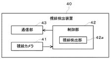
次に、視線検出装置40の構成について説明する。図7は、視線検出装置40の概略構成を示す図である。図7に示すように、視線検出装置40は、視線カメラ41、制御部42、及び、通信部43を備えている。   Next, the configuration of the sight line detection device 40 will be described. FIG. 7 is a view showing a schematic configuration of the sight line detection device 40. As shown in FIG. As shown in FIG. 7, the gaze detection device 40 includes a gaze camera 41, a control unit 42, and a communication unit 43.

視線カメラ41は、視線検出用のカメラであり、ユーザの顔(特に目)を写すためのカメラである。したがって、この視線カメラ41は、被写体となるユーザ(ドライバ)の略正面のインストルメントパネル付近に設けられている。視線カメラ41としては、視線検出に用いることができるものであれば特に限定されるものではなく、可視光カメラや赤外線カメラを用いることができる。なお、赤外線カメラを用いる場合には、赤外線LEDなどを別途設け、ユーザの顔に赤外光を照射した状態で撮影する。   The line-of-sight camera 41 is a camera for detecting the line-of-sight, and is a camera for photographing the face (particularly the eye) of the user. Therefore, the line-of-sight camera 41 is provided near the instrument panel substantially in front of the user (driver) to be the subject. The gaze camera 41 is not particularly limited as long as it can be used for gaze detection, and a visible light camera or an infrared camera can be used. In addition, when using an infrared camera, infrared LED etc. are separately provided and it image | photographs in the state which irradiated the infrared light to the user's face.

制御部42は、例えば、CPU、RAM及びROMなどを備えるマイクロコンピュータであり、視線検出装置40全体を統括的に制御する。制御部42は、視線カメラ41の撮影データを用いてユーザの視線を検出する視線検出部42aを備えている。   The control unit 42 is, for example, a microcomputer including a CPU, a RAM, a ROM, and the like, and controls the entire visual axis detection device 40 in an integrated manner. The control unit 42 includes a gaze detection unit 42 a that detects the gaze of the user using shooting data of the gaze camera 41.

視線検出部42aは、例えば、視線カメラ41で撮影した撮影データの中からユーザの目に該当する画像データを抽出する。そして、目に該当する画像データの中から動きのない点と、動きのある点とを抽出する。そして、視線検出部42aは、これら各点の位置関係に基づいてユーザの視線を検出する。なお、視線の検出方法については後述する。   The visual axis detection unit 42 a extracts, for example, image data corresponding to the user's eyes from among the imaging data captured by the visual axis camera 41. Then, a point without motion and a point with motion are extracted from the image data corresponding to the eye. Then, the sight line detection unit 42a detects the sight line of the user based on the positional relationship between these points. The method of detecting the sight line will be described later.

通信部43は、CAN等の車載LANを介して制御装置10と通信可能に接続されており、制御装置10と各種データの送受信を行う。例えば、視線検出装置40は、視線検出部42aで検出した視線情報を、通信部43を介して制御装置10に送信する。   The communication unit 43 is communicably connected to the control device 10 via an in-vehicle LAN such as CAN, and transmits / receives various data to / from the control device 10. For example, the sight line detection device 40 transmits the sight line information detected by the sight line detection unit 42 a to the control device 10 via the communication unit 43.

<1−3.触感の発生方法と種類>
ここで、タッチセンサ21を振動させることによって触感を発生させる方法と、触感の種類について説明する。
<1-3. How to generate tactile sensation>
Here, a method of generating a tactile sensation by vibrating the touch sensor 21 and types of the tactile sensation will be described.

図5は、タッチセンサ21を模式的に表した図である。上述したように、タッチセンサ21の周囲には、複数の振動素子24が配置されている。なお、本実施の形態では、対向する2辺に並べて配置しているが、これに限定されるものではなく、任意の辺に任意の数の振動素子24を配置すればよい。   FIG. 5 is a view schematically showing the touch sensor 21. As shown in FIG. As described above, the plurality of vibrating elements 24 are disposed around the touch sensor 21. In the present embodiment, two opposing sides are arranged side by side, but the present invention is not limited to this, and an arbitrary number of vibrating elements 24 may be arranged on any side.

触感を発生させるためには、まず制御装置10からの振動制御信号に基づいて振動素子24を高速で振動させる。この高速での振動とは例えば超音波振動である。振動素子24を超音波振動させることでタッチセンサ21の表面を超音波振動させることができる。図5に示すような対向する2辺に配置した振動素子24を振動させればタッチセンサ21全面を略均一に振動させることができる。   In order to generate a tactile sensation, first, the vibrating element 24 is vibrated at high speed based on the vibration control signal from the control device 10. The vibration at this high speed is, for example, ultrasonic vibration. By ultrasonically vibrating the vibration element 24, the surface of the touch sensor 21 can be ultrasonically vibrated. By vibrating the vibrating elements 24 disposed on two opposing sides as shown in FIG. 5, the entire surface of the touch sensor 21 can be vibrated substantially uniformly.

タッチセンサ21表面が超音波振動した状態でタッチセンサ21表面を指で操作すると、指と高速で振動しているタッチセンサ21表面との間に高圧の空気膜が発生して摩擦抵抗が減少する。これにより、ユーザは、振動していない状態に比べてツルツルと滑らかにすべる触感(以下「ツルツル感」という)を得ることができる。   When the surface of the touch sensor 21 is ultrasonically vibrated and the surface of the touch sensor 21 is operated with a finger, a high pressure air film is generated between the finger and the surface of the touch sensor 21 vibrating at high speed to reduce the frictional resistance. . As a result, the user can obtain a smooth and smooth feeling of touch (hereinafter referred to as "slip feeling") as compared to a state where no vibration occurs.

また、タッチセンサ21表面を超音波振動させた状態のときに振動素子24の振動を停止させると、タッチセンサ21表面の超音波振動も停止する。すると、タッチセンサ21表面の摩擦抵抗は、減少していた状態から本来の状態(振動していない状態)に戻る。すなわち、低摩擦の状態から高摩擦の状態に変化する。この場合、ツルツル感のあった触感からひっかかりの感じる触感に変化する。ユーザは、このツルツル感からひっかかりの感じる触感に変化する際にカチッとした触感を得ることができる。このカチッとした触感を以下においては「クリック感」という。   In addition, when the vibration of the vibrating element 24 is stopped when the surface of the touch sensor 21 is ultrasonically vibrated, the ultrasonic vibration of the surface of the touch sensor 21 is also stopped. Then, the frictional resistance on the surface of the touch sensor 21 returns from the reduced state to the original state (non-oscillated state). That is, it changes from a low friction state to a high friction state. In this case, the feeling of slippery feeling changes to the feeling of feeling of catching. The user can obtain a tactile sensation when changing from the slippery feeling to the tactile sensation felt by the user. This click feeling is hereinafter referred to as "click feeling".

また、振動素子24の振動強度に変化をつけてタッチセンサ21表面を超音波振動させると、タッチセンサ21表面を相対的に大振幅で振動させたり小振幅で振動させたりすることが可能になる。これにより、タッチセンサ21表面を高摩擦状態と低摩擦状態とが繰り返された状態にすることができる。つまり、ユーザは、ツルツル感とクリック感とを交互に触感として感じることになり、この場合凸凹した触感やザラザラした触感(以下「ザラザラ感」という)を得ることができる。   In addition, when the vibration intensity of the vibration element 24 is changed to ultrasonically vibrate the surface of the touch sensor 21, the surface of the touch sensor 21 can be vibrated with relatively large amplitude or small amplitude. . Thereby, the surface of the touch sensor 21 can be in a state where the high friction state and the low friction state are repeated. In other words, the user can feel a slippery feeling and a click feeling alternately as a tactile sensation, and in this case, it is possible to obtain an uneven tactile sensation or rough tactile sensation (hereinafter referred to as "roughness").

また、振動の強弱の大きさを変えたり、強弱を変化させる周期を変えることでザラザラ度合いを変化させることができる。これにより、ザラザラ度合いの強いザラザラ感や弱いザラザラ感、またザラザラ感の疎密度感など、段階的に複数種類のザラザラ感を実現することが可能になる。   In addition, the degree of roughness can be changed by changing the magnitude of vibration strength or changing the cycle of changing the strength. As a result, it is possible to realize a plurality of types of rough feeling stepwise, such as a rough feeling with a rough degree, a weak feeling, and a sparse feeling of rough feeling.

このように、本実施の形態では、振動素子24を超音波振動させてタッチセンサ21表面を超音波振動させることで、ユーザに対して触感を与えることができる。また、超音波振動の開始や停止のタイミング、強弱などを適宜制御すれば、その表面の摩擦抵抗を変化させることができ、それを利用することで種々の触感を与えることが可能になっている。   As described above, in the present embodiment, it is possible to give the user a tactile sensation by ultrasonically vibrating the vibrating element 24 and ultrasonically vibrating the surface of the touch sensor 21. In addition, the friction resistance of the surface can be changed by appropriately controlling the timing of start and stop of ultrasonic vibration, strength and the like, and it is possible to give various tactile sensations by using it. .

<1−4.視線の検出と動作状態の制御>
次に、ユーザの視線を検出する処理について説明する。本実施の形態では、上述したように、カメラを用いて撮影した画像データからユーザの視線を検出している。以下、具体的に説明する。
<1-4. Detection of eye gaze and control of movement state>
Next, the process of detecting the line of sight of the user will be described. In the present embodiment, as described above, the line of sight of the user is detected from image data captured using a camera. The details will be described below.

視線検出装置40は、既存のアルゴリズムを用いて、視線カメラ41で撮影した画像データに含まれる人間の顔や目を抽出する。これら既存のアルゴリズムとしては、顔のパーツの形や大きさ、相対位置などを元にして認識するものや、テンプレートマッチングにより認識するもの、3次元の輪郭などの特徴を抽出するものなど、種々のものを用いることができる。   The gaze detection apparatus 40 extracts human face and eyes included in the image data captured by the gaze camera 41 using an existing algorithm. As these existing algorithms, there are various algorithms such as one that recognizes based on shape, size, relative position, etc. of face parts, one that recognizes by template matching, one that extracts features such as three-dimensional contours, etc. The thing can be used.

そして、視線検出装置40は、目に該当する画像データの中から動きのない点を基準点として設定し、動きのある点を動点として設定する。視線カメラ41として可視光カメラを用いた場合には、例えば、目頭を基準点として設定し、虹彩を動点として設定する。そして、視線検出部42aが、虹彩と目頭との位置関係に基づいてユーザの視線を検出する。つまり、ユーザがいずれの方向を見ているかを検出する。例えば、左目の虹彩が目頭から離れていれば、ユーザは左側を見ている等である。   Then, the line-of-sight detection device 40 sets a point without motion from the image data corresponding to the eye as a reference point, and sets a point with motion as a motion point. When a visible light camera is used as the line-of-sight camera 41, for example, the inner corner of the eye is set as a reference point, and the iris is set as a movement point. Then, the gaze detection unit 42a detects the gaze of the user based on the positional relationship between the iris and the inner corners of the eyes. That is, it detects which direction the user is looking at. For example, if the iris of the left eye is far from the eyes and eyes, the user is looking at the left side, and so on.

また、視線カメラ41として赤外線カメラを用いた場合には、例えば、赤外光を照射してできた反射光の角膜上の位置(角膜反射)を基準点として設定し、瞳孔を動点として設定する。そして、視線検出部42aが、角膜反射と瞳孔との位置関係に基づいてユーザの視線を検出する。つまり、ユーザがいずれの方向を見ているかを検出する。例えば、左目の角膜反射よりも瞳孔が目じり側にあれば、ユーザは左側を見ている等である。   When an infrared camera is used as the line-of-sight camera 41, for example, the position on the cornea (corneal reflection) of the reflected light produced by irradiating infrared light is set as a reference point, and the pupil is set as a movement point. Do. Then, the gaze detection unit 42a detects the gaze of the user based on the positional relationship between the corneal reflection and the pupil. That is, it detects which direction the user is looking at. For example, if the pupil is closer to the eye than the corneal reflection of the left eye, the user is looking to the left, etc.

視線検出装置40は、視線を検出すると、その情報を制御装置10に送信する。そして、制御装置10は、視線情報を受信するとその情報に基づいて遠隔操作装置20の動作状態を制御するようになっている。そこで、以下において、制御装置10による遠隔操作装置20の動作状態の制御について説明する。   When the sight line detection device 40 detects the sight line, the information is transmitted to the control device 10. Then, when receiving the line-of-sight information, the control device 10 controls the operation state of the remote control device 20 based on the information. Therefore, control of the operation state of the remote control device 20 by the control device 10 will be described below.

制御装置10は、視線検出装置40から視線情報を受信すると、視線判定部13dが、HUD装置30によって投影された画像が表示される領域(以下「投影画面領域」という)内にユーザの視線が含まれているか否かを判定する。投影画面領域の位置は予め定められているため、視線判定部13dは、視線情報に基づいて導出したユーザの視線(の延長線)が投影画面領域内にあるか否かを判定する。   When the control device 10 receives line-of-sight information from the line-of-sight detection device 40, the line-of-sight determination unit 13d determines that the user's line of sight is within the area where the image projected by the HUD device 30 is displayed (hereinafter referred to as "projection screen area"). Determine if it is included. Since the position of the projection screen area is predetermined, the line-of-sight determination unit 13d determines whether (a line of extension of) the user's line of sight derived based on the line-of-sight information is within the projection screen area.

視線検出装置40は、所定の間隔でユーザの視線を検出している。所定の間隔とは例えば100msである。したがって、制御装置10は、視線検出装置40から100ms毎に視線情報を受信して、各視線情報毎にユーザの視線が投影画面領域内にあるか否かを判定している。   The gaze detection device 40 detects the gaze of the user at a predetermined interval. The predetermined interval is, for example, 100 ms. Therefore, the control device 10 receives the line-of-sight information from the line-of-sight detection device 40 every 100 ms, and determines whether the line of sight of the user is within the projection screen area for each line-of-sight information.

視線判定部13dは、ユーザの視線が投影画面領域内にあるとの判定結果が所定回数以上連続した場合に、ユーザは投影画面領域を見ていると判定する。視線判定部13dは、それ以外の場合には、ユーザは投影画面領域を見ていないと判定する。所定回数は、ユーザが投影画面領域を見ていると判定可能な回数であればよく、適宜設定可能である。   The gaze determination unit 13d determines that the user is looking at the projection screen region when the determination result that the user's gaze is within the projection screen region continues a predetermined number of times or more. Otherwise, the line-of-sight determination unit 13d determines that the user does not look at the projection screen area. The predetermined number of times may be set as appropriate as long as it can be determined that the user is looking at the projection screen area.

ユーザが投影画面領域を見ている場合には、動作制御部13eは、遠隔操作装置20の操作を有効にする。例えば、動作制御部13eが、遠隔操作装置20の電源をオンにする制御をしたり、遠隔操作装置20への操作を受け付ける制御をしたり、遠隔操作装置20から受信した操作位置の情報を有効な情報として処理する等である。   When the user is looking at the projection screen area, the operation control unit 13e validates the operation of the remote control device 20. For example, the operation control unit 13e performs control to turn on the power of the remote control device 20, performs control to receive an operation to the remote control device 20, or validates the information of the operation position received from the remote control device 20. And so on.

一方、ユーザが投影画面領域を見ていない場合には、動作制御部13eは、遠隔操作装置20の操作を無効にする。例えば、動作制御部13eが、遠隔操作装置20の電源をオフにする制御をしたり、遠隔操作装置20への操作を禁止する制御をしたり、遠隔操作装置20から受信した操作位置の情報を無効な情報として処理する等である。   On the other hand, when the user does not look at the projection screen area, the operation control unit 13e invalidates the operation of the remote control device 20. For example, the operation control unit 13e performs control to turn off the power of the remote control device 20, controls to prohibit the operation to the remote control device 20, or information on the operation position received from the remote control device 20. It is processed as invalid information.

<1−5.システムの処理>
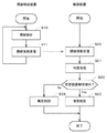
次に、操作システム1の処理について説明する。図8は、視線検出装置40及び制御装置10の処理を示すフローチャートである。視線検出装置40及び制御装置10は、電源が投入されて起動することにより処理を開始する。
<1-5. System processing>
Next, processing of the operation system 1 will be described. FIG. 8 is a flowchart showing processing of the visual axis detection device 40 and the control device 10. The gaze detection device 40 and the control device 10 start processing when the power is turned on and activated.

まず、視線検出装置40は、ユーザの視線を検出する(ステップS10)。これは、上述したように、視線カメラ41で撮影した画像データに基づいて視線検出部42aが基準点及び動点を設定して行う。そして、視線検出装置40は、検出した視線に関する情報(視線情報)を制御装置10に送信する(ステップS11)。   First, the gaze detection apparatus 40 detects the gaze of the user (step S10). As described above, this is performed by setting the reference point and the movement point by the sight line detection unit 42 a based on the image data captured by the sight camera 41. Then, the sight line detection device 40 transmits information on the detected sight line (gaze point information) to the control device 10 (step S11).

視線検出装置40は、この視線検出処理を所定の間隔で繰り返し実行する。所定の間隔とは、例えば100msであるが、これに限定されるものではない。制御装置10が、ユーザが投影画面領域を見ているか否かの判定を行うことができる程度の間隔であればよく、適宜設定可能である。なお、視線検出装置40は、電源がオフしたり、処理の停止指示があると処理を終了する。   The sight line detection device 40 repeatedly executes this sight line detection process at predetermined intervals. The predetermined interval is, for example, 100 ms, but is not limited to this. The interval may be set as long as the control device 10 can determine whether the user is looking at the projection screen area or not. The gaze detection device 40 ends the process when the power is turned off or when the process stop instruction is issued.

そして、制御装置10が視線情報を受信し(ステップS20)、判定処理を実行する(ステップS21)。この判定処理は、ユーザの視線が投影画面領域内にあるか否かを判定する処理である。上述したように、投影画面領域の位置は予め定められているため、視線判定部13dは、ユーザの視線(の延長線)がこの予め定められた領域内に含まれるか否かを判定する。なお、この判定処理は、定期的に受信する全視線情報に対して実行される。   Then, the control device 10 receives the line-of-sight information (step S20), and executes the determination process (step S21). This determination process is a process of determining whether the line of sight of the user is within the projection screen area. As described above, since the position of the projection screen area is predetermined, the line-of-sight determination unit 13d determines whether (the extension of) the line of sight of the user is included in the predetermined area. Note that this determination process is performed on all the line-of-sight information that is periodically received.

そして、制御装置10は、ユーザの視線が投影画面領域に含まれているとの判定結果が、所定回数連続したか否かを判定する(ステップS22)。所定回数連続した場合には(ステップS22でYes)、視線判定部13dは、ユーザが投影画面を見ていると判定し、動作制御部13eが遠隔操作装置20を有効にする(ステップS23)。すなわち、動作制御部13eは、動作状態の制御として、遠隔操作装置20の電源のオンや、操作の受け付けや、遠隔操作装置20からの受信信号の有効化等を実行する。   Then, the control device 10 determines whether or not the determination result that the line of sight of the user is included in the projection screen area has continued a predetermined number of times (step S22). If the operation continues a predetermined number of times (Yes in step S22), the sight-line determining unit 13d determines that the user is looking at the projection screen, and the operation control unit 13e enables the remote control device 20 (step S23). That is, the operation control unit 13 e performs power on of the remote control device 20, reception of an operation, activation of a reception signal from the remote control device 20, and the like as control of the operation state.

一方、所定回数連続していない場合には(ステップS22でNo)、視線判定部13dは、ユーザが投影画面を見ていないと判定し、動作制御部13eが遠隔操作装置20を無効にする(ステップS24)。すなわち、動作制御部13eは、動作状態の制御として、遠隔操作装置20の電源のオフや、操作の禁止や、遠隔操作装置20からの受信信号の無効化等を実行する。   On the other hand, if the user has not seen the projection screen (No at Step S22), the gaze determination unit 13d determines that the user does not look at the projection screen and the operation control unit 13e invalidates the remote control device 20 (No in Step S22) Step S24). That is, the operation control unit 13 e performs powering off of the remote control device 20, prohibition of operation, disabling of a reception signal from the remote control device 20, and the like as control of the operation state.

このように、前方の表示画面を見ながら手元のタッチセンサを操作するような遠隔操作のシステムにおいて、ユーザが表示画面を見ているときだけタッチセンサの操作を有効にするため、安全面での問題が生じることを回避することができると共に、誤操作を低減させることができる。   As described above, in the remote control system in which the touch sensor at hand is operated while looking at the display screen in front, in order to validate the operation of the touch sensor only when the user is looking at the display screen, While being able to avoid that a problem arises, a misoperation can be reduced.

<2.第2の実施の形態>
次に、第2の実施の形態について説明する。第1の実施の形態では、ユーザの視線を検出し、ユーザが投影画面領域を見ているか否かに応じて遠隔操作装置20の動作状態を制御する内容について説明したが、これに限定されるものではない。例えば、ユーザが遠隔操作装置20を見ているか否かに応じて遠隔操作装置20自身の動作状態を制御する内容としてもよい。以下においては、この内容について第1の実施の形態と異なる点を中心に説明する。
<2. Second embodiment>
Next, a second embodiment will be described. In the first embodiment, the content of detecting the line of sight of the user and controlling the operation state of the remote control device 20 according to whether the user is looking at the projection screen area has been described, but the present invention is limited thereto. It is not a thing. For example, the operation state of the remote control device 20 may be controlled according to whether the user is looking at the remote control device 20 or not. In the following, the contents will be described focusing on differences from the first embodiment.

<2−1.構成>
図9は、本実施の形態にかかる操作システム2の概略構成を示す図である。図9に示すように、操作システム2は、第1の実施の形態で説明した操作システム1と略同様の構成を有しており、制御装置14、遠隔操作装置20、HUD装置30及び視線検出装置40を備えている。このうち、遠隔操作装置20、HUD装置30及び視線検出装置40は、第1の実施の形態の各装置と同様の構成である。
<2-1. Configuration>
FIG. 9 is a view showing a schematic configuration of the operation system 2 according to the present embodiment. As shown in FIG. 9, the operation system 2 has substantially the same configuration as the operation system 1 described in the first embodiment, and the control device 14, the remote control device 20, the HUD device 30, and the sight line detection An apparatus 40 is provided. Among these, the remote control device 20, the HUD device 30, and the sight line detection device 40 have the same configuration as the devices of the first embodiment.

そこで、制御装置14の構成について第1の実施の形態との相違点を中心に図10を用いて説明する。図10は、制御装置14の概略構成を示す図である。   Therefore, the configuration of the control device 14 will be described with reference to FIG. 10, focusing on the differences from the first embodiment. FIG. 10 is a view showing a schematic configuration of the control device 14.

図10に示すように、制御装置14は、通信部11、記憶部12、及び、制御部13を備えている。このうち、通信部11及び記憶部12は、第1の実施の形態の各部と同様の構成である。また、制御部13のうち、操作判別部13a、画像生成部13b及び振動制御部13cの機能は、第1の実施の形態で説明した各機能と同様である。これに対して、視線判定部13f及び動作制御部13gの機能が、第1の実施の形態で説明した各機能と相違する。このため、以下においては、視線判定部13f及び動作制御部13gについて説明する。   As shown in FIG. 10, the control device 14 includes a communication unit 11, a storage unit 12, and a control unit 13. Among these, the communication unit 11 and the storage unit 12 have the same configuration as the respective units in the first embodiment. Further, in the control unit 13, the functions of the operation determination unit 13a, the image generation unit 13b, and the vibration control unit 13c are the same as the functions described in the first embodiment. On the other hand, the functions of the line-of-sight determination unit 13 f and the operation control unit 13 g are different from those described in the first embodiment. For this reason, the line-of-sight determination unit 13f and the operation control unit 13g will be described below.

第1の実施の形態の視線判定部13dは、ユーザの視線が投影画面領域内に含まれるか否かを判定するのに対して、本実施の形態の視線判定部13fは、ユーザの視線が遠隔操作装置20のタッチセンサ21が配置された領域(以下「タッチセンサ領域」という)に含まれるか否かを判定する。   The line-of-sight determination unit 13d of the first embodiment determines whether or not the line of sight of the user is included in the projection screen area, whereas the line-of-sight determination unit 13f of the present embodiment determines that the line of sight of the user is It is determined whether the touch sensor 21 of the remote control device 20 is included in an area (hereinafter referred to as a "touch sensor area").

また、第1の実施の形態の動作制御部13eは、ユーザが投影画面領域を見ている場合に遠隔操作装置20を有効にし、見ていない場合に無効にするのに対して、本実施の形態の動作制御部13gは、ユーザがタッチセンサ領域を見ている場合に遠隔操作装置20を無効にし、見ていない場合に有効にする。   Further, the operation control unit 13e according to the first embodiment enables the remote control device 20 when the user is looking at the projection screen area, and makes the remote control device 20 invalid when the user is not looking at the projection screen area. The operation control unit 13 g of the form invalidates the remote control device 20 when the user is looking at the touch sensor area, and enables it when not looking at the touch sensor area.

<2−2.処理>
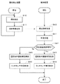
次に、本実施の形態の操作システム2の処理について説明する。図11は、本実施の形態にかかる操作システム2の処理を示すフローチャートである。
2-2. Processing>
Next, processing of the operation system 2 of the present embodiment will be described. FIG. 11 is a flowchart showing processing of the operation system 2 according to the present embodiment.

図11に示すように、まず、視線検出装置40がユーザの視線を検出し(ステップS10)、その結果としての視線情報を制御装置14に送信する(ステップS11)。これらの処理は、第1の実施の形態と同様の処理である。   As shown in FIG. 11, first, the visual axis detection device 40 detects the visual axis of the user (step S10), and transmits the resultant visual axis information to the control device 14 (step S11). These processes are similar to those of the first embodiment.

そして、制御装置14は、視線情報を受信すると(ステップS30)、判定処理を実行する(ステップS31)。この判定処理は、ユーザの視線がタッチセンサ領域内にあるか否かを判定する処理である。本実施の形態においても、タッチセンサ領域の位置が予め定められており、視線判定部13fは、ユーザの視線(の延長線)がこのタッチセンサ領域内に含まれるか否かを判定する。なお、この判定処理は、定期的に受信する全視線情報に対して実行される。   And control device 14 will perform judgment processing (Step S31), if line-of-sight information is received (Step S30). This determination process is a process of determining whether the line of sight of the user is within the touch sensor area. Also in the present embodiment, the position of the touch sensor area is determined in advance, and the line-of-sight determination unit 13 f determines whether (the extension of) the line of sight of the user is included in the touch sensor area. Note that this determination process is performed on all the line-of-sight information that is periodically received.

次に、制御装置14は、ユーザの視線がタッチセンサ領域内にあるとの判定結果が所定回数連続したか否かを判定する(ステップS32)。所定回数連続した場合には(ステップS32でYes)、視線判定部13fは、ユーザがタッチセンサ領域を見ていると判定し、動作制御部13gが遠隔操作装置20を無効にする(ステップS33)。すなわち、動作制御部13gは、動作状態の制御として、遠隔操作装置20の電源のオフや、操作の禁止や、遠隔操作装置20からの受信信号の無効化等を実行する。   Next, the control device 14 determines whether or not the determination result that the line of sight of the user is within the touch sensor area has continued a predetermined number of times (step S32). If the operation continues a predetermined number of times (Yes in step S32), the sight line determination unit 13f determines that the user is looking at the touch sensor area, and the operation control unit 13g invalidates the remote control device 20 (step S33). . That is, the operation control unit 13 g performs powering off of the remote control device 20, prohibition of operation, disabling of a received signal from the remote control device 20, and the like as control of the operation state.

一方、所定回数連続していない場合には(ステップS32でNo)、視線判定部13fでは、ユーザがタッチセンサ領域を見ていないと判定し、動作制御部13gが遠隔操作装置20を有効にする(ステップS34)。すなわち、動作制御部13gは、動作状態の制御として、遠隔操作装置20の電源のオンや、操作の受け付けや、遠隔操作装置20からの受信信号の有効化等を実行する。   On the other hand, when not continuing for a predetermined number of times (No in step S32), the gaze determination unit 13f determines that the user does not look at the touch sensor area, and the operation control unit 13g enables the remote control device 20. (Step S34). That is, the operation control unit 13 g performs power on of the remote control device 20, reception of an operation, activation of a reception signal from the remote control device 20, and the like as control of the operation state.

以上のように、ユーザがタッチセンサ領域を見ている場合には、ユーザであるドライバが前方視界から目を離していることを示しているため、タッチセンサ21の操作を有効にすると安全面の問題が懸念される。そこで、本実施の形態では、ユーザがタッチセンサ21を見ている場合には、タッチセンサ21の動作状態を無効にし、見ていない場合に有効にするような制御を行っている。   As described above, when the user is looking at the touch sensor area, it indicates that the driver who is the user is looking away from the front view. The problem is concerned. Therefore, in the present embodiment, when the user is looking at the touch sensor 21, control is performed to invalidate the operation state of the touch sensor 21 and to enable the operation state when not looking at the touch sensor 21.

これにより、前方の表示画面を見ながら手元のタッチセンサを操作するような遠隔操作のシステムにおいて、ユーザがタッチセンサを見ていないときだけタッチセンサの操作を有効にするため、安全面での問題が生じることを回避することができると共に、誤操作を低減させることができる。   As a result, in a remote control system in which the touch sensor at hand is operated while looking at the front display screen, the operation of the touch sensor is enabled only when the user is not looking at the touch sensor, which causes a problem in safety. Can be avoided and erroneous operation can be reduced.

<3.第3の実施の形態>
次に、第3の実施の形態について説明する。第1の実施の形態では、ユーザの視線を検出し、ユーザが投影画面領域を見ているか否かに応じて遠隔操作装置20の動作状態を制御する内容について説明した。本実施の形態では、他の操作装置をさらに備え、ユーザの視線に応じて遠隔操作装置20及び他の操作装置の動作状態を併せて制御する内容である。以下においては、この内容について第1の実施の形態と異なる点を中心に説明する。
<3. Third embodiment>
Next, a third embodiment will be described. In the first embodiment, the content of detecting the line of sight of the user and controlling the operation state of the remote control device 20 according to whether or not the user is looking at the projection screen area has been described. In the present embodiment, another operation device is further provided, and the operation states of the remote control device 20 and the other operation device are controlled together in accordance with the line of sight of the user. In the following, the contents will be described focusing on differences from the first embodiment.

<3−1.構成>
図12は、本実施の形態に係る操作システム3が搭載される車室内の様子を示す図である。図13は、操作システム3の概略構成を示す図である。図12及び図13に示すように、操作システム3は、第1の実施の形態で説明した操作システム1とほぼ同様の構成を有しており、制御装置15、遠隔操作装置20、HUD装置30及び視線検出装置40を備えている。このうち、遠隔操作装置20、HUD装置30及び視線検出装置40は、第1の実施の形態の各装置と同様の構成である。
<3-1. Configuration>
FIG. 12 is a view showing the interior of the passenger compartment in which the operation system 3 according to the present embodiment is mounted. FIG. 13 is a view showing a schematic configuration of the operation system 3. As shown in FIGS. 12 and 13, the operation system 3 has substantially the same configuration as the operation system 1 described in the first embodiment, and the control device 15, the remote control device 20, and the HUD device 30. And the visual axis detection device 40. Among these, the remote control device 20, the HUD device 30, and the sight line detection device 40 have the same configuration as the devices of the first embodiment.

そこで、制御装置15の構成について第1の実施の形態との相違点を中心に説明する。制御装置15は、車両のセンターコンソールなどのユーザが視認可能な位置に設けられ、少なくとも表示部とタッチセンサを有する電子機器である。また、制御装置15は、遠隔操作装置20、HUD装置30及び視線検出装置40の各々と電気的に接続されており、各装置との間で信号の送受信が可能である。   Therefore, the configuration of the control device 15 will be described focusing on the differences from the first embodiment. The control device 15 is an electronic device provided at a position that can be viewed by a user, such as a center console of a vehicle, and having at least a display unit and a touch sensor. Further, the control device 15 is electrically connected to each of the remote control device 20, the HUD device 30, and the sight line detection device 40, and can transmit and receive signals with each device.

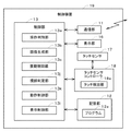
図14は、制御装置15の概略構成を示す図である。図14に示すように、制御装置15は、通信部11、記憶部12、制御部13、表示部16、タッチセンサ17、及び、タッチセンサコントローラ18を備えている。このうち、通信部11及び記憶部12は、第1の実施の形態で説明した各部と同様の構成である。   FIG. 14 is a view showing a schematic configuration of the control device 15. As shown in FIG. As shown in FIG. 14, the control device 15 includes a communication unit 11, a storage unit 12, a control unit 13, a display unit 16, a touch sensor 17, and a touch sensor controller 18. Among these, the communication unit 11 and the storage unit 12 have the same configuration as the units described in the first embodiment.

また、制御部13のうち、操作判別部13a、画像生成部13b、振動制御部13c及び視線判定部13dは、第1の実施の形態で説明した制御部13が有する各機能と同様である。これに対して、動作制御部13hは、第1の実施の形態の動作制御部13eとは一部異なる機能であり、表示制御部13iは、本実施の形態の制御部13にて新たに実現される機能である。   Further, in the control unit 13, the operation determination unit 13a, the image generation unit 13b, the vibration control unit 13c, and the line-of-sight determination unit 13d are the same as the functions of the control unit 13 described in the first embodiment. On the other hand, the operation control unit 13 h has a function different from that of the operation control unit 13 e of the first embodiment, and the display control unit 13 i is newly realized by the control unit 13 of the present embodiment. Function.

動作制御部13hは、ユーザの視線に応じて遠隔操作装置20及びタッチセンサ17の動作状態を制御する。例えば、ユーザの視線がHUD装置30の投影画面領域の方向を見ている場合に、動作制御部13hは、遠隔操作装置20のタッチセンサ21(第1のタッチセンサ)の操作を有効にすると共にタッチセンサ17(第2のタッチセンサ)の操作を無効にする等である。   The operation control unit 13 h controls the operation states of the remote control device 20 and the touch sensor 17 according to the line of sight of the user. For example, when the line of sight of the user is looking at the direction of the projection screen area of the HUD device 30, the operation control unit 13h validates the operation of the touch sensor 21 (first touch sensor) of the remote control device 20. The operation of the touch sensor 17 (second touch sensor) is invalidated.

表示制御部13iは、エアコンやオーディオなどの設定値を調整するための調整画像を表示部16に表示させる制御を行う。また、制御装置15がナビゲーション機能を有している場合には、表示制御部13iは、地図画像やナビゲーション画像を表示部16に表示させる制御も行う。   The display control unit 13i controls the display unit 16 to display an adjustment image for adjusting setting values of an air conditioner, audio, and the like. In addition, when the control device 15 has a navigation function, the display control unit 13i also performs control to display a map image or a navigation image on the display unit 16.

表示部16は、調整画像や地図画像などを表示する表示装置であり、例えば液晶ディスプレイや有機EL(Electro Luminescence)ディスプレイ等である。   The display unit 16 is a display device that displays an adjustment image, a map image, and the like, and is, for example, a liquid crystal display or an organic EL (Electro Luminescence) display.

タッチセンサ17は、ユーザが操作内容を入力する平板状のセンサーである。タッチセンサ17は、表示部16の表示面上に(ユーザ側の面上に)設けられている。すなわち、表示部16及びその表示面上に設けられたタッチセンサ17がいわゆるタッチパネルとして機能する。   The touch sensor 17 is a flat sensor that allows the user to input an operation content. The touch sensor 17 is provided on the display surface of the display unit 16 (on the surface on the user side). That is, the display unit 16 and the touch sensor 17 provided on the display surface thereof function as a so-called touch panel.

表示部16の表示面には、適宜、ユーザの指示を受け付けるコマンドボタンが表示される。ユーザは、このようなコマンドボタンの領域に対応するタッチセンサ17の操作面中の領域に指でタッチすることで、コマンドボタンに関連付けられた指示を制御装置15に行うことができる。   On the display surface of the display unit 16, a command button for receiving an instruction of the user is displayed as appropriate. The user can give an instruction associated with the command button to the control device 15 by touching the area in the operation surface of the touch sensor 17 corresponding to the area of the command button with a finger.

また、タッチセンサ17に振動素子を配置して、ユーザのタッチセンサ17の操作に応じて振動素子を振動させるようにしてもよい。振動素子が振動することでタッチセンサ17の操作面も振動してユーザに対して触感を与えることができる。タッチセンサ17の方式は、上記タッチセンサ21と同様に、例えば静電容量方式を用いることができる。   Alternatively, a vibrating element may be disposed on the touch sensor 17 and the vibrating element may be vibrated according to the operation of the touch sensor 17 by the user. By vibrating the vibrating element, the operation surface of the touch sensor 17 is also vibrated, and a tactile sensation can be given to the user. As a method of the touch sensor 17, for example, an electrostatic capacitance method can be used similarly to the touch sensor 21.

タッチセンサコントローラ18も、上記タッチセンサコントローラ22と同様の構成である。すなわち、タッチセンサコントローラ18は、タッチセンサ17で生じた信号に基づいて、タッチセンサ17の操作面中のユーザがタッチした位置を検出するタッチ検出部18aを備えており、このタッチ検出部18aが、ユーザがタッチしたか否かと、タッチした位置とを検出する。   The touch sensor controller 18 also has the same configuration as the touch sensor controller 22. That is, the touch sensor controller 18 includes the touch detection unit 18a that detects the position touched by the user in the operation surface of the touch sensor 17 based on the signal generated by the touch sensor 17. The touch detection unit 18a Whether the user has touched or not and the touched position are detected.

<3−2.処理>
次に、本実施の形態の操作システム3の処理について説明する。図15は、本実施の形態にかかる操作システム3の処理を示すフローチャートである。
<3-2. Processing>
Next, processing of the operation system 3 of the present embodiment will be described. FIG. 15 is a flowchart showing the process of the operation system 3 according to the present embodiment.

図15に示すように、まず、視線検出装置40がユーザの視線を検出し(ステップS10)、その結果としての視線情報を制御装置15に送信する(ステップS11)。これらの処理は、第1の実施の形態と同様の処理である。   As shown in FIG. 15, first, the visual axis detection device 40 detects the visual axis of the user (step S10), and transmits the resultant visual axis information to the control device 15 (step S11). These processes are similar to those of the first embodiment.

そして、制御装置15は、視線情報を受信すると(ステップS40)、判定処理を実行して、ユーザの視線が投影画面領域に含まれているか否かを判定する(ステップS41)。次いで、ユーザの視線が投影画面領域に含まれているとの判定結果が所定回数連続したか否かを判定する(ステップS42)。これら各処理も、第1の実施の形態の処理(ステップS20、S21及びS22)と同様の処理である。   Then, when receiving the line-of-sight information (step S40), the control device 15 executes a determination process to determine whether the line of sight of the user is included in the projection screen area (step S41). Next, it is determined whether or not the determination result that the line of sight of the user is included in the projection screen area has continued a predetermined number of times (step S42). These respective processes are also the same as the processes (steps S20, S21 and S22) of the first embodiment.

そして、所定回数連続した場合には(ステップS42でYes)、視線判定部13dは、ユーザが投影画面を見ていると判定する。そして、動作制御部13hが、遠隔操作装置20を有効にする(ステップS43)と共に、制御装置15のタッチセンサ17を無効にする(ステップS44)。すなわち、動作制御部13hは、動作状態の制御として、遠隔操作装置20の電源のオンや、操作の受け付けや、遠隔操作装置20からの受信信号の有効化等を実行する。また、動作制御部13hは、動作状態の制御として、タッチセンサ17への操作の禁止や、タッチ検出部18aが取得した情報の無効化等を実行する。また、タッチセンサ17を無効にする際には、表示部16が、黒画像や白画像などのタッチセンサ17への操作ができないことをユーザに認識させる画像を表示してもよい。   Then, in the case where the predetermined number of times have been continued (Yes in step S42), the sight line determination unit 13d determines that the user is looking at the projection screen. Then, the operation control unit 13 h validates the remote control device 20 (step S 43) and invalidates the touch sensor 17 of the control device 15 (step S 44). That is, the operation control unit 13 h performs power on of the remote control device 20, reception of an operation, activation of a reception signal from the remote control device 20, and the like as control of the operation state. In addition, the operation control unit 13 h performs, as control of the operation state, prohibition of an operation on the touch sensor 17, invalidation of information acquired by the touch detection unit 18 a, and the like. Further, when disabling the touch sensor 17, the display unit 16 may display an image that allows the user to recognize that the touch sensor 17 can not be operated, such as a black image and a white image.

一方、所定回数連続していない場合には(ステップS42でNo)、視線判定部13dは、ユーザが投影画面を見ていないと判定する。そして、動作制御部13hが、遠隔操作装置20を無効にする(ステップS45)と共に、制御装置15のタッチセンサ17を有効にする(ステップS46)。すなわち、動作制御部13hは、動作状態の制御として、遠隔操作装置20の電源のオフや、操作の禁止や、遠隔操作装置20からの受信信号の無効化等を実行する。また、動作制御部13hは、動作状態の制御として、タッチセンサ17への操作の受け付けや、タッチ検出部18aが取得した情報の有効化等を実行する。   On the other hand, if the user does not continue the predetermined number of times (No in step S42), the gaze determination unit 13d determines that the user has not viewed the projection screen. Then, the operation control unit 13h invalidates the remote control device 20 (step S45), and enables the touch sensor 17 of the control device 15 (step S46). That is, the operation control unit 13 h performs powering off of the remote control device 20, prohibition of operation, disabling of a received signal from the remote control device 20, and the like as control of the operation state. In addition, the operation control unit 13h executes, as control of the operation state, acceptance of an operation on the touch sensor 17, activation of information acquired by the touch detection unit 18a, and the like.

このように、前方視界に表示された画面を見ながら手元のタッチセンサを操作するような遠隔操作装置と、前方視界以外の表示画面を見ながら操作する操作装置とを備えたシステムにおいても、ユーザが前方視界に表示された画面を見ているときだけ手元のタッチセンサの操作を有効にして、前方視界以外の表示画面の操作を無効にするため、安全面での問題が生じることを回避することができると共に、誤操作を低減させることができる。   As described above, even in a system provided with a remote control device that operates the touch sensor at hand while viewing the screen displayed in the front view, and an operating device that operates while viewing the display screen other than the front view Only when the user is looking at the screen displayed in the front view, the operation of the touch sensor at hand is enabled and the operation of the display screen other than the front view is nullified, thereby avoiding the problem in safety. While being able to do, it is possible to reduce erroneous operation.

<4.第4の実施の形態>
次に、第4の実施の形態について説明する。本実施の形態に係る操作システムは、ユーザの視線を検出してユーザが見ている装置に関する操作を遠隔操作装置で行うことができるようにするシステムである。
<4. Fourth embodiment>
Next, a fourth embodiment will be described. The operation system according to the present embodiment is a system that enables the remote control device to perform an operation regarding a device that the user is looking at by detecting the line of sight of the user.

<4−1.構成>
図16は、本実施の形態に係る操作システム4が搭載される車室内の様子を示す図である。図17は、操作システム4の概略構成を示す図である。図16及び図17に示すように、操作システム4は、第3の実施の形態で説明した操作システム1とほぼ同様の構成を有しており、制御装置19、遠隔操作装置20、HUD装置30及び視線検出装置40を備えている。このうち、遠隔操作装置20、HUD装置30及び視線検出装置40は、第1の実施の形態の各装置と同様の構成である。
<4-1. Configuration>
FIG. 16 is a view showing the inside of a vehicle compartment in which the operation system 4 according to the present embodiment is mounted. FIG. 17 is a view showing a schematic configuration of the operation system 4. As shown in FIGS. 16 and 17, the operation system 4 has substantially the same configuration as the operation system 1 described in the third embodiment, and the control device 19, the remote control device 20, and the HUD device 30. And the visual axis detection device 40. Among these, the remote control device 20, the HUD device 30, and the sight line detection device 40 have the same configuration as the devices of the first embodiment.

そこで、制御装置19の構成について第3の実施の形態との相違点を中心に説明する。制御装置19は、車両のセンターコンソールなどのユーザが視認可能な位置に設けられ、少なくとも表示部とタッチセンサを有する電子機器である。また、制御装置19は、遠隔操作装置20、HUD装置30及び視線検出装置40の各々と電気的に接続されており、各装置との間で信号の送受信が可能である。   Therefore, the configuration of the control device 19 will be described focusing on the differences from the third embodiment. The control device 19 is an electronic device provided at a position that can be viewed by a user, such as a center console of a vehicle, and having at least a display unit and a touch sensor. Further, the control device 19 is electrically connected to each of the remote control device 20, the HUD device 30, and the sight line detection device 40, and can transmit and receive signals with each device.

図18は、制御装置19の概略構成を示す図である。図18に示すように、制御装置19は、通信部11、記憶部12、制御部13、表示部16、タッチセンサ17、及び、タッチセンサコントローラ18を備えている。このうち、制御部13以外の各部は第3の実施の形態で説明した各部と同様の構成である。   FIG. 18 is a view showing a schematic configuration of the control device 19. As shown in FIG. 18, the control device 19 includes a communication unit 11, a storage unit 12, a control unit 13, a display unit 16, a touch sensor 17, and a touch sensor controller 18. Among these, each unit other than the control unit 13 has the same configuration as each unit described in the third embodiment.

また、制御部13のうち、操作判別部13a、画像生成部13b、振動制御部13c及び表示制御部13iは、第3の実施の形態で説明した制御部13が有する各機能と同様である。これに対して、視線判定部13j及び動作制御部13kは、第3の実施の形態の各部とは一部異なる機能を有している。   Further, in the control unit 13, the operation determination unit 13a, the image generation unit 13b, the vibration control unit 13c, and the display control unit 13i are the same as the functions of the control unit 13 described in the third embodiment. On the other hand, the line-of-sight determination unit 13j and the operation control unit 13k have functions that are partially different from the respective units of the third embodiment.

視線判定部13jは、ユーザの視線方向が車両内のどの領域に含まれるのかを判定する。すなわち、ユーザが車両内のどの位置を見ているのかを判定する。また、視線判定部13jは、ユーザの視線方向に配置されている電子機器や車両設備など(以下「装置等」という)を判定する。すなわち、ユーザが見ている装置等が何であるのかを判定する。   The gaze determination unit 13j determines which area in the vehicle the user's gaze direction is included in. That is, it is determined which position in the vehicle the user is looking at. Further, the line-of-sight determination unit 13j determines electronic devices, vehicle facilities, and the like (hereinafter referred to as “devices and the like”) arranged in the direction of the user's line of sight. That is, it is determined what the device etc. the user is looking at.

具体的には、視線判定部13jは、視線検出装置40が検出した視線情報を取得すると、ユーザの視線方向が含まれる領域を判定する。そして、判定された領域と車両内の装置等の配置情報とを比較して、ユーザの視線方向に配置されている装置等を判定する。   Specifically, upon acquiring the line-of-sight information detected by the line-of-sight detection device 40, the line-of-sight determination unit 13j determines an area including the line-of-sight direction of the user. Then, the determined area is compared with the arrangement information of the device etc. in the vehicle to determine the device etc. arranged in the user's gaze direction.

装置等とは、例えば、表示装置やエアコン吹き出し口やオーディオ装置などである。この例の場合、例えば、センターコンソールの中央部分に相当する位置には表示装置が配置されているという情報や、ダッシュボード左側に相当する位置にはエアコンの吹き出し口50が配置されているという情報が配置情報となる。このように、配置情報は、装置等と、その装置等が配置されている車両内空間における位置とを対応付けた情報である。   The device or the like is, for example, a display device, an air conditioner outlet or an audio device. In the case of this example, for example, information that the display device is disposed at the position corresponding to the central portion of the center console, and information that the air outlet 50 is disposed at the position corresponding to the left side of the dashboard. Is the placement information. As described above, the arrangement information is information in which the device or the like is associated with the position in the in-vehicle space in which the device or the like is arranged.

動作制御部13kは、ユーザの視線方向に配置されている装置等の種類に応じて、遠隔操作装置20の動作状態を制御する。例えば、ユーザの視線がエアコン吹き出し口の方向を向いている場合には、動作制御部13kは、遠隔操作装置20をエアコンの設定調整が可能なモードとなるように制御する等である。   The operation control unit 13k controls the operation state of the remote control device 20 according to the type of the device or the like arranged in the direction of the user's line of sight. For example, when the line of sight of the user points in the direction of the air conditioner outlet, the operation control unit 13k controls the remote control device 20 to be in a mode in which settings of the air conditioner can be adjusted.

<4−2.処理>
次に、本実施の形態の操作システム4の処理について説明する。図19は、本実施の形態にかかる操作システム4の処理を示すフローチャートである。
<4-2. Processing>
Next, processing of the operation system 4 of the present embodiment will be described. FIG. 19 is a flowchart showing the process of the operation system 4 according to the present embodiment.

図19に示すように、まず、視線検出装置40がユーザの視線を検出し(ステップS10)、その結果としての視線情報を制御装置19に送信する(ステップS11)。これらの処理は、第1の実施の形態と同様の処理である。   As shown in FIG. 19, first, the visual axis detection device 40 detects the visual axis of the user (step S10), and transmits the resultant visual axis information to the control device 19 (step S11). These processes are similar to those of the first embodiment.

そして、制御装置19は、視線情報を受信すると(ステップS50)、領域判定処理を実行する(ステップS51)。この領域判定処理は、ユーザの視線方向に対応する車両内の領域を判定する処理である。視線判定部13jは、ユーザの視線の延長線が車両内のどの領域に含まれるかを判定する。なお、この領域判定処理は、定期的に受信する全視線情報に対して実行される。   Then, when receiving the line-of-sight information (step S50), the control device 19 executes the area determination process (step S51). The area determination process is a process of determining an area in the vehicle corresponding to the user's gaze direction. The gaze determination unit 13j determines which region in the vehicle the extension line of the user's gaze is included in. This area determination process is performed on all the line-of-sight information received periodically.

そして、制御装置19は、ユーザの視線が同じ領域内にあるとの判定結果が、所定回数連続したか否かを判定する(ステップS52)。つまり、ユーザが同じ領域を一定時間見ていたか否かを判定している。所定回数連続しない場合には(ステップS52でNo)、ユーザは同じ領域を見続けていないとして処理を終了する。   Then, the control device 19 determines whether or not the determination result that the line of sight of the user is in the same area has continued a predetermined number of times (step S52). That is, it is determined whether the user has seen the same area for a certain period of time. If the user does not continue looking at the same area (NO at step S52), the process ends, assuming that the user does not keep looking at the same area.

一方、所定回数連続した場合には(ステップS52)、制御装置19は、装置判定処理を実行する(ステップS53)。すなわち、視線判定部13jは、ユーザの視線が所定回数連続して含まれた領域内に存在する装置等が何であるかを判定する。すなわち、ユーザが何の装置等を見ているかを判定する。本実施の形態では、車室内のどの領域に何の装置等が配置されているかの配置情報が予め定められており、視線判定部13dは、この配置情報に基づいて、ユーザの視線方向に存在する装置等を判定する。   On the other hand, when it has continued a predetermined number of times (step S52), the control device 19 executes an apparatus determination process (step S53). That is, the line-of-sight determination unit 13j determines what devices or the like exist in the area in which the line of sight of the user is continuously included a predetermined number of times. That is, it is determined what device the user is looking at. In the present embodiment, arrangement information on which area of the vehicle interior is arranged in advance is determined in advance, and the line-of-sight determination unit 13d exists in the direction of the user's line of sight based on the arrangement information. Determine the devices to be

そして、制御装置19は、モード制御処理を実行する(ステップS54)。すなわち、動作制御部13kは、ユーザの視線方向に存在すると判定された装置等に対応したモードとなるように遠隔操作装置20やHUD装置30を制御する。   Then, the control device 19 executes mode control processing (step S54). That is, the operation control unit 13k controls the remote control device 20 and the HUD device 30 so as to be in a mode corresponding to a device or the like determined to be present in the user's gaze direction.

例えば、視線判定部13jが、ユーザの視線がダッシュボード左側の領域にあると所定回数連続して判定した場合には、視線判定部13jは、さらに、配置情報に基づいてその領域にはエアコンの吹き出し口が存在すると判定する。すると、動作制御部13kは、遠隔操作装置20及びHUD装置30をエアコンの操作が可能なモードに制御する。具体的には、動作制御部13kのモード制御により、HUD装置30が温度調整や風量調整などの調整像を投影表示し、遠隔操作装置20がタッチセンサ21にて調整画像に対応した入力操作を受け付け可能な状態になる。すなわち、ユーザがエアコンの調整操作が可能なエアコン操作モードが起動する。   For example, when the line-of-sight determination unit 13j determines that the line-of-sight of the user is in the area on the left side of the dashboard a predetermined number of times consecutively, the line-of-sight determination unit 13j further It determines that the outlet exists. Then, the operation control unit 13k controls the remote control device 20 and the HUD device 30 to a mode in which the air conditioner can be operated. Specifically, the mode control of the operation control unit 13k causes the HUD device 30 to project and display an adjustment image such as temperature adjustment and air volume adjustment, and the remote control device 20 performs an input operation corresponding to the adjustment image by the touch sensor 21. It will be in an acceptable state. That is, the air conditioner operation mode in which the user can adjust the air conditioner is activated.

そして、制御装置19は、再び視線検出装置40から視線情報を受信して(ステップS55)、判定処理を実行する(ステップS56)。そして、制御装置19は、ユーザの視線が投影画面領域に含まれているとの判定結果が、所定回数連続したか否かを判定する(ステップS57)。   Then, the control device 19 receives the line-of-sight information again from the line-of-sight detection device 40 (step S55), and executes the determination process (step S56). Then, the control device 19 determines whether or not the determination result that the line of sight of the user is included in the projection screen area has continued a predetermined number of times (step S57).

そして、判定結果が所定回数連続した場合には(ステップS57でYes)、動作制御部13kが遠隔操作装置20を有効にする(ステップS58)。一方、判定結果が所定回数連続していない場合には(ステップS57でNo)、動作制御部13kが遠隔操作装置20を無効にする(ステップS59)。これら各処理は、第1の実施の形態のステップS20〜S24と同様の処理である。   When the determination result continues a predetermined number of times (Yes in step S57), the operation control unit 13k enables the remote control device 20 (step S58). On the other hand, when the determination result does not continue for the predetermined number of times (No in step S57), the operation control unit 13k invalidates the remote control device 20 (step S59). Each of these processes is the same process as steps S20 to S24 in the first embodiment.

なお、ステップS52にて所定回数連続していないと判定した場合においても、遠隔操作装置20への操作を無効にする。この場合、所定回数連続していないと判定されると、動作制御部13kは、動作状態の制御として、遠隔操作装置20の電源のオフや、操作の禁止や、遠隔操作装置20からの受信信号の無効化等を実行する。   Even when it is determined in step S52 that the operation has not been performed a predetermined number of times, the operation on the remote control device 20 is invalidated. In this case, when it is determined that the operation has not been performed a predetermined number of times, the operation control unit 13k turns off the power of the remote control device 20, prohibits operation, or receives a signal from the remote control device 20 as control of the operation state. Perform the invalidation of

このように、ユーザが実際に見ている装置に対応する操作モードが起動するため、ユーザは手元を見ることなく所望の装置を操作することが可能となり利便性が向上すると共に、誤操作を低減させることが可能になる。また、ユーザが表示画面を見ているときだけタッチセンサの操作を有効にするため、安全面での問題が生じることを回避することができると共に、誤操作を低減させることができる。   As described above, since the operation mode corresponding to the device actually viewed by the user is activated, the user can operate the desired device without looking at the hand, which improves convenience and reduces erroneous operations. It becomes possible. In addition, since the operation of the touch sensor is enabled only when the user is looking at the display screen, it is possible to avoid the occurrence of a problem in terms of safety, and to reduce erroneous operations.

なお、ステップS52での所定回数とステップS57での所定回数とでは、ステップS57の所定回数を多くすることが好ましい。すなわち、ユーザが投影画面領域を見ているかの決定判断の時間は、ユーザが車両内のどの領域を見ているかの決定判断の時間よりも短くすることが好ましい。また、各判断の決定時には対応する効果音を出力することが好ましい。   The predetermined number of times in step S57 is preferably increased between the predetermined number of times in step S52 and the predetermined number of times in step S57. That is, it is preferable that the time for determining whether the user is looking at the projection screen area is shorter than the time for determining which area in the vehicle the user is looking at. Further, it is preferable to output a corresponding sound at the time of determination of each determination.

また、本実施の形態においては、制御装置19がモード制御処理(ステップS54)を実行すると、遠隔操作装置20への操作を有効にする構成としてもよい。この場合、制御装置19は、図19のステップS55〜S59の処理は行わず、ユーザの操作を受け付け可能な状態となる。また、ステップS52でNoの場合には処理は終了する。   Further, in the present embodiment, when the control device 19 executes the mode control process (step S54), the operation to the remote control device 20 may be validated. In this case, the control device 19 does not perform the processing of steps S55 to S59 of FIG. Moreover, in the case of No at step S52, the process ends.

<5.変形例>
以上、本発明の実施の形態について説明してきたが、この発明は上記各実施の形態に限定されるものではなく様々な変形が可能である。以下では、このような変形例について説明する。上記各実施の形態及び以下で説明する形態を含む全ての形態は、適宜に組み合わせ可能である。
<5. Modified example>
As mentioned above, although embodiment of this invention was described, this invention is not limited to said each embodiment, A various deformation | transformation is possible. Below, such a modification is demonstrated. All forms including the above-described embodiments and the forms described below can be combined as appropriate.

上記各実施の形態では、操作システムは車両に搭載され、安全面での問題を回避するシステムの例について説明している。すなわち、例えば、ユーザがHUD装置の投影画面を見ていないときは遠隔操作装置への操作を無効にする等である。しかしながら、車両が停車しているときは、ユーザが遠隔操作装置を操作しても安全面に問題が生じることはないため、必ずしもこのような場合にまでも無効にする必要はない。   In each of the above embodiments, the operation system is mounted on a vehicle, and an example of a system that avoids the problem in safety is described. That is, for example, when the user does not look at the projection screen of the HUD device, the operation on the remote control device is invalidated. However, when the vehicle is at a stop, there is no problem in safety even if the user operates the remote control device, and therefore, it is not necessary to invalidate in such a case.

したがって、上記各実施の形態における操作システムは、車両が停車している場合には、遠隔操作装置への操作の無効化処理は行わない構成としてもよい。車両が停車している場合とは、例えば、車速が0の場合やパーキングブレーキがオンの場合などである。   Therefore, the operation system in each of the above embodiments may be configured so as not to perform the invalidation process of the operation on the remote control device when the vehicle is stopped. The case where the vehicle is stopped is, for example, the case where the vehicle speed is 0 or the case where the parking brake is on.

また、上記各実施の形態では、プログラムに従ったCPUの演算処理によってソフトウェア的に各種の機能が実現されると説明したが、これら機能のうちの一部は電気的なハードウェア回路により実現されてもよい。また逆に、ハードウェア回路によって実現されるとした機能のうちの一部は、ソフトウェア的に実現されてもよい。   In each of the above embodiments, it has been described that various functions are realized in software by arithmetic processing of the CPU according to a program, but some of these functions are realized by an electrical hardware circuit. May be Conversely, some of the functions implemented by the hardware circuit may be implemented as software.

1・2・3・4 操作システム
10・14・15・19 制御装置
20 遠隔操作装置
30 HUD装置
40 音声出力装置
1 · 2 · 3 · 4 operation system 10 · 14 · 15 · 19 Control device 20 Remote control device 30 HUD device 40 Audio output device

Claims (4)

車両に搭載される操作システムであって、
前記車両のユーザが操作可能な位置に配置されたタッチセンサと、
前記車両の前方方向であって、前記タッチセンサとは異なる箇所に操作画面を表示する表示装置と、
前記ユーザの視線を検出する視線検出装置と、を備え、
ユーザの視線が、前記タッチセンサが配置されている領域外の、前記操作画面が表示されている領域内にある場合には、前記タッチセンサへの操作を有効にすることを特徴とする操作システム。
An operation system mounted on a vehicle,
A touch sensor disposed at a position where the user of the vehicle can operate;
A display device that displays an operation screen at a location in front of the vehicle that is different from the touch sensor;
A gaze detection device for detecting the gaze of the user;
An operation system characterized in that when the line of sight of the user is outside the area where the touch sensor is arranged and within the area where the operation screen is displayed, the operation on the touch sensor is validated. .
請求項1に記載の操作システムにおいて、
前記タッチセンサには、ユーザに対して触感を付与する触感付与手段が設けられていることを特徴とする操作システム。
In the operation system according to claim 1,
The operation system according to the present invention, wherein the touch sensor is provided with a tactile sensation giving means for giving a tactile sensation to the user.
請求項1に記載の操作システムにおいて、
前記車両が停車している場合には、ユーザの視線が、前記操作画面が表示されている領域内にない場合でも、前記タッチセンサへの操作の無効化を行わないことを特徴とする操作システム。
In the operation system according to claim 1,
When the vehicle is stopped, the operation system is characterized in that the operation on the touch sensor is not invalidated even when the line of sight of the user is not within the area where the operation screen is displayed. .
請求項1に記載の操作システムにおいて、
前記表示装置は、ユーザの略正面のフロントガラス部分に、前記操作画面を投影して表示させるヘッドアップディスプレイ装置であることを特徴とする操作システム。
In the operation system according to claim 1,
The operation system characterized in that the display device is a head-up display device which projects and displays the operation screen on a windshield portion substantially in front of a user.
JP2014247821A 2014-12-08 2014-12-08 Operation system Active JP6549839B2 (en)

Priority Applications (1)

Application Number Priority Date Filing Date Title
JP2014247821A JP6549839B2 (en) 2014-12-08 2014-12-08 Operation system

Applications Claiming Priority (1)

Application Number Priority Date Filing Date Title
JP2014247821A JP6549839B2 (en) 2014-12-08 2014-12-08 Operation system

Publications (3)

Publication Number Publication Date
JP2016110424A JP2016110424A (en) 2016-06-20
JP2016110424A5 JP2016110424A5 (en) 2018-01-18
JP6549839B2 true JP6549839B2 (en) 2019-07-24

Family

ID=56124341

Family Applications (1)

Application Number Title Priority Date Filing Date
JP2014247821A Active JP6549839B2 (en) 2014-12-08 2014-12-08 Operation system

Country Status (1)

Country Link
JP (1) JP6549839B2 (en)

Families Citing this family (4)

* Cited by examiner, † Cited by third party
Publication number Priority date Publication date Assignee Title
CN109547970A (en) * 2017-08-11 2019-03-29 法雷奥舒适驾驶助手公司 The method of safety is provided for the long-range control manipulation for motor vehicles
JP7141215B2 (en) * 2018-01-10 2022-09-22 株式会社デンソーテン Operation input device and touch panel
JP7344057B2 (en) 2019-09-10 2023-09-13 株式会社東海理化電機製作所 Control device, control method, and program
JP7194160B2 (en) * 2020-12-08 2022-12-21 株式会社デンソーテン Movement guidance device and movement guidance method

Family Cites Families (4)

* Cited by examiner, † Cited by third party
Publication number Priority date Publication date Assignee Title
JP5206314B2 (en) * 2008-10-28 2013-06-12 三菱自動車工業株式会社 Automotive electronics
JP2010127673A (en) * 2008-11-26 2010-06-10 Calsonic Kansei Corp Input device for vehicle
JP2014164388A (en) * 2013-02-22 2014-09-08 Tokai Rika Co Ltd Information presentation device
US9244527B2 (en) * 2013-03-26 2016-01-26 Volkswagen Ag System, components and methodologies for gaze dependent gesture input control

Also Published As

Publication number Publication date
JP2016110424A (en) 2016-06-20

Similar Documents

Publication Publication Date Title
US9346358B2 (en) Vehicle control apparatus
EP3598341B1 (en) Implementation of biometric authentication using a viewfinder
JP2019197575A (en) System and method for controlling plural displays by using one controller and user interface which can use haptic effects
JP6549839B2 (en) Operation system
JP6554131B2 (en) Vehicle display system and method for controlling vehicle display system
JPWO2015125243A1 (en) Display control device, display control method for display control device, gaze direction detection system, and calibration control method for gaze direction detection system
US20150274176A1 (en) Moving amount derivation apparatus
US10025382B2 (en) Display system and head mounted display
US20160162092A1 (en) Operation device
KR101518904B1 (en) Vehicle operation device
TWI522257B (en) Vehicle safety system and operating method thereof
JP6791108B2 (en) Face position detector
JP2012216953A (en) Information processing apparatus, display control method, and display controller
WO2018061413A1 (en) Gesture detection device
US20130187845A1 (en) Adaptive interface system
US10191548B2 (en) Operation apparatus
JP5136948B2 (en) Vehicle control device
KR101704065B1 (en) Interaction System for Vehicles
JP2006327526A (en) Operating device of car-mounted appliance
JP2014211738A (en) On-vehicle device controller and on-vehicle device
KR101510342B1 (en) Curved display apparastus with safety button
JP2017113136A (en) Eye adjusting function support system, eye adjusting function support device, eye adjusting function support method, and control method of eye adjusting function support instrument
WO2021132334A1 (en) Tactile presentation device and tactile presentation method
JP2020107030A (en) Gesture detection apparatus and gesture detection method
WO2017122508A1 (en) Information display system and information display method

Legal Events

Date Code Title Description
A521 Request for written amendment filed

Free format text: JAPANESE INTERMEDIATE CODE: A523

Effective date: 20171130

A621 Written request for application examination

Free format text: JAPANESE INTERMEDIATE CODE: A621

Effective date: 20171130

A977 Report on retrieval

Free format text: JAPANESE INTERMEDIATE CODE: A971007

Effective date: 20180718

A131 Notification of reasons for refusal

Free format text: JAPANESE INTERMEDIATE CODE: A131

Effective date: 20180821

A521 Request for written amendment filed

Free format text: JAPANESE INTERMEDIATE CODE: A523

Effective date: 20181010

A131 Notification of reasons for refusal

Free format text: JAPANESE INTERMEDIATE CODE: A131

Effective date: 20181106

A521 Request for written amendment filed

Free format text: JAPANESE INTERMEDIATE CODE: A523

Effective date: 20181211

TRDD Decision of grant or rejection written
A01 Written decision to grant a patent or to grant a registration (utility model)

Free format text: JAPANESE INTERMEDIATE CODE: A01

Effective date: 20190604

A61 First payment of annual fees (during grant procedure)

Free format text: JAPANESE INTERMEDIATE CODE: A61

Effective date: 20190628

R150 Certificate of patent or registration of utility model

Ref document number: 6549839

Country of ref document: JP

Free format text: JAPANESE INTERMEDIATE CODE: R150

R250 Receipt of annual fees

Free format text: JAPANESE INTERMEDIATE CODE: R250

R250 Receipt of annual fees

Free format text: JAPANESE INTERMEDIATE CODE: R250