JP6549131B2 - Calibration method for viscous fluid dispensing system - Google Patents
Calibration method for viscous fluid dispensing system Download PDFInfo
- Publication number
- JP6549131B2 JP6549131B2 JP2016544078A JP2016544078A JP6549131B2 JP 6549131 B2 JP6549131 B2 JP 6549131B2 JP 2016544078 A JP2016544078 A JP 2016544078A JP 2016544078 A JP2016544078 A JP 2016544078A JP 6549131 B2 JP6549131 B2 JP 6549131B2
- Authority
- JP
- Japan
- Prior art keywords
- fluid
- dot
- camera
- computer
- external reference
- Prior art date
- Legal status (The legal status is an assumption and is not a legal conclusion. Google has not performed a legal analysis and makes no representation as to the accuracy of the status listed.)
- Active
Links
Images


Classifications
-
- G—PHYSICS
- G01—MEASURING; TESTING
- G01F—MEASURING VOLUME, VOLUME FLOW, MASS FLOW OR LIQUID LEVEL; METERING BY VOLUME
- G01F25/00—Testing or calibration of apparatus for measuring volume, volume flow or liquid level or for metering by volume
- G01F25/0092—Testing or calibration of apparatus for measuring volume, volume flow or liquid level or for metering by volume for metering by volume
-
- G—PHYSICS
- G05—CONTROLLING; REGULATING
- G05B—CONTROL OR REGULATING SYSTEMS IN GENERAL; FUNCTIONAL ELEMENTS OF SUCH SYSTEMS; MONITORING OR TESTING ARRANGEMENTS FOR SUCH SYSTEMS OR ELEMENTS
- G05B19/00—Programme-control systems
- G05B19/02—Programme-control systems electric
- G05B19/18—Numerical control [NC], i.e. automatically operating machines, in particular machine tools, e.g. in a manufacturing environment, so as to execute positioning, movement or co-ordinated operations by means of programme data in numerical form
- G05B19/401—Numerical control [NC], i.e. automatically operating machines, in particular machine tools, e.g. in a manufacturing environment, so as to execute positioning, movement or co-ordinated operations by means of programme data in numerical form characterised by control arrangements for measuring, e.g. calibration and initialisation, measuring workpiece for machining purposes
- G05B19/4015—Numerical control [NC], i.e. automatically operating machines, in particular machine tools, e.g. in a manufacturing environment, so as to execute positioning, movement or co-ordinated operations by means of programme data in numerical form characterised by control arrangements for measuring, e.g. calibration and initialisation, measuring workpiece for machining purposes going to a reference at the beginning of machine cycle, e.g. for calibration
-
- H—ELECTRICITY
- H01—ELECTRIC ELEMENTS
- H01L—SEMICONDUCTOR DEVICES NOT COVERED BY CLASS H10
- H01L22/00—Testing or measuring during manufacture or treatment; Reliability measurements, i.e. testing of parts without further processing to modify the parts as such; Structural arrangements therefor
- H01L22/20—Sequence of activities consisting of a plurality of measurements, corrections, marking or sorting steps
-
- G—PHYSICS
- G01—MEASURING; TESTING
- G01C—MEASURING DISTANCES, LEVELS OR BEARINGS; SURVEYING; NAVIGATION; GYROSCOPIC INSTRUMENTS; PHOTOGRAMMETRY OR VIDEOGRAMMETRY
- G01C25/00—Manufacturing, calibrating, cleaning, or repairing instruments or devices referred to in the other groups of this subclass
-
- G—PHYSICS
- G01—MEASURING; TESTING
- G01D—MEASURING NOT SPECIALLY ADAPTED FOR A SPECIFIC VARIABLE; ARRANGEMENTS FOR MEASURING TWO OR MORE VARIABLES NOT COVERED IN A SINGLE OTHER SUBCLASS; TARIFF METERING APPARATUS; MEASURING OR TESTING NOT OTHERWISE PROVIDED FOR
- G01D18/00—Testing or calibrating apparatus or arrangements provided for in groups G01D1/00 - G01D15/00
- G01D18/001—Calibrating encoders
-
- G—PHYSICS
- G01—MEASURING; TESTING
- G01P—MEASURING LINEAR OR ANGULAR SPEED, ACCELERATION, DECELERATION, OR SHOCK; INDICATING PRESENCE, ABSENCE, OR DIRECTION, OF MOVEMENT
- G01P15/00—Measuring acceleration; Measuring deceleration; Measuring shock, i.e. sudden change of acceleration
- G01P15/18—Measuring acceleration; Measuring deceleration; Measuring shock, i.e. sudden change of acceleration in two or more dimensions
-
- G—PHYSICS
- G01—MEASURING; TESTING
- G01P—MEASURING LINEAR OR ANGULAR SPEED, ACCELERATION, DECELERATION, OR SHOCK; INDICATING PRESENCE, ABSENCE, OR DIRECTION, OF MOVEMENT
- G01P21/00—Testing or calibrating of apparatus or devices covered by the preceding groups
-
- G—PHYSICS
- G05—CONTROLLING; REGULATING
- G05B—CONTROL OR REGULATING SYSTEMS IN GENERAL; FUNCTIONAL ELEMENTS OF SUCH SYSTEMS; MONITORING OR TESTING ARRANGEMENTS FOR SUCH SYSTEMS OR ELEMENTS
- G05B2219/00—Program-control systems
- G05B2219/30—Nc systems
- G05B2219/39—Robotics, robotics to robotics hand
- G05B2219/39026—Calibration of manipulator while tool is mounted
-
- G—PHYSICS
- G05—CONTROLLING; REGULATING
- G05B—CONTROL OR REGULATING SYSTEMS IN GENERAL; FUNCTIONAL ELEMENTS OF SUCH SYSTEMS; MONITORING OR TESTING ARRANGEMENTS FOR SUCH SYSTEMS OR ELEMENTS
- G05B2219/00—Program-control systems
- G05B2219/30—Nc systems
- G05B2219/45—Nc applications
- G05B2219/45235—Dispensing adhesive, solder paste, for pcb
-
- G—PHYSICS
- G05—CONTROLLING; REGULATING
- G05B—CONTROL OR REGULATING SYSTEMS IN GENERAL; FUNCTIONAL ELEMENTS OF SUCH SYSTEMS; MONITORING OR TESTING ARRANGEMENTS FOR SUCH SYSTEMS OR ELEMENTS
- G05B2219/00—Program-control systems
- G05B2219/30—Nc systems
- G05B2219/45—Nc applications
- G05B2219/45238—Tape, fiber, glue, material dispensing in layers, beads, filling, sealing
-
- G—PHYSICS
- G05—CONTROLLING; REGULATING
- G05B—CONTROL OR REGULATING SYSTEMS IN GENERAL; FUNCTIONAL ELEMENTS OF SUCH SYSTEMS; MONITORING OR TESTING ARRANGEMENTS FOR SUCH SYSTEMS OR ELEMENTS
- G05B2219/00—Program-control systems
- G05B2219/30—Nc systems
- G05B2219/50—Machine tool, machine tool null till machine tool work handling
- G05B2219/50033—Align tool, tip with a calibration mask
-
- H—ELECTRICITY
- H05—ELECTRIC TECHNIQUES NOT OTHERWISE PROVIDED FOR
- H05K—PRINTED CIRCUITS; CASINGS OR CONSTRUCTIONAL DETAILS OF ELECTRIC APPARATUS; MANUFACTURE OF ASSEMBLAGES OF ELECTRICAL COMPONENTS
- H05K2203/00—Indexing scheme relating to apparatus or processes for manufacturing printed circuits covered by H05K3/00
- H05K2203/01—Tools for processing; Objects used during processing
- H05K2203/0104—Tools for processing; Objects used during processing for patterning or coating
- H05K2203/0126—Dispenser, e.g. for solder paste, for supplying conductive paste for screen printing or for filling holes
-
- H—ELECTRICITY
- H05—ELECTRIC TECHNIQUES NOT OTHERWISE PROVIDED FOR
- H05K—PRINTED CIRCUITS; CASINGS OR CONSTRUCTIONAL DETAILS OF ELECTRIC APPARATUS; MANUFACTURE OF ASSEMBLAGES OF ELECTRICAL COMPONENTS
- H05K3/00—Apparatus or processes for manufacturing printed circuits
- H05K3/30—Assembling printed circuits with electric components, e.g. with resistor
- H05K3/32—Assembling printed circuits with electric components, e.g. with resistor electrically connecting electric components or wires to printed circuits
- H05K3/34—Assembling printed circuits with electric components, e.g. with resistor electrically connecting electric components or wires to printed circuits by soldering
- H05K3/3457—Solder materials or compositions; Methods of application thereof
- H05K3/3478—Applying solder preforms; Transferring prefabricated solder patterns
Description
本発明は、粘性のある流体のディスペンシングシステムを較正するための方法に関している。特には、本発明は、粘性のある流体のディスペンシングシステムによって投与(ディスペンス)される粘性のある流体の載置を較正する方法に関している。 The present invention relates to a method for calibrating a dispensing system of viscous fluid. In particular, the present invention relates to a method of calibrating the placement of a viscous fluid to be dispensed by the viscous fluid dispensing system.
例えばプリント回路基板(PCB)のような基板の製造において、少量の粘性のある流体を塗布することが、しばしば必要である。例えば、それらは、50cP(センチポワーズ)より大きい粘度を有する。このような流体は、例えば、一般用途の接着剤、はんだペースト、はんだ溶剤(solder flux)、はんだマスク、グリース、オイル、カプセル化剤、埋込用樹脂、エポキシ樹脂、取り付けペースト、シリコン、RTV、シアノアクリレート、を含む。 In the manufacture of substrates, such as printed circuit boards (PCBs), it is often necessary to apply a small amount of viscous fluid. For example, they have a viscosity of greater than 50 cP (centipoise). Such a fluid may be, for example, a general purpose adhesive, solder paste, solder flux, solder mask, grease, oil, encapsulating agent, embedding resin, epoxy resin, mounting paste, silicon, RTV, And cyanoacrylate.
製造中、PCBは、しばしば、ガントリーシステムに取り付けられて、例えば標準XYZデカルト座標系でPCB上で3軸運動で可動である、粘性のある流体のディスペンサに、供給される。可動の流体ディスペンサは、同様にガントリーシステムに取り付けられて流体ディスペンサに対して固定されたカメラと組み合わさって動作して、PCB上の所望の位置に粘性のある流体のドット(小点)を投与可能である。 During manufacture, the PCB is often supplied to a viscous fluid dispenser that is attached to the gantry system and movable, for example, in 3-axis motion on the PCB in a standard XYZ Cartesian coordinate system. The moveable fluid dispenser also works in conjunction with a camera attached to the gantry system and secured to the fluid dispenser to dispense viscous fluid dots (droplets) at desired locations on the PCB It is possible.
PCBはより一層高密度になって、それに取り付けられた構成要素はより一層小さくなっているので、粘性のある流体のドットが高精度に投与されることは、ますます重要である。その精度は、一般に、「載置精度(装着精度)」や「位置精度」と呼ばれている。載置精度を評価するための1つの方法は、ドット投与が意図された場所と、ドットが実際に投与された場所と、を比較することである。多くの要因が、粘性のある流体の投与ドットの載置精度の悪さに影響している。それらは、良くないカメラ較正、流体ディスペンシングシステム内の物理要素の整列ミスないし僅かなずれ、内部ソフトウェアのエラー、流体ディスペンサまたはカメラシステムを制御するソフトウェアプログラムに投入されるデータに関する人的エラー、を含む。 As the PCB becomes more dense and the components attached to it become smaller, it is increasingly important that the dots of viscous fluid be precisely dispensed. The accuracy is generally called "mounting accuracy (mounting accuracy)" or "position accuracy". One way to assess placement accuracy is to compare where the dot administration was intended with where the dots were actually administered. Many factors affect the inaccuracies in placement of viscous fluid dispensing dots. They include bad camera calibration, misalignment of physical elements in the fluid dispensing system or slight misalignment, internal software errors, and human errors related to data injected into the software program that controls the fluid dispenser or camera system. Including.
流体ディスペンシングシステムを操作する際の重要な工程は、それに沿って流体ディスペンサとカメラが動くXY平面に対する流体ディスペンサの位置とそれと協働するカメラの位置との差を考慮するべく、カメラ−ニードルのオフセット値を計算する工程である。「カメラ−ニードルのオフセット値」というのは、流体がそこから投与される流体ディスペンサのノズルの中心、すなわちニードルと、流体が投与される位置を特定するために用いられるカメラ画像センサの中心と、の間の距離である。このカメラ−ニードルのオフセット値は、流体ディスペンシングシステムを作動させるコンピュータによって考慮され、流体はディスペンシングノズルからそのオフセットを考慮してカメラによって特定される場所で適切に投与される。例えば、流体ディスペンシングノズルとカメラ画像センサとは、それらの中心が15cmの距離だけ離れているように、ガントリーシステムに取り付けられ得る。この15cmという値が、カメラ−ニードルのオフセット値として記録される。それは、その後、当該位置がカメラによって特定された後で流体のドットを投与するべき位置を計算する時に、流体ディスペンシングシステムによって考慮される。 An important step in operating the fluid dispensing system is the camera-needle to account for the difference between the position of the fluid dispenser relative to the XY plane along which the fluid dispenser and the camera move and the position of the camera cooperating therewith. It is a process of calculating an offset value. The "camera-needle offset value" refers to the center of the nozzle of the fluid dispenser from which the fluid is dispensed, ie the needle, and the center of the camera image sensor used to identify the location at which the fluid is dispensed. Distance between The camera-needle offset value is taken into account by the computer operating the fluid dispensing system, and the fluid is properly dispensed from the dispensing nozzle at a location identified by the camera taking into account its offset. For example, the fluid dispensing nozzle and the camera image sensor may be attached to the gantry system such that their centers are separated by a distance of 15 cm. This value of 15 cm is recorded as the camera-needle offset value. It is then taken into account by the fluid dispensing system when calculating the position to which the fluid dot should be dispensed after the position has been identified by the camera.
カメラ−ニードルのオフセット値の予備的な計算は、流体ディスペンサが設置される時に実施されるが、高い載置精度で投与される流体ドットをもたらすには、しばしば不十分である。換言すれば、依然として、ドット投与が意図された場所と、ドットが実際に投与された場所と、の間である程度の距離がある。これは、少なくとも部分的に、予備的なカメラ−ニードルのオフセット値において考慮されていない付加的なエラー源による。そのような付加的なエラー源は、予備的なオフセット値を不正確にし得る初期移動後のシステム要素の僅かな機械的なずれ、及び/または、流体ディスペンシングシステムを制御するソフトウェアの実行における僅かな不正確さ、を含む。流体ディスペンシングシステムの現在の較正方法は、ドット載置精度を最適化するためにこれらの付加的なエラー源を十分に考慮する工程を提供することに失敗している。 Preliminary calculations of camera-needle offset values, which are performed when the fluid dispenser is installed, are often insufficient to result in fluid dots being dispensed with high placement accuracy. In other words, there is still some distance between where the dot administration was intended and where the dot was actually administered. This is due, at least in part, to additional error sources not being considered in the preliminary camera-needle offset values. Such additional error sources may be slight mechanical deviations of system elements after initial movement which may make preliminary offset values inaccurate and / or slight in the implementation of software controlling the fluid dispensing system. Including imprecision. Current calibration methods of fluid dispensing systems fail to provide a process that fully accounts for these additional error sources to optimize dot placement accuracy.
従って、これらの欠点に対処する流体ディスペンシングシステムの較正方法のニーズがある。 Thus, there is a need for a method of calibrating a fluid dispensing system that addresses these shortcomings.
流体ディスペンシングシステムの例示的な較正方法は、光学センサを用いて外部参照点の位置を得る工程と、流体ディスペンサを前記外部参照点まで移動させる工程と、前記流体ディスペンサで前記外部参照点に流体を投与する工程と、前記光学センサを用いて投与された流体の位置を得る工程と、前記外部参照点の位置と前記投与された流体の位置との間の距離を計算する工程と、少なくとも部分的に計算された距離に基づいて訂正値を決定する工程と、前記訂正値を用いて投与される流体の載置精度を改良する工程と、を含む。 An exemplary calibration method of a fluid dispensing system comprises: obtaining an external reference point using an optical sensor; moving a fluid dispenser to the external reference point; and fluiding the external reference point with the fluid dispenser. Administering, using the optical sensor to obtain the position of the administered fluid, calculating the distance between the position of the external reference point and the position of the administered fluid, at least part of: Determining a correction value based on the calculated distance, and using the correction value to improve the placement accuracy of the fluid to be administered.
本発明の様々な付加的な特徴及び利点が、添付の図面と関連して図示の実施形態の以下の詳細な説明を参酌することで、当業者にはより明らかとなるであろう。 Various additional features and advantages of the present invention will become more apparent to those skilled in the art upon consideration of the following detailed description of the illustrated embodiments in connection with the accompanying drawings.
図面を参照すると、図1は、カリフォルニアのカールスバッドのNordson ASYMTEK から商業的に入手可能なタイプの、コンピュータ制御される粘性のある流体のディスペンシングシステム10の概略図である。当該システム10は、プラットフォーム16上に位置決めされたXYポジショナ(不図示)に取り付けられた流体ディスペンサ12及びビデオカメラ14を含んでいる。流体ディスペンサ12は、XYポジショナから吊り下げられたZ軸駆動部(不図示)上に取り付けられていて、これにより、流体ディスペンサ12は、プラットフォーム16上に位置決めされた基板上に粘性のある流体のドットを投与するために、プラットフォーム16に対して鉛直方向下方に移動し得る。XYポジショナ及びZ軸駆動部は、流体ディスペンサ12のための略垂直な3軸移動を提供する。
Referring to the drawings, FIG. 1 is a schematic view of a computer controlled viscous
流体ディスペンシングシステム10は、当該システム10の全体制御を提供するためのコンピュータ11を含んでいる。コンピュータ11は、ここで説明される機能を実施可能であって当業者に理解されるような、プログラマブルロジックコントローラ(PLC)や、他のマイクロプロセッサベースのコントローラや、パーソナルコンピュータや、他の従来の制御装置であり得る。この点において、コンピュータ11は、プロセッサ、メモリ、大容量記憶装置、入力/出力(I/O)インタフェース、及び、グラフィカルユーザインタフェース(GUI)のようなヒューマンマシンインタフェース(HMI)を含み得る。コンピュータ11は、ネットワークやI/Oインタフェースを介して、1以上の外部リソースに作動可能に結合され得る。外部リソースは、コンピュータ11によって利用され得る、サーバ、データベース、大容量記憶装置、周辺装置、クラウドベースのネットワークサービス、または、任意の他の好適なコンピュータリソース、を含み得るが、それらに限定されない。
The
例えばPCB(不図示)のような基板は、流体ディスペンサ12によってその上に投与される例えば接着剤や、エポキシ樹脂や、はんだ等の粘性のある流体のドットを有する予定であるが、手動でロードされるか、あるいは、自動のコンベヤ(不図示)によって流体ディスペンサ12の直下の位置にまで水平に搬送される。流体ディスペンシングシステム10の動作中、ビデオカメラ14が、粘性のある流体のドットが投与されるプラットフォーム16上に配置された基板または他のターゲット上の位置を特定する。コンピュータ11は、XYポジショナを制御して、基板または他のターゲット上の所望の位置の上方の位置にまで流体ディスペンサ12を移動させ、更に、Z軸駆動部を制御して、流体ディスペンサ12を投与のために適切な高さに位置決めする。コンピュータ11は、その後、流体ディスペンサ12を制御して、流体ディスペンサ12のノズル(不図示)から粘性のある流体のドットを投与する。粘性のある流体の投与されたドットは、計算された体積を有し得て、円形や涙形や不規則な形状のような任意の形状を有する流体の液滴の形態であり得る。
A substrate, such as a PCB (not shown), will have dots of viscous fluid such as, for example, an adhesive, epoxy resin, or solder dispensed onto it by the
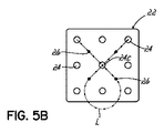
図1及び図2を参照して、プラットフォーム16は、プラットフォーム16上に取り外し可能に載置され得て流体ディスペンシングシステム10の較正に使用される、基準タイルとして言及された、外部ターゲットタイル22を収容するように構成された較正ステーション20を含んでいる。図示の実施形態では、基準タイル22は、平坦状であり、全体に正方形を有している。付加的に、基準タイル22は、少なくとも1つの、好適には少なくとも8個の、その上に印刷された外部参照点24を含んでいる。それらは、「基準」または「ターゲット」と呼ばれる。8個の基準24は、円形で、直径が2mmで等しいサイズであり、正方形ないし箱型パターンでタイル22上に等間隔であり、当該正方形ないし箱型パターンの任意の1つの側辺が等距離の間隔で位置決めされた3つの基準24を含んでいる。一実施形態では、図示のように、ターゲットタイル22が付加的に中央に位置決された基準24cを含み得て、タイル22は3−3グリッドパターンに配置された合計で9個の基準を含んでいる。中央の基準24cは、以下に説明される較正ルーチン29の初期セットアップ中に外側基準24の1つに対する代替物として利用され得て、較正ルーチン29の実際の実施にとっては必要ない。当業者は、ここで説明される較正方法を、任意の形状、サイズ、量、所望の間隔、の基準タイルないし基準に適用することができる。
1 and 2, platform 16 may be removably mounted on platform 16 and used to calibrate
図3は、本発明の一実施形態による、粘性のある流体のディスペンシングシステム10によって投与されるドットの載置位置を較正するために用いられる、自動ドット載置較正ルーチン29の簡略化バージョンを図示している。このドット載置較正ルーチン29において、コンピュータ11は、まず、工程30において、記憶された予備的なカメラ−ニードルのオフセット値にアクセスする。前述のように、カメラ−ニードルのオフセット値は、XY座標系における、流体ディスペンサ12のノズルの中心とビデオカメラ14の画像センサ(不図示)の中心との間の距離を表す2要素アレイである。流体ディスペンサ12とビデオカメラ14は、各々、XY平面内での互いの間の公知の距離を理想的に維持するべく、XYポジショナに取り付けられている。例えば、一実施形態では、流体ディスペンサ12とビデオカメラ14とは、XY平面内で互いに対して固定され得る。別の実施形態では、流体ディスペンサ12は、XY平面内でカメラ14に対して移動可能であり得て、ディスペンサ12とカメラ14の画像センサとの間に規定される距離は、計画的なもので、計測可能であり、繰り返し可能である。カメラ−ニードルのオフセット値、すなわち、流体ディスペンサ12とビデオカメラ14の画像センサとの間のXY距離は、ディスペンサ12が正確にカメラ14によって特定される位置に流体を投与することができるように、コンピュータ11によって考慮されなければならない。コンピュータ11内に記憶された予備的なカメラ−ニードルのオフセット値は、例えば、以前の較正サイクルからのカメラ−ニードルのオフセット値であり得て、あるいは、適切な計測が行われた後でユーザによってコンピュータ11に教示された値であり得る。予備的なオフセット値の計測は、例えば、コンピュータエイデッドデザイン(CAD)ソフトウェアを用いて行われ得る。
FIG. 3 shows a simplified version of an automatic dot
次に、工程31では、コンピュータ11が指令を出してカメラ14を移動させ、基準タイル22上の各基準24の位置を得る。工程31乃至工程33により、図4に示された詳細なルーチン39を参照して以下に詳述されるように、8個の異なるアプローチ方向の各々に関連付けられたエラーを考慮するために、カメラ14及び流体ディスペンサ12は、両方とも、XY平面内の異なる方向から各基準に接近する。工程32で、コンピュータ11が指令を出して流体ディスペンサ12を8個の外側基準24の各々の中心にまで移動させ、そこに粘性のある流体のドットを投与させる。ここで用いられるように、「中心」という用語は、参照される対象のXY平面内での幾何的な中心に言及しており、参照される対象の重心として知られている。例えば、基準24、そこに投与されたドット、流体ディスペンサ12のノズル、及び、カメラ14のレンズは、各々、XY平面内の幾何的な中心(重心)を有していて、それが、これら対象の任意の2つの間のXY距離を計算するために用いられる。幾何的な形状の重心は、容易に決定されるし、不規則で非幾何的な形状を有する投与ドットに対しても、その重心は、当業者であれば計算可能である。
Next, at
工程33では、コンピュータ11が指令を出して、カメラ14が基準タイル22上に投与された8個のドットの各々の位置を得る。
At
工程34では、コンピュータ11が、各基準24の位置を、対応する流体のドットが実際に投与された位置と、比較する。具体的には、各基準24に対して、コンピュータ11が、基準24の中心のXY座標とその対応する投与ドットの中心のXY座標との間の差を決定する。コンピュータ11は、これら8個の値の平均を決定して、その平均値を記憶する。これが、「ドットオフセットエラー値」と呼ばれる。
In
工程35では、コンピュータ11が、ドットオフセットエラー値を、コンピュータ11によって教示されているか知られている限界値と比較する。ドットオフセットエラー値が限界値よりも小さい場合、流体ディスペンシングシステム10は、十分なドット載置精度で動作していて、十分に較正されているとみなされ、較正ルーチンは終了する。ドットオフセットエラー値が限界値よりも小さくない場合、コンピュータ11は、システム10が十分なドット載置精度で動作していないことを認識する。従って、較正ルーチン29は終了しない。代わりに、コンピュータ11は、工程36で、システム10内の付加的なエラーを考慮するべく、カメラ−ニードルのオフセット値を再計算ないし調整する。コンピュータ11は、工程31で始まる前述の処理を繰り返して、ドット載置精度を改善する。カメラ−ニードルのオフセット値の調整は、図4を参照して以下に詳述される。従って、ここで説明される処理は、ドット載置エラー値が限界値より小さくなってドット載置精度が十分に改善されるまで、コンピュータ11が工程31乃至36を繰り返す、という反復処理である。
In step 35, computer 11 compares the dot offset error value to a threshold value taught by computer 11 or known. If the dot offset error value is less than the limit value, the
図4を参照して、図3の自動のドット載置較正ルーチンが、ルーチン39として、付加的な詳細と共に示されている。工程40で、コンピュータ11が、まず、図3を参照して前述されたように、予備的なカメラ−ニードルのオフセットアレイC2Nを設定する。工程41で、コンピュータ11が、上左基準24aと下右基準24bの位置を見出して当該コンピュータ11にこれらの位置を教示するように、ユーザに指示をする。コンピュータ11は、基準タイル22が正方形パターンで等間隔に8個の円形の外側基準24を含んでいることを理解するよう、プログラムされている。従って、教示された2つの参照基準24a、24bの位置に基づいて、コンピュータ11は、残存する基準24の予測される位置を決定し得る。当業者は、コンピュータ11が代替的な基準のパターン及び量をも理解するようにプログラムされ得ることを、認識するであろう。
Referring to FIG. 4, the automatic dot placement calibration routine of FIG. 3 is shown as routine 39 with additional details. At
工程42で、コンピュータ11は指令を出して、それらの予測位置に基づいてカメラ14が8個の全ての基準24の位置を得る。カメラ14は、前述のように、各基準24の予測位置に、異なる方向から接近する。具体的には、図5Aの実施形態に示されるように、カメラ14は、4つの基本方位及びそれらの4つの組合せの各々から接近する。ここで用いられているように、「基本方位」という用語は、XY平面内での、北、東、南、西の方向に言及しており、図5Aでは、それぞれ、N、E、S、Wで示されている。それらの組合せは、北東、南東、南西、北西の方向を含んでおり、図5Aでは、それぞれ、NE、SE、SW、NWで示されている。XY平面内で基準タイル22上に位置決めされた基準24に対して、北は、基準タイル22の上縁22aに対応しており、東は、右縁22bに対応しており、南は、下縁22cに対応しており、西は、左縁22dに対応している。
At
図5Aに示されるように、カメラ14は、基準タイル22の中心の近くの位置で始動して、南西方向から第1基準24に接近し、東方向から第2基準24に接近し、南東方向から第3基準24に接近し、北方向から第4基準24に接近し、北東方向から第5基準24に接近し、西方向から第6基準24に接近し、北西方向から第7基準24に接近し、南方向から第8基準24に接近する。カメラが各基準24に位置する時、エンコーダ(不図示)が用いられて基準24の中心のXY座標(値)を記録する。かくして、8個の全ての基準24のXY座標が、コンピュータ11によって「基板基準位置」アレイVsfとして記憶される。当業者は、接近の方向が任意の所望の方向及びその組合せを含んで、接近の方向が任意の所望の数の基準を考慮する、というように、ここで説明される較正方向を適用し得る。
As shown in FIG. 5A, the
図5Aに示されるように、カメラ14が移動する結果的な経路は、基準タイル22の中心回りに略90°の増分で等間隔の4つの円弧状脚部Lを有する曲線形状を規定している。基本方位及びそれらの組合せの各々から8個の基準24に接近することは、移動方向に依存した運動に起因して流体ディスペンシングシステム10が異なるエラーの大きさを示すために、有利である。当該エラーは、「方向性エラー」と呼ばれる。基準24または投与されたドットの位置取得の際の方向性エラーの影響は、かくして、XY平面内での流体ディスペンサ12及びビデオカメラ14の可能性ある複数の移動方向から基準24及び投与されたドットに接近することによって、最小化される。
As shown in FIG. 5A, the resulting path traveled by the
工程43で、コンピュータ11は指令を出して、流体ディスペンサ12が流体の一連のスタータードット26を基準タイル22上に投与する。スタータードット26は、ユーザによって規定されるサイズ、形状、量及びパターンである。図示の実施形態では、少なくとも1つの、好適には4つのスタータードット26が、基準タイル22の中心近くの正方形パターンを形成するべく、等間隔に投与される。当該スタータードット26は、図5Bに示されるように、基準24のいずれとも重複していない。スタータードット26を投与する時、流体ディスペンサ12は、北西方向から第1及び第2スタータードット26の位置に接近して、その後、南西方向から第3及び第4スタータードット26の位置に接近して、単一の円弧状脚部Lを有する曲線形状を規定する経路を移動する。一連のスタータードット26を投与することは、流体ディスペンサ12が「巻き上がる(spool-up)」または「ウォームアップする(warm-up)」ことを許容し、流体ディスペンサ12は、その後に投与されるドットのために、流体の正確な量を投与可能である。
At
工程44で、コンピュータ11が指令を出して、流体ディスペンサ12が粘性のある流体の較正ドット28を8個の基準24の各々の中心に投与する。図5Cに示されるように、流体ディスペンサ12は、前述の8個の基準24の各々の位置を得る時にカメラ14が移動したのと同じ経路を移動する。流体ディスペンサ12が各較正ドット28を投与する時、流体ディスペンサ12が当該較正ドット28を投与するために移動された位置のXY座標を記録するべく、エンコーダが利用される。8個の投与された較正ドット28の全ての投与位置のXY座標は、その後、コンピュータ11によって「投与時移動」アレイVmtとして記憶される。
At
工程45で、コンピュータ11は指令を出して、カメラ14が8個の投与された較正ドット28の各々の位置を得る。図5Cに示されるように、カメラ14は、工程44において流体ディスペンサ12が移動したのと同じで、工程42においてカメラ14が移動したのと同じである経路を移動する。カメラ14が各投与較正ドット28の位置を得る時、当該較正ドット28の中心のXY座標を記録するために、エンコーダが用いられる。各投与較正ドット28のXY座標は、その後、コンピュータ11によって「見出された較正ドット」アレイVcdとして記憶される。
At step 45, the computer 11 commands the
工程46で、コンピュータ11は、各投与較正ドット28のために、投与較正ドット28の中心の位置を、その対応の基準24の中心の位置に対して比較することで、「ドットオフセットエラー」を決定する。具体的には、コンピュータ11は、基板基準位置アレイVsfと見出された較正ドットアレイVcdとの間の差分を取ることで、ドットオフセットエラーアレイVdoe を計算して記憶する。これは、次のように表される。
Vdoe = Vsf − Vcd
At step 46, the computer 11 compares, for each
V doe = V sf − V cd
工程47で、コンピュータ11は、ドットオフセットエラーアレイVdoe の大きさを計算することによって、「ドットオフセットマグニチュード」アレイVdom を計算して記憶する。これは、次のように表される。
Vdom = sqrt(Vdoe[x]2 + Vdoe[y]2)
At step 47, computer 11 calculates and stores the "dot offset magnitude" array V dom by calculating the size of the dot offset error array V doe . This is expressed as follows.
V dom = sqrt (V doe [x] 2 + V doe [y] 2 )
工程48で、コンピュータ11は、各投与較正ドット28のために、その中心が、その対応の基準24の中心に対してオフセットされている(ずれている)方向を見出すことによって、「ドットオフセット方向」アレイVdod を決定する。
At
工程49で、コンピュータ11は、ドットオフセットマグニチュードアレイVdom 内に記憶された個々の値の平均を計算することによって、「平均ドットオフセットマグニチュード」値を決定する。コンピュータ11は、その後、この平均ドットオフセットマグニチュード値が、コンピュータ11によって教示されるか知られている受容可能な閾値ないし限界値より小さいか否か、を決定する。受容可能な限界値は、ユーザによって規定され得て、コンピュータ11に通信され得る。図3に関して前述したように、平均ドットオフセットエラー値が受容可能な限界値よりも小さいなら、その時、較正ルーチン39は終了される。平均ドットオフセットエラー値が受容可能な限界値よりも小さくないなら、その時、較正ルーチン39は継続して、予備的なカメラ−ニードルのオフセット値によって考慮されていないエラー源に対処すべくカメラ−ニードルのオフセット値を再計算ないし調整して、最終的にドット載置精度を改良することに向けられた工程に進む。 At step 49, the computer 11 determines an "average dot offset magnitude" value by calculating the average of the individual values stored in the dot offset magnitude array V dom . The computer 11 then determines whether this average dot offset magnitude value is less than an acceptable threshold or limit value taught or known by the computer 11. Acceptable limits may be defined by the user and communicated to computer 11. As described above with respect to FIG. 3, if the average dot offset error value is less than the acceptable limit value, then the calibration routine 39 is exited. If the average dot offset error value is not less than the acceptable limit, then the calibration routine 39 continues with the camera-needle to account for error sources not considered by the preliminary camera-needle offset value. Finally, the process proceeds to a process directed to improving the dot placement accuracy by recalculating or adjusting the offset value of.
後者の場合において、工程50で、コンピュータ11は、各投与較正ドット28のために、流体ディスペンサ12が較正ドット28を投与するために移動された位置を投与ドット28が実際にカメラ14によって見出された位置と比較することによって、局所的なカメラ−ニードルのオフセット値を決定する。具体的には、コンピュータ11は、投与時移動アレイVmtと見出だされた較正ドット基準アレイVcdとの間の差を計算することによって、「局所的なカメラ−ニードルのオフセット値」アレイVloを計算して記憶する。これは、次のように表される。
Vlo = Vmt − Vcd
In the latter case, at
V lo = V mt − V cd
工程51で、コンピュータ11は、各投与較正ドット28のために、ディスペンサ12が較正ドット28を投与するために移動するよう指令された位置を流体ディスペンサ12が較正ドット28を投与するために実際に移動した位置と比較することによって、「指令vs実際」エラー値を決定する。具体的には、コンピュータ11は、投与時移動アレイVmt、基板基準位置アレイVsf、予備的なカメラ−ニードルのオフセットアレイC2Nの間の差を計算することによって、「指令vs実際エラー」アレイVcaを計算して記憶する。これは、次のように表される。
Vca = Vmt − Vsf − C2N
At
V ca = V mt − V sf − C2N
工程52で、コンピュータ11は、各投与較正ドット28のために、与えられた投与較正ドット28と関連する局所的なカメラ−ニードルのオフセット値と指令vs実際エラー値との両方を考慮した、調整されたカメラ−ニードルのオフセット値を計算することによって、新しいカメラ−ニードルのオフセット値を計算する。具体的には、コンピュータ11は、局所的なカメラ−ニードルのオフセットアレイVloと指令vs実際エラーアレイVcaとの和を計算することによって、「調整カメラ−ニードルのオフセット」アレイVc2nを計算して記憶する。これは、次のように表される。
Vc2n = Vlo + Vca
コンピュータ11は、次に、調整カメラ−ニードルのオフセットアレイVc2n内に記憶された個々の値の平均を計算することによって、新しいカメラ−ニードルのオフセットアレイC2Nを計算する。これは、次のように表される。
C2N = average(Vc2n[i])
新しい、調整カメラ−ニードルのオフセットは、従って、予備的なカメラ−ニードルのオフセットによって考慮されていなかった流体ディスペンシングシステム10のエラー源を考慮するものである。従って、この新しいカメラ−ニードルのオフセットが、引き続いてのドット投与サイクルの間、ドットオフセットエラーを低減してドット載置精度を改善するべく、システム10に適用され得る。
At
V c2n = V lo + V ca
The computer 11 then adjusts the camera - by calculating the mean of the individual values stored in the offset array V c2n needle, new camera - calculating the offset array C2N needle. This is expressed as follows.
C2N = average (V c2n [i])
The new adjustment camera-needle offset thus takes into account the error source of the
工程53で、コンピュータ11は、較正ルーチン39の追加の反復が実施され得るように、基準タイル22を清掃することをユーザに促す。
At
工程54で、コンピュータ11は、較正ルーチン39が、ユーザが規定する脱出用の値(escape value)を超える反復回数だけ実施されたか否かを決定する。実施された反復回数が脱出用の値を超えていない場合、ルーチン39の更なる反復が実施され、工程42で始まる。実施された反復回数が脱出用の値を超えている場合、コンピュータ11は工程55に進み、そこでコンピュータ11は、ユーザに、ルーチン39の追加の反復が所望されるか否かを示すことを促す。追加の反復が所望されないなら、較正ルーチン39は終了されて、追加の反復は実施されない。追加の反復が所望されるなら、コンピュータ11はルーチン39の追加の反復のために工程42に戻る。
At step 54, the computer 11 determines whether the calibration routine 39 has been performed a number of iterations exceeding the user defined escape value. If the number of iterations performed does not exceed the exit value, then a further iteration of routine 39 is performed, beginning at
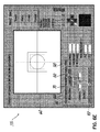
図6A乃至図6Gを参照して、例えばルーチン39のようなドット載置較正の一実施形態は、グラフィカルユーザインタフェース(GUI)59を含む。それを介して、ユーザは、ルーチン39と相互作用(インタラクト)し得る。GUI59は、ビューファインダ60を有しており、そこにコンピュータ11は、カメラによって特定された基準24及び投与ドット28を表示する。図6A乃至図6Gは、例えばパーソナルコンピュータであり得るコンピュータ11から撮られた一連のスクリーンショットを示しており、GUI59とのユーザの相互作用の様々な段階を図示している。
With reference to FIGS. 6A-6G, one embodiment of a dot placement calibration, such as routine 39, includes a graphical user interface (GUI) 59. The graphical user interface (GUI) 59 of FIG. Through it, the user can interact with the routine 39. The
ユーザは、例えばコンピュータ11のRUN>SETUPスクリーンでルーチン39を選択することによって、較正ルーチン39を開始する。GUI59は、この時、コンピュータ11上で表示し、ユーザは最初に「Main」(メイン)タブ61に向けられる。ユーザは、次に、カメラ14をXY面内の所望の位置に移動させる。そこで、流体ディスペンシングシステム10は、ドット28の投与前の流体ディスペンサ12のノズルの基準タイル22に対するZ方向の高さを測定するであろう。このXY位置は、「高さ検出位置」として参照され、基準タイル22へのドット28の投与のためにZ軸に沿って下方位置に向けて流体ディスペンサ12を移動させるように指令する時、コンピュータ11によって考慮される。この高さは、例えばレーザや機械的測定装置のような任意の好適な装置(不図示)を用いて、測定され得る。図6Aに示されるように、ユーザは、次に、「Teach HS location」(HS位置の教示)62を選択して、較正ルーチン39を作動させているコンピュータ11に高さ検出位置を教示する。ユーザは、次に、「For Fiducials」(基準用)64を選択して、ルーチン39が基準24を見出すために用いるパラメータを設定する。
The user initiates the calibration routine 39, for example by selecting the routine 39 on the RUN> SETUP screen of the computer 11. The
図6Bを参照して、ユーザは、次に、「Status」(ステータス)タブ66を選択して、「Max Acceptable Error」(最大許容エラー)68を規定する。それは、成功の判断基準としてルーチン39によって用いられる最大ドットオフセットエラーを設定するものである。 Referring to FIG. 6B, the user then selects the “Status” tab 66 to define a “Max Acceptable Error” 68. It sets the maximum dot offset error used by the routine 39 as a success criterion.
図6Cを参照して、ユーザは、次に、「Dot Finder」(ドットファインダー)タブ70を選択して、Search Window(サーチウィンドウ)72、Camera Setting Time(カメラ設定時間)74、及び、Acceptable Threshold(許容閾値)76を、基準24のために規定する。Dot color(ドット色)78は、ルーチン39の結果に影響しない。
Referring to FIG. 6C, the user next selects the “Dot Finder” (dot finder)
図6Dを参照して、ユーザは、次に、「Parameters」(パラメータ)タブ80を選択して、基準24の位置を得るために用いられるパラメータ82〜96を設定する。Dark/Light Threshold(暗い/明るい閾値)82は、カメラ14によって特定された基準24や投与ドット28の円の縁部に対応するグレイ色の影を規定する。図示の実施形態では、Dark/Light Threshold82の零の値が、黒色に対応しており、255の値が、白色に対応している。従って、基準24が白色の円としてカメラ14によって特定されるなら、約200の値が入力されるべきである。基準24が黒色の円として特定されるなら、約80の値が入力されるべきである。Restrict Min Diameter(最小直径の制限)84及びRestrict Max Diameter(最大直径の制限)86は、ルーチン39によって操作されるカメラ14によって特定可能な円の最小直径及び最大直径を制限するものである。これらのパラメータ84、86は、複数の円がカメラ14によって特定されてビューファインダ60内に表示される時、「悪い」円を排除(filter out)するべく利用される。これらのパラメータ84、86のために入力される値は、ビューファインダ60内でコンピュータ11によって線引きされる外側ボックス87及び内側ボックス88の幅を制御する。この態様では、外側ボックス87の幅が、Restrict Max Diameter86のために入力された値に対応しており、内側ボックス88の幅が、Restrict Min Diameter84のために入力された値に対応している。これらのパラメータ84、86のために入力される値に関連する単位は、ピクセル(画素)である。
Referring to FIG. 6D, the user then selects the “Parameters”
更に図6Dを参照して、Roundness(真円度)89が、カメラ14によって特定される基準24または較正ドット28の円の予想される真円度に対応している。例えば、完全な円が、Roundness88の100%の値に対応しており、不定形の塊が、Roundness88の0%の値に対応している。良好な円形の円がほぼ確実に特定されると予想される場合、約90%の値が入力されるべきである。Circumference Points(周辺点)90は、基準24や投与ドット28のような特定された円について視認できる程度に対応している。例えば、全円は100%の値に対応しており、半円は50%の値に対応している。全円がほぼ確実に特定されると予想される場合、約90%の値が入力されるべきである。
Still referring to FIG. 6D, the
更に図6Dを参照して、Fail if Multiple Dots Found(複数ドット発見の場合は失敗)92、Find Dot Nearest Center(中心に最も近いドットを見出す)94、及び、Find Largest Dot(最大ドットを見出す)96は、それぞれ、Restrict Min Diameter84、Restrict Max Diameter86、Roundness88、Circumference Points90といったパラメータを複数の特定された円が満たす場合に、ルーチン39を実施するコンピュータ11によって取られる動作を規定している。Fail if Multiple Dots Found92は、まるで基準24が見出されなかったようにコンピュータ11が動作することに帰結する。Find Dot Nearest Center94、及び、Find Largest Dot96は、それぞれ、ユーザに何かを促すことなく、前述のようにコンピュータ11が動作することに帰結する。
Still referring to FIG. 6D, Fail if Multiple Dots Found (fail in the case of multiple dot discovery) 92, Find Dot Nearest Center (find dot closest to center) 94, and Find Largest Dot (find largest dot). 96 define the actions taken by the computer 11 implementing the routine 39 if a plurality of identified circles satisfy parameters such as Restrict
図6Eを参照して、ユーザは、次に、基準24がビューファインダ60に示されている間に、ルーチン39が適切に基準24を特定することができるか否かを決定すべく、「Test」(テスト)タブ98を選択する。「Test」ボタン100は、好適には、同一の基準24に対して複数回選択されて、複数の実施を模倣(シミュレート)するべく、少なくとも1つの他の基準に対しても付加的に選択される。「Test」ボタン100の選択が間違った円を強調する場合、ユーザは、次に、以前のタブ66、70、80に戻って、適切なパラメータを調整して、それから適切な動作を保証するべく「Test」タブ98に戻るべきである。テストが一旦満たされると、ユーザは、次に、「Save Light Levels」(光レベル保存)101を選択して、基準24を特定するために用いられた設定を保存(save)する。
Referring to FIG. 6E, the user can then “Test” to determine whether routine 39 can properly identify fiducial 24 while fiducial 24 is shown in
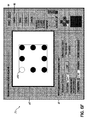
図6Aに戻って、ユーザは、次に、「For Dots」(ドット用)110を選択して、ルーチン39の間に投与ドット28を特定するために用いられるパラメータを設定する。ユーザは、ビューファインダ60内で基準24の中心の位置決めをして、「Dispens dot at current location」(現在位置でのドット投与)112を選択する。これは、流体ディスペンサ12に、単一ドット28の投与を指令する。それは、Dot Finder(ドットファインダ)70のパラメータを設定するために用いられ得る。ユーザは、次に、対象として基準24ではなくて投与ドット28を用いて、前述の工程を繰り返す。投与ドットの設定がなされて保存されると、ユーザは、次に、「Next」ボタン114を選択する。
Returning to FIG. 6A, the user then selects “For Dots” (for dots) 110 to set the parameters used to identify the
図6Fに戻って、メインタブ61において、ルーチン39は、ユーザに、第1の上左基準24aの位置を得ることを促す。ユーザは、継続のため「Next」114を選択する。ユーザは、次に、ビューファインダ60内で上左基準24aを位置決めして、「Teach」(教示)116を選択する。これにより、コンピュータ11は、上左基準24aのXY座標を保存する。
Returning to FIG. 6F, at main tab 61, routine 39 prompts the user to obtain the position of first upper
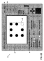
図6Gを参照して、ルーチン39は、ユーザに、第2の下右基準24bの位置を得ることを促す。ユーザは、継続のため「Next」114を選択する。ユーザは、次に、ビューファインダ60内で下右基準24bを位置決めして、「Teach」(教示)116を選択する。これにより、コンピュータ11は、下右基準24bのXY座標を保存する。図3乃至図5Cを参照して前述された工程を用いることで、ルーチン39は、8個の全ての基準24の位置を得て、各基準24の中心に較正ドット28を投与し、投与された較正ドット28の位置を得て、ドットオフセットエラーを計算する。ドットオフセットエラーが、ユーザ規定の限界値より大きい場合、「・・・という値の平均ドットオフセットマグニチュードが、・・・インチという許容閾値を超えています」のようなメッセージを表示することによって、ポップアップエラーウィンドウ(不図示)がユーザに警告をする。ユーザは、「OK」ボタン(不図示)を選択することによって当該メッセージを承認し、基準タイル22を拭って清浄にして、「Next」114を選択する。ルーチン39は、流体ディスペンシングシステムのドット載置精度を改善するべく、前述の工程を繰り返し得る。新しいドットオフセットエラーがユーザ規定の限界値よりも小さい場合、ルーチン39は成功であり、その結果を表示するポップアップウィンドウ(不図示)が現れるであろう。このポップアップウィンドウは、例えば「バルブ−カメラオフセット=([xの値]、[yの値])インチ。受容可能なドットオフセットエラー=[値]インチ。平均ドットオフセットエラー=[値]インチ。」のようなメッセージを含み得る。ユーザは、「OK」ボタンを選択することによって当該メッセージを承認し、「Done」ボタンを選択することによってルーチン39を終了する。
Referring to FIG. 6G, the routine 39 prompts the user to obtain the position of the second lower
前述の較正ルーチン39及びGUI59は、任意の好適な形状、量(数)及び形態の基準を有する基準タイルとの使用のために、当業者によって、必要に応じて修正され得る。
The calibration routine 39 and
本発明は、特定の実施形態についての記述によって説明され、当該実施形態は、かなり詳しく説明された。しかしながら、添付の特許請求の範囲の請求項の範囲を、そのような詳細に制限することや、何らかの態様で限定することは、意図されていない。ここで説明された様々な特徴は、単独でも、任意の組合せでも、利用可能である。付加的な利点及び修正は、当業者にとって容易である。本発明は、その広い観点では、特定の詳細や代表的な装置及び方法や図示の例に限定されない。従って、本発明の概念の範囲または精神から逸脱することなく、そのような詳細からの発展がなされ得る。 The invention has been described by a description of particular embodiments, which have been described in considerable detail. However, it is not intended to limit the scope of the appended claims to such details or to limit the scope in any manner. The various features described herein may be used alone or in any combination. Additional advantages and modifications are easy for the person skilled in the art. The invention, in its broader aspects, is not limited to the specific details, representative apparatus and method, and illustrated example. Accordingly, departures may be made from such details without departing from the scope or spirit of the inventive concept.
Claims (8)
(0)光学センサ−流体ディスペンサのオフセットを記憶する工程と、
(i)前記光学センサを用いて複数の外部参照点の位置を得る工程と、
(ii)前記流体ディスペンサを前記複数の外部参照点まで移動させる工程と、
(iii)前記流体ディスペンサを用いて前記ノズルから前記複数の外部参照点の各々に流体を投与する工程と、
(iv)前記光学センサを用いて投与された流体の位置を得る工程と、
(v)前記複数の外部参照点の各々について、当該外部参照点の位置と前記投与された流体の位置との間の距離を計算する工程と、
(vi)前記計算された複数の距離に基づいてある値を計算し、当該値が上限値よりも大きいことを判定すると、それに応じて前記光学センサ−流体ディスペンサのオフセットを調整する工程と、
(vii)少なくとも部分的に前記計算された複数の距離及び前記調整された光学センサ−流体ディスペンサのオフセットに基づいて訂正値を決定する工程と、
(viii)前記訂正値を用いて投与される流体の載置精度を改良する工程と、
を備えたことを特徴とする方法。 A method of calibrating a fluid dispensing system comprising a fluid dispenser having a nozzle and an optical sensor, comprising:
(0) storing the offset of the optical sensor-fluid dispenser;
(I) obtaining positions of a plurality of external reference points using the optical sensor;
(Ii) moving the fluid dispenser to the plurality of external reference points;
(Iii) dispensing fluid from the nozzle to each of the plurality of external reference points using the fluid dispenser;
(Iv) obtaining the position of the administered fluid using the optical sensor;
(V) calculating, for each of the plurality of external reference points, the distance between the position of the external reference point and the position of the dispensed fluid;
(Vi) calculating a value based on the calculated plurality of distances, and adjusting the optical sensor-fluid dispenser offset accordingly if it is determined that the value is greater than the upper limit value;
(Vii) determining a correction value based at least in part on the calculated plurality of distances and the adjusted optical sensor-fluid dispenser offset;
(Viii) improving the placement accuracy of the fluid to be administered using the correction value;
A method characterized in that it comprises.
前記ある値は、前記複数の外部参照点の各々に対応する計算された距離を平均化することによって得られる
ことを特徴とする請求項1に記載の方法。 The plurality of external reference points are positioned on the tile,
The method according to claim 1, wherein the certain value is obtained by averaging calculated distances corresponding to each of the plurality of external reference points.
ことを特徴とする請求項2に記載の方法。 The method of claim 2, wherein the tile has at least eight external reference points.
距離を計算する前記工程は、更に、前記外部参照点の重心及び前記投与された流体の重心の間の距離を計算する工程を含んでいる
ことを特徴とする請求項1に記載の方法。 Each of the plurality of external reference points and the dispensed fluid has a center of gravity,
The method according to claim 1, wherein the step of calculating the distance further comprises the step of calculating the distance between the center of gravity of the external reference point and the center of gravity of the dispensed fluid.
ことを特徴とする請求項4に記載の方法。 5. The method of claim 4, wherein the fluid to be administered further comprises a drop of the fluid for each of the plurality of external reference points.
ことを特徴とする請求項1に記載の方法。 The method according to claim 1, wherein the steps (0) to (viii) are performed automatically by a controller.
を更に備えたことを特徴とする請求項1に記載の方法。 The method according to claim 1, further comprising repeating steps (0) to (vi) at least once before proceeding to steps (vii) and (viii).
を更に備えたことを特徴とする請求項7に記載の方法。 The method further comprises the step of repeating the steps (0) to (vi) until the certain value becomes smaller than the upper limit value before proceeding to the steps (vii) and (viii). The method described in 7.
Applications Claiming Priority (5)
| Application Number | Priority Date | Filing Date | Title |
|---|---|---|---|
| US201361921850P | 2013-12-30 | 2013-12-30 | |
| US61/921,850 | 2013-12-30 | ||
| US14/560,032 | 2014-12-04 | ||
| US14/560,032 US10082417B2 (en) | 2013-12-30 | 2014-12-04 | Calibration methods for a viscous fluid dispensing system |
| PCT/US2014/069263 WO2015102821A1 (en) | 2013-12-30 | 2014-12-09 | Calibration methods for a viscous fluid dispensing system |
Publications (3)
| Publication Number | Publication Date |
|---|---|
| JP2017512120A JP2017512120A (en) | 2017-05-18 |
| JP2017512120A5 JP2017512120A5 (en) | 2017-12-28 |
| JP6549131B2 true JP6549131B2 (en) | 2019-07-24 |
Family
ID=53481317
Family Applications (1)
| Application Number | Title | Priority Date | Filing Date |
|---|---|---|---|
| JP2016544078A Active JP6549131B2 (en) | 2013-12-30 | 2014-12-09 | Calibration method for viscous fluid dispensing system |
Country Status (6)
| Country | Link |
|---|---|
| US (1) | US10082417B2 (en) |
| JP (1) | JP6549131B2 (en) |
| KR (1) | KR20160105479A (en) |
| CN (1) | CN105849658B (en) |
| DE (1) | DE112014006090T5 (en) |
| WO (1) | WO2015102821A1 (en) |
Families Citing this family (4)
| Publication number | Priority date | Publication date | Assignee | Title |
|---|---|---|---|---|
| US9815081B2 (en) | 2015-02-24 | 2017-11-14 | Illinois Tool Works Inc. | Method of calibrating a dispenser |
| US10881005B2 (en) * | 2016-06-08 | 2020-12-29 | Nordson Corporation | Methods for dispensing a liquid or viscous material onto a substrate |
| JP6970697B2 (en) * | 2016-06-30 | 2021-11-24 | ベックマン コールター, インコーポレイテッド | Material dispensing evaluation system |
| CN108876859B (en) * | 2018-04-28 | 2022-06-07 | 苏州赛腾精密电子股份有限公司 | Calibration method, device, equipment and medium of dispenser |
Family Cites Families (37)
| Publication number | Priority date | Publication date | Assignee | Title |
|---|---|---|---|---|
| US224180A (en) * | 1880-02-03 | Bag-tie | ||
| US4812666A (en) | 1987-09-17 | 1989-03-14 | Universal Instruments Corporation | Position feedback enhancement over a limited repositioning area for a moveable member |
| US5138868A (en) * | 1991-02-13 | 1992-08-18 | Pb Diagnostic Systems, Inc. | Calibration method for automated assay instrument |
| US6224180B1 (en) | 1997-02-21 | 2001-05-01 | Gerald Pham-Van-Diep | High speed jet soldering system |
| US6186609B1 (en) * | 1997-10-27 | 2001-02-13 | Taiwan Semiconductor Manufacturing Co., Ltd | Apparatus and method for dispensing ink on an object |
| SE9901253D0 (en) | 1999-04-08 | 1999-04-08 | Mydata Automation Ab | Dispensing assembly |
| SE0003647D0 (en) * | 2000-10-09 | 2000-10-09 | Mydata Automation Ab | Method, apparatus and use |
| CA2464682A1 (en) * | 2001-10-26 | 2003-05-01 | Sequenom, Inc. | Method and apparatus for high-throughput sample handling process line |
| JP3838964B2 (en) | 2002-03-13 | 2006-10-25 | 株式会社リコー | Functional element substrate manufacturing equipment |
| US6991825B2 (en) * | 2002-05-10 | 2006-01-31 | Asm Assembly Automation Ltd. | Dispensation of controlled quantities of material onto a substrate |
| JP4121014B2 (en) * | 2002-07-18 | 2008-07-16 | アスリートFa株式会社 | Needle position correction method and potting device |
| US6890050B2 (en) * | 2002-08-20 | 2005-05-10 | Palo Alto Research Center Incorporated | Method for the printing of homogeneous electronic material with a multi-ejector print head |
| KR100597041B1 (en) * | 2002-09-20 | 2006-07-04 | 에이에스엠엘 네델란즈 비.브이. | Device inspection method and apparatus |
| US20040148763A1 (en) | 2002-12-11 | 2004-08-05 | Peacock David S. | Dispensing system and method |
| CN100518954C (en) | 2003-05-23 | 2009-07-29 | 诺德森公司 | Method of spraying stickum onto substrate by utilizing non-contact mode dispenser |
| US20050001869A1 (en) | 2003-05-23 | 2005-01-06 | Nordson Corporation | Viscous material noncontact jetting system |
| EP1646502A1 (en) | 2003-07-10 | 2006-04-19 | Koninklijke Philips Electronics N.V. | Method and device for accurately positioning a pattern on a substrate |
| US20050079106A1 (en) * | 2003-10-10 | 2005-04-14 | Baker Rodney W. | Robotic filling device |
| JP2005246130A (en) * | 2004-03-01 | 2005-09-15 | Seiko Epson Corp | Droplet jetting device |
| US7708362B2 (en) * | 2004-04-21 | 2010-05-04 | Hewlett-Packard Development Company, L.P. | Printhead error compensation |
| US20060029724A1 (en) | 2004-08-06 | 2006-02-09 | Nordson Corporation | System for jetting phosphor for optical displays |
| CA2587747C (en) | 2004-11-15 | 2013-01-08 | Fibics Incorporated | System and method for focused ion beam data analysis |
| EP1866653A4 (en) * | 2005-03-07 | 2009-08-26 | Novx Systems Inc | Automated analyzer |
| EP1701231A1 (en) | 2005-03-08 | 2006-09-13 | Mydata Automation AB | Method of calibration |
| US20080006653A1 (en) * | 2006-03-13 | 2008-01-10 | Biomachines, Inc. | Small volume liquid handling system |
| KR100884834B1 (en) * | 2006-05-16 | 2009-02-20 | 주식회사 탑 엔지니어링 | Method for aligning substrate for paste dispenser |
| US7833572B2 (en) | 2007-06-01 | 2010-11-16 | Illinois Tool Works, Inc. | Method and apparatus for dispensing a viscous material on a substrate |
| JP4661840B2 (en) * | 2007-08-02 | 2011-03-30 | セイコーエプソン株式会社 | Alignment mask and dot position recognition method |
| US8765212B2 (en) | 2007-09-21 | 2014-07-01 | Nordson Corporation | Methods for continuously moving a fluid dispenser while dispensing amounts of a fluid material |
| US7531047B1 (en) * | 2007-12-12 | 2009-05-12 | Lexmark International, Inc. | Method of removing residue from a substrate after a DRIE process |
| JP2010117441A (en) * | 2008-11-11 | 2010-05-27 | Konica Minolta Holdings Inc | Alignment mask and method for measuring position of landing dot by using the same |
| JP2011222705A (en) * | 2010-04-08 | 2011-11-04 | Canon Inc | Method for manufacturing imprint device and imprint substrate |
| WO2012155267A1 (en) | 2011-05-13 | 2012-11-22 | Fibics Incorporated | Microscopy imaging method and system |
| JP2013237005A (en) * | 2012-05-15 | 2013-11-28 | Sumitomo Heavy Ind Ltd | Thin film forming device and adjusting method for thin film forming device |
| AU2013289898A1 (en) * | 2012-07-13 | 2015-01-22 | Roche Diagnostics Hematology, Inc. | Controlled dispensing of samples onto substrates |
| US8944001B2 (en) * | 2013-02-18 | 2015-02-03 | Nordson Corporation | Automated position locator for a height sensor in a dispensing system |
| US9374905B2 (en) * | 2013-09-30 | 2016-06-21 | Illinois Tool Works Inc. | Method and apparatus for automatically adjusting dispensing units of a dispenser |
-
2014
- 2014-12-04 US US14/560,032 patent/US10082417B2/en active Active
- 2014-12-09 CN CN201480071470.5A patent/CN105849658B/en active Active
- 2014-12-09 WO PCT/US2014/069263 patent/WO2015102821A1/en active Application Filing
- 2014-12-09 KR KR1020167020856A patent/KR20160105479A/en not_active Application Discontinuation
- 2014-12-09 JP JP2016544078A patent/JP6549131B2/en active Active
- 2014-12-09 DE DE112014006090.9T patent/DE112014006090T5/en active Pending
Also Published As
| Publication number | Publication date |
|---|---|
| CN105849658A (en) | 2016-08-10 |
| JP2017512120A (en) | 2017-05-18 |
| CN105849658B (en) | 2019-11-15 |
| WO2015102821A1 (en) | 2015-07-09 |
| DE112014006090T5 (en) | 2016-11-03 |
| KR20160105479A (en) | 2016-09-06 |
| US20150184996A1 (en) | 2015-07-02 |
| US10082417B2 (en) | 2018-09-25 |
Similar Documents
| Publication | Publication Date | Title |
|---|---|---|
| JP6549131B2 (en) | Calibration method for viscous fluid dispensing system | |
| US8944001B2 (en) | Automated position locator for a height sensor in a dispensing system | |
| EP3303991B1 (en) | Coordinate measuring machine with object location logic | |
| CN107498558A (en) | Full-automatic hand and eye calibrating method and device | |
| KR20100130204A (en) | Method and apparatus for dispensing material on a substrate | |
| KR20100027113A (en) | Method and apparatus for dispensing a viscous material on a substrate | |
| JP6487324B2 (en) | Supply system and method for supplying material based on angular location features | |
| CN106950917A (en) | Camera calibrated method and device | |
| JP2008260013A (en) | Paste coater and its control method | |
| CN104685974A (en) | Method of dispensing material based on edge detection | |
| CN113310443A (en) | Mechanical arm guided spraying calibration method, device, equipment and storage medium thereof | |
| JP6659732B2 (en) | How to calibrate a dispenser | |
| CN113534112B (en) | Laser height measurement calibration method for arc-shaped transparent workpiece | |
| JP6078316B2 (en) | Board work equipment | |
| CN104620685A (en) | Method and apparatus for calibrating dispensed deposits | |
| CN107079620A (en) | Fitting machine and used fitting machine electronic component absorption posture inspection method | |
| JP6868982B2 (en) | A method for mounting a semiconductor provided with a raised portion at a substrate position on a substrate. | |
| JPH0565229B2 (en) | ||
| JP2713687B2 (en) | Paste coating machine | |
| CN110012657A (en) | The transfer method and Related product of high-speed paster | |
| JPH09122554A (en) | Paste applying device | |
| CN114653510B (en) | Automatic ink coating method and device for side edges of AR (augmented reality) glasses lenses and related equipment | |
| CN209937962U (en) | Crystal silicon photovoltaic solar cell printing positioning platform calibration device | |
| CN106970025A (en) | A kind of camera mounting bracket vision correction system based on delivery platform | |
| KR100795510B1 (en) | Method for Inspecting Dispensing Position in Paste Dispenser |
Legal Events
| Date | Code | Title | Description |
|---|---|---|---|
| RD04 | Notification of resignation of power of attorney |
Free format text: JAPANESE INTERMEDIATE CODE: A7424 Effective date: 20170425 |
|
| A521 | Request for written amendment filed |
Free format text: JAPANESE INTERMEDIATE CODE: A523 Effective date: 20171116 |
|
| A621 | Written request for application examination |
Free format text: JAPANESE INTERMEDIATE CODE: A621 Effective date: 20171116 |
|
| A977 | Report on retrieval |
Free format text: JAPANESE INTERMEDIATE CODE: A971007 Effective date: 20180914 |
|
| A131 | Notification of reasons for refusal |
Free format text: JAPANESE INTERMEDIATE CODE: A131 Effective date: 20181001 |
|
| A521 | Request for written amendment filed |
Free format text: JAPANESE INTERMEDIATE CODE: A523 Effective date: 20181228 |
|
| A131 | Notification of reasons for refusal |
Free format text: JAPANESE INTERMEDIATE CODE: A131 Effective date: 20190516 |
|
| A521 | Request for written amendment filed |
Free format text: JAPANESE INTERMEDIATE CODE: A523 Effective date: 20190610 |
|
| TRDD | Decision of grant or rejection written | ||
| A01 | Written decision to grant a patent or to grant a registration (utility model) |
Free format text: JAPANESE INTERMEDIATE CODE: A01 Effective date: 20190620 |
|
| A61 | First payment of annual fees (during grant procedure) |
Free format text: JAPANESE INTERMEDIATE CODE: A61 Effective date: 20190626 |
|
| R150 | Certificate of patent or registration of utility model |
Ref document number: 6549131 Country of ref document: JP Free format text: JAPANESE INTERMEDIATE CODE: R150 |
|
| R250 | Receipt of annual fees |
Free format text: JAPANESE INTERMEDIATE CODE: R250 |
|
| R250 | Receipt of annual fees |
Free format text: JAPANESE INTERMEDIATE CODE: R250 |