JP6546554B2 - Power storage system - Google Patents
Power storage system Download PDFInfo
- Publication number
- JP6546554B2 JP6546554B2 JP2016058477A JP2016058477A JP6546554B2 JP 6546554 B2 JP6546554 B2 JP 6546554B2 JP 2016058477 A JP2016058477 A JP 2016058477A JP 2016058477 A JP2016058477 A JP 2016058477A JP 6546554 B2 JP6546554 B2 JP 6546554B2
- Authority
- JP
- Japan
- Prior art keywords
- storage
- charging
- charge
- discharge
- value
- Prior art date
- Legal status (The legal status is an assumption and is not a legal conclusion. Google has not performed a legal analysis and makes no representation as to the accuracy of the status listed.)
- Active
Links
Images


Classifications
-
- Y—GENERAL TAGGING OF NEW TECHNOLOGICAL DEVELOPMENTS; GENERAL TAGGING OF CROSS-SECTIONAL TECHNOLOGIES SPANNING OVER SEVERAL SECTIONS OF THE IPC; TECHNICAL SUBJECTS COVERED BY FORMER USPC CROSS-REFERENCE ART COLLECTIONS [XRACs] AND DIGESTS
- Y02—TECHNOLOGIES OR APPLICATIONS FOR MITIGATION OR ADAPTATION AGAINST CLIMATE CHANGE
- Y02E—REDUCTION OF GREENHOUSE GAS [GHG] EMISSIONS, RELATED TO ENERGY GENERATION, TRANSMISSION OR DISTRIBUTION
- Y02E60/00—Enabling technologies; Technologies with a potential or indirect contribution to GHG emissions mitigation
- Y02E60/10—Energy storage using batteries
Description
並列接続された複数の蓄電素子を備える蓄電システムに関する。 The present invention relates to a storage system including a plurality of storage elements connected in parallel.
二次電池や電気二重層キャパシタなどの蓄電素子を備える蓄電システムにおいて、負荷に対する電力出力を増加させるために、蓄電素子を並列に接続する構成が知られている。ここで、並列に接続された複数の蓄電素子の内部抵抗が、劣化などを原因として、互いに異なった値となることが考えられる。この場合、各蓄電素子に流れる電流量Inは、蓄電システムの出力電圧をVout、各蓄電素子の開放端電圧をVop、各蓄電素子の内部抵抗をRinとすると、In=(Vout−Vop)/Rinとなる。 DESCRIPTION OF RELATED ART In the electrical storage system provided with electrical storage elements, such as a secondary battery and an electrical double layer capacitor, in order to make the electric power output with respect to load increase, the structure which connects an electrical storage element in parallel is known. Here, it is conceivable that internal resistances of a plurality of storage elements connected in parallel have different values due to deterioration or the like. In this case, assuming that an output voltage of the storage system is Vout, an open end voltage of each storage element is Vop, and an internal resistance of each storage element is Rin, a current amount In flowing through each storage element is In = (Vout-Vop) / It will be Rin.
つまり、内部抵抗の逆比に応じて、各蓄電素子に流れる電流量が異なることになり、内部抵抗の小さな蓄電素子において、他の蓄電素子と比べて、大きな電流が流れることになる。このため、内部抵抗の小さな蓄電素子に流れる電流が許容上限値に達したり、他の蓄電素子より早く充電率(SOC: State of Charge)が下限値(例えば、0%)に達したりすることが考えられる。 That is, the amount of current flowing to each storage element differs according to the inverse ratio of the internal resistance, and a large current flows in the storage element having a small internal resistance as compared to other storage elements. Therefore, the current flowing to the storage element having a small internal resistance may reach the allowable upper limit, or the state of charge (SOC) may reach the lower limit (for example, 0%) earlier than the other storage elements. Conceivable.
そこで、蓄電素子が直列接続された直列蓄電素子群が並列接続された蓄電装置において、各直列蓄電素子群に対して、可変抵抗回路を直列接続することで、各直列蓄電素子群に流れる電流量を調整する構成が特許文献1に開示されている。
Therefore, in a storage device in which a series storage element group in which storage elements are connected in series is connected in parallel, a variable resistance circuit is connected in series to each series storage element group to measure the amount of current flowing in each series storage element
ここで、上記特許文献1に開示の構成では、並列接続された蓄電素子(以下、本明細書では、「直列蓄電素子群」を「蓄電素子」に含むものとする)に対して、可変抵抗回路を直列接続し、その可変抵抗回路を用いて、蓄電素子に流れる電流量を常に調整する構成としている。つまり、可変抵抗回路において、常に電力消費が発生することとなる。
Here, in the configuration disclosed in
本発明は、上記課題に鑑みて為されたものであり、充放電を行いながら、蓄電素子の各充電率を近づけることが可能な構成であって、さらに、可変抵抗回路における電力消費を低減することが可能な構成を提供することを主たる目的とする。 The present invention has been made in view of the above problems, and has a configuration capable of bringing the charging rates of storage elements closer to one another while performing charging and discharging, and further reducing power consumption in a variable resistance circuit. The main purpose is to provide a possible configuration.
本構成は、並列接続された複数の蓄電素子(C1,C2)を備える蓄電システム(10)であって、前記蓄電素子にそれぞれ直列接続され、抵抗値が可変である可変抵抗回路(R1,R2)と、前記蓄電システムの放電時において、全ての前記蓄電素子の充電率が第1所定値以上である場合、全ての前記可変抵抗回路の抵抗値を最小に設定するとともに、前記複数の蓄電素子のいずれかの充電率が前記第1所定値未満である場合、前記蓄電素子の充電率が小さいほど、その蓄電素子に対し小さな放電電流が流れるように、前記可変抵抗回路の抵抗値をそれぞれ設定する放電制御と、前記蓄電システムの充電時において、全ての前記蓄電素子の充電率が第2所定値以下である場合、全ての前記可変抵抗回路の抵抗値を最小に設定するとともに、前記複数の蓄電素子のいずれかの充電率が前記第2所定値より大きい場合、前記蓄電素子の充電率が大きいほど、その蓄電素子に対し小さな充電電流が流れるように、前記可変抵抗回路の抵抗値をそれぞれ設定する充電制御と、のうち少なくとも一方の制御を実施する制御部(50)と、を備えることを特徴とする。 This configuration is a storage system (10) including a plurality of storage elements (C1, C2) connected in parallel, and variable resistance circuits (R1, R2) connected in series to the storage elements and having variable resistance values. And setting the resistance value of all the variable resistance circuits to a minimum when the charging rate of all the storage elements is equal to or greater than a first predetermined value at the time of discharging the storage system, and the plurality of storage elements When one of the charging rates is less than the first predetermined value, the smaller the charging rate of the storage element is, the smaller the discharge current flows to the storage element, and the resistance value of the variable resistance circuit is set. Discharge control, and setting the resistance value of all the variable resistance circuits to a minimum when the charging rates of all the storage elements are equal to or less than a second predetermined value during charging of the storage system. When the charging rate of any of the plurality of storage elements is larger than the second predetermined value, the resistance of the variable resistance circuit is set such that a smaller charging current flows to the storage element as the charging rate of the storage element is larger. A control unit (50) for performing at least one control of charging control for setting each value is characterized.
上記構成によれば、蓄電システムの放電時において、複数の蓄電素子のいずれかの充電率が第1所定値未満である場合、蓄電素子に対し、充電率が小さいほど小さな放電電流が流れるように、可変抵抗回路の抵抗値が設定される。これにより、放電を行いながら、蓄電素子の充電率を近づけることが可能になる。また、全ての蓄電素子の充電率が第1所定値以上である場合、全ての可変抵抗回路が最低値に設定されるため、可変抵抗回路における電力消費を低減できる。 According to the above configuration, when the charge rate of any one of the plurality of storage elements is less than the first predetermined value during discharging of the storage system, a smaller discharge current flows to the storage element as the charge rate decreases. The resistance value of the variable resistance circuit is set. This makes it possible to approximate the charging rate of the storage element while discharging. In addition, when the charging rates of all the storage elements are equal to or greater than the first predetermined value, all the variable resistance circuits are set to the minimum value, so that power consumption in the variable resistance circuits can be reduced.
同様に、蓄電システムの充電時において、複数の蓄電素子のいずれかの充電率が第2所定値より大きい場合、蓄電素子に対し、充電率が大きいほど小さな充電電流が流れるように、可変抵抗回路の抵抗値が設定される。これにより、充電を行いながら、蓄電素子の充電率を近づけることが可能になる。また、全ての蓄電素子の充電率が第2所定値以下である場合、全ての可変抵抗回路が最低値に設定されるため、可変抵抗回路における電力消費を低減できる。 Similarly, at the time of charging of the storage system, when the charging rate of any one of the plurality of storage cells is larger than the second predetermined value, the variable resistance circuit flows such that a smaller charging current flows to the storage cell as the charging rate increases. The resistance value of is set. This makes it possible to approximate the charging rate of the storage element while performing charging. In addition, when the charging rates of all the storage elements are equal to or less than the second predetermined value, all the variable resistance circuits are set to the minimum value, and therefore power consumption in the variable resistance circuits can be reduced.
つまり、上記構成によれば、充放電を行いながら、蓄電素子の各充電率を近づけることが可能であるとともに、さらに、可変抵抗回路における電力消費を低減可能である。 That is, according to the above configuration, while performing charging and discharging, it is possible to approximate each charging rate of the storage element, and further, it is possible to reduce power consumption in the variable resistance circuit.
(第1実施形態)
図1に本実施形態の蓄電システムの電気的構成を示す。蓄電システム10は、組電池11を備えている。蓄電システム10は、具体的には、電気自動車やハイブリッド自動車などの車両に搭載され、車両に搭載されているモータなどの負荷100に対して組電池11から電力供給を実施する。また、蓄電システム10は、電源101から電力供給をされることで、組電池11に対する充電を実施する。なお、電源101は、具体的には、車両外部の商用電源や、車両に搭載されている発電機などである。
First Embodiment
FIG. 1 shows the electrical configuration of the storage system of the present embodiment. The
組電池11は、複数の電池セルC11〜C18が直列接続された電池群C1と、複数の電池セルC21〜C28が直列接続された電池群C2とを備え、電池群C1と電池群C2とは並列接続されている。電池群C1,C2には、電池群C1,C2をそれぞれ冷却する冷却装置21,22が設けられている。冷却装置21,22は、具体的には、冷却ファンである。本実施形態では、電池群C1,C2が「蓄電素子」に相当する。また、電池セルC11〜C18,C21〜C28は、それぞれリチウムイオン二次電池である。
The assembled
本実施形態では、電池群C1,C2には、それぞれ可変抵抗回路R1,R2が直列接続された上で、並列接続されている。可変抵抗回路R1,R2は、直列接続された複数の抵抗素子R11〜R15,R21〜R25と、その抵抗素子R11〜R15,R21〜R25にそれぞれ並列接続されたスイッチSW11〜SW15,SW21〜SW25から構成されている。 In the present embodiment, variable resistance circuits R1 and R2 are connected in series to battery groups C1 and C2, respectively, and then connected in parallel. The variable resistance circuits R1 and R2 are connected to a plurality of resistance elements R11 to R15 and R21 to R25 connected in series and switches SW11 to SW15 and SW21 to SW25 connected in parallel to the resistance elements R11 to R15 and R21 to R25, respectively. It is configured.
スイッチSW11〜SW15,SW21〜SW25は、それぞれ半導体スイッチング素子であり、より具体的には、MOS−FETである。スイッチSW11〜SW15,SW21〜SW25がオン状態とされると、並列接続された抵抗素子R11〜R15,R21〜R25に流れる電流が、スイッチSW11〜SW15,SW21〜SW25にバイパスして流れ、可変抵抗回路R1,R2の抵抗値が変化する。スイッチSW11〜SW15が全てオン状態にされることで、可変抵抗回路R1の抵抗値は最小値(略0)となり、スイッチSW21〜SW25が全てオン状態にされることで、可変抵抗回路R2の抵抗値は最小値(略0)となる。 The switches SW11 to SW15 and SW21 to SW25 are each a semiconductor switching element, and more specifically, a MOS-FET. When the switches SW11 to SW15 and SW21 to SW25 are turned on, the current flowing through the resistance elements R11 to R15 and R21 to R25 connected in parallel bypasses the switches SW11 to SW15 and SW21 to SW25, and the variable resistance The resistance values of the circuits R1 and R2 change. When all the switches SW11 to SW15 are turned on, the resistance value of the variable resistance circuit R1 becomes the minimum value (approximately 0), and when all the switches SW21 to SW25 are turned on, the resistance of the variable resistance circuit R2 The value is the minimum value (approximately 0).
また、蓄電システム10は、組電池11に流れる充放電電流Iを検出する電流センサ31、蓄電システム10の出力電圧Vを検出する電圧センサ32、電池群C1,C2の温度をそれぞれ検出する温度センサ41,42を備えている。各センサ31,32,41,42の出力は、制御部50に入力されている。電流センサ31は、例えば、ホール素子である。電圧センサ32は、例えば、電圧値をアナログ値からデジタル値に変換するアナログデジタルコンバータである。温度センサ41,42は、例えば、感温抵抗である。
In addition, the
制御部50は、各センサ31,32,41,42による検出値に基づいて、スイッチSW11〜SW15,SW21〜SW25のオンオフ制御を行うことで可変抵抗回路R1,R2の抵抗値を設定し、電池群C1,C2に流れる充放電電流I1,I2の調整を行う。また、制御部50は、冷却装置21,22の制御を行う。以下、制御部50による制御について説明を行う。
The
制御部50は、蓄電システム10の放電時において、電池群C1,C2の充電率SOC1,SOC2の両方が所定値(第1所定値)以上である場合、可変抵抗回路R1,R2の抵抗値をそれぞれ最小(略0)に設定する。さらに、制御部50は、蓄電システム10の放電時において、電池群C1,C2の充電率SOC1,SOC2の両方が所定値(第1所定値)未満である場合、充電率が小さい電池群ほど、その電池群に対して小さな放電電流が流れるように、可変抵抗回路R1,R2の抵抗値をそれぞれ設定する。より具体的には、例えば、充電率SOC1が20%、充電率SOC2が10%である場合に、電池群C1に流れる電流I1と電池群C2に流れる電流I2との比がI1:I2=2:1となるように、可変抵抗回路R1,R2の抵抗値をそれぞれ設定する。これにより、放電時において、充電率SOC1,SOC2をともに0%とすることが可能になる。なお、充電率とは、電池群C1,C2それぞれの満充電容量に対する現在の容量の比率のことである。
At the time of discharge of
また、蓄電システム10の充電時において、電池群C1,C2の充電率SOC1,SOC2の両方が所定値(第2所定値)以下である場合、可変抵抗回路R1,R2の抵抗値をそれぞれ最小(略0)に設定する。さらに、制御部50は、蓄電システム10の充電時において、電池群C1,C2の充電率SOC1,SOC2の両方が所定値(第2所定値)より大きい場合、充電率が大きい電池群ほど、その電池群に対し小さな充電電流が流れるように、前記可変抵抗回路R1,R2の抵抗値をそれぞれ設定する。より具体的には、例えば、充電率SOC1が80%、充電率SOC2が90%である場合に、電池群C1に流れる電流I1と電池群C2に流れる電流I2との比がI1:I2=2:1となるように、可変抵抗回路R1,R2の抵抗値をそれぞれ設定する。これにより、充電時において、充電率SOC1,SOC2をともに100%とすることが可能になる。
In addition, when both of charging rates SOC1 and SOC2 of battery groups C1 and C2 are equal to or less than a predetermined value (second predetermined value) during charging of
次に、図2〜4を用いて、各電池群C1,C2から放電することが許容される放電許容電力Wom1,Wom2、及び、各電池群C1,C2に対して充電することが許容される充電許容電力Wim1,Wim2について説明を行う。なお、電池群C1の放電許容電力Wom1及び充電許容電力Wim1の説明のみを行い、電池群C2の放電許容電力Wom2及び充電許容電力Wim2については、電池群C1の放電許容電力Wom1及び充電許容電力Wim1と同様であるため説明を省略する。 Next, using FIGS. 2 to 4, discharge allowable powers Wom1 and Wom2 that are permitted to be discharged from each battery group C1 and C2 and charging to each battery group C1 and C2 are permitted. The charge allowable power Wim1 and Wim2 will be described. Note that only the discharge allowable power Wom1 and the charge allowable power Wim1 of the battery group C1 will be described, and the discharge allowable power Wom2 and the charge allowable power Wim2 of the battery group C2 will be the discharge allowable power Wom1 and the charge allowable power Wim1 of the battery group C1. The description is omitted because it is the same as the above.
図2に電池群C1の端子間電圧CCV1と、充放電電流I1との関係を示す。充放電電流I1が0のとき、端子間電圧CCV1と開放端電圧OCV1とが一致する。 FIG. 2 shows the relationship between the inter-terminal voltage CCV1 of the battery group C1 and the charge / discharge current I1. When the charge / discharge current I1 is 0, the inter-terminal voltage CCV1 matches the open end voltage OCV1.
電池群C1から負荷100に対して放電が実施される場合、充放電電流I1が正の値になるとともに、端子間電圧CCV1において、電池群C1の内部抵抗Ri1と、充放電電流I1との積に相当する電圧分の電圧降下が生じる。ここで、充放電電流I1が所定値Th1に達すると、端子間電圧CCV1が、端子間電圧CCV1の下限値Vminとなる。ここで、下限値Vminは、具体的には、負荷100の動作下限電圧に基づいて設定されている値である。図2に示す領域(a)が、放電許容電力Wom1に相当し、Wom1=Vmin・Th1である。
When discharging from battery group C1 to load 100, charge / discharge current I1 becomes a positive value, and at terminal voltage CCV1, the product of internal resistance Ri1 of battery group C1 and charge / discharge current I1. A voltage drop corresponding to the voltage occurs. Here, when the charge / discharge current I1 reaches the predetermined value Th1, the inter-terminal voltage CCV1 becomes the lower limit value Vmin of the inter-terminal voltage CCV1. Here, specifically, the lower limit value Vmin is a value set based on the operation lower limit voltage of the
ここで、電池群C1の内部抵抗Ri1は、充電率SOC1及び温度T1に応じて定まる値である。電池群C1の開放端電圧OCV1は、充電率SOC1に応じて定まる値である。所定値Th1は、内部抵抗Ri1と、開放端電圧OCV1と、下限値Vminとに応じて定まる値である(Th1=(OCV1−Vmin)/Ri1)。このため、放電許容電力Wom1は、充電率SOC1及び温度T1に応じて定まる値である。 Here, the internal resistance Ri1 of the battery group C1 is a value determined according to the charging rate SOC1 and the temperature T1. The open end voltage OCV1 of the battery group C1 is a value determined according to the charging rate SOC1. The predetermined value Th1 is a value determined according to the internal resistance Ri1, the open end voltage OCV1, and the lower limit value Vmin (Th1 = (OCV1−Vmin) / Ri1). Therefore, discharge allowable power Wom1 is a value determined according to charging rate SOC1 and temperature T1.
図3に放電許容電力Wom1と、充電率SOC1及び温度T1との関係を表す図を示す。充電率SOC1の減少に応じて、開放端電圧OCV1が低下することで、放電許容電力Wom1は減少する。また、温度T1の低下に応じて、内部抵抗Ri1が増加することで、放電許容電力Wom1は減少する。 FIG. 3 is a diagram showing the relationship between discharge allowable power Wom1, charging rate SOC1 and temperature T1. As open-circuit voltage OCV1 decreases in accordance with the decrease in charging rate SOC1, discharge allowable power Wom1 decreases. Further, as the internal resistance Ri1 increases according to the decrease in the temperature T1, the discharge allowable power Wom1 decreases.
図2の説明に戻り、電池群C1から電源101から充電が実施される場合、充放電電流I1が負の値になるとともに、端子間電圧CCV1において、電池群C1の内部抵抗Ri1と、充放電電流I1との積に相当する電圧分の電圧上昇が生じる。ここで、充放電電流I1が所定値Th2に達すると、端子間電圧CCV1が、端子間電圧CCV1の上限値Vmaxとなる。ここで、上限値Vmaxは、具体的には、負荷100の動作上限電圧に基づいて設定されている値である。図2に示す領域(b)が、充電許容電力Wim1に相当し、Wim1=OCV1・Th2である。
Returning to the explanation of FIG. 2, when charging is performed from the battery group C1 to the
放電許容電力Wom1と同様に、同充電許容電力Wim1は、充電率SOC1及び温度T1に応じて定まる値である。即ち、電池群C1の内部抵抗Ri1は、充電率SOC1及び温度T1に応じて定まる値である。電池群C1の開放端電圧OCV1は、充電率SOC1に応じて定まる値である。所定値Th2は、内部抵抗Ri1と、開放端電圧OCV1と、上限値Vmaxとに応じて定まる値である(Th2=(Vmax−OCV1)/Ri1)。 Similar to the discharge allowable power Wom1, the charge allowable power Wim1 is a value determined according to the charge ratio SOC1 and the temperature T1. That is, the internal resistance Ri1 of the battery group C1 is a value determined according to the charging rate SOC1 and the temperature T1. The open end voltage OCV1 of the battery group C1 is a value determined according to the charging rate SOC1. The predetermined value Th2 is a value determined according to the internal resistance Ri1, the open end voltage OCV1, and the upper limit value Vmax (Th2 = (Vmax−OCV1) / Ri1).
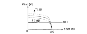
図4に充電許容電力Wim1と、充電率SOC1及び温度T1との関係を表す図を示す。充電率SOC1の増加に応じて、開放端電圧OCV1が上昇することで、充電許容電力Wim1は減少する。また、温度T1の低下に応じて、内部抵抗Ri1が増加することで、充電許容電力Wim1は減少する。 FIG. 4 is a diagram showing the relationship between the charge allowable power Wim1, and the charging rate SOC1 and the temperature T1. In response to the increase of the charging rate SOC1, the open circuit voltage OCV1 is increased, whereby the charge allowable power Wim1 is decreased. Further, the charge allowable power Wim1 decreases due to the increase of the internal resistance Ri1 according to the decrease of the temperature T1.
このように、制御部50は、放電許容電力Wom1と、充電率SOC1及び温度T1との関係を表すマップ(図3)を予め記憶し、そのマップと、充電率SOC1及び温度T1とに基づいて、放電許容電力Wom1を算出することができる。また、制御部50は、充電許容電力Wim1と、充電率SOC1及び温度T1との関係を表すマップ(図4)を予め記憶し、そのマップと、充電率SOC1及び温度T1とに基づいて、充電許容電力Wim1を算出することができる。なお、放電許容電力Wom1及び充電許容電力Wim1の算出時において、内部抵抗Ri1の値は用いなくてもよい。
Thus,
以下、放電許容電力Wom1と、充電率SOC1及び温度T1との関係を表すマップの作成方法について説明する。充電率SOC1及び温度T1をそれぞれ所定の値に設定した上で、所定の放電実施時間Toにわたって一定電流を電池群C1に対して流したときに、下限値Vminに到達する電流値を取得する。その取得した電流値と下限値Vminとの積の値を放電許容電力Wom1として取得する。そして、充電率SOC1及び温度T1のそれぞれの値と、放電許容電力Wom1の値との対応を表すマップを作成する。 Hereinafter, a method of creating a map representing the relationship between discharge allowable power Wom1, charging rate SOC1 and temperature T1 will be described. After setting the charging rate SOC1 and the temperature T1 to predetermined values, when a constant current is supplied to the battery group C1 for a predetermined discharge execution time To, a current value that reaches the lower limit value Vmin is acquired. The value of the product of the acquired current value and lower limit value Vmin is acquired as discharge allowable power Wom1. Then, a map representing the correspondence between the values of the charging rate SOC1 and the temperature T1 and the values of the allowable discharge power Wom1 is created.
また、充電許容電力Wim1と、充電率SOC1及び温度T1との関係を表すマップ作成方法を説明する。所定の充電実施時間Tiにわたって一定電流を電池群C1に対して流したときに、上限値Vmaxに到達する電流値を取得する。その取得した電流値と、開放端電圧OCV1との積の値を充電許容電力Wim1として取得する。そして、充電率SOC1及び温度T1のそれぞれの値と、充電許容電力Wim1の値との対応を表すマップを作成する。 In addition, a map generation method will be described that represents the relationship between the charge allowable power Wim1, the charging rate SOC1, and the temperature T1. When a constant current is supplied to the battery group C1 for a predetermined charging time Ti, a current value that reaches the upper limit value Vmax is acquired. A value of the product of the acquired current value and the open end voltage OCV1 is acquired as the charge allowable power Wim1. Then, a map representing the correspondence between each value of charging rate SOC1 and temperature T1 and the value of charging allowable power Wim1 is created.
ここで、図3に示すように、放電許容電力Wom1は、放電による充電率SOC1の減少に伴い減少し、放電電力Wo1より小さくなることが懸念される。放電許容電力Wom1が放電電力Wo1より小さくなることで、負荷100に供給される電圧が下限電圧Vminより低くなり、負荷100の動作が不安定になるなどの問題が生じる。
Here, as shown in FIG. 3, it is feared that discharge allowable power Wom1 decreases with the decrease of the charging rate SOC1 due to discharge and becomes smaller than discharge power Wo1. When discharge allowable power Wom1 becomes smaller than discharge power Wo1, the voltage supplied to load 100 becomes lower than lower limit voltage Vmin, causing problems such as the operation of
また、図4に示すように、充電許容電力Wim1は、充電による充電率SOC1の増加に伴い減少し、充電電力Wi1より小さくなることが懸念される。充電許容電力Wim1が充電電力Wi1より小さくなることで、電池群C1の端子間電圧CCV1が上限電圧Vmaxより高くなり、負荷100の動作が不安定になるなどの問題が生じる。
Further, as shown in FIG. 4, it is feared that the charge allowable power Wim1 decreases with the increase of the charging rate SOC1 due to charging and becomes smaller than the charge power Wi1. Since the charge allowable power Wim1 is smaller than the charge power Wi1, the inter-terminal voltage CCV1 of the battery group C1 becomes higher than the upper limit voltage Vmax, causing problems such as the operation of the
そこで、本実施形態では、電池群C1,C2の少なくとも一方で、放電許容電力Wom1,Wom2が、その電池群C1,C2から放電されている放電電力Wo1,Wo2を下回る場合に、充電率SOC1,SOC2が所定値(第1所定値)未満であると判定し、電流調整制御を実施する構成とした。また、電池群C1,C2の少なくとも一方において、充電許容電力Wim1,Wim2が、その電池群C1,C2から充電されている充電電力Wi1,Wi2を下回る場合に、充電率SOC1,SOC2が所定値(第2所定値)より大きいと判定し、電流調整制御を実施する構成とした。 Therefore, in the present embodiment, when at least one of battery groups C1 and C2 allows discharge allowable powers Wom1 and Wom2 to be lower than discharge powers Wo1 and Wo2 discharged from battery groups C1 and C2, charging rate SOC1, SOC2 is lower. It is determined that the SOC2 is less than a predetermined value (first predetermined value), and the current adjustment control is performed. When at least one of battery groups C1 and C2 has charge allowable powers Wim1 and Wim2 below charging powers Wi1 and Wi2 charged from battery groups C1 and C2, charging rates SOC1 and SOC2 have predetermined values ( It is determined that the value is larger than the second predetermined value, and the current adjustment control is performed.
図5に、電池群C1,C2の充電率SOC1,SOC2の算出処理を表すフローチャートを示す。当該処理は、所定周期毎に制御部50によって実施される。
FIG. 5 is a flowchart showing the process of calculating the charging rates SOC1 and SOC2 of the battery groups C1 and C2. The said process is implemented by the
ステップS01において、蓄電システム10が充放電中であるか否かを判定する。蓄電システム10が充放電中でない場合(S01:NO)、ステップS02において、電圧センサ32よる出力電圧Vの検出値を、各電池群C1,C2の開放端電圧OCV1,OCV2として取得するのに適した状況であるか否かを判定する。ここで、各電池群C1,C2の開放端電圧として取得するのに適した状況とは、具体的には、電池群C1の開放端電圧OCV1と電池群C2の開放端電圧OCV2との差が略0であり、電池群C1,C2間で電流が流れておらず、かつ、電池群C1,C2の分極が緩和されている状況のことである。
In step S01, it is determined whether or not the
電池群C1,C2の開放端電圧OCV1,OCV2を取得するのに適した状況である場合(S02:YES)、ステップS03において、電圧センサ32よる出力電圧Vの検出値を、各電池群C1,C2の開放端電圧OCV1,OCV2として取得し、ステップS04において、その取得した開放端電圧OCV1,OCV2と、開放端電圧と充電率との対応を表すマップとに基づいて、電池群C1,C2の充電率SOC1,SOC2を算出し、処理を終了する。また、電池群C1,C2の開放端電圧OCV1,OCV2を取得するのに適しない状況である場合(S02:NO)、処理を終了する。
If the condition is suitable for acquiring the open end voltages OCV1 and OCV2 of the battery groups C1 and C2 (S02: YES), in step S03, the detection value of the output voltage V by the
蓄電システム10が充放電中である場合(S01:YES)、ステップS05において、各電池群C1,C2の充電率SOC1,SOC2の前回値を取得する。ステップS06において、各電池群C1,C2の温度T1,T2の検出値を取得する。ステップS07において、電流センサ31による組電池11の充放電電流Iの検出値と、電圧センサ32による出力電圧Vの検出値を取得する。ステップS08において、各電池群C1,C2の充電率SOC1,SOC2と、充電率と開放端電圧との対応を表すマップとに基づいて、各電池群C1,C2の開放端電圧OCV1,OCV2を算出する。
If the
ステップS09において、各電池群C1,C2の充電率SOC1,SOC2と、各電池群C1,C2の温度T1,T2と、充電率及び温度と内部抵抗との対応を表すマップと、に基づいて、各電池群C1,C2の内部抵抗Ri1,Ri2を算出する。さらに、各電池群C1,C2の容量維持率に基づいて、各電池群C1,C2の内部抵抗Ri1,Ri2を算出する。ここで、容量維持率とは、満充電容量の初期値に対する満充電容量の現在値との比率を表す値であり、各電池群C1,C2(電池セルC11〜C18,C21〜C28)の劣化を表す値である。具体的には、各電池群C1,C2の容量維持率に基づいて、充電率及び温度と内部抵抗との対応を表すマップを切り替える。 In step S09, based on the charging rates SOC1 and SOC2 of the battery groups C1 and C2, the temperatures T1 and T2 of the battery groups C1 and C2, and the maps representing the charging rates and the correspondence between the temperature and the internal resistance, The internal resistances Ri1 and Ri2 of the battery groups C1 and C2 are calculated. Furthermore, internal resistances Ri1 and Ri2 of the battery groups C1 and C2 are calculated based on the capacity maintenance rates of the battery groups C1 and C2. Here, the capacity retention rate is a value representing the ratio of the full charge capacity to the current value of the full charge capacity to the initial value, and deterioration of each of the battery groups C1 and C2 (battery cells C11 to C18 and C21 to C28). Is a value representing Specifically, based on the capacity maintenance rates of the battery groups C1 and C2, a map representing the correspondence between the charging rate and the temperature and the internal resistance is switched.
ステップS10において、各電池群C1,C2の開放端電圧OCV1,OCV2、組電池11の充放電電流I、及び、各電池群C1,C2の内部抵抗Ri1,Ri2に基づいて、各電池群C1,C2に流れる充放電電流I1,I2を算出する。ステップS11において、各電池群C1,C2の充電率SOC1,SOC2の前回値に対し、充放電電流I1,I2から算出される充電率の変化量ΔSOC1,ΔSOC2を加算することで、充電率の現在値を算出し、処理を終了する。
In step S10, based on open end voltages OCV1 and OCV2 of respective battery groups C1 and C2, charge / discharge current I of assembled
ここで、ステップS10における各電池群C1,C2に流れる充放電電流I1,I2を算出する方法について詳述する。充放電電流I1,I2は、
I=I1+I2
という関係を有する。さらに、電池群C1と可変抵抗回路R1との直列接続体の端子間電圧V1と、電池群C2と可変抵抗回路R2との直列接続体の端子間電圧V2とは、
V1=OCV1−I1・(Ri1+R1)
V2=OCV2−I2・(Ri2+R2)
という関係を有する。ここで、V1=V2=Vであるため、R1=R2=0とすると、充放電電流I1,I2は、
I1=(OCV1−OCV2+I・Ri1)/(Ri1+Ri2)
I2=I−I1
として算出することができる。
Here, the method of calculating the charge / discharge currents I1 and I2 flowing to the respective battery groups C1 and C2 in step S10 will be described in detail. The charge and discharge currents I1 and I2 are
I = I1 + I2
It has a relationship of Furthermore, the voltage V1 across the terminals of the series connection of the battery group C1 and the variable resistance circuit R1 and the voltage V2 across the terminals of the series connection of the battery group C2 and the variable resistance circuit R2 are
V1 = OCV1−I1 · (Ri1 + R1)
V2 = OCV2−I2 · (Ri2 + R2)
It has a relationship of Here, since V1 = V2 = V, assuming that R1 = R2 = 0, the charge / discharge currents I1 and I2 are
I1 = (OCV1−OCV2 + I · Ri1) / (Ri1 + Ri2)
I2 = I-I1
It can be calculated as
また、ステップS11において、充電率の変化量ΔSOC1,ΔSOC2は、
ΔSOC1=∫I1・dt/Af1
ΔSOC2=∫I2・dt/Af2
として算出することができる。ここで、Af1,Af2は、各電池群C1,C2の満充電容量である。
Also, in step S11, the change rates ΔSOC1, ΔSOC2 of the charging rate are
ΔSOC1 = ∫I1 · dt / Af1
ΔSOC2 = ∫I2 · dt / Af2
It can be calculated as Here, Af1 and Af2 are full charge capacities of the respective battery groups C1 and C2.
図6に、蓄電システム10の出力調整処理を表すフローチャートを示す。当該処理は、所定周期毎に制御部50によって実施される。ここで、出力調整処理が実施される周期である所定周期は、前述した放電許容電力Wom1,Wom2の取得に用いる放電実施時間Toより短い周期にされている。これにより、放電電力Wo1,Wo2が放電許容電力Wom1,Wom2を一時的に上回ることを抑制できる。同様に、出力調整処理が実施される周期である所定周期は、前述した充電許容電力Wim1,Wim2の取得に用いる充電実施時間Tiより短い周期にされている。これにより、充電電力Wi1,Wi2が充電許容電力Wim1,Wim2を一時的に上回ることを抑制できる。
FIG. 6 shows a flowchart representing the output adjustment process of
ステップS21において、各電池群C1,C2の充電率SOC1,SOC2を取得する。ステップS22において、各電池群C1,C2の温度T1,T2を取得する。ステップS23において、充放電電流Iの正負に基づいて、組電池11が放電中であるか否かを判定する。
In step S21, charging rates SOC1 and SOC2 of the battery groups C1 and C2 are acquired. In step S22, temperatures T1 and T2 of the battery groups C1 and C2 are acquired. In step S23, it is determined based on whether the charge / discharge current I is positive or negative, whether or not the assembled
組電池11が放電中である場合(S23:YES)、ステップS24において、各電池群C1,C2の充電率SOC1,SOC2及び各電池群C1,C2の温度T1,T2と、充電率SOC1,SOC2及び温度T1,T2と各電池群C1,C2の放電許容電力Wom1,Wom2との関係を表すマップと、に基づいて、各電池群C1,C2の放電許容電力Wom1,Wom2を算出する。
If the
ステップS25において、各電池群C1,C2に流れる充放電電流I1,I2を取得する。ステップS26において、各電池群C1,C2の端子間電圧CCV1,CCV2を算出する。ステップS27において、充放電電流I1,I2と、端子間電圧CCV1,CCV2との積を、各電池群C1,C2から現在放電されている放電電力Wo1,Wo2として算出する。 In step S25, charge / discharge currents I1 and I2 flowing through the battery groups C1 and C2 are acquired. In step S26, terminal voltages CCV1 and CCV2 of the battery groups C1 and C2 are calculated. In step S27, products of charge / discharge currents I1 and I2 and voltages across terminals CCV1 and CCV2 are calculated as discharge powers Wo1 and Wo2 currently discharged from the respective battery groups C1 and C2.
ステップS28において、放電電力Wo1,Wo2と、放電許容電力Wom1,Wom2との比較を行う。放電許容電力Wom1,Wom2が、それぞれ放電電力Wo1,Wo2以上の場合(S28:NO)、ステップS29において、可変抵抗回路R1,R2の抵抗値をともに0に設定し、処理を終了する。 In step S28, discharge powers Wo1 and Wo2 are compared with discharge allowable powers Wom1 and Wom2. If discharge allowable powers Wom1 and Wom2 are respectively equal to or higher than discharge powers Wo1 and Wo2 (S28: NO), the resistances of variable resistance circuits R1 and R2 are both set to 0 in step S29, and the process is ended.
放電許容電力Wom1,Wom2の少なくとも一方が、放電電力Wo1,Wo2未満の場合(S28:YES)、ステップS30において、各電池群C1,C2に流すのに適した電流の目標値I1*,I2*を設定する。具体的には、目標値I1*と目標値I2*との比が、充電率SOC1と充電率SOC2との比となるように、目標値I1*,I2*を設定する。具体的には、目標値I1*,I2*を
I1*=I・SOC1/(SOC1+SOC2)
I2*=I・SOC2/(SOC1+SOC2)
として設定する。
If at least one of discharge allowable powers Wom1 and Wom2 is smaller than discharge powers Wo1 and Wo2 (S28: YES), target values I1 * and I2 * of currents suitable for flowing to respective battery groups C1 and C2 in step S30. Set Specifically, the target values I1 * and I2 * are set such that the ratio between the target value I1 * and the target value I2 * is the ratio between the charging rate SOC1 and the charging rate SOC2. Specifically, the target values I1 * and I2 * are expressed as I1 * = I · SOC1 / (SOC1 + SOC2)
I2 * = I · SOC2 / (SOC1 + SOC2)
Set as.
ステップS31において、可変抵抗回路R1,R2の値を設定する。電池群C1,C2に流れる電流I1,I2は、OCV1=OCV2とみなすと、
I1:I2=Ri2+R2:Ri1+R1
という関係を有する。また、目標値I1*,I2*は、
I1*:I2*=SOC1:SOC2
という関係を有する。
In step S31, values of variable resistance circuits R1 and R2 are set. If the currents I1 and I2 flowing to the battery groups C1 and C2 are regarded as OCV1 = OCV2, then
I1: I2 = Ri2 + R2: Ri1 + R1
It has a relationship of Also, target values I1 * and I2 * are
I1 *: I2 * = SOC1: SOC2
It has a relationship of
このため、
Ri1+R1:Ri2+R2=SOC2:SOC1
という関係が成立するように可変抵抗回路R1,R2の抵抗値R1,R2を設定するとよい。具体的には、R1及びR2のうち一方を0としつつ、他方が正の値となるように、
R1=0,R2=Ri1・SOC1/SOC2−Ri2(>0)
または、
R1=Ri2・SOC2/SOC1−Ri1(>0),R2=0
と設定する。
For this reason,
Ri1 + R1: Ri2 + R2 = SOC2: SOC1
The resistance values R1 and R2 of the variable resistance circuits R1 and R2 may be set so as to establish the following relationship. Specifically, while making one of
R1 = 0, R2 = Ri1 · SOC1 / SOC2-Ri2 (> 0)
Or
R1 = Ri2 · SOC2 / SOC1−Ri1 (> 0), R2 = 0
Set as
ステップS31の後、ステップS32において、冷却装置21,22の制御を実施する。具体的には、電池群C1,C2のうち充電率の小さい(充放電電流の目標値I1*,I2*の小さい)方の電池群の温度が、充電率の大きい方の電池群に比べて低くなるように冷却装置21,22を制御する。ステップS32の後、処理を終了する。
After step S31, control of the
ステップS23において、組電池11が放電中でない判定された場合(S23:NO)、ステップS33において、組電池11が充電中であるか否かを判定する。組電池11が充電中でない場合(S33:NO)、処理を終了する。組電池11が充電中である場合(S33:YES)、ステップS34において、各電池群C1,C2の充電率SOC1,SOC2及び各電池群C1,C2の温度T1,T2と、充電率SOC1,SOC2及び温度T1,T2と各電池群C1,C2の充電許容電力Wim1,Wim2との関係を表すマップと、に基づいて、各電池群C1,C2の充電許容電力Wim1,Wim2を算出する。
If it is determined in step S23 that the
ステップS35において、各電池群C1,C2に流れる充放電電流I1,I2を取得する。ステップS36において、各電池群C1,C2の端子間電圧CCV1,CCV2を算出する。ステップS37において、充放電電流I1,I2と、端子間電圧CCV1,CCV2との積を、各電池群C1,C2から現在放電されている充電電力Wi1,Wi2として算出する。 In step S35, charge / discharge currents I1 and I2 flowing through the battery groups C1 and C2 are acquired. In step S36, the inter-terminal voltages CCV1 and CCV2 of the battery groups C1 and C2 are calculated. In step S37, products of charge / discharge currents I1 and I2 and inter-terminal voltages CCV1 and CCV2 are calculated as charge powers Wi1 and Wi2 currently discharged from the respective battery groups C1 and C2.
ステップS38において、充電電力Wi1,Wi2と、充電許容電力Wim1,Wim2との比較を行う。充電許容電力Wim1,Wim2が、それぞれ充電電力Wi1,Wi2以上の場合(S38:NO)、ステップS39において、可変抵抗回路R1,R2の値をともに0に設定し、処理を終了する。 In step S38, the charging powers Wi1 and Wi2 are compared with the charging allowable powers Wim1 and Wim2. If the charge allowable powers Wim1 and Wim2 are respectively equal to or higher than the charge powers Wi1 and Wi2 (S38: NO), the values of the variable resistance circuits R1 and R2 are both set to 0 in step S39, and the process is ended.
充電許容電力Wim1,Wim2の少なくとも一方が、充電電力Wi1,Wi2未満の場合(S38:YES)、ステップS40において、各電池群C1,C2に流すのに適した電流の目標値I1*,I2*を設定する。具体的には、目標値I1*と目標値I2*との比が、「100−SOC1」と「100−SOC2」との比となるように、目標値I1*,I2*を設定する。具体的には、目標値I1*,I2*を
I1*=I・(100−SOC1)/(200−SOC1−SOC2)
I2*=I・(100−SOC2)/(200−SOC1−SOC2)
として設定する。なお、上記式において、SOC1,SOC2は百分率として表している。
If at least one of charge allowable powers Wim1 and Wim2 is less than charge powers Wi1 and Wi2 (S38: YES), target values I1 * and I2 * of currents suitable for flowing to respective battery groups C1 and C2 in step S40. Set Specifically, the target values I1 * and I2 * are set such that the ratio of the target value I1 * to the target value I2 * is the ratio of “100−SOC1” to “100−SOC2”. Specifically, the target values I1 * and I2 * are expressed as I1 * = I · (100−SOC1) / (200−SOC1−SOC2)
I2 * = I. (100-SOC2) / (200-SOC1-SOC2)
Set as. In the above equation, SOC1 and SOC2 are expressed as percentages.
ステップS41において、可変抵抗回路R1,R2の値を設定する。電池群C1,C2に流れる電流I1,I2は、OCV1=OCV2とみなすと、
I1:I2=Ri2+R2:Ri1+R1
という関係を有する。また、目標値I1*,I2*は、
I1*:I2*=100−SOC1:100−SOC2
という関係を有する。このため、
Ri1+R1:Ri2+R2=100−SOC2:100−SOC1
という関係が成立するように可変抵抗回路R1,R2の抵抗値R1,R2を設定するとよい。具体的には、R1及びR2のうち一方を0としつつ、他方が正の値となるように、
R1=0,R2=Ri1・(100−SOC1)/(100−SOC2)−Ri2(>0)
または、
R1=Ri2・(100−SOC2)/(100−SOC1)−Ri1(>0),R2=0
と設定する。
In step S41, values of variable resistance circuits R1 and R2 are set. If the currents I1 and I2 flowing to the battery groups C1 and C2 are regarded as OCV1 = OCV2, then
I1: I2 = Ri2 + R2: Ri1 + R1
It has a relationship of Also, target values I1 * and I2 * are
I1 *: I2 * = 100-SOC1: 100-SOC2
It has a relationship of For this reason,
Ri1 + R1: Ri2 + R2 = 100-SOC2: 100-SOC1
The resistance values R1 and R2 of the variable resistance circuits R1 and R2 may be set so as to establish the following relationship. Specifically, while making one of
R1 = 0, R2 = Ri1 (100-SOC1) / (100-SOC2) -Ri2 (> 0)
Or
R1 = Ri2 · (100−SOC2) / (100−SOC1) −Ri1 (> 0), R2 = 0
Set as
ステップS41の後、ステップS42において、冷却装置21,22の制御を実施する。具体的には、電池群C1,C2のうち充電率の大きい(充放電電流の目標値I1*,I2*の小さい)方の電池群の温度が、充電率の小さい方の電池群に比べて低くなるように冷却装置21,22を制御する。ステップS42の後、処理を終了する。
After step S41, control of the
以下、本実施形態の効果について述べる。 The effects of this embodiment will be described below.
上記構成によれば、蓄電システム10の放電時において、複数の電池群C1,C2のいずれかの充電率SOC1,SOC2が所定値未満である場合、電池群C1,C2に対し、充電率が大きいほど大きな放電電流が流れるように、可変抵抗回路R1,R2の抵抗値が設定される。これにより、放電を行いながら、電池群C1,C2の充電率SOC1,SOC2を互いに近づけることが可能になる。また、全ての電池群C1,C2の充電率SOC1,SOC2が所定値以上である場合、全ての可変抵抗回路R1,R2の抵抗値が最低値(略0)に設定されるため、可変抵抗回路R1,R2における電力消費を低減できる。
According to the above configuration, when the charge rate SOC1, SOC2 of any of the plurality of battery groups C1, C2 is less than the predetermined value when the
同様に、蓄電システム10の充電時において、複数の電池群C1,C2のいずれかの充電率SOC1,SOC2が所定値より大きい場合、電池群C1,C2に対し、充電率SOC1,SOC2が大きいほど小さな充電電流が流れるように、可変抵抗回路R1,R2の抵抗値が設定される。これにより、充電を行いながら、電池群C1,C2の充電率SOC1,SOC2を互いに近づけることが可能になる。また、全ての電池群C1,C2の充電率が所定値以下である場合、全ての可変抵抗回路R1,R2の抵抗値が最低値(略0)に設定されるため、可変抵抗回路R1,R2における電力消費を低減できる。
Similarly, when charging rate SOC1, SOC2 of one of the plurality of battery groups C1, C2 is larger than the predetermined value during charging of
つまり、上記構成によれば、充放電を行いながら、電池群C1,C2の充電率SOC1,SOC2を互いに近づけることが可能であるとともに、さらに、可変抵抗回路R1,R2における電力消費を低減可能である。 That is, according to the above configuration, it is possible to make the charging rates SOC1 and SOC2 of the battery groups C1 and C2 close to each other while performing charge and discharge, and further reduce the power consumption in the variable resistance circuits R1 and R2. is there.
具体的には、特許文献1(特許5342860号公報)に記載の構成と比べて、放電時において、組電池11の温度が10℃程度の領域で、電力効率が0.1%向上し、組電池11の温度が0℃程度の領域で、電力効率が1.3%向上するという結果を得た。組電池11の温度が0℃程度の低温領域では、電池群C1,C2の内部抵抗Ri1,Ri2の値が大きくなり、その大きさにあわせて可変抵抗回路R1,R2の抵抗値を大きくする必要がある。このため、低温領域において、本実施形態の構成は、可変抵抗回路R1,R2による電力調整を常時実施する構成と比べて、顕著に電力効率が向上する。
Specifically, compared to the configuration described in Patent Document 1 (Japanese Patent No. 5342860), the power efficiency is improved by 0.1% in the region where the temperature of the assembled
本実施形態の構成では、充電率及び電池群C1,C2の内部抵抗Ri1,Ri2に基づいて、可変抵抗回路R1,R2の抵抗値を設定する。これにより、放電時において、充電率SOC1,SOC2を同時に所定値(例えば、0%)にすることが可能になる。また、充電時において、充電率SOC1,SOC2を同時に所定値(例えば、100%)にすることが可能になる。 In the configuration of the present embodiment, the resistance values of the variable resistance circuits R1 and R2 are set based on the charging rate and the internal resistances Ri1 and Ri2 of the battery groups C1 and C2. This makes it possible to simultaneously set the charging rates SOC1 and SOC2 to predetermined values (for example, 0%) at the time of discharging. Further, at the time of charging, it is possible to simultaneously set the charging rates SOC1 and SOC2 to predetermined values (for example, 100%).
電池群C1,C2が劣化する場合、容量維持率が低下するとともに、内部抵抗Ri1,Ri2が増加する。ここで、容量維持率の低下と内部抵抗Ri1,Ri2の増加とは相関を有する。そこで、本実施形態では、容量維持率に基づいて、内部抵抗Ri1,Ri2を算出する構成とした。 When the battery groups C1 and C2 deteriorate, the capacity retention rate decreases and the internal resistances Ri1 and Ri2 increase. Here, there is a correlation between the decrease in capacity retention rate and the increase in internal resistances Ri1 and Ri2. Therefore, in the present embodiment, the internal resistances Ri1 and Ri2 are calculated based on the capacity retention ratio.
放電時において、電池群C1,C2の少なくとも一方で、放電許容電力Wom1,Wom2が、その電池群C1,C2から放電されている放電電力Wo1,Wo2を下回る場合に、充電率SOC1,SOC2が所定値未満であると判定し、電流調整制御を実施する構成とした。本構成により、放電電力Wo1,Wo2が、放電許容電力Wom1,Wom2を越えることを抑制することが可能になる。これにより、蓄電システム10の出力電圧Vが、下限電圧Vminを越えて低下することを抑制し、負荷100の動作が不安定になることを抑制できる。
At the time of discharge, if at least one of battery groups C1 and C2 allows discharge allowable powers Wom1 and Wom2 to be lower than discharge powers Wo1 and Wo2 discharged from battery groups C1 and C2, charge rates SOC1 and SOC2 are predetermined. It is determined that the current value is less than the value, and the current adjustment control is performed. According to this configuration, discharge powers Wo1 and Wo2 can be prevented from exceeding discharge allowable powers Wom1 and Wom2. As a result, the output voltage V of the
また、充電時において、電池群C1,C2の少なくとも一方において、充電許容電力Wim1,Wim2が、その電池群C1,C2から放電されている充電電力Wi1,Wi2を下回る場合に、充電率SOC1,SOC2が所定値より大きいと判定し、電流調整制御を実施する構成とした。本構成により、充電電力Wi1,Wi2が、充電許容電力Wim1,Wim2を越えることを抑制することが可能になる。これにより、蓄電システム10の出力電圧Vが、上限電圧Vmaxを越えて上昇することを抑制し、負荷100の動作が不安定になることを抑制できる。
Further, at the time of charging, when at least one of battery groups C1 and C2 has charge allowable powers Wim1 and Wim2 smaller than charge powers Wi1 and Wi2 discharged from battery groups C1 and C2, charging rates SOC1 and SOC2 are Is determined to be larger than a predetermined value, and current adjustment control is performed. With this configuration, it is possible to suppress that the charging powers Wi1 and Wi2 exceed the charging allowable powers Wim1 and Wim2. Thus, the output voltage V of the
二次電池は、温度が低いほど、内部抵抗が増加するという特性を有する。そこで、放電時において、充電率の小さい電池群C1,C2ほど、その電池群C1,C2の温度が低くなるように、冷却装置21,22による冷却を実施する。これにより、温度上昇に伴う電池群C1,C2の劣化の抑制が可能になるとともに、可変抵抗回路R1,R2における電力消費を低減することが可能になる。
The secondary battery has a characteristic that the internal resistance increases as the temperature is lower. Therefore, cooling is performed by the
同様に、充電時において、充電率の小さい電池群C1,C2ほど、その電池群C1,C2の温度が低くなるように、冷却装置21,22による冷却を実施する。これにより、温度上昇に伴う電池群C1,C2の劣化の抑制が可能になるとともに、可変抵抗回路R1,R2における電力消費を低減することが可能になる。
Similarly, at the time of charging, cooling is performed by the
(第2実施形態)
図7に第2実施形態における電気的構成を示す。図1に示す第1実施形態における電気的構成と同一の構成については同一の符号を付し、説明を省略する。
Second Embodiment
FIG. 7 shows an electrical configuration in the second embodiment. The same components as those in the electrical configuration of the first embodiment shown in FIG.
第2実施形態の構成では、組電池11に流れる充放電電流Iを検出する電流センサ31に代えて、電池群C1,C2に流れる充放電電流I1,I2をそれぞれ検出する電流センサ31a,31bを設けている。
In the configuration of the second embodiment, instead of the
図8に、電池群C1,C2の充電率の算出処理を表すフローチャートを示す。当該処理は、所定周期毎に制御部50によって実施される。図5に示す第1実施形態と同一の処理については同一の符号を付し、説明を省略する。
FIG. 8 is a flowchart showing the process of calculating the charging rate of the battery groups C1 and C2. The said process is implemented by the
蓄電システム10が充放電中である場合(S01:YES)、ステップS05において、各電池群C1,C2の充電率SOC1,SOC2の前回値を取得する。ステップS12において、電流センサ31a,31bから充放電電流I1,I2の検出値を取得する。その後、ステップS11において、各電池群C1,C2の充電率SOC1,SOC2の前回値に対し、充放電電流I1,I2から算出される充電率の変化量ΔSOC1,ΔSOC2を加算することで、充電率の現在値を算出し、処理を終了する。
If the
第2実施形態の構成によれば、第1実施形態の構成と比較して、簡易な構成で、精度よく各電池群C1,C2の充電率SOC1,SOC2を算出することができる。なお、第1実施形態の構成は、第2実施形態の構成と比較して、電流センサを用いる数を低減できるため、蓄電システム10の体格が増加することを抑制し、また、製造コストを低減させることが可能となる。
According to the configuration of the second embodiment, compared with the configuration of the first embodiment, the charging rates SOC1 and SOC2 of the battery groups C1 and C2 can be accurately calculated with a simple configuration. The configuration of the first embodiment can reduce the number of current sensors used as compared with the configuration of the second embodiment, and therefore can suppress an increase in the physical size of the
(第3実施形態)
第1実施形態の図6に示すフローチャートのステップS31において、電池群C1,C2の開放端電圧OCV1,OCV2が等しいとみなして、可変抵抗回路R1,R2の抵抗値R1,R2を設定する構成とした。これを変更してもよい。
Third Embodiment
In step S31 of the flowchart shown in FIG. 6 of the first embodiment, the open end voltages OCV1 and OCV2 of the battery groups C1 and C2 are regarded as equal, and the resistance values R1 and R2 of the variable resistance circuits R1 and R2 are set. did. You may change this.
例えば、放電時において、SOC1>SOC2であり、可変抵抗回路R1の抵抗値R1を0に設定する状況下では、
OCV1−I1・Ri1=OCV2−I2(Ri2+R2)…(1)
という関係を有する。ここで、
I=I1+I2
であるため、式(1)は、
OCV1−I1・Ri1=OCV2−(I−I1)(Ri2+R2)
と変形できる。さらに、
−(Ri1+Ri2+R2)I1=OCV2−I(Ri2+R2)−OCV1
と変形できるため、充放電電流I1は、
I1=(OCV1−OCV2+I(Ri2+R2))/(Ri1+Ri2+R2)
と表すことができる。さらに、充放電電流I2は、
I2=I−I1
=(−OCV1+OCV2+I・Ri1)/(Ri1+Ri2+R2)
と表すことができる。
For example, under the condition that SOC1> SOC2 at the time of discharge and the resistance value R1 of the variable resistance circuit R1 is set to 0,
OCV1-I1.Ri1 = OCV2-I2 (Ri2 + R2) (1)
It has a relationship of here,
I = I1 + I2
Because equation (1) is
OCV1-I1.Ri1 = OCV2- (I-I1) (Ri2 + R2)
Can be deformed. further,
-(Ri1 + Ri2 + R2) I1 = OCV2-I (Ri2 + R2) -OCV1
The charge / discharge current I1 is
I1 = (OCV1-OCV2 + I (Ri2 + R2)) / (Ri1 + Ri2 + R2)
It can be expressed as. Furthermore, the charge / discharge current I2 is
I2 = I-I1
= (-OCV1 + OCV2 + I.Ri1) / (Ri1 + Ri2 + R2)
It can be expressed as.
また、充放電電流I1,I2の目標値I1*,I2*は、
I1*:I2*=SOC1:SOC2
という関係を有する。このため、充放電電流I1,I2を目標値I1*,I2*とするには、
SOC1・I2=SOC2・I1…(2)
を満たすように可変抵抗回路R2の抵抗値R2を設定するとよい。即ち、式(2)に上記I1,I2を代入すると、
SOC1・(−OCV1+OCV2+I・Ri1)/(Ri1+Ri2+R2)=SOC2・(OCV1−OCV2+I(Ri2+R2))/(Ri1+Ri2+R2)
となり、さらに変形して、
SOC1・(−OCV1+OCV2+I・Ri1)=SOC2・(OCV1−OCV2+I(Ri2+R2))
となり、さらに変形して、
(OCV1−OCV2+I(Ri2+R2))=(SOC1/SOC2)・(−OCV1+OCV2+I・Ri1)
となり、さらに変形して、
(Ri2+R2)=1/I((SOC1/SOC2)・(−OCV1+OCV2+I・Ri1)−(OCV1−OCV2))
となる。
Further, target values I1 * and I2 * of charge and discharge currents I1 and I2 are
I1 *: I2 * = SOC1: SOC2
It has a relationship of Therefore, in order to set the charge and discharge currents I1 and I2 to the target values I1 * and I2 *,
SOC1 · I2 = SOC2 · I1 (2)
The resistance value R2 of the variable resistor circuit R2 may be set to satisfy the following. That is, when the above I1 and I2 are substituted into the equation (2),
SOC1 · (−OCV1 + OCV2 + I · Ri1) / (Ri1 + Ri2 + R2) = SOC2 · (OCV1−OCV2 + I (Ri2 + R2)) / (Ri1 + Ri2 + R2)
And further deform,
SOC1 · (−OCV1 + OCV2 + I · Ri1) = SOC2 · (OCV1−OCV2 + I (Ri2 + R2))
And further deform,
(OCV1-OCV2 + I (Ri2 + R2)) = (SOC1 / SOC2). (-OCV1 + OCV2 + I.Ri1)
And further deform,
(Ri2 + R2) = 1 / I ((SOC1 / SOC2). (-OCV1 + OCV2 + I.Ri1)-(OCV1-OCV2))
It becomes.
よって、抵抗値R2を、
R2=1/I((SOC1/SOC2)・(−OCV1+OCV2+I・Ri1)−(OCV1−OCV2)−Ri2
と設定することで、電池群C1,C2の開放端電圧OCV1,OCV2が互いに大きく異なる場合であっても、電池群C1,C2の充電率SOC1,SOC2をともに0%になるまで放電を行うことが可能になる。
Therefore, the resistance value R2 is
R2 = 1 / I ((SOC1 / SOC2). (-OCV1 + OCV2 + I.Ri1)-(OCV1-OCV2) -Ri2
Even if the open end voltages OCV1 and OCV2 of the battery groups C1 and C2 are largely different from each other, discharging is performed until both the charging rates SOC1 and SOC2 of the battery groups C1 and C2 become 0%. Becomes possible.
(他の実施形態)
・上記実施形態では、組電池11が備える電池群の数を「2」としているが、これを変更し、電池群の数を2以上の任意の自然数としてもよい。また、電池群C1,C2がそれぞれ備える電池セルの数を「8」としているが、電池群がそれぞれ備える電池セルの数を任意の自然数に変更してもよい。また、可変抵抗回路R1,R2がそれぞれ備える抵抗素子及びスイッチの数を「5」としているが、可変抵抗回路R1,R2がそれぞれ備える抵抗素子及びスイッチの数を任意の自然数に変更してもよい。
(Other embodiments)
-Although the number of the battery groups with which the assembled
・「蓄電素子」は、リチウムイオン二次電池に代えて、鉛二次電池やニッケル水素二次電池のような他の二次電池であってもよい。また、「蓄電素子」は、電池セルの直列接続体に代えて、単一の電池セルであってもよい。また、「蓄電素子」は電気二重層キャパシタであってもよい。 -"Electric storage element" may be replaced with a lithium ion secondary battery, and may be other secondary batteries such as a lead secondary battery or a nickel hydrogen secondary battery. Also, the "storage element" may be a single battery cell instead of the series connection of battery cells. Further, the "storage element" may be an electric double layer capacitor.
・冷却装置21,22を省略する構成としてもよい。また、冷却装置21として、冷却ファン(空冷装置)に代えて、水などの液体を冷媒として用いる水冷装置であってもよい。
The
・「放電制御」と「充電制御」とのいずれか一方のみを実施する構成としてもよい。 The configuration may be such that only one of the “discharge control” and the “charge control” is performed.
・負荷100の動作下限電圧(下限値Vmin)に基づいて、放電許容電力Wom1,Wom2を設定する構成としたが、これを変更してもよい。例えば、各電池群C1,C2に流れる電流I1,I2の最大値に基づいて、放電許容電力Wom1,Wom2を設定する構成とするとよい。同様に、負荷100の動作上限電圧(上限値Vmax)に基づいて、充電許容電力Wim1,Wim2を設定する構成としたが、これを変更してもよい。例えば、各電池群C1,C2に流れる電流I1,I2の最大値に基づいて、充電許容電力Wim1,Wim2を設定する構成とするとよい。
-Although set as the structure which sets discharge allowable electric power Wom1 and Wom2 based on the operation lower limit voltage (lower limit value Vmin) of the
・上記実施形態では、電池群C1,C2の少なくとも一方で、放電許容電力Wom1,Wom2が、その電池群C1,C2から放電されている放電電力Wo1,Wo2を下回る場合に、充電率SOC1,SOC2が所定値未満であると判定し、電流調整制御を実施する構成とした。これを変更し、充電率SOC1,SOC2と所定値とを比較し、充電率SOC1,SOC2の少なくとも一方が、所定値未満である場合に、電流調整制御を実施する構成であってもよい。また、開放端電圧OCV1,OCV2と所定値とを比較し、開放端電圧OCV1,OCV2の少なくとも一方が、所定値未満である場合に、電流調整制御を実施する構成であってもよい。 In the above embodiment, if at least one of battery groups C1 and C2 allows discharge allowable powers Wom1 and Wom2 to be lower than discharge powers Wo1 and Wo2 discharged from battery groups C1 and C2, charging rates SOC1 and SOC2 are obtained. Is determined to be less than a predetermined value, and current adjustment control is performed. This may be changed, the charging rates SOC1 and SOC2 may be compared with a predetermined value, and the current adjustment control may be performed when at least one of the charging rates SOC1 and SOC2 is less than the predetermined value. Alternatively, current adjustment control may be performed by comparing open end voltages OCV1 and OCV2 with a predetermined value and at least one of open end voltages OCV1 and OCV2 is lower than the predetermined value.
また、上記実施形態では、電池群C1,C2の少なくとも一方で、充電許容電力Wim1,Wim2が、その電池群C1,C2に充電されている充電電力Wi1,Wi2を下回る場合に、充電率SOC1,SOC2が所定値より大きいと判定し、電流調整制御を実施する構成とした。これを変更し、充電率SOC1,SOC2と所定値とを比較し、充電率SOC1,SOC2の少なくとも一方が、所定値より大きい場合に、電流調整制御を実施する構成であってもよい。また、開放端電圧OCV1,OCV2と所定値とを比較し、開放端電圧OCV1,OCV2の少なくとも一方が、所定値より大きい場合に、電流調整制御を実施する構成であってもよい。 Further, in the above embodiment, when at least one of battery groups C1 and C2 has charge allowable powers Wim1 and Wim2 lower than charge powers Wi1 and Wi2 charged in battery groups C1 and C2, charging rate SOC1, SOC2 is lower It is determined that the SOC2 is larger than a predetermined value, and the current adjustment control is performed. This may be changed to compare the charging rates SOC1 and SOC2 with a predetermined value, and the current adjustment control may be performed when at least one of the charging rates SOC1 and SOC2 is larger than the predetermined value. Alternatively, the open end voltages OCV1 and OCV2 may be compared with a predetermined value, and current adjustment control may be performed when at least one of the open end voltages OCV1 and OCV2 is larger than the predetermined value.
・上記実施形態では、電池群C1と可変抵抗回路R1との直列接続体、及び、電池群C2と可変抵抗回路R2との直列接続体の電圧(出力電圧)を電圧センサ32により検出し、その検出値に基づいて、電池群C1,C2それぞれの充電率SOC1,SOC2を算出する構成とした。これを変更し、各電池群C1,C2を構成する電池セルC11〜C15,C21〜C25の端子間電圧をそれぞれ検出する電圧センサを設ける構成としてもよい。さらに、各電圧センサの検出値に基づいて、各電池セルC11〜C15,C21〜C25それぞれの充電率を算出する構成とするとよい。このような構成とすることで、各電池群C1,C2を構成する電池セルC11〜C15,C21〜C25のそれぞれにおける過放電及び過充電を抑制することが可能になる。
In the above embodiment, the
・上記実施形態では、各電池群C1,C2の内部抵抗Ri1,Ri2について、充電時及び放電時において同一のマップを用いて算出する構成とした(図5:ステップS09)。これを変更し、充電時と放電時とで、異なるマップを用いて内部抵抗Ri1,Ri2を算出する構成としてもよい。充電時と放電時とで異なるマップを用いて内部抵抗Ri1,Ri2を算出することで、充電時においては、各電池群C1,C2のSOCをともに精度よく100%に近づけることが可能になり、放電時においては、各電池群C1,C2のSOCをともに精度よく0%に近づけることが可能になる。これにより、組電池11の使用可能な充電容量を増加させることが可能になる。
In the above embodiment, the internal resistances Ri1 and Ri2 of the battery groups C1 and C2 are calculated using the same map during charging and discharging (FIG. 5: step S09). This may be changed, and the internal resistances Ri1 and Ri2 may be calculated using different maps at the time of charge and at the time of discharge. By calculating the internal resistances Ri1 and Ri2 using different maps during charging and discharging, it is possible to bring the SOCs of the respective battery groups C1 and C2 close to 100% with high accuracy during charging, At the time of discharge, it is possible to bring the SOCs of the respective battery groups C1 and C2 close to 0% with high accuracy. This makes it possible to increase the usable charge capacity of the
・放電許容電力Wom1及び充電許容電力Wim1について、図2に示すものから変更してもよい。例えば、電池群C1において放電を所定時間にわたって実施する場合、放電に伴って電池群C1の充電率SOC1が低下する。充電率SOC1の低下に伴って、開放端電圧OCV1が低下する。この開放端電圧OCV1の低下を考慮して放電許容電力Wom1を算出する構成としてもよい。同様に、電池群C1において充電を所定時間にわたって実施する場合、充電に伴って電池群C1の充電率SOC1が増加する。充電率SOC1の増加に伴って、開放端電圧OCV1が増加する。この開放端電圧OCV1の増加を考慮して充電許容電力Wim1を算出する構成としてもよい。 The discharge allowable power Wom1 and the charge allowable power Wim1 may be changed from those shown in FIG. For example, when the battery group C1 is discharged for a predetermined time, the charging rate SOC1 of the battery group C1 decreases with the discharge. As the charging rate SOC1 decreases, the open end voltage OCV1 decreases. The configuration may be such that discharge allowable power Wom1 is calculated in consideration of the decrease in open end voltage OCV1. Similarly, when charging is performed in the battery group C1 for a predetermined time, the charging rate SOC1 of the battery group C1 increases with charging. As the charging rate SOC1 increases, the open end voltage OCV1 increases. The charge allowable power Wim1 may be calculated in consideration of the increase of the open end voltage OCV1.
10…蓄電システム、50…制御部、C1,C2…電池群、R1,R2…可変抵抗回路。 10: storage system, 50: control unit, C1, C2: battery group, R1, R2: variable resistance circuit.
Claims (9)
前記蓄電素子にそれぞれ直列接続され、抵抗値が可変である可変抵抗回路(R1,R2)と、
前記蓄電システムの放電時において、全ての前記蓄電素子の充電率が第1所定値以上である場合、全ての前記可変抵抗回路の抵抗値を最小に設定するとともに、前記複数の蓄電素子のいずれかの充電率が前記第1所定値未満である場合、前記蓄電素子の充電率が小さいほど、その蓄電素子に対し小さな放電電流が流れるように、前記可変抵抗回路の抵抗値をそれぞれ設定する放電制御と、
前記蓄電システムの充電時において、全ての前記蓄電素子の充電率が第2所定値以下である場合、全ての前記可変抵抗回路の抵抗値を最小に設定するとともに、前記複数の蓄電素子のいずれかの充電率が前記第2所定値より大きい場合、前記蓄電素子の充電率が大きいほど、その蓄電素子に対し小さな充電電流が流れるように、前記可変抵抗回路の抵抗値をそれぞれ設定する充電制御と、
のうち少なくとも一方の制御を実施する制御部(50)と、を備えることを特徴とする蓄電システム。 A storage system (10) comprising a plurality of storage elements (C1, C2) connected in parallel, comprising:
Variable resistance circuits (R1 and R2) connected in series to the storage elements and having variable resistance values;
At the time of discharging of the storage system, when the charging rate of all the storage elements is equal to or more than a first predetermined value, the resistance value of all the variable resistance circuits is set to a minimum, and any of the plurality of storage elements Discharge control for setting the resistance value of the variable resistance circuit such that a smaller discharge current flows to the storage element as the state of charge of the storage element decreases, when the charging rate of the storage element is less than the first predetermined value When,
At the time of charging of the storage system, when the charging rate of all the storage elements is equal to or less than a second predetermined value, the resistance value of all the variable resistance circuits is set to a minimum, and any of the plurality of storage elements And charging control for setting the resistance value of the variable resistance circuit such that a smaller charging current flows to the storage element as the charging rate of the storage element is larger when the charging rate of the storage element is greater than the second predetermined value. ,
And a control unit (50) for performing at least one control of the above.
前記複数の蓄電素子のいずれかにおいて、放電が許容される電力である放電許容電力が、その蓄電素子から放電されている放電電力を下回る場合に、前記複数の蓄電素子のいずれかの充電率が前記第1所定値未満であると判定することを特徴とする請求項1乃至5のいずれか1項に記載の蓄電システム。 The control unit implements the discharge control, and
In any one of the plurality of storage elements, the charging rate of any one of the plurality of storage elements is lower than the discharge power which is the discharge power from which the discharge is permitted. The storage system according to any one of claims 1 to 5, wherein the storage system is determined to be less than the first predetermined value.
前記複数の蓄電素子のいずれかにおいて、充電が許容される電力である充電許容電力が、その蓄電素子に充電されている充電電力を下回る場合に、前記複数の蓄電素子のいずれかの充電率が前記第2所定値より大きいと判定することを特徴とする請求項1乃至6のいずれか1項に記載の蓄電システム。 The control unit performs the charge control, and
In any one of the plurality of storage elements, the charging rate of any one of the plurality of storage elements is lower than the charging power with which the storage element is charged. The storage system according to any one of claims 1 to 6, wherein the storage system is determined to be larger than the second predetermined value.
前記蓄電素子は、二次電池であり、
前記制御部は、前記放電制御を実施するものであって、前記複数の蓄電素子のいずれかの充電率が前記第1所定値より小さい場合、その蓄電素子の充電率が小さいほど、その蓄電素子の温度が低くなるように前記冷却装置による冷却を実施することを特徴とする請求項1乃至7のいずれか1項に記載の蓄電システム。 The storage system includes cooling devices (21, 22) for cooling the storage element for each of the plurality of storage elements,
The storage element is a secondary battery,
The control unit performs the discharge control, and when the charging rate of any of the plurality of storage cells is smaller than the first predetermined value, the smaller the charging rate of the storage cell, The storage system according to any one of claims 1 to 7, wherein the cooling device performs cooling so as to lower the temperature of the storage battery.
前記蓄電素子は、二次電池であり、
前記制御部は、前記充電制御を実施するものであって、前記複数の蓄電素子のいずれかの充電率が前記第2所定値より大きい場合、その蓄電素子の充電率が大きいほど、その蓄電素子の温度が低くなるように前記冷却装置による冷却を実施することを特徴とする請求項1乃至8のいずれか1項に記載の蓄電システム。 The storage system includes cooling devices (21, 22) for cooling the storage element for each of the plurality of storage elements,
The storage element is a secondary battery,
The control unit executes the charge control, and when the charge rate of any of the plurality of storage elements is larger than the second predetermined value, the larger the charge rate of the storage element, the higher the storage element. The storage system according to any one of claims 1 to 8, wherein the cooling device performs cooling so as to lower the temperature of
Priority Applications (1)
| Application Number | Priority Date | Filing Date | Title |
|---|---|---|---|
| JP2016058477A JP6546554B2 (en) | 2016-03-23 | 2016-03-23 | Power storage system |
Applications Claiming Priority (1)
| Application Number | Priority Date | Filing Date | Title |
|---|---|---|---|
| JP2016058477A JP6546554B2 (en) | 2016-03-23 | 2016-03-23 | Power storage system |
Publications (2)
| Publication Number | Publication Date |
|---|---|
| JP2017175758A JP2017175758A (en) | 2017-09-28 |
| JP6546554B2 true JP6546554B2 (en) | 2019-07-17 |
Family
ID=59973438
Family Applications (1)
| Application Number | Title | Priority Date | Filing Date |
|---|---|---|---|
| JP2016058477A Active JP6546554B2 (en) | 2016-03-23 | 2016-03-23 | Power storage system |
Country Status (1)
| Country | Link |
|---|---|
| JP (1) | JP6546554B2 (en) |
Family Cites Families (7)
| Publication number | Priority date | Publication date | Assignee | Title |
|---|---|---|---|---|
| JPH07143677A (en) * | 1993-11-11 | 1995-06-02 | Sony Corp | Power supply |
| JP3858986B2 (en) * | 2002-03-26 | 2006-12-20 | 日産自動車株式会社 | Power supply |
| DE10216831A1 (en) * | 2002-04-16 | 2003-10-30 | Sanyo Energy Europ Corporate G | Charge control circuit for a battery pack made of rechargeable battery elements |
| JP4542536B2 (en) * | 2006-11-06 | 2010-09-15 | 株式会社日立製作所 | Power control device |
| JP5342860B2 (en) * | 2008-12-12 | 2013-11-13 | 株式会社日立製作所 | Power storage device having current balance function |
| JP2012221927A (en) * | 2011-04-14 | 2012-11-12 | Honda Motor Co Ltd | Control unit of accumulator battery temperature control device |
| JP5955714B2 (en) * | 2012-09-18 | 2016-07-20 | 株式会社東芝 | Battery pack and electric vehicle |
-
2016
- 2016-03-23 JP JP2016058477A patent/JP6546554B2/en active Active
Also Published As
| Publication number | Publication date |
|---|---|
| JP2017175758A (en) | 2017-09-28 |
Similar Documents
| Publication | Publication Date | Title |
|---|---|---|
| US7923969B2 (en) | State of charge equalizing device and assembled battery system including same | |
| US8143852B2 (en) | State of charge optimizing device and assembled battery system including same | |
| US9559528B2 (en) | Apparatus and method with active balancing circuit and active balancing algorithm for charging and discharging secondary batteries connected in series | |
| JP6032473B2 (en) | State management device and method for equalizing storage elements | |
| JP7289113B2 (en) | Management device and power supply system | |
| WO2019026143A1 (en) | Charging time computation method and charge control device | |
| JP7054868B2 (en) | Battery management system, battery system, and vehicle power supply system | |
| TWI520409B (en) | Battery cell balancing device and balancing method thereof | |
| JP2006211885A (en) | Capacity adjusting device and capacity adjusting method for battery pack | |
| JP2016225306A (en) | Charge/discharge system of electric storage device | |
| KR20200107614A (en) | Electronic device for determining State of Charge of battery device, and operating method of the electronic device | |
| JP2014003777A (en) | Battery state adjusting device and battery pack system | |
| CN110729797A (en) | Vehicle and battery pack balance control method, device and system thereof | |
| US10845419B2 (en) | Assembled battery circuit, capacitance coefficient detection method, and capacitance coefficient detection program | |
| KR20160040107A (en) | Method for switiching a plurality of battery cells of a battery as well as battery system having a battery with a plurality of battery cell units, each having a battery cell and a battery cell monitoring module ass0ciated with battery cell | |
| JP5298800B2 (en) | Power storage device | |
| JP2010045963A (en) | Battery circuit and battery pack | |
| JPWO2019220805A1 (en) | Management device, power storage system | |
| CN103633682A (en) | Battery pack and method of controlling the same | |
| JP6546554B2 (en) | Power storage system | |
| KR101954285B1 (en) | State controlling apparatus, equalization of electrical storage device | |
| US20210226266A1 (en) | Charge and discharge control device, charge and discharge system, charge and discharge control method, and non-transitory storage medium | |
| CN109407005B (en) | Dynamic and static correction method for residual electric quantity of energy storage battery | |
| JP2006081334A (en) | Charge/discharge controller of battery pack | |
| CN111435792A (en) | Battery electric quantity balance compensation system |
Legal Events
| Date | Code | Title | Description |
|---|---|---|---|
| A621 | Written request for application examination |
Free format text: JAPANESE INTERMEDIATE CODE: A621 Effective date: 20180807 |
|
| A977 | Report on retrieval |
Free format text: JAPANESE INTERMEDIATE CODE: A971007 Effective date: 20190523 |
|
| TRDD | Decision of grant or rejection written | ||
| A01 | Written decision to grant a patent or to grant a registration (utility model) |
Free format text: JAPANESE INTERMEDIATE CODE: A01 Effective date: 20190528 |
|
| A61 | First payment of annual fees (during grant procedure) |
Free format text: JAPANESE INTERMEDIATE CODE: A61 Effective date: 20190621 |
|
| R150 | Certificate of patent or registration of utility model |
Ref document number: 6546554 Country of ref document: JP Free format text: JAPANESE INTERMEDIATE CODE: R150 |
|
| R250 | Receipt of annual fees |
Free format text: JAPANESE INTERMEDIATE CODE: R250 |
|
| R250 | Receipt of annual fees |
Free format text: JAPANESE INTERMEDIATE CODE: R250 |