JP6541614B2 - Work vehicle - Google Patents
Work vehicle Download PDFInfo
- Publication number
- JP6541614B2 JP6541614B2 JP2016093324A JP2016093324A JP6541614B2 JP 6541614 B2 JP6541614 B2 JP 6541614B2 JP 2016093324 A JP2016093324 A JP 2016093324A JP 2016093324 A JP2016093324 A JP 2016093324A JP 6541614 B2 JP6541614 B2 JP 6541614B2
- Authority
- JP
- Japan
- Prior art keywords
- bracket
- weight member
- vibration
- work vehicle
- weight
- Prior art date
- Legal status (The legal status is an assumption and is not a legal conclusion. Google has not performed a legal analysis and makes no representation as to the accuracy of the status listed.)
- Active
Links
Images


Classifications
-
- B—PERFORMING OPERATIONS; TRANSPORTING
- B62—LAND VEHICLES FOR TRAVELLING OTHERWISE THAN ON RAILS
- B62D—MOTOR VEHICLES; TRAILERS
- B62D33/00—Superstructures for load-carrying vehicles
- B62D33/06—Drivers' cabs
- B62D33/0604—Cabs insulated against vibrations or noise, e.g. with elastic suspension
-
- B—PERFORMING OPERATIONS; TRANSPORTING
- B62—LAND VEHICLES FOR TRAVELLING OTHERWISE THAN ON RAILS
- B62D—MOTOR VEHICLES; TRAILERS
- B62D33/00—Superstructures for load-carrying vehicles
- B62D33/06—Drivers' cabs
- B62D33/0617—Drivers' cabs for tractors or off-the-road vehicles
-
- F—MECHANICAL ENGINEERING; LIGHTING; HEATING; WEAPONS; BLASTING
- F16—ENGINEERING ELEMENTS AND UNITS; GENERAL MEASURES FOR PRODUCING AND MAINTAINING EFFECTIVE FUNCTIONING OF MACHINES OR INSTALLATIONS; THERMAL INSULATION IN GENERAL
- F16F—SPRINGS; SHOCK-ABSORBERS; MEANS FOR DAMPING VIBRATION
- F16F1/00—Springs
- F16F1/36—Springs made of rubber or other material having high internal friction, e.g. thermoplastic elastomers
- F16F1/42—Springs made of rubber or other material having high internal friction, e.g. thermoplastic elastomers characterised by the mode of stressing
- F16F1/44—Springs made of rubber or other material having high internal friction, e.g. thermoplastic elastomers characterised by the mode of stressing loaded mainly in compression
Description
本発明は、機体フレームから機体外方に延出されるブラケットに、キャビンが防振部材を介して載置支持される作業車に関する。 The present invention relates to a work vehicle in which a cabin is mounted and supported via a vibration isolation member on a bracket extended outward from an airframe frame.
上記のような作業車として、例えば、特許文献1に記載の作業車が既に知られている。特許文献1に記載の作業車では、機体フレーム(文献では「クラッチハウジング」)から機体外方に延出されるブラケット(文献では「キャビンブラケット」)に、キャビンが防振部材(文献では「防振ゴム」)を介して載置支持されている。ブラケットの先端部には、錘部材(文献では「防振ウエイト」)が設けられている。これにより、ブラケットの固有振動数を錘部材によって調節して、キャビンに伝わる振動が小さくなるようにしている。 As a working vehicle as described above, for example, a working vehicle described in Patent Document 1 is already known. In the work vehicle described in Patent Document 1, the cabin is provided with a vibration isolation member (in the literature, "vibration isolation" in a bracket (in the literature, "cabin bracket") extended outward from the machine frame (in the literature, "clutch housing"). It is placed and supported via rubber "). At the front end of the bracket, a weight member ("anti-vibration weight" in the literature) is provided. As a result, the natural frequency of the bracket is adjusted by the weight member so that the vibration transmitted to the cabin is reduced.
しかし、上述のような従来の作業車では、キャビンの構造等によっては、ブラケットの固有振動数が、キャビンの空間共鳴周波数やエンジンの振動周波数と一致して、キャビンにおける振動や騒音が大きくなる場合があり、更なる改善が望まれている。 However, in the conventional working vehicle as described above, depending on the structure of the cabin, etc., if the natural frequency of the bracket matches the spatial resonance frequency of the cabin or the vibration frequency of the engine, the vibration or noise in the cabin becomes large And further improvement is desired.
また、ブラケットは、固有振動数を境に低周波数側の方が高周波数側よりも振動が大きくなる傾向にあるところ(図7参照)、固有振動数よりも低周波数側の周波数帯においては、防振部材の振動伝達を十分に低減することができない。このため、ブラケットの固有振動数が高すぎると、防振部材の振動伝達を十分に低減し得ない周波数帯が広がることになって、キャビンにおける振動や騒音の悪化を招く虞がある。 In addition, the bracket tends to have larger vibrations on the low frequency side than on the high frequency side with respect to the natural frequency (see FIG. 7), and in the frequency band lower than the natural frequency, The vibration transmission of the vibration proofing member can not be sufficiently reduced. For this reason, if the natural frequency of the bracket is too high, the frequency band in which the vibration transmission of the vibration-proofing member can not be reduced sufficiently is expanded, which may lead to the deterioration of vibration or noise in the cabin.
上記状況に鑑み、ブラケットを介してキャビンに伝わる振動を低減することが可能な作業車が要望されている。 In view of the above-mentioned situation, there is a demand for a working vehicle capable of reducing the vibration transmitted to the cabin via the bracket.
本発明の特徴は、
機体フレームから機体外方に延出されるブラケットに、キャビンが防振部材を介して載置支持される作業車であって、
前記ブラケットに、錘部材が設けられており、
前記錘部材は、前記ブラケットのうち前記防振部材よりも機体外側の位置に、前記ブラケットから機体外方に突出する状態で取り付けられており、
前記ブラケットに、前記錘部材が取り付けられる取付け面を有する取付け部が設けられており、
前記錘部材は、前記取付け面に対向する対向面のうち一部のみが前記取付け面に接触する状態で、前記取付け面に取り付けられていることにある。
The features of the present invention are:
A work vehicle in which a cabin is mounted and supported via a vibration isolation member on a bracket extended from the airframe frame to the outside of the airframe,
The bracket is provided with a weight member,
The weight member is attached to a position of the bracket on the outer side of the machine body than the vibration-proofing member in a state where the weight member protrudes outward from the bracket.
The bracket is provided with a mounting portion having a mounting surface to which the weight member is mounted,
The weight member is attached to the mounting surface in a state in which only a part of the opposing surface facing the mounting surface is in contact with the mounting surface.
本特徴構成によれば、機体フレームから錘部材までの距離が長くなって、錘部材の重量を重くしなくても、ブラケットの固有振動数が小さくなる。これにより、ブラケットの固有振動数を、キャビンの空間共鳴周波数やエンジンの振動周波数よりも小さくして、ブラケットを介してキャビンに伝わる振動を低減することができる。また、ブラケットの固有振動数が小さくなる結果、防振部材の振動伝達を十分に低減することができる。この点からも、ブラケットを介してキャビンに伝わる振動を低減することができる。 According to this feature configuration, the distance from the machine body frame to the weight member is increased, and the natural frequency of the bracket is decreased without increasing the weight of the weight member. As a result, the natural frequency of the bracket can be made smaller than the spatial resonance frequency of the cabin or the vibration frequency of the engine to reduce the vibration transmitted to the cabin via the bracket. In addition, as a result of the reduction of the natural frequency of the bracket, the vibration transmission of the vibration isolating member can be sufficiently reduced. Also from this point, the vibration transmitted to the cabin via the bracket can be reduced.
ここで、仮に、錘部材を対向面の全部が取付け面に接触する状態で取付け面に取り付ける場合、対向面の全部を精度良く加工しなければならず、加工手間やコストがかかってしまう。しかし、本特徴構成によれば、対向面のうち取付け面に接触する一部だけを精度良く加工すればよいため、加工手間やコストを抑えることができる。 Here, if the weight member is attached to the mounting surface in a state where all of the facing surfaces are in contact with the mounting surface, the entire facing surface must be precisely machined, resulting in increased processing time and cost. However, according to the present feature configuration, it is possible to precisely process only a part of the facing surface that is in contact with the mounting surface, so that processing time and cost can be reduced.
さらに、本発明において、
前記対向面に直交する方向視において、前記対向面のうち前記取付け面に接触する接触部の面積は、前記対向面の外周面積の半分以下であると好適である。
Furthermore, in the present invention,
It is preferable that the area of the contact portion of the opposing surface in contact with the mounting surface is half or less of the outer peripheral area of the opposing surface in the direction view orthogonal to the opposing surface.
本特徴構成によれば、接触部をできるだけ少なくして、加工手間やコストを効果的に抑えることができる。 According to this feature configuration, it is possible to reduce the number of contact parts as much as possible, and to effectively suppress the processing time and cost.
さらに、本発明において、
前記対向面のうち前記取付け面に接触する接触部は、前記錘部材における前記ブラケットの延出方向の中心よりも機体外側に位置していると好適である。
Furthermore, in the present invention,
Preferably, the contact portion of the opposing surface that contacts the mounting surface is located outside the center of the weight member in the extension direction of the bracket.
本特徴構成によれば、接触部が錘部材におけるブラケットの延出方向の中心に対して機体外側に位置しているということは、すなわち、錘部材が取付け面に片持ち状に取り付けられていることになる。これにより、機体が上下方向に振動にすると、錘部材が接触部を支点に機体の振動方向(上下方向)とは異なる方向に振動する(錘部材の振動の水平成分が大きくなる)ため、キャビンの振動を効果的に低減することができる。 According to this feature configuration, the fact that the contact portion is located on the outer side of the airframe with respect to the center in the extension direction of the bracket in the weight member, that is, the weight member is attached in a cantilevered manner to the mounting surface It will be. As a result, when the machine vibrates in the vertical direction, the weight member vibrates in a direction different from the vibration direction (vertical direction) of the machine with the contact portion as a fulcrum (the horizontal component of the vibration of the weight member increases). Vibration can be effectively reduced.
さらに、本発明において、
前記対向面のうち前記取付け面に接触する接触部は、前記取付け面側に突出するように設けられていると好適である。
Furthermore, in the present invention,
Preferably, the contact portion of the opposite surface that contacts the mounting surface is provided so as to protrude toward the mounting surface.
本特徴構成によれば、対向面の一部を取付け面側に突出させるだけで、接触部を簡単に設けることができる。 According to this feature configuration, the contact portion can be easily provided only by projecting a part of the opposing surface toward the mounting surface.
さらに、本発明において、
前記対向面のうち前記取付け面に接触する接触部は、前記対向面のうち平面視で前記ブラケットの延出方向と直交する幅方向の両端部に亘って設けられていると好適である。
Furthermore, in the present invention,
It is preferable that the contact part which contacts the attachment surface among the said opposing surfaces is provided over the both ends of the width direction orthogonal to the extension direction of the said bracket in planar view among the said opposing surfaces.
本特徴構成によれば、接触部が取付け面に接触した状態で錘部材が幅方向にぐらつくことなく、錘部材を取付け面にしっかりと取り付けることができる。 According to this feature configuration, the weight member can be firmly attached to the mounting surface without the weight member being wobbled in the width direction when the contact portion is in contact with the mounting surface.
さらに、本発明において、
上下方向において、前記取付け面に対する前記錘部材の取付け位置と、前記ブラケットに対する前記防振部材の取付け位置とが、異なる位置に設定されていると好適である。
Furthermore, in the present invention,
It is preferable that, in the vertical direction, the mounting position of the weight member with respect to the mounting surface and the mounting position of the anti-vibration member with respect to the bracket be set at different positions.
本特徴構成によれば、錘部材及び防振部材の取付け位置が上下方向で同じ位置に限定されることがないため、錘部材及び防振部材の取付け位置の自由度を向上させることができる。 According to this feature configuration, the mounting position of the weight member and the vibration damping member is not limited to the same position in the vertical direction, so the degree of freedom of the mounting position of the weight member and the vibration damping member can be improved.
本発明の特徴は、
機体フレームから機体外方に延出されるブラケットに、キャビンが防振部材を介して載置支持される作業車であって、
前記ブラケットに、錘部材が設けられており、
前記錘部材は、前記ブラケットのうち前記防振部材よりも機体外側の位置に、前記ブラケットから機体外方に突出する状態で取り付けられており、
前記錘部材は、平面視で前記防振部材と重複する状態で設けられ、
前記ブラケットに、前記ブラケットから機体外方に突出する突出部が設けられており、
前記突出部に、前記錘部材が取り付けられていると好適である。
The features of the present invention are:
A work vehicle in which a cabin is mounted and supported via a vibration isolation member on a bracket extended from the airframe frame to the outside of the airframe,
The bracket is provided with a weight member,
The weight member is attached to a position of the bracket on the outer side of the machine body than the vibration-proofing member in a state where the weight member protrudes outward from the bracket.
The weight member is provided so as to overlap with the anti-vibration member in plan view ,
The bracket is provided with a protrusion which protrudes from the bracket to the outside of the machine,
It is preferable that the weight member be attached to the protrusion .
本特徴構成によれば、機体フレームから錘部材までの距離が長くなって、錘部材の重量を重くしなくても、ブラケットの固有振動数が小さくなる。これにより、ブラケットの固有振動数を、キャビンの空間共鳴周波数やエンジンの振動周波数よりも小さくして、ブラケットを介してキャビンに伝わる振動を低減することができる。また、ブラケットの固有振動数が小さくなる結果、防振部材の振動伝達を十分に低減することができる。この点からも、ブラケットを介してキャビンに伝わる振動を低減することができる。
本特徴構成によれば、錘部材を、ブラケットのうち防振部材よりも機体外側の位置に、ブラケットから機体外方に突出する状態で取り付けつつも、錘部材が機体外方に突出し過ぎて邪魔になることがないようにすることができる。
According to this feature configuration, the distance from the machine body frame to the weight member is increased, and the natural frequency of the bracket is decreased without increasing the weight of the weight member. As a result, the natural frequency of the bracket can be made smaller than the spatial resonance frequency of the cabin or the vibration frequency of the engine to reduce the vibration transmitted to the cabin via the bracket. In addition, as a result of the reduction of the natural frequency of the bracket, the vibration transmission of the vibration isolating member can be sufficiently reduced. Also from this point, the vibration transmitted to the cabin via the bracket can be reduced.
According to the present feature configuration, the weight member projects too much to the outside of the machine while being attached in a state where the weight member is projected to the outside of the machine from the bracket at a position outside the vibration isolation member among the brackets. Can be avoided.
本特徴構成によれば、突出部の長さに応じて、機体フレームから錘部材までの距離が更に長くなって、ブラケットの固有振動数を更に小さくすることができる。 According to this feature configuration, the distance from the machine body frame to the weight member can be further increased according to the length of the protrusion, and the natural frequency of the bracket can be further reduced.
さらに、本発明において、
前記錘部材は、前記ブラケットのうち平面視で前記ブラケットの延出方向と直交する幅方向の中央部に配置されていると好適である。なお、ブラケットの幅方向の中央部には、ブラケットの幅方向の略中央部も含んでいる。
Furthermore, in the present invention,
Preferably, the weight member is disposed at a central portion in a width direction orthogonal to the extending direction of the bracket in a plan view among the brackets. The central portion in the width direction of the bracket also includes a substantially central portion in the width direction of the bracket.
本特徴構成によれば、錘部材がブラケットに対して幅方向の重量バランス良く取り付けられることになって、ブラケットが振動によって幅方向に傾いたりし難くなる。 According to this feature configuration, the weight member is attached to the bracket with good weight balance in the width direction, and the bracket is less likely to be inclined in the width direction by vibration.
さらに、本発明において、
前記ブラケットに、前記防振部材が取り付けられる天板と、前記天板のうち平面視で前記ブラケットの延出方向と直交する幅方向の両端部に設けられる一対の側板と、が備えられ、
前記側板は、その上下方向の長さが機体外側に向かって短くなるように形成されていると好適である。
Furthermore, in the present invention,
The bracket includes a top plate to which the anti-vibration member is attached, and a pair of side plates provided on both ends of the top plate in the width direction orthogonal to the extending direction of the bracket in a plan view;
It is preferable that the side plate be formed such that the length in the vertical direction is shortened toward the outer side of the machine.
本特徴構成によれば、ブラケットのうち機体フレーム側の部分(ブラケットの基端部)の剛性が高くなると共に、ブラケットのうち機体外側の部分(ブラケットの先端部)の剛性が低くなる。これにより、ブラケットの基端部の剛性を高くして、ブラケットの強度を確保すると共に、ブラケットの先端部の剛性を低くして、ブラケットの固有振動数を小さくすることができる。 According to this feature configuration, the rigidity of the part of the bracket on the side of the machine body frame (the base end of the bracket) is high, and the rigidity of the part of the bracket outside the body (the tip of the bracket) is low. As a result, the rigidity of the base end of the bracket can be increased to ensure the strength of the bracket, and the rigidity of the tip of the bracket can be reduced to reduce the natural frequency of the bracket.
さらに、本発明において、
前記ブラケットに、前記キャビンが当接可能な当接部が設けられていると好適である。
Furthermore, in the present invention,
It is preferable that the bracket is provided with an abutment portion with which the cabin can abut.
本特徴構成によれば、キャビンが振動しても、当接部がキャビンに当接して、キャビンの変位を阻止することができる。 According to this feature configuration, even if the cabin vibrates, the abutment portion can abut on the cabin to prevent displacement of the cabin.
さらに、本発明において、
前記当接部は、前記錘部材に対して平面視で前記ブラケットの延出方向と直交する幅方向に隣接する状態で設けられていると好適である。
Furthermore, in the present invention,
It is preferable that the contact portion is provided adjacent to the weight member in a width direction orthogonal to the extending direction of the bracket in a plan view.
本特徴構成によれば、当接部を錘部材と干渉しない位置にコンパクトに設けることができる。 According to this feature configuration, the contact portion can be compactly provided at a position not interfering with the weight member.
本発明を実施するための形態について、図面に基づき説明する。 An embodiment for carrying out the present invention will be described based on the drawings.
〔トラクタの全体構成〕
図1には、本発明に係る「作業車」の一例としてのトラクタを示している。このトラクタには、四輪駆動方式の走行機体1が備えられている。走行機体1には、駆動可能かつ操舵可能な左右一対の前輪2と、駆動可能かつ制動可能な左右一対の後輪3と、が備えられている。
[Overall configuration of tractor]
FIG. 1 shows a tractor as an example of the “working vehicle” according to the present invention. The tractor is provided with a four-wheel drive traveling body 1. The traveling body 1 is provided with a pair of driveable and steerable left and right
走行機体1の前半部には、原動部4が設けられている。原動部4には、エンジンE等が備えられており、エンジンE等がボンネット5内に収容されている。エンジンEの後部には、クラッチハウジング6(本発明に係る「機体フレーム」に相当)が連結されている。クラッチハウジング6の後部には、ミッションケース7が連結されている。
A driving unit 4 is provided in the front half of the traveling vehicle 1. The motive power unit 4 is provided with an engine E and the like, and the engine E and the like are accommodated in the
走行機体1の後半部には、運転部8と、運転部8を覆うキャビン9と、が設けられている。運転部8には、運転座席10、フロントパネル11、ステアリングホイール12等が備えられている。走行機体1の後端部には、ロータリ耕耘装置等の作業装置(図示省略)が、リンク機構13を介して昇降可能かつローリング可能に装着されている。
The driving unit 8 and a
〔キャビン〕
図1及び図2に示すように、キャビン9の屋根部は、ルーフ部14によって構成されている。キャビン9の床部は、フロアパネル15によって構成されている。ルーフ部14は、左右一対のフロントピラー16、左右一対のサイドピラー17及び左右一対のリヤピラー18によって支持されている。
〔cabin〕
As shown in FIGS. 1 and 2, the roof of the
キャビン9の前側部と後側部には、それぞれフロントガラス19とリヤガラス20が設けられている。キャビン9の両横側部には、ドア21及びサイドガラス22が設けられている。ドア21は、その後端部が上下向きの軸心周りで揺動可能にサイドピラー17に支持されて、開閉可能に構成されている。
A
キャビン9の前部は、前防振ゴム23(本発明に係る「防振部材」に相当)を介して左右一対の前ブラケット24(本発明に係る「ブラケット」に相当)に載置支持されている。キャビン9の後部は、後防振ゴム25を介して左右一対の後ブラケット26に載置支持されている。
The front portion of the
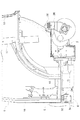
〔前ブラケット〕
図3から図5に示すように、前ブラケット24は、クラッチハウジング6から機体横外方に延出されている。前ブラケット24には、固定板27と、天板28と、一対の側板29と、が備えられている。固定板27は、クラッチハウジング6の横側部にボルト30によって固定されている。固定板27には、天板28及び一対の側板29が固定されている。天板28及び一対の側板29は、板状部材が略門型形状に折り曲げられて一体的に形成されている。
[Front bracket]
As shown in FIGS. 3 to 5, the
天板28のうち機体横外側寄りの部分には、前防振ゴム23が嵌め込まれる嵌込孔28aが形成されている。天板28の下面には、ボルト31に対応するナット32が溶接固定されている。
A
側板29は、天板28の前後両端部から下方に延出されている。側板29は、その下辺が機体横外側上がりに傾斜するように形成されている。すなわち、側板29は、その上下方向の長さが機体横外側に向かって短くなるように形成されている。
The
〔前防振ゴム〕
前防振ゴム23は、フロアパネル15にボルト固定されている。前防振ゴム23は、本体部23Aと、フランジ部23Bと、を有している。本体部23Aのうち軸部23aが嵌込孔28aに嵌め込まれた状態で、フランジ部23Bが天板28にボルト31によって固定されている。
[Pre-vibration rubber]
The front
〔突出板〕
前ブラケット24には、前ブラケット24から機体横外方に突出する突出板33(本発明に係る「取付け部」、「突出部」に相当)が設けられている。突出板33は、天板28の下面のうち嵌込孔28aよりも機体横外側の部分に固定されている。突出板33は、ウエイト34(本発明に係る「錘部材」に相当)が取り付けられる取付け面33Aを有している。取付け面33Aは、突出板33の下面に形成されている。
[Protruding plate]
The
〔当接板〕
前ブラケット24には、当接板35(本発明に係る「当接部」に相当)が設けられている。当接板35は、キャビン9の下部(例えば、フロアパネル15)が当接可能に構成されている。当接板35は、ウエイト34に対して前側に隣接する状態で、前ブラケット24の機体横外側端部に固定されている。当接板35は、板状部材が略クランク形状に折り曲げられて、上端部が下端部よりも機体横外側に位置するように形成されている。
[Abutment plate]
The
〔ウエイト〕
図3から図6に示すように、ウエイト34は、金属製(例えば、鉛)のブロックによって構成されている。ウエイト34は、前ブラケット24から機体横外方に突出する状態で、突出板33の下面(取付け面33A)にボルト36によって固定されている。ウエイト34(突出板33)は、前ブラケット24のうち前後幅方向の略中央部に配置されている。具体的には、ウエイト34(突出板33)は、ウエイト34(突出板33)の前後中心C1が前ブラケット24の前後中心C2に対して若干後側に片寄った位置に配置されている。
〔weight〕
As shown in FIGS. 3 to 6, the
ウエイト34には、ボルト36に対応する一対のボルト孔34aが、ウエイト34の左右中心C3に対して片寄った位置に形成されている。これにより、ウエイト34を一対のボルト孔34aが機体横外側寄りに位置する姿勢で突出板33に取り付けたり、あるいは、ウエイト34を一対のボルト孔34aが機体横内側寄りに位置する姿勢で突出板33に取り付けたりして、前ブラケット24に対するウエイト34の左右位置を変更することができる。
In the
ウエイト34は、取付け面33Aに対向する対向面34Aのうち一部(接触部34B)のみが取付け面33Aに接触する状態で、取付け面33Aに取り付けられている。対向面34Aには、対向面34Aのうち取付け面33Aに接触する接触部34Bと、対向面34Aのうち取付け面33Aに接触しない非接触部34Cと、が形成されている。接触部34Bは、対向面34Aの前後両端部に亘って、取付け面33A側に突出するように設けられている。
The
対向面34Aに直交する方向視(平面視)において、接触部34Bの面積は、対向面34Aの外周面積の半分以下である。この場合、平面視において、接触部34Bの面積は、対向面34Aの外周面積の3/4以下であると好ましい。ここで、対向面34Aの外周面積とは、平面視において、外縁34bに囲まれた領域の面積を意味している。
In a direction view (plan view) orthogonal to the facing
接触部34Bは、ウエイト34の左右中心C3(本発明に係る「錘部材におけるブラケットの延出方向の中心」に相当)よりも機体外側に位置している。この場合、接触部34Bは、ウエイト34における左右中心C3と機体外側端との間の中心C4よりも機体外側に位置していると好適である。
The
上下方向において、取付け面33Aに対するウエイト34の取付け位置H1と、前ブラケット24(天板28)に対する前防振ゴム23(フランジ部23B)の取付け位置H2とが、異なる位置に設定されている。本実施形態では、上下方向において、取付け位置H1が取付け位置H2よりも低い位置に設定されている。
In the vertical direction, the mounting position H1 of the
ウエイト34は、平面視で前防振ゴム23のうち本体部23A及びフランジ部23Bと重複する状態で設けられている。この場合、平面視において、外縁34bに囲まれた領域のうち1/10〜1/4の部分が前防振ゴム23のうち本体部23Aと重複していると好ましく、平面視において、外縁34bに囲まれた領域のうち1/7〜1/5の部分が前防振ゴム23のうち本体部23Aと重複していると更に好ましい。
The
〔前ブラケットの応答加速度と周波数との関係ついて〕
図7において、横軸は、周波数(Hz)を示し、縦軸は、前ブラケット24の応答加速度を示している。また、図7において、実線は、前ブラケット24の周波数毎の応答加速度をプロットした線であり、点線は、従来のブラケットの周波数毎の応答加速度をプロットした線である。
[Relationship between front bracket response acceleration and frequency]
In FIG. 7, the horizontal axis indicates the frequency (Hz), and the vertical axis indicates the response acceleration of the
ここで、図7に示すように、キャビン9の空間共鳴周波数やエンジンEの振動周波数は、一般的に180〜200Hzであることが知られている。そして、従来のブラケットでは、固有振動数が200Hz付近に存在しており、ブラケットの固有振動数が、キャビン9の空間共鳴周波数やエンジンEの振動周波数と一致して、キャビン9における振動や騒音が大きくなる場合がある。
Here, as shown in FIG. 7, it is known that the spatial resonance frequency of the
また、図7に示すように、従来のブラケットは、固有振動数200Hzを境に低周波数側の方が高周波数側よりも応答加速度(振動)が大きくなる傾向にあるところ、固有振動数200Hzよりも低周波数側の周波数帯においては、防振部材の振動伝達を十分に低減することができない。 Also, as shown in FIG. 7, in the conventional bracket, the response acceleration (vibration) tends to be larger on the low frequency side than on the high frequency side at the natural frequency of 200 Hz, whereas the natural frequency of 200 Hz In the frequency band on the low frequency side as well, the vibration transmission of the vibration isolation member can not be sufficiently reduced.
これに対して、前ブラケット24では、固有振動数が150Hz付近に設定されており、前ブラケット24の固有振動数を、キャビン9の空間共鳴周波数やエンジンEの振動周波数よりも小さくして、前ブラケット24を介してキャビン9に伝わる振動を低減することができる。また、前ブラケット24の固有振動数が従来のブラケットの固有振動数よりも小さくなる結果、前防振ゴム23の振動伝達を十分に低減することができる。この点からも、前ブラケット24を介してキャビン9に伝わる振動を低減することができる。
On the other hand, in the
〔別実施形態〕
(1)上記実施形態では、突出板33が天板28に固定されているが、本発明はこれに限定されない。例えば、突出板33又は天板28に長孔(図示省略)を形成して、この長孔を介して突出板33を天板28にボルト固定することにより、突出板33の位置を前後方向若しくは左右方向又はその両方に位置調節可能に構成してもよい。また、ウエイト34が突出板33を介さずに前ブラケット24に直接取り付けられていてもよい。
[Another embodiment]
(1) In the above embodiment, the projecting
(2)上記実施形態では、ウエイト34が前ブラケット24に取り付けられているが、これに代えて又はこれと共に、ウエイト34が後ブラケット26に取り付けられていてもよい。この場合、ウエイト34が後ブラケット26のうち後防振ゴム25よりも機体横外側の位置に、後ブラケット26から機体横外側に突出する状態で取り付けられていてもよい。
(2) In the above embodiment, the
(3)上記実施形態では、ウエイト34(突出板33)は、ウエイト34(突出板33)の前後中心C1が前ブラケット24の前後中心C2に対して若干後側に片寄った位置に配置されているが、本発明はこれに限定されない。
(3) In the above embodiment, the weight 34 (protruding plate 33) is disposed at a position where the front-rear center C1 of the weight 34 (projecting plate 33) is slightly offset to the front-rear center C2 of the
例えば、ウエイト34(突出板33)は、その前後中心C1が前ブラケット24の前後中心C2と一致する位置、すなわち、前ブラケット24のうち前後幅方向の中央部に配置されていてもよいし、あるいは、その前後中心C1が前ブラケット24の前後中心C2に対して若干前側に片寄った位置に配置されていてもよい。また、ウエイト34(突出板33)は、前ブラケット24の前後幅方向の前端部又は後端部に配置されていてもよい。
For example, the weight 34 (projecting plate 33) may be disposed at a position at which the longitudinal center C1 coincides with the longitudinal center C2 of the
(4)上記実施形態では、側板29は、その上下方向の長さが機体横外側に向かって短くなるように形成されているが、その上下方向の長さが同一となるように形成されていてもよい。
(4) In the above embodiment, the
(5)上記実施形態では、当接板35は、ウエイト34に対して前側に隣接する状態で設けられているが、ウエイト34に対して後側に隣接する状態で設けられていてもよい。また、当接板35が設けられていなくてもよい。
(5) In the above embodiment, the
(6)上記実施形態では、対向面34Aに直交する方向視(平面視)において、接触部34Bの面積は、対向面34Aの外周面積の半分以下であるが、接触部34Bの面積は、対向面34Aの外周面積よりも若干広くてもよい。
(6) In the above embodiment, the area of the
(7)上記実施形態では、接触部34Bは、ウエイト34の左右中心C3よりも機体外側に位置しているが、ウエイト34の左右中心C3よりも機体内側に位置していてもよいし、あるいは、ウエイト34の左右中心C3上に位置していてもよい。
(7) In the above embodiment, the
(8)上記実施形態では、上下方向において、取付け位置H1が取付け位置H2よりも低い位置に設定されているが、取付け位置H1が取付け位置H2よりも高い位置に設定されていてもよいし、あるいは、取付け位置H1と取付け位置H2とが同じ位置に設定されていてもよい。 (8) In the above embodiment, the mounting position H1 is set lower than the mounting position H2 in the vertical direction, but the mounting position H1 may be set higher than the mounting position H2. Alternatively, the mounting position H1 and the mounting position H2 may be set to the same position.
(9)上記実施形態では、ウエイト34は、平面視で前防振ゴム23のうち本体部23A及びフランジ部23Bと重複する状態で設けられているが、平面視で前防振ゴム23のうちフランジ部23Bのみと重複する状態で設けられていてもよいし、あるいは、平面視で前防振ゴム23と重複しない状態で設けられていてもよい。
(9) In the above embodiment, the
本発明は、キャビン付のトラクタの他、キャビン付のコンバインにも利用可能である。 The present invention is applicable not only to a tractor with a cabin but also to a combine with a cabin.
6 クラッチハウジング(機体フレーム)
9 キャビン
23 前防振ゴム(防振部材)
24 前ブラケット(ブラケット)
28 天板
29 側板
33 突出板(取付け部、突出部)
33A 取付け面
34 ウエイト(錘部材)
34A 対向面
34B 接触部
35 当接板(当接部)
C3 ウエイトの左右中心(錘部材におけるブラケットの延出方向の中心)
H1 取付け位置(取付け面に対する錘部材の取付け位置)
H2 取付け位置(ブラケットに対する防振部材の取付け位置)
6 Clutch housing (airframe frame)
9
24 Front bracket (bracket)
28
Left and right center of C3 weight (center of extension direction of bracket on weight member)
H1 Mounting position (Mounting position of weight member to mounting surface)
H2 mounting position (mounting position of anti-vibration member to bracket)
Claims (11)
前記ブラケットに、錘部材が設けられており、
前記錘部材は、前記ブラケットのうち前記防振部材よりも機体外側の位置に、前記ブラケットから機体外方に突出する状態で取り付けられており、
前記ブラケットに、前記錘部材が取り付けられる取付け面を有する取付け部が設けられており、
前記錘部材は、前記取付け面に対向する対向面のうち一部のみが前記取付け面に接触する状態で、前記取付け面に取り付けられている作業車。 A work vehicle in which a cabin is mounted and supported via a vibration isolation member on a bracket extended from the airframe frame to the outside of the airframe,
The bracket is provided with a weight member,
The weight member is attached to a position of the bracket on the outer side of the machine body than the vibration-proofing member in a state where the weight member protrudes outward from the bracket.
The bracket is provided with a mounting portion having a mounting surface to which the weight member is mounted,
The said weight member is a working vehicle attached to the said attachment surface in the state which contacts only the said attachment surface among only the opposing surfaces which oppose the said attachment surface.
前記ブラケットに、錘部材が設けられており、
前記錘部材は、前記ブラケットのうち前記防振部材よりも機体外側の位置に、前記ブラケットから機体外方に突出する状態で取り付けられており、
前記錘部材は、平面視で前記防振部材と重複する状態で設けられ、
前記ブラケットに、前記ブラケットから機体外方に突出する突出部が設けられており、
前記突出部に、前記錘部材が取り付けられている作業車。 A work vehicle in which a cabin is mounted and supported via a vibration isolation member on a bracket extended from the airframe frame to the outside of the airframe,
The bracket is provided with a weight member,
The weight member is attached to a position of the bracket on the outer side of the machine body than the vibration-proofing member in a state where the weight member protrudes outward from the bracket.
The weight member is provided so as to overlap with the anti-vibration member in plan view ,
The bracket is provided with a protrusion which protrudes from the bracket to the outside of the machine,
The work vehicle in which the weight member is attached to the protrusion .
前記側板は、その上下方向の長さが機体外側に向かって短くなるように形成されている請求項1から8の何れか一項に記載の作業車。 The bracket includes a top plate to which the anti-vibration member is attached, and a pair of side plates provided on both ends of the top plate in the width direction orthogonal to the extending direction of the bracket in plan view. ,
The work vehicle according to any one of claims 1 to 8 , wherein the side plate is formed such that the length in the vertical direction is shortened toward the outer side of the machine body.
Priority Applications (3)
| Application Number | Priority Date | Filing Date | Title |
|---|---|---|---|
| US15/172,506 US10099728B2 (en) | 2015-08-07 | 2016-06-03 | Work vehicle |
| EP16173161.7A EP3127790B1 (en) | 2015-08-07 | 2016-06-06 | Work vehicle |
| CN201620546895.3U CN205836976U (en) | 2015-08-07 | 2016-06-07 | Operation Van |
Applications Claiming Priority (2)
| Application Number | Priority Date | Filing Date | Title |
|---|---|---|---|
| JP2015157357 | 2015-08-07 | ||
| JP2015157357 | 2015-08-07 |
Publications (3)
| Publication Number | Publication Date |
|---|---|
| JP2017036032A JP2017036032A (en) | 2017-02-16 |
| JP2017036032A5 JP2017036032A5 (en) | 2019-02-07 |
| JP6541614B2 true JP6541614B2 (en) | 2019-07-10 |
Family
ID=58048387
Family Applications (1)
| Application Number | Title | Priority Date | Filing Date |
|---|---|---|---|
| JP2016093324A Active JP6541614B2 (en) | 2015-08-07 | 2016-05-06 | Work vehicle |
Country Status (2)
| Country | Link |
|---|---|
| US (1) | US10099728B2 (en) |
| JP (1) | JP6541614B2 (en) |
Families Citing this family (4)
| Publication number | Priority date | Publication date | Assignee | Title |
|---|---|---|---|---|
| KR102644709B1 (en) * | 2017-02-28 | 2024-03-06 | 에이치디현대인프라코어 주식회사 | Cabin assembly of construction equipment |
| CA3059775A1 (en) | 2017-04-13 | 2018-10-18 | Ovid Therapeutics Inc. | Methods of treating developmental encephalopathies |
| JP7236942B2 (en) * | 2019-06-19 | 2023-03-10 | 株式会社小松製作所 | work vehicle |
| US11486460B2 (en) | 2019-08-27 | 2022-11-01 | Deere & Company | Work vehicle with tuned mass dampers |
Family Cites Families (7)
| Publication number | Priority date | Publication date | Assignee | Title |
|---|---|---|---|---|
| JPS61129373A (en) * | 1984-11-26 | 1986-06-17 | Kubota Ltd | Can support structure |
| US4650242A (en) | 1984-11-26 | 1987-03-17 | Kubuto, Ltd. | Tractor cabin |
| GB0021140D0 (en) | 1999-11-30 | 2000-10-11 | Kubota Kk | Dynamic dampers, and a damping support apparatus for a vehicle body using the dynamic dampers |
| JP3527446B2 (en) * | 1999-12-06 | 2004-05-17 | 株式会社クボタ | Traveling vehicle with cabin |
| JP4851921B2 (en) * | 2006-12-06 | 2012-01-11 | 株式会社クボタ | Work vehicle with cabin |
| KR20080092838A (en) | 2007-04-12 | 2008-10-16 | 가부시끼 가이샤 구보다 | Vehicle with cabin |
| JP5137859B2 (en) | 2009-01-14 | 2013-02-06 | ヤンマー株式会社 | Work vehicle with cabin |
-
2016
- 2016-05-06 JP JP2016093324A patent/JP6541614B2/en active Active
- 2016-06-03 US US15/172,506 patent/US10099728B2/en active Active
Also Published As
| Publication number | Publication date |
|---|---|
| JP2017036032A (en) | 2017-02-16 |
| US20170036707A1 (en) | 2017-02-09 |
| US10099728B2 (en) | 2018-10-16 |
Similar Documents
| Publication | Publication Date | Title |
|---|---|---|
| JP6541614B2 (en) | Work vehicle | |
| CN109263456B (en) | Vehicle body structure | |
| JP6489140B2 (en) | Lower body structure of the vehicle | |
| JP5747270B2 (en) | Installation structure of important safety parts at the rear of the car | |
| JP2004217108A (en) | Front body structure of automobile | |
| JP6455654B2 (en) | Vehicle power plant mounting structure | |
| CN110356215B (en) | Support structure for drive source | |
| JP5622045B2 (en) | Powertrain support device | |
| JP6754006B2 (en) | Torque rod mounting structure | |
| WO2016076046A1 (en) | Front structure of vehicle body | |
| JP6652848B2 (en) | Body front structure | |
| JP2002200924A (en) | Power plant support structure | |
| KR101124975B1 (en) | Cowl under cover panel for vehicle | |
| EP3127790B1 (en) | Work vehicle | |
| JPH11348689A (en) | Car body structure | |
| JP2004330942A (en) | Engine mount structure for automobile | |
| JP7083035B2 (en) | Subframe structure | |
| JPH0443172A (en) | Engine mount installation structure of automobile | |
| JP7428591B2 (en) | car body structure | |
| JP6897506B2 (en) | mount | |
| JP6515948B2 (en) | Powertrain mounting device | |
| JP2000016334A (en) | Forward structure of convertible vehicle body | |
| KR101163802B1 (en) | Reinforcing Assembly for rear cross member | |
| WO2020065899A1 (en) | Subframe structure | |
| JP2013119318A (en) | Vehicle body front structure |
Legal Events
| Date | Code | Title | Description |
|---|---|---|---|
| A621 | Written request for application examination |
Free format text: JAPANESE INTERMEDIATE CODE: A621 Effective date: 20180626 |
|
| A521 | Written amendment |
Free format text: JAPANESE INTERMEDIATE CODE: A523 Effective date: 20181220 |
|
| A871 | Explanation of circumstances concerning accelerated examination |
Free format text: JAPANESE INTERMEDIATE CODE: A871 Effective date: 20181220 |
|
| A975 | Report on accelerated examination |
Free format text: JAPANESE INTERMEDIATE CODE: A971005 Effective date: 20190109 |
|
| A131 | Notification of reasons for refusal |
Free format text: JAPANESE INTERMEDIATE CODE: A131 Effective date: 20190115 |
|
| A521 | Written amendment |
Free format text: JAPANESE INTERMEDIATE CODE: A523 Effective date: 20190313 |
|
| A131 | Notification of reasons for refusal |
Free format text: JAPANESE INTERMEDIATE CODE: A131 Effective date: 20190326 |
|
| A521 | Written amendment |
Free format text: JAPANESE INTERMEDIATE CODE: A523 Effective date: 20190424 |
|
| TRDD | Decision of grant or rejection written | ||
| A01 | Written decision to grant a patent or to grant a registration (utility model) |
Free format text: JAPANESE INTERMEDIATE CODE: A01 Effective date: 20190514 |
|
| A61 | First payment of annual fees (during grant procedure) |
Free format text: JAPANESE INTERMEDIATE CODE: A61 Effective date: 20190611 |
|
| R150 | Certificate of patent or registration of utility model |
Ref document number: 6541614 Country of ref document: JP Free format text: JAPANESE INTERMEDIATE CODE: R150 |