JP6534543B2 - Cutting machine - Google Patents
Cutting machine Download PDFInfo
- Publication number
- JP6534543B2 JP6534543B2 JP2015053913A JP2015053913A JP6534543B2 JP 6534543 B2 JP6534543 B2 JP 6534543B2 JP 2015053913 A JP2015053913 A JP 2015053913A JP 2015053913 A JP2015053913 A JP 2015053913A JP 6534543 B2 JP6534543 B2 JP 6534543B2
- Authority
- JP
- Japan
- Prior art keywords
- cutting machine
- controller
- motor
- housing portion
- brushless motor
- Prior art date
- Legal status (The legal status is an assumption and is not a legal conclusion. Google has not performed a legal analysis and makes no representation as to the accuracy of the status listed.)
- Active
Links
Images


Description
この発明は、切断機本体を上下に揺動させることにより、切断機本体により回転される回転刃具により被切断材を切断する定置式または卓上型の切断機に関する。 The present invention relates to a stationary or bench type cutting machine that cuts a material to be cut by a rotary blade that is rotated by the cutting machine body by swinging the cutting machine body up and down.
従来、丸鋸や砥石などの円形の切断刃(以下「回転刃具」と称する)を回転させて被切断材を切断する切断機が知られている。このような切断機には、地面に置いて使用される定置式の切断機や、卓上で使用される卓上型切断機などがある。このような切断機は、駆動源としてのモータが内蔵される。モータにより発生させた回転駆動力は、減速ユニットを介して出力軸に伝達される。出力軸には回転刃具が取り付けられている。回転刃具は、被切断材を切断可能に出力軸と一体に回転する。 BACKGROUND Conventionally, there is known a cutting machine that cuts a material to be cut by rotating a circular cutting blade (hereinafter, referred to as a "rotating blade") such as a circular saw or a grindstone. Such cutting machines include stationary cutting machines that are used on the ground and tabletop cutting machines that are used on a desktop. Such a cutting machine incorporates a motor as a drive source. The rotational drive force generated by the motor is transmitted to the output shaft via the reduction gear unit. A rotary blade is attached to the output shaft. The rotary blade rotates integrally with the output shaft so as to cut the material to be cut.
ところで、電動工具にあっては、駆動源にブラシレスモータを利用するものがある。このようなブラシレスモータは、FET(Field effect transistor)などを搭載したコントローラにより回転駆動が制御されている。コントローラには、ブラシレスモータの巻線に供給する電力が流れる。このコントローラ自体も、ブラシレスモータの巻線と同様に発熱する。このため、このブラシレスモータの回転駆動を制御するコントローラにあっても、ブラシレスモータの巻線と同様に冷却することが求められている。 By the way, there are some electric tools that use a brushless motor as a drive source. The rotational drive of such a brushless motor is controlled by a controller equipped with an FET (Field Effect Transistor) or the like. Power is supplied to the windings of the brushless motor through the controller. The controller itself generates heat as well as the windings of the brushless motor. Therefore, even in the controller that controls the rotational drive of the brushless motor, it is required to cool the same as the windings of the brushless motor.
他方、上記した切断機にあっては、切断中に被切断材から切り粉が飛散される。このような切り粉は、被切断材から飛散されて空中を舞った後に、自重で落下して切断機に降りかかることが多い。このため、このような切断機にあっては、飛散される切り粉が降りかかる工夫を施すことが求められている。 On the other hand, in the above-mentioned cutting machine, chips are scattered from the material to be cut during cutting. Such swarf is often scattered from the material to be cut and flies in the air, and then falls by its own weight and often falls on the cutting machine. For this reason, in such a cutting machine, it is required to devise a device in which the swarf to be scattered falls.
本発明は、このような事情に鑑みなされたものであって、本発明が解決しようとする課題は、被切断材を切断する定置式または卓上型の切断機において、降りかかる切り粉の浸入をさせないようにしながら、ブラシレスモータの回転駆動を制御するコントローラを良好に冷却できるようにすることにある。 The present invention has been made in view of such circumstances, and the problem to be solved by the present invention is that in a stationary or table-top type cutting machine for cutting a material to be cut, the falling chips do not enter While maintaining good cooling of the controller that controls the rotational drive of the brushless motor.
上記した課題を解決するにあたって、本発明に係る切断機は次の手段をとる。すなわち、第1の発明に係る切断機は、回転刃具を回転させて被切断材を切断する定置式または卓上型の切断機であって、回転駆動力を発生させるモータと、前記モータの回転駆動を制御するコントローラと、前記コントローラを収容するコントローラハウジング部と、を有し、前記コントローラハウジング部には、該コントローラハウジング部の内外に通気可能な通気開口部が設けられており、前記通気開口部の配設箇所は、前記コントローラと対面し、且つ、該コントローラの下側に設定されている、という構成である。 In order to solve the above-mentioned subject, the cutting machine concerning the present invention takes the following means. That is, the cutting machine according to the first aspect of the present invention is a stationary or table-top type cutting machine that cuts a material to be cut by rotating a rotary blade, comprising: a motor generating rotational driving force; and rotational driving of the motor A controller housing portion for controlling the controller, and a controller housing portion for housing the controller, the controller housing portion being provided with a vent opening portion capable of ventilating the inside and the outside of the controller housing portion, the vent opening portion The arrangement position of is set to face the controller and is set on the lower side of the controller.
この第1の発明に係る切断機によれば、コントローラハウジング部には、コントローラハウジング部の内外に通気可能な通気開口部が設けられている。この通気開口部の配設箇所は、コントローラと対面しているので、通気開口部から入る外気はコントローラに直ぐに当たることとなる。また、この通気開口部の配設箇所は、コントローラの下側に設定されている。つまり、通気開口部は、下向きになっているので、切り粉が切断機に降りかかったとしても切り粉が通気開口部から入ってしまうことが無くなる。したがって、この第1の発明に係る切断機によれば、降りかかる切り粉の浸入をさせないようにしながら、ブラシレスモータの回転駆動を制御するコントローラを良好に冷却することができる。 According to the cutting machine of the first aspect of the present invention, the controller housing portion is provided with the vent opening portion which can ventilate inside and outside of the controller housing portion. The arrangement position of the vent opening faces the controller, so that the outside air entering from the vent opening will immediately hit the controller. Moreover, the arrangement | positioning location of this ventilation opening part is set below the controller. That is, since the ventilation opening is directed downward, no chips will enter from the ventilation opening even if the chips fall on the cutting machine. Therefore, according to the cutting machine according to the first aspect of the present invention, the controller for controlling the rotational drive of the brushless motor can be favorably cooled while preventing the infiltration of the falling chips.
また、第2の発明に係る切断機は、前記第1の発明に係る切断機において、前記コントローラハウジング部は、上下方向の寸法に対して左右方向の寸法が相対的に長くなるように設定されている、という構成である。ちなみに、前記上下方向は、切断機本体の切断揺動方向(回転刃具が揺動する方向)に略一致する方向である。また、前記左右方向は、回転刃具を回転させる出力軸が延在される方向(回転刃具の回転軸線が延びる方向)に一致する方向である。 A cutting machine according to a second aspect of the present invention is the cutting machine according to the first aspect, wherein the controller housing portion is set so that the dimension in the left-right direction is relatively long with respect to the dimension in the vertical direction. The configuration is Incidentally, the vertical direction is a direction substantially corresponding to the cutting and rocking direction of the cutting machine main body (the direction in which the rotary blade is rocked). Further, the left-right direction is a direction that coincides with the direction in which the output shaft for rotating the rotary blade extends (the direction in which the rotation axis of the rotary blade extends).
この第2の発明に係る切断機によれば、コントローラハウジング部は、上下方向の寸法に対して左右方向の寸法が相対的に長くなるように設定されているので、コントローラハウジング部の上下方向の長さを抑えることができる。これによって、切断機本体の上下方向の嵩張りを抑えることができて、切断機としてのコンパクト化を図ることができる。なお、コントローラは、半導体チップが載せられた基板をモールド成形した平板ブロック形(厚みを有する平板形)にて形成される。また、このようなコンパクト化を図るにあたっては、コントローラの最も広い面がモータのモータ軸線方向と平行となるようにコントローラハウジング部に支持される、ことなどが挙げられる。 According to the cutting machine of the second aspect of the invention, the controller housing portion is set such that the dimension in the left-right direction is relatively long with respect to the dimension in the vertical direction. The length can be reduced. By this, the bulkiness of the cutting machine main body in the vertical direction can be suppressed, and downsizing of the cutting machine can be achieved. The controller is formed in a flat plate block shape (flat plate shape having a thickness) obtained by molding a substrate on which a semiconductor chip is mounted. Further, in order to achieve such compactification, it is cited that the widest surface of the controller is supported by the controller housing portion so as to be parallel to the motor axial direction of the motor.
また、第3の発明に係る切断機は、前記第2の発明に係る切断機において、前記回転刃具が取り付けられる出力軸と、前記モータを内装するモータハウジング部と、を有し、前記コントローラハウジング部は、前記出力軸を基準にして前記モータハウジング部側に突き出されるように設定されている、という構成である。なお、このモータハウジング部側とは、回転刃具配置側とは逆側となる所謂モータ側である。 A cutting machine according to a third aspect of the present invention is the cutting machine according to the second aspect, further comprising: an output shaft to which the rotary blade is attached, and a motor housing portion for mounting the motor therein, the controller housing The unit is configured to be protruded toward the motor housing unit with reference to the output shaft. The motor housing portion side is a so-called motor side which is the opposite side to the rotary blade arrangement side.
この第3の発明に係る切断機によれば、コントローラハウジング部は、出力軸を基準にしてモータハウジング部側に突き出されるように設定されているので、コントローラハウジング部の出力軸側への嵩張りを抑えることができる。これによって、使用者の出力軸側の視認領域を確保することができて、被切断材を切断する際の作業を行い易くすることができる。なお、このように突き出されるコントローラハウジング部に収容されるコントローラは、切断機本体の揺動下死点にて上面視した場合にモータ軸と重なる位置に配置設定されている。 According to the cutting machine of the third aspect of the invention, the controller housing portion is set so as to protrude toward the motor housing portion with reference to the output shaft. You can suppress the tension. As a result, it is possible to secure a visual recognition area on the side of the output shaft of the user, which makes it easy to carry out the work when cutting the material to be cut. The controller housed in the controller housing portion thus projected is disposed and set so as to overlap the motor shaft when viewed from above at the swinging bottom dead center of the cutting machine main body.
また、第4の発明に係る切断機は、前記第1から前記第3のいずれかの発明に係る切断機において、前記コントローラは、前記モータハウジング部に対して相対的に上側に配置されている、という構成である。ちなみに、前記コントローラを収容する前記コントローラハウジング部も、前記モータハウジング部に対して相対的に上側に配置されている、こととなる。この第4の発明に係る切断機によれば、コントローラおよびコントローラハウジング部は、モータハウジング部に対して相対的に上側に配置されているので、デッドスペースとなり易いモータハウジング部の上側を有効活用することができる。これによって、切断機全体としてのコンパクト化を図ることができる。 A cutting machine according to a fourth invention is the cutting machine according to any one of the first to third inventions, wherein the controller is disposed on the upper side relative to the motor housing portion. , Is a configuration. Incidentally, the controller housing portion that accommodates the controller is also disposed on the upper side relative to the motor housing portion. According to the cutting machine according to the fourth aspect of the invention, the controller and the controller housing portion are disposed on the upper side relative to the motor housing portion, so that the upper side of the motor housing portion susceptible to dead space is effectively utilized. be able to. This makes it possible to make the entire cutting machine compact.
また、第5の発明に係る切断機は、前記第1から前記第4のいずれかの発明に係る切断機において、前記通気開口部は、該通気開口部から入った外気が前記コントローラの一面全域を通過して流れるように、該コントローラの該一面全域の上流位置に対面して設けられている、という構成である。この第5の発明に係る切断機によれば、通気開口部はコントローラの一面全域の上流位置に対面して設けられているので、通気開口部から入った外気はコントローラの一面全域を通過して流れる。これによって、冷却風を効率良く利用してコントローラを冷却することができる。 A cutting machine according to a fifth aspect of the present invention is the cutting machine according to any of the first to fourth aspects, wherein the ventilation opening portion is an entire area of the controller in which the outside air entered from the ventilation opening portion is , And is disposed facing the upstream position of the entire surface of the controller. According to the cutting machine according to the fifth aspect of the present invention, the ventilation opening is provided facing the upstream position of the entire area of one surface of the controller, so the outside air entering from the ventilation opening passes through the whole area of the controller Flow. Thereby, the controller can be cooled by efficiently using the cooling air.
また、第6の発明に係る切断機は、前記第1から前記第5のいずれかの発明に係る切断機において、前記モータは、ブラシレスモータにて構成され、前記コントローラには、前記ブラシレスモータの回転駆動および回生制動のいずれも制御する制御処理装置が含まれている、という構成である。この第6の発明に係る切断機によれば、コントローラにはブラシレスモータの回転駆動および回生制動のいずれも制御する制御処理装置が含まれているので、ブラシレスモータの回転に関する駆動および制動に関する制御を行うことができる。これによって、回転刃具の回転が的確に行えるようになり、利便性が高められた切断機とすることができる。 A cutting machine according to a sixth aspect of the present invention is the cutting machine according to any of the first to fifth aspects, wherein the motor is a brushless motor, and the controller includes the brushless motor. A control processing device that controls both rotational driving and regenerative braking is included. According to the cutting machine according to the sixth aspect of the invention, the controller includes the control processing device for controlling both the rotational drive and the regenerative braking of the brushless motor. It can be carried out. By this, rotation of the rotary blade can be accurately performed, and a cutting machine with improved convenience can be obtained.
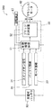
以下、本発明に係る切断機を実施するための形態について、図1〜図8を参照しながら説明する。図1は、保管時の切断機10を右側から視た全体側面図である。図2は、使用時の切断機10を右側から視た全体側面図である。図3は、図1の切断機10を前側から視た全体正面図である。図4は、図1の切断機10を上側から視た全体上面図である。図5は、図1の切断機10を左側から視た全体側面図である。図6は、前側から視た切断機本体20を一部切り欠いて示す一部切欠き断面図である。なお、図示にて規定される上下前後左右の方向は、使用者の使用状況に鑑みて設定される方向である。具体的には、上下方向は回転刃具Bの揺動方向に略一致し、左右方向は回転刃具Bの回転軸線に一致している。また、この切断機10における前側とは、切断機10を使用する使用者が居る側で規定されている。
EMBODIMENT OF THE INVENTION Hereinafter, the form for implementing the cutting machine which concerns on this invention is demonstrated, referring FIGS. 1-8. FIG. 1 is an overall side view of the
図示される切断機10は、地面に置かれて使用される定置式の切断機として構成される。この切断機10は、回転刃具Bを回転させて被切断材を切断する。この切断機10は、電源として2つの充電式バッテリ90が利用される切断機であり、駆動源としてブラシレスモータ62が利用される切断機となっている。図1および図2に示すように、切断機10は、大まかに分けて、ベース11と切断機本体20とを有する。ベース11は地面に置かれる支持台である。ベース11の上面はテーブル面12として設定される。テーブル面12には、切断機10にて切断される被切断材が載せられる。テーブル面12には、載せられた被切断材を後側から当接支持するフェンス13が設けられている。フェンス13は固定部材14によりテーブル面12に固定されている。
The illustrated cutting
テーブル面12には、載せられた被切断材を前側から当接支持するバイスプレート15が設けられている。バイスプレート15は固定ハンドル16によってテーブル面12に固定されている。バイスプレート15は、固定ハンドル16の固定を解除することにより、テーブル面12に対して相対的に動かすことができる。テーブル面12の後端部分には、切断機本体20を連結支持する支持連結部17が設けられている。支持連結部17は、テーブル面12から上側にブラケット形に突き出されるようにして設けられている。支持連結部17の上端部分には、切断機本体20を回転可能に軸支持する回動軸部18が設けられている。回動軸部18には、切断機本体20の回動支持部215の下端が連結されて支持している。
The
切断機本体20は、回動軸部18を回動支点にして、回動支持部215と共にベース11に対して上下に揺動することができる。後にも説明するが、切断機本体20を下側へ動かしていくと回転刃具Bはテーブル面12に載せられた被切断材に当たる。ここで、回転する回転刃具Bは、被切断材を切断するように当たることとなる。なお、回転刃具Bとしては、例えば円形の切断砥石により設定される。切断機本体20は、上記したように回転刃具Bを回転させるモータ部61とギヤ部71とを有する。切断機本体20は、テーブル面12に対して相対的に上下揺動可能にベース11に支持されている。
The cutting machine
切断機本体20は、図3および図4に示すように、概略、ハンドル部21と、モータ部61と、ギヤ部71とを有する。モータ部61は、ハンドル部21に対して相対的に左側に配置される。また、ギヤ部71は、ハンドル部21に対して相対的に右側に配置される。なお、モータ部61およびギヤ部71の前後位置としては、ハンドル部21の前後の略中間位置に設定されている。これらのハンドル部21と、モータ部61と、ギヤ部71とは、それぞれのハウジング210,610,710同士を螺子留めすることにより、一体の切断機本体20をなしている。
As shown in FIGS. 3 and 4, the cutting machine
ハンドル部21は、ハンドルハウジング210を有して設定される。このハンドルハウジング210には、図5に示すように、2つのグリップ部23,25が設けられている。第1グリップ部23は、モータ部61に対して相対的に前側に設定されている。この第1グリップ部23は、切断機本体20を上下に揺動操作(切断上下操作)する際に手で握られる箇所である。このため、第1グリップ部23は、切断機本体20の上下の揺動操作と共に、切断機本体20のオンオフ操作を行うための操作トリガ242が設けられている。操作トリガ242は、操作ボタン241の押下の後に引き操作可能となっている。操作トリガ242が引き操作されると、この操作トリガ242から後に説明するコントローラ50にスイッチオン信号が送信される。
The
これに対し、第2グリップ部25は、モータ部61に対して相対的に上側に設定されている。第2グリップ部25は、主に切断機10を持ち運びする際に手で握られる箇所である。なお、切断機10を持ち運ぶ際、ベース11に対して切断機本体20が揺動しないように、留めチェーン29により、ベース11と切断機本体20との互いの相対的な動きが留められる。つまり、留めチェーン29は、一端がベース11に取り付けられていると共に、他端が第1グリップ部23の前端に取り付けられている。
On the other hand, the
ところで、ハンドルハウジング210には、2つ充電式バッテリ90が装着される2つのバッテリ装着部34が設けられている。すなわち、第2グリップ部25の後端251には、装着ベース31が設けられている。装着ベース31は、第2グリップ部25の後端251に対面するように設定される右側装着部341と、右側装着部341の左隣に右側装着部341と並列して設定される左側装着部342とが設けられる。装着ベース31は、第2グリップ部25の後端251から左側に向けて、左側装着部342の分だけ突出された形状となっている。この装着ベース31には、充電式バッテリ90が装着される装着面が後側に向くように2つのバッテリ装着部341,342が左右に並列して設けられる。これらのバッテリ装着部341,342には、定格電圧が18Vに設定される同一の充電式バッテリ90が、上から下へスライドさせることにより装着できるようになっている。
The
このように並列されるバッテリ装着部341,342に装着された2つの充電式バッテリ90の左右範囲の長さは、装着ベース31の左右範囲の長さに収まっている。ちなみに、この装着ベース31の左端縁312は、モータハウジング610の左側面611よりも左側に突出されている。また、装着ベース31の右端縁311は、第2グリップ部25の右側縁253から僅かに右側に突出されるに留まっている。このため、装着ベース31の右端縁311とブレードケース75との間には、適宜の空間が設けられている。なお、このハンドルハウジング210には、コントローラハウジング部41が設けられるものとなっているが、このコントローラハウジング部41に関しては、次のモータ部61およびギヤ部71の説明の後に詳述する。
The lengths of the left and right ranges of the two
モータ部61は、図6に示すように、モータハウジング610を有して設定される。モータハウジング610は、ハンドルハウジング210の左隣にてハンドルハウジング210に螺子留めされている。モータハウジング610は有底筒形の外形をなしている。モータハウジング610の内部615には、ブラシレスモータ62が装置される。ブラシレスモータ62は、切断機本体20の駆動源であり、回転駆動力を発生させるモータである。このブラシレスモータ62は、詳しくはブラシレスDCモータにて構成され、U相、V相、W相を有する3相モータで構成される。ブラシレスモータ62は、概略、モータ軸63と、回転子64と、巻線65と、インシュレータ66と、センサ基板67とを有する。モータ軸63は、回転子64の回転軸である。モータ軸63は、モータハウジング610の内部615で左右に延びるように配置されている。
The
モータ軸63は、ベアリング631,632にて回転可能に支持されている。具体的には、左ベアリング631は、モータ軸63の左端を回転可能に支持する。この左ベアリング631はモータハウジング610に支持される。また、右ベアリング632は、モータ軸63の右端近傍を回転可能に支持する。この右ベアリング632はギヤハウジング710に支持される。なお、このモータ軸63の右端は、平歯車に形成される入力ギヤ633が設定されている。この入力ギヤ633は、モータ軸63と一体に回転してギヤ部71(減速ギヤ72)に回転駆動を入力する。なお、モータ軸63の中間部分には、後に説明する冷却ファン35が取り付けられている。
The
回転子64は、回転軸となるモータ軸63に支持されている。巻線65とインシュレータ66は、回転子64の周囲に配置され、モータハウジング610に支持されている。巻線65は、電流が流されることにより磁場を発生する。この巻線65は、U相、V相、W相の各相ごとで設定される。インシュレータ66は巻線65と電気的に絶縁している。センサ基板67は、モータハウジング610に支持されている。このセンサ基板67は、回転子64の左端に対面して配置されている。センサ基板67は、ホール素子を利用して構成され、回転子64の回転に関する検出を行う。このセンサ基板67は、後に説明するコントローラ50と電気的に接続され、回転子64の回転に基づいてコントローラ50の制御処理装置51に位置信号を送信する。
The
モータ軸63には、冷却ファン35が取り付けられている。冷却ファン35は遠心式送風機で構成される。冷却ファン35の周囲にはバッフルプレート36が設けられている。バッフルプレート36は、モータ軸63と一体に回転する冷却ファン35に気流を発生させる。冷却ファン35は、バッフルプレート36の形状により、冷却ファン35の図示左側から吸入し図示右側に吐出する流れを発生する。この冷却ファン35により発生させる冷却風は、ブラシレスモータ62およびコントローラ50を冷却する。このため、モータハウジング610にはモータ側吸気部69が設けられており、後に説明するコントローラハウジング部41には風窓47が設けられている。
A cooling
モータ側吸気部69は、図5に示すようにモータハウジング610の左側面611に設けられている。モータ側吸気部69は、モータハウジング610の内外を連通するスリット形の開口形状が複数設けられることにより設定される。つまり、冷却ファン35の回転により発生された気流は、モータ側吸気部69から外気を吸入する。吸入された外気は、第1冷却風としてブラシレスモータ62に対して左から右へ通過して冷却ファン35に入り、その後に次に説明するギヤ部71へ向かって吐出される。この際、第1冷却風W1は、ブラシレスモータ62を通過する際に巻線65を含むブラシレスモータ62を冷却することとなる。なお、コントローラ50を冷却する第2冷却風W2については後に詳述することとする。
The motor-
ギヤ部71は、図6に示すように、ギヤハウジング710を有して設定される。ギヤハウジング710は、ハンドルハウジング210の右隣にてハンドルハウジング210に螺子留めされている。ギヤハウジング710の内部には、減速ギヤ72および出力軸73が装置されている。減速ギヤ72は、回転軸となる出力軸73と一体にされている。減速ギヤ72は、入力ギヤ633と噛合する平歯車である。このため、モータ軸63の回転駆動は、入力ギヤ633から噛合される減速ギヤ72に伝達されることにより、出力軸73を回転させる。出力軸73は、ベアリング731,732にて回転可能に支持されている。具体的には、左ベアリング731は、出力軸73の左端を回転可能に支持する。この左ベアリング731はギヤハウジング710に支持される。また、右ベアリング732は、出力軸73の右端近傍を回転可能に支持する。この右ベアリング732はベアリングボックス74に支持される。
The
出力軸73の右端は、ブレードケース75の内部に露出されている。この出力軸73の右端には、フランジ形の固定部材を介して回転刃具Bが取り付けられる。ブレードケース75は、回転刃具Bの周囲を覆う形状に形成される。このブレードケース75は、ギヤハウジング710に螺子留めされて固定されている。このブレードケース75には、ブレードケース75に対して相対的に変位可能な可動カバー76が取り付けられている。なお、出力軸73に対して回転刃具Bの付け替えを行うにあたっては、ギヤハウジング710に設けられたストッパ781を、付勢ばね782の付勢に抗して減速ギヤ72に設けられる嵌合孔783に嵌合させ、ギヤハウジング710に対する出力軸73の相対回転を規制する。このような出力軸73の固定により、上記したフランジ形の固定部材の固定を解除および締結が可能となる。
The right end of the
ところで、第2グリップ部25の下側には、コントローラ部40が設けられている。図7は、左側から視た切断機本体20を一部切り欠いて示す一部切欠き断面図である。図8は、図7の(VIII)-(VIII)断面矢視を示す断面図である。図7および図8に示すように、コントローラ部40は、コントローラハウジング部41にコントローラ50を収容して構成される。このコントローラ50は、図7に示すように側面視すると前後に延びながら上下に厚みを有する形状にて形成されている。また、このコントローラ50は、図8に示すように上面視すると前後に延びながら左右に拡がりを有する形状にて形成されている。つまり、コントローラ50は、半導体チップが載せられた基板をモールド成形した平板ブロック形(厚みを有する平板形)にて形成される。このコントローラ50は、ブラシレスモータ62と充電式バッテリ90との間で図9に示す駆動システム500を構成する。
The
図9は、ブラシレスモータ62の駆動システム500を模式的に示すブロック図である。図9に示すように、コントローラ50は、制御処理装置51とブリッジ回路装置52とを有し、ブラシレスモータ62の回転駆動を制御する。制御処理装置51は、CPU(Central Processing Unit)および適宜の記憶媒体を有して構成される。ブリッジ回路装置52は、ブラシレスモータ62を駆動させるためのスイッチング回路として構成される。この制御処理装置51は、ブラシレスモータ62に回転駆動させるための制御を行うほか、モータ軸63の回転を制動させる回生制動の制御も行うものとなっている。ブリッジ回路装置52は、スイッチング素子としてのFET(Field effect transistor)を有して構成される。つまり、制御処理装置51は、ブリッジ回路装置52の制御を行うことによってブラシレスモータ62を回転駆動および回生制動させる。ちなみに、制御処理装置51は、センサ基板67による回転子64の回転に関する検出に基づいて制御処理する。また、この制御処理装置51には、充電式バッテリ90の電圧や温度などのバッテリ情報が送られている。また、この制御処理装置51には、ブラシレスモータ62の温度などのモータ情報が送られている。
FIG. 9 is a block diagram schematically showing a
ところで、コントローラハウジング部41は、コントローラ50の外周形状に対応した形状が選択されている。コントローラハウジング部41は、平板ブロック形のコントローラ50を収容可能とする内部空間410を有して設定される。つまり、コントローラハウジング部41は、コントローラ50の外周を覆うような形状にて、ハンドルハウジング210と一体に形成されている。このコントローラ50は、内部空間410にて固定部材43を介してコントローラハウジング部41に固定保持されている。ここで、コントローラ50は、平板ブロック形の最も広い下面53がブラシレスモータ62のモータ軸63の軸線方向と平行となるように、コントローラハウジング部41に支持されている。
By the way, the shape corresponding to the outer peripheral shape of the
コントローラハウジング部41の配設箇所としては、次のように設定されている。すなわち、コントローラハウジング部41は、第2グリップ部25とモータハウジング610との間に配置されるように設定されている。具体的には、図7に示す上下の配置関係で言えば、コントローラハウジング部41は、第2グリップ部25の真下の位置に配置されている。また、コントローラハウジング部41は、モータハウジング610の真上の位置に配置されている。このように、コントローラハウジング部41に収容されるコントローラ50は、モータハウジング610に対して相対的に上側に配置されている。コントローラハウジング部41の前後範囲で言えば、図7に示すように、コントローラハウジング部41の前後範囲の大きさは、第2グリップ部25の前後範囲に収まる大きさに設定されている。
The arrangement location of the
また、コントローラハウジング部41の左右範囲に関して言えば、コントローラハウジング部41の右側縁411は、図8に示すように第2グリップ部25の右側縁253に略揃うように設定されている。これに対し、コントローラハウジング部41の左側縁412は、図8に示すように第2グリップ部25の左側縁254から左側に突出されている。つまり、コントローラハウジング部41は、回転刃具Bの配置側とは逆側のブラシレスモータ62側に突出されている。つまり、コントローラハウジング部41は、出力軸73を基準にしてモータハウジング610側に突き出されるように設けられている。ここで、図6に示すように、コントローラハウジング部41の第2グリップ部25に対する左側縁412の左側突出長は、モータハウジング610の第2グリップ部25に対する左側面611の左側突出長と比較して略半分の突出長となっている。このため、コントローラハウジング部41の左側縁412は、装着ベース31の左端縁312よりも右側に位置すると共に、モータハウジング610の左側面611よりも右側に位置するものとなっている。
Further, regarding the left and right range of the
略直方体に形成されるコントローラハウジング部41にあっては、その上下前後左右方向の相対的な寸法が次のように設定されている。すなわち、コントローラハウジング部41の左右方向の寸法は、上下方向の寸法に対して相対的に長くなるように設定されている。また、コントローラハウジング部41の前後方向の寸法は、左右方向の寸法に対して相対的に長くなるように設定されている。ここで、このコントローラハウジング部41の内部空間410は、連通開口部45を介してモータハウジング610の内部615と通気可能に連通している。この連通開口部45は、図7および図8に示すようにコントローラハウジング部41の下部415のうち右側後部に設定されている。具体的には、連通開口部45は、コントローラハウジング部41の下部415のうち、収容されているコントローラ50の右側範囲後端55と対面する位置に設定されている。ここでコントローラハウジング部41の内部空間410の空気は、冷却ファン35により発生される気流により、連通開口部45を通じてモータハウジング610の内部615へと吸引される。
In the
これに対し、コントローラハウジング部41の下部415には、コントローラハウジング部41の内外に通気可能な風窓47が設けられている。すなわち、風窓47は、コントローラハウジング部41外部の外気をコントローラハウジング部41の内部空間410に吸入可能に、コントローラハウジング部41の下部415に設けられている。この風窓47は、図7および図8に示すようにコントローラハウジング部41の下部415のうち左側前部に設定されている。具体的には、風窓47は、コントローラハウジング部41の下部415のうち、収容されているコントローラ50の左側範囲前端57と対面する位置に設定されている。この風窓47は、スリット形の貫通孔が4つ前後に並べられるようにして設けられている。この風窓47の4つのスリット形は、コントローラハウジング部41の下部415における左側縁412から、コントローラハウジング部41の下部415の右側へと、僅かに切れ込むようにして形成されている。この風窓47は、本発明に係る通気開口部に相当する。
On the other hand, at the
ここで、上記したコントローラハウジング部41の内部空間410は、連通開口部45を通じてモータハウジング610の内部615へと吸引されるようになっているので、上記した風窓47からは、コントローラハウジング部41外部の外気が吸引されるものとなっている。このため、この風窓47は、コントローラハウジング部41の内部空間410に流れる気流の起点となっている。つまり、風窓47は、風窓47から入った外気がコントローラ50の下面53の一面全域を通過して流れるように、コントローラ50の一面全域の上流位置(左側範囲前端57)に対面して設けられている。すなわち、風窓47から入った外気は、コントローラ50の下面53に接触しながらコントローラ50を冷却する第2冷却風W2として、コントローラハウジング部41の内部空間410に流される。
Here, since the
上記した切断機10によれば、次の作用効果を奏することができる。すなわち、コントローラハウジング部41には、コントローラハウジング部41の内外に通気可能な風窓47が設けられている。この風窓47の配設箇所は、コントローラ50と対面しているので、風窓47から入る外気はコントローラ50に直ぐに当たることとなる。また、この風窓47の配設箇所は、コントローラ50の下側に設定されている。つまり、風窓47は、下向きになっているので、切り粉が切断機10に降りかかったとしても切り粉が風窓47から入ってしまうことが無くなる。したがって、この切断機10によれば、降りかかる切り粉の浸入をさせないようにしながら、ブラシレスモータ62の回転駆動を制御するコントローラ50を良好に冷却することができる。
According to the above-described
また、上記した切断機10によれば、コントローラハウジング部41は、上下方向の寸法に対して左右方向の寸法が相対的に長くなるように設定されているので、コントローラハウジング部41の上下方向の長さを抑えることができる。これによって、切断機10本体の上下方向の嵩張りを抑えることができて、切断機10としてのコンパクト化を図ることができる。また、このようなコンパクト化を図るにあたって、コントローラ50の最も広い下面53がブラシレスモータ62のモータ軸63の軸線方向と平行となっている。
Further, according to the above-described
また、上記した切断機10によれば、コントローラハウジング部41は、出力軸73を基準にしてモータハウジング610側に突き出されるように設定されているので、コントローラハウジング部41の出力軸73側への嵩張りを抑えることができる。これによって、使用者の出力軸73側の視認領域を確保することができて、被切断材を切断する際の作業を行い易くすることができる。なお、このように突き出されるコントローラハウジング部41に収容されるコントローラ50は、切断機10本体の揺動下死点にて上面視した場合にモータ軸63と重なる位置に配置設定されている。また、上記した切断機10によれば、コントローラ50およびコントローラハウジング部41は、モータハウジング610に対して相対的に上側に配置されているので、デッドスペースとなり易いモータハウジング610の上側を有効活用することができる。これによって、切断機10全体としてのコンパクト化を図ることができる。
Further, according to the cutting
また、上記した切断機10によれば、風窓47はコントローラ50の下面53の一面全域の上流位置(左側範囲前端57)に対面して設けられているので、風窓47から入った外気はコントローラ50の一面全域を通過して流れる。これによって、第2冷却風W2を効率良く利用してコントローラ50を冷却することができる。また、上記した切断機10によれば、コントローラ50にはブラシレスモータ62の回転駆動および回生制動のいずれも制御する制御処理装置51が含まれているので、ブラシレスモータ62の回転に関する駆動および制動に関する制御を行うことができる。特に、操作トリガ242の引き操作を止めた後に、ブラシレスモータ62を回生制動させるように、制御処理装置51はブリッジ回路装置52の制御を行うと、回転刃具Bの回転を急激に停止させることができて、切断機10としての利便性が高められる。
Further, according to the cutting
なお、上記した実施の形態にあっては、種々変更を加えてなされるものであってもよい。特に、上記した実施の形態にあっては、本発明に係る切断機の例として地面に置かれて使用される定置式の切断機10を例に挙げて説明するものであった。しかしながら、本発明に係る切断機にあっては、これに限定されることなく、テーブル上に載せて使用される卓上型の切断機にて構成されるものであってもよい。このような卓上型の切断機にて本発明に係る切断機を実施する場合であっても、上記した実施の形態の切断機10の細部を適宜に変更して構成されるものであることに変わりはない。
In the above embodiment, various modifications may be made. In particular, in the above-described embodiment, the stationary
10 切断機
11 ベース
12 テーブル面
13 フェンス
14 固定部材
15 バイスプレート
16 固定ハンドル
17 支持連結部
18 回動軸部
20 切断機本体
21 ハンドル部
210 ハンドルハウジング
215 回動支持部
23 第1グリップ部
24 操作トリガ
241 操作ボタン
242 操作トリガ
25 第2グリップ部
251 第2グリップ部の後端
253 第2グリップ部の右側縁
254 第2グリップ部の左側縁
29 留めチェーン
31 装着ベース
311 装着ベースの右端縁
312 装着ベースの左端縁
34 バッテリ装着部
341 右側装着部
342 左側装着部
35 冷却ファン
36 バッフルプレート
40 コントローラ部
41 コントローラハウジング部
410 内部空間
411 右側縁
412 左側縁
415 下部
43 固定部材
45 連通開口部
47 風窓(通気開口部)
50 コントローラ
500 駆動システム
51 制御処理装置
52 ブリッジ回路装置
53 コントローラの下面
55 右側範囲後端
57 左側範囲前端
61 モータ部
610 モータハウジング
611 左側面
615 内部
62 ブラシレスモータ
63 モータ軸
631 左ベアリング
632 右ベアリング
633 入力ギヤ
64 回転子
65 巻線
66 インシュレータ
67 センサ基板
69 モータ側吸気部
71 ギヤ部
710 ギヤハウジング
72 減速ギヤ
73 出力軸
731 左ベアリング
732 右ベアリング
74 ベアリングボックス
75 ブレードケース
76 可動カバー
781 ストッパ
782 付勢ばね
783 嵌合孔
90 充電式バッテリ
B 回転刃具
W1 第1冷却風
W2 第2冷却風
DESCRIPTION OF
DESCRIPTION OF
Claims (4)
前記切断機本体は、揺動操作時に把持する第1グリップ部と、当該定置式切断機の持ち運び時に把持する第2グリップ部と、回転駆動力を発生させるブラシレスモータと、前記ブラシレスモータの回転駆動および回生制動のいずれも制御する制御処理装置が含まれているコントローラと、を有し、
前記第1グリップ部は前記ブラシレスモータの前側に配置され、前記第2グリップ部は前記ブラシレスモータの上側に配置され、
該コントローラは、前記ブラシレスモータに対して相対的に上側、且つ前記第2グリップ部の把持空間よりも下側の領域に設けたコントローラハウジング部に収容されており、
前記コントローラハウジング部の反回転刃具側には、該コントローラハウジング部の内部空間に外気を吸入するための通気開口部が設けられるとともに、該コントローラハウジング部内と前記ブラシレスモータを内装するモータハウジング部内を連通する連通開口部が、前記ブラシレスモータの冷却ファンの上流側に設けられ、
前記通気開口部を経て前記コントローラハウジング部内を冷却した第2冷却風が、前記モータハウジング部の反回転刃具側に設けた吸気部を経て該モータハウジング部内に流入した第1冷却風に、前記連通開口部を経て合流されて排気される構成とした、定置式切断機。 A table for placing a material to be cut, and a cutting machine main body supported swingably in the vertical direction with respect to the table, and the cutting machine main body below the material to be cut placed on the table A stationary cutting machine for cutting a material to be cut by a rotary blade which is rotated by the cutting machine main body by rocking the cutting machine body,
The cutting machine body includes a first grip portion for gripping when swung, and a second grip portion for gripping when carrying of the stationary cutting machine, a brushless motor for generating a rotational driving force, the rotational driving of the brushless motor And a controller including a control processing unit that controls both the braking and the regenerative braking ,
The first grip portion is disposed on the front side of the brushless motor, and the second grip portion is disposed on the upper side of the brushless motor.
The controller is accommodated in a controller housing portion provided in an area relatively upper than the brushless motor and lower than a holding space of the second grip portion ,
A ventilation opening for drawing outside air into the internal space of the controller housing is provided on the side opposite to the rotary blade of the controller housing, and the controller housing communicates with the motor housing that houses the brushless motor. A communication opening which is provided on the upstream side of the cooling fan of the brushless motor ,
The second cooling air, which has cooled the inside of the controller housing portion through the vent opening portion, communicates with the first cooling air, which flows into the motor housing portion through the intake portion provided on the opposite side of the rotary blade of the motor housing portion. A stationary cutting machine configured to be merged and exhausted through an opening .
前記通気開口部の配設箇所は、前記コントローラと対面している、定置式切断機。 A stationary cutting machine according to claim 1, wherein
A stationary cutting machine , wherein the vent opening location is facing the controller.
前記通気開口部は、該通気開口部から入った外気が前記コントローラの一面全域を通過して流れるように、該コントローラの該一面全域の上流位置に対面して設けられている、定置式切断機。 In the stationary cutting machine according to claim 2,
The stationary cutting machine is provided so as to face the upstream position of the entire surface of the controller so that the outside air entering from the ventilation opening flows through the entire surface of the controller. .
前記回転刃具が取り付けられる出力軸と、を有し、
前記コントローラハウジング部は、前記出力軸に沿って前記モータハウジング部と同じ側に突き出されるように設定されている、定置式切断機。
In the stationary cutting machine according to claim 2 or 3,
And an output shaft to which the rotary blade is attached,
The stationary cutting machine , wherein the controller housing portion is set to project along the output shaft on the same side as the motor housing portion.
Priority Applications (1)
| Application Number | Priority Date | Filing Date | Title |
|---|---|---|---|
| JP2015053913A JP6534543B2 (en) | 2015-03-17 | 2015-03-17 | Cutting machine |
Applications Claiming Priority (1)
| Application Number | Priority Date | Filing Date | Title |
|---|---|---|---|
| JP2015053913A JP6534543B2 (en) | 2015-03-17 | 2015-03-17 | Cutting machine |
Publications (3)
| Publication Number | Publication Date |
|---|---|
| JP2016172302A JP2016172302A (en) | 2016-09-29 |
| JP2016172302A5 JP2016172302A5 (en) | 2018-01-18 |
| JP6534543B2 true JP6534543B2 (en) | 2019-06-26 |
Family
ID=57007868
Family Applications (1)
| Application Number | Title | Priority Date | Filing Date |
|---|---|---|---|
| JP2015053913A Active JP6534543B2 (en) | 2015-03-17 | 2015-03-17 | Cutting machine |
Country Status (1)
| Country | Link |
|---|---|
| JP (1) | JP6534543B2 (en) |
Families Citing this family (3)
| Publication number | Priority date | Publication date | Assignee | Title |
|---|---|---|---|---|
| JP6881134B2 (en) * | 2017-07-31 | 2021-06-02 | 工機ホールディングス株式会社 | Electric tool |
| JP7009189B2 (en) * | 2017-12-06 | 2022-01-25 | 株式会社マキタ | Cutting machine |
| US20240009882A1 (en) * | 2022-07-11 | 2024-01-11 | Black & Decker Inc. | Cordless saw having improved cuts per battery charge |
Family Cites Families (8)
| Publication number | Priority date | Publication date | Assignee | Title |
|---|---|---|---|---|
| JP3558880B2 (en) * | 1998-07-09 | 2004-08-25 | 株式会社マキタ | Tabletop marunoco board |
| JP5469000B2 (en) * | 2010-06-17 | 2014-04-09 | 株式会社マキタ | Electric tool, lock state occurrence determination device, and program |
| JP6129668B2 (en) * | 2012-09-26 | 2017-05-17 | 株式会社マキタ | Electric tool |
| JP2014148006A (en) * | 2013-02-01 | 2014-08-21 | Makita Corp | Electric power tool and portable circular saw |
| JP6100004B2 (en) * | 2013-02-01 | 2017-03-22 | 株式会社マキタ | Tabletop cutting machine |
| WO2014150859A1 (en) * | 2013-03-15 | 2014-09-25 | Robert Bosch Gmbh | Power tool with brushless drive motor |
| JP2014210327A (en) * | 2013-04-19 | 2014-11-13 | 株式会社マキタ | Electric power tool |
| JP5614602B2 (en) * | 2013-06-10 | 2014-10-29 | 日立工機株式会社 | Portable circular saw |
-
2015
- 2015-03-17 JP JP2015053913A patent/JP6534543B2/en active Active
Also Published As
| Publication number | Publication date |
|---|---|
| JP2016172302A (en) | 2016-09-29 |
Similar Documents
| Publication | Publication Date | Title |
|---|---|---|
| JP5633940B2 (en) | Portable electric cutting machine | |
| JP5327706B2 (en) | Electric tool | |
| JP6347599B2 (en) | Portable marnoco | |
| US20200230723A1 (en) | Blower for circular saw | |
| CN107175724B (en) | Chain saw | |
| JP2013193133A5 (en) | ||
| JP6534543B2 (en) | Cutting machine | |
| JP5614602B2 (en) | Portable circular saw | |
| JP6808454B2 (en) | Portable cutting machine for woodworking | |
| JP5912263B2 (en) | Cutting tool | |
| JP7315413B2 (en) | Cutting machine | |
| WO2016158129A1 (en) | Electric tool | |
| WO2018180084A1 (en) | Electric tool | |
| JP6736434B2 (en) | Portable processing machine | |
| JP2018187702A (en) | Electric tool | |
| JP6338638B2 (en) | Portable marnoco | |
| JP7061915B2 (en) | Circular saw | |
| JP2018099742A (en) | Portable processing machine | |
| WO2019111632A1 (en) | Stationary sawing machine for metal work | |
| JP2018043372A5 (en) | ||
| JP2020163780A (en) | Cutter | |
| JP2015013369A (en) | Portable electric cutter | |
| JP2019098486A (en) | Cutting machine | |
| JP6570701B2 (en) | Portable Marunoko and portable cutting machine | |
| JP6745765B2 (en) | Marunoco |
Legal Events
| Date | Code | Title | Description |
|---|---|---|---|
| A521 | Request for written amendment filed |
Free format text: JAPANESE INTERMEDIATE CODE: A523 Effective date: 20171201 |
|
| A621 | Written request for application examination |
Free format text: JAPANESE INTERMEDIATE CODE: A621 Effective date: 20171201 |
|
| A131 | Notification of reasons for refusal |
Free format text: JAPANESE INTERMEDIATE CODE: A131 Effective date: 20180918 |
|
| A977 | Report on retrieval |
Free format text: JAPANESE INTERMEDIATE CODE: A971007 Effective date: 20180919 |
|
| A521 | Request for written amendment filed |
Free format text: JAPANESE INTERMEDIATE CODE: A523 Effective date: 20181108 |
|
| A02 | Decision of refusal |
Free format text: JAPANESE INTERMEDIATE CODE: A02 Effective date: 20190115 |
|
| A521 | Request for written amendment filed |
Free format text: JAPANESE INTERMEDIATE CODE: A523 Effective date: 20190409 |
|
| A911 | Transfer to examiner for re-examination before appeal (zenchi) |
Free format text: JAPANESE INTERMEDIATE CODE: A911 Effective date: 20190417 |
|
| TRDD | Decision of grant or rejection written | ||
| A01 | Written decision to grant a patent or to grant a registration (utility model) |
Free format text: JAPANESE INTERMEDIATE CODE: A01 Effective date: 20190521 |
|
| A61 | First payment of annual fees (during grant procedure) |
Free format text: JAPANESE INTERMEDIATE CODE: A61 Effective date: 20190529 |
|
| R150 | Certificate of patent or registration of utility model |
Ref document number: 6534543 Country of ref document: JP Free format text: JAPANESE INTERMEDIATE CODE: R150 |
|
| R250 | Receipt of annual fees |
Free format text: JAPANESE INTERMEDIATE CODE: R250 |
|
| R250 | Receipt of annual fees |
Free format text: JAPANESE INTERMEDIATE CODE: R250 |