JP6532351B2 - Object information acquisition apparatus and processing method - Google Patents
Object information acquisition apparatus and processing method Download PDFInfo
- Publication number
- JP6532351B2 JP6532351B2 JP2015165851A JP2015165851A JP6532351B2 JP 6532351 B2 JP6532351 B2 JP 6532351B2 JP 2015165851 A JP2015165851 A JP 2015165851A JP 2015165851 A JP2015165851 A JP 2015165851A JP 6532351 B2 JP6532351 B2 JP 6532351B2
- Authority
- JP
- Japan
- Prior art keywords
- light
- subject
- distribution
- normalized
- timing
- Prior art date
- Legal status (The legal status is an assumption and is not a legal conclusion. Google has not performed a legal analysis and makes no representation as to the accuracy of the status listed.)
- Expired - Fee Related
Links
- 238000003672 processing method Methods 0.000 title claims description 15
- 238000009826 distribution Methods 0.000 claims description 333
- 238000001514 detection method Methods 0.000 claims description 74
- 238000012545 processing Methods 0.000 claims description 50
- 230000003287 optical effect Effects 0.000 claims description 42
- 238000005259 measurement Methods 0.000 claims description 41
- 230000001678 irradiating effect Effects 0.000 claims description 15
- 230000007246 mechanism Effects 0.000 claims description 15
- ILLHQJIJCRNRCJ-UHFFFAOYSA-N dec-1-yne Chemical compound CCCCCCCCC#C ILLHQJIJCRNRCJ-UHFFFAOYSA-N 0.000 claims description 8
- PXFBZOLANLWPMH-UHFFFAOYSA-N 16-Epiaffinine Natural products C1C(C2=CC=CC=C2N2)=C2C(=O)CC2C(=CC)CN(C)C1C2CO PXFBZOLANLWPMH-UHFFFAOYSA-N 0.000 claims description 2
- 230000001131 transforming effect Effects 0.000 claims 1
- 238000004364 calculation method Methods 0.000 description 85
- 238000010521 absorption reaction Methods 0.000 description 60
- 238000000034 method Methods 0.000 description 55
- 239000000523 sample Substances 0.000 description 40
- 239000006096 absorbing agent Substances 0.000 description 34
- 230000008569 process Effects 0.000 description 12
- 230000035945 sensitivity Effects 0.000 description 11
- 238000009792 diffusion process Methods 0.000 description 10
- 238000012937 correction Methods 0.000 description 9
- 230000031700 light absorption Effects 0.000 description 8
- 230000008859 change Effects 0.000 description 7
- 238000006243 chemical reaction Methods 0.000 description 7
- 230000006870 function Effects 0.000 description 7
- QVGXLLKOCUKJST-UHFFFAOYSA-N atomic oxygen Chemical compound [O] QVGXLLKOCUKJST-UHFFFAOYSA-N 0.000 description 6
- 210000000481 breast Anatomy 0.000 description 6
- 239000001301 oxygen Substances 0.000 description 6
- 229910052760 oxygen Inorganic materials 0.000 description 6
- 238000003860 storage Methods 0.000 description 6
- 238000010586 diagram Methods 0.000 description 5
- 210000004204 blood vessel Anatomy 0.000 description 4
- 238000010895 photoacoustic effect Methods 0.000 description 4
- XLYOFNOQVPJJNP-UHFFFAOYSA-N water Substances O XLYOFNOQVPJJNP-UHFFFAOYSA-N 0.000 description 4
- 108010054147 Hemoglobins Proteins 0.000 description 3
- 102000001554 Hemoglobins Human genes 0.000 description 3
- 238000003384 imaging method Methods 0.000 description 3
- 238000012935 Averaging Methods 0.000 description 2
- 206010028980 Neoplasm Diseases 0.000 description 2
- 108010064719 Oxyhemoglobins Proteins 0.000 description 2
- 239000008280 blood Substances 0.000 description 2
- 210000004369 blood Anatomy 0.000 description 2
- 201000011510 cancer Diseases 0.000 description 2
- 238000007796 conventional method Methods 0.000 description 2
- 230000000694 effects Effects 0.000 description 2
- 239000000835 fiber Substances 0.000 description 2
- 230000010354 integration Effects 0.000 description 2
- 230000004048 modification Effects 0.000 description 2
- 238000012986 modification Methods 0.000 description 2
- 238000010606 normalization Methods 0.000 description 2
- 230000009467 reduction Effects 0.000 description 2
- 238000000342 Monte Carlo simulation Methods 0.000 description 1
- 206010029113 Neovascularisation Diseases 0.000 description 1
- 230000002238 attenuated effect Effects 0.000 description 1
- 239000004359 castor oil Substances 0.000 description 1
- 235000019438 castor oil Nutrition 0.000 description 1
- 210000000744 eyelid Anatomy 0.000 description 1
- 239000007789 gas Substances 0.000 description 1
- ZEMPKEQAKRGZGQ-XOQCFJPHSA-N glycerol triricinoleate Natural products CCCCCC[C@@H](O)CC=CCCCCCCCC(=O)OC[C@@H](COC(=O)CCCCCCCC=CC[C@@H](O)CCCCCC)OC(=O)CCCCCCCC=CC[C@H](O)CCCCCC ZEMPKEQAKRGZGQ-XOQCFJPHSA-N 0.000 description 1
- 239000000463 material Substances 0.000 description 1
- 238000000691 measurement method Methods 0.000 description 1
- 239000013307 optical fiber Substances 0.000 description 1
- 238000012634 optical imaging Methods 0.000 description 1
- 229920000306 polymethylpentene Polymers 0.000 description 1
- 239000011116 polymethylpentene Substances 0.000 description 1
- 238000003825 pressing Methods 0.000 description 1
- 230000000644 propagated effect Effects 0.000 description 1
- 230000001902 propagating effect Effects 0.000 description 1
- 239000004065 semiconductor Substances 0.000 description 1
- 239000007787 solid Substances 0.000 description 1
- 230000003595 spectral effect Effects 0.000 description 1
- 238000003325 tomography Methods 0.000 description 1
- 230000009466 transformation Effects 0.000 description 1
Images
Classifications
-
- A—HUMAN NECESSITIES
- A61—MEDICAL OR VETERINARY SCIENCE; HYGIENE
- A61B—DIAGNOSIS; SURGERY; IDENTIFICATION
- A61B5/00—Measuring for diagnostic purposes; Identification of persons
- A61B5/0093—Detecting, measuring or recording by applying one single type of energy and measuring its conversion into another type of energy
- A61B5/0095—Detecting, measuring or recording by applying one single type of energy and measuring its conversion into another type of energy by applying light and detecting acoustic waves, i.e. photoacoustic measurements
-
- A—HUMAN NECESSITIES
- A61—MEDICAL OR VETERINARY SCIENCE; HYGIENE
- A61B—DIAGNOSIS; SURGERY; IDENTIFICATION
- A61B5/00—Measuring for diagnostic purposes; Identification of persons
- A61B5/145—Measuring characteristics of blood in vivo, e.g. gas concentration, pH value; Measuring characteristics of body fluids or tissues, e.g. interstitial fluid, cerebral tissue
- A61B5/14542—Measuring characteristics of blood in vivo, e.g. gas concentration, pH value; Measuring characteristics of body fluids or tissues, e.g. interstitial fluid, cerebral tissue for measuring blood gases
-
- A—HUMAN NECESSITIES
- A61—MEDICAL OR VETERINARY SCIENCE; HYGIENE
- A61B—DIAGNOSIS; SURGERY; IDENTIFICATION
- A61B5/00—Measuring for diagnostic purposes; Identification of persons
- A61B5/103—Detecting, measuring or recording devices for testing the shape, pattern, colour, size or movement of the body or parts thereof, for diagnostic purposes
- A61B5/107—Measuring physical dimensions, e.g. size of the entire body or parts thereof
- A61B5/1077—Measuring of profiles
-
- A—HUMAN NECESSITIES
- A61—MEDICAL OR VETERINARY SCIENCE; HYGIENE
- A61B—DIAGNOSIS; SURGERY; IDENTIFICATION
- A61B5/00—Measuring for diagnostic purposes; Identification of persons
- A61B5/103—Detecting, measuring or recording devices for testing the shape, pattern, colour, size or movement of the body or parts thereof, for diagnostic purposes
- A61B5/107—Measuring physical dimensions, e.g. size of the entire body or parts thereof
- A61B5/1079—Measuring physical dimensions, e.g. size of the entire body or parts thereof using optical or photographic means
Landscapes
- Life Sciences & Earth Sciences (AREA)
- Health & Medical Sciences (AREA)
- Physics & Mathematics (AREA)
- Heart & Thoracic Surgery (AREA)
- Molecular Biology (AREA)
- Pathology (AREA)
- Engineering & Computer Science (AREA)
- Biomedical Technology (AREA)
- Veterinary Medicine (AREA)
- Medical Informatics (AREA)
- Biophysics (AREA)
- Surgery (AREA)
- Animal Behavior & Ethology (AREA)
- General Health & Medical Sciences (AREA)
- Public Health (AREA)
- Acoustics & Sound (AREA)
- Optics & Photonics (AREA)
- Ultra Sonic Daignosis Equipment (AREA)
- Investigating Or Analyzing Materials By The Use Of Ultrasonic Waves (AREA)
Description
本発明は、被検体内の情報を取得する被検体情報取得装置に関する。 The present invention relates to a subject information acquiring apparatus for acquiring information in a subject.
光イメージング技術の一つとして、近年、光音響トモグラフィ(PAT:PhotoAcoustic Tomography)が提案されている。
パルスレーザ光などの光を被検体である生体に照射すると、光が被検体内の生体組織で吸収される際に音響波が発生する。この現象を光音響効果と呼び、光音響効果により発生した音響波を光音響波と呼ぶ。被検体を構成する組織は、光エネルギーの吸収率がそれぞれ異なるため、発生する光音響波の音圧も異なったものとなる。PATでは、発生した光音響波を探触子で検出し、検出信号を数学的に解析することにより、被検体内の光学特性、特に、光エネルギー吸収密度の分布を画像化することができる。
In recent years, photoacoustic tomography (PAT) has been proposed as one of the optical imaging techniques.
When light such as pulse laser light is irradiated to a living body as a subject, an acoustic wave is generated when light is absorbed by a living tissue in the subject. This phenomenon is called a photoacoustic effect, and an acoustic wave generated by the photoacoustic effect is called a photoacoustic wave. Tissues constituting the subject have different absorption rates of light energy, so that the sound pressure of the generated photoacoustic wave also differs. In PAT, the generated photoacoustic wave is detected by a probe, and the detection signal is analyzed mathematically, whereby the distribution of optical characteristics in the object, in particular, the light energy absorption density can be imaged.
被検体内で発生した音響波の初期音圧を算出するための主な手法として、バックプロジェクション法がある。 被検体内にある光吸収体から発生する音響波の初期音圧P0は、
式(1)で表すことができる。
P0=Γ・μa・Φ ・・・式(1)
ここで、Γはグルナイゼン係数であり、体積膨張係数βと音速cの二乗の積を定圧比熱CPで割ったものである。Γは被検体が決まれば、ほぼ一定の値をとることが知られている。また、μaは吸収体の光吸収係数、Φは被検体内の局所領域における光量(吸収体に照射された光量で、光フルエンス[J/m2 or J/m3]とも言う)である。
There is a back projection method as a main method for calculating the initial sound pressure of an acoustic wave generated in a subject. The initial sound pressure P 0 of the acoustic wave generated from the light absorber in the subject is
It can be expressed by equation (1).
P 0 = Γ · μ a · Φ formula (1)
Here, gamma is Gurunaizen coefficient is obtained by dividing the product of the square of the volume expansion coefficient β and sonic c at constant pressure specific heat C P. It is known that an eyelid takes an almost constant value if the subject is determined. Further, μ a is the light absorption coefficient of the absorber, and Φ is the light quantity in a local region in the subject (the light quantity irradiated to the absorber, also referred to as light fluence [J / m 2 or J / m 3 ]) .
特許文献1には、被検体内を伝搬してきた音響波の音圧Pの時間変化を音響波検出器で測定し、その測定結果から初期音圧分布を算出する技術が開示されている。算出された初期音圧分布をグルナイゼン係数Γで除することにより、μaとΦの積、つまり光エネルギーの吸収密度を得ることができる。
また、グルナイゼン係数は被検体によってほぼ一定であるため、初期音圧P0の分布から、光吸収係数μaの分布を得るためには、被検体内の光量分布を求めることが必要となる。
Further, since Gurunaizen coefficient is almost constant by the subject, from the distribution of the initial sound pressure P 0, in order to obtain the distribution of the optical absorption coefficient mu a, it is necessary to determine the light intensity distribution in the subject.
前述したように、被検体内の光吸収係数分布を正確に求めるためには、被検体内における光量分布を正確に求める必要がある。このとき、パルス光を照射するごとに光量分布を求める必要があるため、計算コストが増大する。 As described above, in order to accurately obtain the light absorption coefficient distribution in the subject, it is necessary to accurately obtain the light quantity distribution in the subject. At this time, since it is necessary to obtain the light quantity distribution each time the pulsed light is irradiated, the calculation cost is increased.
本発明はこのような従来技術の課題に鑑みてなされたものであり、光音響効果を利用した被検体情報取得装置における計算コストを抑制することを目的とする。 The present invention has been made in view of the problems of the prior art as described above, and has an object of suppressing the calculation cost in an object information acquiring apparatus using a photoacoustic effect.
本発明に係る被検体情報取得装置は、
被検体にパルス光が照射されることにより前記被検体から発生した音響波の検出信号に基づいて前記被検体の特性情報を取得する被検体情報取得装置であって、第1のタイミングに前記被検体に照射されたパルス光の前記被検体表面における照射光分布について、当該第1のタイミングに前記被検体に照射されたパルス光の総光強度を、単位光強度を基準として規格化することにより、規格化された照射光分布である規格化照射光分布を算出し、前記規格化照射光分布を用いて、前記第1のタイミングに前記被検体に照射されたパルス光の前記被検体内の規格化された光量分布である規格化光量分布を算出し、前記規格化光量分布に、前記第1のタイミングとは異なる第2のタイミングに前記被検体に照射されたパルス光の総光強度を乗算することにより、前記第2のタイミングに前記被検体に照射されたパルス光の前記被検体内の光量分布を算出し、前記光量分布と、前記第2のタイミングに前記被検体にパルス光が照射されることにより前記被検体から発生した音響波の検出信号とを用いて、前記被検体の特性情報を取得する処理手段を有することを特徴とする。
また、本発明の別形態に係る被検体情報取得装置は、
被検体にパルス光が照射されることにより前記被検体から発生した音響波の検出信号に基づいて前記被検体の特性情報を取得する被検体情報取得装置であって、第1のタイミングに前記被検体に照射されたパルス光の前記被検体内の光量分布を算出し、前記光量分布について、前記第1のタイミングに前記被検体に照射されたパルス光の総光強度を、単位光強度を基準として規格化することにより、規格化された光量分布である規格化光量分布を算出し、前記規格化光量分布に、前記第1のタイミングとは異なる第2のタイミングに前記被検体に照射されたパルス光の総光強度を乗算することにより、前記第2のタイミングに前記被検体に照射されたパルス光の前記被検体内の光量分布を算出し、前記光量分布と、前記第2のタイミングに前記被検体にパルス光が照射されることにより前記被検体から発生した音響波の検出信号とを用いて、前記被検体の特性情報を取得する処理手段と、を有することを特徴とする。
The subject information acquiring apparatus according to the present invention is
A subject information obtaining apparatus that acquires characteristic information of the object based on the detection decyne No. acoustic wave generated from the subject by Rukoto pulse light is irradiated to the subject, the first timing The total light intensity of the pulsed light irradiated to the subject at the first timing is normalized with respect to the unit light intensity as the irradiation light distribution on the subject surface of the pulsed light irradiated to the subject. Thus, the normalized irradiation light distribution, which is a normalized irradiation light distribution, is calculated, and using the normalized irradiation light distribution, the object of the pulse light irradiated to the object at the first timing. A normalized light amount distribution, which is a normalized light amount distribution, is calculated , and the total amount of pulsed light emitted to the subject at a second timing different from the first timing is calculated in the normalized light amount distribution. Multiply the strength By, wherein the second timing to calculate the light intensity distribution in the subject of the subject to be irradiated pulse light, a front Symbol light amount distribution, the second pulse light the the subject to timing by using the detection signal of an acoustic wave generated from the subject by being irradiated, it is characterized by having a processing means to acquire the characteristic information of the subject.
Further, an object information acquiring apparatus according to another aspect of the present invention is
A subject information acquiring apparatus for acquiring characteristic information of the subject based on a detection signal of an acoustic wave generated from the subject by irradiating the subject with pulsed light, the subject information acquiring apparatus comprising: The light quantity distribution in the subject of the pulsed light irradiated to the sample is calculated, and the total light intensity of the pulsed light irradiated to the subject at the first timing is calculated based on the unit light intensity with respect to the light quantity distribution. The normalized light amount distribution, which is a normalized light amount distribution, is calculated by normalizing as, and the object is irradiated with the normalized light amount distribution at a second timing different from the first timing. By multiplying the total light intensity of the pulsed light, the light quantity distribution in the subject of the pulsed light irradiated to the subject is calculated at the second timing, and the light quantity distribution and the second timing are calculated. Previous Using said detection signal of an acoustic wave generated from the subject by the pulsed light is irradiated to the subject, wherein characterized in that it has a processing means for acquiring the characteristic information of the subject, the.
また、本発明に係る処理方法は、
被検体にパルス光が照射されることにより前記被検体から発生した音響波の検出信号に基づいて前記被検体の特性情報を取得する処理方法であって、第1のタイミングに前記被検体に照射されたパルス光の前記被検体表面における照射光分布について、前記第1のタイミングに前記被検体に照射されたパルス光の総光強度を、単位光強度を基準として規格化することにより、規格化された照射光分布である規格化照射光分布を算出し、前記規格化照射光分布を用いて、前記第1のタイミングに前記被検体に照射されたパルス光の前記被検体内の規格化された光量分布である規格化光量分布を算出し、前記規格化光量分布に、前記第1のタイミングとは異なる第2のタイミングに前記被検体に照射されたパルス光の総光強度を乗算することにより、前記第2のタイミングに前記被検体に照射されたパルス光の前記被検体内の光量分布を算出し、前記光量分布と、前記第2のタイミングに前記被検体にパルス光が照射されることにより前記被検体から発生した音響波の検出信号とを用いて、前記被検体の特性情報を取得することを特徴とする。
また、本発明の別形態に係る処理方法は、
被検体にパルス光が照射されることにより前記被検体から発生した音響波の検出信号に基づいて前記被検体の特性情報を取得する処理方法であって、第1のタイミングに前記被検体に照射されたパルス光の前記被検体内の光量分布を算出し、前記光量分布について、前記第1のタイミングに前記被検体に照射されたパルス光の総光強度を、単位光強度を基準として規格化することにより、規格化された光量分布である規格化光量分布を算出し、前記規格化光量分布に、前記第1のタイミングとは異なる第2のタイミングに前記被検体に照射されたパルス光の総光強度を乗算することにより、前記第2のタイミングに前記被検体に照射されたパルス光の前記被検体内の光量分布を算出し、前記光量分布と、前記第2のタイミングに前記被検体にパルス光が照射されることにより前記被検体から発生した音響波の検出信号とを用いて、前記被検体の特性情報を取得することを特徴とする。
Further, the processing method according to the present invention is
A processing method for acquiring characteristic information of the object based on the detection decyne No. acoustic wave pulsed light to the subject is generated from the subject by Rukoto is irradiated, the subject to the first timing The distribution of the irradiation light on the surface of the subject of the pulsed light irradiated to the light source is normalized by standardizing the total light intensity of the pulse light irradiated to the subject at the first timing with reference to the unit light intensity. A normalized irradiation light distribution which is a normalized irradiation light distribution is calculated, and using the normalized irradiation light distribution, a standard in the subject of the pulsed light irradiated to the subject at the first timing. A normalized light amount distribution which is a normalized light amount distribution is calculated , and the total light intensity of the pulsed light irradiated to the subject is multiplied by the second timing different from the first timing by the normalized light amount distribution. By doing , Said second timing to the pulse light irradiated onto the subject to calculate the light intensity distribution in the subject, and before Symbol light amount distribution, the pulse light is irradiated to the subject in the second timing wherein the isosamples using a detection signal of an acoustic wave generated from the subject, the features and Turkey to acquire the characteristic information of the subject.
Further, a processing method according to another aspect of the present invention is
A processing method for acquiring characteristic information of the subject based on a detection signal of an acoustic wave generated from the subject by irradiating the subject with pulsed light, and irradiating the subject at a first timing. The light quantity distribution in the subject of the pulsed light is calculated, and the total light intensity of the pulsed light irradiated to the subject at the first timing is normalized with respect to the unit light intensity for the light quantity distribution. By doing this, a normalized light amount distribution which is a normalized light amount distribution is calculated, and in the normalized light amount distribution, the pulsed light emitted to the subject at a second timing different from the first timing. By multiplying the total light intensity, the light quantity distribution in the subject of the pulsed light irradiated to the subject at the second timing is calculated, and the light quantity distribution and the subject at the second timing To Wherein by pulse light is irradiated by using the detection signal of an acoustic wave generated from the subject, and acquires the characteristic information of the subject.
本発明によれば、光音響効果を利用した被検体情報取得装置において、計算コストを抑制することができる。 According to the present invention, it is possible to suppress the calculation cost in the object information acquiring apparatus using the photoacoustic effect.
以下、図面を参照しながら、本発明の実施形態を詳細に説明する。なお、同一の構成要素には原則として同一の参照番号を付して、説明を省略する。また、実施形態の説明で用いる数値、材質、形状、配置等は、発明が適用される装置の構成や各種条件により適宜変更されるべきものであり、発明の範囲を限定するものではない。
まず、第一の実施形態にて、発明を実施するための最低限の構成について述べ、次いで、第二〜第四の実施形態にて、具体的な装置についてのバリエーションを挙げる。
Hereinafter, embodiments of the present invention will be described in detail with reference to the drawings. Note that the same reference numerals are attached to the same components in principle, and the description is omitted. Further, numerical values, materials, shapes, arrangements and the like used in the description of the embodiment should be appropriately changed depending on the configuration of the apparatus to which the invention is applied and various conditions, and the scope of the invention is not limited.
First, in the first embodiment, the minimum configuration for carrying out the invention will be described, and then, in the second to fourth embodiments, variations of specific devices will be described.
(第一の実施形態)
第一の実施形態に係る被検体情報取得装置は、パルス光を被検体に照射し、当該パルス光に起因して被検体内で発生した光音響波を検出および解析することで、被検体内の特性情報を可視化、すなわち画像化する装置である。本明細書において、特性情報とは、被検体内における光吸収係数に関連する情報であり、例えば、光吸収係数の分布、光吸収エネルギー密度分布、複数の波長で得られた光吸収係数から得られる分光情報(酸素飽和度など)などである。
本実施形態に係る被検体情報取得装置を、光音響測定装置と称する。
(First embodiment)
The object information acquiring apparatus according to the first embodiment irradiates a subject with pulsed light, and detects and analyzes a photoacoustic wave generated in the subject due to the pulsed light, whereby the inside of the subject is obtained. Is a device for visualizing, that is, imaging, characteristic information of In the present specification, the characteristic information is information related to the light absorption coefficient in the subject, and is obtained, for example, from the distribution of the light absorption coefficient, the light absorption energy density distribution, and the light absorption coefficient obtained at a plurality of wavelengths. Spectral information (such as oxygen saturation).
The subject information acquisition apparatus according to the present embodiment is referred to as a photoacoustic measurement apparatus.
<システム構成>
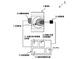
図1を参照しながら、本実施形態に係る光音響測定装置1の構成を説明する。本実施形態に係る光音響測定装置1は、光照射部10、音響波検出部20、信号処理部30を有し
ている。また、信号処理部30は、光量分布計算領域決定部31、規格化光量分布取得部32、被検体情報算出部33を含んでいる。なお、符号2は、被検体である生体の一部であり、符号3は、被検体内にある光吸収体である。
以下、本実施形態に係る光音響測定装置を構成する各手段を説明しながら、測定の方法について概要を説明する。
<System configuration>
The configuration of the
Hereinafter, the outline of the measurement method will be described while describing each means that constitutes the photoacoustic measurement apparatus according to the present embodiment.
<<光照射部10>>
光照射部10は、パルス光を発生させ、被検体に照射する手段であり、光源と、照射光学系(いずれも不図示)からなる。
光源は、大出力を得るためレーザ光源であってもよいが、レーザの代わりに発光ダイオードやフラッシュランプ等を用いることもできる。光源としてレーザを用いる場合、固体レーザ、ガスレーザ、色素レーザ、半導体レーザなど様々なものが使用できる。
出力が強く連続的に波長を変えられる、Nd:YAG励起のTi:saレーザや、アレ
キサンドライトレーザを用いてもよい。また、異なる波長の単波長レーザを複数有していてもよい。
照射のタイミング、波形、強度等は不図示の光源制御部によって制御される。この光源制御部は、光源と一体化されていても良い。
また、パルス光の波長は、被検体を構成する成分のうち特定の成分に吸収される特定の波長であって、被検体内部まで光が伝搬する波長であってもよい。具体的には、被検体が生体である場合、700nm以上1100nm以下であてもよい。
また、光音響波を効果的に発生させるためには、被検体の熱特性に応じて十分短い時間に光を照射させなければならない。被検体が生体である場合、光源から発生するパルス光のパルス幅は10ナノ秒以上、50ナノ秒以下であってもよい。なお、光源から発生するパルス光を以下、照射光と称する。
<<
The
The light source may be a laser light source to obtain a large output, but a light emitting diode or a flash lamp may be used instead of the laser. When a laser is used as a light source, various types such as a solid laser, a gas laser, a dye laser, and a semiconductor laser can be used.
It is also possible to use an Nd: YAG-excited Ti: sa laser or an alexandrite laser, which has a strong output and continuous wavelength change. In addition, a plurality of single wavelength lasers of different wavelengths may be provided.
The irradiation timing, waveform, intensity and the like are controlled by a light source control unit (not shown). The light source control unit may be integrated with the light source.
The wavelength of the pulsed light may be a specific wavelength absorbed by a specific component of the components constituting the subject and may be a wavelength at which the light propagates to the inside of the subject. Specifically, when the subject is a living body, it may be 700 nm or more and 1100 nm or less.
Further, in order to effectively generate a photoacoustic wave, light must be irradiated for a sufficiently short time according to the thermal characteristics of the subject. When the subject is a living body, the pulse width of the pulsed light generated from the light source may be 10 nanoseconds or more and 50 nanoseconds or less. The pulsed light generated from the light source is hereinafter referred to as irradiation light.
照射光学系は、光源から射出されたパルス光を被検体に照射する手段である。照射光学系は、典型的には、光を反射するミラーや光を拡大するレンズ、光を拡散させる拡散板などの光学部材を用いて、照射光を所望の照射光分布形状に加工しながら被検体に導くが、光ファイバなどの導波路などを用いて伝搬させることも可能である。このような光学部品は、光源から発せられた照射光を被検体2に所望の形状で照射できるものであれば、どのようなものを用いてもよい。なお、光はレンズで集光させるより、ある程度の面積に広げる方が被検体への安全性ならびに診断領域を広げられるという観点で好ましい。また、照射光を照射する位置を変えるために、照射光学系に走査機構を設けるようにしてもよい。 The irradiation optical system is means for irradiating the object with the pulsed light emitted from the light source. The irradiation optical system is typically an optical member such as a mirror that reflects light, a lens that expands light, or a diffusion plate that diffuses light, to process the irradiation light into a desired irradiation light distribution shape while being processed. Although it leads to a specimen, it is also possible to propagate using a waveguide such as an optical fiber. As such an optical component, any component may be used as long as it can irradiate the subject 2 with the irradiation light emitted from the light source in a desired shape. In addition, it is preferable to expand light to a certain area rather than condensing the light with a lens in terms of the safety to the subject and the ability to widen the diagnostic region. In addition, a scanning mechanism may be provided in the irradiation optical system in order to change the position at which the irradiation light is irradiated.
<<音響波検出部20>>
音響波検出部20は、被検体内部で発生した音響波を検出し、電気信号(光音響波信号)に変換する手段である。音響波検出部は、単に探触子あるいは音響波検出器、トランスデューサとも呼ばれる。なお、本発明における音響波とは、典型的には超音波であり、音波、超音波、光音響波、光超音波と呼ばれる弾性波を含む。
生体から発生する音響波は、100KHzから100MHzの超音波であるため、音響波検出部20には、上記の周波数帯を検出できる超音波検出器を用いる。具体的には、圧電現象を用いたトランスデューサ、光の共振を用いたトランスデューサ、容量の変化を用いたトランスデューサなどを用いることができる。また、音響波検出部20は、感度が高く、周波数帯域が広いものであってもよい。
また、音響波検出部20は、複数の検出素子が一次元、或いは二次元に配置され、走査機構によって移動可能なものであってもよい。多次元配列素子を用いると、同時に複数の場所で音響波を検出することができるため、測定時間を短縮することができ、被検体の振動などの影響を低減することができる。また、音響レンズでフォーカスされた単一素子を用いてもよい。
<< Acoustic
The acoustic
Since an acoustic wave generated from a living body is an ultrasonic wave of 100 KHz to 100 MHz, the acoustic
In addition, the acoustic
また、音響波検出部20は、得られた電気信号を増幅し、デジタル信号に変換する手段を有している。具体的には、増幅器、A/D変換器、FPGAチップなどを有している。
なお、得られる検出信号が複数である場合は、同時に複数の信号を処理できてもよい。これにより、画像を形成するまでの時間を短縮することができる。
また、被検体に対して同じ位置で検出した音響波信号を積算し、一つの信号にしてもよい。積算の方法は、信号同士を足し合わせるものであってもよいし、平均を取るものであってもよい。また、信号にそれぞれ重みを付けて足しあわせるものであってもよい。
なお、本明細書における「検出信号」とは、音響波検出部から出力されるアナログ信号も、その後A/D変換されたデジタル信号も含む概念である。
Further, the acoustic
In addition, when the detection signal obtained is multiple, several signals may be processable simultaneously. As a result, the time to form an image can be shortened.
Alternatively, the acoustic wave signals detected at the same position with respect to the object may be integrated into one signal. The method of integration may be to add the signals together or to take an average. Also, the signals may be weighted and added together.
In addition, the "detection signal" in this specification is the concept also including the analog signal output from an acoustic wave detection part, and the digital signal by which A / D conversion was carried out after that.
<<信号処理部30>>
信号処理部30は、デジタル変換された信号を処理し、被検体内部の光学特性を表す画像を再構成する手段である。再構成の手法としては、フーリエ変換法、ユニバーサルバックプロジェクション法(UBP法)やフィルタードバックプロジェクション法などがあるが、どのような手法を用いてもよい。生成された画像は、不図示の表示装置によって利用者に提示される。
また、信号処理部30は、光量分布計算領域決定部31と、規格化光量分布取得部32と、被検体情報算出部33とを含んでいる。それぞれの具体的な動作については後述する。
<< Signal processing
The
Further, the
なお、信号処理部30は、CPUと主記憶装置、および補助記憶装置を有する、独立したコンピュータであってもよいし、専用に設計されたハードウェアであってもよい。
信号処理部30には、典型的にはワークステーションなどが用いられ、ソフトウェアによって前述した処理が行われる。例えば、前述した光量分布計算領域決定部31、規格化光量分布取得部32、被検体情報算出部33が、それぞれ対応するソフトウェアによって実行されてもよい。また、それぞれの手段を、別々のハードウェアとしてもよい。この場合、それぞれのハードウェアを総じて信号処理部30と称する。
Note that the
Typically, a workstation or the like is used for the
<被検体の測定方法>
次に、本実施形態に係る光音響測定装置によって、被検体である生体を測定する方法について説明する。
まず、光照射部10から発せられた照射光を被検体に照射する。被検体の内部へ入った照射光は、被検体内(被検体が生体である場合、生体組織内)で拡散および吸収しながら減衰し、照射位置からの距離などに応じた光量分布を形成する。
また、生体内部を伝搬した光のエネルギーの一部が血液などの光吸収体に吸収されると、熱膨張により当該光吸収体から音響波が発生する。例えば、生体内にがんが存在する場合は、がんの新生血管において他の正常部の血液と同様に光が特異的に吸収され、音響波が発生する。
<Method of measuring subject>
Next, a method of measuring a living body as a subject by the photoacoustic measurement apparatus according to the present embodiment will be described.
First, the irradiation light emitted from the
In addition, when a part of the energy of light propagated inside the living body is absorbed by a light absorber such as blood, an acoustic wave is generated from the light absorber due to thermal expansion. For example, when a cancer exists in a living body, light is specifically absorbed in the neovascularization of the cancer as in the blood of other normal parts, and an acoustic wave is generated.
発生した音響波は、被検体内を伝播し、音響波検出部20で検出され、アナログの電気信号に変換される。なお、本実施形態における音響波検出部20は、音響波が発生した位置を特定できるように、フォーカス型の音響レンズを備えた音響波検出素子(不図示)を有している。
また、音響波検出部20は、電気信号を増幅およびデジタル変換し、検出信号を信号処理部30内のメモリ34(記憶部)に格納する。
The generated acoustic wave propagates in the subject, is detected by the acoustic
In addition, the acoustic
次に、信号処理部30に格納された検出信号から、被検体内の光学特性を取得する処理の概要について説明する。
前述したように、被検体内における初期音圧は、光吸収体が有する光吸収係数と、到達した照射光の光量に比例する。すなわち、被検体内の光吸収係数の分布を求めるためには
、当該被検体内における照射光の光量分布を取得する必要がある。
Next, an outline of processing for acquiring an optical characteristic in the subject from the detection signal stored in the
As described above, the initial sound pressure in the subject is proportional to the light absorption coefficient of the light absorber and the light amount of the reached irradiation light. That is, in order to obtain the distribution of the light absorption coefficient in the subject, it is necessary to acquire the light quantity distribution of the irradiation light in the subject.
まず、光量分布計算領域決定部31が、被検体内に照射された照射光の分布を計算するための領域(以下、光量分布計算領域)を決定する。光量分布計算領域は、照射光のプロファイル、被検体の平均光学係数、被検体の形状、想定される光吸収体の吸収係数を用いて決定される。
次に、規格化光量分布取得部32が、照射光のプロファイルと、被検体の平均光学係数を用いて、照射光の光量を規格化した場合における、被検体内部の光量分布(以下、規格化光量分布)を取得する。
最後に、被検体情報算出部33が、実際に被検体に照射された照射光の光強度[J]と、
規格化光量分布と、検出信号を用いて、被検体内の光学特性分布を取得する。取得された光学特性分布は、画像データに変換され、表示装置(不図示)に出力される。
光量分布計算領域決定部31、規格化光量分布取得部32、被検体情報算出部33が行う具体的な処理と、その効果については後述する。
First, the light quantity distribution calculation area determination unit 31 determines an area (hereinafter, light quantity distribution calculation area) for calculating the distribution of the irradiation light irradiated into the object. The light amount distribution calculation area is determined using the profile of the irradiation light, the average optical coefficient of the object, the shape of the object, and the absorption coefficient of the light absorber assumed.
Next, when the normalized light amount distribution acquiring unit 32 normalizes the light amount of the irradiated light using the profile of the irradiated light and the average optical coefficient of the object, the light amount distribution inside the object (hereinafter referred to as normalization) Acquire the light intensity distribution).
Finally, the object information calculation unit 33 calculates the light intensity [J] of the irradiation light actually irradiated to the object.
An optical characteristic distribution in the subject is acquired using the normalized light amount distribution and the detection signal. The acquired optical characteristic distribution is converted into image data and output to a display device (not shown).
Specific processes performed by the light amount distribution calculation area determination unit 31, the normalized light amount distribution acquisition unit 32, and the object information calculation unit 33 and the effects thereof will be described later.
<光学特性分布の取得方法>
次に、照射光を複数回照射した場合において、被検体内の光学特性分布を取得する、従来の方法について説明する。
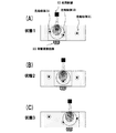
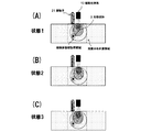
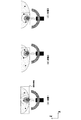
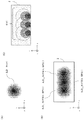
本例では、図2(A)〜図2(C)に示したように、光照射部10および音響波検出部20を、被検体に対して相対的に走査させ、複数の位置で照射光の照射および音響波の取得を行うものとする。なお、ここでは、被検体2、光吸収体3A〜3Cと、光照射部10、音響波検出部20の相対的位置関係を「状態」と称する。具体的には、図2(A)、図2(B)、図2(C)で示した位置関係を、それぞれ状態1、状態2、状態3と称する。以下の説明において、各状態を区別する場合は、状態を表す数字を使用する。
<Method of acquiring optical characteristic distribution>
Next, a conventional method of acquiring the optical characteristic distribution in the subject when the irradiation light is irradiated a plurality of times will be described.
In this example, as shown in FIGS. 2A to 2C, the
ここで、光吸収体3A,3B,3Cの位置を、それぞれrA,rB,rCとし、それぞれの吸収係数を、μt(rA),μt(rB),μt(rC)とおく。
また、状態1,状態2,状態3における実際の光量分布を、それぞれ、Φ1t(r),Φ2t(r),Φ3t(r)とおく。
また、状態1〜状態3における、実際の初期音圧分布をそれぞれP1t(r),P2t(r),P3t(r)とおく。なお、rは被検体内の位置座標である。
また、状態1〜状態3における検出信号を、それぞれS1(r),S2(r),S3(r)とおく。検出信号は、音響波検出部が複数の探触子素子を持つ場合は、複数の検出信号から成る検出信号群となるが、ここでは、検出信号群も含めて、S1(r),S2(r),S3(r)と記載する。
また、それぞれの検出信号から、UBP法などを用いて再構成して得た初期音圧分布を、Pi1(r),Pi2(r),Pi3(r)とし、すべての検出信号を用いて再構成した初期音圧分布を、Pi(r)とおく。
Here, positions of the light absorbers 3A, 3B and 3C are rA, rB and rC, respectively, and absorption coefficients thereof are μt (rA), μt (rB) and μt (rC).
Also, let 分布 1t (r), Φ2t (r), and Φ3t (r) be the actual light quantity distributions in the
Further, actual initial sound pressure distributions in
Further, the detection signals in the
Also, the initial sound pressure distribution obtained by reconstruction from each detection signal using the UBP method or the like is taken as Pi1 (r), Pi2 (r), Pi3 (r), and all the detection signals are used to read again. The configured initial sound pressure distribution is taken as Pi (r).
この時、各光吸収体における初期音圧は、式(1)を用いると、下記の式(2)〜式(4)で表すことができる。なお、ここでは説明を簡単にするため、グルナイゼン係数Γを1、検出信号から得られる初期音圧をR(S(r))とする。すなわち、Pi(r)=R(S(r))である。 At this time, the initial sound pressure in each light absorber can be expressed by the following formulas (2) to (4) using formula (1). Here, in order to simplify the description, it is assumed that the gruneisen coefficient Γ is 1, and the initial sound pressure obtained from the detection signal is R (S (r)). That is, Pi (r) = R (S (r)).
Pi(rA)={P1i(rA)+P2i(rA)+P3i(rA)}/3
={R(S1(rA))+R(S2(rA))+R(S3(rA))}/3
=R(S1(rA),S2(rA),S3(rA)) ・・・式(2)
Pi(rB)={P1i(rB)+P2i(rB)+P3i(rB)}/3
={R(S1(rB))+R(S2(rB))+R(S3(rB))}/3
=R(S1(rB),S2(rB),S3(rB)) ・・・式(3)
Pi(rC)={P1i(rC)+P2i(rC)+P3i(rC)}/3
={R(S1(rC))+R(S2(rC))+R(S3(rC))}/3
=R(S1(rC),S2(rC),S3(rC)) ・・・式(4)
Pi (rA) = {P1i (rA) + P2i (rA) + P3i (rA)} / 3
= {R (S1 (rA)) + R (S2 (rA)) + R (S3 (rA))} / 3
= R (S1 (rA), S2 (rA), S3 (rA)) Formula (2)
Pi (rB) = {P1i (rB) + P2i (rB) + P3i (rB)} / 3
= {R (S1 (rB)) + R (S2 (rB)) + R (S3 (rB))} / 3
= R (S1 (rB), S2 (rB), S3 (rB)) Formula (3)
Pi (rC) = {P1i (rC) + P2i (rC) + P3i (rC)} / 3
= {R (S1 (rC)) + R (S2 (rC)) + R (S3 (rC))} / 3
= R (S1 (rC), S2 (rC), S3 (rC)) Formula (4)
ここで、それぞれの状態で算出された光量分布を、Φ1i(r),Φ2i(r),Φ3i(r)とおいて、式(1)および式(2)を用いて、光吸収体Aの吸収係数μi(rA)を算出すると、式(5)のようになる。
μi(rA)=R(S1(rA),S2(rA),S3(rA))/{(Φ1i(rA)+Φ2i(rA)+Φ3i(rA))/3} ・・・式(5)
Here, assuming that the light amount distributions calculated in the respective states are 11i (r), Φ2i (r), and Φ3i (r), absorption of the light absorber A is performed using the equations (1) and (2). When the coefficient μi (rA) is calculated, it becomes as shown in Expression (5).
μi (rA) = R (S1 (rA), S2 (rA), S3 (rA)) / {(. PHI.1i (rA) +. PHI.2i (rA) +. PHI.3i (rA)) / 3} (5)
また、式(1)および式(3)を用いて、光吸収体Bの吸収係数μi(rB)を算出すると、式(6)のようになる。
μi(rB)=P(rB)/{(Φ1(rB)+Φ2(rB)+Φ3(rB))/3}=R(S1(rB),S2(rB),S3(rB))/{(Φ1i(rB)+Φ2i(rB)+Φ3i(rB))/3} ・・・式(6)
In addition, when the absorption coefficient μi (rB) of the light absorber B is calculated using Expression (1) and Expression (3), Expression (6) is obtained.
μi (rB) = P (rB) / {(Φ1 (rB) + Φ2 (rB) + Φ3 (rB)) / 3} = R (S1 (rB), S2 (rB), S3 (rB)) / {(Φ1i (RB) + Φ2i (rB) + Φ3i (rB)) / 3} (6)
また、式(1)および式(4)を用いて、光吸収体Cの吸収係数μi(rC)を算出すると、式(7)のようになる。
μi(rC)=3・P(rC)/{Φ1(rC)+Φ2(rC)+Φ3(rC)}=3・R(S1(rC),S2(rC),S3(rC))/{(Φ1i(rC)+Φ2i(rC)+Φ3i(rC))/3} ・・・式(7)
ここでは、複数の照射をした際の初期音圧を算出する手法として、式(2)(3)(4)のように、各照射において算出した初期音圧を加算平均する手法を用いた。そのため、吸収係数を算出する式(5)(6)(7)における分母(光量)を照射回数で割っている。しかし、複数の照射をした際の初期音圧を算出する手法として、以下の式を用いてもよい。
P‘i(rA)={P1i(rA)+P2i(rA)+P3i(rA)}
={R(S1(rA))+R(S2(rA))+R(S3(rA)))}
=R‘(S1(rA),S2(rA),S3(rA))
この場合、以下の式を用いて吸収係数を算出することができる。
μi(rA)=R‘(S1(rA),S2(rA),S3(rA))/{(Φ1i(rA)+Φ2i(rA)+Φ3i(rA))}
なお、本明細書に記載の全ての実施形態では、どちらの手法をも採用することができるが、簡単のため、ここでは積算平均の手法を用いて説明する。
In addition, when the absorption coefficient μi (rC) of the light absorber C is calculated using Expression (1) and Expression (4), Expression (7) is obtained.
μi (rC) = 3 · P (rC) / {Φ1 (rC) + Φ2 (rC) + Φ3 (rC)} = 3 · R (S1 (rC), S2 (rC), S3 (rC)) / {(Φ1i (RC) + Φ2i (rC) + Φ3i (rC)) / 3} formula (7)
Here, as a method of calculating the initial sound pressure at the time of performing a plurality of irradiations, a method of averaging the initial sound pressures calculated in each of the irradiations is used as shown in equations (2), (3) and (4). Therefore, the denominator (light quantity) in the equations (5) (6) (7) for calculating the absorption coefficient is divided by the number of times of irradiation. However, the following equation may be used as a method of calculating the initial sound pressure when a plurality of irradiations are performed.
P'i (rA) = {P1i (rA) + P2i (rA) + P3i (rA)}
= {R (S1 (rA)) + R (S2 (rA)) + R (S3 (rA)))}
= R '(S1 (rA), S2 (rA), S3 (rA))
In this case, the absorption coefficient can be calculated using the following equation.
μi (rA) = R '(S1 (rA), S2 (rA), S3 (rA)) / {(. PHI.1i (rA) +. PHI.2i (rA) +. PHI.3i (rA))}
In all the embodiments described in this specification, either method can be adopted, but for the sake of simplicity, the method will be described using the method of integration averaging.
光量分布Φi(r)は、予め、被検体2の表面における照射光分布Oを測定し、照射光分布O(r)をソースとして、拡散方程式や輸送方程式を、有限要素法や有限体積法、差分法などを使って計算することで求めることができる。
また、光量分布Φi(r)は、拡散光伝搬の解析解や、光伝搬を、モンテカルロ法を用いて解くことで求めることもできる。光量を計算できるものであれば、どのようなものを用いてもよい。そのため、光照射部10は、最終的に算出する被検体情報の許容誤差を逸脱しない程度に、被検体2の表面位置における照射光分布O(r)が同じになるようにパルス光を照射してもよい。
The light quantity distribution ii (r) is obtained by measuring the irradiation light distribution O on the surface of the subject 2 in advance, using the irradiation light distribution O (r) as the source, the diffusion equation and the transport equation, the finite element method, the finite volume method, It can be obtained by calculation using a difference method or the like.
The light quantity distribution 分布 i (r) can also be obtained by solving an analytical solution of diffused light propagation or light propagation using the Monte Carlo method. Any kind of light quantity can be used as long as it can calculate the light quantity. Therefore, the
次に、実際の値を当てはめて説明する。ここでは、被検体が、縦50mm、横120mm、奥行き120mmの直方体であるものと仮定して説明を行う。また、被検体の平均吸収係数μaMを0.005/mm、平均等価散乱係数μs’Mを0.85/mmとおく。平均吸収係数は、被検体2の全領域で均一とした吸収係数であり、平均等価散乱係数は、被検体2の全領域で均一とした等価散乱係数である。 Next, an actual value is applied and demonstrated. Here, the description will be made on the assumption that the subject is a rectangular parallelepiped 50 mm long, 120 mm wide, and 120 mm deep. Further, the average absorption coefficient μaM of the subject is set to 0.005 / mm, and the average equivalent scattering coefficient μs'M is set to 0.85 / mm. The average absorption coefficient is an absorption coefficient that is uniform over the entire region of the subject 2, and the average equivalent scattering coefficient is an equivalent scattering coefficient that is uniform over the entire region of the subject 2.
また、照射光は、被検体2の表面に、直径30mmの円形状で均一に照射されるものとし、その光強度は、状態1において100mJ、状態2において125mJ、状態3において80mJであるものとする。また、光吸収体A、光吸収体B、光吸収体Cは血管であるものとし、吸収係数μを150/mとする。
Further, the irradiation light is uniformly irradiated on the surface of the subject 2 in a circular shape with a diameter of 30 mm, and the light intensity is 100 mJ in
以上の値を用いた場合の、各吸収体位置における実際の光量は、それぞれ以下のようになる。
Φ1t(rA)=50J/m2,Φ1t(rB)=3J/m2,Φ1t(rC)=0.003J/m2
Φ2t(rA)=0.02J/m2,Φ2t(rB)=500J/m2,Φ2t(rC)=0.03J/m2
Φ3t(rA)=0.0007J/m2,Φ3t(rB)=4J/m2,Φ3t(rC)=20J/m2
The actual amount of light at each absorber position when using the above values is as follows.
1 1 t (rA) = 50 J / m 2 , 1 1 t (r B) = 3 J / m 2 , Φ 1 t (r C) = 0.003 J / m 2
Φ 2 t (rA) = 0.02 J / m 2 , Φ 2 t (r B) = 500 J / m 2 , Φ 2 t (r C) = 0.03 J / m 2
Φ3t (rA) = 0.0007J / m 2, Φ3t (rB) = 4J / m 2, Φ3t (rC) = 20J / m 2
また、各吸収体位置における実際の初期音圧は、それぞれ以下のようになる。
P1t(rA)=7500Pa,P1t(rB)=450Pa,P1t(rC)=0.45Pa
P2t(rA)=3Pa,P2t(rB)=75000Pa,P2t(rC)=4.5Pa
P3t(rA)=0.105Pa,P3t(rB)=600Pa,P3t(rC)=3000Pa
Also, the actual initial sound pressure at each absorber position is as follows.
P1t (rA) = 7500 Pa, P1t (rB) = 450 Pa, P1t (rC) = 0.45 Pa
P2t (rA) = 3 Pa, P2t (rB) = 75000 Pa, P2t (rC) = 4.5 Pa
P3t (rA) = 0.105Pa, P3t (rB) = 600Pa, P3t (rC) = 3000Pa
以上に説明した実際の光量分布と、初期音圧分布を演算によって求める例を挙げる。光量分布は、被検体の平均吸収係数、平均散乱係数、被検体表面の照射光分布O、被検体の形状に基づいて、光の伝搬を計算することで得ることができる。また、初期音圧分布は、検出信号を再構成することで得ることができる。 An example will be described in which the actual light intensity distribution described above and the initial sound pressure distribution are obtained by calculation. The light quantity distribution can be obtained by calculating the propagation of light based on the average absorption coefficient of the object, the average scattering coefficient, the irradiation light distribution O of the object surface, and the shape of the object. Also, the initial sound pressure distribution can be obtained by reconstructing the detection signal.
ここでは、光量分布および初期音圧分布を正確に算出できるものとし、それぞれの値を以下のようにおく。
Φ1i(rA)=50J/m2,Φ1i(rB)=1.5J/m2,Φ1i(rC)=0.003J/m2
Φ2i(rA)=0.02J/m2,Φ2i(rB)=500J/m2,Φ2i(rC)=0.03J/m2
Φ3i(rA)=0.0007J/m2,Φ3i(rB)=2J/m2,Φ3i(rC)=20J/m2
Here, it is assumed that the light amount distribution and the initial sound pressure distribution can be accurately calculated, and the respective values are set as follows.
Φ1i (rA) = 50J / m 2, Φ1i (rB) = 1.5J / m 2, Φ1i (rC) = 0.003J / m 2
Φ2i (rA) = 0.02J / m 2, Φ2i (rB) = 500J / m 2, Φ2i (rC) = 0.03J / m 2
Φ3i (rA) = 0.0007J / m 2, Φ3i (rB) = 2J / m 2, Φ3i (rC) = 20J / m 2
P1i(rA)=7500Pa,P1i(rB)=225Pa,P1i(rC)=0.45Pa
P2i(rA)=3Pa,P2i(rB)=75000Pa,P2i(rC)=3Pa
P3i(rA)=0.105Pa,P3i(rB)=300Pa,P3i(rC)=3000Pa
P1i (rA) = 7500 Pa, P1i (rB) = 225 Pa, P1i (rC) = 0.45 Pa
P2i (rA) = 3 Pa, P2i (rB) = 75000 Pa, P2i (rC) = 3 Pa
P3i (rA) = 0.105Pa, P3i (rB) = 300Pa, P3i (rC) = 3000Pa
次に、各光吸収体の吸収係数を算出する。式(5),式(6),式(7)に対して、前述した値を適用すると、吸収係数は以下のようになる。
μ(rA)={(7500+3+0.105)/3}/{(50+0.02+0.007)/3}=150/m
μ(rB)={(225+75000+300)/3}/{(1.5+500+2)/3}=150/m
μ(rC)={(0.45+4.5+3000)/3}/{(0.003+0.03+20)/3}=150/m
Next, the absorption coefficient of each light absorber is calculated. Applying the above-described values to the equations (5), (6), and (7), the absorption coefficient is as follows.
μ (rA) = {(7500 + 3 + 0.105) / 3} / {(50 + 0.02 + 0.007) / 3} = 150 / m
μ (rB) = {(225 + 75000 + 300) / 3} / {(1.5 + 500 + 2) / 3} = 150 / m
μ (rC) = {(0.45 + 4.5 + 3000) / 3} / {(0.003 + 0.03 + 20) / 3} = 150 / m
以上に説明した方法によって、被検体内における吸収係数(真値:150/m)を算出することができる。 The absorption coefficient (true value: 150 / m) in the subject can be calculated by the method described above.
しかし、前述した方法では、各状態において、被検体2の一部のみに照射光が照射されている場合であっても、全領域(120mm×120mm×50mm)に対する光量分布を算出する必要がある。例えば、解像度を1mm×1mm×1mmのボクセルとすると、120×120×50=720,000個のボクセルについて演算を行う必要があり、膨大な計算コストがかかってしまう。つまり、第一の問題として、不必要な領域に対して演算が行われてしまうという問題がある。 However, in the method described above, it is necessary to calculate the light quantity distribution for the entire area (120 mm × 120 mm × 50 mm) even when only a part of the subject 2 is irradiated with the irradiation light in each state. . For example, assuming that the resolution is 1 mm × 1 mm × 1 mm voxels, it is necessary to perform calculations on 120 × 120 × 50 = 720,000 voxels, which results in a huge computational cost. That is, the first problem is that the operation is performed on an unnecessary area.
また、前述したように、光量分布を、拡散方程式や輸送方程式などによって求めなければならないため、多大な計算コストがかかる。また、パルス光の照射回数が多くなると、比例して演算量も増大する。つまり、第二の問題として、光量分布を求めるための演算量がそもそも多いという問題がある。 In addition, as described above, since the light amount distribution has to be determined by the diffusion equation, the transport equation, etc., a great computational cost is required. In addition, as the number of times of pulse light irradiation increases, the amount of calculation also increases in proportion. That is, there is a second problem that the amount of calculation for obtaining the light amount distribution is large in the first place.
そこで、本実施形態では、下記の(1)と(2)で説明する構成を採用することによって、前述した二つの問題を解決する。 So, in this embodiment, the two problems mentioned above are solved by employ | adopting the structure demonstrated by the following (1) and (2).
(1)光量分布計算領域を限定することによる演算量の削減
本実施形態では、到達する照射光が十分弱く、吸収係数の算出に大きく影響しない領域を省いた領域、すなわち、吸収係数の算出に大きく寄与する領域(光量分布計算領域)を設定し、光量分布を計算する。光量分布計算領域は、光量分布計算領域決定部31によって決定される。
光量分布計算領域は、例えば、照射光が被検体に入射する際の表面における光量分布、被検体の形状、平均吸収係数や平均散乱係数から想定される光量分布などに基づいて決定することができる。また、探触子の指向性や感度などを用いた空間感度分布、または、予め実測された空間感度分布に基づいて決定してもよい。また、観察を所望する光吸収体の吸収係数と、その形状に基づいて決定してもよい。
(1) Reduction of operation amount by limiting the light amount distribution calculation area In the present embodiment, the reaching irradiation light is sufficiently weak, and an area where the area not largely affecting the calculation of the absorption coefficient is omitted, ie, the calculation of the absorption coefficient An area (light quantity distribution calculation area) that largely contributes is set, and the light quantity distribution is calculated. The light quantity distribution calculation area is determined by the light quantity distribution calculation area determination unit 31.
The light amount distribution calculation area can be determined based on, for example, the light amount distribution on the surface when the irradiation light enters the object, the shape of the object, the light amount distribution assumed from the average absorption coefficient and the average scattering coefficient, etc. . Also, it may be determined based on the spatial sensitivity distribution using the directivity or sensitivity of the probe, or the spatial sensitivity distribution measured in advance. Also, it may be determined based on the absorption coefficient of the light absorber desired to be observed and the shape thereof.
例えば、観察を所望する光吸収体が、直径500μmの血管であり、波長797nmにおける吸収係数μtargetが0.2/mm相当であるものとする。また、照射光の照射密度Φ0を、200J/m2とする。また、当該血管から、中心周波数3MHzの音響波が発
生した場合の、音響波検出部の1素子のNEP(Noise Equivalent Pressure)を、1P
aとする。ここで、音響波検出部からの距離rovが35mmであり、照射光が入射する表面からの距離rvdが30mmであるボクセルHについて考えると、式(8)より、Φ(rov)=0.6J/m2となる。
Φ(rov)=Φ0exp(−ueff・rov)/rov ・・・式(8)
For example, the light absorber desired to be observed is a blood vessel having a diameter of 500 μm, and the absorption coefficient μ target at a wavelength of 797 nm is equivalent to 0.2 / mm. Further, the irradiation density 00 of the irradiation light is set to 200 J / m 2 . In addition, when an acoustic wave with a center frequency of 3 MHz is generated from the blood vessel, NEP (Noise Equivalent Pressure) of one element of the acoustic wave detection unit is 1P.
a. Here, considering a voxel H in which the distance rov from the acoustic wave detection unit is 35 mm and the distance rvd from the surface on which the irradiation light is incident is 30 mm, 式 (rov) = 0.6 J from the equation (8) / M 2
((Rov) = 0 0 exp (-u eff · rov) / rov · · · Equation (8)
Φ(rov)は、照射光の入射位置から対象ボクセルまでの距離rovにおける光量であり、Φ0は照射光の入射面(皮膚)における光量、ueffは光減衰係数である。被検体
が人の乳房である場合、ueffは0.08/mm程度である。吸収係数が0.2/mmで
ある光吸収体に、0.6J/m2の光量が届いた場合に発生する音響波の初期音圧は、1
20Paとなる。このボクセルから音響波検出部までは、rvd=35mmの距離がある。一方、音響波は、1/√rvdの減衰率で減衰するため、音響波検出部には20.28Paの音圧が届く。
Φ (rov) is the amount of light at the distance rov from the incident position of the irradiation light to the target voxel, Φ 0 is the amount of light at the incident surface (skin) of the irradiation light, and u eff is the light attenuation coefficient. When the subject is a human breast, u eff is about 0.08 / mm. The initial sound pressure of the acoustic wave generated when the light quantity of 0.6 J / m 2 reaches the light absorber having an absorption coefficient of 0.2 / mm is 1
It will be 20Pa. There is a distance of rvd = 35 mm from this voxel to the acoustic wave detection unit. On the other hand, since the acoustic wave is attenuated at an attenuation rate of 1 / √vd, a sound pressure of 20.28 Pa reaches the acoustic wave detection unit.
ここで、対象のボクセルが、音響波検出部の正面方向に対して30°の位置にあり、ボクセルHから到来する音響波が、探触子の正面に対して30°傾いて入射するものとする。周波数3MHzにおける、指向角30°での音響波検出部の感度は、正面の1/20で
あるため、20.28Paの音圧を持つ音響波は、約1Paの信号として検出される。一方、NEPは1Paであるため、SN比(Signal−Noise比)は1となる。また、探触子が10個の素子を持っており、ノイズがホワイトノイズである場合、SN比は1/(1/√10)=3.16となる。
このように、式(9)より、あるボクセルにおけるSN比が簡易的に求まる。
SN比=(μtarget・Φ0・exp(−ueff・rov)/rov)/√rvd・AS
(θ)/(NEP(f)/√N) ・・・式(9)
ここで、AS(θ)は、音響波検出部の正面方向に対して、角度θで音響波が入射した
場合の、正面に対する検出感度である。また、Nは探触子の数または測定回数である。また、NEP(f)は、中心周波数fにおけるNEPである。
Here, the voxel of interest is at a position of 30 ° with respect to the front direction of the acoustic wave detection unit, and the acoustic wave coming from the voxel H is incident at an inclination of 30 ° with respect to the front of the probe. Do. Since the sensitivity of the acoustic wave detection unit at a directivity angle of 30 ° at a frequency of 3 MHz is 1/20 of the front, an acoustic wave having a sound pressure of 20.28 Pa is detected as a signal of about 1 Pa. On the other hand, since NEP is 1 Pa, the SN ratio (Signal-Noise ratio) is 1. When the probe has 10 elements and the noise is white noise, the SN ratio is 1 / (1 / √10) = 3.16.
As described above, the SN ratio at a certain voxel can be easily obtained from equation (9).
SN ratio = (μ target · 0 0 · exp (-u eff · rov) / rov) / rv rvd · AS
(Θ) / (NEP (f) / √N) (9)
Here, AS (θ) is the detection sensitivity to the front when the acoustic wave is incident at an angle θ with respect to the front direction of the acoustic wave detection unit. Also, N is the number of probes or the number of measurements. Also, NEP (f) is the NEP at the center frequency f.
観察を所望する光吸収体を、直径500μm、吸収係数が0.2/mmの血管とした場合に、3MHzにおけるNEPが1Pa、指向感度がcosθである探触子を利用し、SN比=3を得たいとする。この場合、式(9)より、光量分布計算領域を、50mm×50mm×50mm程度の大きさとすればよいことがわかる。
なお、光量分布計算領域以外の領域については、到達するパルス光の光量は0であるものとして扱う。
When a light absorber desired to be observed is a blood vessel having a diameter of 500 μm and an absorption coefficient of 0.2 / mm, an SN ratio of 3 using a probe with an NEP at 3 MHz of 1 Pa and a pointing sensitivity of cos θ Suppose you want to get In this case, it can be understood from Equation (9) that the light amount distribution calculation area may be set to a size of about 50 mm × 50 mm × 50 mm.
In the region other than the light amount distribution calculation region, the light amount of the arriving pulse light is treated as being zero.
図2中の点線が、光量分布計算領域決定部31が決定した光量分布計算領域である。ここで、このように光量分布計算領域を設定した場合における、演算結果の誤差について説明する。図2の光吸収体A〜Cについて算出された光量は、それぞれ以下のようになる。なお、初期音圧は同一であるものとする。
Φ1i(rA)=50J/m2,Φ1i(rB)=3J/m2,Φ1i(rC)=0J/m2
Φ2i(rA)=0J/m2,Φ2i(rB)=500J/m2,Φ2i(rC)=0J/m2
Φ3i(rA)=0J/m2,Φ3i(rB)=4J/m2,Φ3i(rC)=20J/m2
The dotted line in FIG. 2 is the light quantity distribution calculation area determined by the light quantity distribution calculation area determination unit 31. Here, the error of the calculation result when the light amount distribution calculation area is set as described above will be described. The amounts of light calculated for the light absorbers A to C in FIG. 2 are as follows. The initial sound pressure is assumed to be the same.
11i (rA) = 50 J / m 2 , 11i (rB) = 3 J / m 2 , 11i (rC) = 0 J / m 2
22i (rA) = 0 J / m 2 , 22i (rB) = 500 J / m 2 , Φ2 i (rC) = 0 J / m 2
33i (rA) = 0 J / m 2 , 33 i (rB) = 4 J / m 2 , 33 i (rC) = 20 J / m 2
次に、各光吸収体の吸収係数を算出する。式(5),式(6),式(7)に対して、前述した値を適用すると、吸収係数は以下のようになる。
μi(rA)={(7500+3+0.105)/3}/{(50+0+0)/3}=150.0621/m
μi(rB)={(225+75000+300)/3}/{(0+500+0)/3}=151.05/m
μi(rC)={(0.45+4.5+3000)/3}/{(0+0+20)/3}=150.02/m
すなわち、真値150/mに対して、1%以下の誤差で吸収係数を算出することができることがわかる。
Next, the absorption coefficient of each light absorber is calculated. Applying the above-described values to the equations (5), (6), and (7), the absorption coefficient is as follows.
μi (rA) = {(7500 + 3 + 0.105) / 3} / {(50 + 0 + 0) / 3} = 150.0621 / m
μi (rB) = {(225 + 75000 + 300) / 3} / {(0 + 500 + 0) / 3} = 151.05 / m
μi (rC) = {(0.45 + 4.5 + 3000) / 3} / {(0 + 0 + 20) / 3} = 150.02 / m
That is, it is understood that the absorption coefficient can be calculated with an error of 1% or less with respect to the true value 150 / m.
さらに、初期音圧分布の算出方法を工夫し、光量分布計算領域外の初期音圧を0として、各光吸収体の吸収係数を算出すると、以下のようになる。
μi(rA)={(7500+0+0)/3}/{(50+0+0)/3}=150/m
μi(rB)={(0+75000+0)/3}/{(0+500+0)/3}=150/m
μi(rC)={(0+0+3000)/3}/{(0+0+20)/3}=150/m
Furthermore, when the calculation method of the initial sound pressure distribution is devised and the initial sound pressure outside the light amount distribution calculation area is set to 0, the absorption coefficient of each light absorber is calculated as follows.
μi (rA) = {(7500 + 0 + 0) / 3} / {(50 + 0 + 0) / 3} = 150 / m
μi (rB) = {(0 + 75000 + 0) / 3} / {(0 + 500 + 0) / 3} = 150 / m
μi (rC) = {(0 + 0 + 3000) / 3} / {(0 + 0 + 20) / 3} = 150 / m
以上に説明したように、本実施形態では、光量分布計算領域を設定することにより、7
20,000個ある演算対象ボクセルを、50×50×50=125,000個に減らすことができる。すなわち、計算速度を、(720000/125000)2≒33倍に高
速化することができる。
As described above, in the present embodiment, by setting the light amount distribution calculation area, 7
The 20,000 operation target voxels can be reduced to 50 × 50 × 50 = 125,000. That is, the calculation speed can be increased to (720000/125000) 2 33 33 times.
なお、観察を所望する光吸収体の吸収係数や形状、探触子のNEPや指向性は、装置のオペレータが入力部から入力してもよいし、予め装置に記憶されていてもよい。また、本例では、被検体内の光量分布と探触子の感度から、光量分布算出領域を決定したが、光量分布のみを用いてもよいし、探触子の感度のみを用いてもよい。 The absorption coefficient and shape of the light absorber desired for observation, the NEP and the directivity of the probe may be input from the input unit of the apparatus operator, or may be stored in the apparatus in advance. In this example, the light amount distribution calculation area is determined from the light amount distribution in the object and the sensitivity of the probe, but only the light amount distribution may be used or only the sensitivity of the probe may be used. .
(2)規格化光量分布を用いることによる演算量の削減
一方、光量分布は、前述したように拡散方程式や輸送方程式などによって求めなければならないため、多大な計算コストがかかる。また、パルス光の照射回数が多くなると、比例して演算量も増大する。そこで、本実施形態では、規格化された光量分布を事前に用意しておき、パルス光の出力を乗算することで、各照射における光量分布を算出する。
(2) Reduction of Calculation Amount by Using Normalized Light Amount Distribution On the other hand, since the light amount distribution has to be determined by the diffusion equation, the transport equation, etc. as described above, it requires a great amount of calculation cost. In addition, as the number of times of pulse light irradiation increases, the amount of calculation also increases in proportion. Therefore, in the present embodiment, the normalized light amount distribution is prepared in advance, and the light amount distribution in each irradiation is calculated by multiplying the output of pulsed light.
具体的には、まず、照射光のプロファイルに基づいて、照射光分布Oの総光強度を1mJに規格化した照射光分布O’(以降、規格化照射光分布)を算出する。そして、規格化照射光分布と被検体の光学係数(例えば、平均吸収係数と平均散乱係数)とに基づいて、光量分布計算領域における、規格化された光量分布(以下、規格化光量分布)ΦN(rr)を算出する。ここでrrは、規格化光量分布に対応する座標系における、光の照射領域に対する相対座標である。
算出は、規格化光量分布取得部32によって、測定開始時(例えば、最初のパルス光照射時)に行われ、算出された規格化光量分布が測定中において繰り返し利用される。規格化光量分布は、使用する照射光と、測定対象の被検体が同じである限り、同じデータとなる。すなわち、規格化光量分布を用いることで、パルス光を照射するごとに一から光量分布を演算せずとも、被検体内の光量分布を得ることができる。
Specifically, first, based on the profile of the irradiation light, the irradiation light distribution O ′ (hereinafter, normalized irradiation light distribution) in which the total light intensity of the irradiation light distribution O is normalized to 1 mJ is calculated. Then, based on the normalized irradiation light distribution and the optical coefficient of the object (for example, the average absorption coefficient and the average scattering coefficient), normalized light amount distribution (hereinafter, normalized light amount distribution) N N in the light amount distribution calculation area Calculate (rr). Here, rr is a relative coordinate with respect to the irradiation area of light in the coordinate system corresponding to the normalized light quantity distribution.
The calculation is performed by the normalized light amount distribution acquisition unit 32 at the start of measurement (for example, at the time of first pulse light irradiation), and the calculated normalized light amount distribution is repeatedly used during measurement. The normalized light amount distribution is the same data as long as the irradiation light used and the object to be measured are the same. That is, by using the normalized light amount distribution, it is possible to obtain the light amount distribution in the subject without calculating the light amount distribution from scratch each time the pulsed light is irradiated.
ここで、状態1〜3における、光吸収体A〜Cの位置に対応する規格化光量は、以下のように表すことができる。
Φ1N(rA)=ΦN(FS(rA,SP1))=0.5J/m2,Φ1N(rB)=ΦN(FS(rB,SP1))=0.03J/m2,Φ1N(rC)=ΦN(FS(rC,SP1))=0J/m2
Φ2N(rA)=ΦN(FS(rA,SP2))=0J/m2,Φ2N(rB)=ΦN(FS(rB,SP2))=5J/m2,Φ2N(rC)=ΦN(FS(rC,SP2))=0J/m2
Φ3N(rA)=ΦN(FS(rA,SP3))=0J/m2,Φ3N(rB)=ΦN(FS(rB,SP3))=0.05J/m2,Φ3N(rC)=ΦN(FS(rC,SP3))=0.25J/m2
となる。ここで、ΦNは規格化光量分布であり、S1、S2、S3は、照射領域の位置座標である。FSは、吸収体の絶対座標rA、rB、rCと、光の照射領域の位置座標SP1、SP2、SP3を、規格化光量分布の座標系に変換する関数である。すなわち、関数FSは、規格化光量分布に対応する座標系rrにおける規格化光量値を、照射領域に対応する座標系における規格化光量値に変換するための関数である。
Here, the normalized light amount corresponding to the positions of the light absorbers A to C in the
1 1 N (r A) = N N (FS (r A, SP 1)) = 0.5 J / m 2 , 1 1 N (r B) = N N (FS (r B, SP 1)) = 0.03 J / m 2 , Φ 1 N (r C) = N N (FS (rC, SP1)) = 0 J / m 2
Φ2N (rA) = ΦN (FS (rA, SP2)) = 0J / m 2, Φ2N (rB) = ΦN (FS (rB, SP2)) = 5J / m 2, Φ2N (rC) = ΦN (FS (rC , SP2)) = 0 J / m 2
33N (rA) = ΦN (FS (rA, SP3)) = 0 J / m 2 , 33N (rB) = ΦN (FS (rB, SP3)) = 0.05 J / m 2 , 33 N (rC) = ΦN (FS) (RC, SP3)) = 0.25 J / m 2
It becomes. Here, ΦN is the normalized light amount distribution, and S1, S2, and S3 are position coordinates of the irradiation area. FS is a function that converts the absolute coordinates rA, rB, rC of the absorber and the position coordinates SP1, SP2, SP3 of the light irradiation area into the coordinate system of the normalized light amount distribution. That is, the function FS is a function for converting the normalized light amount value in the coordinate system rr corresponding to the normalized light amount distribution into the normalized light amount value in the coordinate system corresponding to the irradiation area.
ここで得られた規格化光量に、実際の照射光の総光強度を乗算することで、被検体内における光量分布を得ることができる。本実施形態では、被検体情報算出部33が、規格化光量分布ΦN(rr)に照射光の光強度Eを乗算し、得られた光量分布と、検出信号を用いて吸収係数を算出する。なお、照射光の光強度Eは、光照射部10から出射したパルス光の光強度を測定することで取得してもよいし、光源から取得した情報に基づいて推定してもよい。
各状態における照射光の光強度をE1,E2,E3とすると、吸収係数は、以下のように算出することができる。
By multiplying the normalized light amount obtained here by the total light intensity of the actual irradiation light, the light amount distribution in the subject can be obtained. In the present embodiment, the object information calculation unit 33 multiplies the normalized light amount distribution NN (rr) by the light intensity E of the irradiation light, and calculates the absorption coefficient using the obtained light amount distribution and the detection signal. The light intensity E of the irradiation light may be obtained by measuring the light intensity of the pulse light emitted from the
Assuming that the light intensities of the irradiation light in each state are E1, E2, and E3, the absorption coefficient can be calculated as follows.
μi(rA)=R(S1(rA),S2(rA),S3(rA))/{(Φ1N(rA)×E1+Φ2N(rA)×E2+Φ3N(rA)×E3)/3} ・・・式(10)
μi(rB)=R(S1(rB),S2(rB),S3(rB))/{(Φ1N(rB)×E1+Φ2i(rB)×E2+Φ3i(rB)×E3)/3} ・・・式(11)
μi(rC)=R(S1(rC),S2(rC),S3(rC))/{(Φ1N(rC)×E1+Φ2i(rC)×E2+Φ3i(rC)×E3)/3} ・・・式(12)
μi (rA) = R (S1 (rA), S2 (rA), S3 (rA)) / {(. PHI.1N (rA) .times.E1 + .PHI.2N (rA) .times.E2 + .PHI.3N (rA) .times.E3) / 3}. 10)
μi (rB) = R (S1 (rB), S2 (rB), S3 (rB)) / {(. PHI.1N (rB) .times.E1 + .PHI.2i (rB) .times.E2 + .PHI.3i (rB) .times.E3) / 3}. 11)
μi (rC) = R (S1 (rC), S2 (rC), S3 (rC)) / {(Φ1N (rC) × E1 + Φ2i (rC) × E2 + Φ3i (rC) × E3) / 3} 12)
なお、式(10)、式(11)、式(12)では、照射光の光強度Eを規格化光量に乗算したが、式(13)、式(14)、式(15)のように、検出信号から照射光の光強度Eを除算しても、演算後に同じ結果が得られる。
μi(rA)=R(S1(rA)/E1,S2(rA)/E2,S3(rA)/E3)/{(Φ1N(rA)+Φ2N(rA)+Φ3N(rA))/3} ・・・式(13)
μi(rB)=R(S1(rB)/E1,S2(rB)/E2,S3(rB)/E3)/{(Φ1N(rB)+Φ2i(rB)+Φ3i(rB))/3} ・・・式(14)
μi(rC)=R(S1(rC)/E1,S2(rC)/E2,S3(rC)/E3)/{(Φ1N(rC)+Φ2i(rC)+Φ3i(rC))/3} ・・・式(15)
In the equations (10), (11) and (12), the light intensity E of the irradiation light is multiplied by the normalized light amount, but as in the equations (13), (14) and (15) By dividing the light intensity E of the irradiation light from the detection signal, the same result can be obtained after the calculation.
μi (rA) = R (S1 (rA) / E1, S2 (rA) / E2, S3 (rA) / E3) / {(Φ1N (rA) +) 2N (rA) + Φ3N (rA)) / 3} Formula (13)
μi (rB) = R (S1 (rB) / E1, S2 (rB) / E2, S3 (rB) / E3) / {(. PHI.1N (rB) +. PHI.2i (rB) +. PHI.3i (rB)) / 3}. Formula (14)
μi (rC) = R (S1 (rC) / E1, S2 (rC) / E2, S3 (rC) / E3) / {(Φ1N (rC) + Φ2i (rC) + Φ3i (rC)) / 3} Formula (15)
次に、前述した値を当てはめて、各光吸収体の吸収係数を算出する。式(10)、式(11)、式(12)に対して、前述した値を適用すると、吸収係数は以下のようになる。
μi(rA)={(7500+3+0.105)/3}/{(0.5×100+0×125+0×80)/3}=150.0621/m
μi(rB)={(225+75000+300)/3}/{(0×100+4×125+0×80)/3}=151.05/m
μi(rC)={(0.45+4.5+3000)/3}/{(0×100+0×125+0.25×80)/3}=150.02/m
すなわち、真値150/mに対して、1%以下の誤差で算出することが可能であることがわかる。
Next, the absorption coefficient of each light absorber is calculated by applying the values described above. When the above-mentioned values are applied to the equation (10), the equation (11), and the equation (12), the absorption coefficient is as follows.
μi (rA) = {(7500 + 3 + 0.105) / 3} / {(0.5 × 100 + 0 × 125 + 0 × 80) / 3} = 150.0621 / m
μi (rB) = {(225 + 75000 + 300) / 3} / {(0 × 100 + 4 × 125 + 0 × 80) / 3} = 151.05 / m
μi (rC) = {(0.45 + 4.5 + 3000) / 3} / {(0 × 100 + 0 × 125 + 0.25 × 80) / 3} = 150.02 / m
That is, it is understood that it is possible to calculate with an error of 1% or less with respect to the true value 150 / m.
さらに、初期音圧分布の算出方法を工夫し、光量分布計算領域外の初期音圧を0として、各光吸収体の吸収係数を算出すると、以下のようになる。
μi(rA)={(7500+0+0)/3}/{(0.5×100+0×125+0×80)/3}=150/m
μi(rB)={(0+75000+0)/3}/{0×100+4×125+0×80)/3}=150/m
μi(rC)={(0+0+3000)/3}/{(0×100+0×125+0.25×80)/3}=150/m
Furthermore, when the calculation method of the initial sound pressure distribution is devised and the initial sound pressure outside the light amount distribution calculation area is set to 0, the absorption coefficient of each light absorber is calculated as follows.
μi (rA) = {(7500 + 0 + 0) / 3} / {(0.5 × 100 + 0 × 125 + 0 × 80) / 3} = 150 / m
μi (rB) = {(0 + 75000 + 0) / 3} / {0 × 100 + 4 × 125 + 0 × 80) / 3} = 150 / m
μi (rC) = {(0 + 0 + 3000) / 3} / {(0 × 100 + 0 × 125 + 0.25 × 80) / 3} = 150 / m
以上に説明したように、本実施形態では、予め算出された規格化光量分布を用いて光量分布を算出することで、照射光の照射ごとに、高コストな方法で光量分布を計算する必要がなくなる。例えば、図2の例では、状態1、状態2、状態3の3状態において、それぞれ光量分布を計算する必要がなくなるため、光量分布の計算速度を約3倍に向上させることができる。なお、本例では3つの状態を例示したが、状態が増えれば増えるほど、計算時間を短縮することができる。
なお、本実施形態では、照射光のプロファイルが各パルス光において一定であることを仮定したうえで、規格化光量分布を算出する例を説明した。なお、照射光のプロファイルに加えて照射光の総光強度も各パルス光において一定であると仮定した場合、従来技術のように、算出された光量分布そのものを規格化光量分布として取得してもよい。すなわち
、規格化光量分布取得部32が、照射光のプロファイルと被検体の光学係数とに基づいて光量分布を算出し、算出された光量分布を規格化光量分布としてメモリ34に記憶してもよい。この場合、被検体情報算出部33が、規格化光量分布を、各パルス光が被検体に照射された際の光量分布として扱ってもよい。
また、各パルス光の照射位置が異なる場合、図2に示すように、照射位置に対して光量分布が相対的に変化するため、被検体内部での光量分布Φ(r)は被検体内部の各位置rと照射領域の位置座標SPを規格化光量分布ΦN(R)の座標系に変換する関数FS(r,SP)を用いて、光量分布Φ(r)=ΦN(FS(r,SP))と算出できる。
As described above, in the present embodiment, it is necessary to calculate the light amount distribution by a high-cost method for each irradiation of the irradiation light by calculating the light amount distribution using the normalized light amount distribution calculated in advance. It disappears. For example, in the example of FIG. 2, since it is not necessary to calculate the light amount distribution in each of the three states of
In the present embodiment, an example in which the normalized light amount distribution is calculated on the assumption that the profile of the irradiation light is constant in each pulsed light has been described. If it is assumed that the total light intensity of the irradiation light is constant in each pulsed light in addition to the profile of the irradiation light, even if the calculated light amount distribution itself is acquired as the normalized light amount distribution as in the prior art Good. That is, the normalized light amount distribution acquisition unit 32 may calculate the light amount distribution based on the profile of the irradiation light and the optical coefficient of the object, and store the calculated light amount distribution in the
Further, when the irradiation position of each pulsed light is different, as shown in FIG. 2, the light amount distribution changes relative to the irradiation position, so the light amount distribution ((r) inside the object is the inside of the object The light quantity distribution r (r) = 変 換 N (FS, r (SP) using a function FS (r, SP) which converts the position coordinates SP of each position r and the irradiation area into the coordinate system of the normalized light quantity distribution NN (R) It can be calculated as
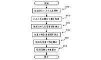
<処理フローチャート>
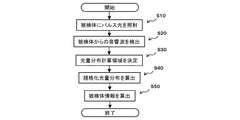
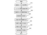
以上に説明した処理を実現するための処理フローチャートを説明する。図3は、本実施形態に係る光音響測定装置が実行する処理のフローチャート図である。
<Processing flowchart>
A process flowchart for realizing the process described above will be described. FIG. 3 is a flowchart of processing performed by the photoacoustic measurement apparatus according to the present embodiment.
まず、ステップS10で、光照射部10から被検体にパルス光(照射光)を照射する。
次に、ステップS20で、音響波検出部20で、被検体から発生した音響波を検出し、電気信号に変換して、信号処理部30が有するメモリ34に格納する。なお、照射光の照射が複数回行われる場合、パルス光の照射と信号取得(ステップS1およびS2)が繰り返し実行される。そのため、照射光の照射と、音響波検出のタイミングは同期している必要がある。
First, in step S10, pulsed light (irradiation light) is irradiated from the
Next, in step S20, the acoustic
次に、ステップS30で、光量分布計算領域決定部31が、光量分布を計算する対象の領域(光量分布計算領域)を決定する。当該ステップでは、前述したように、照射光が被検体に入射する際の、被検体表面での分布、被検体の形状、被検体の平均吸収係数、平均散乱係数に基づいて、照射光量が十分強いと判定された領域を決定し、光量分布計算領域とする。なお、光量分布計算領域は、探触子の指向性や帯域感度などから得られる空間感度分布に基づいて設定してもよいし、観察を所望する光吸収体の吸収係数や大きさから、SN比を算出し、当該SN比と閾値との比較結果に基づいて設定してもよい。 Next, in step S30, the light quantity distribution calculation area determination unit 31 determines a target area (light quantity distribution calculation area) for which the light quantity distribution is to be calculated. In the step, as described above, when the irradiation light enters the object, the amount of irradiation light is sufficient based on the distribution on the object surface, the shape of the object, the average absorption coefficient of the object, and the average scattering coefficient. An area determined to be strong is determined, and is set as a light quantity distribution calculation area. The light amount distribution calculation area may be set based on the spatial sensitivity distribution obtained from the directivity of the probe, the band sensitivity, etc., or from the absorption coefficient or the size of the light absorber desired for observation, SN The ratio may be calculated and set based on the comparison result between the SN ratio and the threshold value.
次に、ステップS40で、規格化光量分布取得部32が、規格化された照射光の分布(規格化照射光分布O’)と、被検体の平均吸収係数、平均散乱係数に基づいて、光量分布計算領域における規格化光量分布を算出する。
次に、ステップS50で、被検体情報算出部33が、被検体情報を算出する。具体的には、ステップS40で算出された規格化光量分布に、照射光の総光強度を乗算し、光量分布を取得する。そして、検出信号に、任意の再構成手法を適用して初期音圧分布を取得し、式(1)に基づいて吸収係数分布を取得する。なお、本例では吸収係数分布を取得したが、異なる波長に対応する吸収係数分布をそれぞれ取得することで、任意の成分の濃度分布(例えば酸素飽和度など)を算出してもよい。
算出された吸収係数分布は、不図示の表示装置を通して、装置のオペレータに提示される。
Next, in step S40, the normalized light amount distribution acquisition unit 32 determines the amount of light based on the normalized distribution of the irradiation light (normalized irradiation light distribution O '), the average absorption coefficient of the object, and the average scattering coefficient. The normalized light amount distribution in the distribution calculation area is calculated.
Next, in step S50, the subject information calculation unit 33 calculates subject information. Specifically, the total light intensity of the irradiation light is multiplied by the normalized light amount distribution calculated in step S40 to acquire the light amount distribution. Then, an arbitrary reconstruction method is applied to the detection signal to acquire an initial sound pressure distribution, and an absorption coefficient distribution is acquired based on Expression (1). Although the absorption coefficient distribution is acquired in this example, the concentration distribution (for example, oxygen saturation etc.) of an arbitrary component may be calculated by acquiring absorption coefficient distributions corresponding to different wavelengths.
The calculated absorption coefficient distribution is presented to the operator of the apparatus through a display (not shown).
なお、本実施形態では、測定開始時に、規格化照射光分布および規格化光量分布を算出し、以降の測定において利用したが、予め照射光や被検体の特性がわかっている場合、規格化照射光分布や規格化光量分布を予め記憶しておき、用いるようにしてもよい。また、異なる照射光や被検体に対応する、複数の規格化照射光分布や規格化光量分布を予め記憶しておき、選択して用いるようにしてもよい。
規格化照射光分布は、被検体に照射光が入射する位置における照射光の2次元プロファ
イルを、カメラなどを用いて予め測定し、2次元プロファイルのピクセルの総和が1になるように規格化することで取得する。また、規格化照射光分布から拡散方程式や輸送方程式を用いて規格化光量分布を算出する。
In the present embodiment, the normalized irradiation light distribution and the normalized light amount distribution are calculated at the start of measurement and used in the subsequent measurements, but if the characteristics of the irradiation light and the object are known in advance, the standardized irradiation The light distribution and the normalized light amount distribution may be stored in advance and used. Also, a plurality of normalized irradiation light distributions and normalized light amount distributions corresponding to different irradiation lights and objects may be stored in advance and selected and used.
The normalized irradiation light distribution is measured by using a camera or the like in advance to measure the two-dimensional profile of the irradiation light at the position where the irradiation light is incident on the object, and normalizes the sum of the pixels of the two-dimensional profile to 1 To get by. In addition, the normalized light amount distribution is calculated from the normalized irradiation light distribution using a diffusion equation and a transport equation.
また、規格化光量分布の算出においては、拡散方程式や輸送方程式を用いて光量分布を算出し、得られた結果を規格化してもよい。例えば、初回のパルス光照射において、従来の方法で光量分布を取得し、当該光量分布を規格化したうえで保持し、2回目以降の照射において利用するようにしてもよい。すなわち、規格化光量分布を求めるために照射されたパルス光以外のパルス光に由来する信号に基づいて、被検体の特性情報を取得してもよい。
規格化された光量分布を用いて被検体内の光量分布を算出することができれば、どのような方法を用いてもよい。
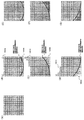
なお、規格化照射光分布と照射光強度の積から算出した、各照射における照射光分布を足し合わせたデータである総和平均照射光分布を使って総和平均光量分布を算出してもよい。その手法について図13を用いて説明する。
図13(A)は、規格化照射光分布ILD_N(rr)を示す図である。図2に示すように、状態1、状態2、状態3の3か所で測定する場合、図13(B)で示したような、照射3回分の照射光分布の総和平均ILDは下記の式のように表わされる。
ILD(r)=(ILD_N(FS(r,SP1))xE1+ILD_N(FS(r,
SP2)xE2+ILD_N(FS(r,SP3))xE3)/3
このようにして求めた総和平均照射光分布ILD(r)から、拡散方程式や輸送方程式を用いて、光量分布Φ(r)を算出することができる(図13(C))。
In the calculation of the normalized light amount distribution, the light amount distribution may be calculated using a diffusion equation or a transport equation, and the obtained result may be normalized. For example, in the first pulse light irradiation, the light amount distribution may be acquired by a conventional method, and the light amount distribution may be standardized and then held and used in the second and subsequent irradiations. That is, the characteristic information of the subject may be acquired based on a signal derived from pulsed light other than the pulsed light irradiated to obtain the normalized light amount distribution.
Any method may be used as long as the light intensity distribution in the subject can be calculated using the normalized light intensity distribution.
The total average light amount distribution may be calculated using a total average irradiation light distribution which is data obtained by adding the irradiation light distribution in each irradiation calculated from the product of the normalized irradiation light distribution and the irradiation light intensity. The method will be described with reference to FIG.
FIG. 13A is a diagram showing the normalized irradiation light distribution ILD_N (rr). As shown in FIG. 2, in the case of measurement at three points of
ILD (r) = (ILD_N (FS (r, SP1)) × E1 + ILD_N (FS (r,
SP2) xE2 + ILD_N (FS (r, SP3)) x E3) / 3
The light amount distribution ((r) can be calculated using the diffusion equation and the transport equation from the total average irradiation light distribution ILD (r) obtained in this manner (FIG. 13 (C)).
(第二の実施形態)
第二の実施形態に係る光音響測定装置は、二枚の保持板を用いて被検者の乳房を圧迫保持し、当該乳房中の酸素飽和度の分布を画像化する装置である。
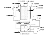
図4は、第二の実施形態に係る光音響測定装置のシステム構成図である。なお、第一の実施形態で述べた構成と同一の構成については、同一の参照符号を付し、説明は省略する。
Second Embodiment
The photoacoustic measurement apparatus according to the second embodiment is an apparatus that compresses and holds the breast of a subject using two holding plates, and images the distribution of oxygen saturation in the breast.
FIG. 4 is a system configuration diagram of the photoacoustic measurement apparatus according to the second embodiment. In addition, about the structure same as the structure described in 1st embodiment, the same referential mark is attached | subjected and description is abbreviate | omitted.
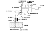
第二の実施形態に係る光音響測定装置は、光照射部10として、光源11、導波路12、照射光学系13、第一の走査機構14を有している。
光源11は、Nd:YAG励起のTi:saレーザであり、30ナノ秒のパルス幅を持つパルス光を10Hzで照射できる。なお、光源11は、出射するパルス光の波長を、756nmと797nmの二種類に切り替えることができる。
導波路12は、光バンドルファイバであり、光源11から出射したパルス光を照射光学系13へ導光する手段である。
照射光学系13は、照射光を被検体に照射する手段である。具体的には、拡大レンズと拡散板で構成され、導波路12から出射したパルス光を、所定の照射密度で被検体2に照射できるようになっている。
第一の走査機構14は、パルスモータを用いて、レールに沿って照射光学系13を水平に移動させるための走査機構である。レールは、第一の保持板14に対して平行に設置されており、照射光学系13を、図の上下方向と奥行き方向の二次元方向に移動させることができる。
なお、第一の走査機構には、照射光学系13の位置を検出するための機構(例えば、照射光を検出する光検出器)が備わっており、検出した位置を、信号処理部30へ送信する。また、光源11から出射される照射光のエネルギーについての情報も、信号処理部30へ送信される。これにより、1パルスあたりの総光強度を算出することができる。
The photoacoustic measurement apparatus according to the second embodiment includes a light source 11, a waveguide 12, an irradiation optical system 13, and a first scanning mechanism 14 as the
The light source 11 is a Ti: sa laser excited by Nd: YAG, and can emit pulsed light having a pulse width of 30 nanoseconds at 10 Hz. In addition, the light source 11 can switch the wavelength of the pulsed light to radiate | emit to two types, 756 nm and 797 nm.
The waveguide 12 is an optical bundle fiber, and is a means for guiding the pulsed light emitted from the light source 11 to the irradiation optical system 13.
The irradiation optical system 13 is a means for irradiating the object with the irradiation light. Specifically, it is configured of a magnifying lens and a diffusion plate, and the pulse light emitted from the waveguide 12 can be irradiated to the subject 2 at a predetermined irradiation density.
The first scanning mechanism 14 is a scanning mechanism for moving the irradiation optical system 13 horizontally along the rail using a pulse motor. The rails are installed in parallel to the first holding plate 14 and can move the irradiation optical system 13 in the two-dimensional direction of the vertical direction and the depth direction of the drawing.
The first scanning mechanism includes a mechanism for detecting the position of the irradiation optical system 13 (for example, a light detector for detecting irradiation light), and transmits the detected position to the
本実施形態では、被検体を、平行平板である第一の保持板41および第二の保持板42によって、挟み込む形で保持する。これにより、保持板に接している位置の被検体表面の形状が保持板の形状に規定される。第一の保持板41および第二の保持板42は、光と音響波の両方に対する透過性を有するポリメチルペンテンを材料とする。
また、第一の保持板41または第二の保持板42は、互いの間隔が変わるように移動可
能に構成されている。なお、移動する保持板は、どちらか片方であってもよいし、両方であってもよい。また、第一の保持板41と第二の保持板42の間隔は、計算処理部4へ送信され、被検体の形状情報として利用される。
In the present embodiment, the subject is held in a sandwiched manner by the first holding plate 41 and the second holding plate 42 which are parallel flat plates. Thus, the shape of the surface of the subject at a position in contact with the holding plate is defined as the shape of the holding plate. The first holding plate 41 and the second holding plate 42 are made of polymethylpentene having transparency to both light and acoustic waves.
Further, the first holding plate 41 or the second holding plate 42 is configured to be movable so that the distance between the first holding plate 41 and the second holding plate 42 changes. The moving holding plate may be either one or both. Further, the distance between the first holding plate 41 and the second holding plate 42 is transmitted to the calculation processing unit 4 and used as shape information of the subject.
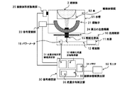
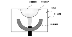
また、第二の実施形態に係る光音響測定装置は、音響波検出部20として、探触子21、信号変換部22、第二の走査機構23を有している。
探触子21は、1×1mmサイズの、中心周波数2MHzの帯域100%のcMut素子を20×30個並べた二次元アレイ探触子である。探触子21と第二の保持板42との間は、音響インピーダンスの整合をとるため、ひまし油で満たされている。
信号変換部22は、探触子21が取得した検出信号を増幅し、電気信号をアナログ信号からデジタル信号に変換する手段である。変換された信号は、信号処理部30へ送信される。
第二の走査機構23は、パルスモータを用いて、レールに沿って探触子21を水平に移動させるための走査機構である。レールは、第二の保持板42に対して平行に設置されており、探触子21を、図の上下方向と奥行き方向の二次元方向に移動させることができる。また、第二の走査機構23は、第一の走査機構14と連動している。すなわち、照射光が被検体に当たる位置の裏側に探触子21が来るように制御される。
Further, the photoacoustic measurement apparatus according to the second embodiment includes, as the acoustic
The probe 21 is a two-dimensional array probe in which 20 × 30 cMut elements of 1 × 1 mm size and 100% band of center frequency 2 MHz are arranged. The space between the probe 21 and the second holding plate 42 is filled with castor oil in order to match the acoustic impedance.
The signal conversion unit 22 is a unit that amplifies the detection signal acquired by the probe 21 and converts an electrical signal from an analog signal to a digital signal. The converted signal is transmitted to the
The second scanning mechanism 23 is a scanning mechanism for moving the probe 21 horizontally along the rail using a pulse motor. The rails are installed in parallel to the second holding plate 42, and can move the probe 21 in the two-dimensional direction of the vertical direction and the depth direction of the drawing. Further, the second scanning mechanism 23 is interlocked with the first scanning mechanism 14. That is, the probe 21 is controlled to come to the back side of the position where the irradiation light hits the object.
本実施形態における信号処理部30は、第一の実施形態と同様に、光量分布計算領域決定部31、規格化光量分布取得部32、被検体情報算出部33を有している。本実施形態では、信号処理部30は、ワークステーションであり、光量分布計算領域決定部31、規格化光量分布取得部32、被検体情報算出部33は、当該ワークステーションで動作するプログラムである。
As in the first embodiment, the
第二の実施形態では、信号処理部30が、光源11から、出射する照射光のエネルギーについての情報を取得し、被検体に照射されるパルス光の総光強度に変換したうえで、これを、取得した規格化光量分布に乗算し、吸収係数の計算に用いる光量分布を取得する。
また、信号処理部30は、被検体2の平均吸収係数、平均散乱係数を、入力部60経由で取得し、規格化光量分布取得部32が光量分布を計算する際に用いる。
さらに、信号処理部30は、第一の保持板41と第二の保持板42との距離を取得し、二つの保持板の間にすべて被検体2があるものと仮定して、光量分布を取得する。
In the second embodiment, the
Further, the
Furthermore, the
第一の実施形態では、一波長のみを用いて吸収係数分布を取得したが、第二の実施形態に係る信号処理部30は、二つの波長を用いて、吸収係数分布をそれぞれ取得し、式(16)を用いて、被検体内における酸素飽和度の分布を算出する。
StO=(μi756(r)×εHbR756−μi797(r)×εHbR797)/(μi756
(r)×(εHbR756−εHbO756)−μi797(r)×(εHbR797−εHbO797
)) ・・・式(16)
In the first embodiment, the absorption coefficient distribution is acquired using only one wavelength, but the
StO = (. Mu.i 756 (r) .times..epsilon.HbR 756 -.mu.i 797 (r) .times..epsilon.HbR 797 ) / (. Mu.i 756 )
(R) × (εHbR 756 -εHbO 756 ) -μi 797 (r) × (εHbR 797 -εHbO 797
)) ... Formula (16)
ここで、εHbR756は、還元ヘモグロビンの、波長756nmにおける吸収係数であ
り、εHbR797は、還元ヘモグロビンの、波長797nmにおける吸収係数である。ま
た、εHbO756は、酸化ヘモグロビンの波長756nmにおける吸収係数であり、εH
bO797は、酸化ヘモグロビンの波長797nmにおける吸収係数である。また、μi756(r)は、波長756nmのパルス光で測定して得られた吸収係数分布であり、μi797
(r)は、波長797nmのパルス光で測定して得られた吸収係数分布である。
Here, εHbR 756 is an absorption coefficient of reduced hemoglobin at a wavelength of 756 nm, and εHbR 797 is an absorption coefficient of reduced hemoglobin at a wavelength of 797 nm. Further, εHbO 756 is an absorption coefficient of oxyhemoglobin at a wavelength of 756 nm, and εH
bO 797 is the absorption coefficient of oxyhemoglobin at a wavelength of 797 nm. Further, μi 756 (r) is an absorption coefficient distribution obtained by measurement with pulsed light of wavelength 756 nm, and μi 797 (r)
(R) is an absorption coefficient distribution obtained by measurement with pulsed light of wavelength 797 nm.
第二の実施形態に係る信号処理部30が行う処理のフローチャートを図5に示す。
図5のフローチャートは、ステップS10の完了後に、被検体に対して照射されたパルス光の光量を取得するステップ(ステップS15)が追加されるという点において、第一の実施形態(図3)と相違する。
ステップS15では、光源への投入エネルギーと、予め与えられた係数(当該エネルギーを照射光の総光強度に変換するための係数)を用い、各位置における照射光の総光強度を算出する。算出された光強度は、ステップS50において、規格化光量分布を、実際の光量分布に変換する際に用いられる。
また、第二の実施形態では、ステップS10〜S50の処理を波長ごとに実行し、得られた複数の吸収係数分布に基づいて、酸素飽和度を算出する。算出された酸素飽和度は、モニタ50を通して、装置のオペレータに提示される。
The flowchart of the process which the
The flowchart of FIG. 5 is different from the first embodiment (FIG. 3) in that the step (step S15) of acquiring the light quantity of the pulsed light emitted to the subject after the completion of step S10 is added. It is different.
In step S15, the total light intensity of the irradiation light at each position is calculated using the energy input to the light source and the coefficient given in advance (the coefficient for converting the energy into the total light intensity of the irradiation light). The calculated light intensity is used when converting the normalized light amount distribution into an actual light amount distribution in step S50.
In the second embodiment, the processes of steps S10 to S50 are performed for each wavelength, and the oxygen saturation is calculated based on the obtained plurality of absorption coefficient distributions. The calculated oxygen saturation is presented to the operator of the device through the monitor 50.
第二の実施形態に係る光音響測定装置では、被検体の形状が保持板によって規定されており、照射光が、被検体の表面に対してほぼ同じパターンで照射される。すなわち、規格化照射光分布を予めひとつ求めておけば、全ての照射において利用することができる。
なお、平均吸収係数と平均散乱係数は、オペレータによって入力させてもよいし、予め測定した値を保持しておき、それを用いてもよい。
In the photoacoustic measurement apparatus according to the second embodiment, the shape of the subject is defined by the holding plate, and the irradiation light is emitted to the surface of the subject in substantially the same pattern. That is, if one normalized irradiation light distribution is obtained in advance, it can be used in all irradiations.
The average absorption coefficient and the average scattering coefficient may be input by an operator or may be used by holding values measured in advance.
(第三の実施形態)
第三の実施形態に係る光音響測定装置は、乳房中の吸収係数分布を画像化する装置であって、探触子21と照射光学系13を一つの筐体80内に格納し、被検体に押し付けて測定を行う、ハンドヘルド型の装置である。
図6は、第三の実施形態に係る光音響測定装置のシステム構成図である。なお、第一の実施形態で述べた構成と同一の構成については、同一の参照符号を付し、説明は省略する。
Third Embodiment
The photoacoustic measurement apparatus according to the third embodiment is an apparatus for imaging the absorption coefficient distribution in the breast, and stores the probe 21 and the irradiation optical system 13 in one housing 80, and the subject It is a handheld device that performs measurement by pressing it on the
FIG. 6 is a system configuration diagram of the photoacoustic measurement apparatus according to the third embodiment. In addition, about the structure same as the structure described in 1st embodiment, the same referential mark is attached | subjected and description is abbreviate | omitted.
第三の実施形態に係る光音響測定装置は、光照射部10として、光源11、導波路12、照射光学系13、パワーメータ15を有している。
光源11は、アレキサンドライトレーザであり、100ナノ秒のパルス幅を持つパルス光を、波長700nm〜800nmの範囲で、20Hzで照射できる。
導波路12は、光バンドルファイバであり、光源11から出射したパルス光を、照射光学系13に導光する手段である。また、光源から出射したパルス光の一部を分岐させ、パワーメータ15に導光する手段である。
照射光学系13は、照射光を被検体に照射する手段である。具体的には、拡大レンズと拡散板で構成され、導波路12から出射されたパルス光を、所定の照射密度で被検体2に照射できるようになっている。
パワーメータ15は、光源から出射したパルス光の一部の光強度を検出し、計測する手段(照射光強度取得手段)である。検出結果は、信号処理部30へ送信される。
The photoacoustic measurement apparatus according to the third embodiment includes a light source 11, a waveguide 12, an irradiation optical system 13, and a
The light source 11 is an alexandrite laser, and can emit pulsed light having a pulse width of 100 nanoseconds at a wavelength of 700 nm to 800 nm at 20 Hz.
The waveguide 12 is an optical bundle fiber, and is a means for guiding the pulsed light emitted from the light source 11 to the irradiation optical system 13. Further, it is a means for branching a part of the pulse light emitted from the light source and guiding the branched light to the
The irradiation optical system 13 is a means for irradiating the object with the irradiation light. Specifically, it is configured by a magnifying lens and a diffusion plate, and the pulsed light emitted from the waveguide 12 can be irradiated to the subject 2 at a predetermined irradiation density.
The
また、第三の実施形態に係る光音響測定装置は、音響波検出部20として、探触子21、信号変換部22を有している。探触子21は、図面奥行き方向に、1mmのピエゾ素子を20個並べ、音響レンズを追加した一次元アレイ探触子である。探触子21は、素子の配列方向(図面奥行き方向)と、図面上下方向からなる、二次元面の信号のみを検出可能な構成となっている。
信号変換部22は、探触子21が取得した検出信号を増幅し、電気信号をアナログ信号からデジタル信号に変換する手段である。変換された信号は、信号処理部30へ送信される。
In addition, the photoacoustic measurement apparatus according to the third embodiment includes a probe 21 and a signal conversion unit 22 as the acoustic
The signal conversion unit 22 is a unit that amplifies the detection signal acquired by the probe 21 and converts an electrical signal from an analog signal to a digital signal. The converted signal is transmitted to the
第三の実施形態においても、信号処理部30は、光量分布計算領域決定部31、規格化光量分布取得部32、被検体情報算出部33を有している。
Also in the third embodiment, the
本実施形態では、探触子21が有する音響素子が一次元配列であるため、音響波を検出できるのは、探触子正面の領域(以下、被検体情報取得領域)のみである。そのため、当該被検体情報取得領域についてのみ光量分布を取得すれば、処理を行うことができる。
しかし、光量分布を計算する為には、照射光が被検体表面に照射される位置を含んだ領域を計算する必要がある。また、光量分布計算領域の境界における境界条件が、算出された光量に大きく影響を与える領域が、境界から数mm程度ある。そのため、本実施形態では、被検体情報取得領域よりも若干大きい領域を光量分布計算領域として設定する。具体的には、被検体情報取得領域より10mm大きい領域を、光量分布計算領域とする。
In the present embodiment, since the acoustic elements included in the probe 21 are one-dimensional array, only the area in front of the probe (hereinafter, an object information acquisition area) can detect acoustic waves. Therefore, processing can be performed if the light amount distribution is acquired only for the subject information acquisition region.
However, in order to calculate the light quantity distribution, it is necessary to calculate an area including the position where the irradiation light is irradiated to the object surface. In addition, there is an area in which the boundary condition at the boundary of the light amount distribution calculation area greatly affects the calculated light amount, which is about several mm from the boundary. Therefore, in the present embodiment, a region slightly larger than the object information acquisition region is set as the light amount distribution calculation region. Specifically, a region that is 10 mm larger than the object information acquisition region is taken as a light amount distribution calculation region.
本実施形態では、第二の実施形態と同様に、規格化光量分布取得部32が、照射光の総光強度を規格化した場合の、光量分布計算領域における光量分布(規格化光量分布)を算出する。 In the present embodiment, similarly to the second embodiment, the light amount distribution (normalized light amount distribution) in the light amount distribution calculation area when the normalized light amount distribution acquisition unit 32 normalizes the total light intensity of the irradiation light calculate.
次に、図6を参照して、本実施形態における被検体情報算出部33が行う処理について説明する。本実施形態では、照射光学系13および探触子21の位置を変化させずに、パルス光を複数回照射する。
例えば、パルス光を3回照射する場合、各照射に対する状態を、状態1、状態2、状態3とすると、図7(A)〜(C)のように、それぞれの位置関係は変わらない。
ここで、各状態における照射光の光強度をE1,E2,E3とすると、位置rにある光吸収体3の吸収係数の算出方法は、式(10)より、以下のようになる。
μi(r)=R(S1(r),S2(r),S3(r))/{(ΦN(r)×E1+ΦN(r)×E2+ΦN(r)×E3)/3}
または、式(13)により、以下のようになる。
μi(r)=R(S1(r)/E1,S2(r)/E2,S3(r)/E3)/{(ΦN(r)+ΦN(r)+ΦN(r))/3}
Next, processing performed by the subject information calculation unit 33 in the present embodiment will be described with reference to FIG. In the present embodiment, the pulsed light is irradiated multiple times without changing the positions of the irradiation optical system 13 and the probe 21.
For example, in the case of irradiating pulsed light three times, assuming that the state for each irradiation is
Here, assuming that the light intensities of the irradiation light in each state are E1, E2, and E3, the calculation method of the absorption coefficient of the light absorber 3 at the position r is as follows from Expression (10).
μi (r) = R (S1 (r), S2 (r), S3 (r)) / {(ΦN (r) × E1 + EN (r) × E2 + (N (r) × E3) / 3}
Or it becomes as follows by Formula (13).
μi (r) = R (S1 (r) / E1, S2 (r) / E2, S3 (r) / E3) / {(ΦN (r) + ΦN (r) + (N (r)) / 3}
なお、本実施形態における規格化光量分布取得部32は、筐体が接した面から奥行き方向に被検体が無限に続くものと仮定して、規格化光量分布を算出する。また、被検体2の平均吸収係数、平均散乱係数は、人間の乳房の統計データの平均値を、予め記憶させておき、用いるものとする。 The normalized light amount distribution acquisition unit 32 in the present embodiment calculates the normalized light amount distribution on the assumption that the subject continues infinitely in the depth direction from the surface in contact with the casing. Further, the average absorption coefficient and the average scattering coefficient of the subject 2 are stored in advance in advance using average values of statistical data of human breasts.
第三の実施形態に係る信号処理部30が行う処理のフローチャートは、第二の実施形態(図5)と同様であるが、パワーメータ15が取得したパルス光の光強度に基づいて、照射光の総光強度を算出するステップが追加されるという点において相違する。具体的には、ステップS15にて、パワーメータ15が取得したパルス光の光強度に、予め与えられた係数(計測した光強度を、照射光総光強度に変換するための係数)を乗算し、各位置における照射光の総光強度を算出する。算出された光強度は、ステップS50において、規格化光量分布を、実際の光量分布に変換する際に用いられる。
また、ステップS30の処理において、前述した方法によって光量計算領域を設定するという点において相違する。他のステップは、第二の実施形態で示したものと同様である。
なお、第三の実施形態では、第二の実施形態と同様に、最初に、規格化した照射光分布ILD_N(rr)と照射光強度を使って、総和平均照射光分布ILD(r)を算出してから、初期音圧R(S1(r),S2(r),S3(r))を除するための光量を算出してもよい。
The flowchart of the process performed by the
Further, in the process of step S30, the present embodiment is different in that the light amount calculation area is set by the method described above. The other steps are similar to those shown in the second embodiment.
In the third embodiment, similarly to the second embodiment, first, the total irradiation light distribution ILD (r) is calculated using the normalized irradiation light distribution ILD_N (rr) and the irradiation light intensity. After that, the light quantity for dividing the initial sound pressure R (S1 (r), S2 (r), S3 (r)) may be calculated.
(第四の実施形態)
第四の実施形態に係る光音響測定装置は、乳房中の相対的なヘモグロビン濃度分布を画像化する装置であって、お椀状の形状をした探触子を用いて測定を行う装置である。
図8は、第四の実施形態に係る光音響測定装置のシステム構成図である。なお、第一の実施形態で述べた構成と同一の構成については、同一の参照符号を付し、説明は省略する。
Fourth Embodiment
The photoacoustic measurement apparatus according to the fourth embodiment is an apparatus for imaging relative hemoglobin concentration distribution in the breast, and is an apparatus for performing measurement using a probe having a bowl-like shape.
FIG. 8 is a system configuration diagram of the photoacoustic measurement apparatus according to the fourth embodiment. In addition, about the structure same as the structure described in 1st embodiment, the same referential mark is attached | subjected and description is abbreviate | omitted.
第四の実施形態に係る光音響測定装置は、光照射部10として、光源11、導波路12、照射光学系13、パワーメータ15を有している。
光源11は、アレキサンドライトレーザであり、100ナノ秒のパルス幅を持つ、波長797nmのパルス光を、20Hzで照射できる。
導波路12は、レーザ光を空間伝播させるための、反射ミラー付きのアームであり、光源11から出射したパルス光を、照射光学系13に導光する手段である。また、光源から出射したパルス光の一部を分岐させ、パワーメータ15に導光する手段である。
照射光学系13は、照射光を被検体に照射する手段である。具体的には、拡大レンズと拡散板で構成され、導波路12から出射されたパルス光を、所定の照射密度で被検体2に照射できるようになっている。
パワーメータ15は、光源から出射したパルス光の一部の光強度を検出し、計測する手段である。検出結果は、信号処理部30へ送信される。
The photoacoustic measurement apparatus according to the fourth embodiment includes a light source 11, a waveguide 12, an irradiation optical system 13, and a
The light source 11 is an alexandrite laser, and can emit pulsed light with a wavelength of 797 nm at 20 Hz with a pulse width of 100 nanoseconds.
The waveguide 12 is an arm with a reflecting mirror for space propagation of the laser light, and is a means for guiding the pulsed light emitted from the light source 11 to the irradiation optical system 13. Further, it is a means for branching a part of the pulse light emitted from the light source and guiding the branched light to the
The irradiation optical system 13 is a means for irradiating the object with the irradiation light. Specifically, it is configured by a magnifying lens and a diffusion plate, and the pulsed light emitted from the waveguide 12 can be irradiated to the subject 2 at a predetermined irradiation density.
The
また、第四の実施形態に係る光音響測定装置は、音響波検出部20として、探触子21、信号変換部22を有している。
探触子21は、半球状の形状をしたお椀型の保持部材の内側表面に、球の中心を向いたピエゾ素子を512個、フィボナッチ配列によって配列したものである。
信号変換部22は、探触子21が取得した検出信号を増幅し、電気信号をアナログ信号からデジタル信号に変換する手段である。変換された信号は、信号処理部30へ送信される。
In addition, the photoacoustic measurement apparatus according to the fourth embodiment includes a probe 21 and a signal conversion unit 22 as the acoustic
The probe 21 is a Fibonacci arrangement in which 512 piezoelectric elements facing the center of a sphere are arranged on the inner surface of a bowl-shaped holding member in a hemispherical shape.
The signal conversion unit 22 is a unit that amplifies the detection signal acquired by the probe 21 and converts an electrical signal from an analog signal to a digital signal. The converted signal is transmitted to the
第四の実施形態に係る光音響測定装置では、探触子21と照射光学系13が一体になっており、図8に示すように、お椀型探触子の底面から、球の中心側方向にパルス光を照射する構成となっている。また、探触子21と照射光学系13は水槽91の中に配置されており、水槽91内を水92で満たすことで、被検体2との音響インピーダンスを整合させている。また、探触子21および照射光学系13は、第三の走査機構24によって、被検体に対する相対的な位置を変更できるようになっている。
In the photoacoustic measurement apparatus according to the fourth embodiment, the probe 21 and the irradiation optical system 13 are integrated, and as shown in FIG. 8, the direction from the bottom of the bowl-shaped probe toward the center of the sphere Is configured to emit pulsed light. Further, the probe 21 and the irradiation optical system 13 are disposed in the water tank 91, and by filling the water tank 91 with
第四の実施形態では、照射光学系13が被検体と密着していないため、被検体の照射面が変わると、被検体内の光量分布が変化してしまう。すなわち、前述した方法では、規格化光量分布を正しく算出することができない。
そこで、本実施形態では、被検体形状取得部25によって、被検体の形状を計測し、計測結果を用いて、規格化光量分布を補正する。被検体形状取得部25は、被検体の形状を取得することができれば、どのような手法を用いてもよい。例えば、複数の位置にカメラを設置して、被検体の投影形状から形状を算出してもよい。また、Time of Flightカメラを用いてもよいし、プロジェクタでパターンを投影し、カメラで撮像することによって形状を取得してもよい。この他にも、超音波を送受信して、被検体と水の音響インピーダンスの違いから形状を抽出してもよいし、光音響特性を使って、被検体表面の光の吸収により出る信号から形状を抽出してもよい。
取得した形状を用いて、規格化光量分布を補正する方法については後述する。
In the fourth embodiment, since the irradiation optical system 13 is not in intimate contact with the subject, when the irradiation surface of the subject changes, the light quantity distribution in the subject changes. That is, the method described above can not calculate the normalized light amount distribution correctly.
Therefore, in the present embodiment, the shape of the object is measured by the object
The method of correcting the normalized light amount distribution using the acquired shape will be described later.
第四の実施形態においても、信号処理部30は、光量分布計算領域決定部31、規格化光量分布取得部32、被検体情報算出部33を有している。また、被検体の形状に応じて、規格化光量分布を補正するための光量分布補正部35を有している。
Also in the fourth embodiment, the
まず、光量分布計算領域決定部31が、光量分布計算領域とは別に、被検体領域を決定する。被検体領域とは、被検体形状全体が入るように直方体形状で囲われた領域である。被検体領域は、なるべく被検体で満たされるように、また、照射光が垂直に入射できるような面を持っていてもよい。本実施形態では、図面横方向をX軸、奥行き方向をY軸、上下方向をZ軸とした場合に、X軸方向に24mm、Y軸方向に24mm、Z軸方向に10
mmの直方体の領域を被検体領域とした。
First, the light quantity distribution calculation area determination unit 31 determines an object area separately from the light quantity distribution calculation area. The subject region is a region surrounded by a rectangular parallelepiped shape so that the entire subject shape is included. The object region may have a surface which is filled with the object as much as possible and in which the irradiation light can be perpendicularly incident. In the present embodiment, when the horizontal direction in the drawing is the X axis, the depth direction is the Y axis, and the vertical direction is the Z axis, 24 mm in the X axis direction, 24 mm in the Y axis direction, and 10 in the Z axis direction.
An area of a rectangular parallelepiped of mm was taken as a subject area.
また、光量分布計算領域決定部31は、第二の実施形態と同様の方法で光量分布計算領域を決定する。本実施形態では、光量分布計算領域を、10mm×10mm×10mmの大きさとする。また、規格化光量分布取得部32が、規格化光量分布を、第二の実施形態と同様の方法で算出する。 Further, the light quantity distribution calculation area determination unit 31 determines the light quantity distribution calculation area by the same method as the second embodiment. In the present embodiment, the light amount distribution calculation area has a size of 10 mm × 10 mm × 10 mm. Further, the normalized light amount distribution acquisition unit 32 calculates the normalized light amount distribution by the same method as the second embodiment.
前述したように、本実施形態では、探触子および照射光学系が、被検体に対して密着していないため、照射光が被検体に入射する際の被検体表面の形状が、照射ごとに変わってしまう。すなわち、前述した方法では、規格化光量分布を正確に算出することができない。
そこで、本実施形態では、生成した規格化光量分布を、被検体の形状に基づいて補正し、補正後の規格化光量分布を用いて、被検体内の光量分布を推定する。
As described above, in the present embodiment, the probe and the irradiation optical system are not in intimate contact with the object, so the shape of the object surface when the irradiation light is incident on the object is determined for each irradiation. It will change. That is, the method described above can not accurately calculate the normalized light amount distribution.
Therefore, in the present embodiment, the generated normalized light amount distribution is corrected based on the shape of the object, and the light amount distribution in the object is estimated using the corrected light amount distribution.
図9は、探触子21および照射光学系13が、被検体に対して、異なる位置にある場合を示した図である。ここでは、図9(A)、図9(B)、図9(C)で示した位置関係を、それぞれ、状態1、状態2、状態3とする。
本実施形態では、光量分布補正部35が、光量分布算出領域において求めた規格化光量分布を、被検体の形状に基づいて補正(変形)させる。すなわち、光量分布補正部35が、規格化光量分布の座標が被検体の外形の座標に対応するように、規格化光量分布の座標を補正する。
FIG. 9 is a view showing a case where the probe 21 and the irradiation optical system 13 are at different positions with respect to the object. Here, the positional relationships shown in FIGS. 9A, 9B, and 9C are referred to as
In the present embodiment, the light quantity distribution correction unit 35 corrects (deforms) the normalized light quantity distribution obtained in the light quantity distribution calculation area based on the shape of the object. That is, the light amount distribution correction unit 35 corrects the coordinates of the normalized light amount distribution such that the coordinates of the normalized light amount distribution correspond to the coordinates of the outer shape of the object.
まず、図10(A)に示したように、規格化光量分布をX軸、Y軸、Z軸に平行に切った1mmの立法メッシュによって分割する。次に、図10(B),図10(C),図10(D)で示したように、1mmの立法メッシュで分割した規格化光量分布を、Z方向へ1mm単位でスライドさせ、状態ごとに、被検体の形状に合わせる。この時、スライドによって光量分布計算領域からはみ出した部分(符号1001A、1001B、1001C)は削除し、スライドによって値が無くなった部分(符号1002A、1002B、1002C)には、規格化光量分布の最大値を入れる。
このような処理を行うと、図10(E),図10(F),図10(G)のように、補正後の規格化光量分布が得られる。
そして、被検体情報算出部33は、第二の実施形態における規格化光量分布の代わりに、補正後の規格化光量分布を用いて、第二の実施形態と同様の方法で、被検体内の吸収係数を算出する。
First, as shown in FIG. 10A, the normalized light amount distribution is divided by a 1 mm cubic mesh cut parallel to the X axis, Y axis, and Z axis. Next, as shown in FIG. 10 (B), FIG. 10 (C), and FIG. 10 (D), the normalized light amount distribution divided by 1 mm cubic mesh is slid in the Z direction in 1 mm units. In accordance with the shape of the subject. At this time, the portions (
When such processing is performed, the normalized light amount distribution after correction can be obtained as shown in FIGS. 10 (E), 10 (F), and 10 (G).
Then, the object information calculation unit 33 uses the normalized light amount distribution after correction instead of the normalized light amount distribution in the second embodiment, and uses the inside of the object in the same manner as in the second embodiment. Calculate the absorption coefficient.
第四の実施形態に係る信号処理部30が行う処理のフローチャートは、第二の実施形態(図5)と同様であるが、被検体の形状を測定するステップが追加されるという点において相違する。具体的には、ステップS25にて、前述した方法によって、パルス光が照射される面の形状を測定する。なお、被検体の形状測定は、被検体の形状や位置が前回の測定から変わった場合にのみ行う。
また、光量分布計算領域に存在する被検体の形状に合わせて、規格化光量分布を補正するステップ(ステップS45)が追加されるという点において相違する。補正の方法は、例えば前述したように、照射光の照射方向から被検体奥行き方向に向かって、各メッシュに対応する値をずらす方法を用いることができる。この他にも、アフィン変換などを使って補正を行ってもよい。光量分布計算領域からはみ出した値は削除してもよい。また、値がなくなったメッシュには、規格化光量分布の最大値を代入してもよい。
他のステップは、第二の実施形態で示したものと同様である。
The flowchart of the process performed by the
Further, the present embodiment is different in that a step (step S45) of correcting the normalized light amount distribution is added according to the shape of the object present in the light amount distribution calculation area. As the correction method, for example, as described above, it is possible to use a method of shifting the value corresponding to each mesh from the irradiation direction of the irradiation light toward the subject depth direction. Besides this, correction may be performed using an affine transformation or the like. The values which are out of the light amount distribution calculation area may be deleted. In addition, the maximum value of the normalized light amount distribution may be substituted for the mesh whose value is lost.
The other steps are similar to those shown in the second embodiment.
なお、被検体を挿入する部分に、被検体の形状を規定するための部材を設けてもよい。例えば、図12に示したカップ93のように、測定中に被検体を押し付けて保持するため
の保持部材を設ける。これにより、照射面の形状が、予め定められた形状となるため、被検体の形状測定を省略することができる。なお、保持部材の形状は、被検体形状取得部25に予め記憶させてもよい。
In addition, a member for defining the shape of the subject may be provided in a portion where the subject is inserted. For example, as in a cup 93 shown in FIG. 12, a holding member is provided to press and hold the subject during measurement. As a result, the shape of the irradiation surface becomes a predetermined shape, so that the shape measurement of the subject can be omitted. The shape of the holding member may be stored in advance in the subject
また、保持部材の形状が予め定まっている場合、規格化光量分布の補正を毎回実行する必要はない。例えば、使用する保持部材ごとに補正済みの規格化光量分布を記憶しておき、対応するものを用いるようにしてもよい。
また、第四の実施形態では、第一の実施形態と同様に、最初に、規格化した照射光分布ILD_N(rr)と照射光強度を使って、総和平均照射光分布ILD(r)を算出してから、初期音圧R(S1(r),S2(r),S3(r))を除するための光量を算出し、図10のように形状に沿わせてもよい。
In addition, when the shape of the holding member is determined in advance, it is not necessary to execute the correction of the normalized light amount distribution every time. For example, the corrected normalized light amount distribution may be stored for each holding member to be used, and a corresponding one may be used.
In the fourth embodiment, similarly to the first embodiment, first, the total irradiation light distribution ILD (r) is calculated using the normalized irradiation light distribution ILD_N (rr) and the irradiation light intensity. Thereafter, the amount of light for dividing the initial sound pressure R (S1 (r), S2 (r), S3 (r)) may be calculated to conform to the shape as shown in FIG.
(変形例)
なお、各実施形態の説明は本発明を説明する上での例示であり、本発明は、発明の趣旨を逸脱しない範囲で適宜変更または組み合わせて実施することができる。
例えば、本発明は、前述した手段の少なくとも一部を含む被検体情報取得装置として実施することもできる。また、当該被検体情報取得装置が行う処理方法として実施することもできる。上記処理や手段は、技術的な矛盾が生じない限りにおいて、自由に組み合わせて実施することができる。
(Modification)
The description of each embodiment is an exemplification for describing the present invention, and the present invention can be implemented by being appropriately changed or combined without departing from the scope of the present invention.
For example, the present invention can also be implemented as a subject information acquisition apparatus including at least a part of the aforementioned means. Moreover, it can also implement as the processing method which the said object information acquisition apparatus performs. The above-mentioned processes and means can be freely combined and implemented as long as no technical contradiction arises.
本発明は、記憶装置に記録されたプログラムを読み込み実行することで前述した実施形態の機能を実現するシステムや装置のコンピュータ(又はCPU、MPU等のデバイス)によっても実施することができる。また、例えば、記憶装置に記録されたプログラムを読み込み実行することで前述した実施形態の機能を実現するシステムや装置のコンピュータによって実行されるステップからなる方法によっても、本発明を実施することができる。また、1以上の機能を実現する回路(例えば、FPGAやASIC)によって実行することもできる。この目的のために、上記プログラムは、例えば、ネットワークを通じて、又は、上記記憶装置となり得る様々なタイプの記録媒体(つまり、非一時的にデータを保持するコンピュータ読取可能な記録媒体)から、上記コンピュータに提供される。したがって、上記コンピュータ(CPU、MPU等のデバイスを含む)、上記方法、上記プログラム(プログラムコード、プログラムプロダクトを含む)、上記プログラムを非一時的に保持するコンピュータ読取可能な記録媒体は、いずれも本発明の範疇に含まれる。 The present invention can also be implemented by a computer (or a device such as a CPU or MPU) of a system or apparatus that implements the functions of the above-described embodiments by reading and executing a program recorded in a storage device. Further, for example, the present invention can also be implemented by a method including steps executed by a computer of a system or apparatus for realizing the functions of the above-described embodiments by reading and executing a program recorded in a storage device. . It can also be implemented by circuitry (eg, an FPGA or ASIC) that implements one or more functions. To this end, the program may be, for example, through the network or from various types of recording media that can be the storage device (i.e. from computer readable recording media that hold data non-temporarily) Provided to Therefore, the computer (including devices such as CPU and MPU), the method, the program (including program code and program product), and a computer readable recording medium which holds the program non-temporarily are all It is included in the category of the invention.
10・・・光照射部、20・・・音響波検出部、30・・・信号処理部 10: light irradiator, 20: acoustic wave detector, 30: signal processor
Claims (20)
第1のタイミングに前記被検体に照射されたパルス光の前記被検体表面における照射光分布について、当該第1のタイミングに前記被検体に照射されたパルス光の総光強度を、単位光強度を基準として規格化することにより、規格化された照射光分布である規格化照射光分布を算出し、
前記規格化照射光分布を用いて、前記第1のタイミングに前記被検体に照射されたパルス光の前記被検体内の規格化された光量分布である規格化光量分布を算出し、
前記規格化光量分布に、前記第1のタイミングとは異なる第2のタイミングに前記被検体に照射されたパルス光の総光強度を乗算することにより、前記第2のタイミングに前記被検体に照射されたパルス光の前記被検体内の光量分布を算出し、
前記光量分布と、前記第2のタイミングに前記被検体にパルス光が照射されることにより前記被検体から発生した音響波の検出信号とを用いて、前記被検体の特性情報を取得する処理手段を有する
ことを特徴とする、被検体情報取得装置。 A subject information obtaining apparatus that acquires characteristic information of the object based on the detection decyne No. acoustic wave generated from the subject by Rukoto pulse light is irradiated to the subject,
Regarding the irradiation light distribution on the object surface of the pulse light irradiated to the object at the first timing, the total light intensity of the pulse light irradiated to the object at the first timing is unit light intensity By normalizing as a standard, a normalized irradiation light distribution which is a normalized irradiation light distribution is calculated,
Calculating a normalized light amount distribution which is a normalized light amount distribution in the object of the pulse light irradiated to the object at the first timing using the normalized irradiation light distribution ;
The subject is irradiated with the second timing by multiplying the normalized light amount distribution by the total light intensity of the pulsed light emitted to the subject by a second timing different from the first timing. Calculating the light quantity distribution in the subject of the pulsed light that has been
Before Symbol light amount distribution, by using the detection signal of an acoustic wave generated from the subject by the pulsed light is irradiated to the subject in the second timing, acquires the characteristic information of the subject characterized in that it has a processing hand stage, object information acquiring apparatus.
第1のタイミングに前記被検体に照射されたパルス光の前記被検体内の光量分布を算出し、Calculating a light quantity distribution in the subject of the pulsed light irradiated to the subject at a first timing;
前記光量分布について、前記第1のタイミングに前記被検体に照射されたパルス光の総光強度を、単位光強度を基準として規格化することにより、規格化された光量分布である規格化光量分布を算出し、A normalized light amount distribution which is a normalized light amount distribution by normalizing the total light intensity of the pulse light irradiated to the subject at the first timing with respect to the light amount distribution with reference to a unit light intensity. Calculate
前記規格化光量分布に、前記第1のタイミングとは異なる第2のタイミングに前記被検体に照射されたパルス光の総光強度を乗算することにより、前記第2のタイミングに前記被検体に照射されたパルス光の前記被検体内の光量分布を算出し、The subject is irradiated with the second timing by multiplying the normalized light amount distribution by the total light intensity of the pulsed light emitted to the subject by a second timing different from the first timing. Calculating the light quantity distribution in the subject of the pulsed light that has been
前記光量分布と、前記第2のタイミングに前記被検体にパルス光が照射されることにより前記被検体から発生した音響波の検出信号とを用いて、前記被検体の特性情報を取得する処理手段と、を有するA processing means for acquiring characteristic information of the subject using the light quantity distribution and a detection signal of an acoustic wave generated from the subject by irradiating the subject with pulsed light at the second timing. And
ことを特徴とする、被検体情報取得装置。An object information acquiring apparatus characterized in that.
前記照射手段からのパルス光が照射された前記被検体から発生した音響波を検出して検出信号としての電気信号を出力する音響波検出手段と、Acoustic wave detection means for detecting an acoustic wave generated from the object irradiated with pulsed light from the irradiation means and outputting an electrical signal as a detection signal;
を有することを特徴とする請求項1または2に記載の被検体情報取得装置。The subject information acquiring apparatus according to claim 1 or 2, characterized in that:
前記処理手段は、前記規格化光量分布と、前記光強度測定手段により測定された前記第2のタイミングに前記被検体に照射されたパルス光の総光強度と、を用いて、前記被検体内の光量分布を算出する
ことを特徴とする、請求項3に記載の被検体情報取得装置。 The emitted from the irradiation unit, it has a light intensity measuring means that measure the total light intensity of the pulsed light before being radiated to the subject,
Pre Symbol processing means uses a front KiTadashi Kakuka light amount distribution, the total light intensity before Symbol light intensity the said second timing measured by the measuring means is applied to the specimen is pulsed light, and The subject information acquiring apparatus according to claim 3 , wherein the light quantity distribution in the subject is calculated .
ことを特徴とする、請求項4に記載の被検体情報取得装置。 The processing means, wherein based on the electric signal to obtain an initial sound pressure distribution, by the row Ukoto the operation for dividing the light intensity distribution from the initial sound pressure distribution, to obtain the characteristic information of the subject The object information acquisition apparatus according to claim 4 , wherein
前記処理手段は、前記光強度測定手段の測定の結果に基づいて、前記第2のタイミングに前記被検体に照射されたパルス光の総光強度を推定する
ことを特徴とする、請求項4または5に記載の被検体情報取得装置。 Before Symbol light intensity measuring means, said measuring a part of the pulsed light applied to the subject to said second timing,
It said processing means based on the result of the measurement of the light intensity measuring means, characterized in that said estimating the total light intensity of the pulsed light applied to the subject to the second timing, claim 4 or The object information acquisition apparatus according to 5.
ことを特徴とする、請求項6に記載の被検体情報取得装置。 The irradiation branches the part of the pulse light emitted from the unit, by guided before Symbol light intensity measuring means, the pulse light applied to the subject to the second timing by the light intensity measuring means The object information acquiring apparatus according to claim 6, further comprising an optical member capable of measuring a part of the object.
前記照射手段は、前記走査機構によって走査されることにより、前記被検体に対するパルス光の照射位置を変えながら前記被検体にパルス光を複数回照射する
ことを特徴とする、請求項3から7のいずれか1項に記載の被検体情報取得装置。 It further comprises a scanning mechanism for scanning the irradiation means,
The irradiation unit, by being scanned by the scanning mechanism, characterized in that said irradiating multiple pulsed light to the subject while changing the irradiation position of the pulsed light to the subject, of claims 3 to 7 of the The subject information acquisition apparatus according to any one of the items.
補正された前記規格化光量分布に、前記第2のタイミングに前記被検体に照射されたパルス光の総光強度を乗算することにより、前記第2のタイミングに前記被検体に照射されたパルス光の前記被検体内の光量分布を算出する
ことを特徴とする、請求項1から8のいずれか1項に記載の被検体情報取得装置。 Pre Symbol processing means, on the basis of the shape of the object, correcting the normalized light intensity distribution,
The pulsed light irradiated to the subject at the second timing by multiplying the corrected normalized light amount distribution by the total light intensity of the pulsed light irradiated to the subject by the second timing. The object information acquiring apparatus according to any one of claims 1 to 8 , wherein a light quantity distribution in the object of the object is calculated .
ことを特徴とする、請求項9に記載の被検体情報取得装置。 The processing means acquires the corrected normalized light amount distribution by correcting the coordinates of the normalized light amount distribution so that the shape of the normalized light amount distribution corresponds to the shape of the subject. The object information acquiring apparatus according to claim 9 , characterized in that:
ことを特徴とする請求項9に記載の被検体情報取得装置。The object information acquiring apparatus according to claim 9, characterized in that:
前記処理手段は、前記計測部により計測された前記被検体の形状に基づいて、前記規格化光量分布を補正するThe processing means corrects the normalized light amount distribution based on the shape of the subject measured by the measurement unit.
ことを特徴とする請求項9から11のいずれか1項に記載の被検体情報取得装置。The object information acquisition apparatus according to any one of claims 9 to 11, characterized in that:
ことを特徴とする請求項1から12のいずれか1項に記載の被検体情報取得装置。The object information acquisition apparatus according to any one of claims 1 to 12, wherein
第1のタイミングに前記被検体に照射されたパルス光の前記被検体表面における照射光分布について、前記第1のタイミングに前記被検体に照射されたパルス光の総光強度を、単位光強度を基準として規格化することにより、規格化された照射光分布である規格化照射光分布を算出し、
前記規格化照射光分布を用いて、前記第1のタイミングに前記被検体に照射されたパルス光の前記被検体内の規格化された光量分布である規格化光量分布を算出し、
前記規格化光量分布に、前記第1のタイミングとは異なる第2のタイミングに前記被検体に照射されたパルス光の総光強度を乗算することにより、前記第2のタイミングに前記被検体に照射されたパルス光の前記被検体内の光量分布を算出し、
前記光量分布と、前記第2のタイミングに前記被検体にパルス光が照射されることにより前記被検体から発生した音響波の検出信号とを用いて、前記被検体の特性情報を取得する
ことを特徴とする、処理方法。 A processing method for acquiring characteristic information of the object based on the detection decyne No. acoustic wave pulsed light to the subject is generated from the subject by Rukoto irradiated,
Regarding the irradiation light distribution on the object surface of the pulse light irradiated to the object at the first timing, the total light intensity of the pulse light irradiated to the object at the first timing is unit light intensity By normalizing as a standard, a normalized irradiation light distribution which is a normalized irradiation light distribution is calculated,
Calculating a normalized light amount distribution which is a normalized light amount distribution in the object of the pulse light irradiated to the object at the first timing using the normalized irradiation light distribution ;
The subject is irradiated with the second timing by multiplying the normalized light amount distribution by the total light intensity of the pulsed light emitted to the subject by a second timing different from the first timing. Calculating the light quantity distribution in the subject of the pulsed light that has been
Before Symbol light amount distribution, by using the detection signal of an acoustic wave generated from the subject by the pulsed light is irradiated to the subject in the second timing, to obtain the characteristic information of the subject Ru
And wherein a call, processing method.
第1のタイミングに前記被検体に照射されたパルス光の前記被検体内の光量分布を算出し、Calculating a light quantity distribution in the subject of the pulsed light irradiated to the subject at a first timing;
前記光量分布について、前記第1のタイミングに前記被検体に照射されたパルス光の総光強度を、単位光強度を基準として規格化することにより、規格化された光量分布である規格化光量分布を算出し、A normalized light amount distribution which is a normalized light amount distribution by normalizing the total light intensity of the pulse light irradiated to the subject at the first timing with respect to the light amount distribution with reference to a unit light intensity. Calculate
前記規格化光量分布に、前記第1のタイミングとは異なる第2のタイミングに前記被検体に照射されたパルス光の総光強度を乗算することにより、前記第2のタイミングに前記被検体に照射されたパルス光の前記被検体内の光量分布を算出し、The subject is irradiated with the second timing by multiplying the normalized light amount distribution by the total light intensity of the pulsed light emitted to the subject by a second timing different from the first timing. Calculating the light quantity distribution in the subject of the pulsed light that has been
前記光量分布と、前記第2のタイミングに前記被検体にパルス光が照射されることにより前記被検体から発生した音響波の検出信号とを用いて、前記被検体の特性情報を取得するCharacteristic information of the subject is acquired using the light quantity distribution and a detection signal of an acoustic wave generated from the subject by irradiating the subject with pulsed light at the second timing.
ことを特徴とする処理方法。A processing method characterized by
補正された前記規格化光量分布に、前記第2のタイミングに前記被検体に照射されたパルス光の総光強度を乗算することにより、前記第2のタイミングに前記被検体に照射されたパルス光の前記被検体内の光量分布を算出するThe pulsed light irradiated to the subject at the second timing by multiplying the corrected normalized light amount distribution by the total light intensity of the pulsed light irradiated to the subject by the second timing. Calculating the light quantity distribution in the object of
ことを特徴とする、請求項14または15に記載の処理方法。The processing method according to claim 14 or 15, characterized in that.
ことを特徴とする請求項16に記載の処理方法。The processing method according to claim 16, characterized in that.
ことを特徴とする請求項16に記載の処理方法。The processing method according to claim 16, characterized in that.
ことを特徴とする請求項14から18のいずれか1項に記載の処理方法。The processing method according to any one of claims 14 to 18, characterized in that.
Program for executing the steps of the processing method according to the computer in any one of claims 1 4 or 1 9.
Priority Applications (1)
| Application Number | Priority Date | Filing Date | Title |
|---|---|---|---|
| JP2015165851A JP6532351B2 (en) | 2014-08-26 | 2015-08-25 | Object information acquisition apparatus and processing method |
Applications Claiming Priority (3)
| Application Number | Priority Date | Filing Date | Title |
|---|---|---|---|
| JP2014171679 | 2014-08-26 | ||
| JP2014171679 | 2014-08-26 | ||
| JP2015165851A JP6532351B2 (en) | 2014-08-26 | 2015-08-25 | Object information acquisition apparatus and processing method |
Publications (3)
| Publication Number | Publication Date |
|---|---|
| JP2016047237A JP2016047237A (en) | 2016-04-07 |
| JP2016047237A5 JP2016047237A5 (en) | 2018-02-08 |
| JP6532351B2 true JP6532351B2 (en) | 2019-06-19 |
Family
ID=54064540
Family Applications (1)
| Application Number | Title | Priority Date | Filing Date |
|---|---|---|---|
| JP2015165851A Expired - Fee Related JP6532351B2 (en) | 2014-08-26 | 2015-08-25 | Object information acquisition apparatus and processing method |
Country Status (3)
| Country | Link |
|---|---|
| US (1) | US10342436B2 (en) |
| JP (1) | JP6532351B2 (en) |
| WO (1) | WO2016031213A1 (en) |
Families Citing this family (49)
| Publication number | Priority date | Publication date | Assignee | Title |
|---|---|---|---|---|
| US10426353B2 (en) * | 2013-12-17 | 2019-10-01 | Canon Kabushiki Kaisha | Photoacoustic apparatus, signal processing method, and storage medium storing program |
| US10342436B2 (en) * | 2014-08-26 | 2019-07-09 | Canon Kabushiki Kaisha | Object information acquiring apparatus and processing method |
| US10449016B2 (en) | 2014-09-19 | 2019-10-22 | Align Technology, Inc. | Arch adjustment appliance |
| US9610141B2 (en) | 2014-09-19 | 2017-04-04 | Align Technology, Inc. | Arch expanding appliance |
| US9744001B2 (en) | 2014-11-13 | 2017-08-29 | Align Technology, Inc. | Dental appliance with cavity for an unerupted or erupting tooth |
| US10504386B2 (en) | 2015-01-27 | 2019-12-10 | Align Technology, Inc. | Training method and system for oral-cavity-imaging-and-modeling equipment |
| US10248883B2 (en) | 2015-08-20 | 2019-04-02 | Align Technology, Inc. | Photograph-based assessment of dental treatments and procedures |
| US11931222B2 (en) | 2015-11-12 | 2024-03-19 | Align Technology, Inc. | Dental attachment formation structures |
| US11554000B2 (en) | 2015-11-12 | 2023-01-17 | Align Technology, Inc. | Dental attachment formation structure |
| US11103330B2 (en) | 2015-12-09 | 2021-08-31 | Align Technology, Inc. | Dental attachment placement structure |
| US11596502B2 (en) | 2015-12-09 | 2023-03-07 | Align Technology, Inc. | Dental attachment placement structure |
| US20170325693A1 (en) * | 2016-05-10 | 2017-11-16 | Canon Kabushiki Kaisha | Photoacoustic apparatus and control method of photoacoustic apparatus |
| EP3471653B1 (en) | 2016-06-17 | 2021-12-22 | Align Technology, Inc. | Orthodontic appliance performance monitor |
| US10470847B2 (en) | 2016-06-17 | 2019-11-12 | Align Technology, Inc. | Intraoral appliances with sensing |
| US10380212B2 (en) | 2016-07-27 | 2019-08-13 | Align Technology, Inc. | Methods and apparatuses for forming a three-dimensional volumetric model of a subject's teeth |
| US10507087B2 (en) | 2016-07-27 | 2019-12-17 | Align Technology, Inc. | Methods and apparatuses for forming a three-dimensional volumetric model of a subject's teeth |
| WO2018043193A1 (en) | 2016-08-30 | 2018-03-08 | キヤノン株式会社 | Information acquisition device and signal processing method |
| JP2018068749A (en) * | 2016-10-31 | 2018-05-10 | キヤノン株式会社 | Information acquisition apparatus and information acquisition method |
| CN117257492A (en) | 2016-11-04 | 2023-12-22 | 阿莱恩技术有限公司 | Method and apparatus for dental imaging |
| AU2017366755B2 (en) | 2016-12-02 | 2022-07-28 | Align Technology, Inc. | Methods and apparatuses for customizing rapid palatal expanders using digital models |
| EP3824843A1 (en) | 2016-12-02 | 2021-05-26 | Align Technology, Inc. | Palatal expanders and methods of expanding a palate |
| US11376101B2 (en) | 2016-12-02 | 2022-07-05 | Align Technology, Inc. | Force control, stop mechanism, regulating structure of removable arch adjustment appliance |
| WO2018102702A1 (en) | 2016-12-02 | 2018-06-07 | Align Technology, Inc. | Dental appliance features for speech enhancement |
| US10548700B2 (en) | 2016-12-16 | 2020-02-04 | Align Technology, Inc. | Dental appliance etch template |
| JP2018126389A (en) * | 2017-02-09 | 2018-08-16 | キヤノン株式会社 | Information processing apparatus, information processing method, and program |
| US10779718B2 (en) | 2017-02-13 | 2020-09-22 | Align Technology, Inc. | Cheek retractor and mobile device holder |
| KR101980804B1 (en) * | 2017-02-14 | 2019-05-21 | 한국표준과학연구원 | Personalized optimal head shape implement system |
| WO2018183358A1 (en) | 2017-03-27 | 2018-10-04 | Align Technology, Inc. | Apparatuses and methods assisting in dental therapies |
| US10613515B2 (en) | 2017-03-31 | 2020-04-07 | Align Technology, Inc. | Orthodontic appliances including at least partially un-erupted teeth and method of forming them |
| US11045283B2 (en) | 2017-06-09 | 2021-06-29 | Align Technology, Inc. | Palatal expander with skeletal anchorage devices |
| CN110769777B (en) | 2017-06-16 | 2023-08-11 | 阿莱恩技术有限公司 | Automatic detection of tooth type and eruption status |
| US10639134B2 (en) | 2017-06-26 | 2020-05-05 | Align Technology, Inc. | Biosensor performance indicator for intraoral appliances |
| US10885521B2 (en) | 2017-07-17 | 2021-01-05 | Align Technology, Inc. | Method and apparatuses for interactive ordering of dental aligners |
| CN114903623A (en) | 2017-07-21 | 2022-08-16 | 阿莱恩技术有限公司 | Jaw profile anchoring |
| CN115462921A (en) | 2017-07-27 | 2022-12-13 | 阿莱恩技术有限公司 | Tooth staining, transparency and glazing |
| EP4278957A3 (en) | 2017-07-27 | 2024-01-24 | Align Technology, Inc. | System and methods for processing an orthodontic aligner by means of an optical coherence tomography |
| US11116605B2 (en) | 2017-08-15 | 2021-09-14 | Align Technology, Inc. | Buccal corridor assessment and computation |
| US11123156B2 (en) | 2017-08-17 | 2021-09-21 | Align Technology, Inc. | Dental appliance compliance monitoring |
| US10813720B2 (en) | 2017-10-05 | 2020-10-27 | Align Technology, Inc. | Interproximal reduction templates |
| CN114939001A (en) | 2017-10-27 | 2022-08-26 | 阿莱恩技术有限公司 | Substitute occlusion adjustment structure |
| EP3703608B1 (en) | 2017-10-31 | 2023-08-30 | Align Technology, Inc. | Determination of a dental appliance having selective occlusal loading and controlled intercuspation |
| US11096763B2 (en) | 2017-11-01 | 2021-08-24 | Align Technology, Inc. | Automatic treatment planning |
| WO2019100022A1 (en) | 2017-11-17 | 2019-05-23 | Align Technology, Inc. | Orthodontic retainers |
| CN114948315B (en) | 2017-11-30 | 2024-08-27 | 阿莱恩技术有限公司 | Sensor for monitoring oral appliance |
| US11432908B2 (en) | 2017-12-15 | 2022-09-06 | Align Technology, Inc. | Closed loop adaptive orthodontic treatment methods and apparatuses |
| US10980613B2 (en) | 2017-12-29 | 2021-04-20 | Align Technology, Inc. | Augmented reality enhancements for dental practitioners |
| KR20200115580A (en) | 2018-01-26 | 2020-10-07 | 얼라인 테크널러지, 인크. | Oral diagnostic scan and tracking |
| US11937991B2 (en) | 2018-03-27 | 2024-03-26 | Align Technology, Inc. | Dental attachment placement structure |
| AU2019251474B2 (en) | 2018-04-11 | 2024-09-12 | Align Technology, Inc. | Releasable palatal expanders |
Family Cites Families (17)
| Publication number | Priority date | Publication date | Assignee | Title |
|---|---|---|---|---|
| JP5496098B2 (en) | 2008-08-27 | 2014-05-21 | キヤノン株式会社 | Subject information acquisition apparatus and control method thereof |
| JP2010088627A (en) | 2008-10-07 | 2010-04-22 | Canon Inc | Apparatus and method for processing biological information |
| WO2011053931A2 (en) * | 2009-11-02 | 2011-05-05 | Board Of Regents, The University Of Texas System | Catheter for intravascular ultrasound and photoacoustic imaging |
| US20130338498A1 (en) * | 2009-11-02 | 2013-12-19 | Board Of Regents, The University Of Texas System | Catheter for Intravascular Ultrasound and Photoacoustic Imaging |
| JP5675142B2 (en) | 2010-03-29 | 2015-02-25 | キヤノン株式会社 | Subject information acquisition apparatus, subject information acquisition method, and program for executing subject information acquisition method |
| JP5645637B2 (en) * | 2010-12-16 | 2014-12-24 | キヤノン株式会社 | Subject information acquisition apparatus and subject information acquisition method |
| JP5783779B2 (en) * | 2011-04-18 | 2015-09-24 | キヤノン株式会社 | Subject information acquisition apparatus and subject information acquisition method |
| EP2554115B1 (en) | 2011-08-05 | 2015-02-25 | Canon Kabushiki Kaisha | Apparatus and method for acquiring information on subject |
| JP2013103021A (en) | 2011-11-15 | 2013-05-30 | Canon Inc | Acoustic wave acquisition device and control method of the same |
| JP6000728B2 (en) | 2012-08-01 | 2016-10-05 | キヤノン株式会社 | Subject information acquisition apparatus and subject information acquisition method |
| JP6025513B2 (en) | 2012-11-12 | 2016-11-16 | キヤノン株式会社 | Subject information acquisition apparatus and control method thereof |
| JP6108902B2 (en) | 2013-03-26 | 2017-04-05 | キヤノン株式会社 | Processing apparatus, photoacoustic apparatus, processing method, and program |
| JP2015109948A (en) * | 2013-10-31 | 2015-06-18 | キヤノン株式会社 | Subject information acquisition device |
| WO2015077355A1 (en) * | 2013-11-19 | 2015-05-28 | Washington University | Systems and methods of grueneisen-relaxation photoacoustic microscopy and photoacoustic wavefront shaping |
| US10342436B2 (en) * | 2014-08-26 | 2019-07-09 | Canon Kabushiki Kaisha | Object information acquiring apparatus and processing method |
| JP6422330B2 (en) | 2014-12-22 | 2018-11-14 | キヤノン株式会社 | Subject information acquisition apparatus, information processing apparatus, and processing method |
| JP2016152879A (en) * | 2015-02-20 | 2016-08-25 | キヤノン株式会社 | Subject information acquisition apparatus |
-
2015
- 2015-08-21 US US15/500,634 patent/US10342436B2/en not_active Expired - Fee Related
- 2015-08-21 WO PCT/JP2015/004203 patent/WO2016031213A1/en active Application Filing
- 2015-08-25 JP JP2015165851A patent/JP6532351B2/en not_active Expired - Fee Related
Also Published As
| Publication number | Publication date |
|---|---|
| JP2016047237A (en) | 2016-04-07 |
| WO2016031213A1 (en) | 2016-03-03 |
| US20170215739A1 (en) | 2017-08-03 |
| US10342436B2 (en) | 2019-07-09 |
Similar Documents
| Publication | Publication Date | Title |
|---|---|---|
| JP6532351B2 (en) | Object information acquisition apparatus and processing method | |
| JP5709399B2 (en) | SUBJECT INFORMATION ACQUISITION DEVICE, ITS CONTROL METHOD, AND PROGRAM | |
| JP5661451B2 (en) | Subject information acquisition apparatus and subject information acquisition method | |
| JP5783779B2 (en) | Subject information acquisition apparatus and subject information acquisition method | |
| JP5586977B2 (en) | Subject information acquisition apparatus and subject information acquisition method | |
| JP5777358B2 (en) | Subject information acquisition apparatus and signal processing method | |
| JP6366367B2 (en) | SUBJECT INFORMATION ACQUISITION DEVICE, CONTROL METHOD FOR SUBJECT INFORMATION ACQUISITION DEVICE, AND PROGRAM | |
| JP5773578B2 (en) | SUBJECT INFORMATION ACQUISITION DEVICE, CONTROL METHOD AND PROGRAM FOR SUBJECT INFORMATION ACQUISITION DEVICE | |
| JPWO2011052061A1 (en) | Photoacoustic device | |
| JP2012217717A (en) | Subject information obtaining apparatus and subject information obtaining method | |
| JP5871958B2 (en) | Subject information acquisition apparatus and subject information acquisition method | |
| JP2017029610A (en) | Photoacoustic apparatus, reliability acquisition method, and program | |
| JP5885437B2 (en) | Photoacoustic apparatus and processing method | |
| JP6049780B2 (en) | Photoacoustic device | |
| JP6682282B2 (en) | Object information acquisition apparatus and signal processing method | |
| JP7034699B2 (en) | Photoacoustic device and subject information acquisition method | |
| JP6486056B2 (en) | Photoacoustic apparatus and processing method of photoacoustic apparatus | |
| JP6300977B2 (en) | Subject information acquisition apparatus and subject information acquisition method | |
| US20170265749A1 (en) | Processing apparatus and processing method | |
| JP5575293B2 (en) | Subject information acquisition apparatus and subject information acquisition method | |
| JP2013103022A (en) | Acoustic wave acquisition device and control method of the same | |
| JP6686066B2 (en) | Photoacoustic device | |
| JP6537540B2 (en) | Processing unit | |
| JP6336013B2 (en) | Photoacoustic device | |
| JP6109359B2 (en) | Subject information acquisition apparatus and subject information acquisition method |
Legal Events
| Date | Code | Title | Description |
|---|---|---|---|
| A521 | Request for written amendment filed |
Free format text: JAPANESE INTERMEDIATE CODE: A523 Effective date: 20171220 |
|
| A621 | Written request for application examination |
Free format text: JAPANESE INTERMEDIATE CODE: A621 Effective date: 20171220 |
|
| A977 | Report on retrieval |
Free format text: JAPANESE INTERMEDIATE CODE: A971007 Effective date: 20180919 |
|
| A131 | Notification of reasons for refusal |
Free format text: JAPANESE INTERMEDIATE CODE: A131 Effective date: 20181002 |
|
| RD02 | Notification of acceptance of power of attorney |
Free format text: JAPANESE INTERMEDIATE CODE: A7422 Effective date: 20181116 |
|
| A521 | Request for written amendment filed |
Free format text: JAPANESE INTERMEDIATE CODE: A523 Effective date: 20181130 |
|
| TRDD | Decision of grant or rejection written | ||
| A01 | Written decision to grant a patent or to grant a registration (utility model) |
Free format text: JAPANESE INTERMEDIATE CODE: A01 Effective date: 20190423 |
|
| A61 | First payment of annual fees (during grant procedure) |
Free format text: JAPANESE INTERMEDIATE CODE: A61 Effective date: 20190521 |
|
| R151 | Written notification of patent or utility model registration |
Ref document number: 6532351 Country of ref document: JP Free format text: JAPANESE INTERMEDIATE CODE: R151 |
|
| LAPS | Cancellation because of no payment of annual fees |