JP2016152879A - Subject information acquisition apparatus - Google Patents
Subject information acquisition apparatus Download PDFInfo
- Publication number
- JP2016152879A JP2016152879A JP2015032153A JP2015032153A JP2016152879A JP 2016152879 A JP2016152879 A JP 2016152879A JP 2015032153 A JP2015032153 A JP 2015032153A JP 2015032153 A JP2015032153 A JP 2015032153A JP 2016152879 A JP2016152879 A JP 2016152879A
- Authority
- JP
- Japan
- Prior art keywords
- light
- irradiation
- subject
- unit
- information
- Prior art date
- Legal status (The legal status is an assumption and is not a legal conclusion. Google has not performed a legal analysis and makes no representation as to the accuracy of the status listed.)
- Pending
Links
Images


Classifications
-
- G—PHYSICS
- G01—MEASURING; TESTING
- G01N—INVESTIGATING OR ANALYSING MATERIALS BY DETERMINING THEIR CHEMICAL OR PHYSICAL PROPERTIES
- G01N29/00—Investigating or analysing materials by the use of ultrasonic, sonic or infrasonic waves; Visualisation of the interior of objects by transmitting ultrasonic or sonic waves through the object
- G01N29/22—Details, e.g. general constructional or apparatus details
- G01N29/24—Probes
- G01N29/2418—Probes using optoacoustic interaction with the material, e.g. laser radiation, photoacoustics
-
- A—HUMAN NECESSITIES
- A61—MEDICAL OR VETERINARY SCIENCE; HYGIENE
- A61B—DIAGNOSIS; SURGERY; IDENTIFICATION
- A61B5/00—Measuring for diagnostic purposes; Identification of persons
- A61B5/0059—Measuring for diagnostic purposes; Identification of persons using light, e.g. diagnosis by transillumination, diascopy, fluorescence
- A61B5/0082—Measuring for diagnostic purposes; Identification of persons using light, e.g. diagnosis by transillumination, diascopy, fluorescence adapted for particular medical purposes
- A61B5/0091—Measuring for diagnostic purposes; Identification of persons using light, e.g. diagnosis by transillumination, diascopy, fluorescence adapted for particular medical purposes for mammography
-
- A—HUMAN NECESSITIES
- A61—MEDICAL OR VETERINARY SCIENCE; HYGIENE
- A61B—DIAGNOSIS; SURGERY; IDENTIFICATION
- A61B5/00—Measuring for diagnostic purposes; Identification of persons
- A61B5/0093—Detecting, measuring or recording by applying one single type of energy and measuring its conversion into another type of energy
- A61B5/0095—Detecting, measuring or recording by applying one single type of energy and measuring its conversion into another type of energy by applying light and detecting acoustic waves, i.e. photoacoustic measurements
-
- G—PHYSICS
- G01—MEASURING; TESTING
- G01N—INVESTIGATING OR ANALYSING MATERIALS BY DETERMINING THEIR CHEMICAL OR PHYSICAL PROPERTIES
- G01N29/00—Investigating or analysing materials by the use of ultrasonic, sonic or infrasonic waves; Visualisation of the interior of objects by transmitting ultrasonic or sonic waves through the object
- G01N29/04—Analysing solids
- G01N29/06—Visualisation of the interior, e.g. acoustic microscopy
- G01N29/0654—Imaging
- G01N29/0672—Imaging by acoustic tomography
-
- A—HUMAN NECESSITIES
- A61—MEDICAL OR VETERINARY SCIENCE; HYGIENE
- A61B—DIAGNOSIS; SURGERY; IDENTIFICATION
- A61B5/00—Measuring for diagnostic purposes; Identification of persons
- A61B5/145—Measuring characteristics of blood in vivo, e.g. gas concentration, pH value; Measuring characteristics of body fluids or tissues, e.g. interstitial fluid, cerebral tissue
- A61B5/14532—Measuring characteristics of blood in vivo, e.g. gas concentration, pH value; Measuring characteristics of body fluids or tissues, e.g. interstitial fluid, cerebral tissue for measuring glucose, e.g. by tissue impedance measurement
-
- A—HUMAN NECESSITIES
- A61—MEDICAL OR VETERINARY SCIENCE; HYGIENE
- A61B—DIAGNOSIS; SURGERY; IDENTIFICATION
- A61B5/00—Measuring for diagnostic purposes; Identification of persons
- A61B5/145—Measuring characteristics of blood in vivo, e.g. gas concentration, pH value; Measuring characteristics of body fluids or tissues, e.g. interstitial fluid, cerebral tissue
- A61B5/14542—Measuring characteristics of blood in vivo, e.g. gas concentration, pH value; Measuring characteristics of body fluids or tissues, e.g. interstitial fluid, cerebral tissue for measuring blood gases
-
- G—PHYSICS
- G01—MEASURING; TESTING
- G01N—INVESTIGATING OR ANALYSING MATERIALS BY DETERMINING THEIR CHEMICAL OR PHYSICAL PROPERTIES
- G01N2291/00—Indexing codes associated with group G01N29/00
- G01N2291/02—Indexing codes associated with the analysed material
- G01N2291/024—Mixtures
- G01N2291/02475—Tissue characterisation
Abstract
Description
本発明は、被検体情報取得装置に関する。 The present invention relates to a subject information acquisition apparatus.
レーザーなどの光源から被検体に光を照射し、その光の照射に基づいて得られる光音響波を用いて被検体内の情報を画像化する被検体情報取得装置である光イメージング装置の研究が医療分野で積極的に進められている。この光イメージング技術の一つとして、Photo Acoustic Tomography(PAT)がある。PATでは、光源から発生したパルス光を被検体に照射し、被検体内で伝搬、拡散したパルス光のエネルギーを吸収した組織から発生した音響波を受信する。この光音響波が発生する現象を光音響効果と呼び、光音響効果により発生した音響波を光音響波と呼ぶ。腫瘍や血管などの被検部位は、その周辺組織に対して光エネルギーの吸収率が高いことが多いため、周辺組織よりも多くの光を吸収して瞬間的に膨張する。この膨張の際に発生する光音響波を音響波受信素子で受信し、受信信号を得る。この受信信号を数学的に解析処理することにより、被検体内の、光音響効果により発生した光音響波の音圧分布を画像化(画像再構成)することができる。このように画像化して得られる画像を光音響波画像と呼ぶ。この光音響波画像に基づいて、被検体内の光学特性分布、特に、光吸収係数分布を得ることができる。これらの情報は、被検体内の特定物質、例えば血液中に含まれるグルコースやヘモグロビンなどの定量的計測にも利用できる。 Research on optical imaging devices, which are subject information acquisition devices that illuminate a subject from a light source such as a laser and image information within the subject using photoacoustic waves obtained based on the light irradiation. It is being actively promoted in the medical field. One of such optical imaging techniques is Photo Acoustic Tomography (PAT). In PAT, a subject is irradiated with pulsed light generated from a light source, and an acoustic wave generated from tissue that absorbs the energy of pulsed light that has propagated and diffused in the subject is received. A phenomenon in which this photoacoustic wave is generated is called a photoacoustic effect, and an acoustic wave generated by the photoacoustic effect is called a photoacoustic wave. Test sites such as tumors and blood vessels often absorb light more than the surrounding tissues, so that they absorb light more than the surrounding tissues and expand instantaneously. A photoacoustic wave generated during the expansion is received by an acoustic wave receiving element to obtain a received signal. By mathematically analyzing the received signal, the sound pressure distribution of the photoacoustic wave generated by the photoacoustic effect in the subject can be imaged (image reconstruction). An image obtained by imaging in this way is called a photoacoustic wave image. Based on this photoacoustic wave image, an optical characteristic distribution in the subject, in particular, a light absorption coefficient distribution can be obtained. Such information can also be used for quantitative measurement of a specific substance in the subject, for example, glucose or hemoglobin contained in blood.
光音響波、或いはその受信信号の強度は、発生源の光吸収係数、および、発生源に照射された光エネルギー密度に比例することが知られている。すなわち、被検体内の光吸収係数分布を画像化しようとした場合、被検体内の光エネルギー分布を正しく知ることが光吸収係数分布の定量性向上に有効である。例えば、特許文献1では、走査型の光音響計測装置において、走査時の光量変化を予めテーブルとして記憶しておき、それに応じて光源の光量を調整する技術が開示されている。また、特許文献2では、走査型の光音響イメージング装置において、撮像部で撮像された照射光の光量分布と光音響波の受信信号とに基づいて被検体内の光吸収係数分布を画像データとして生成する技術が開示されている。
It is known that the intensity of the photoacoustic wave or the received signal is proportional to the light absorption coefficient of the generation source and the light energy density applied to the generation source. That is, when trying to image the light absorption coefficient distribution in the subject, it is effective to improve the quantitativeness of the light absorption coefficient distribution to know the light energy distribution in the subject correctly. For example,
しかしながら、特許文献1では、照射光の光量分布については考慮されていない。また、特許文献2では、撮像部で撮像された照射光の光量分布は走査中に変化しないことを前提とするものであり、照射光学系の走査位置によって、照射光学系から射出された射出光の光量分布が変化することは考慮されていない。
したがって、照射光学系の走査位置によって照射光学系から射出された射出光の光量分布が変化する場合、被検体内の光吸収係数分布の取得精度が低下する、という課題がある。
本発明は上記に鑑み、被検体の特性情報の取得精度を向上させることができる被検体情報取得装置を提供することを目的とする。
However,
Therefore, when the light quantity distribution of the emitted light emitted from the irradiation optical system changes depending on the scanning position of the irradiation optical system, there is a problem that the acquisition accuracy of the light absorption coefficient distribution in the subject is lowered.
In view of the above, an object of the present invention is to provide an object information acquisition apparatus that can improve the accuracy of acquiring characteristic information of an object.
上記課題を達成するため、本発明は、以下の構成を採用する。すなわち、
光源と、
前記光源からの光を被検体まで導く照射光学系と、
前記照射光学系を移動させることにより前記照射光学系に複数の照射位置で光を射出させる移動部と、
前記照射光学系から射出された光が前記被検体に照射されることにより発生する音響波を前記照射位置毎に受信して電気信号を出力する音響波受信部と、
前記照射位置で射出された光の断面の光強度プロファイルが前記照射位置毎に予め記憶された記憶部と、
前記照射位置の情報と前記記憶部から読み出した前記照射位置で射出された光の断面の光強度プロファイルとに基づいて、前記光が前記被検体に照射されて形成される前記被検体内の光量分布を取得するとともに、取得した前記光量分布と前記照射位置毎に出力された前記電気信号に基づいて前記被検体の特性情報を取得する取得部と、
を有する被検体情報取得装置である。
本発明はまた、以下の構成を採用する。すなわち、
光源と、
前記光源からの光を被検体まで導く照射光学系と、
前記照射光学系を移動させることにより前記照射光学系に複数の照射位置で光を射出させる移動部と、
前記照射光学系から射出された光が前記被検体に照射されることにより発生する音響波を前記照射位置毎に受信して電気信号を出力する音響波受信部と、
前記光源から射出される光の断面の光強度プロファイルが予め記憶された記憶部と、
前記照射位置の情報と前記記憶部から読み出した前記光源から射出される光の断面の光強度プロファイルとを用いて所定の関係式に基づいて前記照射位置で射出された光の断面の光強度プロファイルを取得し、取得した前記照射位置で射出された光の断面の光強度プロファイルに基づいて前記照射位置毎の前記光が前記被検体に照射されて形成される前記被検体内の光量分布を取得するとともに、取得した前記光量分布と前記照射位置毎に出力された前記電気信号とに基づいて前記被検体の特性情報を取得する取得部と、
を有する被検体情報取得装置である。
To achieve the above object, the present invention adopts the following configuration. That is,
A light source;
An irradiation optical system for guiding light from the light source to the subject;
A moving unit that causes the irradiation optical system to emit light at a plurality of irradiation positions by moving the irradiation optical system;
An acoustic wave receiving unit that receives an acoustic wave generated by irradiating the subject with light emitted from the irradiation optical system and outputs an electrical signal for each irradiation position;
A storage unit in which a light intensity profile of a cross section of light emitted at the irradiation position is stored in advance for each irradiation position;
Based on the information on the irradiation position and the light intensity profile of the cross section of the light emitted at the irradiation position read from the storage unit, the amount of light in the object formed by irradiating the object with the light An acquisition unit that acquires distribution and acquires characteristic information of the subject based on the acquired light amount distribution and the electrical signal output for each irradiation position;
This is a subject information acquisition apparatus having
The present invention also employs the following configuration. That is,
A light source;
An irradiation optical system for guiding light from the light source to the subject;
A moving unit that causes the irradiation optical system to emit light at a plurality of irradiation positions by moving the irradiation optical system;
An acoustic wave receiving unit that receives an acoustic wave generated by irradiating the subject with light emitted from the irradiation optical system and outputs an electrical signal for each irradiation position;
A storage unit in which a light intensity profile of a cross section of light emitted from the light source is stored in advance;
The light intensity profile of the cross section of the light emitted at the irradiation position based on a predetermined relational expression using the information on the irradiation position and the light intensity profile of the cross section of the light emitted from the light source read from the storage unit And obtaining a light amount distribution in the subject formed by irradiating the subject with the light at each irradiation position based on a light intensity profile of a cross section of the light emitted at the obtained irradiation position. And an acquisition unit for acquiring characteristic information of the subject based on the acquired light amount distribution and the electrical signal output for each irradiation position;
This is a subject information acquisition apparatus having
上記のように、本発明によれば、被検体の特性情報の取得精度を向上させることができる被検体情報取得装置が提供される。 As described above, according to the present invention, an object information acquisition apparatus capable of improving the accuracy of acquiring characteristic information of an object is provided.
以下に図面を参照しつつ、本発明の実施の形態を詳しく説明する。なお、同一の構成要素には原則として同一の参照番号を付して、説明を省略する。ただし、以下に記載されている詳細な計算式、計算手順などは、発明が適用される装置の構成や各種条件により適宜変更されるべきものであり、この発明の範囲を以下の記載に限定する趣旨のものではない。
本発明の被検体情報取得装置には、被検体に近赤外線等の光(電磁波)を照射することにより被検体内で発生した音響波を受信して、被検体情報を画像データとして取得する光音響効果を利用した装置を含む。
光音響効果を利用した装置の場合、取得される被検体情報とは、光照射によって生じた音響波の発生源分布、被検体内の初期音圧分布、あるいは初期音圧分布から導かれる光エネルギー吸収密度分布や吸収係数分布、組織を構成する物質の濃度分布を示す。物質の濃度分布とは、例えば、酸素飽和度分布、トータルヘモグロビン濃度分布、酸化・還元ヘモグロビン濃度分布などである。
また、複数位置の被検体情報である特性情報を、2次元または3次元の特性分布として取得しても良い。特性分布は被検体内の特性情報を示す画像データとして生成され得る。
本発明でいう音響波とは、典型的には超音波であり、音波、超音波と呼ばれる弾性波を含む。光音響効果により発生した音響波のことを、光音響波または光超音波と呼ぶ。音響波受信素子(例えば探触子)は、被検体内で発生した音響波を受信する。
Embodiments of the present invention will be described in detail below with reference to the drawings. In principle, the same components are denoted by the same reference numerals, and description thereof is omitted. However, the detailed calculation formulas, calculation procedures, and the like described below should be appropriately changed according to the configuration of the apparatus to which the invention is applied and various conditions, and the scope of the present invention is limited to the following description. It is not intended.
The subject information acquiring apparatus of the present invention receives acoustic waves generated in a subject by irradiating the subject with light (electromagnetic waves) such as near infrared rays, and acquires subject information as image data. Includes devices that use acoustic effects.
In the case of an apparatus using the photoacoustic effect, the acquired object information is the source distribution of acoustic waves generated by light irradiation, the initial sound pressure distribution in the object, or the optical energy derived from the initial sound pressure distribution Absorption density distribution, absorption coefficient distribution, and concentration distribution of substances constituting the tissue are shown. The concentration distribution of the substance is, for example, an oxygen saturation distribution, a total hemoglobin concentration distribution, an oxidized / reduced hemoglobin concentration distribution, or the like.
Further, characteristic information that is object information at a plurality of positions may be acquired as a two-dimensional or three-dimensional characteristic distribution. The characteristic distribution can be generated as image data indicating characteristic information in the subject.
The acoustic wave referred to in the present invention is typically an ultrasonic wave and includes an elastic wave called a sound wave and an ultrasonic wave. An acoustic wave generated by the photoacoustic effect is called a photoacoustic wave or an optical ultrasonic wave. An acoustic wave receiving element (for example, a probe) receives an acoustic wave generated in the subject.
まず、以下に本発明の実施の形態に係る被検体情報取得装置の各構成要素の概要を説明する。 First, the outline of each component of the subject information acquiring apparatus according to the embodiment of the present invention will be described below.
(光源)
光源は、被検体が生体の場合、生体を構成する成分のうち特定の成分に主に吸収される波長の光を発生する。光源が発生する光は、パルス幅が10〜100nsec程度のパルス光としても良い。このようにすることで、効率的に光音響波を発生させることができる。光源は、大出力が得られるレーザーが好ましいが、これに限られず、レーザーの代わりに発光ダイオードやフラッシュランプ等を用いるようにしても良い。光源に用いるレーザーとしては、固体レーザー、ガスレーザ、色素レーザー、半導体レーザーなど種々のレーザーが適用できる。光源で発生する光の波長は、被検体内部まで光が伝搬する波長であることが好ましく、例えば、被検体が生体の場合、500nm以上1200nm以下としても良い。
(light source)
When the subject is a living body, the light source generates light having a wavelength mainly absorbed by a specific component among the components constituting the living body. The light generated by the light source may be pulsed light having a pulse width of about 10 to 100 nsec. By doing in this way, a photoacoustic wave can be generated efficiently. The light source is preferably a laser capable of obtaining a large output, but is not limited thereto, and a light emitting diode or a flash lamp may be used instead of the laser. As the laser used for the light source, various lasers such as a solid laser, a gas laser, a dye laser, and a semiconductor laser can be applied. The wavelength of light generated by the light source is preferably a wavelength at which light propagates to the inside of the subject. For example, when the subject is a living body, the wavelength may be 500 nm or more and 1200 nm or less.
(光伝送部)
光伝送部は、光源から発せられた光を後述の照射部まで導くものである。光伝送部は、例えば、複数の中空の導波管を、ミラーを内包した関節によって接続してなり、この導波管内を光が伝搬可能に構成される多関節アームや、ミラーやレンズなどの光学素子により空間中を伝搬させて導光するものを用いるようにしても良い。
(Optical transmission part)
The light transmission unit guides light emitted from the light source to an irradiation unit described later. The optical transmission unit is formed by connecting, for example, a plurality of hollow waveguides by a joint including a mirror, and a multi-joint arm configured to allow light to propagate through the waveguide, a mirror, a lens, and the like. An optical element that propagates in space and guides light may be used.
(照射部)
照射部は、光伝送部によって導かれた光を生体などの被検体に照射するものである。被検体への照射強度や光強度分布、位置が好適となるようにミラー、レンズ、プリズムなどの光学素子によって調整されるようにしても良い。
(Irradiation part)
The irradiation unit irradiates a subject such as a living body with light guided by the light transmission unit. You may make it adjust with optical elements, such as a mirror, a lens, and a prism, so that the irradiation intensity | strength to a subject, light intensity distribution, and a position may become suitable.
(音響波受信素子)
音響波受信素子は、照射部により照射されたパルス光のエネルギーを被検体表面或いは
被検体内部の吸収体が吸収することで発生する光音響波を受信してアナログの電気信号(受信信号)に変換するものである。音響波受信素子は、圧電現象を用いたもの、光の共振を用いたもの、静電容量の変化を用いたものを用いるようにしても良いし、これに限られず、音響波を受信できるものであれば、どのようなものを用いても良い。音響波受信素子は、複数の例えばピエゾ素子等を1次元、2次元、または立体的に配置して構成されるものであっても良い。このような複数のピエゾ素子等(音響波を受信可能な素子であればどのようなものでも良い)を多次元に配置して構成される音響波受信素子を用いることで、同時に複数の位置で音響波を受信することができるため、測定時間を短縮できる。音響波受信部では、複数の音響波受信素子を立体的に配置する場合は、それぞれの音響波受信素子の最も受信感度の高い方向が被検体内の一定の領域に向かう(集中する)ように配置するようにしても良い。例えば、複数の音響波受信素子を略半球面形状に沿って配置するようにしても良い。
(Acoustic wave receiving element)
The acoustic wave receiving element receives a photoacoustic wave generated by absorbing the energy of the pulsed light irradiated by the irradiation unit by the subject surface or the absorber inside the subject, and converts the photoacoustic wave into an analog electric signal (received signal). To convert. The acoustic wave receiving element may be one that uses a piezoelectric phenomenon, one that uses optical resonance, or one that uses a change in capacitance, but is not limited to this, and can receive acoustic waves. Any device may be used as long as it is. The acoustic wave receiving element may be configured by arranging a plurality of piezoelectric elements, for example, one-dimensionally, two-dimensionally or three-dimensionally. By using an acoustic wave receiving element configured by arranging a plurality of such piezoelectric elements and the like (any element that can receive acoustic waves) in a multi-dimensional manner, Since an acoustic wave can be received, the measurement time can be shortened. In the acoustic wave receiving unit, when a plurality of acoustic wave receiving elements are arranged in a three-dimensional manner, the direction with the highest reception sensitivity of each acoustic wave receiving element is directed (concentrated) toward a certain region in the subject. It may be arranged. For example, a plurality of acoustic wave receiving elements may be arranged along a substantially hemispherical shape.
(電気信号収集部)
電気信号収集部は、音響波受信素子で得られた電気信号を収集するものであり、効率よく処理するためにはアナログの電気信号からデジタル信号に変換するA/D変換部を有することが好ましい。
(Electric signal collection unit)
The electrical signal collection unit collects the electrical signal obtained by the acoustic wave receiving element, and preferably has an A / D conversion unit that converts an analog electrical signal into a digital signal in order to efficiently process the electrical signal collection unit. .
(保持部)
保持部は、被検体を保持するために用いるものであり、例えば、被検体の形状に合わせたカップ形状のものや、被検体を挟んで固定するように2枚の保持板で構成されているものであって、被検体を保持可能に構成されているものであっても良い。保持部は、被検体と音響波受信素子との間に位置する場合には、光の吸収および音響波の吸収が小さいものであって、被検体の音響インピーダンスと近い音響インピーダンスを有するものから構成されることが好ましい。例えば、保持部は、ポリメチルペンテン樹脂などの材料からなるものが好ましい。
(Holding part)
The holding unit is used to hold the subject, and is configured, for example, in a cup shape that matches the shape of the subject, or by two holding plates so as to sandwich and hold the subject. And may be configured to hold the subject. When the holding unit is located between the subject and the acoustic wave receiving element, the holding unit is configured to have a light absorption and an acoustic wave absorption small and have an acoustic impedance close to the acoustic impedance of the subject. It is preferred that For example, the holding part is preferably made of a material such as polymethylpentene resin.
(移動部)
移動部は、後述のXYステージ115および支持台113を有し、照射部を2次元方向に移動させるものである。移動部は、音響波受信時或いは光照射時の照射部の位置を検出する位置検出部が設けられていても良い。移動部は、音響波受信素子と照射部とを一体として移動するようにしても良い。
(Moving part)
The moving unit includes an
(駆動部)
駆動部は、制御部からの駆動指令信号に基づいて移動部を駆動するものである。駆動部は、移動部が照射部を2次元方向に移動させるように上記駆動を行うものである。駆動部は、照射部が等速運動で連続的に移動するように移動部を駆動させても良いし、照射部の移動と音響波の受信とを交互にステップアンドリピート方式で行うように移動部を駆動させるようにしても良い。また、駆動部は、照射部が円弧状や螺旋状に移動するように移動部を駆動させるようにしても良い。
(Drive part)
The drive unit drives the moving unit based on a drive command signal from the control unit. The driving unit performs the above driving so that the moving unit moves the irradiation unit in a two-dimensional direction. The driving unit may drive the moving unit so that the irradiating unit continuously moves at a constant speed movement, or the driving unit moves so as to alternately perform the movement of the irradiating unit and reception of the acoustic wave by a step-and-repeat method. You may make it drive a part. Further, the driving unit may drive the moving unit so that the irradiation unit moves in an arc shape or a spiral shape.
(位置取得部)
位置取得部は、照射部が被検体にパルス光を照射した時の照射部の位置情報を取得するものである。位置取得部では、音響波受信素子と照射部とが一体化されている場合は、照射部の位置情報を取得すると同時に被検体にパルス光が照射された時の音響波受信素子の位置情報を取得するようにしても良い。なお、照射部の位置は、制御部が駆動部に与えた指令信号から特定できる場合には、位置取得部は必ずしも必要ではない。
(Location acquisition unit)
The position acquisition unit acquires position information of the irradiation unit when the irradiation unit irradiates the subject with pulsed light. In the position acquisition unit, when the acoustic wave receiving element and the irradiation unit are integrated, the position information of the acoustic wave receiving element when the subject is irradiated with the pulsed light at the same time as acquiring the position information of the irradiation unit is obtained. You may make it acquire. In addition, a position acquisition part is not necessarily required when the position of an irradiation part can be specified from the command signal which the control part gave to the drive part.
(制御部)
制御部は、音響波受信素子が所望の位置、タイミングで光音響波の受信を行えるように
装置全体を制御するものであり、後述の光源制御部、駆動制御部、収集制御部、システム制御部(不図示)を有するものである。
(Control part)
The control unit controls the entire apparatus so that the acoustic wave receiving element can receive the photoacoustic wave at a desired position and timing. A light source control unit, a drive control unit, a collection control unit, and a system control unit which will be described later (Not shown).
(光源制御部)
光源制御部は、所望のタイミングでパルス光が発生されるように光源を制御するものである。光源制御部は、このように光源を制御することで所望のタイミングで照射部が被検体にパルス光を照射できるようにするものである。光源制御部では、例えば、所定の繰り返し周波数でパルス光が発生されるように光源を制御するようにしても良いし、照射部の位置情報に基づいてパルス光が発光されるように光源を制御するようにしても良い。
(Light source controller)
The light source control unit controls the light source so that pulsed light is generated at a desired timing. The light source control unit controls the light source in this way so that the irradiation unit can irradiate the subject with pulsed light at a desired timing. In the light source control unit, for example, the light source may be controlled so that pulsed light is generated at a predetermined repetition frequency, or the light source is controlled so that pulsed light is emitted based on the position information of the irradiation unit. You may make it do.
(駆動制御部)
駆動制御部は、駆動部に駆動指令信号を出力するものである。駆動部は、この駆動指令信号に基づいて上記のように照射部を移動させる。さらに、駆動制御部は、位置取得部に位置取得指令信号を出力する。位置取得部は、この位置取得指令信号に基づいて照射部が被検体にパルス光を照射した直後の照射部の位置情報を取得する。駆動制御部は、被検体の特定領域の光音響情報を取得できるように、術者が関心領域を指定する機能を別に設けておき、その関心領域に対応した走査指令を駆動部に与えても良い。
(Drive control unit)
The drive control unit outputs a drive command signal to the drive unit. The drive unit moves the irradiation unit as described above based on the drive command signal. Further, the drive control unit outputs a position acquisition command signal to the position acquisition unit. The position acquisition unit acquires position information of the irradiation unit immediately after the irradiation unit irradiates the subject with pulsed light based on the position acquisition command signal. The drive control unit is provided with a separate function for the operator to specify the region of interest so that the photoacoustic information of the specific region of the subject can be acquired, and a scan command corresponding to the region of interest may be given to the drive unit. good.
(収集制御部)
収集制御部は、電気信号収集部へ収集指令信号を出力するものである。電気信号収集部は、その収集指令信号を入力する。電気信号収集部は、その入力した収集指令信号に基づいて、被検体にパルス光を照射した瞬間から画像化(画像再構成)したい被検体の深さに相当する時刻までの電気信号を取得する。または、電気信号収集部は、被検体にパルス光を照射してから一定時間経過後から、画像化(画像再構成)したい被検体の深さに相当する時刻までの電気信号を取得する。収集制御部は、音響波受信素子が光音響波を受信して出力したアナログの電気信号を電気信号収集部が取得するタイミングおよびその取得時間を制御するものである。
(Collection control unit)
The collection control unit outputs a collection command signal to the electrical signal collection unit. The electrical signal collection unit inputs the collection command signal. Based on the input acquisition command signal, the electrical signal acquisition unit acquires an electrical signal from the moment when the subject is irradiated with pulsed light to a time corresponding to the depth of the subject to be imaged (image reconstruction). . Alternatively, the electrical signal acquisition unit acquires an electrical signal from a time after a certain time has elapsed since the pulse light is irradiated to the subject to a time corresponding to the depth of the subject to be imaged (image reconstruction). The collection control unit controls the timing at which the electrical signal collection unit acquires the analog electrical signal output by the photoacoustic wave received by the acoustic wave receiving element and the acquisition time thereof.
(システム制御部)
システム制御部は、所望のタイミングで光音響波の受信が行えるように、光源制御部、駆動制御部、および収集制御部を制御するものである。
(System controller)
The system control unit controls the light source control unit, the drive control unit, and the collection control unit so that the photoacoustic wave can be received at a desired timing.
(分布記憶部)
分布記憶部は、照射部の射出端(照射光学系の射出端と一致するものである)から発せられた直後の光である射出光の断面の光強度プロファイル(2次元空間分布)情報を記憶するものである。光の断面の光強度プロファイルは、例えば、照射部から射出された直後の光の断面の光強度プロファイルであっても良い。しかしこれに限られず、光の断面の光強度プロファイルは、照射部の光が射出される射出端から被検体までの間における光の断面の光強度プロファイルであっても良い。分布記憶部は、照射部が所定の光照射位置(照射位置に対応する)に配置された場合の光の断面の光強度プロファイルに関する情報を記憶するようにしても良い。或いは、分布記憶部は、所定の光照射位置が複数ある場合は、その照射位置毎の光の断面の光強度プロファイルに関する情報を記憶するようにしても良い。なお、ここでいう光は、その断面が規定できるレーザー光等の光ビームであっても良い。なお、光の断面とは、例えば光の進行方向に対して垂直な平面で、この光を切断したときの断面であっても良いし、光の進行方向に対して斜め方向の平面で切断したときの断面であっても良い。
(Distribution memory)
The distribution storage unit stores light intensity profile (two-dimensional spatial distribution) information of a section of the emitted light that is light immediately after being emitted from the emission end of the irradiation unit (which coincides with the emission end of the irradiation optical system). To do. The light intensity profile of the light cross section may be, for example, the light intensity profile of the light cross section immediately after being emitted from the irradiation unit. However, the present invention is not limited to this, and the light intensity profile of the light cross section may be a light intensity profile of the light cross section from the exit end where the light of the irradiation unit is emitted to the subject. The distribution storage unit may store information related to the light intensity profile of the cross section of the light when the irradiation unit is disposed at a predetermined light irradiation position (corresponding to the irradiation position). Alternatively, when there are a plurality of predetermined light irradiation positions, the distribution storage unit may store information on the light intensity profile of the light cross section for each irradiation position. The light referred to here may be a light beam such as a laser beam whose cross section can be defined. The light cross section may be, for example, a plane perpendicular to the light traveling direction, and may be a cross section obtained by cutting the light, or may be cut along a plane oblique to the light traveling direction. It may be a cross section.
(変動記憶部)
変動記憶部は、照射部の位置の変化に基づく光の断面の光強度プロファイルの変動に関する情報である変動情報を記憶するものである。変動記憶部は、照射部の光照射位置全て
における変動情報を記憶するようにしても良いし、代表的な複数の光照射位置での変動情報のみを記憶するようにしても良い。変動情報は、光の断面の光強度プロファイルの並進方向の位置ズレ情報或いは回転ズレ情報を含むものであって、照射部の射出端の近傍、あるいは、その射出端から一定距離離れた位置に仮想スクリーンを置いた場合の照射光の変動情報であっても良い。変動記憶部は、変動情報を照射部の光照射位置と対応付けて記憶するようにしても良い。
(Variation storage unit)
The variation storage unit stores variation information that is information related to variation in the light intensity profile of the cross section of the light based on the change in the position of the irradiation unit. The variation storage unit may store variation information at all the light irradiation positions of the irradiation unit, or may store only variation information at a plurality of representative light irradiation positions. The fluctuation information includes positional deviation information or rotational deviation information in the translational direction of the light intensity profile of the light cross section, and is assumed to be virtual in the vicinity of the emission end of the irradiating unit or at a certain distance from the emission end. The variation information of the irradiation light when a screen is placed may be used. The variation storage unit may store the variation information in association with the light irradiation position of the irradiation unit.
(補間部)
補間部は、変動記憶部に記憶された変動情報と対応付けられた照射部の位置が、実際に被検体にパルス光を照射した時の照射部の位置と異なる場合、変動記憶部に記憶された変動情報を補間することで補間変動情報を生成するものである。
(Interpolation part)
The interpolation unit is stored in the variation storage unit when the position of the irradiation unit associated with the variation information stored in the variation storage unit is different from the position of the irradiation unit when the subject is actually irradiated with the pulsed light. Interpolated variation information is generated by interpolating the variation information.
(変動情報生成部)
変動情報生成部は、照射部の位置と変動情報との関係式を予め取得しておき、その関係式と、実際に被検体にパルス光を照射した時の照射部の位置情報とに基づいて、その照射部の位置における変動情報を生成するものである。被検体情報取得装置では、この変動情報生成部を有するときは、必ずしも変動記憶部は必要ない。
(Variation information generator)
The fluctuation information generation unit acquires in advance a relational expression between the position of the irradiation part and the fluctuation information, and based on the relational expression and the positional information of the irradiation part when the subject is actually irradiated with pulsed light. The variation information at the position of the irradiation unit is generated. In the subject information acquisition apparatus, when the fluctuation information generation unit is included, the fluctuation storage unit is not necessarily required.
(信号処理部)
信号処理部は、電気信号収集部により収集された電気信号から3次元の被検体内の光音響波画像、あるいは、光学特性分布を生成するものである。信号処理部は、例えば、UBP(Universal Back Projection)アルゴリズムやディレイアンドサム(Delay and Sum)アルゴリズムを用いて光音響波画像を生成するようにしても良い。信号処理部は、変動情報に基づいて、被検体内の3次元光量分布情報を生成するようにしても良い。この変動情報は、変動記憶部に記憶された変動情報、補間部により生成された補間変動情報、及び変動情報生成部の少なくとも一つと、分布記憶部に記憶された光の断面の光強度プロファイルに関する情報とに基づいて生成されたものであっても良い。
(Signal processing part)
The signal processing unit generates a photoacoustic wave image in the three-dimensional object or an optical characteristic distribution from the electrical signal collected by the electrical signal collecting unit. The signal processing unit may generate a photoacoustic wave image by using, for example, a UBP (Universal Back Projection) algorithm or a delay and sum (Delay and Sum) algorithm. The signal processing unit may generate three-dimensional light amount distribution information in the subject based on the fluctuation information. This variation information is related to at least one of the variation information stored in the variation storage unit, the interpolation variation information generated by the interpolation unit, and the variation information generation unit, and the light intensity profile of the cross section of the light stored in the distribution storage unit. It may be generated based on information.
信号処理部は、2次元の光の断面の光強度プロファイルに関する情報から光拡散方程式を解くことにより被検体内の3次元光量分布情報を生成するようにしても良い。信号処理部では、光音響波画像を3次元光量分布情報で規格化することで、被検体内の光吸収係数分布を得ることができるようにしても良い。また、信号処理部では、複数の波長のパルス光が被検体に照射される場合には、それぞれの波長毎に画像再構成を行うようにしても良い。そうすることで、信号処理部では、それぞれの波長ごとの光吸収係数分布を求め、その波長ごとの光吸収係数分布に基づいて被検体内のヘモグロビンの酸素飽和度分布を取得するようにしても良い。 The signal processing unit may generate the three-dimensional light amount distribution information in the subject by solving the light diffusion equation from the information regarding the light intensity profile of the cross section of the two-dimensional light. The signal processing unit may obtain the light absorption coefficient distribution in the subject by normalizing the photoacoustic wave image with the three-dimensional light amount distribution information. Further, in the signal processing unit, when the subject is irradiated with pulsed light having a plurality of wavelengths, image reconstruction may be performed for each wavelength. By doing so, the signal processing unit obtains the light absorption coefficient distribution for each wavelength, and acquires the oxygen saturation distribution of hemoglobin in the subject based on the light absorption coefficient distribution for each wavelength. good.
<実施例1>
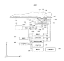
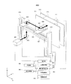
図1は、本発明の実施の形態に係る被検体情報取得装置の実施例1を示すブロック図である。実施例1の被検体情報取得装置1000(以下、「装置1000」と略称する)は、ベッド117、光源101、多関節アーム103、照射部105、音響波受信部166、制御部151、信号処理部165等をベースに構成される。
<Example 1>
FIG. 1 is a block diagram showing Example 1 of the subject information acquiring apparatus according to the embodiment of the present invention. A subject information acquisition apparatus 1000 (hereinafter abbreviated as “
光源101は、波長800nm、パルス幅20nsec、繰り返し周波数10Hz、パルスエネルギー30mJのパルス光を発生するチタンサファイアレーザからなるものであっても良い。多関節アーム103は、水平導波管103a、103e、103i、垂直導波管103c、103g,103k、45度ミラーを内包した関節103b、103d、103f、103h、103jから構成される。導波管103a、103e、103i、103c、103g,103kを伝搬した光は、各関節103b、103d、103f、
103h、103jの前後で伝搬方向を90度変える。
The
The propagation direction is changed by 90 degrees before and after 103h and 103j.
水平導波管103a、関節103b、垂直導波管103cは、それぞれ移動不可能に接続され、かつ、固定されている。関節103d、水平導波管103e、および関節103fは、一体化されているとともに、それぞれの相対的な位置関係が固定されるように接続されている。関節103h、水平導波管103i、および関節103jは、一体化されているとともに、それぞれの相対的な位置関係が固定されるように接続されている。関節103d、103f、103h、および103jは、それぞれ自身に接続されている垂直導波管103c、103g,103kをZ軸と平行な回転軸として水平面内(XY平面内)で回転可能に構成されている。その結果、垂直導波管103kは、水平面内で平行移動或いは回転が可能となっている。なお、これに限られず、装置1000に求められる要求に応じて、関節103d、103f、103h、および103jの一部のみが回転可能に構成されても良い。
The
音響波受信部166は、複数の音響波受信素子109および照射部105が略半球面形状の支持体107により支持されるようにして構成しても良い。音響波受信部166は、支持体107や照射部105と一体となって、音響マッチング剤111を保持可能に構成されるようにしても良い。
The acoustic
照射部105は、光ビームを拡大するための凹レンズ(不図示)を内包しているとともに、垂直導波管103kの終端部に接続可能に構成されている。なお、これに限られず、凹レンズは、照射部105に内包されずに別体として設けられても良い。本実施形態では、多関節アーム103及び照射部105を合わせて照射光学系とする。照射部105は、照射光学系の射出端ともいえる。
The
音響波受信素子109は、支持体107に略半球面形状に沿って複数支持されており、各音響波受信素子109の最も受信感度が高い方向は、略球面形状の曲率中心に向かうものである。そのため、支持体107の略半球面形状の曲率中心とその曲率中心の近傍では、各音響波受信素子109により高感度に光音響波を受信可能な高感度領域が形成されている。音響波受信素子109は、素子サイズ3mm角、検出可能な音響波の中心周波数が2MHzの圧電素子からなるトランスデューサであっても良い。音響波受信素子109は、略半球面形状に500個配列されて設けられても良く、この略半球面形状の半径は、10cmとしても良い。
A plurality of acoustic
支持体107は、照射部105及び音響波受信素子109を支持するものである。支持体107は、略半球面形状に構成されており、音響波受信素子109を略半球面上に沿って支持している。支持体107は、音響波受信素子109及び照射部105と一体となって音響マッチング剤111を保持可能に構成されるようにしても良い。なお、照射部105および音響波受信素子109は単一の支持体107に支持されるだけでなく、別体で構成されていてもよい。
The
支持台113は、支持体107を支えるものであり、XY平面方向に移動可能に構成されている。支持台113は、XY平面方向に移動することにより支持体107を同方向に移動可能に構成されている。支持台113は、XYステージ115上に設置されており、このXYステージ115によりXY平面方向に移動可能に構成されている。XYステージ115は、駆動部153によって移動可能に構成されているものである。XYステージ115は、さらに、位置センサー(不図示)を有している。この位置センサーは、照射部105の位置を検出し、その検出結果である位置情報を後述の位置取得部へ送出するものである。この位置センサーは、XYステージ115がどれくらい駆動されたかに基づいてX座標とY座標に基づいた位置情報を検出するようにしても良い。なお、駆動部153は、
XYステージを駆動するものであるモータードライバーであっても良い。また、駆動部153は、制御部151からの指令に基づいてXYステージを駆動するものであっても良い。
The
A motor driver that drives the XY stage may be used. The
音響マッチング剤111は、保持カップ119と音響波受信素子109との間に設けられるとともに、保持カップ119と音響波受信素子109とを音響結合するものである。しかしこれに限られず、音響マッチング剤111は、保持カップ119を設けない場合は、被検体123と音響波受信素子109とを音響結合するように設けても良い。また、音響マッチング剤111は、被検体123から発生する光音響波を効率よく伝搬できるものであればどのようなものでも良い。音響マッチング剤111は、例えば水や油等である。
The
ベッド117は、例えば人121がうつ伏せになり、開口に乳房等の被検体123を挿入できるように構成されている。
The
保持カップ119は、ベッド117の開口にはめ込むように設けられるようにしても良い。保持カップ119と被検体123との間には音響結合剤である超音波ジェルが設けられ、保持カップ119は、この超音波ジェルにより被検体123と音響結合されている。
The holding
光源101から発せられたパルス光は、多関節アーム103中を伝搬し、照射部105、音響マッチング剤111、保持カップ119、および超音波ジェルを介して被検体123に照射されるものである。音響マッチング剤111、保持カップ119、および超音波ジェルは、パルス光を透過するように構成するのが好ましい。
The pulsed light emitted from the
制御部151は、光源制御部、駆動制御部、収集制御部、および全体を制御するシステム制御部(これらは不図示)を有している。光源制御部は、所望のタイミングでパルス光を発するように光源101を制御する。光源制御部は、例えば、10Hzの繰り返し周波数で光源101がパルス光を発するように光源101を制御するようにしても良い。駆動制御部は、駆動部153を制御し、照射部105に所望の動きを与えるものである。駆動制御部は、例えば、照射部105を螺旋状に移動させるように駆動部153を制御するようにしても良い。駆動制御部は、また、位置取得部155に指令を与え、被検体123にパルス光を照射する瞬間の照射部105の位置情報を上記位置センサーから取得する。本実施例においては、照射部105は、音響波受信素子109と支持体107により一体化されているので、取得された照射部105の位置情報は、音響波受信素子109の電気信号の取得位置情報を兼ねるようにしても良い。なお、位置取得部155は、XYステージの位置を取得するものであっても良い。位置取得部155は、例えばXYステージにエンコーダが設けられており、エンコーダの情報に基づいてXYステージの位置情報を得るようにしても良い。また、これに限られず、駆動部153は、この位置取得部155の機能を含むようにしても良い。
The
そのようにすることで、音響波受信素子109の電気信号の取得位置情報を照射部の位置情報と別のものとして取得する手間を省くことができ、装置100が、被検体情報を取得する際の信号処理にかかる時間を短縮することができる。しかしこれに限られず、この各音響波受信素子109の電気信号の取得位置情報を、照射部の照射位置に基づいて演算により求めるようにしても良い。収集制御部は、被検体123にパルス光を照射した時刻を時刻0usec(マイクロ秒)として、時刻50usecから時刻100usecまでの時間に音響波受信素子109に到達した信号を収集するように電気信号収集部157に指令を与える。時刻0usecから時刻50usecに音響波受信素子109に到達した信号は音響マッチング剤111から発生した信号でありデータとしては意味がないので収集を行わない。時刻50usecから時刻100usecに音響波受信素子109に到達した信号は被検体123からの信号を含んでいるので収集を行う。
By doing so, it is possible to save the trouble of acquiring the acquisition position information of the electrical signal of the acoustic
なお、制御部151は、制御プログラムを有するCPUであっても良い。制御部151は、プログラム動作における基本的なリソースの制御と管理などを行うオペレーティングシステム(OS)を稼働するものであっても良い。
Note that the
また、なお、電気信号収集部157は、音響波受信素子109のそれぞれが生成した電気信号を一括で或いは別々に増幅してデジタルの信号データに変換するものであっても良い。電気信号収集部157は、生成したアナログ信号を増幅する信号増幅部(オペアンプ等)と、アナログ信号をデジタル信号に変換するA/D変換部から構成されても良い。電気信号収集部157は、データが膨大である場合は、FPGAなどの専用IC(Data
Acquisition Systemとも称する)で構成されても良い。
In addition, the electrical
(Acquisition System).
分布記憶部161は、光の断面の光強度プロファイルに関する情報を記憶している。光の断面の光強度プロファイルに関する情報は、以下のような情報としても良い。すなわち、照射部105を光の照射およびその照射に基づく音響波の取得が可能な範囲の中央に置く。そして、照射部105から10cmの位置にスクリーンを配置した場合にそのスクリーンに照射されて形成される光の断面の光強度プロファイルを計測して取得した情報としても良い。音響波の取得が可能な範囲の中央は、例えば保持カップ119の最深部直下である。なお、光源101から射出された光は、照射光学系を通過することで光の断面の光強度プロファイルが変化する。よって、分布記憶部161は、照射光学系の射出端から、この通過後の光が射出された時の光の断面の光強度プロファイルを、全ての光照射位置毎に記憶しているものであっても良い。照射光学系の射出端から、この通過後の光が射出された時の光の断面の光強度プロファイルは、上記の変化を考慮して形成される光の断面の光強度プロファイルであっても良い。
The
変動記憶部163は、照射部105が光を照射する位置ごとの光の断面の光強度プロファイルの変動についての情報を上記変動情報として記憶している。
The
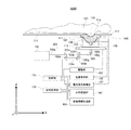
信号処理部165は、まず、照射部105が光の照射を行う位置ごとに、電気信号収集部157により収集された電気信号に対し、UBPアルゴリズムを用いた信号処理を施して形成される3次元の被検体123内の光音響波画像を生成する。照射部105が光の照射を行う位置は、電気信号の取得位置としても良い。信号処理部165は、さらに、以下の情報に基づき光拡散方程式を用いて被検体123内の3次元光量分布(光量分布)情報を生成する。すなわちその情報とは、照射部105の光照射位置ごとに、分布記憶部161に記憶された光の断面の光強度プロファイルに関する情報、および、変動記憶部163に記憶された変動情報である。信号処理部165は、さらに、光音響波画像を3次元光量分布情報で規格化することで、照射部105の光照射位置ごとの被検体123内の光吸収係数分布を得る。信号処理部165は、上記の各工程を照射部105の全光照射位置で実施する。信号処理部165は、上記の処理が終わった後に、得られた光音響波画像データに得られた光吸収係数分布データを重畳することで、被検体123全体の3次元の光音響波画像データおよび光吸収係数分布データを得るものである。
First, the
なお、信号処理部165は、情報処理量が膨大であるため、高性能な演算処理機能を有することが好ましい。また、上記理由から、信号処理部165は、マルチコアCPUなどから構成されることが好ましい。
Note that the
図2は、実施例1の光の断面の光強度プロファイルの回転を示す模式図である。図1に対応する部分には同一の番号を付して、必要にない限り説明を省略する。なお、図2では、ベッド117より上部は省略している。
FIG. 2 is a schematic diagram illustrating the rotation of the light intensity profile of the light cross section of the first embodiment. Parts corresponding to those in FIG. 1 are denoted by the same reference numerals, and description thereof will be omitted unless necessary. In FIG. 2, the upper part from the
図2(a)は、照射部105を所定の中心位置(例えば照射部105の螺旋移動の回転中心)から+X方向に動かした状態を示している。多関節アーム103は、このとき、肘を伸ばした状態と呼ぶことにする。例えば、図2(a)は、多関節アーム103の3つの垂直導波管中に仮想的にスクリーン(図中A、B、Cで表記)を置き、そこに照射された光の断面の光強度プロファイルをベッド側から観察した場合を考えるものである。スクリーンA,B,Cでの光の断面の光強度プロファイルは、それぞれ図中円内に示すようなものである。スクリーンAでの光の断面の光強度プロファイルは、水平導波管103eの断面を対称面として、スクリーンBでの光の断面の光強度プロファイルと鏡像の関係にある。したがって、スクリーンBでの光の断面の光強度プロファイルは、スクリーンAでの光の断面の光強度プロファイルに比べて光の断面の光強度プロファイルが水平導波管103eの断面について反転し、さらに、肘の角度に依存して回転しているものである。さらに、スクリーンBでの光の断面の光強度プロファイルの形状は、水平導波管103iを導波しても保存されたまま(回転しない)であるため、スクリーンCでの光の断面の光強度プロファイルの形状と変わらない。
FIG. 2A shows a state in which the
図2(b)は、照射部105を図2(a)の状態から−X方向に動かした状態を示している。多関節アーム103は、この場合、肘を45度に曲げた状態である。図2(b)においても、図2(a)と同様に、スクリーンA、B、Cにおける光の断面の光強度プロファイルを図中円内に示す。
FIG. 2B shows a state where the
図2(c)は、照射部105を図2(b)の状態からさらに−X方向に動かした状態を示している。この場合、多関節アーム103は、肘を45度を超えて曲げた状態である。図2(c)においても、図2(a)と同様に、スクリーンA、B、Cにおける光の断面の光強度プロファイルを図中円内に示す。図2(a)−図2(c)に示すように、スクリーンCでの光の断面の光強度プロファイル(最終的な光の断面の光強度プロファイル)は、多関節アーム103の肘を曲げていくにしたがって、時計周りに回転するものである。
FIG. 2C shows a state in which the
図3は、実施例1の光の断面の光強度プロファイルの位置ズレを示す模式図である。図1に対応する部分には同一の番号を付して、必要のない限り説明を省略する。図3は、3つの光照射位置で照射された光の断面の光強度プロファイルの位置ズレの様子を説明するものである。なお、図3では、ベッド117より上部は省略している。
FIG. 3 is a schematic diagram illustrating the positional deviation of the light intensity profile of the light cross section of the first embodiment. Parts corresponding to those in FIG. 1 are denoted by the same reference numerals, and description thereof is omitted unless necessary. FIG. 3 is a diagram for explaining the positional shift of the light intensity profile of the cross section of the light irradiated at the three light irradiation positions. In FIG. 3, the upper part from the
図3(a)は、照射部105を所定の中心位置(例えば照射部105の螺旋移動の回転中心)から+X方向に移動させた状態を示す。照射部105は、光源101からの光(光ビーム)を広げる凹レンズ201を有している。凹レンズ201は、光源101からの光をある程度広げて(発散させて)被検体123に照射できるように設けられている。このようにすることにより、より効率的に吸収体からの光音響波を発生させることができるため、より効率的に被検体情報を取得できる。凹レンズ201は、照射部105に内包されるように設けられても良いし、照射部105の外部に別体として設けられても良い。図3(a)において、凹レンズ201には、光源101からの光が右側に入射している。このため、この光は、その重心203が凹レンズ201の曲率に応じて右寄りに屈折されて進んでいく。なお、ここで言う光の重心gは、例えば光ビームの断面の光強度分布からなる2次元の図形D(及びその周辺)の各点rが光強度の密度f(r)を有する場合に、体積要素をdVとして、
oD(g−r)*f(r)dV=0
をみたす点gと定義しても良い。
FIG. 3A shows a state in which the
o D (g−r) * f (r) dV = 0
It may be defined as a point g satisfying.
図3(b)は、照射部105を図3(a)の状態から−X方向に動かした状態を示している。図3(b)では、光の重心207が、凹レンズ201の中心に入射する場合を示しており、このため、この入射光の重心207は屈折しない。したがって、凹レンズ201
から射出された光209はそのまま屈折せずに凹レンズ201により拡大される。
FIG. 3B shows a state where the
The light 209 emitted from the light is not refracted as it is but is expanded by the
図3(c)は、照射部105を図3(b)の状態からさらに−X方向に動かした状態を示している。図3(c)において、光源101からの光が、凹レンズ201の左側に入射している。凹レンズ201は、左側に入射してくる光を発散させるため、光の重心211は、左寄りに屈折される。このようにして、照射部105から射出される光213は、左寄りに屈折するとともに広げられて被検体123に照射される。
FIG. 3C shows a state where the
図2で説明したように、凹レンズ201へ入射する光の重心は、多関節アーム103の肘が曲げられることで回転移動するものである。したがって、凹レンズ201へ入射する光の重心は、多関節アーム103の肘の曲がり具合に応じて回転する。このため、凹レンズ201へ入射する光の重心の位置は、多関節アーム103の肘の曲がり具合に応じた回転により、凹レンズ201の中心位置からズレ得る。そして、照射部105から射出された光の断面の光強度プロファイルは、凹レンズ201へ入射する光の重心の位置と凹レンズ201の中心位置とがズレている場合は、光の重心も含めて回転する。このため、凹レンズ201を通過した後の光の進行方向は、多関節アーム103が図3(a)、図3(b)、図3(c)の順に肘を曲げていくことにより、右寄りから左寄りにシフトする。なお、説明の便宜上、2次元的に動きを表現したが、実際にはこの動きは3次元的に起こるものである。
As described with reference to FIG. 2, the center of gravity of the light incident on the
図4は、実施例1における照射部105の光照射位置を示す模式図である。図4では、走査可能範囲171および照射部105の移動の軌跡173を示している。図4の黒丸は、被検体123にパルス光を照射する瞬間の照射部105の各位置を示すものである。本実施例では、照射部105から被検体123側に10cm離れた位置にスクリーンを配置する。そして、照射部105を512ヶ所の位置(各黒丸の位置)に移動させた際に光を照射して形成されるスクリーン上に現れる光の断面の光強度プロファイルを予め計測する。そして、その計測結果に基づいて各光照射位置(各黒丸の位置)での変動情報を算出している。
FIG. 4 is a schematic diagram illustrating a light irradiation position of the
音響波受信部166は、例えば螺旋状に移動しながら一体化されている照射部105によりパルス光を10Hzの繰り返し周波数で512回照射するように制御されるようにしても良い。この場合、被検体123にパルス光を照射した瞬間の照射部105の位置は、全部で512ヶ所である。
For example, the acoustic
変動記憶部163は、このようにして算出された変動情報を記憶しているものである。
The
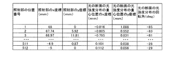
図5は、実施例1の変動記憶部163に記憶された変動情報を示す表である。図5において、左から第1、2、3、4、5、6列目は、それぞれ照射部の位置番号、照射部のx座標、y座標(mm)、光の断面の光強度プロファイルの重心位置のx座標、y座標、(mm)、光の断面の光強度プロファイルの回転角(deg)である。変動記憶部163では、このように各要素を対応づけた形式でそれぞれの情報を格納するようにしても良い。しかし、これに限られず、変動記憶部163では、種々の格納方法を適用可能である。
FIG. 5 is a table showing variation information stored in the
以上説明したように、本実施例においては、分布記憶部161に記憶された光の断面の光強度プロファイルに関する情報および変動記憶部163に記憶された変動情報に基づき、光拡散方程式を用いて被検体123内の3次元光量分布情報を生成する。これにより、照射部105の光照射位置ごとの被検体123内の3次元光量分布をより正確に生成することができる。
As described above, in this embodiment, based on the information on the light intensity profile of the light cross-section stored in the
さらに、同じ光照射位置で得られた光音響波画像を3次元光量分布情報で規格化するこ
とで、照射部105の光照射位置ごとの被検体123内の光吸収係数分布をより正確に得ることが可能となる。
Furthermore, by normalizing the photoacoustic wave image obtained at the same light irradiation position with the three-dimensional light amount distribution information, the light absorption coefficient distribution in the subject 123 for each light irradiation position of the
これらの工程を画像化しようとする領域全体について実施し、最後に、得られた光吸収係数分布を重畳することで、被検体123全体の3次元の光吸収係数分布を精度よく得ることが可能となる。なお、演算の順番はこれに限ったものではなく、まず、被検体123全体の3次元の光音響波画像を取得し、さらに、被検体123全体の3次元光量分布情報を取得し、これらから被検体123全体の3次元の光吸収係数分布を求めるようにしても良い。
By performing these steps for the entire region to be imaged, and finally superimposing the obtained light absorption coefficient distribution, it is possible to obtain the three-dimensional light absorption coefficient distribution of the
なお、保持カップ119は、被検体123を保持することにより、被検体123の形状を保持カップ119の形状(例えばカップ形状)に形成可能なものであっても良い。したがって、装置1000は、上記光照射位置で照射部105が光を照射したときに形成される被検体123内の3次元光量分布を、以下のようにして算出するようにしても良い。すなわち、パルス光が保持カップ119の表面に当たって形成される保持カップの表面での光強度プロファイルに基づいて算出するようにしても良い。
The holding
保持カップ119の形状は、既知である。そのため、パルス光が保持カップ119の表面に当たって形成される光の照射位置毎における保持カップの表面での光強度プロファイルは、以下のように算出可能である。すなわち、照射部105の光の照射位置と、その光の照射位置での上記光の断面の光強度プロファイルと、凹レンズ201の光の拡大率と、保持カップの既知の形状から算出可能である。凹レンズ201の光の拡大率は、あらかじめ計測等により求めておくようにしても良い。光の照射位置での上記光の断面の光強度プロファイルおよび照射部105の光の照射位置も上記より既知である。よって、上記より保持カップ119の表面での光強度プロファイルも既知となる。よって、装置1000は、保持カップ119の表面での光強度プロファイルの基づき演算により3次元光量分布情報を求めるようにしても良い。なお、これに限られず、保持部は、保持カップ119以外にも被検体123を所定の形状に保つことができる種々の形態のものが適用可能である。
The shape of the holding
こうすることにより、3次元光量分布情報の演算量を削減することができるとともに、被検体の特性情報の取得時間を短縮可能である。 By doing so, it is possible to reduce the amount of calculation of the three-dimensional light quantity distribution information, and it is possible to shorten the acquisition time of the characteristic information of the subject.
装置1000は、さらに、このようにして求めた3次元光量分布情報を予めメモリ等に格納しておくようにしても良い。装置1000では、次に3次元光量分布情報を求める際には、このメモリに格納された3次元光量分布情報を読み出して被検体情報取得時に用いるようにすることで、被検体の特性情報の取得時間をさらに短縮可能である。
The
なお、予めメモリに格納しておくための3次元光量分布情報を求める際には、例えば被検体123の換わりに既存のファントムを用いるようにしても良い。また、ファントムを用いる以外に、保持カップ119内に例えば脂肪が満たされていると仮定して、予めメモリに格納しておくための3次元光量分布情報を求めるようにしても良い。このようにすることで、予めメモリに格納しておくための3次元光量分布情報を容易に取得可能である。なお、上記のことは、保持部(例えば保持カップ119)を有する後述の他の実施例においても同様である。
When obtaining the three-dimensional light amount distribution information to be stored in the memory in advance, an existing phantom may be used instead of the subject 123, for example. In addition to using a phantom, it is also possible to obtain three-dimensional light amount distribution information for storing in advance in a memory, assuming that the holding
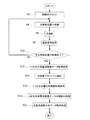
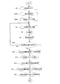
図6Aは、実施例1の装置1000の機能の一例を示すフローチャートである。フローは装置1000に給電されてスタートする。ステップS2で、被検体123がベッド117に設けられた開口に挿入される。そして、被検体123が保持カップ119に保持されることにより装置1000にセットされ、ステップS4に移行する。ステップS4で、被検体123に光を照射する位置まで照射部105が移動され、ステップS6に移行する。
ステップS6で、その移動された後の位置で照射部105により光が照射され、ステップS8に移行する。ステップS8で、その光の照射によって被検体123から伝播してきた音響波が音響波受信部166により受信され、その音響波が電気信号に変換されて電気信号収集部157により取得され、ステップS10に移行する。ステップS10で、あらかじめ定められている光照射位置全てにおいて、電気信号が取得されたか否かが判断される。そして、512箇所の全ての光照射位置で電気信号が取得されたと判断されたときは、ステップ12に移行し、全ての光照射位置で電気信号が取得されていないときは、再びステップS4に移行する。そして、ステップS10で、512箇所の全ての光照射位置で電気信号が取得されたと判断されるまでステップS4からステップS8の処理が繰り返し実行される。
FIG. 6A is a flowchart illustrating an example of functions of the
In step S6, light is irradiated by the
ステップS12で、取得された電気信号に基づいて信号処理部165により画像再構成されることで、3次元光音響波画像データが取得される。この場合、UBPアルゴリズムを用いた画像再構成処理により光照射位置毎の3次元ボクセルデータがそれぞれ形成される。そして、それらの3次元ボクセルデータが結合される。そして、被検体123全体を含む3次元光音響波画像データが取得され、ステップS14に移行する。ステップS14で、分布記憶部161から光照射位置毎の光の断面の光強度プロファイルに関する情報が読み出され、ステップS16に移行する。ステップS16で、信号処理部365により、光照射位置ごとに、読み出された光の断面の光強度プロファイルに関する情報に基づき光拡散方程式を用いて被検体123内の3次元光量分布情報が取得される。そして、ステップS18に移行する。ステップS18で、取得された3次元光量分布情報に基づいて信号処理部165により3次元光音響波画像データが規格化(補正)されることで規格化後の3次元光音響波画像データが取得され、ステップS20に移行する。ステップS20で、信号処理部により、この規格化後の3次元光音響波画像データに3次元光吸収係数分布が重畳されることで、被検体123の3次元光吸収係数分布データが取得され、フローを終了する。なお、この場合は、必ずしも変動記憶部163を用いる必要はない。
In step S12, image reconstruction is performed by the
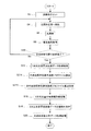
図6Bは、実施例1の装置1000の機能の他の一例を示すフローチャートである。図6Aにとの違いは、以下のようなものである。すなわち、分布記憶部161に光照射位置の内、中央一か所のみの、光の断面の光強度プロファイルが格納されていること。そして、その中央の光の断面の光強度プロファイルからのズレについての情報を変動記憶部163から適宜読み出すこと。そして、その中央の光の断面の光強度プロファイルに、その読み出したズレ情報を加味することで、他の光照射位置での光の断面の光強度プロファイルが取得されることである。以上に対応する処理は、ステップS140からステップS142までの処理であり、それ以外は図6Aにおけるフローと同様であるため説明を省略する。
FIG. 6B is a flowchart illustrating another example of the functions of the
すなわち、図6Aでの処理と同様のステップS2からステップS12での処理が終了すると、ステップS140へ移行する。ステップS140で、分布記憶部161から中央の光照射位置での光の断面の光強度プロファイルが読み出され、ステップS141へ移行する。ステップS141で、変動記憶部163から光照射位置に対応した変動情報が光照射位置毎に読み出され、ステップS142へ移行する。ステップS142で、信号処理部165により、光照射位置毎に、中央の光照射位置での光の断面の光強度プロファイルおよび中央以外の光照射位置に対応する変動情報に基づいて、その中央以外の光照射位置での光の断面の光強度プロファイルが算出される。この算出処理が全光照射位置について実行され、ステップS16へ移行する。そして、図6Aでの処理と同様のステップS16からステップS20での処理が実行され、フローを終了する。
That is, when the processing from step S2 to step S12 similar to the processing in FIG. 6A is completed, the process proceeds to step S140. In step S140, the light intensity profile of the light cross section at the central light irradiation position is read from the
なお、これに限られず、分布記憶部161では、中央の光照射位置一か所からのズレでなくとも、例えば2箇所からのズレや、中央でなく他の光照射位置における光の断面の光
強度プロファイルからのズレ情報を記憶するようにしても良い。
Note that the
<実施例2>
図7は、本発明の実施の形態に係る被検体情報取得装置の実施例2を示すブロック図であり、実施例1と共通の構成については同一の番号を付して説明を省略する。本実施例の被検体情報取得装置2000(以下「装置2000」と略称する)は、被検体123に光を照射するためのすべての光照射位置での変動情報を記憶せず、代表的な複数の光照射位置での変動情報のみを記憶する。そして、装置2000は、その他の光照射位置での変動情報は補間により生成するものである。装置2000は、この点で実施例1の装置1000と異なる。これを実現するために、装置2000は、変動記憶部263および補間部259を有するものである。
<Example 2>
FIG. 7 is a block diagram showing Example 2 of the subject information acquiring apparatus according to the embodiment of the present invention, and the same components as those in Example 1 are denoted by the same reference numerals and description thereof is omitted. The subject information acquisition apparatus 2000 (hereinafter abbreviated as “
変動記憶部263は、代表的な17箇所の光照射位置での変動情報を記憶している。
The
図8は、実施例2における光の断面の光強度プロファイルの変化を示す図である。図8は、実際に測定した光の断面の光強度プロファイルの変化を示すものであり、位置(X座標、Y座標)=(−68,0)、(−34,0)、(0,0)、(34,0)、(68,0)、(0、−68)、(0、−34)、(0,34)、(0,68)、(−48,−48)、(−24,−24)、(24,24)、(48,48)、(−48,48)、(−24,24)、(−24,24)、(−48,48)(単位:mm)で照射部105が光を照射した場合における光の断面の光強度プロファイルのそれぞれを示すものである。図8からわかるように、光の断面の光強度プロファイルは、座標に応じてその形状が回転している。光の断面の光強度プロファイルは、多関節アーム103の肘の曲げ具合によって光の断面の光強度プロファイルが回転していることがわかる。図8において、最も+X側にある光の断面の光強度プロファイルの図は、肘を最も伸ばした状態のものであり、最も−X側にある光の断面の光強度プロファイルの図は、左端は肘を最も曲げた状態のものである。図8において、光の断面の光強度プロファイルは、+X側から−X側に向かうにつれて、すなわち、多関節アーム103の肘を曲げていくにつれて、時計回りに回転するものである。このことは、図2で説明したとおりの結果である。
FIG. 8 is a diagram illustrating a change in the light intensity profile of the light cross section in the second embodiment. FIG. 8 shows the change of the light intensity profile of the cross section of the light actually measured. The position (X coordinate, Y coordinate) = (− 68,0), (−34,0), (0,0). ), (34,0), (68,0), (0, −68), (0, −34), (0,34), (0,68), (−48, −48), (− 24, -24), (24, 24), (48, 48), (-48, 48), (-24, 24), (-24, 24), (-48, 48) (unit: mm) FIG. 4 shows each of the light intensity profiles of the cross section of the light when the
図9は、実施例2における射出される光の変動量の計算結果を示す表である。左の列から順に、照射部105のx座標(mm)、照射部105のy座標(mm)、光の断面の光強度プロファイルの重心位置のx座標、光の断面の光強度プロファイルの重心位置のy座標(mm)、光の断面の光強度プロファイルの回転角(deg)である。
FIG. 9 is a table showing the calculation results of the amount of fluctuation of the emitted light in the second embodiment. In order from the left column, the x coordinate (mm) of the
変動記憶部263は、この図9に示した表を変動情報として記憶しているものである。
The
音響波受信部166は、第1の実施例と同様に、螺旋状に移動しながら一体化されている照射部105によりパルス光を10Hzの繰り返し周波数で512回照射されるように制御するようにしても良い。すなわち、実際に被検体123にパルス光を照射した瞬間の照射部105の位置は、全部で512ヶ所であるようにしても良い。
Similarly to the first embodiment, the acoustic
補間部259は、変動記憶部263に記憶されており、図9に示されている17ヶ所の代表的な光照射位置での変動情報から実際の上記512ヶ所の光照射位置での各変動情報をスプライン補間により生成するようにしても良い。しかしこれに限られず、実際の512ヶ所の光照射位置での各変動情報の生成に用いる補間方法は、種々の補間方法が適用できる。なお、補間部259は、信号処理部165に比べると情報処理量が小さい。よって、信号処理部165は、補間部259の機能を有するように構成しても良い。この場合、補間部259は、信号処理部165に含まれるものであって、マルチコアCPUで構成されても良い。
The
被検体情報の一つである光音響波画像の取得方法については、第1の実施例と同様の方法であっても良い。本実施例において、変動記憶部263では、予め代表的な17箇所の光照射位置での変動情報を格納しておくだけで良いので、容易に被検体情報の取得が可能である。
A method for obtaining a photoacoustic wave image that is one of the object information may be the same as that in the first embodiment. In the present embodiment, the
図10は、実施例2の装置2000の機能を示すフローチャートである。ステップS2からステップS12までの処理およびステップS16からステップS20までの処理は、図6Aまたは図6Bのフローと同様であるため、説明を省略する。すなわち、図6Aでの処理と同様のステップS2からS12の処理が終了するとステップS214へ移行する。ステップS214で、分布記憶部161から代表的な17箇所の光照射位置での光の断面の光強度プロファイルが読み出され、ステップS215へ移行する。
FIG. 10 is a flowchart illustrating functions of the
ステップS215で、495箇所の非代表光照射位置(代表的な17箇所の光照射位置以外の光照射位置)での光の断面の光強度プロファイルが補間部259により算出される。この場合、代表的な17箇所の光照射位置は、螺旋状にほぼ等間隔で設けられているようにしても良い。そして、非代表光照射位置が、この代表的な光照射位置の一つ一つの間に略29箇所ずつ等間隔に配置されているようにしても良い。この場合に、補間部259により、その略29箇所の非代表光照射位置を挟むとともに上記螺旋形状に沿って配置される2箇所の代表的な光照射位置に対してスプライン補間(内挿補間)が行われる。そうされることで、螺旋状に連続して配置された約29箇所の非代表光照射位置での各光強度プロファイルが算出される。他の螺旋状に連続して配置された略29箇所の非代表光照射位置での各光強度プロファイルも同様にして算出される。このようにして、代表および非代表の光照射位置での光の断面の光強度プロファイルが取得され、ステップ16へ移行し、その後は図6A、Bの処理と同様である。なお、この場合には、必ずしも変動記憶部263は用いる必要はない。
In step S215, the light intensity profile of the cross section of the light at 495 non-representative light irradiation positions (light irradiation positions other than the typical 17 light irradiation positions) is calculated by the
なお、他の例として、分布記憶部161に光照射位置の内、中央一か所のみの、光の断面の光強度プロファイルが格納されているようにしても良い。この場合、ステップS214では、その中央一か所のみの、光の断面の光強度プロファイルが読み出され、ステップS215へ移行するようにしても良い。ステップS215では、補間部259により、その中央の光の断面の光強度プロファイルからのズレ情報が変動記憶部163から適宜読み出される。そして、その中央の光の断面の光強度プロファイルに、その読み出されたズレ情報を加味する。そうして他の代表的な16箇所の光照射位置(17箇所の代表光照射位置のうち1箇所は上記中央の光照射位置とする)での光の断面の光強度プロファイルが取得されるようにしても良い。その後は、上記と同様である。
As another example, the
<実施例3>
図11は、本発明の実施の形態に係る被検体情報取得装置の実施例3を示すブロック図であり、図1または図7に対応する部分には同一の番号を付して、必要のない限り説明を省略する。本実施例の被検体情報取得装置3000(以下「装置3000」と略称する)は、超音波エコーやMRIなど他のイメージング装置を用いて生成した画像や、触診などによって関心領域が予め分かっている場合を想定するものである。装置3000は、関心領域設定部を設けた点で実施例2の装置2000と異なるものである。装置3000は、関心領域設定部271および制御部273を有する。
<Example 3>
FIG. 11 is a block diagram showing Example 3 of the subject information acquiring apparatus according to the embodiment of the present invention, and parts corresponding to FIG. 1 or FIG. As long as the description is omitted. The subject information acquisition apparatus 3000 (hereinafter simply referred to as “
関心領域設定部271は、被検体315(或いはその周辺も含む)に対して画像再構成を行う領域である関心領域を設定するものである。装置3000は、モニタ(不図示)を有しており、このモニタは、操作者が関心領域を指定可能に構成されている。関心領域設定部271では、このモニタからの指定結果に基づいて関心領域を設定するものである。
The region-of-
制御部273は、駆動制御部を有する。駆動制御部は、関心領域設定部271により設定された関心領域に基づいて、照射部105の移動範囲、移動および光の照射の方法を決定するようにしても良い。駆動制御部は、さらに、この決定結果である信号を駆動部153に入力する。駆動部153は、この入力結果である信号に基づいて照射部105を上記決定された移動範囲、移動方法、光の照射方法で駆動させる。
The
図12は、実施例3の被検体情報取得装置における関心領域の設定を示す模式図である。図12では、走査可能範囲171および関心領域275に基づいて決定された照射部105の移動の軌跡277が示されている。関心領域275の設定箇所は、操作者が被検体123の形状等を見て操作者が決定するようにしても良い。関心領域275の設定箇所は、この場合、被検体123の形状等に依存する。照射部105は、この関心領域275を画像化できるように光の照射を行うため、光の照射位置もこの関心領域275に依存したものとなり、この関心領域275に依存した移動パターンで移動するようにしても良い。すなわち、照射部105の駆動および関心領域設定部271の処理は、被検体123の形状等に依存して決定されるものである。このため、照射部105の駆動および関心領域設定部271の処理は、被検体123の形状等の個体間のばらつき等に応じて無限のパターンが存在する。なお、この関心領域設定部271は、関心領域275を被検体123に対して略立方体形状、すなわち、図12において、XY平面への関心領域275の射影が略正方形となるように設定するようにしても良い。
FIG. 12 is a schematic diagram illustrating setting of a region of interest in the subject information acquisition apparatus according to the third embodiment. FIG. 12 shows a
このような場合、変動記憶部263では、すべての照射部105の光照射位置における変動情報を予め記憶しておくよりも、第2の実施例と同様に、代表的な複数の光照射位置での変動情報のみを記憶しておくようにするほうが好ましい。補間部259では、変動記憶部263により記憶されている変動情報を用いて実際の照射部105の光照射位置における変動情報を補間により生成するようにしても良い。
In such a case, in the
このようにすることで、上記無限のパターンに対して容易に光音響測定が可能となる。 By doing in this way, a photoacoustic measurement can be easily performed with respect to the infinite pattern.
なお、関心領域設定部271は、モニタを介して操作者からの指令を入力するものである。しかし、これに限られず、装置3000により自動的に被検体123の形状等を取得して、その取得結果に基づいて関心領域設定部271に指令を出力するようにしても良い。例えば、装置3000では、CCDイメージセンサ等の固体撮像装置を用いて被検体123の形状等を撮像するとともに、この撮像結果に基づいた信号を上記指令として関心領域設定部271に送出するようにしても良い。
The region-of-
図13は、実施例3の装置3000の機能を示すフローチャートである。ステップS303及びステップS305以外は図6Aのフローと同様であるため、説明を省略する。すなわち、図6Aでの処理と同様のステップS2が終了するとステップS303へ移行する。ステップS303で、関心領域設定部271により被検体315(或いはその周辺も含む)に対して関心領域275が設定される。この場合、装置3000の操作者が手入力により付属のモニタ(不図示)を介して関心領域設定部271が制御されることで関心領域275が設定され、ステップS305へ移行する。
FIG. 13 is a flowchart illustrating functions of the
ステップS305で、上記付属のモニタ上での操作者の手入力により、光照射パターンが設定される。この光照射パターンは、関心領域275全域を画像再構成するに足りるものであることが好ましい。この場合、この光照射パターンとして、照射部105の移動すべき軌跡277が、走査可能範囲171および関心領域275に基づいて決定される。すなわち、図10に示すように、照射部105の螺旋移動の軌跡の中心が関心領域275の略中心と一致し、かつ、螺旋移動の軌跡の大半が図10の関心領域275のXY平面への
射影の内部に包含されるように設定される。このようにすることで、関心領域275の全範囲が画像再構成し易くなるからである。そして、以後の処理は図6Aのものと同様である。
In step S305, a light irradiation pattern is set by the operator's manual input on the attached monitor. This light irradiation pattern is preferably sufficient to reconstruct the entire region of
<実施例4>
図14は、本発明の実施の形態に係る被検体情報取得装置の実施例4を示すブロック図である。本実施例の被検体情報取得装置4000(以下「装置4000」と略称する)は、光伝送部として、空間伝送系を採用可能である。装置4000は、光源301、空間伝送系であるプリズム303、305、307、照射部309、保持板311,313、音響波受信素子317、Z軸ステージ319、X軸ステージ321、および支持部323、325等をベースに構成される。
<Example 4>
FIG. 14 is a block diagram showing Example 4 of the subject information acquiring apparatus according to the embodiment of the present invention. The subject information acquisition apparatus 4000 (hereinafter abbreviated as “
プリズム303、305、307は、光源301から発せられたパルス光の進行方向を90度曲げるものである。Z軸ステージ319は、X軸ステージを上下方向(Z方向)に移動させることが可能に構成される。保持板311,313は、一対のプレートからなり、被検体(例えば乳房)315を保持可能に構成される。音響波受信素子317は、ピエゾ素子等(なお、これに限られず音響波を受信可能な素子であればどのようなものでも良い)を2次元上に配列して構成されるようにしても良い。また、探触子の少なくとも一部が音響波受信素子317であっても良い。音響波受信素子317は、X軸ステージ321およびZ軸ステージ319によって2次元方向(XZ平面方向)に移動可能としても良いし、照射部309と同期して移動するようにしても良いし、照射部309の動きに追従して移動するようにしても良い。しかしこれに限られず、音響波受信素子317は、移動させずに最も受信感度の高い方向(指向性)の向きを変えるようにしても良いし、位置を固定するとともに2次元状に複数配列するようにしても良い。支持部323は、光源301からのパルス光を遮らないように、パルス光が貫通できる穴を設けられて構成されているようにしても良い。支持部325は、プリズム307および照射部309を支持するものであり、X軸ステージ321により水平方向に移動可能に構成される。
The
制御部351は、光源制御部、駆動制御部、収集制御部、および全体を制御するシステム制御部(これらは不図示)を有している。光源制御部は、所望のタイミングでパルス光を発するように光源301を制御する。光源制御部は、パルス光の繰り返し周波数が10Hzになるように光源301を制御する。駆動制御部は、駆動部353が照射部309に所望の動きを与えるように駆動部を制御するものである。駆動制御部は、また、位置取得部355に指令を与え、位置取得部355は、この指令に基づいてX軸ステージ321、Z軸ステージ319の位置情報を取得する。この位置情報は、照射部309の光照射位置についての情報に相当するものであっても良い。位置取得部355では、X軸ステージ321、Z軸ステージ319がどれぐらい駆動されたかの情報に基づき位置情報を取得するようにしても良い。または、あらかじめ定められている所定の光照射位置情報をメモリ等で記憶しておき、光を照射する時刻に基づいて、記憶されている光照射位置情報を参照することにより位置情報を取得するようにしても良い。
The
収集制御部は、被検体315にパルス光を照射した時刻を時刻0usecとして、時刻0usecから時刻50usecまでの時間に音響波受信素子317に到達した信号を収集するように電気信号収集部357に指令を与える。この時刻0usecから時刻50usecまでの時間に取得される音響波は、保持板311および被検体315の表面から被検体315内深度70mm強までの各位置で発生したものである。
The collection control unit instructs the electrical
分布記憶部361は、光の断面の光強度プロファイルに関する情報を記憶している。この光強度分布に関する情報は、以下のようにして取得されたデータであっても良い。すなわち、照射部309を移動が可能な範囲の中央に置く。そして、保持板311の被検体3
15が位置する側にスクリーンを配置した場合において、照射部309により照射された光がこのスクリーン上に形成される光の断面の光強度プロファイルを計測する。その計測結果に基づいて取得されたデジタルまたはアナログのデータを光強度分布に関する情報としても良い。
The
When the screen is arranged on the side where 15 is located, the light intensity profile of the cross section of the light formed on the screen by the light irradiated by the
変動記憶部363は、照射部309の光照射位置ごとの変動情報をそれぞれ記憶している。この変動情報は、例えば、走査時において光の伝搬距離が異なることに起因する光の断面の光強度プロファイルの拡がりを含むものであっても良い。或いは、各プリズム303、305、307の取り付け誤差に起因する光の断面の光強度プロファイルの位置ズレ量についての情報を含むものであっても良い。
The
信号処理部365は、照射部309の光照射位置、すなわち、音響波取得位置ごとに、電気信号収集部357により収集された光音響波に基づく電気信号からUBPアルゴリズムを用いて3次元の被検体315内の光音響波画像(被検体情報の一つ)を生成する。そして、信号処理部365は、照射部309の光照射位置ごとに、以下の情報に基づき光拡散方程式を用いて被検体315内の3次元光量分布情報を生成する。その情報は、分布記憶部361に記憶された光の断面の光強度プロファイルに関する情報、および、変動記憶部363に記憶された変動情報である。この3次元光量分布情報は、被検体情報の一つである。信号処理部365は、さらに、生成した光音響波画像を3次元光量分布情報で規格化することで、照射部309の光照射位置ごとの被検体315内の光吸収係数分布を得る。信号処理部365は、これらの工程を照射部309の走査範囲全体で実施し、最後に、得られた光音響波画像、光吸収係数分布を重畳することで、被検体315の全体の3次元の光音響波画像および光吸収係数分布を得る。
The
その結果、被検体315の全体の3次元の光吸収係数分布を精度よく得ることが可能となる。 As a result, the entire three-dimensional light absorption coefficient distribution of the subject 315 can be obtained with high accuracy.
<実施例5>
図15は、本発明の実施の形態に係る被検体情報取得装置の実施例5を示すブロック図であり、図1、6、または9に対応する部分には同一の番号を付して、必要のない限り説明を省略する。本実施例の被検体情報取得装置5000(以下、「装置5000」と略称する)は、照射部105の光照射位置と変動情報との関係式を予め取得しておく。その関係式を用いて変動情報を生成するという点で、予め求めた全ての照射部の光照射位置での変動情報を記憶しておくように構成された実施例1の装置1000と異なるものである。装置5000は、変動情報生成部401を有しており、変動情報生成部401は、照射部105の光照射位置(座標)と変動情報との関係式を有している。変動情報生成部401は、位置取得部155で得られた照射部105の光照射位置についての情報に基づき、変動情報を生成するものである。
<Example 5>
FIG. 15 is a block diagram showing Example 5 of the subject information acquiring apparatus according to the embodiment of the present invention, and parts corresponding to those in FIG. The description is omitted unless otherwise noted. The subject information acquisition apparatus 5000 (hereinafter, simply referred to as “
以下に照射部105の位置と変動情報との関係式について説明する。
Hereinafter, a relational expression between the position of the
図2を用いて説明したように、垂直導波管103c内の光の断面の光強度プロファイルは、水平導波管103eの断面を対称面として垂直導波管103g内の光の断面の光強度プロファイルと鏡像の関係にある。上記対称面のXY平面における傾きは、水平導波管103aのXY平面への射影の長手方向と、水平導波管103eのXY平面への射影の長手方向との間の角度によって決まるものである。多関節アーム103の各腕の長さは、それぞれ決まっている。このため、上記対称面のXY平面における傾きは、照射部105の位置が決まれば一意に決まる。よって、光の断面の光強度プロファイルの回転角は、照射部105の光照射位置の関数として定義できる。また、光の断面の光強度プロファイルの重心の位置ズレ量は、以下のようにして取得可能である。まず、照射部105が有する凹レ
ンズの光軸と実際の射出光の重心とのズレ量と、照射部105の光の拡大率とを実験的に求める。その上で、光の断面の光強度プロファイルの回転角が取得できれば、所定の量に基づき算出可能である。所定の量とは、光の拡大率、実際の射出光の重心とのズレ量、および光の断面の光強度プロファイルの回転角である。したがって、光の断面の光強度プロファイルの位置ズレ量および光の断面の光強度プロファイルの回転角は、照射部105の光照射位置の関数として定義できる。変動情報生成部401は、この光照射位置の関数を関係式として保持しておくようにするとともに、照射部105の光照射位置情報を入力するようにし、この関係式および光照射位置情報とに基づき変動情報を生成するようにしても良い。なお、変動情報生成部401は、信号処理部165に比べると情報処理量は小さい。よって、信号処理部165は、変動情報生成部401の機能を有するように構成しても良い。
As described with reference to FIG. 2, the light intensity profile of the cross section of the light in the
このようにすることで、被検体123全体の3次元の光吸収係数分布を精度よく得ることが可能となる。
In this way, it is possible to obtain a three-dimensional light absorption coefficient distribution of the
図16は、実施例5の装置5000の機能を示すフローチャートである。ステップS514およびステップS515以外の処理は、図6Aのフローと同様であるため、説明を省略する。すなわち、図6Aでの処理と同様のステップS2からS12の処理が終了するとステップS514へ移行する。ステップS514で、分布記憶部161から光源101から射出された光の断面の光強度プロファイルが読み出され、ステップS515へ移行する。
FIG. 16 is a flowchart illustrating functions of the
ステップS515で、照射部105が光を照射した位置が光照射位置情報として変動情報生成部401に入力される。そして、読み出された光源101から射出された光の断面の光強度プロファイルが変動情報生成部401に入力される。そして、この入力された光照射位置情報および上記光強度プロファイルを上記関係式のパラメータとしてこの関係式の演算処理が変動情報生成部401により行われる。そして、この演算結果が照射部105から射出された光の断面の光強度プロファイルとして取得される。以上の処理が全ての光照射位置について実行され、ステップS16へ移行する。その後の処理は図6Aの場合と同様である。
In step S515, the position where the
<その他の実施形態>
記憶装置に記録されたプログラムを読み込み実行することで前述した実施形態の機能を実現するシステムや装置のコンピュータ(又はCPU、MPU等のデバイス)によっても、本発明を実施することができる。また、例えば、記憶装置に記録されたプログラムを読み込み実行することで前述した実施形態の機能を実現するシステムや装置のコンピュータによって実行されるステップからなる方法によっても、本発明を実施することができる。この目的のために、上記プログラムは、例えば、ネットワークを通じて、又は、上記記憶装置となり得る様々なタイプの記録媒体(つまり、非一時的にデータを保持するコンピュータ読取可能な記録媒体)から、上記コンピュータに提供される。したがって、上記コンピュータ、上記方法、上記プログラム、上記プログラムを非一時的に保持するコンピュータ読取可能な記録媒体は、いずれも本発明の範疇に含まれる。上記コンピュータは、CPU、MPU等のデバイスを含むものである。上記プログラムは、プログラムコード、プログラムプロダクトを含むものである。
<Other embodiments>
The present invention can also be implemented by a computer (or a device such as a CPU or MPU) of a system or apparatus that implements the functions of the above-described embodiments by reading and executing a program recorded in a storage device. For example, the present invention can be implemented by a method including steps executed by a computer of a system or apparatus that implements the functions of the above-described embodiments by reading and executing a program recorded in a storage device. . For this purpose, the program is stored in the computer from, for example, various types of recording media that can serve as the storage device (ie, computer-readable recording media that holds data non-temporarily). Provided to. Accordingly, the computer, the method, the program, and the computer-readable recording medium that holds the program non-temporarily are included in the scope of the present invention. The computer includes devices such as a CPU and MPU. The program includes a program code and a program product.
101 光源、103 多関節アーム、105 照射部、161 分布記憶部、165 信号処理部、166 音響波受信部
DESCRIPTION OF
Claims (12)
前記光源からの光を被検体まで導く照射光学系と、
前記照射光学系を移動させることにより前記照射光学系に複数の照射位置で光を射出させる移動部と、
前記照射光学系から射出された光が前記被検体に照射されることにより発生する音響波を前記照射位置毎に受信して電気信号を出力する音響波受信部と、
前記照射位置で射出された光の断面の光強度プロファイルが前記照射位置毎に予め記憶された記憶部と、
前記照射位置の情報と前記記憶部から読み出した前記照射位置で射出された光の断面の光強度プロファイルとに基づいて、前記光が前記被検体に照射されて形成される前記被検体内の光量分布を取得するとともに、取得した前記光量分布と前記照射位置毎に出力された前記電気信号に基づいて前記被検体の特性情報を取得する取得部と、
を有する被検体情報取得装置。 A light source;
An irradiation optical system for guiding light from the light source to the subject;
A moving unit that causes the irradiation optical system to emit light at a plurality of irradiation positions by moving the irradiation optical system;
An acoustic wave receiving unit that receives an acoustic wave generated by irradiating the subject with light emitted from the irradiation optical system and outputs an electrical signal for each irradiation position;
A storage unit in which a light intensity profile of a cross section of light emitted at the irradiation position is stored in advance for each irradiation position;
Based on the information on the irradiation position and the light intensity profile of the cross section of the light emitted at the irradiation position read from the storage unit, the amount of light in the object formed by irradiating the object with the light An acquisition unit that acquires distribution and acquires characteristic information of the subject based on the acquired light amount distribution and the electrical signal output for each irradiation position;
A subject information acquisition apparatus having:
前記光源からの光を被検体まで導く照射光学系と、
前記照射光学系を移動させることにより前記照射光学系に複数の照射位置で光を射出させる移動部と、
前記照射光学系から射出された光が前記被検体に照射されることにより発生する音響波を前記照射位置毎に受信して電気信号を出力する音響波受信部と、
前記光源から射出される光の断面の光強度プロファイルが予め記憶された記憶部と、
前記照射位置の情報と前記記憶部から読み出した前記光源から射出される光の断面の光強度プロファイルとを用いて所定の関係式に基づいて前記照射位置で射出された光の断面の光強度プロファイルを取得し、取得した前記照射位置で射出された光の断面の光強度プロファイルに基づいて前記照射位置毎の前記光が前記被検体に照射されて形成される前記被検体内の光量分布を取得するとともに、取得した前記光量分布と前記照射位置毎に出力された前記電気信号とに基づいて前記被検体の特性情報を取得する取得部と、
を有する被検体情報取得装置。 A light source;
An irradiation optical system for guiding light from the light source to the subject;
A moving unit that causes the irradiation optical system to emit light at a plurality of irradiation positions by moving the irradiation optical system;
An acoustic wave receiving unit that receives an acoustic wave generated by irradiating the subject with light emitted from the irradiation optical system and outputs an electrical signal for each irradiation position;
A storage unit in which a light intensity profile of a cross section of light emitted from the light source is stored in advance;
The light intensity profile of the cross section of the light emitted at the irradiation position based on a predetermined relational expression using the information on the irradiation position and the light intensity profile of the cross section of the light emitted from the light source read from the storage unit And obtaining a light amount distribution in the subject formed by irradiating the subject with the light at each irradiation position based on a light intensity profile of a cross section of the light emitted at the obtained irradiation position. And an acquisition unit for acquiring characteristic information of the subject based on the acquired light amount distribution and the electrical signal output for each irradiation position;
A subject information acquisition apparatus having:
前記複数の関節のうち少なくとも一部の関節は当該一部の関節に接続されている前記導波管を軸として回転可能に構成されている請求項1から6のいずれか1項に記載の被検体
情報取得装置。 The irradiation optical system is connected by a plurality of waveguides configured to be hollow inside so that light can be propagated, and a plurality of joints having a mirror that bends the light propagation direction while connecting the plurality of waveguides. Is formed,
7. The covered body according to claim 1, wherein at least some of the plurality of joints are configured to be rotatable about the waveguide connected to the some joints. Sample information acquisition device.
前記所定の照射位置で射出された前記光の断面の光強度プロファイルは前記照射光学系の形状に応じて定まるものである請求項1から7のいずれか1項に記載の被検体情報取得装置。 The irradiation optical system has a shape determined according to the irradiation position,
The object information acquiring apparatus according to claim 1, wherein a light intensity profile of a cross section of the light emitted at the predetermined irradiation position is determined according to a shape of the irradiation optical system.
Priority Applications (3)
| Application Number | Priority Date | Filing Date | Title |
|---|---|---|---|
| JP2015032153A JP2016152879A (en) | 2015-02-20 | 2015-02-20 | Subject information acquisition apparatus |
| US15/546,075 US20180011061A1 (en) | 2015-02-20 | 2016-02-02 | Object information acquiring apparatus and signal processing method |
| PCT/JP2016/000735 WO2016132720A1 (en) | 2015-02-20 | 2016-02-12 | Object information acquiring apparatus and signal processing method |
Applications Claiming Priority (1)
| Application Number | Priority Date | Filing Date | Title |
|---|---|---|---|
| JP2015032153A JP2016152879A (en) | 2015-02-20 | 2015-02-20 | Subject information acquisition apparatus |
Publications (2)
| Publication Number | Publication Date |
|---|---|
| JP2016152879A true JP2016152879A (en) | 2016-08-25 |
| JP2016152879A5 JP2016152879A5 (en) | 2018-04-05 |
Family
ID=55456856
Family Applications (1)
| Application Number | Title | Priority Date | Filing Date |
|---|---|---|---|
| JP2015032153A Pending JP2016152879A (en) | 2015-02-20 | 2015-02-20 | Subject information acquisition apparatus |
Country Status (3)
| Country | Link |
|---|---|
| US (1) | US20180011061A1 (en) |
| JP (1) | JP2016152879A (en) |
| WO (1) | WO2016132720A1 (en) |
Families Citing this family (2)
| Publication number | Priority date | Publication date | Assignee | Title |
|---|---|---|---|---|
| WO2016031213A1 (en) * | 2014-08-26 | 2016-03-03 | Canon Kabushiki Kaisha | Object information acquiring apparatus and processing method |
| US20230033766A1 (en) * | 2021-07-28 | 2023-02-02 | Seno Medical Instruments, Inc. | Optoacoustic probe |
Citations (5)
| Publication number | Priority date | Publication date | Assignee | Title |
|---|---|---|---|---|
| JP2010017427A (en) * | 2008-07-11 | 2010-01-28 | Canon Inc | Optoacoustic measuring instrument |
| JP2011206192A (en) * | 2010-03-29 | 2011-10-20 | Canon Inc | Photoacoustic imaging apparatus, photoacoustic imaging method, and program for executing the photoacoustic imaging method |
| JP2013099566A (en) * | 2013-01-22 | 2013-05-23 | Canon Inc | Photoacoustic measuring device |
| JP2013128760A (en) * | 2011-11-22 | 2013-07-04 | Fujifilm Corp | Photoacoustic image generation device and photoacoustic image generation method |
| JP2013188489A (en) * | 2013-04-30 | 2013-09-26 | Canon Inc | Subject information processing apparatus and method for operating the same |
Family Cites Families (2)
| Publication number | Priority date | Publication date | Assignee | Title |
|---|---|---|---|---|
| JP5693043B2 (en) | 2010-04-28 | 2015-04-01 | キヤノン株式会社 | Subject information acquisition apparatus and subject information acquisition method |
| JP6146956B2 (en) * | 2012-03-13 | 2017-06-14 | キヤノン株式会社 | Apparatus, display control method, and program |
-
2015
- 2015-02-20 JP JP2015032153A patent/JP2016152879A/en active Pending
-
2016
- 2016-02-02 US US15/546,075 patent/US20180011061A1/en not_active Abandoned
- 2016-02-12 WO PCT/JP2016/000735 patent/WO2016132720A1/en active Application Filing
Patent Citations (5)
| Publication number | Priority date | Publication date | Assignee | Title |
|---|---|---|---|---|
| JP2010017427A (en) * | 2008-07-11 | 2010-01-28 | Canon Inc | Optoacoustic measuring instrument |
| JP2011206192A (en) * | 2010-03-29 | 2011-10-20 | Canon Inc | Photoacoustic imaging apparatus, photoacoustic imaging method, and program for executing the photoacoustic imaging method |
| JP2013128760A (en) * | 2011-11-22 | 2013-07-04 | Fujifilm Corp | Photoacoustic image generation device and photoacoustic image generation method |
| JP2013099566A (en) * | 2013-01-22 | 2013-05-23 | Canon Inc | Photoacoustic measuring device |
| JP2013188489A (en) * | 2013-04-30 | 2013-09-26 | Canon Inc | Subject information processing apparatus and method for operating the same |
Also Published As
| Publication number | Publication date |
|---|---|
| US20180011061A1 (en) | 2018-01-11 |
| WO2016132720A1 (en) | 2016-08-25 |
Similar Documents
| Publication | Publication Date | Title |
|---|---|---|
| JP5460000B2 (en) | Imaging apparatus and imaging method | |
| JP6587385B2 (en) | Subject information acquisition apparatus and subject information acquisition method | |
| KR102054382B1 (en) | Object information acquiring apparatus and control method thereof | |
| JP6486068B2 (en) | Test site information acquisition device | |
| JP5773578B2 (en) | SUBJECT INFORMATION ACQUISITION DEVICE, CONTROL METHOD AND PROGRAM FOR SUBJECT INFORMATION ACQUISITION DEVICE | |
| US20140196544A1 (en) | Object information acquiring apparatus | |
| JP6335612B2 (en) | Photoacoustic apparatus, processing apparatus, processing method, and program | |
| JP2010094500A (en) | Measurement apparatus and measurement method | |
| JP6525565B2 (en) | Object information acquisition apparatus and object information acquisition method | |
| CN107115098A (en) | Based on one-dimensional non-focusing and the double array scanning imaging devices of focusing ultrasound and method | |
| JP2016529061A (en) | Photoacoustic device | |
| JP6742745B2 (en) | Information acquisition device and display method | |
| JP6742734B2 (en) | Object information acquisition apparatus and signal processing method | |
| JP6656229B2 (en) | Photoacoustic device | |
| KR20170074171A (en) | Photoacoustic apparatus, information acquiring apparatus, information acquiring method, and program | |
| JP6049780B2 (en) | Photoacoustic device | |
| JP2017038917A (en) | Subject information acquisition device | |
| US20170265750A1 (en) | Information processing system and display control method | |
| JP2016152879A (en) | Subject information acquisition apparatus | |
| US20170265749A1 (en) | Processing apparatus and processing method | |
| JP2018061716A (en) | Information processing device, information processing method, and program | |
| JP6497896B2 (en) | Information acquisition device | |
| JP7277212B2 (en) | Image processing device, image processing method and program | |
| JP6942847B2 (en) | Subject information acquisition device and signal processing method | |
| JP2017202313A (en) | Acoustic wave reception device |
Legal Events
| Date | Code | Title | Description |
|---|---|---|---|
| A521 | Request for written amendment filed |
Free format text: JAPANESE INTERMEDIATE CODE: A523 Effective date: 20180220 |
|
| A621 | Written request for application examination |
Free format text: JAPANESE INTERMEDIATE CODE: A621 Effective date: 20180220 |
|
| RD02 | Notification of acceptance of power of attorney |
Free format text: JAPANESE INTERMEDIATE CODE: A7422 Effective date: 20181116 |
|
| A131 | Notification of reasons for refusal |
Free format text: JAPANESE INTERMEDIATE CODE: A131 Effective date: 20190108 |
|
| A02 | Decision of refusal |
Free format text: JAPANESE INTERMEDIATE CODE: A02 Effective date: 20190709 |