JP2017038917A - Subject information acquisition device - Google Patents
Subject information acquisition device Download PDFInfo
- Publication number
- JP2017038917A JP2017038917A JP2016116259A JP2016116259A JP2017038917A JP 2017038917 A JP2017038917 A JP 2017038917A JP 2016116259 A JP2016116259 A JP 2016116259A JP 2016116259 A JP2016116259 A JP 2016116259A JP 2017038917 A JP2017038917 A JP 2017038917A
- Authority
- JP
- Japan
- Prior art keywords
- subject
- information
- support
- characteristic information
- information acquisition
- Prior art date
- Legal status (The legal status is an assumption and is not a legal conclusion. Google has not performed a legal analysis and makes no representation as to the accuracy of the status listed.)
- Pending
Links
- 0 *CCC1C(C2)C2CCC1 Chemical compound *CCC1C(C2)C2CCC1 0.000 description 1
Images


Landscapes
- Ultra Sonic Daignosis Equipment (AREA)
Abstract
Description
本発明は、被検体情報取得装置に関する。 The present invention relates to a subject information acquisition apparatus.
レーザーなどの光源から生体などの被検体に光を照射し、入射した光に基づいて得られる被検体内の情報を画像化する光イメージング装置の研究が医療分野で積極的に進められている。この光イメージング技術の一つとして、光音響イメージング(Photoacoustic Imaging:PAI)がある。光音響イメージングでは、光源から発生したパルス光を被検体に照射し、被検体内で伝搬・拡散したパルス光のエネルギーを吸収した被検体組織から発生する光音響波(一般的には超音波)を受信し、その受信信号に基づき被検体情報をイメージング(画像化)する。 Research on an optical imaging apparatus that irradiates a subject such as a living body with light from a light source such as a laser and images information in the subject obtained based on incident light has been actively promoted in the medical field. One of the optical imaging techniques is photoacoustic imaging (PAI). In photoacoustic imaging, photoacoustic waves (generally ultrasonic waves) generated from a subject's tissue that absorbs the energy of pulsed light that has been propagated and diffused in the subject by irradiating the subject with pulsed light generated from a light source And subject information is imaged based on the received signal.
光音響イメージングにおいて、腫瘍などの対象部位とそれ以外の組織との光エネルギーの吸収率の差を検出するために、被検体組織に照射された光エネルギーを吸収して瞬間的に膨張する際に発生する弾性波(光音響波)を探触子で受信する。この受信信号を数学的に解析処理することにより、被検体内の情報、特に、初期音圧分布、光エネルギー吸収密度分布、あるいは吸収係数分布などを取得できる。 In photoacoustic imaging, in order to detect a difference in the absorption rate of light energy between a target site such as a tumor and other tissues, the light energy irradiated to the subject tissue is absorbed and instantaneously expanded. The generated elastic wave (photoacoustic wave) is received by the probe. By mathematically analyzing the received signal, information in the subject, particularly, an initial sound pressure distribution, a light energy absorption density distribution, an absorption coefficient distribution, or the like can be acquired.
これらの情報は、被検体内の特定物質、例えば、血液中の酸素飽和度などの定量的計測にも利用できる。近年、この光音響イメージングを用いて、小動物の血管像をイメージングする前臨床研究や、この原理を乳がんなどの診断に応用する臨床研究が積極的に進められている(非特許文献1)。 Such information can also be used for quantitative measurement of a specific substance in the subject, for example, oxygen saturation in blood. In recent years, preclinical research for imaging a blood vessel image of a small animal using this photoacoustic imaging and clinical research for applying this principle to diagnosis of breast cancer or the like have been actively promoted (Non-patent Document 1).
特許文献1には、半球上に音響センサが配置された探触子を用いて光音響イメージングを行う光音響装置が記載されている。この探触子によれば、特定の領域(高感度領域)で発生した光音響波を高い感度で受信できるので、特定の領域における被検体情報の分解能も高くなる。また、特許文献1には、この探触子をある平面内で走査し、次に走査平面に垂直な方向に探触子を移動させて別の平面内で走査し、このような走査を複数回行うことが記載されている。特許文献1に記載された走査方法により、広い範囲で分解能の高い被検体の機能情報を取得できる。 Patent Document 1 describes a photoacoustic apparatus that performs photoacoustic imaging using a probe in which an acoustic sensor is arranged on a hemisphere. According to this probe, since the photoacoustic wave generated in a specific region (high sensitivity region) can be received with high sensitivity, the resolution of the subject information in the specific region is also increased. In Patent Document 1, this probe is scanned in a certain plane, and then the probe is moved in a direction perpendicular to the scanning plane and scanned in another plane. It is described that it is performed once. By the scanning method described in Patent Document 1, it is possible to acquire functional information of a subject with high resolution over a wide range.
しかしながら、被検体が生体の場合、呼吸などにより体動が発生する。特許文献1に記載された走査方法において体動が生じた場合には、探触子が移動している間に、被検体と探触子の相対位置関係が想定から外れる。その結果、再構成の精度に影響を及ぼす可能性がある。特に、広い範囲で分解能の高い被検体の機能情報を得るために、複数回の走査で得られた各々の高感度領域を繋ぎ合わせてボリューム情報を得る場合に体動が起きると、高感度領域の繋ぎ合わせで位置ずれが発生してしまい、その部分の分解能が低下する。ま
た、体動以外の要因で被検体形状が変化する場合も同様の問題がある。
However, when the subject is a living body, body movement occurs due to breathing or the like. When body movement occurs in the scanning method described in Patent Document 1, the relative positional relationship between the subject and the probe deviates from the assumption while the probe is moving. As a result, the accuracy of reconstruction may be affected. In particular, in order to obtain functional information of a subject with high resolution over a wide range, when body movement occurs when volume information is obtained by connecting each high sensitivity area obtained by multiple scans, the high sensitivity area Misalignment occurs due to the joining, and the resolution of the portion is lowered. The same problem occurs when the subject shape changes due to factors other than body movement.
本発明は上記課題に鑑みてなされたものである。その目的は、光音響イメージングを行う間に被検体の形状に変化がある場合でも、被検体の特性情報を精度よく取得する技術を提供することにある。 The present invention has been made in view of the above problems. The purpose is to provide a technique for accurately obtaining characteristic information of a subject even when the shape of the subject is changed during photoacoustic imaging.
光を発生させる光源と、
前記光が被検体に照射されることにより発生する音響波を受信して電気信号を出力する複数の変換素子と、
前記複数の変換素子を支持する支持体と、
前記支持体に設けられ、前記被検体の画像を取得する撮像部と、
前記被検体と前記支持体との相対位置を変化させる走査部と、
前記被検体と前記支持体との第一の相対位置において取得された電気信号に基づいて、前記被検体内部の第一の特性情報を取得するとともに、前記第一の相対位置とは異なる、前記被検体と前記支持体との第二の相対位置において取得された電気信号に基づいて、前記被検体内部の第二の特性情報を取得する特性情報取得手段と、
前記第一の特性情報と前記第二の特性情報との間の、前記被検体内における位置ずれを、前記被検体の位置情報に基づいて補正する補正手段と、
を有することを特徴とする被検体情報取得装置である。
A light source that generates light;
A plurality of conversion elements for receiving an acoustic wave generated by irradiating the subject with the light and outputting an electrical signal;
A support that supports the plurality of conversion elements;
An imaging unit provided on the support and acquiring an image of the subject;
A scanning unit that changes a relative position between the subject and the support;
Based on the electrical signal acquired at the first relative position between the subject and the support, the first characteristic information inside the subject is obtained, and different from the first relative position, Characteristic information acquisition means for acquiring second characteristic information inside the object based on an electrical signal acquired at a second relative position between the object and the support;
Correction means for correcting a positional shift in the subject between the first characteristic information and the second characteristic information based on the positional information of the subject;
A subject information acquisition apparatus characterized by comprising:
本発明はまた、以下の構成を採用する。すなわち、
光を発生させる光源と、
前記光が被検体に照射されることにより発生する音響波を受信して電気信号を出力する複数の変換素子と、
前記複数の変換素子を支持する、前記被検体と間隔をおいて配置された支持体と、
前記支持体に設けられ、前記被検体の外観の画像を取得する撮像部と、
前記被検体と前記支持体との相対位置を変化させる走査を行う走査部と、
前記走査中における複数の前記相対位置において、前記撮像部が取得する前記画像に基づいて、前記被検体の位置情報を取得する位置情報取得手段と、
前記電気信号および前記位置情報に基づいて前記被検体内部の特性情報を取得する特性情報取得手段と、
を有することを特徴とする被検体情報取得装置置である。
The present invention also employs the following configuration. That is,
A light source that generates light;
A plurality of conversion elements for receiving an acoustic wave generated by irradiating the subject with the light and outputting an electrical signal;
A support body that supports the plurality of conversion elements and is spaced from the subject;
An imaging unit that is provided on the support and acquires an image of the appearance of the subject;
A scanning unit that performs scanning to change a relative position between the subject and the support;
Position information acquisition means for acquiring position information of the subject based on the image acquired by the imaging unit at the plurality of relative positions during the scanning;
Characteristic information acquisition means for acquiring characteristic information inside the subject based on the electrical signal and the position information;
A subject information acquiring apparatus.
本発明によれば、光音響イメージングを行う間に被検体の形状に変化がある場合でも、被検体の特性情報を精度よく取得する技術を提供することができる。 ADVANTAGE OF THE INVENTION According to this invention, even when there exists a change in the shape of a test object during photoacoustic imaging, the technique which acquires the characteristic information of a test object accurately can be provided.
以下に図面を参照しつつ、本発明の好適な実施の形態について説明する。ただし、以下に記載されている構成部品の寸法、材質、形状およびそれらの相対配置などは、発明が適用される装置の構成や各種条件により適宜変更されるべきものである。よって、この発明の範囲を以下の記載に限定する趣旨のものではない。 Hereinafter, preferred embodiments of the present invention will be described with reference to the drawings. However, the dimensions, materials, shapes, and relative arrangements of the components described below should be appropriately changed depending on the configuration of the apparatus to which the invention is applied and various conditions. Therefore, the scope of the present invention is not intended to be limited to the following description.
本発明は、被検体から伝播する音響波を検出し、被検体内部の特性情報を生成し、取得する技術に関する。よって本発明は、被検体情報取得装置またはその制御方法、あるいは被検体情報取得方法や信号処理方法として捉えられる。本発明はまた、これらの方法をCPUやメモリ等のハードウェア資源を備える情報処理装置に実行させるプログラムや、そのプログラムを格納した記憶媒体としても捉えられる。 The present invention relates to a technique for detecting acoustic waves propagating from a subject, generating characteristic information inside the subject, and acquiring the characteristic information. Therefore, the present invention can be understood as a subject information acquisition apparatus or a control method thereof, a subject information acquisition method, or a signal processing method. The present invention can also be understood as a program that causes an information processing apparatus including hardware resources such as a CPU and a memory to execute these methods, and a storage medium that stores the program.
本発明の被検体情報取得装置には、被検体に光(電磁波)を照射することにより被検体内で発生した音響波を受信して、被検体の特性情報を画像データとして取得する光音響効果を利用した装置(光音響装置)を含む。本発明により取得される特性情報は、光エネルギーの吸収率を反映した値である。例えば、光照射によって生じた音響波の発生源、被検体内の初期音圧、あるいは初期音圧から導かれる光エネルギー吸収密度や吸収係数などは、「光吸収に基づく特性情報」や「被検体内部の光学特性値」とも言える。特性情報はまた、組織を構成する物質の濃度関連情報を含むものであり、機能情報とも呼ばれる。 The subject information acquisition apparatus of the present invention receives an acoustic wave generated in a subject by irradiating the subject with light (electromagnetic waves), and acquires the subject's characteristic information as image data. Including a device (photoacoustic device) using The characteristic information acquired by the present invention is a value reflecting the absorption rate of light energy. For example, the source of the acoustic wave generated by light irradiation, the initial sound pressure in the subject, or the light energy absorption density and absorption coefficient derived from the initial sound pressure are referred to as “characteristic information based on light absorption” or “subject It can also be said to be an “internal optical characteristic value”. The characteristic information includes information related to the concentration of the substances constituting the tissue, and is also called function information.
濃度関連情報は、複数波長分の光吸収に基づく特性情報を用いて求められる、被検体内に存在する物質の濃度に関係する値を含む。具体的には、酸素飽和度、酸素飽和度に吸収係数等の強度を重み付けした値、トータルヘモグロビン濃度、オキシヘモグロビン濃度、デオキシヘモグロビン濃度などである。さらに、濃度関連情報は、グルコース濃度、コラーゲン濃度、メラニン濃度、脂肪や水の体積分率などでもよい。また、被検体内の各位置の濃度関連情報に基づいて、2次元または3次元の特性情報分布が得られる。分布データは画像データとして生成され得る。光学特性値に関する分布や濃度関連情報の分布は、特性情報値分布である。 The concentration-related information includes a value related to the concentration of a substance present in the subject, which is obtained using characteristic information based on light absorption for a plurality of wavelengths. Specifically, the oxygen saturation, a value obtained by weighting the oxygen saturation with an intensity such as an absorption coefficient, a total hemoglobin concentration, an oxyhemoglobin concentration, and a deoxyhemoglobin concentration. Further, the concentration-related information may be glucose concentration, collagen concentration, melanin concentration, fat or water volume fraction, and the like. Further, a two-dimensional or three-dimensional characteristic information distribution is obtained based on the concentration related information at each position in the subject. The distribution data can be generated as image data. The distribution relating to the optical characteristic value and the distribution relating to the density related information are characteristic information value distributions.
本発明の被検体情報取得装置には、被検体に音響波を送信し、被検体表面や内部で反射した音響波(エコー波)を受信して、被検体の特性情報を画像データとして取得する超音波エコー装置を含む。この場合の特性情報は、被検体内の音響インピーダンスを反映した情報であり、形態情報とも呼ばれる。 In the subject information acquisition apparatus of the present invention, an acoustic wave is transmitted to the subject, an acoustic wave (echo wave) reflected on the subject surface or inside is received, and the characteristic information of the subject is acquired as image data. Includes an ultrasonic echo device. The characteristic information in this case is information reflecting the acoustic impedance in the subject and is also called morphological information.
本発明でいう音響波とは、典型的には超音波であり、音波、音響波と呼ばれる弾性波を含む。探触子等により音響波から変換された電気信号を音響信号とも呼ぶ。ただし、本明細書における超音波または音響波という記載は、それらの弾性波の波長を限定する意図ではない。光音響効果により発生した音響波は、光音響波または光超音波と呼ばれる。光音響波に由来する電気信号を光音響信号とも呼ぶ。 The acoustic wave referred to in the present invention is typically an ultrasonic wave and includes an elastic wave called a sound wave or an acoustic wave. An electric signal converted from an acoustic wave by a probe or the like is also called an acoustic signal. However, the description of ultrasonic waves or acoustic waves in this specification is not intended to limit the wavelength of those elastic waves. An acoustic wave generated by the photoacoustic effect is called a photoacoustic wave or an optical ultrasonic wave. An electrical signal derived from a photoacoustic wave is also called a photoacoustic signal.
以下の実施形態における光音響装置は、人や動物の悪性腫瘍や血管疾患などの診断や化学治療の経過観察などを主な目的とする。よって被検体としては生体の一部、具体的には人や動物の一部位(乳房、臓器、循環器、消化器、骨、筋肉、脂肪等)が想定される。検査対象の物質としては、ヘモグロビン、グルコース、また、体内に存在する水、メラニン、コラーゲン、脂質などを含む。さらには、体内に投与されたICG(インドシアニン・グリーン)等の造影剤等、光の吸収スペクトルが特徴的な物質であればよい。 The photoacoustic apparatus in the following embodiments is mainly intended for diagnosis of human and animal malignant tumors, vascular diseases, etc., and follow-up of chemical treatment. Therefore, a part of a living body, specifically a part of a person or animal (breast, organ, circulatory organ, digestive organ, bone, muscle, fat, etc.) is assumed as the subject. Substances to be examined include hemoglobin, glucose, water present in the body, melanin, collagen, lipids, and the like. Furthermore, any substance having a characteristic light absorption spectrum, such as a contrast medium such as ICG (Indocyanine Green) administered into the body, may be used.
[実施例1]
<基本構成>
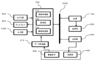
図1は、本実施例における光音響装置の概略図である。この装置は、光音響効果により発生した光音響波の受信信号に基づいて被検体Eの光学特性などの情報(機能情報)を取得する。また、図2は、本実施例における光音響装置の内部構成を示した図である。図1、図2に示すように、装置は基本的な構成要素として、光源100、光学系200、変換素子300、データ取得部310、支持体400、走査部500、カメラ部600、情報処理装置700、を備える。装置はまた、表示部としてのディスプレイ900、入力部1000、形状保持部1100、取り付け部1200を備えても良い。以下、光音響装置の各構成および測定に用いる構成について説明する。
[Example 1]
<Basic configuration>
FIG. 1 is a schematic diagram of a photoacoustic apparatus in the present embodiment. This apparatus acquires information (function information) such as optical characteristics of the subject E based on a received signal of a photoacoustic wave generated by the photoacoustic effect. FIG. 2 is a diagram showing an internal configuration of the photoacoustic apparatus in the present embodiment. As shown in FIG. 1 and FIG. 2, the apparatus includes, as basic components, a
(被検体)
測定の対象物である検体Eとして例えば、生体の乳房や手足などの部位、あるいは装置の調整などに用いる生体の音響特性と光学特性を模擬したファントムが挙げられる。音響特性とは具体的には音響波の伝搬速度および減衰率である。光学特性とは具体的には光の吸収係数および散乱係数である。被検体Eにおける、光吸収係数の大きい光吸収体として、生体では、ヘモグロビン、水、メラニン、コラーゲン、脂質などが挙げられる。ファントムでは、光学特性を模擬した物質を光吸収体として内部に封入する。なお、便宜上、図1において被検体Eは破線で示している。
(Subject)
Examples of the specimen E that is an object to be measured include a part of a living body such as a breast and limbs, or a phantom that simulates acoustic and optical characteristics of a living body used for adjustment of an apparatus. The acoustic characteristics are specifically the propagation speed and attenuation rate of acoustic waves. Specifically, the optical characteristics are light absorption coefficient and scattering coefficient. Examples of the light absorber having a large light absorption coefficient in the subject E include hemoglobin, water, melanin, collagen, and lipid in the living body. In the phantom, a substance simulating optical characteristics is enclosed inside as a light absorber. For convenience, the subject E is indicated by a broken line in FIG.
(光源)
光源100はパルス光を発生させる装置である。光源としては大出力を得るため、レーザーが望ましい。ただしフラッシュランプや発光ダイオードなどでもよい。光音響波を効果的に発生させるためには、被検体Eの熱特性に応じて十分短い時間に光を照射させなければならない。被検体Eが生体の場合、パルス光のパルス幅を数十ナノ秒以下にすることが望ましい。また、パルス光の波長としては、生体の窓と呼ばれる、波長700〜1200nm程度の近赤外領域が望ましい。この領域の光は比較的生体深部まで到達するので、深部の特性情報を取得できる。生体表面部の測定に限定すれば、500〜700nm程度の可視光から近赤外領域も使用してもよい。さらに、パルス光の波長は観測対象に対して吸収係数が高いことが望ましい。
(light source)
The
(光学系)
光学系200は、光源100で発生させたパルス光を、所望の光分布となるように形状や光密度を変更して被検体Eへ導く装置である。具体的には光学系200は、光ファイバー、ミラー、レンズ、プリズム、拡散板などの光学機器で構成できる。本実施例において光学系200は、半球状の支持体の曲率中心の領域を照明するように構成されている。
(Optical system)
The
また、生体組織に照射することが許される光の強度は、以下に示す安全規格によって最大許容露光量(MPE:maximum permissible exposure)が定められている。(IEC 60825−1:Safety of laser products、JIS C 6802:レーザー製品の安全基準、FDA:21CFR Part 1040.10、ANSI Z136.1:Laser Safety Standards、など)。 Further, the maximum permissible exposure (MPE) is determined by the safety standard shown below for the intensity of light allowed to irradiate the living tissue. (IEC 60825-1: Safety of laser products, JIS C 6802: Laser product safety standards, FDA: 21 CFR Part 1040.10, ANSI Z136.1: Laser Safety Standards, etc.).
最大許容露光量は、単位面積あたりに照射できる光の強度を規定している。このため被検体Eの表面の広い面積に一括して光を照射することにより、多くの光を被検体Eに導ける。その結果、光音響波を高いSN比で受信できる。このため光をレンズで集光させるより、図1の破線で示す様に、ある程度の面積に広げる方が好ましい。 The maximum allowable exposure defines the intensity of light that can be irradiated per unit area. For this reason, a large amount of light can be guided to the subject E by irradiating light onto a large area of the surface of the subject E at once. As a result, photoacoustic waves can be received with a high SN ratio. For this reason, it is preferable to extend the light to a certain area as shown by the broken line in FIG.
(変換素子)
変換素子300は、光音響波を受信して電気信号に変換する素子である。被検体Eからの光音響波に対して、受信感度が高く、周波数帯域が広いものが望ましい。変換素子300を構成する部材としては、PZT(チタン酸ジルコン酸鉛)に代表される圧電セラミック材料や、PVDF(ポリフッ化ビニリデン)に代表される高分子圧電膜材料などを使用できる。また、圧電素子以外の素子を用いても良い。例えば、cMUT(Capacitive Micro−machined Ultrasonic Transducers
)などの静電容量型の素子、ファブリペロー干渉計を用いた変換素子、などを使用できる。
(Conversion element)
The
), A conversion element using a Fabry-Perot interferometer, and the like can be used.
図3に、変換素子300の受信感度特性の一例を示す。横軸は、変換素子300の受信面の法線方向と光音響波の入射方向とのなす入射角度である。縦軸は角度ごとの受信感度特性を示す。図3の例では、受信面の法線方向から入射する場合の受信感度が最も高く、入射角度が大きくなるほど受信感度が低くなる。なお、本実施例に係る変換素子300は、円形の平面形状の受信面を有しているが、受信面の形状はこれに限定されない。
FIG. 3 shows an example of the reception sensitivity characteristic of the
また、受信感度が、最大値Sに対して半分のS/2になるときの入射角度をαとする。本実施例においては、変換素子300の受信面に入射角度α以下で光音響波が入射する領域を高感度に受信可能な受信領域とする。図1において、それぞれの変換素子300の最も受信感度の高い方向(指向軸)を一点鎖線で示す。
Further, the incident angle when the reception sensitivity is S / 2 that is half of the maximum value S is α. In the present embodiment, a region where a photoacoustic wave is incident on the receiving surface of the
なお、変換素子300にはデータ取得部310が接続され、A/D変換器と、FPGA、ASICなどの論理回路で構成された構成となっている。変換素子300を介して光音響波を受信して得た電気信号を、データ取得部310のA/D変換器を用いてデジタルデータに変換を行い、論理回路から情報処理装置700にデータ転送が行われる。また、信号強度を増幅する増幅器を設けることも好ましい。
Note that a
(支持体)
図4は、支持体400を上面から見た図である。本実施例の支持体400は、真球を半分に割った形状である半球状の容器である。円の中心部分は紙面に向かって奥方向に突出している。支持体400の内側の面には複数の変換素子300が設置され、支持体400の底部の中心には、パルス光を被検体Eに照射する光学系200と、被検体Eの外観の撮像部であるカメラ部600が設置されている。また、支持体400の内側には、後述する音響マッチング材800が充填される。支持体400は、これらの部材を支持するために、機械的強度が高い金属材料などを用いて構成することが好ましい。
(Support)
FIG. 4 is a view of the
支持体400に設けられた複数の変換素子300のそれぞれの素子の受信方向(指向軸)が半球の曲率中心に向かうように、複数の変換素子300は半球面上に配置されている。図1は半球状の支持体400を中心軸で切断した断面図であり、被検体Eの一部の領域(G)に、変換素子300の受信方向(一点鎖線)が集束する。このような素子配置により、支持体400の曲率中心付近で発生した光音響波をより高感度に受信できる。
The plurality of
このように複数の変換素子300を半球状に配置した場合、後述する方法で受信信号を用いて得られる被検体Eの機能情報は、半球の曲率中心の分解能が高く、中心から離れると分解能が低くなる。本実施例における高感度領域Gは、最も分解能の高い点から最も高い分解能の半分の分解能となるまでの領域のことを指し、図1の二点鎖線で囲まれた領域がこれに相当して高感度領域Gと定義される。なお、複数の変換素子300の配置はこれに限られない。例えば、必ずしも複数の変換素子300の指向軸が1点で交わらなくてもよい。
When the plurality of
また、支持体400の半球面に配置される変換素子300の実装パターンについては、
千鳥型配列、スパイラル配列、均等配列、ランダム配列等の様々な実装パターンが想定される。図4では、複数のスパイラル配列に沿って変換素子300を等間隔に実装したパターンを示している。このような配置の場合には、各素子の指向軸が全て半球の曲率中心を向いているので、球面の限られた一部分を未実装領域としても、領域Gの解像度に対しては大きな影響はない。
Further, regarding the mounting pattern of the
Various mounting patterns such as a staggered arrangement, a spiral arrangement, a uniform arrangement, and a random arrangement are assumed. FIG. 4 shows a pattern in which the
本実施例では、図4で示したように、支持体400の底部の極近傍には変換素子300を実装せず、代わりに光学系200とカメラ部600、610をまとめて配置している。これは、被検体Eに対して均等に光照射を行う目的と、カメラ部で被検体Eの全体像を撮影する目的である。ただし、カメラ等の配置はこれに限定されない。図4の配置によれば、極を中心にした同心円状のエリアを確保できる。すなわち、光学系200を極に配置した場合には、光学系200を中心にした同心円状のスペースを確保できる。そのため、カメラ部600と610の2箇所は、光学系200を挟んだ位置に設置されている。
In this embodiment, as shown in FIG. 4, the
なお、カメラ部を3箇所以上に設置する場合は、半球状の極を中心に均等に配置することが望ましい。例えば、4組のスパイラル配列を用いて変換素子300を配置する場合は、半球状の支持体400の中心部には4方向に変換素子が実装されない領域が存在する。例えば、中心部には光照射を行う光学系200を配置し、4方向の変換素子が実装されない領域の2つにカメラ、残りの2つの領域にマッチング液の給排水系の穴、残りにマッチング液の温度を監視する温度センサを実装しても良い。符号620、630で示される位置は、これらの構成を配置する候補となる。
In addition, when installing a camera part in three or more places, it is desirable to arrange | position equally centering on a hemispherical pole. For example, when the
n組のスパイラル配列を用いて変換素子300を配置する場合は、半球状の支持体400の中心部にはn方向に変換素子が実装されない領域が存在する。本発明のカメラはこのn方向に変換素子が実装されない領域に実装すると良い。スパイラル配列の組nが大きいと変換素子が実装されない領域の数は増えるが各々の面積は小さくなるので、カメラを実装する面積が得られなくなる。そのため、スパイラル配列の数は2以上、多くても8以下であると好適である。
When the
一方、高感度領域Gで発生した光音響波を高感度に受信できるように、支持体400により支持された複数の変換素子300の少なくとも一部の素子の最も受信感度の高い方向が高感度領域Gに向いていればよい。すなわち、複数の変換素子300の少なくとも一部の素子が高感度領域Gで発生する光音響波を高感度に受信することができるように支持体400に配置されていればよい。
On the other hand, the direction with the highest reception sensitivity of at least some of the plurality of
また、複数の変換素子300の最も受信感度の高い方向同士が平行であるときと比べて、複数の変換素子300の最も受信感度の高い方向に沿った軸(指向軸)が集まるように複数の変換素子300が支持体400に配置されていればよい。また、複数の変換素子300の受信面が支持体400に沿うように、複数の変換素子300を配置しても良い。支持体400の形状は、本実施例のような半球状に限らず、上記のように複数の変換素子300を配置できる限り、いかなる形状であってもよい。
Further, as compared to the case where the directions with the highest reception sensitivity of the plurality of
本実施例に係る「曲面」は真球上の面以外の曲面も含まれる。すなわち、本実施例に係る曲面は、曲面と見なせる程度の表面上の凹凸がある面や、曲面と見なせる程度の楕円体(楕円を三次元へ拡張した形であり、表面が二次曲面からなる形)上の面も含む。また、本実施例の支持体は、複数の平面がつながって形成された面でもよい。 The “curved surface” according to the present embodiment includes a curved surface other than a surface on a true sphere. That is, the curved surface according to the present embodiment is a surface with irregularities on the surface that can be regarded as a curved surface, or an ellipsoid that can be regarded as a curved surface (an ellipse is expanded to three dimensions, and the surface is a quadric surface) Shape) Including the upper surface. Further, the support of this embodiment may be a surface formed by connecting a plurality of flat surfaces.
図1のように、高感度領域Gが、被検体Eが位置すると想定される位置に形成されるように複数の変換素子300を配置することが好ましい。さらに、図1のように被検体Eの形状を保持する形状保持部1100がある場合は、形状保持部1100付近に高感度領域
が形成されるように複数の変換素子300を配置することが望ましい。
As shown in FIG. 1, it is preferable to arrange a plurality of
(走査部)
走査部500は、支持体400の位置を図1のX,Y,Z方向に移動することにより、被検体Eと支持体400の相対的な位置関係を変更する装置である。このため走査部500は、不図示のX,Y,Z方向のガイド機構と、X,Y,Z方向の駆動機構と、支持体400のX,Y,Z方向の位置を検出する位置センサを備えている。例えば、ある時点での相対的な位置関係を第一の相対位置、別の時点での、第一の相対位置とは異なる位置関係を第二の相対位置と定義できる。
(Scanning part)
The
図1に示すように、走査部500の上に支持体400が積載されるため、ガイド機構としては大きな荷重に耐えられるリニアガイドなどが好ましい。また、駆動機構としては、リードスクリュー機構、リンク機構、ギア機構、油圧機構、などを利用できる。駆動力はモーターなどを利用できる。また、位置センサとしては、エンコーダー、可変抵抗器、などを用いたポテンショメータなどを利用できる。
As shown in FIG. 1, since the
なお、本発明においては、被検体Eと支持体400との相対的な位置を変化させればよいため、支持体400を固定して被検体Eを移動させてもよい。被検体Eを移動させる場合は、被検体Eを支持する支持部(不図示)を動かすことで被検体Eを移動させる構成が考えられる。さらに、被検体Eと支持体400の両方を移動させてもよい。
In the present invention, since the relative position between the subject E and the
また、移動は連続的に行うのが望ましいが、一定のステップを繰り返して移動しても良い。走査部500は、電動制御のステージであることが望ましいが、手動制御のステージでも良い。ただし、ここに挙げたものだけに限定されず、被検体Eと支持体400のうち少なくとも一方を移動可能に構成されていればよい。
In addition, the movement is preferably performed continuously, but the movement may be performed by repeating certain steps. The
(カメラ部)
カメラ部600は、撮像部として被検体Eの外観の画像を取得する撮像装置である。カメラ部600を、支持体400の底部の中心近傍に設置することは、被検体Eの全体像を撮影するために好適である。カメラ部600から出力された画像信号に基づいて、情報処理装置700の画像処理部730により撮像画像が生成される。カメラ部600としては、通常の光学撮像装置のほか、被検体に応じて外観を撮像できる装置を利用できる。またカメラ部600は動画像を撮影できるものでも良い。
(Camera part)
The
ここで、半球の極に関してカメラ部600の対角位置に、別のカメラ部610を追加することも好ましい。カメラ部600と610が異なる位置から撮像した2枚の画像を用いた、ステレオ法などの三次元計測技術により、被検体Eの形状情報を精度よく取得できる。ステレオ法においては、異なる位置のカメラで撮影した2つの像の間で任意の領域をマッチングする。そして、得られた視差に基づき、三角測量を用いて距離を計測できる。ステレオ法を用いて被検体Eの位置情報を検出するには、異なる位置で同時に撮影した2枚以上の撮像画像上で、相互に対応する特徴点(対象物上の同一点を表す)を求めて、この特徴点を計測する必要がある。特徴点として例えば、インクやシールを用いたマーカや、ホクロまたは乳頭のような生体上の特徴的な構造物、などが利用できる。そして、画像の間で対応する特徴点を比較することで、位置情報が得られる。
Here, it is also preferable to add another
(情報処理装置)
情報処理装置700は、情報処理部710と記憶部720、および画像処理部730を有している。情報処理部710は典型的には演算処理CPUで構成され、画像処理部730は画像処理GPU(Graphic Processor Unit)などで構成されている。なお、情報処理部や画像処理部は、1つの素子や回路から構成されるだけではな
く、複数の素子や回路から構成されていてもよい。また、情報処理装置700が行う各処理をいずれの素子や回路が実行してもよい。記憶部720は、典型的にはROM、RAM、およびハードディスクなどの記憶媒体から構成される。なお、記憶部は、1つの記憶媒体から構成されるだけでなく、複数の記憶媒体から構成されていてもよい。情報処理装置700は単体の装置として構成されても良いし、複数のブロックが有線または無線で接続され、共同動作するように構成されても良い。
(Information processing device)
The
情報処理部710と画像処理部730により、複数の変換素子300から出力された電気信号を元に信号処理(画像再構成)を施すことで、被検体Eの機能情報を生成できる。また、制御部としての情報処理部710は、バス2000を介して光音響装置を構成する各構成の動作を制御することができる。また、情報処理装置700は、同時に複数の信号をパイプライン処理できるように構成されていることが好ましい。これにより、被検体Eの機能情報を生成するまでの時間を短縮することができる。
By performing signal processing (image reconstruction) based on the electrical signals output from the plurality of
なお、情報処理装置700が行うそれぞれの処理を、情報処理部710に実行させるプログラムとして記憶部720に保存しておくこともできる。ただし、プログラムが保存される記憶部720には、不揮発性の記録媒体が必要である。情報処理装置700の実行する機能のうち、位置情報取得に関する部分は位置情報取得手段とみなすことができる。情報処理装置700の実行する機能のうち、特性情報取得に関する部分は特性情報取得手段とみなすことができる。特性情報取得手段が、第一の相対位置において取得された電気信号に基づいて被検体内部の特性情報を取得した時、その特性情報を第一の特性情報と定義できる。特性情報取得手段が、第二の相対位置において取得された電気信号に基づいて被検体内部の特性情報を取得した時、その特性情報を第二の特性情報と定義できる。情報処理装置700の実行する機能のうち、第一の特性情報と第二の特性情報の間における位置ずれの、位置情報に基づく補正に関する部分は、補正手段とみなすことができる。
Each process performed by the
(音響マッチング材)
音響マッチング材800は、被検体Eと変換素子300との間の空間を満たし、被検体Eと変換素子300を音響的に結合させる。形状保持部1100を用いる場合、変換素子300と形状保持部1100との間の空間、および形状保持部1100と被検体Eとの間の空間に音響マッチング材800を配置してもよい。それぞれの空間における音響マッチング材800は、同種でも良いし異種でも良い。
(Acoustic matching material)
The
音響マッチング材800は、被検体Eおよび変換素子300に音響インピーダンスが近い材料であることが好ましい。さらに、音響マッチング材800は、被検体Eおよび変換素子300の中間の音響インピーダンスを有する材料であることがより好ましい。また、音響マッチング材800は、光源100で発生するパルス光を透過する材料であることが好ましい。また、音響マッチング材800は液体であることが好ましい。具体的に音響マッチング材800としては、水、ひまし油、超音波用のジェルなどを利用できる。
The
(ディスプレイ)
ディスプレイ900は、情報処理装置700から出力される被検体Eの機能情報を分布画像や高感度関心領域の数値データなどで表示する装置である。例えば、液晶ディスプレイ、プラズマディスプレイ、有機ELディスプレイ、FEDなどを利用できる。なお、ディスプレイ900は、本発明の被検体情報取得装置とは別に提供されても良い。
(display)
The
(入力部)
入力部1000は、ユーザーが情報処理装置700に所望の情報を入力したり選択したりするための装置である。入力部1000としては、キーボード、マウス、タッチパネル、ダイヤル、およびボタンなどを利用できる。入力部1000としてタッチパネルを採用
する場合、ディスプレイ900が入力部1000を兼ねるタッチパネルであってもよい。
(Input section)
The
(形状保持部)
形状保持部1100は、被検体Eの形状を一定に保つための部材である。形状保持部1100は、取り付け部1200に取り付けられている。なお、被検体Eの形状やサイズなどに合わせて、複数の形状保持部1100を交換して用いてもよい。この場合、取り付け部1200は複数の形状保持部を取り付け、取り外し可能に構成する。
(Shape holding part)
The
形状保持部1100を介して被検体Eに光を照射する場合、形状保持部1100は照射光に対して透明であることが好ましい。例えば、形状保持部1100の材料としては、ポリメチルペンテンやポリエチレンテレフタラートなどを用いることができる。また、被検体Eが乳房である場合、乳房形状の変形を少なくして形状を一定に保持するために、形状保持部1100の形状としては、球をある断面で切った球冠形状や、カップ状などが好ましい。なお、被検体Eの体積や保持後の所望の形状に応じて、形状保持部1100の形状を適宜設計できる。
When irradiating the subject E with light through the
<光音響装置の作動>
次に、被検体Eの位置情報を取得して、被検体Eの機能情報が生成されるまでの動作について、図5に示した工程図を用いて説明する。ステップS100は、形状保持部1100に被検体Eを挿入する工程である。このとき、支持体400と形状保持部1100との間、および形状保持部1100と被検体Eとの間に、音響マッチング材800を満たす。
<Operation of photoacoustic device>
Next, operations from obtaining position information of the subject E to generating function information of the subject E will be described with reference to the process diagram shown in FIG. Step S <b> 100 is a step of inserting the subject E into the
ここで、被検体Eの体積が形状保持部1100の容積に対して大きければ、被検体Eの外形形状を形状保持部1100の外形形状と同じとみなせるので、生体の体動の影響を考慮する必要は無い。しかしながら、被検体Eの体積には個人差が有り、形状保持部1100の容量より小さい場合には、音響マッチング材800が充填された隙間が生じる。その結果、生体の体動の影響が起きる。特にスクリーニング診断のような画像装置として使用する場合には、被検体Eの様々なサイズを想定して大きめの形状保持部を設けることになるので、体動の影響は避けられない。
Here, if the volume of the subject E is larger than the volume of the
ステップS200は、走査部500により、支持体400を移動領域内の所望の位置へ移動させる工程である。走査部500は、移動領域内の測定が開始される第一の測定位置に支持体400を移動させる。第一の測定位置における支持体400の位置情報が情報処理装置700に送られ、記憶部720に第一の測定位置情報として保存される。
Step S <b> 200 is a step in which the
この時の移動領域としては、被検体Eを保持する形状保持部1100で囲われた領域を設定することが望ましい。すなわち、領域設定部としての情報処理部710が、形状保持部1100の形状情報に基づいて支持体400の移動領域を設定する。なお、技師などが入力部1000で領域を設定してもよい。またこのとき領域以外にも、測定に関する諸条件(測定精度、測定時間、測定対象、所与の光学係数など)の入力を促しても良い。
As the moving region at this time, it is desirable to set a region surrounded by the
図6は、走査に伴う高感度領域Gの移動の軌跡を、形状保持部1100のサイズと対比させた様子を垂直方向から見た様子を示す。情報処理部710は、図6に示すように、高感度領域Gが形状保持部1100の内側に形成されるように、支持体400のX,Y,Z方向の移動領域を設定する。より好ましくは、被検体内部に高感度領域Gが形成する。高感度領域Gの位置や大きさは、複数の変換素子300の配置や、どの程度の測定精度を求めるかの条件によって決定される。そこで、情報処理部710は、形状保持部1100の形状情報と支持体400上の複数の変換素子300の配置の情報とに基づいて、高感度領域Gが被検体内部に形成されるように移動領域を設定する。
FIG. 6 shows a state in which the locus of movement of the high sensitivity region G accompanying scanning is compared with the size of the
なお、予め複数の変換素子300の配置から決定される高感度領域Gの大きさや位置の情報が記憶部720に格納されていてもよい。この場合、情報処理部710は記憶部720から読み出された高感度領域Gの大きさや位置の情報と、形状保持部1100の形状情報とに基づいて移動領域を設定すればよい。
Note that information on the size and position of the high-sensitivity region G determined in advance from the arrangement of the plurality of
また、情報処理部710は、設定された移動領域内における光音響波の測定位置を適宜設定する。ここでの測定位置は例えば、走査中に光を照射する位置や、光照射に続く一定時間内に音響波を受信する位置として表される。例えば情報処理部710は、移動領域内に一定の間隔で測定位置を設定し、光源100および走査部500の駆動を制御する。
In addition, the
さらに、測定位置間で高感度領域Gが重なるように光源100および走査部500の駆動が制御されることが好ましい。すなわち、本実施例において高感度領域Gは球形状であるため、支持体400が高感度領域Gの半径と等しい距離だけ移動するまでに少なくとも一回はパルス光が照射されることが好ましい。これは、支持体400が高感度領域Gの半径と等しい距離を移動する間に、少なくとも1回は受信信号を取得することを意味する。ある1回の光照射から次の光照射までの時間に支持体400を移動させる距離が小さいほど、重ね合わせの領域が増えるのでS/Nが向上する。しかしこの場合、移動速度が遅いため測定に時間がかかる。よって、移動速度と受信信号の取得時間の間隔に関しては、所望のS/Nと測定時間を加味して、適宜設定すると良い。
Furthermore, it is preferable to control the driving of the
ステップS300は、光源100の光を被検体Eに照射して、発生した光音響波を複数の変換素子300で検出して受信信号を取得する工程である。情報処理部710は、第一の測定位置情報に基づき支持体400が第一の測定位置に位置すると判断すると、光源100が光を発生するように制御信号を出力する。光は光学系200によって導かれ、音響マッチング材800を介して被検体Eに照射される。そして、被検体Eに照射された光が被検体E内で吸収され光音響波が発生する。
Step S300 is a step of irradiating the subject E with the light from the
複数の変換素子300は、音響マッチング材800内を伝搬した被検体E内で発生した光音響波を受信し、データ取得部310により受信信号としての電気信号に変換する。データ取得部310から出力された電気信号は情報処理装置700に送られ、前述の第一の測定位置情報と関連付けされて、記憶部720に第一の測定位置における電気信号として保存される。なお本ステップの受信信号取得は、支持体の停止と移動を繰り返し、停止位置で信号取得する方式に限るものではなく、支持体400を連続的に移動させながら光照射と信号取得を行うようにしても良い。この手法によれば、支持体400の停止と移動を繰り返す場合と比較して高速に走査が行えることに加えて、支持体400に満たされた音響マッチング材800の液面の乱れを抑制しやすいという利点がある。
The plurality of
ステップS400は、受信信号に基づいて被検体Eの機能情報を取得する工程である。情報処理部710は、S300で取得された受信信号に対して画像再構成アルゴリズムに基づく処理を施すことにより被検体Eの機能情報を取得する。機能情報を取得するための画像再構成アルゴリズムとしては、トモグラフィー技術で通常に用いられるタイムドメイン、あるいはフーリエドメインでの逆投影などが用いられる。なお、再構成に多くの時間をかけられる場合は、繰り返し処理による逆問題解析法などを用いてもよい。前述したように、S300で取得された受信信号は被検体E内で発生した光音響波を高感度に受信して得られた高感度領域Gに由来する受信信号である。そのため、本工程では被検体E内の機能情報を精度良く、すなわち、高い分解能および定量性をもって取得できる。
Step S400 is a step of acquiring function information of the subject E based on the received signal. The
S500は、光源100の光の照射に続けて、カメラ部600、610で被検体Eを同時に撮影して撮像画像を生成する工程である。この時に、光源100から照射した光が撮像画像に与える影響を低減することが好ましい。例えば、撮影のタイミングを更に遅延さ
せる方法や、カメラ部のレンズに光源100の波長をカットするフィルターを入れる方法、逆にカメラ部の撮影をした後に光の照射を行う方法など、が考えられる。また、1台の
カメラを用いて600と610の2つの場所の画像を同時に取得する方法でも構わない。すなわち、2つの場所にレンズを設けミラーで集光して1台のカメラに取り込み、同時に2つの画像を撮影することも可能である。
S500 is a process of generating a captured image by simultaneously photographing the subject E with the
S600は、複数の撮像画像から被検体Eの位置情報を取得する工程である。同時に撮影された2枚の撮像画像を用いて、ステレオ法を用いた特徴点Pの距離を算出する方法について説明する。 S600 is a step of acquiring position information of the subject E from a plurality of captured images. A method of calculating the distance of the feature point P using the stereo method using two captured images taken at the same time will be described.
図7のように、それぞれのカメラ部の位置関係Lが求められているとすると、2台のカメラ部を用いて被検体を撮影して、被検体上のある特徴点Pとカメラ部に投影される画像の関係は、三角測量で求められる。すなわち、注目している特徴点Pがカメラ部600に写る点の座標P1により角度θ1が算出され、カメラ部610に写る点の座標P2により角度θ2が算出される。従って、2点間の距離Lと両端角θ1、θ2により、2台のカメラ部から特徴点Pまでの距離Hを以下の式で取得できる。

したがって、光照射を行う前に2台のカメラ部で被検体Eを撮影して、被検体Eの各特徴点の位置情報を得ることができるので、被検体Eの受信信号を得た時の位置情報として対応をとることが可能である。
As shown in FIG. 7, when the positional relationship L of each camera unit is obtained, the subject is imaged using two camera units, and projected onto a certain feature point P on the subject and the camera unit. The relationship between the images to be obtained is obtained by triangulation. In other words, the angle θ1 is calculated from the coordinate P1 of the point where the feature point P of interest appears in the
Therefore, since the subject E can be photographed by two camera units before the light irradiation and the position information of each feature point of the subject E can be obtained, the reception signal of the subject E is obtained. It is possible to take correspondence as position information.
S700は、移動領域内での測定を繰り返すかどうかを判断する工程である。移動領域内に測定が済んでいない箇所が残っている場合、測定を繰り返すと判断される。そして、走査部500により、被検体と支持体の相対的な位置関係を変化させる。その結果、設定された移動領域内の第一の測定位置とは異なる第二の測定位置に支持体400が移動する。そして、支持体400が第二の測定位置に位置するときに第一の測定位置における測定と同様の工程を行い、第二の測定位置における電気信号と撮像画像が取得される。一方、S200で設定された移動領域内の全ての測定位置における被検体Eの電気信号と撮像画像が取得された場合、次のステップに移行する。この時、被検体Eの位置情報に関しては、第一の測定位置で取得した位置を基準値として確保し、第二の測定位置以降で取得した位置は差分の加減で管理する方法が望ましい。ここで第一の測定位置および第二の測定位置として示した書く位置は、本発明の第一の相対位置と第二の相対位置として捉えて良い。
S700 is a step of determining whether or not to repeat the measurement in the moving area. If there is an unmeasured portion in the moving area, it is determined that the measurement is repeated. The
S800は、被検体Eの位置情報を、高感度領域Gの測定位置情報に対応させることで、被検体Eのボリューム情報を取得する工程である。高感度領域Gの測定位置情報は、形状保持部1100の形状情報と、支持体400のX,Y,Z方向の移動領域に関する情報から算出された位置情報である。なお、情報処理部710により設定された測定位置情報は、記憶部720に保存されている。この測定位置情報は、支持体400と形状保持部1100の相対位置を表わしていて、高感度領域Gの位置は支持体400の走査位置にあわせて移動していることが示されている。
S800 is a step of acquiring the volume information of the subject E by associating the position information of the subject E with the measurement position information of the high sensitivity region G. The measurement position information of the high sensitivity region G is position information calculated from the shape information of the
図8(a)は、被検体Eが形状保持部1100で固定され位置情報に変動が無い場合の、XZ平面における高感度領域Gの移動の推移を模式的に示した図である。図においては高感度領域GがX方向に直線移動しているように描いているが、実際の移動方向はこれに
限られない。本図は、例えば、スパイラル移動または往復移動する高感度領域Gを、直線移動に変換して示した図だと考えても良い。本実施例における高感度領域Gは球形状である。支持体400が高感度領域Gの半径と等しい距離を移動する間に、少なくとも1回は光音響測定が行われ、被検体Eの撮像画像と受信信号が取得される。そして、記憶部720に保存されている測定位置情報(a0〜a8)を元に画像が重ね合わせられて、被検体全域のボリューム情報が取得される。
FIG. 8A is a diagram schematically showing the transition of the movement of the high sensitivity region G in the XZ plane when the subject E is fixed by the
なお、重ね合わせる方向は移動方向(図8ではX方向)に限られない。例えば図6のようにボリューム情報が得られる場合は、複数の方向に重ね合わせが可能である。重ね合わせの方法は任意であり、例えば重複するボクセルの値を単純に平均化する方法や、対象ボクセルの周囲の一定範囲内のボクセル値を重み付けして利用する方法がある。 Note that the overlapping direction is not limited to the moving direction (X direction in FIG. 8). For example, when the volume information is obtained as shown in FIG. 6, it is possible to superimpose in a plurality of directions. The method of superposition is arbitrary. For example, there are a method of simply averaging the values of overlapping voxels and a method of weighting and using voxel values within a certain range around the target voxel.
次に、被検体Eに体動がある場合の、XZ平面における高感度領域Gの位置推移の模式図を図8(b)に示す。実際には高感度領域Gが上下するのではなく、被検体のうち高感度領域と重畳する部分が上下するが、本図では便宜上、高感度領域により取得されたボリューム情報の上下動として示す。この場合、被検体Eの基準位置からの差分を算出して重ね合わせを行う必要がある。そこで、S600で得られた被検体Eの位置情報と、記憶部720に保存されている測定位置情報から、高感度領域Gの被検体Eに対する位置を算出して、ボリューム情報への重ね合わせ位置を補正する。このように、体動に応じた位置情報を反映した補正を行った上でボリューム重ね合わせが行われることで、好適な情報が得られる。
Next, FIG. 8B shows a schematic diagram of the position transition of the high sensitivity region G in the XZ plane when the subject E has body movement. Actually, the high-sensitivity region G does not move up and down, but the portion of the subject that overlaps with the high-sensitivity region moves up and down. In this case, it is necessary to perform superposition by calculating a difference from the reference position of the subject E. Therefore, the position of the high sensitivity region G with respect to the subject E is calculated from the position information of the subject E obtained in S600 and the measurement position information stored in the
図8(b)では、基準位置b0に対してのZ方向の位置変動は、破線で示した基準位置との差分として現れる。そして、b1〜b8の測定位置情報に被検体位置の差分情報を対応させている。したがって、被検体Eの上下動作に合わせて、ボリューム重ね合わせに用いる情報源を変化させることが可能になる。被検体の上下動があった場合の重ねあわせ方法として、高感度領域Gから少しずれた位置のデータを使用できる。例えば図8(b)のb1〜b3では、高感度領域Gが基準位置の高さより下にある。すなわち被検体はZ方向上方にずれたと考えられる。 In FIG. 8B, the position fluctuation in the Z direction with respect to the reference position b0 appears as a difference from the reference position indicated by a broken line. The difference information of the subject position is associated with the measurement position information b1 to b8. Therefore, the information source used for volume superposition can be changed in accordance with the vertical movement of the subject E. As an overlapping method when the subject moves up and down, data at a position slightly deviated from the high sensitivity region G can be used. For example, in b1 to b3 of FIG. 8B, the high sensitivity region G is below the height of the reference position. That is, it is considered that the subject has shifted upward in the Z direction.
よって、b0と同じ高さのイメージングを希望する場合、高感度領域GよりもZ方向上方のボリューム情報を利用すると良い。一方、b5,b6では被検体がZ方向下方にずれたと考えられるので、高感度領域Gより下方のボリューム情報を利用する。逆に、重ね合わせ後の情報においてZ方向での高さが揃わなくなるものの、あくまでも高感度領域Gで取得したボリューム情報を使用した重ねあわせを行っても良い。この場合でも、支持体400をZ方向にも走査することによって、被検体の広い範囲を高感度領域Gに含めることができる。
Therefore, when imaging at the same height as b0 is desired, it is preferable to use volume information above the high sensitivity region G in the Z direction. On the other hand, in b5 and b6, since it is considered that the subject has shifted downward in the Z direction, volume information below the high sensitivity region G is used. Conversely, although the height in the Z direction is not uniform in the information after superposition, superposition using volume information acquired in the high sensitivity region G may be performed. Even in this case, a wide range of the subject can be included in the high sensitivity region G by scanning the
本実施例によれば、被検体の位置情報を検出して、高感度領域Gとの相対位置の変化を補正することにより、ボリューム情報の重ね合わせを良好に実施し、所望の領域における被検体の特性情報分布を精度よく生成できる。その結果、体動などによる被検体Eの測定位置のずれを低減し、分解能の低下を起こすことなく被検体の広い範囲をイメージングできるようになる。本実施例ではZ方向の被検体の位置変化の補正について説明した。しかし上記の手法は、X方向、Y方向の体動や、それらを組み合わせた体動にも適用可能である。本発明は、被検体の保持部材がない場合、被検体と保持部材との間に間隙がある場合、保持部材がシート部材等の柔らかい材質で構成される場合など、被検体の形状が体動に応じて変化しやすい場合に特に有効である。 According to the present embodiment, the position information of the subject is detected, and the change of the relative position with the high sensitivity region G is corrected, so that the volume information is superposed well, and the subject in the desired region is obtained. The characteristic information distribution can be generated with high accuracy. As a result, the displacement of the measurement position of the subject E due to body movements can be reduced, and a wide range of the subject can be imaged without causing a reduction in resolution. In the present embodiment, the correction of the position change of the subject in the Z direction has been described. However, the above method can also be applied to body movements in the X direction and the Y direction, or body movements combining them. In the present invention, when there is no holding member for the subject, there is a gap between the subject and the holding member, or when the holding member is made of a soft material such as a sheet member, This is particularly effective when it is likely to change depending on the condition.
(変形例1)
図5のフローでは、測定位置ごとに光照射と光音響波受信を行い、ボリューム情報を得
ていた。そして移動領域全体の走査が完了したのちに重ねあわせ処理を行っていた。しかし、カメラや情報処理装置の性能によっては、測定位置ごとに体動の有無や程度を検出することも可能である。その場合、走査部の性能によっては、次の測定位置において体動の影響を補正し、所望の位置に高感度領域Gが形成されるように支持体を移動させても良い。
(Modification 1)
In the flow of FIG. 5, light irradiation and photoacoustic wave reception are performed for each measurement position to obtain volume information. Then, after the scanning of the entire moving area is completed, the overlapping process is performed. However, depending on the performance of the camera or information processing apparatus, it is also possible to detect the presence or absence and degree of body movement for each measurement position. In this case, depending on the performance of the scanning unit, the influence of body movement may be corrected at the next measurement position, and the support may be moved so that the high sensitivity region G is formed at a desired position.
(変形例2)
本発明は、半球形の支持体に指向軸が互いに異なる変換素子が高感度領域を形成するように配置された場合に限定されない。本発明は、被検体の形状が体動などにより変化しやすく、変換素子と被検体が音響マッチング材等を介して間隔をおいて配置されている場合に好適で用いられる。例えば支持体として、単素子プローブ、1Dリニアプローブ、2D平面プローブを用いる場合でも、位置情報を用いた本発明の手法は適用できる。
(Modification 2)
The present invention is not limited to the case where conversion elements having different directivity axes are arranged on a hemispherical support so as to form a high sensitivity region. The present invention is suitably used when the shape of the subject is likely to change due to body movement or the like, and the conversion element and the subject are arranged at an interval via an acoustic matching material or the like. For example, even when a single element probe, a 1D linear probe, or a 2D planar probe is used as a support, the method of the present invention using position information can be applied.
[実施例2]
実施例1では、被検体Eの位置情報を取得する工程として、2台のカメラで撮影した画像を使ったステレオ法について説明した。本実施例では、単眼のカメラを移動させて撮影するカメラ移動方法について説明する。
[Example 2]
In the first embodiment, the stereo method using images taken by two cameras has been described as the process of acquiring the position information of the subject E. In this embodiment, a camera moving method for shooting by moving a monocular camera will be described.
2台のカメラを用いて同時に撮影をする実施例1に対して、単眼のカメラを移動させて異なる位置で撮影するカメラ移動方式でも、同様のステレオ法を用いた位置情報の取得が可能となる。図9で示したカメラ600と、特徴点Pの配置で説明する。まず、特徴点Pをカメラ600が左側の位置で撮影して、第一の画像を得る。続いてカメラを距離Lだけ移動させて、右側の位置で撮影して第二の画像を得る。そして、第一の画像と第二の画像を用いて、被検体上の特徴点Pとカメラ部に投影される画像の関係から、三角測量によって距離Hを算出できる。
In contrast to the first embodiment in which shooting is performed simultaneously using two cameras, position information can be acquired using the same stereo method even in a camera moving method in which a single-lens camera is moved and shot at different positions. . This will be described with reference to the
しかしながら、カメラが距離Lを移動している時間T2に、特徴点PがP’に移動した場合、三角測量で計測される距離H’は、左側の地点から観察した特徴点Pと、右側の地点から観察した特徴点P’の交点となるので、実際の距離Hとは異なった値となる。したがって、被検体Eの位置変動の周期1/T1に対して、カメラの移動に要する時間T2の比率が十分に小さいこと(T1>>T2となっていること)が求められる。 However, when the feature point P moves to P ′ at the time T2 when the camera moves the distance L, the distance H ′ measured by triangulation is equal to the feature point P observed from the left point and the right point. Since this is the intersection of the feature points P ′ observed from the point, the actual distance H is a different value. Therefore, it is required that the ratio of the time T2 required for moving the camera to the period 1 / T1 of the position fluctuation of the subject E is sufficiently small (T1 >> T2).
以上説明したように、本実施例に係る被検体情報取得装置は、簡易な構成であっても、被検体の位置情報を検出して、高感度領域Gの位置ずれを補正できる。その結果、所望の領域における被検体のボリューム情報を高精度に取得できる。 As described above, the subject information acquisition apparatus according to the present embodiment can detect the position information of the subject and correct the positional deviation of the high sensitivity region G even with a simple configuration. As a result, the volume information of the subject in the desired region can be acquired with high accuracy.
[実施例3]
実施例1、実施例2では、被検体Eの位置情報を取得する工程として、受動型計測の一例であるステレオ法について説明した。本実施例では、対象となる被検体Eに対して、計測の補助となる特定の光や電波等を照射する能動型計測について説明する。
[Example 3]
In the first and second embodiments, the stereo method, which is an example of passive measurement, has been described as the process of acquiring the position information of the subject E. In the present embodiment, an active measurement in which specific light, radio waves, or the like that assist measurement is applied to the subject E to be measured will be described.
能動型計測とは、三次元計測をするために光、電波、音波などを対象の被検体Eに照射し、その情報を利用して計測を行う方法である。例えば「光レーダー法」、「アクティブステレオ法」、「照度差ステレオ法」などが知られている。「光レーダー法」とは、物体に光、電波、超音波等を当て、戻ってくるまでの時間によって距離画像を得る方法である。「アクティブステレオ法」とは、カメラを2台使う代わりに、1台を光を投影する装置に置き換えて計測を行う方法で、投影する光の種類により様々な手法にさらに分類される。「照度差ステレオ法」とは、対象の物体に対して複数の光源を使って、光源を切り替えながら写した複数の画像から面の方向を求める手法である。光源に近い物体の面の面素が明るく写ることで光源方向に傾きを計測できるので、これを複数得ることで立体を計測で
きる。
Active measurement is a method in which light, radio waves, sound waves, or the like are irradiated onto a target subject E to perform three-dimensional measurement, and measurement is performed using the information. For example, “light radar method”, “active stereo method”, “illuminance difference stereo method” and the like are known. The “light radar method” is a method of obtaining a distance image according to the time taken to return an object by applying light, radio waves, ultrasonic waves or the like to the object. The “active stereo method” is a method of performing measurement by replacing one camera with a device that projects light instead of using two cameras, and is further classified into various methods depending on the type of light to be projected. The “illuminance difference stereo method” is a method for obtaining the direction of a surface from a plurality of images taken while switching light sources using a plurality of light sources for a target object. Since the surface element of the surface of the object close to the light source appears bright, the tilt can be measured in the direction of the light source.
「アクティブステレオ法」の様々な手法は、スポット光投影法、スリット光投影法(光切断法)、パターン光投影法などに分類される。スリット光投影法とは、スリット光を物体に投影した状態で撮影を行い、その光の変化の度合いを取り出して計測を行う方法であり、1回の撮影で1本のスリットによる光切断像が得られる。パターン光投影法とは、単一の投影パターン(例えばランダムなドットがちりばめられた大きな四角形パターン)を常に対象表面に投影しておき、撮影した撮像画像からパターン内の各場所の移動量を画像処理でとらえる方法である。 Various methods of the “active stereo method” are classified into a spot light projection method, a slit light projection method (light cutting method), a pattern light projection method, and the like. The slit light projection method is a method in which the image is taken with the slit light projected on an object, and the degree of change in the light is taken out and measured. can get. Pattern light projection is a method in which a single projection pattern (for example, a large square pattern with random dots interspersed) is always projected onto the target surface, and the amount of movement at each location in the pattern is captured from the captured image. It is a method of capturing by processing.
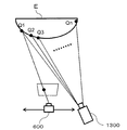
本実施例では、能動型計測の「アクティブステレオ法」の中のひとつである、パターン光投影法について説明する。図10は、パターン光投影法で三角測量を本実施例に適用した構成図である。この方法も三角測量に基づく手法である。具体的には、被検体Eに対してあらかじめ定められた位置にあるパターン光投影装置1300から一定の方向にパターン光Q1〜Qnを投影し、被検体E上に映ったそのパターン光を別の位置に設置したカメラ600により撮影する。この時、カメラ600の撮像画像に映っているパターン光Q1〜Qnの位置から、パターン光投影装置1300の位置とカメラ600の位置をもとに三角測量の原理を利用して対象物までの距離を求める。パターン光を用いて特徴点を抽出すれば、乳房のような表面に特徴点が無い被検体に対しても効果的である。
In this embodiment, a pattern light projection method, which is one of the “active stereo methods” of active measurement, will be described. FIG. 10 is a configuration diagram in which triangulation is applied to the present embodiment by the pattern light projection method. This method is also based on triangulation. Specifically, the pattern light Q1 to Qn is projected in a certain direction from the pattern
本実施例では、支持体400に実装されたカメラ600は、被検体Eに対して任意の位置に移動する構成となっているが、パターン光投影装置1300は被検体Eに対して同じ位置に固定されていることが望ましい。すなわち、パターン光Q1〜Qnを被検体Eの同じ位置(特徴点)に常に照射させて位置変動を計測する場合には、パターン光投影装置1300の位置は固定する必要があり、設置場所は支持体400や走査部500から分離された位置となる。しかしながら、被検体E表面の特徴点に対する位置変動の測定だけでなく、被検体Eの3次元形状を測定するような場合には、カメラ600とパターン光投影装置1300を同一の支持体400に設置して運用することも可能である。
In this embodiment, the
以上説明したように、本実施例の被検体情報取得装置は、被検体の位置情報を検出して、高感度領域Gの位置ずれを補正することにより、所望の領域における被検体のボリューム情報の分解能を低下させない効果を有する。 As described above, the subject information acquisition apparatus according to the present embodiment detects the position information of the subject and corrects the positional deviation of the high-sensitivity region G, thereby correcting the volume information of the subject in the desired region. It has the effect of not reducing the resolution.
[実施例4]
上述の実施例では、被検体に対する支持体400の相対位置を様々に変えて、各相対位置において取得された受信信号に基づいて、被検体Eの機能情報を取得する例を説明した。すなわち、1回のレーザー照射によって得られた受信信号に基づいて被検体Eの機能情報を取得していた。この手法によれば、レーザー照射のタイミング毎に高感度領域Gから得られた受信信号に対して画像再構成アルゴリズムの信号処理を行うことで、支持体400の動きに合わせた高感度領域Gの機能情報を毎回生成することが可能であった。そのため、支持体を移動させながら逐次処理(リアルタイム処理)によって機能情報をモニターで閲覧するような構成に適している。つまり、支持体400の走査に伴って、走査した箇所の機能情報を順次更新できる。
[Example 4]
In the above-described embodiment, an example in which the relative position of the
これに対して、本実施例4では、複数回のレーザー照射により得られた受信信号に基づいて被検体Eの機能情報を取得する。この手法は、信号処理の時間制約が厳しくない場合に、信号処理をまとめて実施するような処理に好適である。この処理を、本実施例では、オフライン処理と呼ぶ。実施例1では、演算処理によって得られたボリュームデータを位置補正して、ボリュームデータを重ね合わせていた。いっぽう、本実施例では、受信信号を位置補正した上で演算処理を実施し、ボリュームデータを生成する点で相違している。
本実施例の手法によれば、より高精度に被検体の移動による位置ずれを補正できる。本実施例の装置構成は、上記実施例と同様の構成であって良い。
On the other hand, in the fourth embodiment, the function information of the subject E is acquired based on the received signal obtained by laser irradiation a plurality of times. This method is suitable for processing in which signal processing is performed collectively when signal processing time constraints are not severe. This processing is called offline processing in this embodiment. In the first embodiment, the volume data obtained by the arithmetic processing is subjected to position correction, and the volume data is superimposed. On the other hand, the present embodiment is different in that volume data is generated by performing arithmetic processing after correcting the position of the received signal.
According to the method of the present embodiment, it is possible to correct the displacement due to the movement of the subject with higher accuracy. The apparatus configuration of this embodiment may be the same as that of the above embodiment.
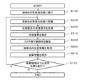
図11は、本実施例に係るオフライン処理の信号取得フロー例を示した工程図である。S100からS300までの受信信号を取得するステップは、図5で示した処理と同じであるので、説明を省略する。本実施例では、ステップS300の次に、ステップS400に代えてステップS310の処理が行われる。 FIG. 11 is a process diagram illustrating a signal acquisition flow example of offline processing according to the present embodiment. The steps of acquiring the received signals from S100 to S300 are the same as the processing shown in FIG. In this embodiment, after step S300, the process of step S310 is performed instead of step S400.
ステップS310においては、ステップS300において取得された受信信号を、記憶部720に記憶する。実施例1のステップS400とは異なり、ここでは機能情報の取得は行わないでよい。
ステップS500およびS600の処理は、図5で示した処理と同様であるため、説明を省略する。
In step S310, the reception signal acquired in step S300 is stored in
The processing in steps S500 and S600 is the same as the processing shown in FIG.
本実施例においては、ステップS600に引き続いてステップS610の処理が行われる。ステップS610では、被検体の位置情報を記憶部720に保存する。
その後、ステップS710において、移動領域内での測定繰り返すか否かの判定を行い、移動領域内に測定が済んでいない場合には、ステップ200に戻る。移動領域内での測定を繰り返さないと判定すると、測定を終了する。
測定が終了した後、繰り返し実行されたステップS310、S610にて記憶部720に記憶された信号を用いて、情報処理装置700がオフライン処理を実行する。
In the present embodiment, the process of step S610 is performed subsequent to step S600. In step S610, the position information of the subject is stored in the
Thereafter, in step S710, it is determined whether or not the measurement in the moving region is repeated. If the measurement has not been completed in the moving region, the process returns to step 200. If it is determined that the measurement in the moving area is not repeated, the measurement is terminated.
After the measurement is completed, the
図12は、本実施例に係るオフライン処理の信号処理フローを示した工程図である。本実施例では、情報処理装置700によって信号処理が行われる場合を説明する。ただし、信号処理は、光音響装置が有する情報処理装置700によって行うことに限らず、光音響装置とは別に設けられたコンピュータによって行っても良い。GPUを複数実装したコンピュータを使うと、処理速度の高速化に有利である。
FIG. 12 is a process diagram illustrating a signal processing flow of offline processing according to the present embodiment. In this embodiment, a case where signal processing is performed by the
図11で示したフローに従って保存された、被検体Eから伝搬した音響波に基づく受信信号と位置情報とを用いて、ボリュームデータが生成されるまでの処理を説明する。ボリュームデータを生成する範囲は、ユーザーが入力部を介して指定しても良いし、情報処理装置700が所定の判断に基づいて指定しても良い。
ステップS101では、指定した範囲のオフライン処理を開始する。
ステップS201は、画像再構成アルゴリズムに従って演算する演算領域の所定位置を決めるステップである。
A process until volume data is generated will be described using a reception signal based on an acoustic wave propagated from the subject E and position information stored according to the flow shown in FIG. The range in which the volume data is generated may be specified by the user via the input unit, or may be specified by the
In step S101, offline processing in the designated range is started.
Step S201 is a step of determining a predetermined position of the calculation area to be calculated according to the image reconstruction algorithm.
ステップS301では、ステップS201において定められた所定位置に対して、信号処理に必要な複数の測定個所の受信信号を読み出す。ステップS401では、複数の受信信号を取得した際の被検体Eの位置情報を読み出す。
ステップS501は、受信信号を処理して演算領域内の機能情報を算出するステップである。このステップで、受信信号の測定時の被検体Eの位置のずれの補正も同時に行うことにより、信号処理の位置誤差を低減できる。位置ずれの補正の具体的な一例として、被検体Eと保持部1100や音響マッチング材との界面を踏まえて、音速を補正する手法が挙げられる。
In step S301, received signals at a plurality of measurement locations necessary for signal processing are read out from the predetermined position determined in step S201. In step S401, the position information of the subject E when a plurality of reception signals are acquired is read out.
Step S501 is a step of processing the received signal and calculating function information in the calculation area. In this step, the position error of the signal processing can be reduced by simultaneously correcting the deviation of the position of the subject E during the measurement of the received signal. As a specific example of the correction of the positional deviation, there is a method of correcting the sound speed based on the interface between the subject E and the
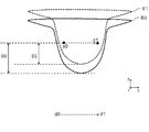
図13は、S501における位置補正について説明する図であり、タイミングt0からt1の間の位置変化を示す。符号d0,d1はそれぞれ、タイミングt0,t1における探触子位置である。複数の変換素子300がある場合、半球面の中心を探触子位置とみなしてもよい。符号c0,c1はそれぞれ、タイミングt0,t1における高感度領域Gの中心の位置である。またE0,E1は、タイミングt0とt1の間で体動により被検体位
置がずれた様子を示す。
FIG. 13 is a diagram for explaining the position correction in S501, and shows a change in position between timings t0 and t1. Reference numerals d0 and d1 denote probe positions at timings t0 and t1, respectively. When there are a plurality of
探触子位置がd0からd1に平行移動することにより、高感度領域Gの中心点もc0からc1に平行移動する。ここで、タイミングt0においては、点c0は被検体の先端からD0の深さに位置していた。一方、体動のため、被検体がz軸の正方向に移動したため、タイミングt1においては、点c1は、被検体の先端からD1の深さに位置することになる。つまり、高感度領域は、体動により、被検体のより浅い位置に移動している。一般的に音響マッチング液の音速は生体の音速よりも速いため、タイミングt1とt2では、音響信号が伝搬されるまでの時間が異なる。その結果、画像再構成の際に適切でない電気信号を抽出することになり、機能情報の算出精度を低下させる原因となってしまう。 When the probe position is translated from d0 to d1, the center point of the high sensitivity region G is also translated from c0 to c1. Here, at the timing t0, the point c0 is located at a depth D0 from the tip of the subject. On the other hand, since the subject has moved in the positive z-axis direction due to body movement, the point c1 is located at a depth D1 from the tip of the subject at timing t1. That is, the high sensitivity region has moved to a shallower position of the subject due to body movement. Generally, since the sound speed of the acoustic matching liquid is faster than the sound speed of the living body, the time until the sound signal is propagated is different at the timings t1 and t2. As a result, an unsuitable electrical signal is extracted at the time of image reconstruction, which causes a decrease in the calculation accuracy of function information.
また、被検体Eの位置の変動は、受信信号の遅延時間、変換素子の指向性に起因する感度の変動、変換素子から被検体Eまでに充填されている音響マッチング材800を通過する距離の変動、などの影響を引き起こす。これらの影響について検討する。まず、感度の変動については、信号のゲインを調整することが可能である。また、音響マッチング材800の通過距離については、体動の距離が分かれば、音響波の経路上における生体部分と音響マッチング液部分それぞれの距離を取得できるので、補正可能である。
The variation in the position of the subject E includes the delay time of the received signal, the variation in sensitivity due to the directivity of the conversion element, and the distance passing through the
ステップS601では、所定位置での機能情報を重ね合わせてボリュームデータが生成される。ステップS701は、指定した範囲の演算処理を繰り返すかどうかを判断する工程である。指定した範囲内の演算処理が済んでいないと判断された場合にはステップS201に戻り、処理を繰り返す。指定した範囲内の演算処理が済んでいると判断した場合には、ステップS801に進む。ステップS801でオフライン処理が終了し、指定した範囲のボリュームデータが出力される。このボリュームデータは、画像として、ディスプレイ900に表示されたり、記憶部720に記憶されたりする。
In step S601, volume data is generated by superimposing function information at predetermined positions. Step S701 is a step of determining whether or not to repeat the specified range of arithmetic processing. If it is determined that the arithmetic processing within the specified range has not been completed, the process returns to step S201 to repeat the processing. If it is determined that the arithmetic processing within the specified range has been completed, the process proceeds to step S801. In step S801, offline processing ends, and volume data in the specified range is output. The volume data is displayed as an image on the
なお、指定した範囲内で設定する演算領域は、データ取得時に図6で示したスパイラル形状に沿った領域に限定されない。例えば、XY方向に直行した四角形で構成することや、複数の半径の異なる円で構成することも可能である。 Note that the calculation area set within the specified range is not limited to the area along the spiral shape shown in FIG. 6 at the time of data acquisition. For example, it may be configured by a quadrangle that is orthogonal to the XY direction, or may be configured by a plurality of circles having different radii.
本実施例によれば、複数回の受信信号を位置補正して、画像再構成アルゴリズムの信号処理を実施する際に、被検体内の目標点から各変換素子に音響波が到達するまでの遅延時間、変換素子の感度、音速の少なくとも一つのパラメータを補正出来る。その結果、生成される機能情報の精度が向上する。 According to the present embodiment, when the position of the received signal is corrected multiple times and the signal processing of the image reconstruction algorithm is performed, the delay until the acoustic wave reaches each conversion element from the target point in the subject. At least one parameter of time, sensitivity of the conversion element, and sound speed can be corrected. As a result, the accuracy of the generated function information is improved.
[実施例5]
本発明の別の実施例を説明する。本実施例においては、被検体情報取得装置が、2つのモードを選択的に実行できる。第1のモードは、実施例1で説明したように、1回の光照射に基づいて得られた電気信号から生成されたボリュームデータを位置情報に基づいて補正するモードである。第2のモードは、実施例4で説明したように、複数の相対位置で得られた電気信号を位置情報に基づいて補正しながらボリュームデータを生成するモードである。
[Example 5]
Another embodiment of the present invention will be described. In this embodiment, the subject information acquisition apparatus can selectively execute two modes. As described in the first embodiment, the first mode is a mode in which volume data generated from an electrical signal obtained based on a single light irradiation is corrected based on position information. As described in the fourth embodiment, the second mode is a mode for generating volume data while correcting electric signals obtained at a plurality of relative positions based on position information.
本実施例における被検体情報取得装置は、第1のモードによる動作を行うことで、光音響測定を行いながら、被検体の位置ずれが補正されたボリュームデータの画像を随時更新していく。そして、指定された測定範囲の測定が終了すると、第2のモードによる動作を行う。つまり、第1のモードによる動作を通じて記憶部に記憶された受信信号に対して、各受信信号が得られた際の被検体Eの位置情報に基づいて、位置ずれの補正を行って、ボリュームデータを得る。こうして得られたボリュームデータは、表示部に表示される。 The subject information acquisition apparatus according to the present embodiment performs an operation in the first mode, and updates the volume data image in which the subject positional deviation is corrected while performing photoacoustic measurement. Then, when the measurement of the designated measurement range is completed, the operation in the second mode is performed. That is, the position data is corrected based on the position information of the subject E when each received signal is obtained for the received signal stored in the storage unit through the operation in the first mode, and the volume data Get. The volume data obtained in this way is displayed on the display unit.
本実施例によれば、被検体情報取得装置の操作者は、測定を行っている間もリアルタイムに機能情報を確認でき、測定終了後に、より精度よく位置ずれが補正された画像を確認できる。そのため、操作者にとって利便性の高い装置を実現できる。 According to the present embodiment, the operator of the subject information acquisition apparatus can check the function information in real time while performing the measurement, and can check the image whose positional deviation is corrected more accurately after the measurement is completed. Therefore, an apparatus that is highly convenient for the operator can be realized.
[その他の実施形態]
本発明は、以下の処理を実行することによっても実現される。即ち、上述した各実施形態の1以上の機能を実現するプログラムを、ネットワーク又は各種記憶媒体を介してシステム或いは装置に供給し、そのシステム或いは装置の情報処理装置における1つ以上のプロセッサがプログラムを読み出して実行する処理でも実現可能である。また、1以上の機能を実現する回路(例えば、FPGAやASIC)によっても実現可能である。
[Other Embodiments]
The present invention is also realized by executing the following processing. That is, a program that realizes one or more functions of the above-described embodiments is supplied to a system or apparatus via a network or various storage media, and one or more processors in the information processing apparatus of the system or apparatus execute the program. It can also be realized by processing to read and execute. It can also be realized by a circuit (for example, FPGA or ASIC) that realizes one or more functions.
100:光源,300:変換素子,400:支持体,500:走査部
600:カメラ部,700:情報処理装置
100: light source, 300: conversion element, 400: support, 500: scanning unit 600: camera unit, 700: information processing apparatus
Claims (11)
前記光が被検体に照射されることにより発生する音響波を受信して電気信号を出力する複数の変換素子と、
前記複数の変換素子を支持する支持体と、
前記支持体に設けられ、前記被検体の画像を取得する撮像部と、
前記被検体と前記支持体との相対位置を変化させる走査部と、
前記被検体と前記支持体との第一の相対位置において取得された電気信号に基づいて、前記被検体内部の第一の特性情報を取得するとともに、前記第一の相対位置とは異なる、前記被検体と前記支持体との第二の相対位置において取得された電気信号に基づいて、前記被検体内部の第二の特性情報を取得する特性情報取得手段と、
前記第一の特性情報と前記第二の特性情報との間の、前記被検体内における位置ずれを、前記被検体の位置情報に基づいて補正する補正手段と、
を有することを特徴とする被検体情報取得装置。 A light source that generates light;
A plurality of conversion elements for receiving an acoustic wave generated by irradiating the subject with the light and outputting an electrical signal;
A support that supports the plurality of conversion elements;
An imaging unit provided on the support and acquiring an image of the subject;
A scanning unit that changes a relative position between the subject and the support;
Based on the electrical signal acquired at the first relative position between the subject and the support, the first characteristic information inside the subject is obtained, and different from the first relative position, Characteristic information acquisition means for acquiring second characteristic information inside the object based on an electrical signal acquired at a second relative position between the object and the support;
Correction means for correcting a positional shift in the subject between the first characteristic information and the second characteristic information based on the positional information of the subject;
A subject information acquisition apparatus characterized by comprising:
ことを特徴とする請求項1に記載の被検体情報取得装置。 The subject information acquisition apparatus according to claim 1, wherein the position information is information representing a body movement of the subject.
ことを特徴とする請求項1または2に記載の被検体情報取得装置。 The object information acquiring apparatus according to claim 1, wherein an acoustic matching material is disposed between the support and the object.
ことを特徴とする請求項1ないし3のいずれか1項に記載の被検体情報取得装置。 4. The image capturing unit according to claim 1, wherein the imaging unit acquires the position information by comparing feature points of the subject between the images obtained at each of the plurality of relative positions. 5. 2. The subject information acquisition apparatus according to item 1.
ことを特徴とする請求項4に記載の被検体情報取得装置。 The subject information acquisition apparatus according to claim 4, wherein the feature point is a marker or a characteristic structure of the subject.
前記特性情報取得手段は、それぞれの前記相対位置において前記高感度領域で得られた前記特性情報の重ね合わせを行う
ことを特徴とする請求項1ないし5のいずれか1項に記載の被検体情報取得装置。 The conversion element is formed on the support so that a high-sensitivity region in which characteristic information inside the subject can be obtained with high accuracy is formed in a region where reception directions of at least some of the conversion elements gather. Arranged,
6. The object information according to claim 1, wherein the characteristic information acquisition unit superimposes the characteristic information obtained in the high sensitivity region at each of the relative positions. Acquisition device.
ことを特徴とする請求項6に記載の被検体情報取得装置。 The object information acquisition apparatus according to claim 6, wherein the characteristic information acquisition unit performs correction based on the position information of the object at the time of the superposition.
ことを特徴とする請求項1ないし7のいずれか1項に記載の被検体情報取得装置。 The subject according to any one of claims 1 to 7, wherein the support is a hemispherical container, and the imaging unit is at least one camera disposed on a pole of the hemisphere. Information acquisition device.
前記光が被検体に照射されることにより発生する音響波を受信して電気信号を出力する複数の変換素子と、
前記複数の変換素子を支持する、前記被検体と間隔をおいて配置された支持体と、
前記支持体に設けられ、前記被検体の外観の画像を取得する撮像部と、
前記被検体と前記支持体との相対位置を変化させる走査を行う走査部と、
前記走査中における複数の前記相対位置において、前記撮像部が取得する前記画像に基づいて、前記被検体の位置情報を取得する位置情報取得手段と、
前記電気信号および前記位置情報に基づいて前記被検体内部の特性情報を取得する特性情報取得手段と、
を有することを特徴とする被検体情報取得装置。 A light source that generates light;
A plurality of conversion elements for receiving an acoustic wave generated by irradiating the subject with the light and outputting an electrical signal;
A support body that supports the plurality of conversion elements and is spaced from the subject;
An imaging unit that is provided on the support and acquires an image of the appearance of the subject;
A scanning unit that performs scanning to change a relative position between the subject and the support;
Position information acquisition means for acquiring position information of the subject based on the image acquired by the imaging unit at the plurality of relative positions during the scanning;
Characteristic information acquisition means for acquiring characteristic information inside the subject based on the electrical signal and the position information;
A subject information acquisition apparatus characterized by comprising:
ことを特徴とする請求項1ないし9のいずれか1項に記載の被検体情報取得装置。 The object information acquiring apparatus according to claim 1, wherein the object information acquiring apparatus can operate in a mode in which the electric signals obtained at a plurality of the relative positions are corrected.
ことを特徴とする請求項10に記載の被検体情報取得装置。 The correction for the electrical signal is correction of at least one parameter among a delay time of the acoustic wave, a sensitivity of the conversion element, and a sound velocity of the acoustic wave. Sample information acquisition device.
Priority Applications (1)
| Application Number | Priority Date | Filing Date | Title |
|---|---|---|---|
| US15/235,255 US10408934B2 (en) | 2015-08-19 | 2016-08-12 | Object information acquiring apparatus |
Applications Claiming Priority (2)
| Application Number | Priority Date | Filing Date | Title |
|---|---|---|---|
| JP2015162132 | 2015-08-19 | ||
| JP2015162132 | 2015-08-19 |
Publications (2)
| Publication Number | Publication Date |
|---|---|
| JP2017038917A true JP2017038917A (en) | 2017-02-23 |
| JP2017038917A5 JP2017038917A5 (en) | 2019-07-04 |
Family
ID=58205915
Family Applications (1)
| Application Number | Title | Priority Date | Filing Date |
|---|---|---|---|
| JP2016116259A Pending JP2017038917A (en) | 2015-08-19 | 2016-06-10 | Subject information acquisition device |
Country Status (1)
| Country | Link |
|---|---|
| JP (1) | JP2017038917A (en) |
Cited By (4)
| Publication number | Priority date | Publication date | Assignee | Title |
|---|---|---|---|---|
| JP2019000469A (en) * | 2017-06-16 | 2019-01-10 | キヤノン株式会社 | Subject information acquisition apparatus |
| JP2019187514A (en) * | 2018-04-18 | 2019-10-31 | キヤノン株式会社 | Subject information acquisition device, subject information processing method and program |
| DE102021205598A1 (en) | 2020-06-18 | 2021-12-23 | Advantest Corporation | ULTRASONIC OPTICAL WAVE MEASURING DEVICE, METHOD, PROGRAM, AND STORAGE MEDIUM |
| JP2022140651A (en) * | 2018-04-18 | 2022-09-26 | キヤノン株式会社 | Subject information acquisition device, subject information processing method and program |
Citations (6)
| Publication number | Priority date | Publication date | Assignee | Title |
|---|---|---|---|---|
| US20110306865A1 (en) * | 2008-09-10 | 2011-12-15 | Endra, Inc. | photoacoustic imaging device |
| JP2012040038A (en) * | 2010-08-12 | 2012-03-01 | Canon Inc | Photoacoustic wave measuring device |
| JP2012147858A (en) * | 2011-01-17 | 2012-08-09 | Tokyo Univ Of Agriculture & Technology | Image processor, image processing method, and image processing program |
| JP2012196308A (en) * | 2011-03-22 | 2012-10-18 | Fujifilm Corp | Apparatus and method for photoacoustic imaging |
| US20150119680A1 (en) * | 2013-10-31 | 2015-04-30 | Canon Kabushiki Kaisha | Subject information obtaining apparatus |
| JP2015083219A (en) * | 2015-01-08 | 2015-04-30 | キヤノン株式会社 | Subject information acquisition device and control method for subject information acquisition device |
-
2016
- 2016-06-10 JP JP2016116259A patent/JP2017038917A/en active Pending
Patent Citations (7)
| Publication number | Priority date | Publication date | Assignee | Title |
|---|---|---|---|---|
| US20110306865A1 (en) * | 2008-09-10 | 2011-12-15 | Endra, Inc. | photoacoustic imaging device |
| JP2012040038A (en) * | 2010-08-12 | 2012-03-01 | Canon Inc | Photoacoustic wave measuring device |
| JP2012147858A (en) * | 2011-01-17 | 2012-08-09 | Tokyo Univ Of Agriculture & Technology | Image processor, image processing method, and image processing program |
| JP2012196308A (en) * | 2011-03-22 | 2012-10-18 | Fujifilm Corp | Apparatus and method for photoacoustic imaging |
| US20150119680A1 (en) * | 2013-10-31 | 2015-04-30 | Canon Kabushiki Kaisha | Subject information obtaining apparatus |
| JP2015109947A (en) * | 2013-10-31 | 2015-06-18 | キヤノン株式会社 | Subject information acquisition apparatus |
| JP2015083219A (en) * | 2015-01-08 | 2015-04-30 | キヤノン株式会社 | Subject information acquisition device and control method for subject information acquisition device |
Cited By (8)
| Publication number | Priority date | Publication date | Assignee | Title |
|---|---|---|---|---|
| JP2019000469A (en) * | 2017-06-16 | 2019-01-10 | キヤノン株式会社 | Subject information acquisition apparatus |
| US11723539B2 (en) | 2017-06-16 | 2023-08-15 | Canon Kabushiki Kaisha | Photoacoustic subject information acquisition apparatus for imaging a subject by moving probe to circulate along a common circulating path |
| JP2019187514A (en) * | 2018-04-18 | 2019-10-31 | キヤノン株式会社 | Subject information acquisition device, subject information processing method and program |
| JP7118718B2 (en) | 2018-04-18 | 2022-08-16 | キヤノン株式会社 | SUBJECT INFORMATION ACQUISITION APPARATUS, SUBJECT INFORMATION PROGRAM, AND PROGRAM |
| JP2022140651A (en) * | 2018-04-18 | 2022-09-26 | キヤノン株式会社 | Subject information acquisition device, subject information processing method and program |
| JP7314371B2 (en) | 2018-04-18 | 2023-07-25 | キヤノン株式会社 | SUBJECT INFORMATION ACQUISITION APPARATUS, SUBJECT INFORMATION PROGRAM, AND PROGRAM |
| DE102021205598A1 (en) | 2020-06-18 | 2021-12-23 | Advantest Corporation | ULTRASONIC OPTICAL WAVE MEASURING DEVICE, METHOD, PROGRAM, AND STORAGE MEDIUM |
| US11982646B2 (en) | 2020-06-18 | 2024-05-14 | Advantest Corporation | Optical ultrasonic wave measuring apparatus, method, and storage medium |
Similar Documents
| Publication | Publication Date | Title |
|---|---|---|
| US10408934B2 (en) | Object information acquiring apparatus | |
| JP5939786B2 (en) | Acoustic wave acquisition device | |
| KR102054382B1 (en) | Object information acquiring apparatus and control method thereof | |
| JP6486068B2 (en) | Test site information acquisition device | |
| JP6272191B2 (en) | Subject information acquisition device | |
| JP6632257B2 (en) | Subject information acquisition device | |
| KR101937065B1 (en) | Object information acquiring apparatus | |
| WO2016076244A1 (en) | Object information acquiring apparatus | |
| JP6472437B2 (en) | Photoacoustic apparatus and acoustic wave receiving apparatus | |
| EP2957221A1 (en) | Object information acquiring apparatus | |
| JP2017038917A (en) | Subject information acquisition device | |
| JP2017521104A (en) | Photoacoustic device | |
| JP6742745B2 (en) | Information acquisition device and display method | |
| JP2016529061A (en) | Photoacoustic device | |
| US20170265750A1 (en) | Information processing system and display control method | |
| US20170325692A1 (en) | Acoustic wave receiving apparatus | |
| KR101899838B1 (en) | Photoacoustic apparatus and information acquisition apparatus | |
| JP2017196026A (en) | Subject information acquisition device | |
| EP3329843B1 (en) | Display control apparatus, display control method, and program | |
| JP2018061725A (en) | Subject information acquisition device and signal processing method | |
| US10492694B2 (en) | Object information acquisition apparatus | |
| JP2019165836A (en) | Subject information acquisition device, and control method therefor | |
| JP2018061716A (en) | Information processing device, information processing method, and program | |
| US20170265749A1 (en) | Processing apparatus and processing method | |
| JP2017202313A (en) | Acoustic wave reception device |
Legal Events
| Date | Code | Title | Description |
|---|---|---|---|
| RD02 | Notification of acceptance of power of attorney |
Free format text: JAPANESE INTERMEDIATE CODE: A7422 Effective date: 20181116 |
|
| A521 | Request for written amendment filed |
Free format text: JAPANESE INTERMEDIATE CODE: A523 Effective date: 20190528 |
|
| A621 | Written request for application examination |
Free format text: JAPANESE INTERMEDIATE CODE: A621 Effective date: 20190528 |
|
| A977 | Report on retrieval |
Free format text: JAPANESE INTERMEDIATE CODE: A971007 Effective date: 20200528 |
|
| A131 | Notification of reasons for refusal |
Free format text: JAPANESE INTERMEDIATE CODE: A131 Effective date: 20200616 |
|
| A02 | Decision of refusal |
Free format text: JAPANESE INTERMEDIATE CODE: A02 Effective date: 20201222 |