EP2554115B1 - Apparatus and method for acquiring information on subject - Google Patents
Apparatus and method for acquiring information on subject Download PDFInfo
- Publication number
- EP2554115B1 EP2554115B1 EP12176834.5A EP12176834A EP2554115B1 EP 2554115 B1 EP2554115 B1 EP 2554115B1 EP 12176834 A EP12176834 A EP 12176834A EP 2554115 B1 EP2554115 B1 EP 2554115B1
- Authority
- EP
- European Patent Office
- Prior art keywords
- wavelength
- subject
- light
- attenuation coefficient
- effective attenuation
- Prior art date
- Legal status (The legal status is an assumption and is not a legal conclusion. Google has not performed a legal analysis and makes no representation as to the accuracy of the status listed.)
- Not-in-force
Links
Images


Classifications
-
- A—HUMAN NECESSITIES
- A61—MEDICAL OR VETERINARY SCIENCE; HYGIENE
- A61B—DIAGNOSIS; SURGERY; IDENTIFICATION
- A61B5/00—Measuring for diagnostic purposes; Identification of persons
- A61B5/0093—Detecting, measuring or recording by applying one single type of energy and measuring its conversion into another type of energy
- A61B5/0095—Detecting, measuring or recording by applying one single type of energy and measuring its conversion into another type of energy by applying light and detecting acoustic waves, i.e. photoacoustic measurements
-
- A—HUMAN NECESSITIES
- A61—MEDICAL OR VETERINARY SCIENCE; HYGIENE
- A61B—DIAGNOSIS; SURGERY; IDENTIFICATION
- A61B5/00—Measuring for diagnostic purposes; Identification of persons
- A61B5/145—Measuring characteristics of blood in vivo, e.g. gas concentration, pH value; Measuring characteristics of body fluids or tissues, e.g. interstitial fluid, cerebral tissue
- A61B5/1455—Measuring characteristics of blood in vivo, e.g. gas concentration, pH value; Measuring characteristics of body fluids or tissues, e.g. interstitial fluid, cerebral tissue using optical sensors, e.g. spectral photometrical oximeters
- A61B5/14551—Measuring characteristics of blood in vivo, e.g. gas concentration, pH value; Measuring characteristics of body fluids or tissues, e.g. interstitial fluid, cerebral tissue using optical sensors, e.g. spectral photometrical oximeters for measuring blood gases
Definitions
- the present invention relates to an apparatus and method for acquiring information such as a spectral characteristic of a subject by detecting an acoustic wave generated in a subject.
- Photoacoustic tomography is attracting attention as a technique to obtain an image uniquely representing a new blood vessel formed by cancer.
- the PAT is a technique to illuminate a subject with a pulsed light (a near infrared ray), detect a photoacoustic wave generated by the subject with an acoustic wave detector, and convert the detected photoacoustic wave into an image.
- a pulsed light a near infrared ray
- Equation (1) The initial pressure P 0 of the photoacoustic wave generated in a region of interest of the subject can be expressed by Equation (1) shown below.
- P 0 ⁇ ⁇ ⁇ a ⁇ ⁇
- ⁇ is a Gruneisen coefficient which is obtained by dividing the product of the coefficient of volume expansion ⁇ and the square of the sound speed c by the specific heat C p . It is known that when a subject is given, ⁇ takes a substantially constant value for the given object.
- ⁇ a is an absorption coefficient of a region of interest
- ⁇ is the light intensity in the region of interest (the light intensity of light illuminating the region of interest, which is also called light fluence).
- the photoacoustic wave generated in the subject propagates through the subject and is detected by an acoustic wave detector put on the surface of the subject. Based on a detection result, a signal processing apparatus acquires an initial pressure distribution P 0 by using a reconstruction method such as a back projection method or the like.
- Equation (1) by dividing the initial pressure distribution P 0 by the Gruneisen coefficient ⁇ , the distribution of the product of ⁇ a and ⁇ , i.e., an optical energy density distribution is obtained. Furthermore, an absorption coefficient distribution ⁇ a (r) can be obtained by dividing the optical energy density distribution by the light intensity distribution ⁇ (r) in the subject.
- NPL 1 Functional Photoacoustic tomography for non-invasive imaging of cerebral blood oxygenation and blood volume in rat brain in vivo
- ⁇ HbO (mm -1 M -1 ) denote the molar absorption coefficient of oxyhemoglobin
- ⁇ Hb (mm -1 M -1 ) denote the molar absorption coefficient of deoxyhemoglobin.
- the molar absorption coefficient refers to an absorption coefficient for a sample including 1 mol hemoglobin per 1 liter. The value of the molar absorption coefficient is uniquely determined by the wavelength.
- Equation (2) the absorption coefficient ⁇ a of blood at the wavelength ⁇ 1 and that at the wavelength ⁇ 2 are given by Equation (2) shown below.
- the,absorption coefficient ⁇ a of blood at each wavelength is given by the sum of the product of the molar absorption coefficient ⁇ HbO of oxyhemoglobin and the molar concentration C HbO of oxyhemoglobin and the product of the molar absorption coefficient ⁇ Hb of deoxyhemoglobin and the molar concentration C Hb of deoxyhemoglobin.
- Equation (2) can be rewritten as described below in Equation (3).
- ⁇ C HbO ⁇ Hb ⁇ 1 ⁇ ⁇ a ⁇ 2 - ⁇ Hb ⁇ 2 ⁇ ⁇ a ⁇ 1 ⁇ Hb ⁇ 1 ⁇ ⁇ HbO ⁇ 2 - ⁇ HbO ⁇ 1 ⁇ ⁇ Hb ⁇ 2
- C Hb ⁇ Hb ⁇ 1 ⁇ ⁇ a ⁇ 2 - ⁇ HbO ⁇ 2 ⁇ ⁇ a ⁇ 1 ⁇ HbO ⁇ 1 ⁇ ⁇ Hb ⁇ 2 - ⁇ Hb ⁇ 1 ⁇ ⁇ Hb ⁇ 2
- the oxygen saturation StO 2 is the ratio of oxyhemoglobin to the total hemoglobin, and thus it can be determined from Equation (3) as expressed in Equation (4) shown below.
- NPL 1 it is assumed that the light intensity constantly attenuates in a direction from a surface illuminated pulsed light to a target. Based on this assumption, the light intensity at the target is calculated, and the absorption coefficient of the target is determined using the calculated light intensity.
- Japanese Patent Laid-Open No. 2010-88627 discloses a technique of acquiring an absorption coefficient using a light intensity distribution acquired taking into account the shape of a subject.
- the light intensity distribution obtained in this manner is more accurate than that according to NPL 1.
- an embodiment provides a subject information acquisition apparatus capable of acquiring subject information with a less number of steps of acquiring a light intensity distribution.
- the present invention provides a subject information acquisition apparatus as specified in claim 1.
- the present invention also provides a method of acquiring subject information as specified in claim 10.
- the present invention also provides a program as specified in claim 18. Preferred embodiments are defined in the dependent claims.
- Fig. 1 illustrates a subject information acquisition apparatus according to the present embodiment.
- the subject information acquisition apparatus includes, as basic hardware components, a light source 100, an illumination optical system 200 serving as an illumination optical unit, an acoustic wave detector 400 serving as an acoustic wave detection unit, a signal processing apparatus 500 serving as a signal processing unit, and a spectrum acquisition apparatus 700 serving as a spectrum acquisition unit.
- the light source 100 is configured to generate light with a first wavelength ⁇ 1 and light with a second wavelength ⁇ 2 .
- Pulsed light 110 with the first wavelength emitted from the light source 100 is passed through the illumination optical system 200 and resultant illumination light 210 illuminates a subject 300.
- a light absorber 310 in the subject 300 absorbs the illumination light 210 and generates a photoacoustic wave 311.
- the acoustic wave detector 400 detects the photoacoustic wave and converts it into a first detection signal in the form of an electric signal.
- the acoustic wave detector 400 detects a photoacoustic wave 311 generated by illuminating the subject 300 with illumination light 210 with the second wavelength and the acoustic wave detector 400 converts it into a second detection signal in the form of an electric signal.
- the signal processing apparatus 500 acquires an oxygen saturation distribution in the subject 300 based on the first detection signal and the second detection signal.
- the resultant oxygen saturation is displayed on a monitor 600.
- the subject information acquisition apparatus also includes a spectrum acquisition apparatus 700 configured to acquire an effective attenuation coefficient spectrum of the subject 300. Based on the effective attenuation coefficient spectrum of the subject 300 acquired by the spectrum acquisition apparatus 700, the signal processing apparatus 500 selects the first wavelength and the second wavelength such that the same effective attenuation coefficient is obtained at these two wavelengths.
- the average attenuation coefficient in the subject 300 is used as the effective attenuation coefficient.
- the subject information may include other information in addition to the oxygen saturation determined based on absorption coefficients at a plurality of wavelengths.
- FIG. 2 is a flow chart illustrating the subject information acquisition method according to the present embodiment. Note that step numbers used in the following description correspond to step numbers shown in Fig. 2 .
- the spectrum acquisition apparatus 700 acquires the effective attenuation coefficient spectrum of the subject 300 shown in Fig. 3 .
- the effective attenuation coefficient spectrum may be represented by a graph in which the wavelength is plotted horizontally and the effective attenuation coefficient ⁇ eff is plotted vertically. Note that the term "effective attenuation coefficient spectrum" may also be used to describe a set of data representing the graph described above.
- the signal processing apparatus 500 selects two wavelengths at which the same effective attenuation coefficient is obtained.
- the two wavelengths at which the same effective attenuation coefficient is obtained may be arbitrary two wavelengths as long as effective attenuation coefficients at these two wavelengths satisfy the requirement of the present embodiment, i.e., it is sufficient if the effective attenuation coefficients are substantially equal to each other.
- the signal processing apparatus 500 may select wavelengths at which low effective attenuation coefficients are obtained.
- wavelengths may be selected in a range from 650 nm to 900 nm, which is called a "living body window" because light with a wavelength in this range can easily pass through a living body.
- the two wavelengths ⁇ 1 and ⁇ 2 may be selected such that the ratio of the absorption coefficient at a location of a blood vessel or cancer between the two wavelengths ⁇ 1 and ⁇ 2 , i.e., ⁇ a ( ⁇ 1 )/ ⁇ a ( ⁇ 2 ), changes as much as possible with a change in the oxygen saturation.
- the signal processing apparatus 500 may select the wavelengths ⁇ 1 and ⁇ 2 such that
- a Ti:Sa laser, an alexandrite laser, or the like may be used as for the laser used in the PAT.
- the Ti:Sa laser provides a maximum output power in a range around 800 nm
- the alexandrite laser provides a maximum output power in a range around 755 nm.
- the signal processing apparatus 500 may select wavelengths in a range from 700 to 850 nm including the above-described ranges in which the respective lasers have their maximum output power.
- the signal processing apparatus 500 may select the first wavelength in a range of 756 to 761 nm corresponding to a peak at 756 nm of deoxyhemoglobin and a peak at 761 nm of fat.
- the signal processing apparatus 500 may select the second wavelength in a range of 830 to 840 nm corresponding to a peak at 830 nm of fat and a peak at 840 nm of water.
- the two wavelengths at which the effective attenuation coefficient is equal may be defined as follows.
- the oxygen saturation of an artery is typically 99%, and the oxygen saturation of a vein is typically 80%.
- a paper titled " Combined diffuse optical spectroscopy and contrast-enhanced magnetic resonance imaging for monitoring breast cancer neoadjuvant chemotherapy: a case study” (Natasha Shah, Jessica Gibbs, Dulcy Wolverton, Albert Cerussi, Nola Hylton, Bruce J Tromberg, Journal of Biomedical Optics (2005) Volume: 10, Issue: 5, Pages: 051503 )
- the oxygen saturation of a new blood vessel generated by a tumor can be estimated as 66%. Therefore, if the error of the oxygen saturation is within a range of ⁇ 10%, it is possible to distinguish between a new blood vessel and a normal blood vessel.
- the two wavelengths at which the effective attenuation coefficient is equal may be selected from a range in which the error of the oxygen saturation calculated for a particular measurement depth is within ⁇ 10%.
- wavelengths may be selected such that the error of the oxygen saturation is less than ⁇ 10%.
- each light absorber has an oxygen saturation in a range from 50 to 100%, the difference in oxygen saturation between any two light absorbers is 10% at most, and the subject has an effective attenuation coefficient of 0.09233 mm -1 in a wavelength range of 756 nm to 797 nm.
- Equation (4) indicates that a necessary difference in the effective attenuation coefficient between the two wavelengths is ⁇ 0.003 mm -1 .
- the light intensity ⁇ (d) in the subject is determined according to a one-dimensional model shown below in Equation (5), where ⁇ 0 is the light intensity incident on the subject, ⁇ eff is the effective attenuation coefficient of the subject, and d is the measurement depth.
- ⁇ d ⁇ 0 ⁇ exp - ⁇ eff ⁇ d
- a necessary effective attenuation coefficient for the second wavelength is 0.09233 ⁇ 0.003 mm -1 . That is, when 756 nm is selected as the first wavelength, the second wavelength is not limited to exactly 797 nm as long as it is possible to distinguish between absorbers with oxygen saturations that are different by 10%.
- the two wavelengths with the same effective attenuation coefficient do not necessarily need to be exactly equal in the effective attenuation coefficient, but two wavelengths may be regarded as having equal effective attenuation coefficients if the two wavelengths allow it to distinguish between a normal blood vessel and a new blood vessel produced by a tumor.
- two wavelengths may be regarded as being equal in effective attenuation coefficient if these two wavelengths allow it to distinguish between absorbers having oxygen saturations different by 10%.
- the effective attenuation coefficient spectrum acquired in step S101 may be displayed on the monitor 600 such that a user is allowed to select two wavelengths, which give the same effective attenuation coefficient, from the displayed effective attenuation coefficient spectrum.
- the signal processing apparatus 500 may select three wavelengths at which the effective attenuation coefficient is equal to a particular value denoted by reference numeral 610.
- three wavelengths 656 nm, 755 nm, and 823 nm are selected.
- four or more wavelengths may be selected at which effective attenuation coefficients are equal, if such a selection is possible.
- the signal processing apparatus 500 may select a first pair of wavelengths with a particular effective attenuation coefficient value 610 and may further select a second pair of wavelengths with another effective attenuation coefficient value different from the effective attenuation coefficient value 610.
- any method may be employed to select wavelengths from an effective attenuation coefficient spectrum as long as it is possible to select wavelengths at which effective attenuation coefficients are equal.
- the light source 100 generates pulsed light 110 with the two wavelengths selected in step S102.
- the pulsed light 110 is guided by the illumination optical system 200 such that the illumination light 210 strikes the subject 300.
- the acoustic wave detector 400 detects a photoacoustic wave 311 generated by the illumination of light with the respective wavelengths.
- the acoustic wave detector 400 detects a photoacoustic wave generated by illuminating the subject 300 with the light with the first wavelength and output an electric signal as a first detection signal, and the acoustic wave detector 400 detects a photoacoustic wave generated by illuminating the subject 300 with the light with the second wavelength and output an electric signal as a second detection signal.
- the signal processing apparatus 500 acquires, as subject information, an oxygen saturation distribution in the subject 300.
- the signal processing apparatus 500 performs an image reconstruction based on the first detection signal and acquires a first initial pressure distribution P 0 ( ⁇ 1 , r) in the subject 300. Similarly, the signal processing apparatus 500 performs an image reconstruction based on the second detection signal and acquires a second initial pressure distribution P 0 ( ⁇ 2 , r) in the subject 300.
- Equation (6) the initial pressure distribution obtained in the above-described manner can be expressed as in Equation (6) shown below.
- ⁇ P 0 ⁇ 1 r ⁇ ⁇ ⁇ a ⁇ 1 r ⁇ ⁇ ⁇ 1 r
- P 0 ⁇ 2 r ⁇ ⁇ ⁇ a ⁇ 2 r ⁇ ⁇ ⁇ 2 r
- the initial pressure distribution P 0 is given by the product of the Gruneisen coefficient ⁇ , the absorption coefficient distribution ⁇ a in the subject 300, and the light intensity distribution ⁇ in the subject 300.
- the two wavelengths are selected such that the same effective attenuation coefficient of the subject 300 is obtained at these two wavelengths, and thus the same light intensity distribution in the subject 300 is obtained for both wavelengths.
- Equation (7) represents the oxygen saturation.
- StO 2 r - P 0 ⁇ 1 r ⁇ ⁇ Hb ⁇ 2 + P 0 ⁇ 2 r ⁇ ⁇ Hb ⁇ 1 - P 0 ⁇ 1 r ⁇ Hb ⁇ 2 - ⁇ HbO ⁇ 2 + P 0 ⁇ 2 r ⁇ Hb ⁇ 1 - ⁇ HbO ⁇ 1
- the signal processing apparatus 500 is capable of calculating the oxygen saturation only from the initial pressure without using the light intensity distribution. That is, in the subject information acquisition method according to the present embodiment, it is allowed to remove the process of acquiring the light intensity in the process of acquiring the oxygen saturation.
- the signal processing apparatus 500 may first determine the initial pressure at respective points in the subject 300 based on the first detection signal and the second detection signal, and then may acquire the oxygen saturation at the respective points from the initial pressure at the points, and may finally acquire the oxygen saturation distribution.
- the signal processing apparatus 500 may acquire the oxygen saturation based on the detection signal using a method other than the method of calculating the oxygen saturation other than Equation (7). For example, based on the detection signal, the signal processing apparatus 500 may retrieve an oxygen saturation from an oxygen saturation data table stored in advance in a memory of the signal processing apparatus 500 whereby the signal processing apparatus 500 may acquire the oxygen saturation.
- the signal processing apparatus 500 may be implemented on a computer, and a program including the process described above may be executed by the computer.
- the subject information acquisition apparatus it is possible to remove measurement equipment for acquiring the light intensity, and thus it is possible to reduce the total apparatus size. Furthermore, it is possible to reduce the error in the measurement for determining the absorption coefficient, and thus it is possible to obtain more accurate oxygen saturation.
- the light source 100 may be configured to generate pulsed light with a pulse width of 5 nsec to 50 nsec. To make it possible to determine the oxygen saturation distribution at a depth of a several ten mm, the output power of the light source 100 may be a few mJ/pulse or greater.
- a high-power laser or light emitting diode may be used as the light source 100.
- the laser many types of lasers such as a solid-state laser, a gas laser, a dye laser, a semiconductor laser, etc. may be employed. More specifically, for example, a Ti:Sa laser pumped by Nd:YAG, an alexandrite laser, or the like capable of outputting high power and capable of continuously changing the wavelength may be used.
- the light source 100 may be realized by a combination of a plurality of single-wavelength lasers with different wavelengths.
- the light source 100 may include a first light source configured to generate light with the first wavelength and a second light source configured to generate light with the second wavelength.
- the illumination optical system 200 is an optical system that guides pulsed light generated by the light source 100 such that the pulsed light strikes, as illumination light 210, the subject 300.
- the illumination optical system 200 may include a light reflection mirror, a half mirror that splits the light into reference light and illumination light, a lens that focuses the light, enlarges the light, or change the shape of the light, a diffusion plate that expands light, etc.
- the illumination light 210 may be expanded by a lens so as to have a proper cross-sectional area.
- the illumination light 210 may be converted by a diffusion plane, a fly-eye lens, or the like into light with a smooth light intensity distribution.
- the illumination optical system 200 may be configured to illuminate the subject 300 with the illumination light 210 such that the illumination light 210 provides the same optical pattern for all wavelengths used.
- output ends of element fibers of the bundle fiber may be arranged at random with respect to the incident ends such that an equal optical pattern is obtained for any wavelength.
- the illumination area of the illumination light 210 may move on the subject 300. By moving the illumination area such that light illuminates the subject 300 in an overlapping manner, it is possible to obtain a uniform light intensity distribution over the surface of the subject. This situation is equivalent to the situation in which the subject is illuminated with two light rays having different wavelengths and having equal light intensity distributions.
- the illumination area on the subject 300 may be moved by using a movable mirror or by mechanically moving the light source itself.
- the illumination light 210 may strike the subject 300 from the side of the acoustic wave detector 400 or from the opposite side.
- the illumination light 210 may strike both sides of the subject 300.
- the acoustic wave detector 400 is configured to detect a photoacoustic wave 311 generated by the light absorber 310.
- a transduce using a piezoelectric effect, a transducer using resonance of light, a transduce using a change in capacitance, or the like may be used.
- any other type of transduce may be used as the acoustic wave detector as long as it is capable of detecting photoacoustic waves.
- the transducer may be of an array type or a single-element type.
- the acoustic wave detector 400 may be installed at a fixed location to detect the photoacoustic wave or may be installed such that the acoustic wave detector 400 is scanned along the subject 300. Alternatively, the acoustic wave detector 400 may be moved around the subject 300 to detect photoacoustic waves at various points.
- the signal processing apparatus 500 is an apparatus configured to acquire subject information based on the detection signal supplied from the acoustic wave detector 400.
- the signal processing apparatus 500 may amplify the detection signal supplied from the acoustic wave detector 400 and may convert the amplified detection signal from an analog signal into a digital signal.
- detection signal is used to describe both the analog signal output from the acoustic wave detector 400 and the digital signal converted from the analog signal.
- the signal processing apparatus 500 further acquires an optical characteristic value distribution in the subject by reconstructing an image based on the detection signal.
- the signal processing apparatus 500 is typically a workstation or the like configured to execute software including a program prepared in advance in terms of the image reconstruction process and the like.
- inverse projection in time domain or Fourier domain may be used, which is widely used in tomography techniques.
- the signal processing apparatus 500 may employ an image reconstruction method including iterative processing based on inverse problem analysis or the like.
- an acoustic wave detector including an acoustic lens or the like, it becomes possible for the signal processing apparatus 500 to acquire an initial pressure distribution in the subject without performing the image reconstruction.
- the signal processing apparatus 500 may be configured to simultaneously process the plurality of signals such that forming an image is complete for a shorter time.
- the signal processing apparatus 500 may be realized by a combination of separate apparatuses such as an amplifier, an analog-to-digital converter, an FPGA (Field Programmable Gate Array) chip, etc.
- the signal processing described above may be implemented in a program, and the signal processing apparatus 500 may execute the program to perform the signal processing.
- the spectrum acquisition apparatus 700 is an apparatus configured to acquire an effective attenuation coefficient spectrum associated with the subject 300.
- DOS diffuse optical spectroscopy
- DOS is a technique of illuminating a subject with light, detecting light propagating and diffusing in the subject with a photodetector, and obtaining optical constants (absorption coefficient ⁇ a and reduced scattering coefficient ⁇ s ') of the subject from a light detection signal.
- the DOS apparatus solve an inverse problem of the light propagation on the light detection signal detected by the photodetector, and calculates the average absorption coefficient ⁇ a and reduced scattering coefficient ⁇ s ' of the subject.
- the DOS apparatus evaluates the similarity, by means of fitting, of the calculated absorption coefficient and reduced scattering coefficient with respect to known absorption coefficient spectra of fat, water, oxyhemoglobin, deoxyhemoglobin, etc.
- the DOS apparatus determines a component ratio of the subject based on the result of fitting. Using the obtained component ratio of the subject, the DOS apparatus acquires an effective attenuation coefficient spectrum of the subject according to Equation (8).
- ⁇ eff 3 ⁇ ⁇ a ⁇ ⁇ s ⁇ + ⁇ a
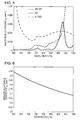
- Fig. 6 shows a typical reduced scattering coefficient spectrum of a human breast.
- the DOS apparatus acquires an effective attenuation coefficient spectrum from Equation (8) such as that shown in Fig. 3 .
- optical constant distributions an absorption coefficient distribution and a scattering coefficient distribution
- optical constant distributions in the subject may be acquired using diffuse optical tomography (DOT) or the like, and an average attenuation coefficient in an arbitrary region of the subject may be employed as the effective attenuation coefficient.
- DOT diffuse optical tomography
- the spectrum acquisition apparatus 700 may be disposed in the subject information acquisition apparatus according to the present embodiment or may be disposed separately from the subject information acquisition apparatus. For example, based on a light detection signal obtained using a photodetector provided separated from the subject information acquisition apparatus, the signal processing apparatus 500 may acquire the effective attenuation coefficient spectrum of the subject 300.
- the spectrum acquisition apparatus 700 may acquire the effective attenuation coefficient spectrum by estimating the component ratio of the subject based on information on subject such as an age, a height, a weight, a body fat percentage, etc.
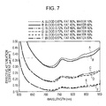
- Fig. 7 shows effective attenuation coefficient spectra A to F for different subjects having various component ratios, wherein these effective attenuation coefficient spectra are determined by simulation for various values of component ratios of fat (40 to 80%), water (10 to 50%) and blood (0.57 to 0.87%). Note that in the simulation, the oxygen saturation of the blood is fixed to 75%.
- the spectrum acquisition apparatus 700 may acquire an effective attenuation coefficient spectrum for each subject.
- the spectrum acquisition apparatus 700 may select an effective attenuation coefficient spectrum for each subject from data of a plurality of effective attenuation coefficient spectra.
- FIG. 8 is a diagram illustrating a configuration of a subject information acquisition apparatus according to the second embodiment.
- elements similar to those in Fig. 1 are denoted by similar reference numerals and a further description thereof is omitted.
- the present embodiment is different from the first embodiment in that a photodetector 900 is additionally provided as a photodetector unit configured to detect light illuminating the subject 300. Furthermore, in the present embodiment, the signal processing apparatus 500 acquires an oxygen saturation of the subject 300 based on the light intensity acquired by the photodetector 900.
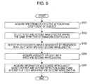
- Fig. 9 is a flow chart illustrating a subject information acquisition method according to the present embodiment. A further description of processing steps similar to those shown in Fig. 2 is omitted.
- the photodetector 900 detects the light with the first wavelength and the light with the second wavelength and acquires the intensity of the light with the first wavelength and that with the second wavelength.
- pulsed light 110 is split by a measurement optical system 800 and directed to the photodetector 900.
- the measurement optical system 800 may direct illumination light 210, instead of the pulsed light 110, to the photodetector 900.
- the measurement optical system 800 may direct all or part of the light to the photodetector 900.
- the signal processing apparatus 500 may acquire the total light intensity of the illumination light 210 based on the light split ratio and the detected light intensity.
- the signal processing apparatus 500 may take into account an influence of the illumination optical system 200 on the light intensity.
- the measurement optical system 800 a total reflection mirror, a separate mirror, a bundle fiber, or the like may be employed.
- the measurement optical system 800 may be realized by a combination of two or more of the above elements.
- the illumination optical system 200 may be used also as the measurement optical system 800.
- the photodetector 900 is an optical power meter, and an optical sensor using a photodiode, a thermal sensor using a thermocouple, a pyroelectric sensor using a pyroelectric material, or the like may be used. In particular, when short pulse light is used, a pyroelectric sensor may be used as the photodetector 900.
- the signal processing apparatus 500 acquires oxygen saturation based on the first detection signal and the second detection signal acquired in step S103 and the intensity of the light with the first wavelength and the intensity of the light with the second wavelength acquired in step S204.
- A( ⁇ ) denote the light intensity (surface light intensity) of the surface of the subject
- ⁇ r ( ⁇ , r) denote the light intensity distribution in the subject expressed in relative value assuming that the light intensity on the surface of the subject is equal to 1, wherein ⁇ r ( ⁇ , r) is called a relative light intensity distribution.
- the same illumination optical system 200 is used for all wavelengths, and thus it is assumed that the optical pattern is identical for all wavelengths, that is, the relative light intensity distribution is identical for all wavelengths.
- the initial pressure is given by Equation (10).
- ⁇ P 0 ⁇ 1 r ⁇ ⁇ ⁇ a ⁇ 1 r ⁇ A ⁇ 1 ⁇ ⁇ r r
- P 0 ⁇ 2 r ⁇ ⁇ ⁇ a ⁇ 2 r ⁇ A ⁇ 2 ⁇ ⁇ r r
- Equation (11) represents the oxygen saturation.
- StO 2 r / A ⁇ 1 - P 0 ⁇ 1 r ⁇ Hb ⁇ 2 + / A ⁇ 2 P 0 ⁇ 2 r ⁇ Hb ⁇ 1 / A ⁇ 1 - P 0 ⁇ 1 r ⁇ Hb ⁇ 2 - ⁇ HbO ⁇ 2 + / A ⁇ 2 P 0 ⁇ 2 r ⁇ Hb ⁇ 1 - ⁇ HbO ⁇ 1
- the signal processing apparatus 500 is capable of determining the oxygen saturation from the light intensity acquired in step S204 and the detection signal acquired in step S103.
- the subject information acquisition method allows it to acquire the oxygen saturation without acquiring the light intensity distribution in the subject even in a case where there is a difference in intensity between the two light rays with different wavelengths striking the subject 300. Therefore, in the present embodiment, it is allowed to remove the process of acquiring the light intensity distribution from the process of determining the oxygen saturation.
- the signal processing apparatus 500 may be implemented on a computer, and a program including the process described above may be executed by the computer.
- FIG. 10 is a flow chart illustrating a subject information acquisition method according to the third embodiment. In the following description, processing steps similar to those shown in Fig. 2 or Fig. 9 are omitted.
- the signal processing apparatus 500 serving as the control unit controls the intensity of the light with the first wavelength and the intensity of the light with the second wavelength based on the intensity of light acquired in step S204 so as to minimize the difference between the intensity of the light with first wavelength and the intensity of the light with the second wavelength.
- the controlling of the light intensity is performed by the signal processing apparatus 500 by controlling the output of the light source 100.
- the signal processing apparatus 500 may control the illumination optical system 200 to control the light intensity. More specifically, for example, the signal processing apparatus 500 may control an optical filter in the illumination optical system 200 so as to control the intensity of light with the respective wavelengths. Note that the signal processing apparatus 500 may correct the light intensity for either one of light beams or for both light beams.
- another different apparatus may control the output of the light source 100 or the illumination optical system 200.
- control is performed such that the difference in light intensity between the two wavelengths is minimized, and thus the difference in light intensity distribution in the subject between the two wavelengths is also minimized.
- the signal processing apparatus 500 may be implemented on a computer, and a program including the process described above may be executed by the computer.
- a light source (100) is capable of generating light with a first wavelength and alight with a second wavelength different from the first wavelength
- an acoustic wave detection unit (400) detects a photoacoustic wave generated by illuminating a subject with light and output a resultant detection signal
- a signal processing unit (500) acquires subject information based on a first detection signal output by the acoustic wave detection unit when the subject is illuminated with the light with the first wavelength and a second detection signal output by the acoustic wave detection unit when the subject is illuminated with the light with the second wavelength.
- An effective attenuation coefficient of the subject at the first wavelength is equal to an effective attenuation coefficient of the subject at the second wavelength.
Description
- The present invention relates to an apparatus and method for acquiring information such as a spectral characteristic of a subject by detecting an acoustic wave generated in a subject.
- Photoacoustic tomography is attracting attention as a technique to obtain an image uniquely representing a new blood vessel formed by cancer. The PAT is a technique to illuminate a subject with a pulsed light (a near infrared ray), detect a photoacoustic wave generated by the subject with an acoustic wave detector, and convert the detected photoacoustic wave into an image.
- The initial pressure P0 of the photoacoustic wave generated in a region of interest of the subject can be expressed by Equation (1) shown below.

In this Equation, Γ is a Gruneisen coefficient which is obtained by dividing the product of the coefficient of volume expansion β and the square of the sound speed c by the specific heat Cp. It is known that when a subject is given, Γ takes a substantially constant value for the given object. µa is an absorption coefficient of a region of interest, Φ is the light intensity in the region of interest (the light intensity of light illuminating the region of interest, which is also called light fluence). - The photoacoustic wave generated in the subject propagates through the subject and is detected by an acoustic wave detector put on the surface of the subject. Based on a detection result, a signal processing apparatus acquires an initial pressure distribution P0 by using a reconstruction method such as a back projection method or the like.
- From Equation (1), by dividing the initial pressure distribution P0 by the Gruneisen coefficient Γ, the distribution of the product of µa and Φ, i.e., an optical energy density distribution is obtained. Furthermore, an absorption coefficient distribution µa(r) can be obtained by dividing the optical energy density distribution by the light intensity distribution Φ(r) in the subject.
- In a paper, "Functional Photoacoustic tomography for non-invasive imaging of cerebral blood oxygenation and blood volume in rat brain in vivo" (X. Wang, L. V. Wang et al. Proc. of SPIE Vol. 5697 (2005) (hereinafter referred to as NPL 1), a technique is disclosed to calculate an oxygen saturation distribution using two absorption coefficient distributions obtained for light with two wavelengths.
- Let εHbO (mm-1M-1) denote the molar absorption coefficient of oxyhemoglobin, and εHb (mm-1M-1) denote the molar absorption coefficient of deoxyhemoglobin. Note that the molar absorption coefficient refers to an absorption coefficient for a sample including 1 mol hemoglobin per 1 liter. The value of the molar absorption coefficient is uniquely determined by the wavelength.
- Furthermore, let CHbO denote the molar concentration (M) of oxyhemoglobin, and CHb denote the molar concentration (M) of deoxyhemoglobin. When parameters are given as described above, the absorption coefficient µa of blood at the wavelength λ1 and that at the wavelength λ2 are given by Equation (2) shown below.

- As can be seen, the,absorption coefficient µa of blood at each wavelength is given by the sum of the product of the molar absorption coefficient εHbO of oxyhemoglobin and the molar concentration CHbO of oxyhemoglobin and the product of the molar absorption coefficient εHb of deoxyhemoglobin and the molar concentration CHb of deoxyhemoglobin.
- Equation (2) can be rewritten as described below in Equation (3).

- The oxygen saturation StO2 is the ratio of oxyhemoglobin to the total hemoglobin, and thus it can be determined from Equation (3) as expressed in Equation (4) shown below.

- That is, if the absorption coefficient µa of the blood at the wavelength λ1 and that at the wavelength λ2 are given, then all values are known and thus the oxygen saturation can be calculated from Equation (4).
- In
NPL 1, it is assumed that the light intensity constantly attenuates in a direction from a surface illuminated pulsed light to a target. Based on this assumption, the light intensity at the target is calculated, and the absorption coefficient of the target is determined using the calculated light intensity. - Japanese Patent Laid-Open No.
2010-88627 NPL 1. - Prior art which is related to this field of technology can be found in e.g. document
US 2007/0232911 A1 disclosing a device for photodetecting tumor, in non-patent literature Min Qu et. al., Proceedings of the SPIE - The International Society for Optical Engineering SPIE, vol. 7564, 2010, disclosing a combined photoacoustic and magneto-motive ultrasound imaging, and in documentUS 7 515 948 B1 disclosing a photoacoustic analyzer of region of interest in a human body. - By applying the technique of acquiring the absorption coefficient disclosed in
PTL 1 to the technique of acquiring the oxygen saturation disclosed inNPL 1, it becomes possible to acquire the oxygen saturation with better accuracy. - However, although the technique disclosed in
PTL 1 allows it to acquire the light intensity distribution with better accuracy, it needs an additional process for acquiring the light intensity distribution. - In view of the above, an embodiment provides a subject information acquisition apparatus capable of acquiring subject information with a less number of steps of acquiring a light intensity distribution.
- The present invention provides a subject information acquisition apparatus as specified in
claim 1. - The present invention also provides a method of acquiring subject information as specified in
claim 10. - The present invention also provides a program as specified in claim 18. Preferred embodiments are defined in the dependent claims.
- Further features of the present invention will become apparent from the following description of exemplary embodiments with reference to the attached drawings.
-
-
Fig. 1 is a diagram illustrating a subject information acquisition apparatus according to a first embodiment. -
Fig. 2 is a flow chart illustrating a subject information acquisition method according to the first embodiment. -
Fig. 3 is a diagram illustrating an effective attenuation coefficient spectrum of a subject according to the first embodiment. -
Fig. 4 is a diagram illustrating a monitor display screen according to the first embodiment. -
Fig. 5 is a diagram illustrating absorption coefficient spectra of components of a subject according to the first embodiment. -
Fig. 6 is a diagram illustrating a reduced scattering coefficient spectrum of a subject according to the first embodiment. -
Fig. 7 is a diagram illustrating effective attenuation coefficient spectra of various objects with different component ratios under examination. -
Fig. 8 is a diagram illustrating a subject information acquisition apparatus according to a second embodiment. -
Fig. 9 is a flow chart illustrating a subject information acquisition method according to the second embodiment. -
Fig. 10 is a flow chart illustrating a subject information acquisition method according to a third embodiment. - An embodiment of a subject information acquisition apparatus is described below in detail with reference to drawings.
-
Fig. 1 illustrates a subject information acquisition apparatus according to the present embodiment. - The subject information acquisition apparatus according to the present embodiment includes, as basic hardware components, a
light source 100, an illuminationoptical system 200 serving as an illumination optical unit, anacoustic wave detector 400 serving as an acoustic wave detection unit, asignal processing apparatus 500 serving as a signal processing unit, and aspectrum acquisition apparatus 700 serving as a spectrum acquisition unit. Thelight source 100 is configured to generate light with a first wavelength λ1 and light with a second wavelength λ2. - Pulsed
light 110 with the first wavelength emitted from thelight source 100 is passed through the illuminationoptical system 200 andresultant illumination light 210 illuminates asubject 300. A light absorber 310 in thesubject 300 absorbs theillumination light 210 and generates a photoacoustic wave 311. Theacoustic wave detector 400 detects the photoacoustic wave and converts it into a first detection signal in the form of an electric signal. - Similarly, the
acoustic wave detector 400 detects a photoacoustic wave 311 generated by illuminating thesubject 300 withillumination light 210 with the second wavelength and theacoustic wave detector 400 converts it into a second detection signal in the form of an electric signal. - Next, the
signal processing apparatus 500 acquires an oxygen saturation distribution in thesubject 300 based on the first detection signal and the second detection signal. The resultant oxygen saturation is displayed on amonitor 600. - Furthermore, in the present embodiment, the subject information acquisition apparatus also includes a
spectrum acquisition apparatus 700 configured to acquire an effective attenuation coefficient spectrum of the subject 300. Based on the effective attenuation coefficient spectrum of the subject 300 acquired by thespectrum acquisition apparatus 700, thesignal processing apparatus 500 selects the first wavelength and the second wavelength such that the same effective attenuation coefficient is obtained at these two wavelengths. - As described above, by acquiring the oxygen saturation using light with the first wavelength and light with the second wavelength at which the same effective attenuation coefficient is obtained, it becomes possible to reduce the number of steps of acquiring the light intensity.
- Note that in the present embodiment, the average attenuation coefficient in the subject 300 is used as the effective attenuation coefficient. Furthermore, in the present embodiment, the subject information may include other information in addition to the oxygen saturation determined based on absorption coefficients at a plurality of wavelengths.
- Next, a subject information acquisition method according to the present embodiment is described below.
- Referring to
Fig. 1 andFig. 2 , the subject information acquisition method according to the present embodiment is described below.Fig. 2 is a flow chart illustrating the subject information acquisition method according to the present embodiment. Note that step numbers used in the following description correspond to step numbers shown inFig. 2 . - S101: Step of acquiring effective attenuation coefficient spectrum of subject
- In this step, the
spectrum acquisition apparatus 700 acquires the effective attenuation coefficient spectrum of the subject 300 shown inFig. 3 . The effective attenuation coefficient spectrum may be represented by a graph in which the wavelength is plotted horizontally and the effective attenuation coefficient µeff is plotted vertically. Note that the term "effective attenuation coefficient spectrum" may also be used to describe a set of data representing the graph described above. InFig. 3 , an effective attenuation coefficient spectrum is plotted for aparticular subject 300 having a component ratio fat = 66% : water = 20% : blood = 0.7% (oxygen saturation = 80%). - S102: Step of selecting first wavelength and second wavelength at which the same effective attenuation coefficient is obtained
- In this step, based on the effective attenuation coefficient spectrum acquired in step S101, the
signal processing apparatus 500 selects two wavelengths at which the same effective attenuation coefficient is obtained. Note that in the present embodiment, the two wavelengths at which the same effective attenuation coefficient is obtained may be arbitrary two wavelengths as long as effective attenuation coefficients at these two wavelengths satisfy the requirement of the present embodiment, i.e., it is sufficient if the effective attenuation coefficients are substantially equal to each other. - In a case where the subject 300 is a living body, when it is desired to observe deep points thereof, the
signal processing apparatus 500 may select wavelengths at which low effective attenuation coefficients are obtained. For example, wavelengths may be selected in a range from 650 nm to 900 nm, which is called a "living body window" because light with a wavelength in this range can easily pass through a living body. - Furthermore, taking into account a measurement error or measurement noise, the two wavelengths λ1 and λ2 may be selected such that the ratio of the absorption coefficient at a location of a blood vessel or cancer between the two wavelengths λ1 and λ2, i.e., µa(λ1)/µa(λ2), changes as much as possible with a change in the oxygen saturation. More specifically, for example, when the molar absorption coefficient of deoxyhemoglobin at the wavelength λ1 is given by εHb(λ1) and that at the wavelength λ2 is given by εHb(λ2), and the molar absorption coefficient of oxyhemoglobin at the wavelength λ1 is given by εHbO(λ1) and that at the wavelength λ2 is given by εHbO(λ2), then the
signal processing apparatus 500 may select the wavelengths λ1 and λ2 such that |(εHbO(λ1) - εHb(λ1) - (εHbO(λ2) - εHb(λ2))| is maximized. - As for the laser used in the PAT, a Ti:Sa laser, an alexandrite laser, or the like may be used. The Ti:Sa laser provides a maximum output power in a range around 800 nm, while the alexandrite laser provides a maximum output power in a range around 755 nm. The
signal processing apparatus 500 may select wavelengths in a range from 700 to 850 nm including the above-described ranges in which the respective lasers have their maximum output power. For example, thesignal processing apparatus 500 may select the first wavelength in a range of 756 to 761 nm corresponding to a peak at 756 nm of deoxyhemoglobin and a peak at 761 nm of fat. Thesignal processing apparatus 500 may select the second wavelength in a range of 830 to 840 nm corresponding to a peak at 830 nm of fat and a peak at 840 nm of water. - The two wavelengths at which the effective attenuation coefficient is equal may be defined as follows.
- The oxygen saturation of an artery is typically 99%, and the oxygen saturation of a vein is typically 80%. According to a paper titled "Combined diffuse optical spectroscopy and contrast-enhanced magnetic resonance imaging for monitoring breast cancer neoadjuvant chemotherapy: a case study" (Natasha Shah, Jessica Gibbs, Dulcy Wolverton, Albert Cerussi, Nola Hylton, Bruce J Tromberg, Journal of Biomedical Optics (2005) Volume: 10, Issue: 5, Pages: 051503), the oxygen saturation of a new blood vessel generated by a tumor can be estimated as 66%. Therefore, if the error of the oxygen saturation is within a range of ±10%, it is possible to distinguish between a new blood vessel and a normal blood vessel. That is, the two wavelengths at which the effective attenuation coefficient is equal may be selected from a range in which the error of the oxygen saturation calculated for a particular measurement depth is within ±10%. To calculate the oxygen saturation with better accuracy, wavelengths may be selected such that the error of the oxygen saturation is less than ±10%.
- In the following discussion, let it be assumed, by way of example, that the subject has a plurality of light absorbers located at
depths 0 to 30 mm. Let it be further assumed that each light absorber has an oxygen saturation in a range from 50 to 100%, the difference in oxygen saturation between any two light absorbers is 10% at most, and the subject has an effective attenuation coefficient of 0.09233 mm-1 in a wavelength range of 756 nm to 797 nm. - In such a situation, to distinguish among the absorbers, Equation (4) indicates that a necessary difference in the effective attenuation coefficient between the two wavelengths is ±0.003 mm-1. The light intensity Φ(d) in the subject is determined according to a one-dimensional model shown below in Equation (5), where Φ0 is the light intensity incident on the subject, µeff is the effective attenuation coefficient of the subject, and d is the measurement depth.

- From the above discussion, it can be seen that when 756 nm is selected as the first wavelength, a necessary effective attenuation coefficient for the second wavelength is 0.09233 ± 0.003 mm-1. That is, when 756 nm is selected as the first wavelength, the second wavelength is not limited to exactly 797 nm as long as it is possible to distinguish between absorbers with oxygen saturations that are different by 10%.
- That is, in the present embodiment, the two wavelengths with the same effective attenuation coefficient do not necessarily need to be exactly equal in the effective attenuation coefficient, but two wavelengths may be regarded as having equal effective attenuation coefficients if the two wavelengths allow it to distinguish between a normal blood vessel and a new blood vessel produced by a tumor. For example, as in the present embodiment, two wavelengths may be regarded as being equal in effective attenuation coefficient if these two wavelengths allow it to distinguish between absorbers having oxygen saturations different by 10%.
- As shown in
Fig. 4 , the effective attenuation coefficient spectrum acquired in step S101 may be displayed on themonitor 600 such that a user is allowed to select two wavelengths, which give the same effective attenuation coefficient, from the displayed effective attenuation coefficient spectrum. - In the above-described example, two wavelengths are selected such that equal effective attenuation coefficients are obtained at the two wavelengths. Alternatively, as shown in
Fig. 4 , thesignal processing apparatus 500 may select three wavelengths at which the effective attenuation coefficient is equal to a particular value denoted byreference numeral 610. In the example shown inFig. 4 , threewavelengths 656 nm, 755 nm, and 823 nm are selected. Note that in the present embodiment, four or more wavelengths may be selected at which effective attenuation coefficients are equal, if such a selection is possible. - Still alternatively, the
signal processing apparatus 500 may select a first pair of wavelengths with a particular effectiveattenuation coefficient value 610 and may further select a second pair of wavelengths with another effective attenuation coefficient value different from the effectiveattenuation coefficient value 610. - Note that any method may be employed to select wavelengths from an effective attenuation coefficient spectrum as long as it is possible to select wavelengths at which effective attenuation coefficients are equal.
- S103: Step of detecting photoacoustic wave generated by illumination of light with first and second wavelengths
- In this step, the
light source 100 generates pulsed light 110 with the two wavelengths selected in step S102. Thepulsed light 110 is guided by the illuminationoptical system 200 such that theillumination light 210 strikes the subject 300. Theacoustic wave detector 400 detects a photoacoustic wave 311 generated by the illumination of light with the respective wavelengths. - More specifically, in the present embodiment, the
acoustic wave detector 400 detects a photoacoustic wave generated by illuminating the subject 300 with the light with the first wavelength and output an electric signal as a first detection signal, and theacoustic wave detector 400 detects a photoacoustic wave generated by illuminating the subject 300 with the light with the second wavelength and output an electric signal as a second detection signal. - S104: Step of acquiring subject information based on first and second detection signals
- In this step, based on the first detection signal and the second detection signal acquired in step S103, the
signal processing apparatus 500 acquires, as subject information, an oxygen saturation distribution in the subject 300. - More specifically, first, the
signal processing apparatus 500 performs an image reconstruction based on the first detection signal and acquires a first initial pressure distribution P0(λ1, r) in the subject 300. Similarly, thesignal processing apparatus 500 performs an image reconstruction based on the second detection signal and acquires a second initial pressure distribution P0(λ2, r) in the subject 300. - From Equation (1), the initial pressure distribution obtained in the above-described manner can be expressed as in Equation (6) shown below.

- That is, the initial pressure distribution P0 is given by the product of the Gruneisen coefficient Γ, the absorption coefficient distribution µa in the subject 300, and the light intensity distribution Φ in the subject 300.
- In the present embodiment, the two wavelengths are selected such that the same effective attenuation coefficient of the subject 300 is obtained at these two wavelengths, and thus the same light intensity distribution in the subject 300 is obtained for both wavelengths.
- Since the same light intensity distribution is obtained for both wavelengths, by applying the initial pressure in Equation (6) to Equation (4), Equation (7) is obtained which represents the oxygen saturation.

- From Equation (7), the
signal processing apparatus 500 is capable of calculating the oxygen saturation only from the initial pressure without using the light intensity distribution. That is, in the subject information acquisition method according to the present embodiment, it is allowed to remove the process of acquiring the light intensity in the process of acquiring the oxygen saturation. - Note that the
signal processing apparatus 500 may first determine the initial pressure at respective points in the subject 300 based on the first detection signal and the second detection signal, and then may acquire the oxygen saturation at the respective points from the initial pressure at the points, and may finally acquire the oxygen saturation distribution. - In the present embodiment, the
signal processing apparatus 500 may acquire the oxygen saturation based on the detection signal using a method other than the method of calculating the oxygen saturation other than Equation (7). For example, based on the detection signal, thesignal processing apparatus 500 may retrieve an oxygen saturation from an oxygen saturation data table stored in advance in a memory of thesignal processing apparatus 500 whereby thesignal processing apparatus 500 may acquire the oxygen saturation. - The
signal processing apparatus 500 may be implemented on a computer, and a program including the process described above may be executed by the computer. - It is possible to acquire the oxygen saturation by performing the process described above without using the light intensity, and thus the process of acquiring the light intensity is no longer necessary unlike in other known techniques. Therefore, in the subject information acquisition apparatus according to the present embodiment, it is possible to remove measurement equipment for acquiring the light intensity, and thus it is possible to reduce the total apparatus size. Furthermore, it is possible to reduce the error in the measurement for determining the absorption coefficient, and thus it is possible to obtain more accurate oxygen saturation.
- Furthermore, in the present embodiment, it is possible to acquire accurate oxygen saturation even in a case where it is difficult to measure the illumination light distribution or the shape of the subject or even in a case where it is difficult to define the shape by the subject by a holding plate or the like.
- A specific example of a configuration of the present embodiment is described below. Light source
- The
light source 100 may be configured to generate pulsed light with a pulse width of 5 nsec to 50 nsec. To make it possible to determine the oxygen saturation distribution at a depth of a several ten mm, the output power of thelight source 100 may be a few mJ/pulse or greater. A high-power laser or light emitting diode may be used as thelight source 100. As for the laser, many types of lasers such as a solid-state laser, a gas laser, a dye laser, a semiconductor laser, etc. may be employed. More specifically, for example, a Ti:Sa laser pumped by Nd:YAG, an alexandrite laser, or the like capable of outputting high power and capable of continuously changing the wavelength may be used. - The
light source 100 may be realized by a combination of a plurality of single-wavelength lasers with different wavelengths. For example, thelight source 100 may include a first light source configured to generate light with the first wavelength and a second light source configured to generate light with the second wavelength. - The illumination
optical system 200 is an optical system that guides pulsed light generated by thelight source 100 such that the pulsed light strikes, asillumination light 210, the subject 300. For example, the illuminationoptical system 200 may include a light reflection mirror, a half mirror that splits the light into reference light and illumination light, a lens that focuses the light, enlarges the light, or change the shape of the light, a diffusion plate that expands light, etc. Theillumination light 210 may be expanded by a lens so as to have a proper cross-sectional area. Theillumination light 210 may be converted by a diffusion plane, a fly-eye lens, or the like into light with a smooth light intensity distribution. - The illumination
optical system 200 may be configured to illuminate the subject 300 with theillumination light 210 such that theillumination light 210 provides the same optical pattern for all wavelengths used. In a case where a bundle fiber is used as the illuminationoptical system 200, output ends of element fibers of the bundle fiber may be arranged at random with respect to the incident ends such that an equal optical pattern is obtained for any wavelength. - The illumination area of the
illumination light 210 may move on the subject 300. By moving the illumination area such that light illuminates the subject 300 in an overlapping manner, it is possible to obtain a uniform light intensity distribution over the surface of the subject. This situation is equivalent to the situation in which the subject is illuminated with two light rays having different wavelengths and having equal light intensity distributions. The illumination area on the subject 300 may be moved by using a movable mirror or by mechanically moving the light source itself. - The
illumination light 210 may strike the subject 300 from the side of theacoustic wave detector 400 or from the opposite side. Theillumination light 210 may strike both sides of the subject 300. - The
acoustic wave detector 400 is configured to detect a photoacoustic wave 311 generated by thelight absorber 310. As for the acoustic wave detector, a transduce using a piezoelectric effect, a transducer using resonance of light, a transduce using a change in capacitance, or the like may be used. Note that any other type of transduce may be used as the acoustic wave detector as long as it is capable of detecting photoacoustic waves. The transducer may be of an array type or a single-element type. Theacoustic wave detector 400 may be installed at a fixed location to detect the photoacoustic wave or may be installed such that theacoustic wave detector 400 is scanned along the subject 300. Alternatively, theacoustic wave detector 400 may be moved around the subject 300 to detect photoacoustic waves at various points. - The
signal processing apparatus 500 is an apparatus configured to acquire subject information based on the detection signal supplied from theacoustic wave detector 400. - The
signal processing apparatus 500 may amplify the detection signal supplied from theacoustic wave detector 400 and may convert the amplified detection signal from an analog signal into a digital signal. - Note that in the present description, the term "detection signal" is used to describe both the analog signal output from the
acoustic wave detector 400 and the digital signal converted from the analog signal. - The
signal processing apparatus 500 further acquires an optical characteristic value distribution in the subject by reconstructing an image based on the detection signal. Thesignal processing apparatus 500 is typically a workstation or the like configured to execute software including a program prepared in advance in terms of the image reconstruction process and the like. - As for an image reconstruction algorithm, for example, inverse projection in time domain or Fourier domain may be used, which is widely used in tomography techniques.
- In a case where it is allowed to spend much time on the reconstruction, the
signal processing apparatus 500 may employ an image reconstruction method including iterative processing based on inverse problem analysis or the like. - By employing an acoustic wave detector including an acoustic lens or the like, it becomes possible for the
signal processing apparatus 500 to acquire an initial pressure distribution in the subject without performing the image reconstruction. - In a case where a plurality of detection signals are obtained from the
acoustic wave detector 400, thesignal processing apparatus 500 may be configured to simultaneously process the plurality of signals such that forming an image is complete for a shorter time. - The
signal processing apparatus 500 may be realized by a combination of separate apparatuses such as an amplifier, an analog-to-digital converter, an FPGA (Field Programmable Gate Array) chip, etc. - The signal processing described above may be implemented in a program, and the
signal processing apparatus 500 may execute the program to perform the signal processing. - The
spectrum acquisition apparatus 700 is an apparatus configured to acquire an effective attenuation coefficient spectrum associated with the subject 300. - As for the
spectrum acquisition apparatus 700, for example, a diffuse optical spectroscopy (DOS) apparatus may be used. - DOS is a technique of illuminating a subject with light, detecting light propagating and diffusing in the subject with a photodetector, and obtaining optical constants (absorption coefficient µa and reduced scattering coefficient µs') of the subject from a light detection signal.
- First, the DOS apparatus solve an inverse problem of the light propagation on the light detection signal detected by the photodetector, and calculates the average absorption coefficient µa and reduced scattering coefficient µs' of the subject. Next, the DOS apparatus evaluates the similarity, by means of fitting, of the calculated absorption coefficient and reduced scattering coefficient with respect to known absorption coefficient spectra of fat, water, oxyhemoglobin, deoxyhemoglobin, etc. The DOS apparatus determines a component ratio of the subject based on the result of fitting. Using the obtained component ratio of the subject, the DOS apparatus acquires an effective attenuation coefficient spectrum of the subject according to Equation (8).

- In a case where the absorption coefficient is sufficiently smaller compared with the reduced scattering coefficient, the effective attenuation coefficient can be expressed by Equation (9).

-
Fig. 5 shows absorption coefficient spectra of respective components obtained by fitting for a subject including fat (66%), water (20%), and blood (0.7%) of blood (oxygen saturation = 80%).Fig. 6 shows a typical reduced scattering coefficient spectrum of a human breast. - Thereafter, based on the absorption coefficient spectra shown in
Fig. 5 and the reduced scattering coefficient spectrum shown inFig. 6 , the DOS apparatus acquires an effective attenuation coefficient spectrum from Equation (8) such as that shown inFig. 3 . - As for a technique of the DOS measurement, time-resolved diffuse optical spectroscopy (TR-DOS) using pulsed light, frequency-resolved diffuse optical spectroscopy (FR-DOS) using modulated light, or the like may be used. In the present embodiment, any DOS measurement technique may be used to acquire the effective attenuation coefficient spectrum.
- Alternatively, optical constant distributions (an absorption coefficient distribution and a scattering coefficient distribution) in the subject may be acquired using diffuse optical tomography (DOT) or the like, and an average attenuation coefficient in an arbitrary region of the subject may be employed as the effective attenuation coefficient.
- The
spectrum acquisition apparatus 700 may be disposed in the subject information acquisition apparatus according to the present embodiment or may be disposed separately from the subject information acquisition apparatus. For example, based on a light detection signal obtained using a photodetector provided separated from the subject information acquisition apparatus, thesignal processing apparatus 500 may acquire the effective attenuation coefficient spectrum of the subject 300. - Alternatively, the
spectrum acquisition apparatus 700 may acquire the effective attenuation coefficient spectrum by estimating the component ratio of the subject based on information on subject such as an age, a height, a weight, a body fat percentage, etc. -
Fig. 7 shows effective attenuation coefficient spectra A to F for different subjects having various component ratios, wherein these effective attenuation coefficient spectra are determined by simulation for various values of component ratios of fat (40 to 80%), water (10 to 50%) and blood (0.57 to 0.87%). Note that in the simulation, the oxygen saturation of the blood is fixed to 75%. - As can be seen from
Fig. 7 , the shape of the effective attenuation coefficient spectrum varies depending on the component ratio of the subject 300. Therefore, in selection of two wavelengths at which equal effective attenuation coefficients are obtained, thespectrum acquisition apparatus 700 may acquire an effective attenuation coefficient spectrum for each subject. Alternatively, thespectrum acquisition apparatus 700 may select an effective attenuation coefficient spectrum for each subject from data of a plurality of effective attenuation coefficient spectra. - Next, referring to
Fig. 8 andFig. 9 , a second embodiment is described below.Fig. 8 is a diagram illustrating a configuration of a subject information acquisition apparatus according to the second embodiment. In this figure, elements similar to those inFig. 1 are denoted by similar reference numerals and a further description thereof is omitted. - The present embodiment is different from the first embodiment in that a
photodetector 900 is additionally provided as a photodetector unit configured to detect light illuminating the subject 300. Furthermore, in the present embodiment, thesignal processing apparatus 500 acquires an oxygen saturation of the subject 300 based on the light intensity acquired by thephotodetector 900. -
Fig. 9 is a flow chart illustrating a subject information acquisition method according to the present embodiment. A further description of processing steps similar to those shown inFig. 2 is omitted. - S204: Step of acquiring intensity of light with first wavelength and that with second wavelength
- In this step, the
photodetector 900 detects the light with the first wavelength and the light with the second wavelength and acquires the intensity of the light with the first wavelength and that with the second wavelength. - In the present embodiment, pulsed light 110 is split by a measurement
optical system 800 and directed to thephotodetector 900. - Note that the measurement
optical system 800 may directillumination light 210, instead of thepulsed light 110, to thephotodetector 900. - The measurement
optical system 800 may direct all or part of the light to thephotodetector 900. In a case where the measurementoptical system 800 directs part of the light to thephotodetector 900, thesignal processing apparatus 500 may acquire the total light intensity of theillumination light 210 based on the light split ratio and the detected light intensity. - In this process of acquiring the total light intensity of the
illumination light 210, thesignal processing apparatus 500 may take into account an influence of the illuminationoptical system 200 on the light intensity. - As for the measurement
optical system 800, a total reflection mirror, a separate mirror, a bundle fiber, or the like may be employed. The measurementoptical system 800 may be realized by a combination of two or more of the above elements. The illuminationoptical system 200 may be used also as the measurementoptical system 800. - The
photodetector 900 is an optical power meter, and an optical sensor using a photodiode, a thermal sensor using a thermocouple, a pyroelectric sensor using a pyroelectric material, or the like may be used. In particular, when short pulse light is used, a pyroelectric sensor may be used as thephotodetector 900. - S205: Step of acquiring subject information based on the first and second detection signals and intensity of light with first and second wavelengths
- In this step, the
signal processing apparatus 500 acquires oxygen saturation based on the first detection signal and the second detection signal acquired in step S103 and the intensity of the light with the first wavelength and the intensity of the light with the second wavelength acquired in step S204. - Let A(λ) denote the light intensity (surface light intensity) of the surface of the subject, and let Φr(λ, r) denote the light intensity distribution in the subject expressed in relative value assuming that the light intensity on the surface of the subject is equal to 1, wherein Φr(λ, r) is called a relative light intensity distribution. In the present embodiment, the same illumination
optical system 200 is used for all wavelengths, and thus it is assumed that the optical pattern is identical for all wavelengths, that is, the relative light intensity distribution is identical for all wavelengths. - In this situation, according to the present embodiment, the initial pressure is given by Equation (10).

- By applying the initial pressure in Equation (10) to Equation (4), Equation (11) is obtained which represents the oxygen saturation.

- Thus, according to Equation (11), the
signal processing apparatus 500 is capable of determining the oxygen saturation from the light intensity acquired in step S204 and the detection signal acquired in step S103. - Thus, the subject information acquisition method according to the present embodiment allows it to acquire the oxygen saturation without acquiring the light intensity distribution in the subject even in a case where there is a difference in intensity between the two light rays with different wavelengths striking the subject 300. Therefore, in the present embodiment, it is allowed to remove the process of acquiring the light intensity distribution from the process of determining the oxygen saturation.
- The
signal processing apparatus 500 may be implemented on a computer, and a program including the process described above may be executed by the computer. - A third embodiment is described below with reference to
Fig. 8 andFig. 10. Fig. 10 is a flow chart illustrating a subject information acquisition method according to the third embodiment. In the following description, processing steps similar to those shown inFig. 2 orFig. 9 are omitted. - S304: Step of controlling the intensity of light with the first wavelength and that with the second wavelength.
- In this step, the
signal processing apparatus 500 serving as the control unit controls the intensity of the light with the first wavelength and the intensity of the light with the second wavelength based on the intensity of light acquired in step S204 so as to minimize the difference between the intensity of the light with first wavelength and the intensity of the light with the second wavelength. - In the present embodiment, the controlling of the light intensity is performed by the
signal processing apparatus 500 by controlling the output of thelight source 100. Alternatively, thesignal processing apparatus 500 may control the illuminationoptical system 200 to control the light intensity. More specifically, for example, thesignal processing apparatus 500 may control an optical filter in the illuminationoptical system 200 so as to control the intensity of light with the respective wavelengths. Note that thesignal processing apparatus 500 may correct the light intensity for either one of light beams or for both light beams. - Instead of the
signal processing apparatus 500, another different apparatus may control the output of thelight source 100 or the illuminationoptical system 200. - In this step, the control is performed such that the difference in light intensity between the two wavelengths is minimized, and thus the difference in light intensity distribution in the subject between the two wavelengths is also minimized.
- Thus, by controlling the light intensity, it is possible to increase the accuracy of the oxygen saturation acquired in step S103 without acquiring the light intensity distribution.
- The
signal processing apparatus 500 may be implemented on a computer, and a program including the process described above may be executed by the computer. - While the present invention has been described with reference to exemplary embodiments, it is to be understood that the invention is not limited to the disclosed exemplary embodiments. The scope of the following claims is to be accorded the broadest interpretation so as to encompass all such modifications and equivalent structures and functions.
- In an apparatus arranged to acquire subject information, a light source (100) is capable of generating light with a first wavelength and alight with a second wavelength different from the first wavelength, an acoustic wave detection unit (400) detects a photoacoustic wave generated by illuminating a subject with light and output a resultant detection signal, and a signal processing unit (500) acquires subject information based on a first detection signal output by the acoustic wave detection unit when the subject is illuminated with the light with the first wavelength and a second detection signal output by the acoustic wave detection unit when the subject is illuminated with the light with the second wavelength. An effective attenuation coefficient of the subject at the first wavelength is equal to an effective attenuation coefficient of the subject at the second wavelength.
Claims (18)
- A subject information acquisition apparatus comprising:a light source (100) arranged to be capable of generating light with a first wavelength and light with a second wavelength different from the first wavelength;an acoustic wave detection unit (400) arranged to detect a photoacoustic wave generated by illuminating a subject with light and output a resultant detection signal; anda signal processing unit (500) arranged to acquire subject information based on a first detection signal output by the acoustic wave detection unit when the subject is illuminated with the light with the first wavelength and a second detection signal output by the acoustic wave detection unit when the subject is illuminated with the light with the second wavelength, characterized in thatthe signal processing unit is arranged to set the first wavelength and the second wavelength based on an effective attenuation coefficient spectrum of the subject,such that an effective attenuation coefficient of the subject at the first wavelength is substantially equal to an effective attenuation coefficient of the subject at the second wavelength.
- The subject information acquisition apparatus according to claim 1, further comprising a spectrum acquisition unit (700) arranged to acquire the effective attenuation coefficient spectrum.
- The subject information acquisition apparatus according to one of claims 1 to 2, further comprising an illumination optical unit (200) arranged to obtain optical patterns equal for both the light with the first wavelength and the light with the second wavelength.
- The subject information acquisition apparatus according to one of claims 1 to 3, further comprising:a photodetector unit (900) arranged to acquire intensity of the light with the first wavelength and intensity of the light with the second wavelength; anda control unit (500) arranged to control the intensity of the light with the first wavelength or the intensity of the light with the second wavelength based on the intensity of the light with first wavelength and the intensity of the light with second wavelength acquired by the photodetector unit so as to minimize the difference between the intensity of the light with first wavelength and the intensity of the light with the second wavelength.
- The subject information acquisition apparatus according to one of claims 1 to 4, wherein the signal processing unit is arranged to:acquire a first initial pressure distribution in the subject based on the first detection signal;acquire a second initial pressure distribution in the subject based on the second detection signal; andacquire the subject information based on the first initial pressure distribution and the second initial pressure distribution.
- The subject information acquisition apparatus according to one of claims 1 to 5, wherein the subject information is an oxygen saturation distribution in the subject.
- The subject information acquisition apparatus according to one of claims 1 to 6, the signal processing unit selects the first wavelength and the second wavelength from the effective attenuation coefficient spectrum of the subject and sets the first wavelength and the second wavelength selected by the signal processing unit.
- The subject information acquisition apparatus according to one of claims 1 to 6, further comprising a selecting means arranged so that a user is enabled to select the first wavelength and the second wavelength from the effective attenuation coefficient spectrum of the subject and to output information according to the first and second wavelengths selected by the user,
wherein the signal processing unit is arranged to set the first wavelength and the second wavelength by using the information output from the selecting means. - The subject information acquisition apparatus according to one of claims 1 to 8, wherein the signal processing unit is arranged to set the first wavelength and the second wavelength which allow it to distinguish between absorbers having oxygen saturations different by 10%.
- A method of acquiring subject information, comprising:illuminating a subject with light with a first wavelength,obtaining a first detection signal by detecting a photoacoustic wave generated by illuminating the subject with light with the first wavelength,illuminating the subject with light with a second wavelength different from the first wavelength,obtaining a second detection signal by detecting a photoacoustic wave generated by illuminating the subject with light with the second wavelength,acquiring subject information based on the first detection signal and the second detection signal, characterized bysetting the first wavelength and the second wavelength based on an effective attenuation coefficient spectrum of the subject,such that an effective attenuation coefficient of the subject at the first wavelength is substantially equal to an effective attenuation coefficient of the subject at the second wavelength.
- The method according to claim 10, further comprising acquiring the effective attenuation coefficient spectrum of the subject.
- The method according to one of claims 10 to 11, controlling intensity of the light with the first wavelength or intensity of the light with the second wavelength based on the intensity of the light with first wavelength and the intensity of the light with second wavelength so as to minimize the difference between the intensity of the light with first wavelength and the intensity of the light with the second wavelength.
- The method according to one of claims 10 to 12, comprising:acquiring a first initial pressure distribution in the subject based on the first detection signal detected when the subject is illuminated with the light with the first wavelength;acquiring a second initial pressure distribution in the subject based on the second detection signal detected when the subject is illuminated with the light with the second wavelength; andacquiring the subject information based on the first initial pressure distribution and the second initial pressure distribution.
- The method according to one of claims 10 to 13, wherein the subject information is an oxygen saturation distribution in the subject.
- The method for acquiring subject information according to one of claims 10 to 14, further comprising selecting the first wavelength and the second wavelength from an effective attenuation coefficient spectrum of the subject.
- The method for acquiring subject information according to one of claims 10 to 15, further comprising inputting information according to the first wavelength or the second wavelength selected from the effective attenuation coefficient spectrum of the subject by an user,
wherein in the setting the first wavelength and the second wavelength, the setting is performed by using the information. - The method for acquiring subject information according to one of claims 10 to 16, wherein the first wavelength and the second wavelength allow it to distinguish between absorbers having oxygen saturations different by 10%.
- A program, which, when executed on the signal processing unit of the apparatus of claim 1, causes the apparatus of claim 1 to execute the steps of
setting a first wavelength and a second wavelength different from the first wavelength based on an effective attenuation coefficient spectrum of the subject, such that an effective attenuation coefficient of a subject at the first wavelength is substantially equal to an effective attenuation coefficient of the subject at the second wavelength, and
acquiring subject information based on a first detection signal obtained based on a photoacoustic wave generated by illuminating the subject with light with the first wavelength set in the step of setting and a second detection signal obtained based on a photoacoustic wave generated by illuminating the subject with light with the second wavelength set in the step of setting.
Applications Claiming Priority (1)
| Application Number | Priority Date | Filing Date | Title |
|---|---|---|---|
| JP2011172061 | 2011-08-05 |
Publications (2)
| Publication Number | Publication Date |
|---|---|
| EP2554115A1 EP2554115A1 (en) | 2013-02-06 |
| EP2554115B1 true EP2554115B1 (en) | 2015-02-25 |
Family
ID=46717708
Family Applications (1)
| Application Number | Title | Priority Date | Filing Date |
|---|---|---|---|
| EP12176834.5A Not-in-force EP2554115B1 (en) | 2011-08-05 | 2012-07-18 | Apparatus and method for acquiring information on subject |
Country Status (4)
| Country | Link |
|---|---|
| US (1) | US20130035570A1 (en) |
| EP (1) | EP2554115B1 (en) |
| JP (1) | JP6108705B2 (en) |
| CN (1) | CN102908164B (en) |
Cited By (1)
| Publication number | Priority date | Publication date | Assignee | Title |
|---|---|---|---|---|
| JP2013052227A (en) * | 2011-08-05 | 2013-03-21 | Canon Inc | Apparatus and method for acquiring information on subject |
Families Citing this family (14)
| Publication number | Priority date | Publication date | Assignee | Title |
|---|---|---|---|---|
| JP6222936B2 (en) * | 2013-02-19 | 2017-11-01 | キヤノン株式会社 | Apparatus and image generation method |
| JP2015029550A (en) * | 2013-07-31 | 2015-02-16 | 船井電機株式会社 | Photoacoustic imaging apparatus |
| KR102188148B1 (en) | 2014-01-17 | 2020-12-07 | 삼성메디슨 주식회사 | Photo-acoustic Imaging Apparatus and Display Method Thereof |
| WO2015110349A1 (en) * | 2014-01-23 | 2015-07-30 | National University Of Ireland, Galway | A photoacoustic tomography method and system |
| RU2697356C2 (en) * | 2014-04-29 | 2019-08-13 | Тералазе Текнолоджис, Инк. | Device and method of multi-frequency photodynamic therapy |
| WO2016031213A1 (en) * | 2014-08-26 | 2016-03-03 | Canon Kabushiki Kaisha | Object information acquiring apparatus and processing method |
| JP2016101393A (en) * | 2014-11-28 | 2016-06-02 | キヤノン株式会社 | Subject information acquisition apparatus and control method therefor |
| CN107427219B (en) * | 2015-03-04 | 2020-08-11 | 南洋理工大学 | Photoacoustic sensing apparatus and method of operating the same |
| AU2016233575A1 (en) * | 2015-03-14 | 2017-07-13 | The Board Of Regents Of The University Of Texas System | Systems and methods for measuring neonatal cerebral oxygenation |
| JP6521761B2 (en) * | 2015-06-23 | 2019-05-29 | キヤノン株式会社 | INFORMATION PROCESSING APPARATUS AND DISPLAY CONTROL METHOD |
| JP6742734B2 (en) | 2016-01-21 | 2020-08-19 | キヤノン株式会社 | Object information acquisition apparatus and signal processing method |
| JP6682282B2 (en) * | 2016-01-29 | 2020-04-15 | キヤノン株式会社 | Object information acquisition apparatus and signal processing method |
| KR102418120B1 (en) * | 2017-11-01 | 2022-07-07 | 삼성전자 주식회사 | Electronic device comprising a plurality of light emitting unit and a plurality of light receiving unit |
| CN111387992B (en) * | 2020-02-14 | 2021-05-28 | 河南大学 | Thin-layer tissue blood oxygen imaging method and device based on Lambert beer law |
Family Cites Families (14)
| Publication number | Priority date | Publication date | Assignee | Title |
|---|---|---|---|---|
| US5555885A (en) * | 1988-12-21 | 1996-09-17 | Non-Invasive Technology, Inc. | Examination of breast tissue using time-resolved spectroscopy |
| DE69227545T2 (en) * | 1991-07-12 | 1999-04-29 | Mark R Robinson | Oximeter for the reliable clinical determination of blood oxygen saturation in a fetus |
| IL138683A0 (en) * | 2000-09-25 | 2001-10-31 | Vital Medical Ltd | Apparatus and method for monitoring tissue vitality parameters |
| JP4214367B2 (en) * | 2002-07-19 | 2009-01-28 | 横河電機株式会社 | Wavelength monitor and motor drive control device |
| IL164030A0 (en) * | 2003-09-12 | 2005-12-18 | Revital Pery Shechter | Photoacoustic analyzer of a region of interest in a human body |
| JP4559995B2 (en) * | 2006-03-30 | 2010-10-13 | 株式会社東芝 | Tumor testing device |
| WO2008103982A2 (en) * | 2007-02-23 | 2008-08-28 | The Regents Of The University Of Michigan | System and method for monitoring photodynamic therapy |
| WO2009037644A2 (en) * | 2007-09-20 | 2009-03-26 | Koninklijke Philips Electronics N.V. | Method and apparatus for estimating the content of an analyte in a multi-layer medium |
| JP4902508B2 (en) * | 2007-12-03 | 2012-03-21 | 日本電信電話株式会社 | Component concentration measuring apparatus and component concentration measuring apparatus control method |
| JP2010088627A (en) | 2008-10-07 | 2010-04-22 | Canon Inc | Apparatus and method for processing biological information |
| US20100094134A1 (en) * | 2008-10-14 | 2010-04-15 | The University Of Connecticut | Method and apparatus for medical imaging using near-infrared optical tomography combined with photoacoustic and ultrasound guidance |
| JP2010125260A (en) * | 2008-12-01 | 2010-06-10 | Canon Inc | Biological testing apparatus |
| EP2494923B1 (en) * | 2009-10-29 | 2015-07-29 | Canon Kabushiki Kaisha | Photo-acoustic device |
| EP2554115B1 (en) * | 2011-08-05 | 2015-02-25 | Canon Kabushiki Kaisha | Apparatus and method for acquiring information on subject |
-
2012
- 2012-07-18 EP EP12176834.5A patent/EP2554115B1/en not_active Not-in-force
- 2012-07-20 JP JP2012161637A patent/JP6108705B2/en not_active Expired - Fee Related
- 2012-08-03 CN CN201210274444.5A patent/CN102908164B/en not_active Expired - Fee Related
- 2012-08-03 US US13/566,075 patent/US20130035570A1/en not_active Abandoned
Cited By (1)
| Publication number | Priority date | Publication date | Assignee | Title |
|---|---|---|---|---|
| JP2013052227A (en) * | 2011-08-05 | 2013-03-21 | Canon Inc | Apparatus and method for acquiring information on subject |
Also Published As
| Publication number | Publication date |
|---|---|
| US20130035570A1 (en) | 2013-02-07 |
| JP6108705B2 (en) | 2017-04-05 |
| EP2554115A1 (en) | 2013-02-06 |
| JP2013052227A (en) | 2013-03-21 |
| CN102908164A (en) | 2013-02-06 |
| CN102908164B (en) | 2015-04-01 |
Similar Documents
| Publication | Publication Date | Title |
|---|---|---|
| EP2554115B1 (en) | Apparatus and method for acquiring information on subject | |
| US10980458B2 (en) | Photoacoustic apparatus and control method thereof | |
| US9131851B2 (en) | Biological information imaging apparatus and method for analyzing biological information | |
| EP2533697B1 (en) | Photoacoustic imaging apparatus and photoacoustic imaging method | |
| US9737216B2 (en) | Object information acquiring apparatus and method for controlling object information acquiring apparatus | |
| US10653322B2 (en) | Photoacoustic apparatus, method of acquiring subject information, and non-transitory computer readable medium | |
| US9521952B2 (en) | Photoacoustic imaging apparatus, photoacoustic imaging method, and program | |
| JP6025888B2 (en) | Photoacoustic apparatus, apparatus and method | |
| US9883807B2 (en) | Object information acquiring apparatus and control method therefor | |
| JP6000728B2 (en) | Subject information acquisition apparatus and subject information acquisition method | |
| JP6049780B2 (en) | Photoacoustic device | |
| US20180220895A1 (en) | Information processing apparatus and information processing method | |
| US20170143278A1 (en) | Object information acquiring apparatus and signal processing method | |
| JP6664176B2 (en) | Photoacoustic apparatus, information processing method, and program | |
| JP6218908B2 (en) | Method | |
| JP6300977B2 (en) | Subject information acquisition apparatus and subject information acquisition method | |
| US20170265749A1 (en) | Processing apparatus and processing method | |
| JP6419281B2 (en) | Information processing apparatus and method | |
| CN107019493A (en) | Subject information acquisition device and signal processing method | |
| JP6336013B2 (en) | Photoacoustic device |
Legal Events
| Date | Code | Title | Description |
|---|---|---|---|
| PUAI | Public reference made under article 153(3) epc to a published international application that has entered the european phase |
Free format text: ORIGINAL CODE: 0009012 |
|
| AK | Designated contracting states |
Kind code of ref document: A1 Designated state(s): AL AT BE BG CH CY CZ DE DK EE ES FI FR GB GR HR HU IE IS IT LI LT LU LV MC MK MT NL NO PL PT RO RS SE SI SK SM TR |
|
| AX | Request for extension of the european patent |
Extension state: BA ME |
|
| 17P | Request for examination filed |
Effective date: 20130806 |
|
| RBV | Designated contracting states (corrected) |
Designated state(s): AL AT BE BG CH CY CZ DE DK EE ES FI FR GB GR HR HU IE IS IT LI LT LU LV MC MK MT NL NO PL PT RO RS SE SI SK SM TR |
|
| 17Q | First examination report despatched |
Effective date: 20131010 |
|
| GRAP | Despatch of communication of intention to grant a patent |
Free format text: ORIGINAL CODE: EPIDOSNIGR1 |
|
| INTG | Intention to grant announced |
Effective date: 20140905 |
|
| GRAS | Grant fee paid |
Free format text: ORIGINAL CODE: EPIDOSNIGR3 |
|
| GRAA | (expected) grant |
Free format text: ORIGINAL CODE: 0009210 |
|
| AK | Designated contracting states |
Kind code of ref document: B1 Designated state(s): AL AT BE BG CH CY CZ DE DK EE ES FI FR GB GR HR HU IE IS IT LI LT LU LV MC MK MT NL NO PL PT RO RS SE SI SK SM TR |
|
| REG | Reference to a national code |
Ref country code: GB Ref legal event code: FG4D |
|
| REG | Reference to a national code |
Ref country code: CH Ref legal event code: EP |
|
| REG | Reference to a national code |
Ref country code: IE Ref legal event code: FG4D |
|
| REG | Reference to a national code |
Ref country code: DE Ref legal event code: R096 Ref document number: 602012005390 Country of ref document: DE Effective date: 20150409 |
|
| REG | Reference to a national code |
Ref country code: AT Ref legal event code: REF Ref document number: 711213 Country of ref document: AT Kind code of ref document: T Effective date: 20150415 |
|
| REG | Reference to a national code |
Ref country code: NL Ref legal event code: VDEP Effective date: 20150225 |
|
| REG | Reference to a national code |
Ref country code: AT Ref legal event code: MK05 Ref document number: 711213 Country of ref document: AT Kind code of ref document: T Effective date: 20150225 |
|
| REG | Reference to a national code |
Ref country code: LT Ref legal event code: MG4D |
|
| PG25 | Lapsed in a contracting state [announced via postgrant information from national office to epo] |
Ref country code: LT Free format text: LAPSE BECAUSE OF FAILURE TO SUBMIT A TRANSLATION OF THE DESCRIPTION OR TO PAY THE FEE WITHIN THE PRESCRIBED TIME-LIMIT Effective date: 20150225 Ref country code: NO Free format text: LAPSE BECAUSE OF FAILURE TO SUBMIT A TRANSLATION OF THE DESCRIPTION OR TO PAY THE FEE WITHIN THE PRESCRIBED TIME-LIMIT Effective date: 20150525 Ref country code: ES Free format text: LAPSE BECAUSE OF FAILURE TO SUBMIT A TRANSLATION OF THE DESCRIPTION OR TO PAY THE FEE WITHIN THE PRESCRIBED TIME-LIMIT Effective date: 20150225 Ref country code: HR Free format text: LAPSE BECAUSE OF FAILURE TO SUBMIT A TRANSLATION OF THE DESCRIPTION OR TO PAY THE FEE WITHIN THE PRESCRIBED TIME-LIMIT Effective date: 20150225 Ref country code: SE Free format text: LAPSE BECAUSE OF FAILURE TO SUBMIT A TRANSLATION OF THE DESCRIPTION OR TO PAY THE FEE WITHIN THE PRESCRIBED TIME-LIMIT Effective date: 20150225 Ref country code: FI Free format text: LAPSE BECAUSE OF FAILURE TO SUBMIT A TRANSLATION OF THE DESCRIPTION OR TO PAY THE FEE WITHIN THE PRESCRIBED TIME-LIMIT Effective date: 20150225 |
|
| PG25 | Lapsed in a contracting state [announced via postgrant information from national office to epo] |
Ref country code: GR Free format text: LAPSE BECAUSE OF FAILURE TO SUBMIT A TRANSLATION OF THE DESCRIPTION OR TO PAY THE FEE WITHIN THE PRESCRIBED TIME-LIMIT Effective date: 20150526 Ref country code: IS Free format text: LAPSE BECAUSE OF FAILURE TO SUBMIT A TRANSLATION OF THE DESCRIPTION OR TO PAY THE FEE WITHIN THE PRESCRIBED TIME-LIMIT Effective date: 20150625 Ref country code: LV Free format text: LAPSE BECAUSE OF FAILURE TO SUBMIT A TRANSLATION OF THE DESCRIPTION OR TO PAY THE FEE WITHIN THE PRESCRIBED TIME-LIMIT Effective date: 20150225 Ref country code: RS Free format text: LAPSE BECAUSE OF FAILURE TO SUBMIT A TRANSLATION OF THE DESCRIPTION OR TO PAY THE FEE WITHIN THE PRESCRIBED TIME-LIMIT Effective date: 20150225 Ref country code: AT Free format text: LAPSE BECAUSE OF FAILURE TO SUBMIT A TRANSLATION OF THE DESCRIPTION OR TO PAY THE FEE WITHIN THE PRESCRIBED TIME-LIMIT Effective date: 20150225 |
|
| PG25 | Lapsed in a contracting state [announced via postgrant information from national office to epo] |
Ref country code: NL Free format text: LAPSE BECAUSE OF FAILURE TO SUBMIT A TRANSLATION OF THE DESCRIPTION OR TO PAY THE FEE WITHIN THE PRESCRIBED TIME-LIMIT Effective date: 20150225 |
|
| PG25 | Lapsed in a contracting state [announced via postgrant information from national office to epo] |
Ref country code: RO Free format text: LAPSE BECAUSE OF FAILURE TO SUBMIT A TRANSLATION OF THE DESCRIPTION OR TO PAY THE FEE WITHIN THE PRESCRIBED TIME-LIMIT Effective date: 20150225 Ref country code: SK Free format text: LAPSE BECAUSE OF FAILURE TO SUBMIT A TRANSLATION OF THE DESCRIPTION OR TO PAY THE FEE WITHIN THE PRESCRIBED TIME-LIMIT Effective date: 20150225 Ref country code: CZ Free format text: LAPSE BECAUSE OF FAILURE TO SUBMIT A TRANSLATION OF THE DESCRIPTION OR TO PAY THE FEE WITHIN THE PRESCRIBED TIME-LIMIT Effective date: 20150225 Ref country code: EE Free format text: LAPSE BECAUSE OF FAILURE TO SUBMIT A TRANSLATION OF THE DESCRIPTION OR TO PAY THE FEE WITHIN THE PRESCRIBED TIME-LIMIT Effective date: 20150225 Ref country code: DK Free format text: LAPSE BECAUSE OF FAILURE TO SUBMIT A TRANSLATION OF THE DESCRIPTION OR TO PAY THE FEE WITHIN THE PRESCRIBED TIME-LIMIT Effective date: 20150225 |
|
| REG | Reference to a national code |
Ref country code: DE Ref legal event code: R097 Ref document number: 602012005390 Country of ref document: DE |
|
| PG25 | Lapsed in a contracting state [announced via postgrant information from national office to epo] |
Ref country code: PL Free format text: LAPSE BECAUSE OF FAILURE TO SUBMIT A TRANSLATION OF THE DESCRIPTION OR TO PAY THE FEE WITHIN THE PRESCRIBED TIME-LIMIT Effective date: 20150225 |
|
| PG25 | Lapsed in a contracting state [announced via postgrant information from national office to epo] |
Ref country code: IT Free format text: LAPSE BECAUSE OF FAILURE TO SUBMIT A TRANSLATION OF THE DESCRIPTION OR TO PAY THE FEE WITHIN THE PRESCRIBED TIME-LIMIT Effective date: 20150225 |
|
| PLBE | No opposition filed within time limit |
Free format text: ORIGINAL CODE: 0009261 |
|
| STAA | Information on the status of an ep patent application or granted ep patent |
Free format text: STATUS: NO OPPOSITION FILED WITHIN TIME LIMIT |
|
| 26N | No opposition filed |
Effective date: 20151126 |
|
| PG25 | Lapsed in a contracting state [announced via postgrant information from national office to epo] |
Ref country code: MC Free format text: LAPSE BECAUSE OF FAILURE TO SUBMIT A TRANSLATION OF THE DESCRIPTION OR TO PAY THE FEE WITHIN THE PRESCRIBED TIME-LIMIT Effective date: 20150225 Ref country code: SI Free format text: LAPSE BECAUSE OF FAILURE TO SUBMIT A TRANSLATION OF THE DESCRIPTION OR TO PAY THE FEE WITHIN THE PRESCRIBED TIME-LIMIT Effective date: 20150225 |
|
| REG | Reference to a national code |
Ref country code: CH Ref legal event code: PL |
|
| PG25 | Lapsed in a contracting state [announced via postgrant information from national office to epo] |
Ref country code: LU Free format text: LAPSE BECAUSE OF FAILURE TO SUBMIT A TRANSLATION OF THE DESCRIPTION OR TO PAY THE FEE WITHIN THE PRESCRIBED TIME-LIMIT Effective date: 20150718 |
|
| REG | Reference to a national code |
Ref country code: IE Ref legal event code: MM4A |
|
| PG25 | Lapsed in a contracting state [announced via postgrant information from national office to epo] |
Ref country code: LI Free format text: LAPSE BECAUSE OF NON-PAYMENT OF DUE FEES Effective date: 20150731 Ref country code: CH Free format text: LAPSE BECAUSE OF NON-PAYMENT OF DUE FEES Effective date: 20150731 |
|
| REG | Reference to a national code |
Ref country code: FR Ref legal event code: ST Effective date: 20160331 |
|
| PG25 | Lapsed in a contracting state [announced via postgrant information from national office to epo] |
Ref country code: BE Free format text: LAPSE BECAUSE OF FAILURE TO SUBMIT A TRANSLATION OF THE DESCRIPTION OR TO PAY THE FEE WITHIN THE PRESCRIBED TIME-LIMIT Effective date: 20150225 Ref country code: FR Free format text: LAPSE BECAUSE OF NON-PAYMENT OF DUE FEES Effective date: 20150731 |
|
| PG25 | Lapsed in a contracting state [announced via postgrant information from national office to epo] |
Ref country code: IE Free format text: LAPSE BECAUSE OF NON-PAYMENT OF DUE FEES Effective date: 20150718 |
|
| GBPC | Gb: european patent ceased through non-payment of renewal fee |
Effective date: 20160718 |
|
| PG25 | Lapsed in a contracting state [announced via postgrant information from national office to epo] |
Ref country code: MT Free format text: LAPSE BECAUSE OF FAILURE TO SUBMIT A TRANSLATION OF THE DESCRIPTION OR TO PAY THE FEE WITHIN THE PRESCRIBED TIME-LIMIT Effective date: 20150225 |
|
| PG25 | Lapsed in a contracting state [announced via postgrant information from national office to epo] |
Ref country code: BG Free format text: LAPSE BECAUSE OF FAILURE TO SUBMIT A TRANSLATION OF THE DESCRIPTION OR TO PAY THE FEE WITHIN THE PRESCRIBED TIME-LIMIT Effective date: 20150225 Ref country code: SM Free format text: LAPSE BECAUSE OF FAILURE TO SUBMIT A TRANSLATION OF THE DESCRIPTION OR TO PAY THE FEE WITHIN THE PRESCRIBED TIME-LIMIT Effective date: 20150225 Ref country code: HU Free format text: LAPSE BECAUSE OF FAILURE TO SUBMIT A TRANSLATION OF THE DESCRIPTION OR TO PAY THE FEE WITHIN THE PRESCRIBED TIME-LIMIT; INVALID AB INITIO Effective date: 20120718 Ref country code: GB Free format text: LAPSE BECAUSE OF NON-PAYMENT OF DUE FEES Effective date: 20160718 |
|
| PG25 | Lapsed in a contracting state [announced via postgrant information from national office to epo] |
Ref country code: CY Free format text: LAPSE BECAUSE OF FAILURE TO SUBMIT A TRANSLATION OF THE DESCRIPTION OR TO PAY THE FEE WITHIN THE PRESCRIBED TIME-LIMIT Effective date: 20150225 |
|
| PG25 | Lapsed in a contracting state [announced via postgrant information from national office to epo] |
Ref country code: TR Free format text: LAPSE BECAUSE OF FAILURE TO SUBMIT A TRANSLATION OF THE DESCRIPTION OR TO PAY THE FEE WITHIN THE PRESCRIBED TIME-LIMIT Effective date: 20150225 |
|
| PG25 | Lapsed in a contracting state [announced via postgrant information from national office to epo] |
Ref country code: MK Free format text: LAPSE BECAUSE OF FAILURE TO SUBMIT A TRANSLATION OF THE DESCRIPTION OR TO PAY THE FEE WITHIN THE PRESCRIBED TIME-LIMIT Effective date: 20150225 Ref country code: PT Free format text: LAPSE BECAUSE OF FAILURE TO SUBMIT A TRANSLATION OF THE DESCRIPTION OR TO PAY THE FEE WITHIN THE PRESCRIBED TIME-LIMIT Effective date: 20150225 |
|
| PG25 | Lapsed in a contracting state [announced via postgrant information from national office to epo] |
Ref country code: AL Free format text: LAPSE BECAUSE OF FAILURE TO SUBMIT A TRANSLATION OF THE DESCRIPTION OR TO PAY THE FEE WITHIN THE PRESCRIBED TIME-LIMIT Effective date: 20150225 |
|
| PGFP | Annual fee paid to national office [announced via postgrant information from national office to epo] |
Ref country code: DE Payment date: 20190930 Year of fee payment: 8 |
|
| REG | Reference to a national code |
Ref country code: DE Ref legal event code: R119 Ref document number: 602012005390 Country of ref document: DE |
|
| PG25 | Lapsed in a contracting state [announced via postgrant information from national office to epo] |
Ref country code: DE Free format text: LAPSE BECAUSE OF NON-PAYMENT OF DUE FEES Effective date: 20210202 |