JP6532002B2 - Lighting device and power supply unit - Google Patents
Lighting device and power supply unit Download PDFInfo
- Publication number
- JP6532002B2 JP6532002B2 JP2015006237A JP2015006237A JP6532002B2 JP 6532002 B2 JP6532002 B2 JP 6532002B2 JP 2015006237 A JP2015006237 A JP 2015006237A JP 2015006237 A JP2015006237 A JP 2015006237A JP 6532002 B2 JP6532002 B2 JP 6532002B2
- Authority
- JP
- Japan
- Prior art keywords
- power supply
- control
- circuit
- unit
- power
- Prior art date
- Legal status (The legal status is an assumption and is not a legal conclusion. Google has not performed a legal analysis and makes no representation as to the accuracy of the status listed.)
- Active
Links
Images

Classifications
-
- H—ELECTRICITY
- H05—ELECTRIC TECHNIQUES NOT OTHERWISE PROVIDED FOR
- H05B—ELECTRIC HEATING; ELECTRIC LIGHT SOURCES NOT OTHERWISE PROVIDED FOR; CIRCUIT ARRANGEMENTS FOR ELECTRIC LIGHT SOURCES, IN GENERAL
- H05B45/00—Circuit arrangements for operating light-emitting diodes [LED]
- H05B45/30—Driver circuits
- H05B45/37—Converter circuits
- H05B45/3725—Switched mode power supply [SMPS]
- H05B45/375—Switched mode power supply [SMPS] using buck topology
-
- H—ELECTRICITY
- H05—ELECTRIC TECHNIQUES NOT OTHERWISE PROVIDED FOR
- H05B—ELECTRIC HEATING; ELECTRIC LIGHT SOURCES NOT OTHERWISE PROVIDED FOR; CIRCUIT ARRANGEMENTS FOR ELECTRIC LIGHT SOURCES, IN GENERAL
- H05B45/00—Circuit arrangements for operating light-emitting diodes [LED]
- H05B45/30—Driver circuits
- H05B45/37—Converter circuits
- H05B45/3725—Switched mode power supply [SMPS]
- H05B45/38—Switched mode power supply [SMPS] using boost topology
Landscapes
- Circuit Arrangement For Electric Light Sources In General (AREA)
Description
本発明は、照明装置及び電源ユニットに関し、特に、発光ダイオードなどの固体発光素子を点灯する電源ユニット及び当該電源ユニットを備える照明装置に関する。 The present invention relates to a lighting device and a power supply unit, and more particularly to a power supply unit for lighting a solid light emitting element such as a light emitting diode and a lighting device including the power supply unit.
従来、光源である固体発光素子と、交流電源を用いて固体発光素子を点灯させる点灯装置(電源ユニット)とを備える照明装置が提供されている(例えば、特許文献1参照)。このような照明装置は、点灯装置から固体発光素子に給電される電力を指示する制御信号を生成する調光制御回路部を備える。また、点灯装置は、調光制御回路部から送信される信号に対応して、固体発光素子を調光点灯させる制御回路部を備える。 2. Description of the Related Art Conventionally, there has been provided a lighting device including a solid light emitting element as a light source and a lighting device (power supply unit) for lighting the solid light emitting element using an AC power supply (see, for example, Patent Document 1). Such a lighting device includes a dimming control circuit unit that generates a control signal that indicates the power supplied from the lighting device to the solid light emitting element. In addition, the lighting device includes a control circuit unit that dims the solid-state light emitting element in response to a signal transmitted from the dimming control circuit unit.
ところで、従来の点灯装置は、制御回路部などを動作させるために外部電源からの交流電力を直流電力に変換するAC/DC変換部を必要とする。また、従来の調光制御回路部は、直流電力によって動作するように構成されているので、外部電源からの交流電力を直流電力に変換するAC/DC変換部を必要とする。 By the way, the conventional lighting device requires an AC / DC conversion unit for converting AC power from an external power source into DC power in order to operate a control circuit unit and the like. Further, since the conventional light adjustment control circuit unit is configured to operate with direct current power, it needs an AC / DC conversion unit that converts alternating current power from an external power supply into direct current power.
しかしながら、点灯装置及び調光制御回路部に各別にAC/DC変換部が設けられると、照明装置として、電力変換に伴う損失が大きくなるという問題が生じる。 However, when an AC / DC conversion unit is separately provided in the lighting device and the dimming control circuit unit, there arises a problem that the loss associated with the power conversion increases as the lighting device.
本発明は上記事由に鑑みてなされており、電力損失を抑制することを目的とする。 The present invention has been made in view of the above, and it is an object of the present invention to suppress power loss.
本発明の照明装置は、固体発光素子を有する1乃至複数の光源ユニットと、外部電源から供給される電力を電力変換して前記光源ユニットに給電する電源ユニットと、前記光源ユニットに供給される電力を調整するように前記電源ユニットを制御するコントローラとを備え、前記電源ユニットは、スイッチング電源回路と、前記スイッチング電源回路の動作を制御する制御回路と、前記制御回路及び前記コントローラの動作用の電力を生成する制御電源回路とを有し、前記コントローラは、制御部を備え、前記電源ユニットの制御電源回路で生成される電力が供給されて動作するように構成され、前記制御部は、前記スイッチング電源回路の出力レベルを指示する制御信号を生成して前記電源ユニットに送信し、前記電源ユニットの制御回路は、前記スイッチング電源回路の動作を制御して、前記スイッチング電源回路の出力電力を、前記制御信号で指示される出力レベルに対応した値に一致させるように構成されることを特徴とする。 The lighting apparatus according to the present invention comprises one or more light source units having solid light emitting elements, a power supply unit for converting power supplied from an external power supply and supplying the power to the light source unit, and power supplied to the light source unit A controller that controls the power supply unit to adjust the power supply unit, the power supply unit includes a switching power supply circuit, a control circuit that controls the operation of the switching power supply circuit, power for operating the control circuit and the controller The controller includes a control unit, and is configured to operate by being supplied with power generated by the control power supply circuit of the power supply unit, and the control unit is configured to perform the switching. Generating a control signal indicating an output level of a power supply circuit and transmitting the control signal to the power supply unit; The controls the operation of the switching power supply circuit, the output power of the switching power supply circuit, characterized in that it is configured to match the value corresponding to the output level indicated by the control signal.
本発明の電源ユニットは、前記照明装置に用いられ、前記コントローラに直流電力を供給する電源供給端子と、前記コントローラから前記制御信号を受信する制御信号端子とを備えることを特徴とする。 The power supply unit according to the present invention is characterized by comprising a power supply terminal for use in the lighting device and supplying DC power to the controller, and a control signal terminal for receiving the control signal from the controller.
本発明の照明装置及び電源ユニットは、電力損失を抑制することできるという効果がある。 The lighting device and the power supply unit of the present invention have an effect that power loss can be suppressed.
以下、本発明に係る照明装置及び電源ユニットの実施形態について、図1を参照して説明する。 Hereinafter, embodiments of a lighting device and a power supply unit according to the present invention will be described with reference to FIG.
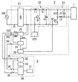
本実施形態の照明装置は、図1に示すように、光源ユニット1と、電源ユニット2と、コントローラ3とを備える。
The lighting device of the present embodiment includes a light source unit 1, a
電源ユニット2は、図1に示すように、制御回路20、整流器21、昇圧チョッパ回路22、降圧チョッパ回路23、信号変換回路24、制御電源回路25などを備えている。また、電源ユニット2は、制御信号端子261と、1対の電源供給端子262とを備え、コントローラ3と電気的に接続されている。整流器21は、ダイオードブリッジで構成され、商用の交流電源(外部電源)100から供給される交流電圧・交流電流を全波整流する。
As shown in FIG. 1, the
昇圧チョッパ回路22は、力率の改善を目的とする従来周知の力率改善回路であって、スイッチング素子Q1、インダクタL1、ダイオードD1、平滑コンデンサC1、駆動回路220などで構成されている。すなわち、インダクタL1とダイオードD1と平滑コンデンサC1の直列回路が整流器21の脈流出力端子間に電気的に接続され、ダイオードD1と平滑コンデンサC1の直列回路に対して、スイッチング素子Q1が電気的に並列接続されている。スイッチング素子Q1には、例えば、nチャネル型のパワーMOSFET(Metal-Oxide-Semiconductor Field-Effect Transistor)が使用されることが好ましい。駆動回路220は、スイッチング素子Q1のゲートに駆動信号を与えることでスイッチング素子Q1をオン・オフ(スイッチング)するように構成されている。さらに、駆動回路220は、平滑コンデンサC1の両端電圧を監視し、当該両端電圧を目標値(外部電源100の電源電圧の実効値よりも十分に高い電圧)に一致させるように、スイッチング素子Q1をPWM制御するように構成されている。ただし、このような昇圧チョッパ回路22は従来周知であるから、詳細な動作の説明は省略する。
The step-
降圧チョッパ回路23は、昇圧チョッパ回路22から入力する直流電圧・直流電流を、光源ユニット1に適した直流電圧・直流電流に降圧(電力変換)するDC/DCコンバータである。また、降圧チョッパ回路23は、スイッチング素子Q2、インダクタL2、ダイオードD2、平滑コンデンサC2などで構成されることが好ましい。すなわち、平滑コンデンサC2とインダクタL2とスイッチング素子Q2の直列回路が昇圧チョッパ回路22の出力端子間に電気的に接続され、平滑コンデンサC2とインダクタL2の直列回路に対して、ダイオードD2が電気的に並列接続されている。スイッチング素子Q2には、例えば、nチャネル型のパワーMOSFETが使用されることが好ましい。なお、スイッチング素子Q2は、制御回路20によってオン・オフ(スイッチング)される。また、平滑コンデンサC2の低電位側の端子が光源ユニット1の正極側の入力端子と電気的に接続されている。ただし、このような降圧チョッパ回路23は従来周知であるから、詳細な動作の説明は省略する。
The step-down
信号変換回路24は、後述するように、コントローラ3から制御信号端子261を介して与えられる制御信号(PWM信号)を直流の電圧信号に変換して制御回路20に出力するように構成されている。なお、信号変換回路24から出力される電圧信号の信号レベル(直流電圧レベル)は、制御信号で指示される出力レベル(調光レベル)に対応している。
The
制御電源回路25は、外部電源100の交流入力電圧から制御電圧(例えば、15ボルトの直流電圧)Vccを生成するように構成される。制御電源回路25で生成される制御電圧Vccは、制御回路20及び信号変換回路24に供給されるとともに、1対の電源供給端子262を介してコントローラ3にも供給されている。なお、1対の電源供給端子262のうちの片方は、グランド端子として使用され、コントローラ3から出力される制御信号のグランド(GND)と共有されることが好ましい。
The control
制御回路20は、スイッチング素子Q2のゲートに与える駆動信号をPWM制御することにより、インダクタL2に流れる電流を目標値に一致させるように構成されることが好ましい。また、制御回路20は、前記目標値を信号変換回路24から出力される電圧信号の信号レベル(調光レベル)に対応した値に調整することが好ましい。なお、このような制御回路20は、例えば、市販されている調光機能付きのLED照明用コントロールIC、あるいはマイクロコントローラで構成されることが好ましい。
The
コントローラ3は、制御部30と、記憶部31と、第1電源回路32と、第2電源回路33と、制御信号出力端子34と、1対の電源入力端子35とを備えることが好ましい。
The
第1電源回路32は、電源ユニット2から電源入力端子35を介して供給される制御電圧Vccを安定化するように構成されている。第2電源回路33は、第1電源回路32で安定化された制御電圧Vccから、低電圧(例えば、5ボルト)の直流電圧を生成するように構成されている。第2電源回路33で生成される直流電圧は、制御部30に供給されている。
The first
制御部30は、例えば、マイクロコントローラで構成されることが好ましい。制御部30は、第2電源回路33から供給される直流電圧で動作するよう構成されている。制御部30は、調光レベル(出力レベル)に対応するデューティー比のPWM(パルス幅変調)信号を生成し、当該PWM信号(制御信号)を制御信号出力端子34を介して電源ユニット2に送信する。
The
記憶部31は、フラッシュメモリなどの電気的に書換可能な不揮発性の半導体メモリで構成されることが好ましい。
The
本実施形態の照明装置は、電源ユニット2及びコントローラ3に各別にAC/DC変換部が設けられる場合と比較して、電力変換に伴う損失が抑制できる。
The lighting apparatus of the present embodiment can suppress the loss associated with the power conversion as compared with the case where the
本実施形態の照明装置の動作について説明する。 The operation of the lighting device of the present embodiment will be described.
外部電源100が投入されると、照明装置において、電源ユニット2の制御電源回路25が動作を開始し、制御電圧Vccを供給する。制御電圧Vccが供給され始めると、昇圧チョッパ回路22、制御回路20及びコントローラ3が動作を開始する。コントローラ3の制御部30は、PWM信号(制御信号)を生成して、電源ユニット2に送信する。電源ユニット2の制御回路20は、信号変換回路24で変換された電圧信号の信号レベルから、指示されている出力レベル(調光レベル)を判断し、スイッチング素子Q2を制御して光源ユニット1を調光点灯させる。
When the
なお、本実施形態の照明装置は、図2に示すように、複数(図示例では2つ)の電源ユニット2と、1つのコントローラ3とを備えてもよい。コントローラ3は、複数の電源ユニット2の何れか1つの電源ユニット2から制御電圧Vccが供給されるように構成されている。
The lighting device of the present embodiment may include a plurality of (two in the illustrated example)
また、本実施形態の照明装置及び電源ユニット2では、電源ユニット2に接続される光源ユニット1は1つとは限らない(図1参照)。複数の光源ユニット1は、電源ユニット2に対して、電気的に並列、又は直列に接続されていてもよい。
Further, in the lighting device and the
本実施形態の照明装置は、固体発光素子を有する1乃至複数の光源ユニット1と、外部電源100から供給される電力を電力変換して光源ユニット1に給電する電源ユニット2と、光源ユニット1に供給される電力を調整するように電源ユニット2を制御するコントローラ3とを備える。電源ユニット2は、スイッチング電源回路(降圧チョッパ回路23)と、スイッチング電源回路(降圧チョッパ回路23)の動作を制御する制御回路20と、制御回路20の動作用の電力を生成する制御電源回路25とを有する。コントローラ3は、制御部30を備え、電源ユニット2の制御電源回路25で生成される電力が供給されて動作するように構成される。制御部30は、スイッチング電源回路(降圧チョッパ回路23)の出力レベルを指示する制御信号を生成して電源ユニット2に送信する。電源ユニット2の制御回路20は、スイッチング電源回路(降圧チョッパ回路23)の動作を制御して、スイッチング電源回路(降圧チョッパ回路23)の出力電力を、前記制御信号で指示される出力レベルに対応した値に一致させるように構成される。
The lighting apparatus of the present embodiment includes one or more light source units 1 having solid light emitting elements, a
本実施形態の照明装置は上述のように構成されるので、照明装置の電力損失が抑制される。 Since the lighting device of the present embodiment is configured as described above, the power loss of the lighting device is suppressed.
本実施形態の電源ユニット2は、本実施形態の照明装置に用いられ、コントローラ3に直流電力を供給する電源供給端子262と、コントローラ3から前記制御信号を受信する制御信号端子261とを備える。
The
本実施形態の電源ユニット2は上述のように構成されるので、端子を設けることで、電源ユニット2とコントローラ3の結線が容易になる。
Since the
1 光源ユニット
100 外部電源
2 電源ユニット
20 制御回路
23 降圧チョッパ回路(スイッチング電源回路)
24 信号変換回路
25 制御電源回路
261 制御信号端子
262 電源供給端子
3 コントローラ
30 制御部
1
24
Claims (2)
前記電源ユニットは、スイッチング電源回路と、前記スイッチング電源回路の動作を制御する制御回路と、前記制御回路及び前記コントローラの動作用の電力を生成する制御電源回路とを有し、
前記コントローラは、制御部を備え、前記電源ユニットの制御電源回路で生成される電力が供給されて動作するように構成され、
前記制御部は、前記スイッチング電源回路の出力レベルを指示する制御信号を生成して前記電源ユニットに送信し、
前記電源ユニットの制御回路は、前記スイッチング電源回路の動作を制御して、前記スイッチング電源回路の出力電力を、前記制御信号で指示される出力レベルに対応した値に一致させるように構成される
ことを特徴とする照明装置。 A light source unit having solid-state light emitting elements; a power supply unit configured to convert power supplied from an external power supply to supply power to the light source unit; and the power supply to adjust power supplied to the light source unit And a controller that controls the unit,
The power supply unit includes a switching power supply circuit, a control circuit that controls the operation of the switching power supply circuit, and a control power supply circuit that generates power for the operation of the control circuit and the controller .
The controller includes a control unit and is configured to operate by being supplied with power generated by a control power supply circuit of the power supply unit.
The control unit generates a control signal indicating an output level of the switching power supply circuit and transmits the control signal to the power supply unit.
The control circuit of the power supply unit is configured to control the operation of the switching power supply circuit to match the output power of the switching power supply circuit to a value corresponding to the output level indicated by the control signal. A lighting device characterized by
ことを特徴とする電源ユニット。 A power supply unit for use in the lighting device according to claim 1, comprising: a power supply terminal for supplying DC power to the controller; and a control signal terminal for receiving the control signal from the controller.
Priority Applications (2)
| Application Number | Priority Date | Filing Date | Title |
|---|---|---|---|
| JP2015006237A JP6532002B2 (en) | 2015-01-15 | 2015-01-15 | Lighting device and power supply unit |
| DE102016100125.2A DE102016100125A1 (en) | 2015-01-15 | 2016-01-05 | Lighting assembly and power source unit |
Applications Claiming Priority (1)
| Application Number | Priority Date | Filing Date | Title |
|---|---|---|---|
| JP2015006237A JP6532002B2 (en) | 2015-01-15 | 2015-01-15 | Lighting device and power supply unit |
Publications (2)
| Publication Number | Publication Date |
|---|---|
| JP2016134210A JP2016134210A (en) | 2016-07-25 |
| JP6532002B2 true JP6532002B2 (en) | 2019-06-19 |
Family
ID=56293139
Family Applications (1)
| Application Number | Title | Priority Date | Filing Date |
|---|---|---|---|
| JP2015006237A Active JP6532002B2 (en) | 2015-01-15 | 2015-01-15 | Lighting device and power supply unit |
Country Status (2)
| Country | Link |
|---|---|
| JP (1) | JP6532002B2 (en) |
| DE (1) | DE102016100125A1 (en) |
Family Cites Families (3)
| Publication number | Priority date | Publication date | Assignee | Title |
|---|---|---|---|---|
| JP4370901B2 (en) | 2003-10-15 | 2009-11-25 | パナソニック電工株式会社 | LED lighting device |
| JP6011761B2 (en) * | 2011-12-19 | 2016-10-19 | パナソニックIpマネジメント株式会社 | Lighting device and lighting fixture using the same |
| CN104053275A (en) * | 2013-03-11 | 2014-09-17 | 硅工厂股份有限公司 | Lighting apparatus |
-
2015
- 2015-01-15 JP JP2015006237A patent/JP6532002B2/en active Active
-
2016
- 2016-01-05 DE DE102016100125.2A patent/DE102016100125A1/en not_active Withdrawn
Also Published As
| Publication number | Publication date |
|---|---|
| DE102016100125A1 (en) | 2016-07-21 |
| JP2016134210A (en) | 2016-07-25 |
Similar Documents
| Publication | Publication Date | Title |
|---|---|---|
| US8816597B2 (en) | LED driving circuit | |
| JP6143674B2 (en) | LED circuit device, LED light source and method | |
| JP5263503B2 (en) | Light emitting diode lighting device | |
| TWI468076B (en) | LED driver and LED lighting device | |
| CN105557069B (en) | There is the compact driver for integrating dual output particularly for light emitting diode | |
| JP2014160574A (en) | Led driving device and led lighting device | |
| US9699842B2 (en) | Complementary converter for switch mode power supply | |
| TWI544835B (en) | Dimming device | |
| TWI583252B (en) | Dimmer | |
| US10397998B2 (en) | Driver circuit and method | |
| US8564206B2 (en) | LED lighting device and illumination apparatus including same | |
| JP6668684B2 (en) | Lighting device and lighting equipment | |
| JP6534060B2 (en) | Lighting device and lighting apparatus | |
| JP6532002B2 (en) | Lighting device and power supply unit | |
| JP6534090B2 (en) | Lighting system | |
| JP5150742B2 (en) | LED drive circuit | |
| JP2017158292A (en) | Power supply device and lighting device | |
| JP6840997B2 (en) | Lighting equipment and lighting equipment | |
| KR20150091796A (en) | A Driving Circuit for LED lighting | |
| JP7115049B2 (en) | Lighting devices, luminaires and lighting systems | |
| JP2016189282A5 (en) | ||
| JP2017084711A (en) | Lighting device and illuminating fixture | |
| JP7310991B2 (en) | Lighting devices, luminaires and lighting systems | |
| JP7510114B2 (en) | Lighting devices and lighting fixtures | |
| JP6357790B2 (en) | Lighting device and lighting apparatus |
Legal Events
| Date | Code | Title | Description |
|---|---|---|---|
| RD02 | Notification of acceptance of power of attorney |
Free format text: JAPANESE INTERMEDIATE CODE: A7422 Effective date: 20170208 |
|
| A621 | Written request for application examination |
Free format text: JAPANESE INTERMEDIATE CODE: A621 Effective date: 20171025 |
|
| A977 | Report on retrieval |
Free format text: JAPANESE INTERMEDIATE CODE: A971007 Effective date: 20180822 |
|
| A131 | Notification of reasons for refusal |
Free format text: JAPANESE INTERMEDIATE CODE: A131 Effective date: 20180911 |
|
| A521 | Request for written amendment filed |
Free format text: JAPANESE INTERMEDIATE CODE: A523 Effective date: 20181112 |
|
| TRDD | Decision of grant or rejection written | ||
| A01 | Written decision to grant a patent or to grant a registration (utility model) |
Free format text: JAPANESE INTERMEDIATE CODE: A01 Effective date: 20190416 |
|
| A61 | First payment of annual fees (during grant procedure) |
Free format text: JAPANESE INTERMEDIATE CODE: A61 Effective date: 20190510 |
|
| R151 | Written notification of patent or utility model registration |
Ref document number: 6532002 Country of ref document: JP Free format text: JAPANESE INTERMEDIATE CODE: R151 |