JP6840997B2 - Lighting equipment and lighting equipment - Google Patents
Lighting equipment and lighting equipment Download PDFInfo
- Publication number
- JP6840997B2 JP6840997B2 JP2016214355A JP2016214355A JP6840997B2 JP 6840997 B2 JP6840997 B2 JP 6840997B2 JP 2016214355 A JP2016214355 A JP 2016214355A JP 2016214355 A JP2016214355 A JP 2016214355A JP 6840997 B2 JP6840997 B2 JP 6840997B2
- Authority
- JP
- Japan
- Prior art keywords
- lighting device
- terminal
- output
- lighting
- light source
- Prior art date
- Legal status (The legal status is an assumption and is not a legal conclusion. Google has not performed a legal analysis and makes no representation as to the accuracy of the status listed.)
- Active
Links
- 239000003990 capacitor Substances 0.000 description 31
- 238000001514 detection method Methods 0.000 description 25
- 238000010586 diagram Methods 0.000 description 4
- 238000005265 energy consumption Methods 0.000 description 4
- 238000009413 insulation Methods 0.000 description 2
- 238000004519 manufacturing process Methods 0.000 description 2
- 238000000034 method Methods 0.000 description 2
- 230000004048 modification Effects 0.000 description 2
- 238000012986 modification Methods 0.000 description 2
- 238000006243 chemical reaction Methods 0.000 description 1
- 230000007423 decrease Effects 0.000 description 1
- 230000010355 oscillation Effects 0.000 description 1
- 239000004065 semiconductor Substances 0.000 description 1
- 238000004904 shortening Methods 0.000 description 1
- 230000000087 stabilizing effect Effects 0.000 description 1
- 238000003860 storage Methods 0.000 description 1
Images

Description
本発明は、照明装置および照明器具に関する。 The present invention relates to luminaires and luminaires.
光源のLED化および直流給電の実用化に伴い、直流給電を考慮した点灯装置が見出されている。特許文献1および特許文献2には、直流給電の点灯装置が開示されている。
With the use of LEDs as light sources and the practical application of DC power supply, lighting devices that take DC power supply into consideration have been found.
一般に、点灯装置は、照明装置が使用される用途に応じて光源部に供給する電流および電圧を変えることで、光源部の明るさを変えている。また、点灯装置の回路方式には様々な種類が見出されている。一方で、省資源化を目的とした生産設備の標準化および部品の標準化によって、光源部に供給するべき電流および電圧に対して、最適な回路方式および部品仕様を備えた点灯装置を提供できない場合がある。このため、照明装置の消費エネルギーの低減および部品の小型化が妨げられる場合がある。 In general, the lighting device changes the brightness of the light source unit by changing the current and voltage supplied to the light source unit according to the application in which the lighting device is used. In addition, various types of circuit systems for lighting devices have been found. On the other hand, due to the standardization of production equipment and parts for the purpose of resource saving, it may not be possible to provide a lighting device having the optimum circuit method and parts specifications for the current and voltage to be supplied to the light source unit. is there. Therefore, reduction of energy consumption of the lighting device and miniaturization of parts may be hindered.
本発明は、上述の課題を解決するためになされたもので、消費電力の低減が可能な照明装置および照明器具を得ることを目的とする。 The present invention has been made to solve the above-mentioned problems, and an object of the present invention is to obtain a luminaire and a luminaire capable of reducing power consumption.
本発明に係る照明装置は、直流電源に接続され、第1スイッチング素子のオンオフによって光源に供給する電圧を発生させる第1点灯装置と、該直流電源に接続され、第2スイッチング素子のオンオフによって該光源に供給する電圧を発生させる第2点灯装置と、を備え、該第2点灯装置の出力は、該第1点灯装置の出力に接続されていることを特徴とする照明装置であって該第1点灯装置は、該第1点灯装置の出力の高電位側の端子であり、該光源に供給する電圧を出力する第1出力端子と、該第1点灯装置の出力の低電位側の端子である第2出力端子と、該第1点灯装置の出力の高電位側の端子であり、該第1出力端子に接続された第1補助端子と、該第1点灯装置の出力の低電位側の端子であり、該第2出力端子に接続された第2補助端子と、を備え、該第2点灯装置は、該第2点灯装置の出力の高電位側の端子であり、該光源に供給する電圧を出力する第3出力端子と、該第2点灯装置の出力の低電位側の端子である第4出力端子と、を備え、該第1出力端子および該第2出力端子は該光源に接続され、該第1補助端子は、該第3出力端子に接続され、該第2補助端子は、該第4出力端子に接続されることを特徴とする。
The lighting device according to the present invention is connected to a DC power supply and is connected to a first lighting device that generates a voltage to be supplied to a light source by turning on / off the first switching element, and is connected to the DC power supply and is connected to the DC power supply by turning on / off the second switching element. A lighting device comprising a second lighting device that generates a voltage to be supplied to a light source, and the output of the second lighting device is connected to the output of the first lighting device . The 1 lighting device is a terminal on the high potential side of the output of the first lighting device, a first output terminal that outputs a voltage supplied to the light source, and a terminal on the low potential side of the output of the first lighting device. A second output terminal, a terminal on the high potential side of the output of the first lighting device, a first auxiliary terminal connected to the first output terminal, and a terminal on the low potential side of the output of the first lighting device. It is a terminal and includes a second auxiliary terminal connected to the second output terminal, and the second lighting device is a terminal on the high potential side of the output of the second lighting device and supplies the light source. A third output terminal for outputting a voltage and a fourth output terminal which is a terminal on the low potential side of the output of the second lighting device are provided, and the first output terminal and the second output terminal are connected to the light source. The first auxiliary terminal is connected to the third output terminal, and the second auxiliary terminal is connected to the fourth output terminal .
本発明に係る照明装置は、光源に対して第1点灯装置および第2点灯装置から電流を供給する。このため、1つの点灯装置から電流を供給するよりも、第1スイッチング素子および第2スイッチング素子による導通損失を低減できる。従って、照明装置の消費電力を低減できる。 The lighting device according to the present invention supplies a current to the light source from the first lighting device and the second lighting device. Therefore, the conduction loss due to the first switching element and the second switching element can be reduced as compared with the case where the current is supplied from one lighting device. Therefore, the power consumption of the lighting device can be reduced.
本発明の実施の形態に係る照明装置および照明器具について図面を参照して説明する。同じ又は対応する構成要素には同じ符号を付し、説明の繰り返しを省略する場合がある。 The luminaire and the luminaire according to the embodiment of the present invention will be described with reference to the drawings. The same or corresponding components may be designated by the same reference numerals and the description may be omitted.
実施の形態1.
図1は、実施の形態1に係る照明器具の回路ブロック図である。本実施の形態に係る照明器具100は、照明装置101と、光源部50を備える。光源部50は複数の光源51を備える。複数の光源51は直列に接続される。光源51はLEDである。光源部50が備える光源51の数は、1個以上であれば良い。また、複数の光源51は、並列または直並列に接続されても良い。
FIG. 1 is a circuit block diagram of a lighting fixture according to the first embodiment. The
照明装置101は、第1点灯装置10および第2点灯装置20を備える。第1点灯装置10は入力である接続部CN1を備える。接続部CN1は直流電源DCに接続される。第1点灯装置10は出力である接続部CN2を備える。接続部CN2は、接続部CN5に接続される。第2点灯装置20は入力である接続部CN3を備える。接続部CN3は直流電源DCに接続される。第2点灯装置20は出力である接続部CN4を備える。接続部CN4は、接続部CN5に接続される。また、第2点灯装置20の出力は、第1点灯装置10の出力に接続されている。直流電源DCは、例えば蓄電池または太陽電池などの直流電源、または、商用電源から変換して得られる定電圧の直流電源を含むものとする。
The
光源51は、接続部CN5を介して第1点灯装置10および第2点灯装置20と接続される。第1点灯装置10と第2点灯装置20は並列に接続される。光源51には、第1点灯装置10の出力電流と、第2点灯装置20の出力電流と、を足し合わせた電流が流れる。
The
第1点灯装置10は、コンデンサC1を備える。コンデンサC1の正極は、直流電源DCの正極に接続される。コンデンサC1の負極は、直流電源DCの負極に接続される。コンデンサC1は、直流電源DCから入力される電流を整流する。また、コンデンサC1は、後述するバックコンバータ回路部が動作するための電荷を蓄える。
The
第1点灯装置10は、コンデンサC1と並列に接続された点灯回路40を備える。コンデンサC1の両端に発生する電圧は、点灯回路40の電源となる。点灯回路40の出力は、接続部CN2と接続される。点灯回路40の出力電圧は光源51に供給される。
The
点灯回路40は、第1スイッチング素子Q1を有する。第1スイッチング素子Q1は、MOSFET(Metal−Oxide−Semiconductor Field−Effect Transistor)である。第1スイッチング素子Q1のドレインは、コンデンサC1の正極に接続される。第1スイッチング素子Q1のソースには、ダイオードD1のカソードと、インダクタL1の一端が接続される。
The
第1スイッチング素子Q1のゲートには、第1点灯制御部30のゲートドライブ端子31が接続される。ダイオードD1のアノードは、コンデンサC1の負極と接続される。インダクタL1の他端は、コンデンサC2の正極および接続部CN2の高電位側に接続される。コンデンサC2の負極は接続部CN2の低電位側に接続される。
The
コンデンサC2の正極には、抵抗R2の一端が接続される。抵抗R2の他端は、抵抗R3の一端および第1点灯制御部30の電圧検出端子32に接続される。抵抗R3の他端はグランドに接続される。また、第1点灯装置10は検出抵抗R1を備える。検出抵抗R1の一端はコンデンサC1の負極と接続される。検出抵抗R1の他端は、第1点灯制御部30のLED電流検出端子33および接続部CN2の低電位側に接続される。第1点灯制御部30のグランド端子は、直流電源DCの負極に接続される。直流電源DCの負極はグランドに接続される。
One end of the resistor R2 is connected to the positive electrode of the capacitor C2. The other end of the resistor R2 is connected to one end of the resistor R3 and the
点灯回路40は、第1スイッチング素子Q1のオンオフによって光源51に供給する電圧を発生させる。インダクタL1、第1スイッチング素子Q1およびダイオードD1はバックコンバータ回路部を構成する。バックコンバータ回路部の出力には、コンデンサC2が接続される。コンデンサC2は、バックコンバータ回路部の出力電圧であるスイッチング電圧を整流する。コンデンサC2により、バックコンバータ回路部の出力電圧を安定させている。コンデンサC2に印加される電圧は、第1点灯装置10の出力電圧となる。第1点灯装置10の出力電圧は光源部50に供給される。
The
バックコンバータ回路部の動作を説明する。インダクタL1は、第1スイッチング素子Q1と接続部CN2の高電位側との間に接続される。第1スイッチング素子Q1がオンすると、インダクタL1にエネルギーが蓄えられる。第1スイッチング素子Q1がオフすると、ダイオードD1を通り、インダクタL1に蓄えられたエネルギーが還流する。コンデンサC2は、インダクタL1が出力するスイッチング電圧を整流する。第1スイッチング素子Q1のゲートは、第1点灯制御部30のゲートドライブ端子31に接続される。第1点灯制御部30は、ゲートドライブ端子31を介して第1スイッチング素子Q1を駆動する。第1点灯制御部30は、第1スイッチング素子Q1のオンオフを制御する。
The operation of the back converter circuit section will be described. The inductor L1 is connected between the first switching element Q1 and the high potential side of the connecting portion CN2. When the first switching element Q1 is turned on, energy is stored in the inductor L1. When the first switching element Q1 is turned off, the energy stored in the inductor L1 is refluxed through the diode D1. The capacitor C2 rectifies the switching voltage output by the inductor L1. The gate of the first switching element Q1 is connected to the
また、検出抵抗R1には、光源部50を流れる電流が流れる。第1点灯制御部30は、検出抵抗R1に流れる電流を、LED電流検出端子33を用いて検出する。検出された電流は、電圧に変換される。以上から、第1点灯制御部30は、検出抵抗R1に印加される電圧を検出する。第1点灯制御部30は、検出抵抗R1に印加される電圧が予め定めた目標電圧と一致するように、第1スイッチング素子Q1をスイッチングする。
Further, a current flowing through the
第1点灯制御部30は、第1スイッチング素子Q1のオン時間、オフ時間、動作周波数またはオンDUTYを調整する。第1点灯制御部30は、点灯回路40から出力される平均電流が一定になるように第1スイッチング素子Q1をオンオフしている。これにより、接続部CN2に光源部50を接続した場合は、光源部50を流れる電流が一定になるように定電流制御できる。
The first
また、抵抗R2と抵抗R3の直列回路が、コンデンサC2の正極とグランドとの間に接続される。コンデンサC2の正極とグランドの間に印加される電圧は、抵抗R2および抵抗R3によって分圧される。分圧された電圧は、電圧検出端子32に入力される。第1点灯制御部30は、電圧検出端子32から点灯回路40の出力電圧を検出する。これにより、出力過電圧を検出できる。
Further, a series circuit of the resistor R2 and the resistor R3 is connected between the positive electrode of the capacitor C2 and the ground. The voltage applied between the positive electrode and the ground of the capacitor C2 is divided by the resistors R2 and R3. The divided voltage is input to the
本実施の形態に係る第1点灯装置10は、出力過電圧を検出することで点灯回路40の出力電圧が上がり過ぎないよう保護を行う。電圧検出端子32に印加される電圧が一定値よりも高くなると、第1点灯制御部30は、第1スイッチング素子Q1の発振を停止させる。この結果、点灯回路40の出力電圧が低下する。
The
接続部CN2に光源部50が未接続の状態で、第1点灯装置10が点灯動作をすると、接続部CN2の出力電圧は、光源部50が接続されている場合に比べて高くなる。これは、点灯回路40が定電流制御で動作しているためである。光源部50が未接続の状態では、検出抵抗R1に電流が流れない。検出抵抗R1に発生する電圧が低いと、第1点灯制御部30は点灯回路40の供給電力を上げるために、第1スイッチング素子Q1のオン時間を長くする。この結果、点灯回路40の出力電圧が上昇する。
When the
点灯回路40の出力電圧が高くなると、第1点灯装置10を構成する各部品の耐圧を高める必要がある。このため、第1点灯装置10が大型になる。上述した出力過電圧に対する保護動作が行われない場合、点灯回路40の出力電圧の最大値は、直流電源DCの電圧である。本実施の形態では、第1点灯制御部30は、グランドとコンデンサC2の正極との間の電圧が閾値よりも大きくなると第1スイッチング素子Q1をオフする。この結果、点灯回路40の出力電圧は、閾値以下になるように制御される。従って、第1点灯装置10の大型化を抑制できる。
When the output voltage of the
第2点灯装置20の構成は、第1点灯装置10と同様である。第2点灯装置20は、直流電源DCと並列に接続されたコンデンサC3を備える。第2点灯装置20は、コンデンサC3と並列に接続された点灯回路70を備える。点灯回路70の出力は、接続部CN4と接続される。点灯回路70の出力電圧は光源51に供給される。
The configuration of the
点灯回路70は、第2スイッチング素子Q2を有する。第2スイッチング素子Q2のドレインは、コンデンサC3の正極に接続される。第2スイッチング素子Q2のソースには、ダイオードD2のカソードと、インダクタL2の一端が接続される。第2スイッチング素子Q2のゲートには、第2点灯制御部60のゲートドライブ端子61が接続される。ダイオードD2のアノードは、コンデンサC3の負極と接続される。インダクタL2の他端は、コンデンサC4の正極および接続部CN4の高電位側に接続される。コンデンサC4の負極は接続部CN4の低電位側に接続される。
The
コンデンサC4の正極には、抵抗R5の一端が接続される。抵抗R5の他端は、抵抗R6の一端および第2点灯制御部60の電圧検出端子62に接続される。抵抗R6の他端はグランドに接続される。また、第2点灯装置20は検出抵抗R4を備える。検出抵抗R4の一端はコンデンサC3の負極と接続される。検出抵抗R4の他端は、第2点灯制御部60のLED電流検出端子63および接続部CN4の低電位側に接続される。第2点灯制御部60のグランド端子は、直流電源DCの負極に接続される。
One end of the resistor R5 is connected to the positive electrode of the capacitor C4. The other end of the resistor R5 is connected to one end of the resistor R6 and the
点灯回路70は、第2スイッチング素子Q2のオンオフによって光源51に供給する電圧を発生させる。インダクタL2、第2スイッチング素子Q2およびダイオードD2はバックコンバータ回路部を構成する。バックコンバータ回路部の動作は、第1点灯装置10と同様である。バックコンバータ回路部の出力には、スイッチング電圧を整流するコンデンサC4が接続される。第2点灯制御部60は、ゲートドライブ端子61を介して第2スイッチング素子Q2を駆動する。
The
第1点灯制御部30と同様に、第2点灯制御部60は、検出抵抗R4に流れる電流を、LED電流検出端子63を用いて検出する。第2点灯制御部60は、検出抵抗R4に印加される電圧が予め定めた目標電圧と一致するように、第2スイッチング素子Q2をスイッチングする。つまり、第2点灯制御部60は、点灯回路70から出力される平均電流が一定になるように第2スイッチング素子Q2をオンオフしている。従って、光源部50を流れる電流が一定になるように定電流制御できる。
Similar to the first
また、抵抗R5と抵抗R6の直列回路によって分圧された電圧は、電圧検出端子62に入力される。第2点灯制御部60は、電圧検出端子62から点灯回路70の出力電圧を検出する。従って、第1点灯制御部30と同様に、第2点灯制御部60は、出力過電圧を検出できる。このため、点灯回路40と同様に、点灯回路70の出力電圧は閾値以下になるように制御される。
Further, the voltage divided by the series circuit of the resistor R5 and the resistor R6 is input to the
本実施の形態では、第1点灯装置10と第2点灯装置20は共通の直流電源DCに接続される。また、第1点灯装置10と第2点灯装置20は共通の光源部50に接続される。これにより、光源部50において、第1点灯装置10から供給される電力および第2点灯装置20から供給される電力によって光源51が点灯する。
In the present embodiment, the
第1点灯装置10および第2点灯装置20を光源部50に接続した状態においても、点灯回路40および点灯回路70から出力される平均電流は点灯装置毎に制御できる。第1点灯装置10と、第2点灯装置20の出力電流は、それぞれ独立して一定に制御される。従って、光源51の明るさは、第1点灯装置10からの出力電流と第2点灯装置20からの出力電流の合成電流で決定される。本実施の形態に係る照明器具100では、複数の定電流型の点灯装置を使用して光源部50に流れる電流値の調整を実現する。
Even when the
一般に、光源51を明るく点灯させるためには光源51を流れる電流を増やす。光源51を流れる電流を増やすには、直流電源DCの電圧、点灯装置の出力電圧または出力電流を増やすことが考えられる。ここで、点灯装置として第1点灯装置10のみを備える照明器具を考える。このとき、直流電源DCの電圧、点灯装置の出力電圧または出力電流を増やすと、インダクタL1およびコンデンサC2が大型化する可能性がある。このように、点灯装置を1つのみ備える照明器具では、光源51の明るさの変更に伴い、点灯装置の構成部品が大型化する場合がある。従って、点灯装置に使用する部品の標準化が妨げられる可能性がある。
Generally, in order to light the
これに対し、本実施の形態に係る照明器具100では、第1点灯装置10と第2点灯装置20から光源部50に電流が供給される。本実施の形態では、光源部50に接続される点灯装置の数を増やすことで、光源51に流れる電流を増やすことができる。つまり、光源51を明るくするために、第1点灯装置10および第2点灯装置20のそれぞれの出力電流を大きくする必要がない。このため、第1点灯装置10および第2点灯装置20の構成部品を大型にする必要がない。従って、部品の小型化が可能になる。
On the other hand, in the
また、本実施の形態では、光源51の明るさの変更に伴い、第1点灯装置10および第2点灯装置20の構成部品を変更する必要がない。従って、部品および生産設備を標準化できる。本実施の形態では、照明器具100の明るさの変更を考慮して、複数の種類の部品を準備する必要が無い。このため、照明器具100を少ない資源から製造できる。
Further, in the present embodiment, it is not necessary to change the components of the
また、一般に、点灯装置の構成部品が標準化されると、光源部50に供給するべき電流および電圧に適した部品仕様または出力仕様の点灯装置を提供できない場合が考えられる。これに対し、本実施の形態では、光源部50に接続される点灯装置の数を変更することで、光源部50に供給する電流および電圧を調節できる。従って、第1点灯装置10および第2点灯装置20の構成部品を標準化しても、光源部50に適した電流および電圧を供給できる。
Further, in general, when the components of the lighting device are standardized, it may not be possible to provide a lighting device having component specifications or output specifications suitable for the current and voltage to be supplied to the
本実施の形態に係る照明器具100は、光源部50に接続する点灯装置の数を変更することで、様々な明るさを提供する。このため、目標とする光源51の明るさに係らず、第1点灯装置10および第2点灯装置20の各々について、構成部品または回路方式に適した出力電流を設定できる。つまり、本実施の形態では、第1点灯装置10および第2点灯装置20を適した動作条件で動作させることができる。従って、第1点灯装置10および第2点灯装置20における電力の損失を低減できる。従って、照明器具100の消費エネルギーを低減できる。
The
また、第1点灯装置10の出力電流Iを2倍にすることを考える。直流電源DCの正極と接続部CN2の高電位側との間の電位差を一定に保ち、接続部CN2からの出力電流Iを2倍にすると、第1スイッチング素子Q1を流れる平均電流は2倍になる。これに伴い、第1スイッチング素子Q1を流れる実効電流も2倍になる。ここで、第1スイッチング素子Q1の導通損失は実効電流の二乗に比例する。このため、導通損失は4倍になる。導通損失はオンロスとも言う。
Also, consider doubling the output current I of the
これに対し、第1点灯装置10と第2点灯装置20の各々から出力電流Iを供給する場合を考える。この場合も、光源部50に供給される電流は、第1点灯装置10の出力電流Iの2倍となる。この時、照明器具100の導通損失は、第1点灯装置10と第2点灯装置20が同じ回路であると仮定すると、第1点灯装置10の導通損失の2倍になる。従って、第1点灯装置10の出力電流を2倍にするよりも、第1点灯装置10と第2点灯装置20のそれぞれから出力電流を供給したほうが、導通損失が小さい。このため、照明器具100は、点灯装置を1つのみ備える照明器具よりも消費電力を低減できる。
On the other hand, consider a case where the output current I is supplied from each of the
また、一般に、商用電源から電源供給を受ける複数の点灯装置から共通の光源を点灯させる照明器具では、動作が不安定になる可能性がある。これは、AC−DC変換時に点灯装置毎に回路の位相が異なるためである。本実施の形態では、直流給電を使用することで上記の懸念はなくなり、安定した動作を実現できる。 Further, in general, a lighting fixture that lights a common light source from a plurality of lighting devices supplied with power from a commercial power source may become unstable in operation. This is because the phase of the circuit is different for each lighting device during AC-DC conversion. In the present embodiment, the above concern is eliminated by using the DC power supply, and stable operation can be realized.
また、点灯装置毎にグランドが異なると、照明器具の動作が不安定になる可能性がある。これに対し、本実施の形態では、第1点灯制御部30、第2点灯制御部60、点灯回路40および点灯回路70は、直流電源DCの負極をグランドとして動作する。第1点灯制御部30、第2点灯制御部60、点灯回路40および点灯回路70のグランドは同電位である。つまり、第1点灯装置10と第2点灯装置20は同一の制御グランドを基準に動作する。従って、第1点灯装置10と第2点灯装置20が光源部50を介して接続されていても、照明器具100の安定した動作が可能になる。
Further, if the ground is different for each lighting device, the operation of the luminaire may become unstable. On the other hand, in the present embodiment, the first
また、商用電源から電源供給を受ける複数の点灯装置から共通の光源を点灯させる照明器具において、動作を安定させる方法として、フライバック回路などの絶縁型回路を使用することが考えられる。このとき、各々の点灯装置において、点灯制御部の制御グランドが交流電源から分離される。このとき、複数の点灯装置から光源を共通に点灯させる場合にも、照明器具を安定して動作させることができる。しかし、一般に絶縁型回路は、バックコンバータ回路などの非絶縁型の点灯回路に比べて回路損失が大きい。このため、消費エネルギーが大きくなる場合がある。 Further, in a lighting fixture that lights a common light source from a plurality of lighting devices that receive power from a commercial power source, it is conceivable to use an insulated circuit such as a flyback circuit as a method for stabilizing the operation. At this time, in each lighting device, the control ground of the lighting control unit is separated from the AC power supply. At this time, even when the light sources are commonly lit from a plurality of lighting devices, the luminaire can be operated stably. However, in general, an isolated circuit has a larger circuit loss than a non-insulated lighting circuit such as a back converter circuit. Therefore, energy consumption may increase.
これに対し、本実施の形態では、直流電源DCから給電を行う。第1点灯装置10と第2点灯装置20の制御グランドは、直流電源DCの負極である。このため、第1点灯装置10および第2点灯装置20が備えるスイッチング電源回路が非絶縁型の回路であっても、動作を安定させることができる。従って、消費エネルギーを低減できる。
On the other hand, in the present embodiment, power is supplied from the DC power supply DC. The control ground of the
本実施の形態に係る第1点灯装置10と第2点灯装置20は、それぞれ非絶縁型のスイッチング電源回路が設けられている。本実施の形態において、非絶縁型のスイッチング電源回路はバックコンバータ回路部である。この変形例として、第1点灯装置10と第2点灯装置20が備えるスイッチング電源回路は、昇圧チョッパ回路またはSEPIC(Single Ended Primary Inductor Converter)回路などの非絶縁制御方式の回路であっても良い。また、第1点灯装置10と第2点灯装置20が備えるスイッチング電源回路は、フライバック回路などの絶縁制御方式の回路であっても良い。
The
また、第1点灯装置10が備えるスイッチング電源回路と、第2点灯装置20が備えるスイッチング電源回路は、異なる回路であっても良い。また、第1点灯装置10と第2点灯装置20の出力電流は異なっていても問題ない。さらに、第1点灯装置10と第2点灯装置20は、それぞれ外部のコントローラなどから調光制御されるものとしても良い。また、本実施の形態に係る照明器具100は、第1点灯装置10と第2点灯装置20を備えるが、照明器具100が備える点灯装置は3つ以上でも良い。
Further, the switching power supply circuit included in the
これらの変形は以下の実施の形態に係る照明装置および照明器具について適宜応用することができる。なお、以下の実施の形態に係る照明装置および照明器具については実施の形態1との共通点が多いので、実施の形態1との相違点を中心に説明する。 These modifications can be appropriately applied to the luminaire and the luminaire according to the following embodiments. Since the lighting devices and lighting fixtures according to the following embodiments have much in common with the first embodiment, the differences from the first embodiment will be mainly described.
実施の形態2.
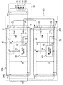
図2は、実施の形態2に係る照明器具の回路ブロック図である。実施の形態2に係る照明器具200は、照明装置201と、光源部50を備える。本実施の形態に係る照明装置201は、照明装置101と比べて、接続部CN2および接続部CN4の構成が異なっている。接続部CN2は、第1出力部を備える。第1出力部は、第1出力端子11と、第2出力端子14を備える。第1出力端子11は接続部CN2の高電位側の端子であり、光源51に供給する電圧を出力する。第2出力端子14は、接続部CN2の低電位側の端子である。第2出力端子14は、接地用の端子であり、グランドと接続される。
FIG. 2 is a circuit block diagram of the lighting fixture according to the second embodiment. The
また、接続部CN2は、第1出力部に接続された第1補助部を備える。第1補助部は、第1出力端子11に接続された第1補助端子12を備える。さらに、第1補助部は、第2出力端子14に接続された第2補助端子13を備える。本実施の形態に係る第1点灯装置210において、接続部CN2は高電位側に+1および+2の2つの端子を備える。また、接続部CN2は、低電位側に−1及び−2の2つの端子を備える。接続部CN2は、2極の端子を2つ備えている。
Further, the connection unit CN2 includes a first auxiliary unit connected to the first output unit. The first auxiliary unit includes a first
また、接続部CN4は、第2出力部を備える。第2出力部は、第3出力端子21と、第4出力端子24を備える。第3出力端子21は接続部CN4の高電位側の端子であり、光源51に供給する電圧を出力する。第4出力端子24は、接続部CN4の低電位側の端子である。第4出力端子24は、接地用の端子であり、グランドと接続される。
Further, the connection unit CN4 includes a second output unit. The second output unit includes a
また、接続部CN4は、第2出力部に接続された第2補助部を備える。第2補助部は、第3出力端子21に接続された第3補助端子22を備える。さらに、第2補助部は、第4出力端子24に接続された第4補助端子23を備える。本実施の形態に係る第2点灯装置220において、第1点灯装置210と同様に、接続部CN4は高電位側に+1および+2の2つの端子を備える。また、接続部CN4は、低電位側に−1及び−2の2つの端子を備える。このように、接続部CN2は2極の端子を2つ備えている。
Further, the connection unit CN4 includes a second auxiliary unit connected to the second output unit. The second auxiliary unit includes a third
第1出力端子11と、第2出力端子14は光源51に接続される。第1補助部は、第2出力部に接続される。第1補助端子12は、第3出力端子21に接続される。第2補助端子13は、第4出力端子24に接続される。これにより、実施の形態1と同様に、第1点灯装置210と第2点灯装置220は、光源部50に接続される。光源部50には、第1点灯装置210の出力電流と第2点灯装置220の出力電流を足し合わせた電流が流れる。
The
実施の形態1において、光源部50に第1点灯装置10が接続された状態で、さらに第2点灯装置20を光源部50に接続するためには、追加の配線が必要となる。これに対し、本実施の形態に係る照明器具200では、第1点灯装置210は第1補助端子12および第2補助端子13を備える。また、第2点灯装置220は第3補助端子22および第4補助端子23を備える。これにより、接続部CN4を接続部CN2に接続することで、実施の形態1と同様の回路を構成できる。従って、光源部50に第1点灯装置210が接続された状態で、さらに第2点灯装置220を光源部50に接続する場合に、追加の配線が必要ない。
In the first embodiment, in the state where the
使用者が照明器具100を使用する際、光源部50の明るさを暗くする場合は、点灯回路40および点灯回路70を用いて調光制御すれば良い。調光制御において、第1スイッチング素子Q1および第2スイッチング素子Q2のオン時間を短くすることで光源部50の明るさを暗くできる。これに対し、光源部50の明るさの最大値を大きくするには、第1点灯装置10、第2点灯装置20、光源部50または照明器具100を交換する必要がある。
When the user uses the
これに対し、本実施の形態では、照明器具200に配線を追加しなくても、第2点灯装置220を光源部50に接続できる。このため、配線を追加せずに光源部50への供給電力を増やすことができる。光源部50に第1点灯装置210が接続された状態において、使用者が光源部50の明るさの最大値を大きくしたい場合には、照明器具200に第2点灯装置220を接続する。ここで、第3出力端子21と第4出力端子24を、第1補助端子12と第2補助端子13にそれぞれ接続する。これにより、照明器具200に第2点灯装置220が取り付けられる。
On the other hand, in the present embodiment, the
従って、光源部50の明るさの最大値を容易に大きくできる。また、光源部50の明るさの最大値を大きくするために、点灯装置、光源部50または照明器具200の交換をする必要がない。従って、廃却される部材を低減できる。また、各々の点灯装置が出力端子および補助端子を備えることで、第1点灯装置210および第2点灯装置220の構造を標準化できる。
Therefore, the maximum value of the brightness of the
また、本実施の形態に係る照明器具200は2つの点灯装置を備える。これに対し、さらに光源部50を明るくしたい場合は、照明器具200は3つ以上の点灯装置を備えても良い。この場合、第2点灯装置220の第3補助端子22および第4補助端子23に、別の点灯装置の出力端子を接続する。なお、各実施の形態で説明した技術的特徴は適宜に組み合わせて用いてもよい。
Further, the
100、200 照明器具、101、201 照明装置、DC 直流電源、Q1 第1スイッチング素子、Q2 第2スイッチング素子、10、210 第1点灯装置、20、220 第2点灯装置、51 光源、11 第1出力端子、14 第2出力端子、12 第1補助端子、13 第2補助端子、21 第3出力端子、24 第4出力端子、22 第3補助端子、23 第4補助端子、30 第1点灯制御部、60 第2点灯制御部 100, 200 Lighting equipment, 101, 201 Lighting equipment, DC DC power supply, Q1 1st switching element, Q2 2nd switching element, 10, 210 1st lighting equipment, 20, 220 2nd lighting equipment, 51 Light source, 11 1st Output terminal, 14 2nd output terminal, 12 1st auxiliary terminal, 13 2nd auxiliary terminal, 21 3rd output terminal, 24 4th output terminal, 22 3rd auxiliary terminal, 23 4th auxiliary terminal, 30 1st lighting control Unit, 60 Second lighting control unit
Claims (4)
前記直流電源に接続され、第2スイッチング素子のオンオフによって前記光源に供給する電圧を発生させる第2点灯装置と、
を備え、
前記第2点灯装置の出力は、前記第1点灯装置の出力に接続されていることを特徴とする照明装置であって、
前記第1点灯装置は、
前記第1点灯装置の出力の高電位側の端子であり、前記光源に供給する電圧を出力する第1出力端子と、
前記第1点灯装置の出力の低電位側の端子である第2出力端子と、
前記第1点灯装置の出力の高電位側の端子であり、前記第1出力端子に接続された第1補助端子と、
前記第1点灯装置の出力の低電位側の端子であり、前記第2出力端子に接続された第2補助端子と、
を備え、
前記第2点灯装置は、
前記第2点灯装置の出力の高電位側の端子であり、前記光源に供給する電圧を出力する第3出力端子と、
前記第2点灯装置の出力の低電位側の端子である第4出力端子と、
を備え、
前記第1出力端子および前記第2出力端子は前記光源に接続され、
前記第1補助端子は、前記第3出力端子に接続され、
前記第2補助端子は、前記第4出力端子に接続されることを特徴とする照明装置。 A first lighting device that is connected to a DC power supply and generates a voltage to be supplied to the light source by turning the first switching element on and off.
A second lighting device that is connected to the DC power supply and generates a voltage to be supplied to the light source by turning on and off the second switching element.
With
The output of the second lighting device is a lighting device characterized in that it is connected to the output of the first lighting device .
The first lighting device is
A terminal on the high potential side of the output of the first lighting device, a first output terminal that outputs a voltage supplied to the light source, and a terminal.
The second output terminal, which is the terminal on the low potential side of the output of the first lighting device,
A terminal on the high potential side of the output of the first lighting device, a first auxiliary terminal connected to the first output terminal, and
A second auxiliary terminal which is a terminal on the low potential side of the output of the first lighting device and is connected to the second output terminal,
With
The second lighting device is
A third output terminal that is a terminal on the high potential side of the output of the second lighting device and outputs a voltage supplied to the light source, and a third output terminal.
The fourth output terminal, which is the terminal on the low potential side of the output of the second lighting device, and
With
The first output terminal and the second output terminal are connected to the light source, and the first output terminal and the second output terminal are connected to the light source.
The first auxiliary terminal is connected to the third output terminal.
The lighting device is characterized in that the second auxiliary terminal is connected to the fourth output terminal .
前記第2点灯装置の出力の高電位側の端子であり、前記第3出力端子に接続された第3補助端子と、
前記第2点灯装置の出力の低電位側の端子であり、前記第4出力端子に接続された第4補助端子と、
を備え、
前記第3出力端子および前記第4出力端子は前記光源に直接接続されずに、前記光源に接続された前記第1点灯装置の前記第1補助端子及び前記第2補助端子に接続されることで前記光源に電流を供給し、
前記第3補助端子および前記第4補助端子は、前記第1点灯装置および前記第2点灯装置とは別の点灯装置の出力端子が接続されることを特徴とする請求項1に記載の照明装置。 The second lighting device is
A terminal on the high potential side of the output of the second lighting device, and a third auxiliary terminal connected to the third output terminal.
The terminal on the low potential side of the output of the second lighting device, the fourth auxiliary terminal connected to the fourth output terminal, and
With
The third output terminal and the fourth output terminal are not directly connected to the light source, but are connected to the first auxiliary terminal and the second auxiliary terminal of the first lighting device connected to the light source. A current is supplied to the light source to
The lighting device according to claim 1, wherein the third auxiliary terminal and the fourth auxiliary terminal are connected to an output terminal of a lighting device different from the first lighting device and the second lighting device. ..
前記第2スイッチング素子のオンオフを制御する第2点灯制御部と、
前記第1点灯装置と、前記第2点灯装置にそれぞれ設けられた非絶縁型のスイッチング電源回路と、
を備え、
前記第1点灯制御部のグランドと、前記第2点灯制御部のグランドは同電位であることを特徴とする請求項1または2に記載の照明装置。 A first lighting control unit that controls the on / off of the first switching element, and
A second lighting control unit that controls the on / off of the second switching element, and
A non-isolated switching power supply circuit provided in the first lighting device and the second lighting device, respectively.
With
The lighting device according to claim 1 or 2, wherein the ground of the first lighting control unit and the ground of the second lighting control unit have the same potential.
前記第1点灯装置と前記第2点灯装置と接続された前記光源と、
を備えることを特徴とする照明器具。 The lighting device according to any one of claims 1 to 3,
The first lighting device, the light source connected to the second lighting device, and the light source.
Lighting equipment characterized by being equipped with.
Priority Applications (1)
| Application Number | Priority Date | Filing Date | Title |
|---|---|---|---|
| JP2016214355A JP6840997B2 (en) | 2016-11-01 | 2016-11-01 | Lighting equipment and lighting equipment |
Applications Claiming Priority (1)
| Application Number | Priority Date | Filing Date | Title |
|---|---|---|---|
| JP2016214355A JP6840997B2 (en) | 2016-11-01 | 2016-11-01 | Lighting equipment and lighting equipment |
Publications (2)
| Publication Number | Publication Date |
|---|---|
| JP2018073702A JP2018073702A (en) | 2018-05-10 |
| JP6840997B2 true JP6840997B2 (en) | 2021-03-10 |
Family
ID=62115478
Family Applications (1)
| Application Number | Title | Priority Date | Filing Date |
|---|---|---|---|
| JP2016214355A Active JP6840997B2 (en) | 2016-11-01 | 2016-11-01 | Lighting equipment and lighting equipment |
Country Status (1)
| Country | Link |
|---|---|
| JP (1) | JP6840997B2 (en) |
Families Citing this family (2)
| Publication number | Priority date | Publication date | Assignee | Title |
|---|---|---|---|---|
| KR102015229B1 (en) * | 2018-12-12 | 2019-08-27 | 김재형 | Parallel driving type led driving apparatus with flicker removing member |
| KR102148885B1 (en) * | 2018-12-20 | 2020-08-27 | 주식회사 케이비텍 | Dimming flicker free converter including switch |
Family Cites Families (2)
| Publication number | Priority date | Publication date | Assignee | Title |
|---|---|---|---|---|
| JP2008077944A (en) * | 2006-09-20 | 2008-04-03 | Toshiba Lighting & Technology Corp | Led lighting device |
| JP2013243125A (en) * | 2012-04-25 | 2013-12-05 | Mitsubishi Electric Corp | Lamp socket, illuminating fixture, and led illuminating device |
-
2016
- 2016-11-01 JP JP2016214355A patent/JP6840997B2/en active Active
Also Published As
| Publication number | Publication date |
|---|---|
| JP2018073702A (en) | 2018-05-10 |
Similar Documents
| Publication | Publication Date | Title |
|---|---|---|
| US9374860B2 (en) | Lighting device | |
| JP5110197B2 (en) | LED driving device and LED lighting device | |
| JP5132749B2 (en) | Light source lighting device and lighting fixture | |
| US20130127356A1 (en) | Led driving power supply apparatus and led lighting apparatus | |
| US20140285100A1 (en) | Power Supply Circuit and Illumination Apparatus | |
| JP6152736B2 (en) | Lighting device and lighting apparatus | |
| US9706615B2 (en) | Lighting device and illumination apparatus | |
| JP6086318B2 (en) | Power supply circuit and lighting device | |
| JP6531941B2 (en) | Circuit device, lighting device, and vehicle using the same | |
| JP2012099334A (en) | Light source lighting device and luminaire | |
| JP2012227155A (en) | Light source lighting device and illuminating fixture | |
| JP2016048631A (en) | Lighting device and luminaire | |
| US9532414B2 (en) | Lighting device | |
| JP6840997B2 (en) | Lighting equipment and lighting equipment | |
| EP2480051A2 (en) | Lighting device and luminaire | |
| JP6145678B2 (en) | Lighting device, lighting fixture, and lighting system | |
| JP6135635B2 (en) | Lighting device and lighting apparatus | |
| US20180007752A1 (en) | Drive Device for Illuminating Device, Illumination Device, Lighting System and Method for Controlling the Lighting System | |
| JP6551779B2 (en) | Lighting device and lighting apparatus | |
| JP7425399B2 (en) | Power supplies and lighting equipment | |
| KR101597773B1 (en) | Power saving device og LED lighting fixtures | |
| JP7273356B2 (en) | Lighting device and lighting device | |
| JP2018181728A (en) | Lighting device and lighting fixture | |
| JP7241312B2 (en) | Lighting systems, lighting control systems and luminaires | |
| JP7133787B2 (en) | Lighting systems, lighting control systems and luminaires |
Legal Events
| Date | Code | Title | Description |
|---|---|---|---|
| A621 | Written request for application examination |
Free format text: JAPANESE INTERMEDIATE CODE: A621 Effective date: 20190911 |
|
| A977 | Report on retrieval |
Free format text: JAPANESE INTERMEDIATE CODE: A971007 Effective date: 20200715 |
|
| A131 | Notification of reasons for refusal |
Free format text: JAPANESE INTERMEDIATE CODE: A131 Effective date: 20200721 |
|
| A601 | Written request for extension of time |
Free format text: JAPANESE INTERMEDIATE CODE: A601 Effective date: 20200727 |
|
| A521 | Request for written amendment filed |
Free format text: JAPANESE INTERMEDIATE CODE: A523 Effective date: 20201019 |
|
| TRDD | Decision of grant or rejection written | ||
| A01 | Written decision to grant a patent or to grant a registration (utility model) |
Free format text: JAPANESE INTERMEDIATE CODE: A01 Effective date: 20210119 |
|
| A61 | First payment of annual fees (during grant procedure) |
Free format text: JAPANESE INTERMEDIATE CODE: A61 Effective date: 20210201 |
|
| R150 | Certificate of patent or registration of utility model |
Ref document number: 6840997 Country of ref document: JP Free format text: JAPANESE INTERMEDIATE CODE: R150 |
|
| R250 | Receipt of annual fees |
Free format text: JAPANESE INTERMEDIATE CODE: R250 |