JP6529008B2 - Footwear incorporating a knit component - Google Patents
Footwear incorporating a knit component Download PDFInfo
- Publication number
- JP6529008B2 JP6529008B2 JP2015542698A JP2015542698A JP6529008B2 JP 6529008 B2 JP6529008 B2 JP 6529008B2 JP 2015542698 A JP2015542698 A JP 2015542698A JP 2015542698 A JP2015542698 A JP 2015542698A JP 6529008 B2 JP6529008 B2 JP 6529008B2
- Authority
- JP
- Japan
- Prior art keywords
- knit
- footwear
- article
- lacing
- knit component
- Prior art date
- Legal status (The legal status is an assumption and is not a legal conclusion. Google has not performed a legal analysis and makes no representation as to the accuracy of the status listed.)
- Active
Links
Images


Classifications
-
- A—HUMAN NECESSITIES
- A43—FOOTWEAR
- A43B—CHARACTERISTIC FEATURES OF FOOTWEAR; PARTS OF FOOTWEAR
- A43B1/00—Footwear characterised by the material
- A43B1/02—Footwear characterised by the material made of fibres or fabrics made therefrom
- A43B1/04—Footwear characterised by the material made of fibres or fabrics made therefrom braided, knotted, knitted or crocheted
-
- A—HUMAN NECESSITIES
- A43—FOOTWEAR
- A43B—CHARACTERISTIC FEATURES OF FOOTWEAR; PARTS OF FOOTWEAR
- A43B1/00—Footwear characterised by the material
-
- A—HUMAN NECESSITIES
- A43—FOOTWEAR
- A43B—CHARACTERISTIC FEATURES OF FOOTWEAR; PARTS OF FOOTWEAR
- A43B23/00—Uppers; Boot legs; Stiffeners; Other single parts of footwear
- A43B23/02—Uppers; Boot legs
-
- A—HUMAN NECESSITIES
- A43—FOOTWEAR
- A43B—CHARACTERISTIC FEATURES OF FOOTWEAR; PARTS OF FOOTWEAR
- A43B23/00—Uppers; Boot legs; Stiffeners; Other single parts of footwear
- A43B23/02—Uppers; Boot legs
- A43B23/0205—Uppers; Boot legs characterised by the material
-
- A—HUMAN NECESSITIES
- A43—FOOTWEAR
- A43B—CHARACTERISTIC FEATURES OF FOOTWEAR; PARTS OF FOOTWEAR
- A43B23/00—Uppers; Boot legs; Stiffeners; Other single parts of footwear
- A43B23/02—Uppers; Boot legs
- A43B23/0205—Uppers; Boot legs characterised by the material
- A43B23/0225—Composite materials, e.g. material with a matrix
-
- A—HUMAN NECESSITIES
- A43—FOOTWEAR
- A43B—CHARACTERISTIC FEATURES OF FOOTWEAR; PARTS OF FOOTWEAR
- A43B23/00—Uppers; Boot legs; Stiffeners; Other single parts of footwear
- A43B23/02—Uppers; Boot legs
- A43B23/0205—Uppers; Boot legs characterised by the material
- A43B23/0235—Different layers of different material
-
- A—HUMAN NECESSITIES
- A43—FOOTWEAR
- A43B—CHARACTERISTIC FEATURES OF FOOTWEAR; PARTS OF FOOTWEAR
- A43B23/00—Uppers; Boot legs; Stiffeners; Other single parts of footwear
- A43B23/02—Uppers; Boot legs
- A43B23/0245—Uppers; Boot legs characterised by the constructive form
-
- A—HUMAN NECESSITIES
- A43—FOOTWEAR
- A43B—CHARACTERISTIC FEATURES OF FOOTWEAR; PARTS OF FOOTWEAR
- A43B23/00—Uppers; Boot legs; Stiffeners; Other single parts of footwear
- A43B23/02—Uppers; Boot legs
- A43B23/0245—Uppers; Boot legs characterised by the constructive form
- A43B23/0255—Uppers; Boot legs characterised by the constructive form assembled by gluing or thermo bonding
-
- A—HUMAN NECESSITIES
- A43—FOOTWEAR
- A43B—CHARACTERISTIC FEATURES OF FOOTWEAR; PARTS OF FOOTWEAR
- A43B23/00—Uppers; Boot legs; Stiffeners; Other single parts of footwear
- A43B23/02—Uppers; Boot legs
- A43B23/0245—Uppers; Boot legs characterised by the constructive form
- A43B23/026—Laminated layers
-
- A—HUMAN NECESSITIES
- A43—FOOTWEAR
- A43B—CHARACTERISTIC FEATURES OF FOOTWEAR; PARTS OF FOOTWEAR
- A43B23/00—Uppers; Boot legs; Stiffeners; Other single parts of footwear
- A43B23/02—Uppers; Boot legs
- A43B23/0245—Uppers; Boot legs characterised by the constructive form
- A43B23/0265—Uppers; Boot legs characterised by the constructive form having different properties in different directions
- A43B23/0275—Uppers; Boot legs characterised by the constructive form having different properties in different directions with a part of the upper particularly rigid, e.g. resisting articulation or torsion
-
- A—HUMAN NECESSITIES
- A43—FOOTWEAR
- A43B—CHARACTERISTIC FEATURES OF FOOTWEAR; PARTS OF FOOTWEAR
- A43B23/00—Uppers; Boot legs; Stiffeners; Other single parts of footwear
- A43B23/07—Linings therefor
-
- A—HUMAN NECESSITIES
- A43—FOOTWEAR
- A43B—CHARACTERISTIC FEATURES OF FOOTWEAR; PARTS OF FOOTWEAR
- A43B23/00—Uppers; Boot legs; Stiffeners; Other single parts of footwear
- A43B23/08—Heel stiffeners; Toe stiffeners
-
- A—HUMAN NECESSITIES
- A43—FOOTWEAR
- A43B—CHARACTERISTIC FEATURES OF FOOTWEAR; PARTS OF FOOTWEAR
- A43B23/00—Uppers; Boot legs; Stiffeners; Other single parts of footwear
- A43B23/08—Heel stiffeners; Toe stiffeners
- A43B23/088—Heel stiffeners
-
- A—HUMAN NECESSITIES
- A43—FOOTWEAR
- A43B—CHARACTERISTIC FEATURES OF FOOTWEAR; PARTS OF FOOTWEAR
- A43B23/00—Uppers; Boot legs; Stiffeners; Other single parts of footwear
- A43B23/26—Tongues for shoes
-
- A—HUMAN NECESSITIES
- A43—FOOTWEAR
- A43B—CHARACTERISTIC FEATURES OF FOOTWEAR; PARTS OF FOOTWEAR
- A43B5/00—Footwear for sporting purposes
- A43B5/06—Running shoes; Track shoes
-
- A—HUMAN NECESSITIES
- A43—FOOTWEAR
- A43B—CHARACTERISTIC FEATURES OF FOOTWEAR; PARTS OF FOOTWEAR
- A43B7/00—Footwear with health or hygienic arrangements
- A43B7/12—Special watertight footwear
-
- A—HUMAN NECESSITIES
- A43—FOOTWEAR
- A43B—CHARACTERISTIC FEATURES OF FOOTWEAR; PARTS OF FOOTWEAR
- A43B7/00—Footwear with health or hygienic arrangements
- A43B7/14—Footwear with health or hygienic arrangements with foot-supporting parts
- A43B7/18—Joint supports, e.g. instep supports
- A43B7/20—Ankle-joint supports or holders
-
- A—HUMAN NECESSITIES
- A43—FOOTWEAR
- A43C—FASTENINGS OR ATTACHMENTS OF FOOTWEAR; LACES IN GENERAL
- A43C11/00—Other fastenings specially adapted for shoes
- A43C11/20—Fastenings with tightening devices mounted on the tongue
-
- A—HUMAN NECESSITIES
- A43—FOOTWEAR
- A43D—MACHINES, TOOLS, EQUIPMENT OR METHODS FOR MANUFACTURING OR REPAIRING FOOTWEAR
- A43D8/00—Machines for cutting, ornamenting, marking or otherwise working up shoe part blanks
-
- B—PERFORMING OPERATIONS; TRANSPORTING
- B29—WORKING OF PLASTICS; WORKING OF SUBSTANCES IN A PLASTIC STATE IN GENERAL
- B29C—SHAPING OR JOINING OF PLASTICS; SHAPING OF MATERIAL IN A PLASTIC STATE, NOT OTHERWISE PROVIDED FOR; AFTER-TREATMENT OF THE SHAPED PRODUCTS, e.g. REPAIRING
- B29C65/00—Joining or sealing of preformed parts, e.g. welding of plastics materials; Apparatus therefor
- B29C65/02—Joining or sealing of preformed parts, e.g. welding of plastics materials; Apparatus therefor by heating, with or without pressure
-
- D—TEXTILES; PAPER
- D04—BRAIDING; LACE-MAKING; KNITTING; TRIMMINGS; NON-WOVEN FABRICS
- D04B—KNITTING
- D04B1/00—Weft knitting processes for the production of fabrics or articles not dependent on the use of particular machines; Fabrics or articles defined by such processes
- D04B1/10—Patterned fabrics or articles
- D04B1/12—Patterned fabrics or articles characterised by thread material
- D04B1/123—Patterned fabrics or articles characterised by thread material with laid-in unlooped yarn, e.g. fleece fabrics
-
- D—TEXTILES; PAPER
- D04—BRAIDING; LACE-MAKING; KNITTING; TRIMMINGS; NON-WOVEN FABRICS
- D04B—KNITTING
- D04B1/00—Weft knitting processes for the production of fabrics or articles not dependent on the use of particular machines; Fabrics or articles defined by such processes
- D04B1/22—Weft knitting processes for the production of fabrics or articles not dependent on the use of particular machines; Fabrics or articles defined by such processes specially adapted for knitting goods of particular configuration
-
- A—HUMAN NECESSITIES
- A43—FOOTWEAR
- A43B—CHARACTERISTIC FEATURES OF FOOTWEAR; PARTS OF FOOTWEAR
- A43B23/00—Uppers; Boot legs; Stiffeners; Other single parts of footwear
-
- D—TEXTILES; PAPER
- D10—INDEXING SCHEME ASSOCIATED WITH SUBLASSES OF SECTION D, RELATING TO TEXTILES
- D10B—INDEXING SCHEME ASSOCIATED WITH SUBLASSES OF SECTION D, RELATING TO TEXTILES
- D10B2403/00—Details of fabric structure established in the fabric forming process
- D10B2403/01—Surface features
- D10B2403/011—Dissimilar front and back faces
- D10B2403/0112—One smooth surface, e.g. laminated or coated
-
- D—TEXTILES; PAPER
- D10—INDEXING SCHEME ASSOCIATED WITH SUBLASSES OF SECTION D, RELATING TO TEXTILES
- D10B—INDEXING SCHEME ASSOCIATED WITH SUBLASSES OF SECTION D, RELATING TO TEXTILES
- D10B2403/00—Details of fabric structure established in the fabric forming process
- D10B2403/02—Cross-sectional features
- D10B2403/024—Fabric incorporating additional compounds
- D10B2403/0243—Fabric incorporating additional compounds enhancing functional properties
-
- D—TEXTILES; PAPER
- D10—INDEXING SCHEME ASSOCIATED WITH SUBLASSES OF SECTION D, RELATING TO TEXTILES
- D10B—INDEXING SCHEME ASSOCIATED WITH SUBLASSES OF SECTION D, RELATING TO TEXTILES
- D10B2403/00—Details of fabric structure established in the fabric forming process
- D10B2403/03—Shape features
- D10B2403/032—Flat fabric of variable width, e.g. including one or more fashioned panels
-
- D—TEXTILES; PAPER
- D10—INDEXING SCHEME ASSOCIATED WITH SUBLASSES OF SECTION D, RELATING TO TEXTILES
- D10B—INDEXING SCHEME ASSOCIATED WITH SUBLASSES OF SECTION D, RELATING TO TEXTILES
- D10B2501/00—Wearing apparel
- D10B2501/04—Outerwear; Protective garments
- D10B2501/043—Footwear
Description
本発明はニット構成要素を組み込んだ履物製品に関するものである。 The present invention relates to an article of footwear incorporating a knit component.
従来の履物製品は一般に、アッパーおよびソール構造という2つの主要な要素を含んでいる。アッパーは、ソール構造に固定されて、足を快適かつ安定して受け入れるために、履物の内部に空洞を形成する。ソール構造は、アッパーと地面との間に配置されるように、アッパーの下面に固定されている。 Conventional footwear products generally include two major components, an upper and sole structure. The upper is secured to the sole structure to form a cavity in the interior of the footwear for comfortable and stable reception of the foot. The sole structure is fixed to the lower surface of the upper so as to be disposed between the upper and the ground.
例えば、いくつかの運動用の履物では、ソール構造は、ミッドソールとアウトソールとを含んでもよい。ミッドソールは、地面の反力を弱めて、歩くとき、走るとき、および他の歩行活動中に足および脚にかかる応力を低減するポリマー発泡材料によって形成される。アウトソールは、ミッドソールの下面に固定されて、耐久性のある耐摩耗性材料で形成されるソール構造の地面係止部を構成している。また、ソール構造は、履物の快適性を高めるために、空洞内に配置され、足の下面に近接する中敷きも含んでもよい。 For example, in some athletic footwear, the sole structure may include a midsole and an outsole. The midsole is formed by a polymeric foam material that reduces the ground reaction force and reduces the stress on the feet and legs when walking, running, and other walking activities. The outsole is secured to the lower surface of the midsole to provide a ground stop for the sole structure formed of a durable wear resistant material. The sole structure may also include an insole disposed within the cavity and proximate the lower surface of the foot to enhance the comfort of the footwear.
アッパーは大略的に、足の甲およびつま先領域にわたり、足の内側部および外側部に沿って、足のかかと領域の周りに延びている。バスケットボール用履物およびブーツなどいくつかの履物製品では、アッパーは上方に、足首の周りに延びて、足首に支持または保護を与えてもよい。アッパーの内部の空洞へのアクセスは、一般に、履物のかかと領域にある足首開口部によって提供される。 The upper generally extends around the heel area of the foot, along the medial and lateral portions of the foot, over the instep and toe areas of the foot. In some footwear, such as basketball footwear and boots, the upper may extend upward, around the ankle, to provide support or protection to the ankle. Access to the internal cavity of the upper is generally provided by the ankle opening at the heel region of the footwear.
アッパーの履き心地を調整するために、しばしば締めひもシステムがアッパーに組み込まれ、それによりアッパー内の空洞に足を入れ、足を抜くことが可能になる。締めひもシステムにより、着用者がアッパーの特定の寸法、特に周長を調節して、さまざまな寸法の足を収容することもできる。くわえて、アッパーは、締めひもシステムの下に延びて、履物の調節可能性を高めるベロを含んでもよく、アッパーは、かかとの動きを制限するために、ヒールカウンタを組み込んでもよい。 In order to adjust the comfort of the upper, a lacing system is often incorporated into the upper, which makes it possible to put the foot in a cavity in the upper and to withdraw the foot. The lacing system also allows the wearer to adjust the specific dimensions of the upper, in particular the circumferential length, to accommodate different sized feet. In addition, the upper may include a tongue that extends below the lacing system to enhance the adjustability of the footwear, and the upper may incorporate a heel counter to limit heel movement.
さまざまな材料が、従来よりアッパーを製造する際に利用されている。例えば、運動用の履物のアッパーは、複数の材料要素によって形成してもよい。それらの材料要素は、例えば、耐伸縮性、耐摩耗性、柔軟性、通気性、圧縮性および速乾性を含むさまざまな特性に基づいて選択することができる。アッパーの外側に関しては、つま先領域およびかかと領域は、比較的高い耐摩耗性を付与するために、革、合成皮革またはゴム材料によって形成してもよい。革、合成皮革およびゴム材料は、外側の他のさまざまな領域に対しては、所望の程度の柔軟性および通気性を呈していなくてもよい。したがって、外側の他の領域は、例えば、合成繊維によって形成してもよい。そのため、アッパーの外側は、それぞれ異なる特性をアッパーに付与する複数の材料要素によって形成される。 Various materials are conventionally used in the manufacture of the upper. For example, the upper for athletic footwear may be formed by a plurality of material elements. The material elements can be selected based on various properties including, for example, stretch resistance, abrasion resistance, flexibility, breathability, compressibility and quick drying. With respect to the outside of the upper, the toe area and the heel area may be formed by a leather, synthetic leather or rubber material to provide relatively high abrasion resistance. Leather, synthetic leather and rubber materials may not exhibit the desired degree of flexibility and breathability to the various other areas outside. Thus, the other outer area may, for example, be formed by synthetic fibers. Thus, the outer side of the upper is formed by a plurality of material elements which impart different characteristics to the upper.
アッパーの中間または中心層は、クッション性をもたらし、および快適性を高める軽量ポリマー発泡材料によって形成してもよい。同様に、アッパーの内部は、足を直接囲んでいる領域から汗を取り除く快適で速乾性の繊維で形成してもよい。さまざまな材料要素および他の構成要素は、接着剤または縫製で接合してもよい。 The middle or central layer of the upper may be formed by a lightweight polymer foam material that provides cushioning and enhances comfort. Similarly, the interior of the upper may be formed of a comfortable, quick-drying fiber that removes sweat from the area directly surrounding the foot. Various material elements and other components may be joined by adhesive or sewing.
したがって、従来のアッパーは、それぞれ異なる特性を、履物のさまざまな領域に付与するさまざまな材料要素によって形成されている。 Thus, conventional uppers are formed by different material elements that impart different properties to different areas of the footwear.
本発明は、アッパーにニット構成要素を組み込んだ履物製品を提供することを目的とする。 It is an object of the present invention to provide an article of footwear having a knit component incorporated in the upper.
本発明が適用される履物製品は、アッパーと、そのアッパーに固定されたソール構造とを有する。さまざまな構成において、アッパーは、着用者の足を収容するためのアッパー内の空洞から離れて外部へ延びている複数の突出領域を有するニット構成要素を含んでいる。突出領域は、(a)第1の管状構造、および、第1の管状構造を通って延びているインレイストランド(inlaid strand)と、(b)第2の管状構造、および、第2の管状構造を横切って伸びているヤーン部分のうちの一方または両方を含んでいる。加えて、表面層をニット構成要素に固定してもよい。 The article of footwear to which the present invention applies has an upper and a sole structure fixed to the upper. In various configurations, the upper includes a knit component having a plurality of projecting areas extending outwardly away from a cavity in the upper for receiving the wearer's foot. The projecting region comprises: (a) a first tubular structure; and an inlaid strand extending through the first tubular structure; (b) a second tubular structure; and a second tubular structure Includes one or both of the yarn portions extending across the. In addition, the surface layer may be fixed to the knit component.
本発明の履物製品用アッパーを製造するための方法は、ニット構成要素に隣接して、および重なり構造で表面層を配置する工程を含み、そのニット構成要素は、異なる厚さを有する領域を有している。表面層とニット構成要素は、プレスの第1の表面と第2の表面との間に位置していてもよい。第1の表面は、第1の材料を含み、第2の表面は、第2の材料を含み、第1の材料は、第2の材料よりも大きな圧縮性を有している。加えて、表面層とニット構成要素は、表面層をニット構成要素に接合するために、第1の表面と第2の表面との間で圧縮してもよい。 The method for producing the article upper of the present invention comprises the steps of placing the surface layer adjacent to the knit component and in an overlapping structure, the knit component having areas with different thicknesses doing. The surface layer and the knit component may be located between the first and second surfaces of the press. The first surface comprises a first material, the second surface comprises a second material, and the first material has a greater compressibility than the second material. In addition, the surface layer and the knit component may be compressed between the first surface and the second surface to bond the surface layer to the knit component.
履物製品は、アッパーと、そのアッパーに固定されたソール構造とを有している。さまざまな構成において、アッパーは、足領域と足首領域とを含んでいる。足領域は、着用者の足の少なくとも一部を覆い、ニット構成要素の足部分を含んでいる。足首領域は、着用者の足首の少なくとも一部を覆い、ニット構成要素の足首部分を含んでいる。ニット構成要素の足部分および足首部分は、一体ニット構造によって形成されている。足領域は、第1の延伸率を有し、足首領域は、第2の延伸率を有し、第1の延伸率は、第2の延伸率よりも小さくなっている。 The article of footwear has an upper and a sole structure secured to the upper. In various configurations, the upper includes a foot area and an ankle area. The foot area covers at least a portion of the wearer's foot and includes the foot portion of the knitted component. The ankle area covers at least a portion of the wearer's ankle and includes the ankle portion of the knitted component. The foot and ankle parts of the knit component are formed by an integral knit structure. The foot region has a first stretch, the ankle region has a second stretch, and the first stretch is less than the second stretch.
履物製品は、アッパーと、そのアッパーに固定されたソール構造とを有している。さまざまな構成において、アッパーは、アッパーのスロート領域を通って延びているニット構成要素を含んでいる。ニット構成要素は、スロート領域内にチャネルを画成し、そのチャネルは、一体ニット構造で形成された2つの重なるニット層を含んでいる。また、アッパーは、スロート領域の両側に配置された複数の締めひも収容要素を含み、それらの締めひも収容要素のうちの2つは、チャネルの両端部に隣接して配置されている。締めひもは、チャネルを通って延び、締めひも収容要素に係合している。 The article of footwear has an upper and a sole structure secured to the upper. In various configurations, the upper includes a knit component extending through the throat area of the upper. The knit component defines a channel in the throat area, the channel comprising two overlapping knit layers formed in an integral knit structure. The upper also includes a plurality of strap receiving elements located on either side of the throat area, two of which are located adjacent to the ends of the channel. A strap extends through the channel and engages the strap receiving element.
本発明のさまざまな側面を特徴付ける新規性の利点および特徴は、添付の請求項で具体的に指摘されている。しかし、新規性の利点および特徴をより一層理解するために、本発明に関するさまざまな構成および概念を説明および図示した以下の説明事項および添付図面を参照することができるであろう。 The advantages and features of the novelty characterizing various aspects of the invention are pointed out with particularity in the appended claims. However, in order to better understand the advantages and features of the novelty, it will be possible to refer to the following description and the accompanying drawings, which describe and illustrate various configurations and concepts related to the present invention.
本発明は、以下の図面および説明を参照すれば、一層理解することができる。図面における構成要素は、一定の縮尺である必要はなく、その代わりに、本発明の原理を説明することに重点が置かれている。さらに、図面においては、同様の参照数字は、異なる図にわたって対応する部材を示している。 The invention can be better understood with reference to the following drawings and description. The components in the drawings need not be to scale, emphasis instead being placed upon illustrating the principles of the invention. Further, in the drawings, like reference numerals indicate corresponding parts throughout the different views.
以下の説明および添付図面は、ニット構成要素および表面層を含むアッパーを有する履物製品を開示する。 The following description and the accompanying drawings disclose an article of footwear having an upper that includes a knit component and a surface layer.
履物製品は、ウォーキングやランニングに適した全体的構造を有するものとして開示されている。アッパーを含む履物に関連する概念は、例えば、バスケットボールシューズ、野球靴、クロストレーニングシューズ、サイクリングシューズ、フットボールシューズ、サッカーシューズ、短距離走用シューズ、テニスシューズおよびハイキングブーツを含むさまざまな種類の他の運動靴に適用してもよい。また、その概念を、ドレスシューズ、ローファー、サンダルおよび作業靴を含む、一般的に非運動用と考えられている履物の種類に当てはめてもよい。したがって、本願明細書に開示した概念は、幅広い種類の履物に適用される。 Footwear products are disclosed as having an overall structure suitable for walking and running. Concepts related to footwear, including the upper, include various other types, including, for example, basketball shoes, baseball shoes, cross training shoes, cycling shoes, football shoes, football shoes, soccer shoes, tennis shoes and hiking boots. It may be applied to athletic shoes. Also, the concept may be applied to the types of footwear generally considered non-exercise, including dress shoes, loafers, sandals and work shoes. Thus, the concepts disclosed herein apply to a wide variety of footwear.
〈履物の全体構造〉
図1〜図4Cには、ソール構造110およびアッパー120を含む履物製品100が図示されている。ソール構造110は、履物製品の下部に配置されて、その履物を支持し、アッパー120は、足に対して快適性としっかりした覆いをもたらしている。このように、足を履物100内に効果的に固定するか、または足と履物100を一体化するように、アッパー120の空洞にその足を配置することができる。さらに、ソール構造110は、アッパー120の下側領域に固定されて、例えば、地面の反力を弱めて(すなわち、足の衝撃を和らげて)静止摩擦力を生成し、安定性を高め、および足の動きに影響を与えるように、足と地面の間に延びている。
<Overall structure of footwear>
An article of
参照のために、履物100は、3つの大略的領域、すなわち、足先領域101と、中足領域102と、かかと領域103とに分けてもよい。足先領域101は、大略的に、つま先を含む足の前方部分に対応する履物100の部分と、中足骨と指骨を接続する関節とを含んでいる。中足領域102は、大略的に、アーチ領域を含む足の中間部分に対応する履物100の部分を含んでいる。かかと領域103は、大略的に、かかとと踵骨を含む足の後方部分に対応する履物100の部分を含んでいる。
For reference, the
また、履物100は、外側部104および内側部105を含み、それらは、領域101〜領域103の各々を通って延びており、履物100の両側に相当する。より具体的には、外側部104は、足の外側領域(すなわち、他方の足から離れて対向する面)に相当し、内側部105は、足の内側領域(すなわち、他方の足に向かって対向する面)に相当する。
領域101〜領域103と側部104,105は、履物100の厳密な領域を区別することを意図するものではない。むしろ、領域101〜領域103と側部104,105は、以下の説明に役立つように、履物100の大略的領域を表すことが意図されている。履物100に加えて、領域101〜領域103および側部104,105もまた、ソール構造110、アッパー120およびそれらの個々の要素に適用してもよい。
The regions 101-103 and the
ソール構造110の主要要素は、ミッドソール111、アウトソール112および中敷き113である。ミッドソール111は、アッパー120の下面に固定されており、ウォーキング、ランニングまたは他の歩行活動中に、足と地面の間で圧縮されると、地面の反力を弱める(すなわち、クッション性をもたらす)圧縮性ポリマー発泡体要素(例えば、ポリウレタンまたはエチルビニルアセテート発泡体)によって形成してもよい。さらなる構成では、ミッドソール111は、さらに力を弱め、安定性を高め、足の動きに影響を与えるプレート、モデレータ、液体充填チャンバ、ラスティング要素またはモーションコントロール部材を組み込んでもよく、または、ミッドソール21は、主に液体充填チャンバによって形成してもよい。
The main elements of
アウトソール112は、ミッドソール111の下面に固定され、静止摩擦力を付与するように織られた耐摩耗性のゴム材料によって形成してもよい。中敷き113は、履物100の快適性を高めるために、アッパー120の空洞に設けられて、足の下面の下に広がるように配置されている。
The
ソール構造110の場合のこの構造は、アッパー120とともに用いることができるソール構造の実施例を提供しているが、ソール構造110のためのさまざまな他の従来の構造または従来にない構造を用いてもよい。したがって、ソール構造110、または、アッパー120とともに用いられる何らかのソール構造の形状構成は、大幅に変わってもよい。
Although this structure in the case of
アッパー120は、外側面121および反対側の内側面122を含んでいる。外側面121は、履物100から離れて外側に向いているのに対して、内側面122は、内側に向いて、足を収容するための履物100内の空洞の大部分または相当の部分を画成している。その空洞は、足を収容するような形状に形成されている。そのため、足がその空洞内に配置されると、アッパー120は、足の外側部に沿って、足の内側部に沿って、足を覆って、かかとの周りに、および足の下に及ぶ。さらに、内側面121は、足、または、足を覆う靴下に押し付けてもよい。
また、アッパー120は、主にかかと領域103内に位置して、空洞へのアクセスを足にもたらす開口部を形成しているカラー123も含んでいる。より具体的には、足は、カラー123によって形成された開口部を介してアッパー120内に挿入することができ、また、足は、カラー123によって形成された開口部を介してアッパー120から引き抜くことができる。
The upper 120 also includes a
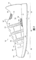
アッパー120のスロート領域124は、カラー123の前方で、主に中足領域102内に位置している。スロート領域124の範囲は変えてもよいが、スロート領域124は、足の甲または上面に対応し、締めひも125と、複数の締めひも収容要素126と、ベロ127とを含んでいる。締めひも125は、いくつかの締めひも収容要素126に係合して、締めひも収容要素126間でジグザグの経路を辿っている。さらに、締めひも125は、スロート領域124の両側間で、スロート領域124を何度も横切っている。
The
履物100を用いた場合、締めひも125は、着用者が、足のサイズに合わせてアッパー120の寸法を変更することを可能にする。より具体的には、締めひも125は、着用者が、(a)アッパー120を足の周りに締め付けること、および(b)アッパー120を緩めて、(カラー123によって形成された開口部を介した)アッパー120内の空洞への足の挿入および空洞からの足の抜き出しを容易にすることを可能にするような従来の方法で扱うことができる。締めひも収容要素126は、アッパー120の開口として図示されており、締めひも125がそれらの開口を通っており、締めひも収容要素126は、ループ、アイレット、フックまたはD字状リングであってもよい。
With the
アッパー120の大部分は、ニット構成要素130および表面層140から形成されており、それらは、図5および図6における履物100の残りの部分とは別に図示されている。ニット構成要素130は、横編みプロセスによって製造してもよく、領域101〜領域103の各々にわたって、外側部104および内側部105の両方に沿って、足先領域101を覆って、およびかかと領域103の周りに及んでいる。ニット構成要素130の部分は、外側面121を形成しているが、ニット構成要素130は、内側面122の大部分または比較的多くの部分を形成し、それによって、アッパー120内の空洞の一部を画成している。いくつかの構造では、ニット構成要素130は、足の下に及んでいてもよい。
Most of the upper 120 is formed from a
さまざまな図における実施例のために、ストローベル式中敷き128がニット構成要素130に固定されて、足の下に広がっているアッパー120の部分の大部分を形成している。この構造では、中敷き113は、ストローベル式中敷き128の上に広がって、足がその上に載る面を形成している。くわえて、図3および図4Cに図示されているように、ニット構成要素130の縁部を接合するために、縫い目129がかかと領域103を通って垂直方向に延びている。
For the embodiments in the various figures, a
表面層140は、ニット構成要素130に隣接して位置し、ニット構成要素130の外側に固定され、それによって、外側面121の大部分または比較的多くの部分を形成している。表面層140を形成するのに、ポリマーシート、革または合成皮革から成る要素、織布または不織布、または金属箔を含むさまざまな材料を用いてもよい。
The
ニット構成要素130と同様に、表面層140は、領域101〜領域103の各々を通って、外側部104および内側部105の両方に沿って、足先領域101を覆って、およびかかと領域103の周りに及んでいる。表面層140は、スロート領域124(例えば、ベロ127)から成る部分および内側面122がないように図示されている。履物100のさらなる構造では、表面層140は、アッパー120の他の領域がなくてもよく、または、スロート領域124の部分を覆って、内側面122内まで及んでいてもよい。
Similar to the
ニット構成要素130と表面層140の組合せは、さまざまな利点を履物100にもたらす。実施例として、ニット構成要素130および表面層140は、ウォーキング、ランニングおよびその他の歩行活動中に、履物100内の足を固定する、比較的きつい、手袋のようなフィット感をアッパー120に付与する。例えば、サッカーシューズとして作られた場合、その比較的きつい、手袋のようなフィット感は、着用者に、ボールの感触およびボールコントロール性を高める。また、表面層140は、アッパー120の領域を補強するのに利用することもできる。例えば、表面層140は、ニット構成要素130の伸縮性を抑えるとともに、アッパー120の耐摩耗性または磨耗耐久性を高めることができる。
The combination of the
また、表面層140は、履物100に耐摩耗性を付与することも可能である。くわえて、この構造で履物100を形成することは、比較的軽い重量または質量、足のためのサポート、均一なフィット感および足の形状に対する適合性、および着用者のための快適性を高めた比較的縫い目のない内部をもたらすことができる。
The
上記の説明は、アッパー120のさまざまな特徴および要素を示している。しかし、履物100のさらなる構造では、(a)安定性を高めるためのかかと領域103内のヒールカウンタ、(b)耐摩耗性材料で形成されている足先領域101内のつま先ガード、および(c)ロゴ、商標、および注意書きや材料情報が記載された札のうちの1つ以上を含んでもよい。したがって、アッパー120は、本願明細書で説明した、および図面に図示されている形状構成および要素に加えて、さまざまな他の形状構成および要素を組み込んでもよい。
The above description illustrates various features and elements of upper 120. However, in a further construction of the
〈ニット構成要素の構造〉
ニット構成要素130は、アッパー120全体に及んでおり、内側面122の大部分を構成し、それによって、アッパー120内の空洞の一部を画成している。ニット構成要素130には縫い目が存在していてもよいが、ニット構成要素130の大部分は、実質的に縫い目のない構造を有している。さらに、ニット構成要素130は、一体ニット構造で形成してもよい。
<Structure of knit component>
The
ニット構成要素(例えば、ニット構成要素130)は、本願明細書において用いる場合、編みプロセスによってワンピース要素として形成された場合の「一体ニット構造」で形成されるものと定義される。すなわち、その編みプロセスは、かなりの追加的な製造工程または製造プロセスを要することなく、ニット構成要素130のさまざまな機能および構造を実質的に生じさせる。ニット構成要素130の部分は、編みプロセスに続いて、互いに接合することができるが(例えば、ニット構成要素130の縁部が、縫い目129として一緒に接合される)、ニット構成要素130は、ワンピースニット要素として形成されているため、依然として一体ニット構造で形成されたままである。
A knit component (e.g., knit component 130), as used herein, is defined as being formed as an "integral knit structure" when formed as a one-piece element by the knitting process. That is, the knitting process substantially produces the various functions and structures of the
さらに、ニット構成要素130は、編みプロセスに続いて、他の要素(例えば、締めひも125、ストローベル式中敷き128、ロゴ、商標、札)が付加された場合も、依然として一体ニット構造で形成されたままである。ニット構成要素130に用いることができるニット構成要素のさまざまな構造の実施例は、Duaに対する特許文献1、Duaらに対する特許文献2、Duaらに対する特許文献3、Duaに対する特許文献4、およびHuffaらに対する特許文献5に開示されており、これらの明細書の各々は、参照によってその全体が本願明細書に組み込まれるものとする。
In addition, the
ニット構成要素130の主要な要素は、ニット要素131とインレイストランド(inlaid strand)132である。ニット要素131は、さまざまなコースおよびウェールを画成する複数の互いにかみ合うループを形成するように(例えば、編み機によって)操作される少なくとも1本のヤーン(yarn)から形成されている。すなわち、ニット要素131は、ニット布地から成る構造を有している。インレイストランド132は、ニット要素131を通って延びており、ニット要素131内のさまざまなループの間を通っている。
The main elements of the
インレイストランド132は、ニット要素131内のコースに沿って大略的に延びているが、インレイストランド132は、ニット要素131内のウェールに沿って延びていてもよい。インレイストランド132の利点は、サポート、安定性および構造を提供することを含む。例えば、インレイストランド132は、アッパー120を足の周りに固定するのを補助し、アッパー120の領域における変形を制限し(例えば、耐伸縮性を付与し)、および締めひも125とともに機能して、履物100のフィット感を高めている。先述され、および本願明細書に組み込まれている、Huffaらに対する特許文献5は、ニット要素131内にインレイストランド132を配置するか、または他の方法で設けるプロセスを含む、ニット構成要素130を形成することができる方法の説明を記載している。
The
ニット要素131は、縫製およびヤーンのさまざまな種類および組合せを組み込んでもよい。縫製に関しては、ニット要素131を形成するヤーンは、ニット要素131の1つの領域に1つの種類の縫製と、ニット要素131の別の領域に別の種類の縫製を有していてもよい。用いる縫製の種類および組合せにより、ニット要素131から成る領域は、例えば、無地のニット構造、メッシュニット構造または畝編み構造を有してもよい。異なる種類の縫製は、ニット要素131の美観、伸縮性、厚さ、通気性および耐摩耗性に影響を及ぼすことがある。すなわち、異なる種類の縫製は、ニット構成要素130の異なる領域に異なる特性を付与することがある。
The
ヤーンに関しては、ニット要素131は、ニット要素131の1つの領域に1つの種類のヤーンと、ニット要素131の別の領域に別の種類のヤーンを有していてもよい。さまざまなデザイン基準により、ニット要素131は、例えば、異なるデニール、材料(例えば、綿、エラステイン、ポリエステル、レーヨン、ウールおよびナイロン)および撚りの程度を有するヤーンを組み込んでもよい。異なる種類のヤーンは、ニット要素131の美観、伸縮性、厚さ、通気性および耐摩耗性を含むニット要素131の物理特性に影響を及ぼすことがある。すなわち、異なる種類のヤーンは、ニット構成要素130の異なる領域に異なる特性を付与することがある。さまざまな種類および組合せの縫製およびヤーンを組合せることにより、ニット要素131から成る各領域は、履物100の快適性、耐久性および性能を高める固有の特性を有することができる。いくつかの構造では、ニット構成要素130を形成するために、異なる色を有する複数のヤーンを用いてもよい。異なる色を有するヤーンをまとめて撚って編んだ場合、ニット構成要素130は、複数の色がアッパー120全体に不規則に分散された杢色の外観を有することができる。
With regard to yarns, the
ニット要素131内の1つ以上のヤーンは、加熱したときに柔らかくなるか、または溶けて、冷却すると固体状態に戻る熱可塑性ポリマー材料によって部分的に形成してもよい。より具体的には、熱可塑性ポリマー材料は、十分な熱にさらされた場合、固体状態から軟化状態または液体状態に移行し、その後、熱可塑性ポリマー材料は、十分に冷却されると、軟化状態または液体状態から固体状態に移行する。このように、熱可塑性ポリマー材料は、多くの場合、2つの対象物または要素を一緒に接合するのに用いられる。この場合、熱可塑性ポリマー材料を含むヤーンは、例えば、(a)そのヤーンの他の部分にヤーンを、(b)他のヤーンにそのヤーンを、(c)ヤーンをインレイストランド132に、または、(d)ニット構成要素130を表面層140に接合するのに用いることができる。
One or more yarns in the
インレイストランド132は、上述したように、ニット要素131を通って延びて、ニット要素131内のさまざまなループ間を通っている。より具体的には、インレイストランド132は、ニット要素131のニット構造内に設けられている。
The inlaid
例えば、図7Aおよび図7Bを参照すると、ニット要素131は、チャネルまたは管状構造を有効に画成する2つの独立して離間された布地層を形成し、また、インレイストランド132は、それらの離間された布地層の間に配置されている。しかし、いくつかの構造では、ニット要素131は、インレイストランド132から成る領域に、単一の布地層から成る構造を有していてもよい。どちらの構造でも、インレイストランド132は、ニット要素131内で、ニット要素131の両面の間に配置されている。インレイストランド132は、主にニット要素131内にあるが、インレイストランド132から成る部分は、可視であってもよく、または、ニット要素131の一方または両方の面に露出していてもよい。
For example, with reference to FIGS. 7A and 7B, the
ニット構成要素130を履物100に組み込んだ場合、インレイストランド132は、大略的に垂直方向に、およびスロート領域124から、ソール構造110がアッパー120に固定される領域まで延びている。より具体的には、インレイストランドは、スロート領域124から、ソール構造110に隣接する領域までニット要素131を何度も通っている。スロート領域124では、インレイストランドは、締めひも収容要素126の周りに延びて、それによって、締めひも125がそこを通るループを形成してもよい。
When the
ニット要素131と比較して、インレイストランド132は、より大きな耐伸縮性を呈していてもよい。すなわち、インレイストランド132は、ニット要素131よりも伸縮性が小さくてもよい。インレイストランド132から成る多くの部分が、スロート領域124からソール構造110に向かって延びていれば、インレイストランド132は、アッパー120のこの領域に耐伸縮性を付与する。さらに、締めひも125に張力をかけると、インレイストランド132に張力を付与することができ、それによって、アッパー120から成る部分をスロート領域124とソール構造110との間に誘導して、足に押し付けてもよい。このように、インレイストランド132は、アッパー120を足の周りに固定するのを補助して履物100のフィット感を高めるように、締めひも122とともに機能する。
Compared to the
インレイストランド132の構造は、大幅に変えてもよい。ヤーンに加えて、インレイストランド132は、例えば、フィラメント(例えば、単繊維)、スレッド、ロープ、帯、ケーブルまたは鎖から成る構造を有してもよい。ニット要素131を形成するヤーンと比較して、インレイストランド132の厚さは、より大きくもよい。いくつかの構造では、インレイストランド132は、ニット要素131のヤーンよりも著しく大きな厚さを有してもよい。
The structure of inlaid
さらに、インレイストランド132を形成する材料は、綿、エラステイン、ポリエステル、レーヨン、ウールおよびナイロン等のニット要素131内のヤーンのための材料のうちのいずれかを含んでもよいが、金属と、ガラス、アラミド(例えば、パラアラミドおよびメタアラミド)、超高分子量ポリエチレンおよび液晶ポリマーを含む、高引張強度用途に利用されるさまざまなエンジニアリングフィラメントとを含んでもよい。別の実施例として、ポリエステル製組糸をインレイストランド132として用いてもよい。
Further, the material forming
ニット構成要素130と表面層140の組合せは、さまざまな利点を履物100にもたらす。しかし、いくつかの構造では、表面層140が履物100になくてもよい。すなわち、ニット構成要素130は、個別に用いてアッパー120の部分を形成してもよく、また、ニット構成要素130は、面121および122の各々の比較的多くの部分の大部分を形成してもよい。さらに、表面層140がない場合の突出領域133の存在は、追加的な厚さまたはロフトをアッパー120に付与することができるとともに、アッパー120の伸縮性を変えることもできる。したがって、ニット構成要素130は、表面層140と組合せて説明したが、単独で用いてもよい。
The combination of the
〈表面層の構造〉
表面層140は、ニット構成要素130に隣接し、外側面121の一部を形成するようにニット構成要素130に固定されている。上述したように、表面層140は、ポリマーシート、革または合成皮革から成る要素、織布または不織布、または金属箔によって形成することができる。表面層140は、ポリマーシートまたは高分子層として形成される場合、まず、例えば、高分子フィルム、ポリマー粉末またはポリマー樹脂としてもよい。これらの構造のいずれかの場合、ポリウレタン、ポリエステル、ポリエステルポリウレタン、ポリエーテルポリウレタンおよびナイロンを含むさまざまな高分子材料を表面層140に用いることができる。ニット構成要素130に接合することができる熱可塑性ポリマーフィラメントを用いた不織布の実施例は、Duaらに対する特許文献6に開示されており、その明細書は、参照によって本願明細書に組み込まれるものとする。さらに、表面層140に関連する追加的な考察は、Duaに対する特許文献7で見つけることができ、その明細書は、参照によって本願明細書に組み込まれるものとする。
<Structure of surface layer>
The
表面層140は、熱硬化性高分子材料によって形成してもよいが、表面層140の多くの構造は、熱可塑性高分子材料(例えば、熱可塑性ポリウレタン)によって形成される。一般的に、熱可塑性高分子材料は、加熱されると、柔らかくなるか、または溶けて、冷却されると、固体状態に戻る。より具体的には、熱可塑性高分子材料は、十分な熱にさらされると、固体状態から軟化状態または液体状態に移行し、その後、十分に冷却されると、熱可塑性高分子材料は、軟化状態または液体状態から固体状態に移行する。このように、熱可塑性高分子材料は、複数のサイクルを介して、溶解、成型、冷却、再溶融、再成型、および再冷却することができる。また、熱可塑性高分子材料は、ニット構成要素130等の繊維要素に熱接合または熱結合してもよい。
The
履物100の多くの構造では、表面層140から成る単一の要素がニット構成要素130全体にわたって固定されて、ニット構成要素130の実質的にすべてを覆っている。しかし、さらなる構造では、表面層140から成る異なる要素を、異なる材料から形成して、ニット構成要素130から成る別々の領域に配置してもよい。すなわち、1つの材料から形成された表面層140の部分を、ニット構成要素130の1つの領域に接合してよく、および別の材料から形成された表面層140の別の部分を、ニット構成要素130の異なる領域に接合してもよい。表面層140を形成する材料を変えることにより、異なる特性を、アッパー120の異なる領域に適用させることができる。他の構成では、表面層140は、ニット構成要素130の特定の領域のみを覆って、それによって、ニット構成要素130の他の領域を露出させたままにしてもよい。そのため、表面層140は、ニット構成要素130のいくつかの領域にはなくてもよい。
In many constructions of the
表面層140は、ニット構成要素130の外側に配置されるものとして上述した。しかし、いくつかの構造では、表面層140は、ニット構成要素130の反対側の面と接合して、それによって、内側面122から成る部分を形成してもよい。他の構成では、2つの表面層140を、ニット構成要素130の両面に接合してもよく、または、表面層140は、ニット構成要素130内に組み込むか、または別の方法でニット構成要素内まで延びていてもよい。
The
〈突出領域〉
ニット構成要素130は、アッパー120内の空洞から離れて外側に延びている複数の突出領域133を含んでいる。突出領域133は、膨らみ、突出部、隆起部、または他の外側に延びている部分をニット構成要素130に形成している。
<Protruding area>
インレイストランド132の場合と同様に、突出領域133のほとんどは、スロート領域124から、ソール構造110がアッパー120に固定されている領域まで、概して垂直方向に延びている。突出領域133のいくつかは、インレイストランド132と一致しており、およびそのインレイストランドを含んでいる。くわえて、突出領域133のいくつかは、2つの他の突出領域133の間で、概して水平方向に延びている。すなわち、水平方向の突出領域133は、2つの垂直方向の突出領域133の間に延び、および実用的には、それらの2つの領域に接合されている。突出領域133は、独特の美観を履物100にもたらすことにくわえて、アッパー120の強度を高めることができ、または、さまざまな異なる特性をアッパー120に付与することができる。
As with the inlaid
表面層140は、突出領域133を覆って延びており、また、突出領域133およびニット構成要素130の他の領域に固定されていてもよい。このように、表面層140は、対応する膨らみ、突出部、隆起部、または、他の外側に延びている部分を、例えば、図7Aおよび図7Cに図示されているように、突出領域133の位置に、および外側面121に形成している。この構造の利点は、履物100の摩擦特性を、突出領域133がアッパー120内に形成する特定のパターンによって制御することができるということである。
The
実施例として、突出領域133と表面層140の組合せは、サッカーというスポーツをしているときのボールのコントロールを高めることができる。すなわち、サッカーのプレーヤーは、突出領域133によって形成されているアッパー120の隆起した、または外側に延びている部分によって、サッカーボールのコントロールを高めることができる。
As an example, the combination of the projecting
突出領域133は、さまざまな構造を有するように形成することができる。すなわち、複数のニット構造および編み方を用いて、突出領域133を形成することができる。
The
実施例として、図8Aおよび図8Bの各々は、突出領域133のための2つの異なる構造を有するアッパー120の例示的な部分を図示している。より具体的には、第1の突出領域133は、第1の管状構造134と、インレイストランド132から成る部分とを含み、また、第2の突出領域133は、第2の管状構造135と、複数のヤーン部分136とを含んでいる。これらの構造の各々を、以下でより詳細に説明する。
By way of example, each of FIGS. 8A and 8B illustrates an exemplary portion of upper 120 having two different structures for protruding
第1の管状構造134は、2つの独立して離間された繊維層137を有するニット構成要素131から成る領域である。第1の管状構造134の縁部領域は、接合されて一体ニット構造で形成されているのに対して、中央領域は、接合されておらず、インレイストランド132がその中に配置されているチャネルを形成している。第1の管状構造134は、突出領域133のうちの1つを単独で形成するのに十分であるが、インレイストランド132の存在が、追加的な厚みをもたらしている。インレイストランド132は、第1の管状構造134を通って長手方向に延びており、それによって、第1の管状構造134の長さに沿って延びている。
The first
第2の管状構造135は、2つの別々の、離間された繊維層138を有するニット構成要素131から成る領域であり、それによって、第1の管状構造134と同様の構造を有している。第2の管状構造135の縁部領域は接合されて、一体ニット構造で形成されているのに対して、中央領域は接合されておらず、複数のヤーン部分136が配置されているチャネルを形成している。第2の管状構造135は、単独で突出領域133のうちの1つを形成するのに十分であるが、ヤーン部分136の存在が、追加的な厚みをもたらしている。
The second
ヤーン部分136は、第2の管状構造135の外側を横切って延びており、それによって、第2の管状構造135の長手方向の長さに沿ってではなく、第2の管状構造135の幅を横切って延びている。ヤーン部分136が固定される方法は変えてもよいが、ヤーン部分136は、図7A、図7C、図8Aおよび図8Bにおいて、互いに横切っているように図示されており、および第2の管状構造135の両側で引き上げ編みを形成していてもよい。すなわち、引き上げ編みは、ヤーン部分136と、第2の管状構造135の両側とを接合してもよい。
The
図8Bの切り欠き領域に図示されているように、突出領域133のうちの1つ(すなわち、水平方向の突出領域133)は、追加的なヤーン部分136を含み、および管状構造134と管状構造135との間に延び、および実用的にはその間で接合し、それによって、第1の管状構造134から第2の管状構造135まで延びている。ヤーン部分136は、第2の管状構造135の幅方向に延びて互いに交差してもよいが、ヤーン部分136は、その他のさまざまな構造を有してもよい。実施例として、ヤーン部分136は、互いに交差せずに、平面内に位置してもよく、または、ヤーン部分136は、長手方向に、第2の管状構造135の長さに沿って延びていてもよい。
As illustrated in the notched area of FIG. 8B, one of the protruding areas 133 (ie, the horizontal protruding area 133) includes an
上述したように、突出領域133は、膨らみ、突出部、隆起部、または他の外側に延びている部分をニット構成要素130に形成している。このように、突出領域133は、ニット構成要素130の他の領域よりも大きな厚さを有するニット構成要素130の部分である。この構造では、ニット構成要素130の大部分または比較的多くの部分は、第1の厚さを有し、また、さまざまな突出領域133は、第2の厚さを有し、第1の厚さは第2の厚さよりも小さい。
As described above, the protruding
ニット構成要素130を形成するのに用いられるニット構造および編み方と、ニット構成要素130に用いられるヤーンとにより、第1の厚さと第2の厚さの違いは、1〜10ミリメートル以上の範囲で変えてもよい。多くの構造では、第1の厚さは、4ミリメートル未満であり、第2の厚さは、第1の厚さよりも少なくとも2ミリメートル以上大きい。
The difference between the first thickness and the second thickness is in the range of 1 to 10 millimeters or more, depending on the knit structure and knitting method used to form the
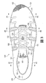
突出領域133がアッパー120に形成している特定のパターンは、かなり変わってもよい。例えば、図1および図2を参照すると、突出領域133は、外側部104および内側部105の大部分を通って延びているが、足先領域101の前方部分と、かかと領域103の後方部分にはない。しかし、突出領域133の配置および構造は、大幅に変えてもよい。
The particular pattern that the raised
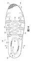
実施例として、図9Aは、さまざまな突出領域133間の間隔が、ニット構成要素130全体にわたって変わっている構造を示す。さらに、他の突出領域133間に延び、およびそれらの他の突出領域に接続している突出領域133がいくつかの領域に存在しているが、その他の領域にはない。突出領域133は、足先領域101に対応するニット構成要素130の領域内には存在しているが、突出領域133は、かかと領域103に対応する領域にはない。この構造では、ニット構成要素131は、スロート領域124に対応する領域を横切って延び、それによって、ベロ127の代わりになっている。
As an example, FIG. 9A shows a structure in which the spacing between the various projecting
図9Bは、突出領域133がニット構成要素130の全体にわたって存在している別の構造を示す。別の構造が図9Cに図示されており、この場合、突出領域133は、インレイストランド132に相当するように配置されているが、他の領域にはない。くわえて、図9A〜図9Cに図示されている構造の各々では、インレイストランド132から成る部分は、締めひも125を受け入れるループを形成するように露出されている。したがって、ニット構成要素130および突出領域133に関するさまざまな態様は、かなり変わってもよい。
FIG. 9B shows another structure in which the protruding
〈接合プロセス〉
ニット構成要素130と表面層140を接合するのに、さまざまなプロセスを用いることができる。いくつかの構造では、表面層140は、熱可塑性高分子材料によって形成してもよく、その表面層は、ニット構成要素130に熱接合または熱結合することができる。上述したように、熱可塑性高分子材料は、加熱されると溶けて、十分に冷却されると、固体状態に戻る。熱可塑性高分子材料のこの特性に基づいて、熱結合プロセスを、表面層140から成る部分をニット構成要素130に接合する熱結合を構成するのに用いてもよい。
Bonding process
Various processes can be used to bond the
「熱結合」またはその変形は、本願明細書において用いる場合、冷却した場合に、2つの要素の材料が互いに固定されるように、それらの要素のうちの少なくとも一方の中での熱可塑性高分子材料の軟化または溶融を伴うそれら2つの要素の間の固定方法として定義される。同様に、「熱接合」という用語、またはその変形は、接合、結び付き、または、冷却された場合に、それらの要素の材料が互いに固定されるように、それらの要素のうちの少なくとも一方の中での熱可塑性高分子材料の軟化または溶融を伴うプロセスによって、2つの要素を接合する構造として定義される。 "Thermal bonding" or a variant thereof, as used herein, is a thermoplastic polymer in at least one of the elements such that the materials of the two elements are fixed to one another when cooled It is defined as the method of fixation between those two elements that involves softening or melting of the material. Similarly, the term "thermal bonding", or variations thereof, may be incorporated into at least one of the elements such that the materials of those elements are secured to one another when joined, joined, or cooled. A process involving the softening or melting of a thermoplastic polymer material at point in time is defined as a structure joining two elements.
実施例として、熱結合は、(a)冷却された場合に、熱可塑性高分子材料がニット構成要素130の材料と混ざって、一緒に固定されるような表面層140の溶融または軟化と、(b)冷却された場合に、熱可塑性高分子材料が、ニット構成要素130の構造内に延びるか、または浸入して(例えば、ニット構成要素130のフィラメントまたは繊維の周りに延びるか、またはそれらのフィラメントまたは繊維に接合する)、それらの要素を一緒に固定するような表面層140の溶融または軟化を伴ってもよい。くわえて、熱結合は、一般に、縫製または接着剤の使用を伴わないが、それらの要素を熱を用いて互いに直接的に接合することを伴う。しかし、いくつかの状況では、熱結合によるそれらの要素の熱接合または接合を補完するために、縫製または接着剤を利用してもよい。
As an example, the thermal bonding may include (a) melting or softening of the
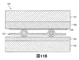
接合プロセスは、図10Aおよび図11Aに図示されているように、第1のプレス部151と第2のプレス部152とを含むプレス150を用いる。プレス部151および152の各々は、ニット構成要素130と表面層140を一緒に圧縮する対向面を有している。プレス部151および152の表面は、実質的に平坦であり、異なる圧縮性を有する材料を含んでいる。
The bonding process uses a
より具体的には、第1のプレス部151は、第1の材料153を含み、第2のプレス部152は、第2の材料154を含んでいる。比較すると、第1の材料153は、第2の材料154よりも大きい圧縮性を有している。適切な材料の例として、(a)第1の材料153はシリコーンであってもよく、および第2の材料154は鋼鉄であってもよく、(b)材料153および154はともにシリコーンであってもよく、第1の材料153は、第2の材料154よりも大きな厚さを有し、または、(c)材料153および154はともに、シリコーンであってもよく、第1の材料153は、第2の材料154よりも小さい密度または硬さを有している。エチルビニルアセテートおよびゴム等のさまざまなポリマーおよび発泡体を含む、その他のさまざまな材料を用いてもよい。しかし、シリコーンの利点は、圧縮歪みに関連している。より具体的には、シリコーンは、圧痕または他の表面むらを形成することなく、多くの圧縮作業を実行することができる。
More specifically, the
次に、ニット構成要素130と表面層140を結合するか、または他の方法で接合するためのプロセスを説明する。その結合プロセスに関連する詳細を説明するために、図8Aおよび図8Bに図示されているニット構成要素130と表面層140とから成る例示的な部分を、図10A〜図10Dおよび図11A〜図11Dで利用する。しかし、当業者は、本願明細書で説明され、および図面に図示されている概念を、ニット構成要素130および表面層140の全体に適用してもよいことを認識するであろう。
A process for bonding or otherwise joining the
再び図10Aおよび図11Aを参照すると、表面層140は、重なった構造でニット構成要素130に隣接して配置されている。表面層140は、第1のプレス部151に隣接して位置しているのに対して、ニット構成要素130は、第2のプレス部152に隣接して位置している。より具体的には、表面層140は、第1の材料153(すなわち、より大きな圧縮性の材料)に接触するように配置され、ニット構成要素130は、第2の材料(すなわち、より小さな圧縮性の材料)に接触するように配置されている。ニット構成要素130および表面層140を正しく配置するために、(a)これらの構成要素を互いに対して保持するジグ、および(b)これらの構成要素を動かすシャトルフレームまたは他の装置の一方または両方を利用してもよい。くわえて、ジグまたは他の装置は、結合プロセス中に、ニット構成要素130が正しい形状を保持して、概して平坦な構造を確実に維持することを支援することができる。
Referring again to FIGS. 10A and 11A, the
プレス150は、ニット構成要素130と表面層140を一緒に圧縮するのに用いられる。しかし、ニット構成要素130および表面層140を結合するために、ニット構成要素130および表面層140の一方または両方は、結合を容易にする温度まで加熱される。プレス部151とプレス部152との間に配置される前に、ニット構成要素130および表面層140を加熱するために、さまざまな輻射ヒータまたは他の装置を用いることができる。しかし、いくつかの製造プロセスでは、プレス150は、プレス150と、ニット構成要素130および表面層140との間の接触が、それらの構成要素の温度を、結合を容易にするレベルまで上昇させるように加熱してもよい。したがって、ニット構成要素130および表面層140の一方または両方が、このプロセス中に加熱される時点は変えてもよい。
The
ニット構成要素130および表面層140が、一旦、配置されると、図10Bおよび図11Bに図示されているように、プレス部151および152は、互いに平行移動して、(a)第1の材料153を有する第1のプレス部151の表面が、表面層140に接触し始めるように、および(b)第2の材料154を有する第2のプレス部152の表面が、ニット構成要素130に接触し始めるように、それらの構成要素を近づける。
Once the
そして、プレス部151および152は、図10Cおよび図11Cに図示されているように、互いに向かってさらに平行移動して、それらの構成要素を完全に圧縮する。この段階で、表面層140は、ニット構成要素130に有効に結合され、または他の方法で接合される。より具体的には、プレス150の圧縮力は、それらの圧縮された構成要素の温度上昇と相まって、ニット構成要素130と表面層140を接合する熱結合を生じさせる。
The
上述したように、第1の材料153は、第2の材料154よりも容易に圧縮される。図10Cおよび図11Cを参照すると、突出領域133に隣接している表面層140から成る領域は、第1の材料153内に圧入され、それに対して、第2の材料154は、より平坦なままであるが、ある程度圧縮される。材料153および154間の異なる圧縮性により、第1の材料153は突出領域133の位置で圧縮される。さらに、(a)ニット構成要素130の突出領域133に接触している表面層140の部分は、第1の材料153によって形成された表面に第1の深さまで突出し、また、(b)ニット構成要素130の他の領域(すなわち、より厚さが小さい領域)と接触している表面層140の部分は、第1の材料153によって形成された表面に第2の深さまで突出し、第1の深さは、第2の深さよりも大きい。
As mentioned above, the
結合が完了すると、図10Dおよび図11Dに図示されているように、プレス150が開いて、結合されたそれらの構成要素が取り外されて冷却できるようになる。このプロセスの最後の工程として、ニット構成要素130および表面層140の組合せを、履物100のアッパー120に組み込んでもよい。
Once bonding is complete, as illustrated in FIGS. 10D and 11D, the
プレス150の表面間に異なる圧縮性を与えるために、材料153および154間の相対的な硬さ、密度および厚さは、かなり変えてもよい。硬さ、密度および厚さを変えることにより、それらの表面の圧縮性を、特定のプレス作業または構造に合わせてもよい。硬さ、密度および厚さをそれぞれ考慮してもよいが、プレス150のいくつかの構造は、硬さが異なるだけの、密度が異なるだけの、または、厚さが異なるだけの材料153および154を有してもよい。
The relative hardness, density and thickness between
くわえて、プレス150のいくつかの構造は、(a)硬さと密度は同じであるが、厚さが異なる、(b)硬さと厚さは同じであるが、密度が異なる、または、(c)密度と厚さは同じであるが、硬さが異なる、材料153および154を有してもよい。したがって、プレス150の表面間で、異なる相対的圧縮性を実現するために、材料153および154のさまざまな特性を、さまざまな方法で変更してもよい。
In addition, some structures of the
材料153および154の各々は、実質的に平坦な表面を有するように図示されている。しかし、ニット構成要素130およびさまざまな突出領域133から成る構造により、材料153および154の表面もそれに合うように形成することができる。例えば、第1の材料153は、突出領域133の位置に一致するさまざまなくぼみまたは圧痕を含んで、それによって、表面層140が突出領域133の周りを覆う程度を大きくしてもよい。
Each of
プレス150は、ニット構成要素130と表面層140を結合するのに用いることができる装置の一実施例を示している。別の実施例として、プレス部151および152のうちの一方を、柔軟な膜と置き換えて、その膜と第2のプレス部152との間から空気を抜くのにポンプを用いてもよい。空気が抜かれるにつれて、膜が表面層140を押し付けて、結合を引き起こすことになる。別の実施例として、ニット構成要素130と表面層140を一緒に圧縮するのに、二重膜システムを用いてもよい。
The
異なる圧縮性を有するように材料153および154を選択するという利点は、突出領域133がもたらすアッパー120の3次元態様に関連している。より具体的には、異なる圧縮性は、ニット構成要素130と表面層140とが圧縮されて結合されたときに、突出領域133が、膨らみ、突出部、隆起部または他の外側に延びている部分を形成し続けることを確実にする。圧縮性材料がない場合、アッパー120が、突出領域133に外側に延びている部分を含む程度は、より小さくてもよい。
The advantage of selecting the
〈足首カフの構造〉
図12〜図15には、着用者の足首の少なくとも一部を覆うための足首カフ160を含む履物100の別の構造が図示されている。そのため、足を覆うことに加えて、アッパー120は、上方に延びて、足首の一部を覆う。
<Structure of ankle cuff>
12-15 illustrate another construction of
参照のために、アッパー120は、図12、図13および図15に示すように、2つの大まかな領域、すなわち、足領域106と足首領域107とに分けることができる。足領域106は、領域101〜領域103の各々を通って延びており、足に一致するアッパー120の部分を大略的に含んでいる。履物100の多くの構造では、足領域106は、着用者の外果および内果(すなわち、足首の各側部の骨の隆起部)の下になるように意図されているアッパー120の部分に相当する。足首領域107は、主にかかと領域103に配置され、足首に一致するアッパー120の部分を大略的に含んでいる。履物100の多くの構造では、足首領域107は、外果および内果を覆って、それらの上に広がるように意図されているアッパー120の部分に相当する。
For reference, the upper 120 can be divided into two broad areas, namely the
足首カフ160は、足首領域107に配置されて、ニット構成要素130の足首部分を形成している。足領域106に位置しているニット構成要素130の残りの部分は、ニット構成要素130の足部分を形成している。ニット構成要素130の足部分が、着用者の足を覆っているのに対して、足首カフ160を含むニット構成要素130の足首部分は、履物100が着用された場合の着用者の足首を覆っている。さらに、足首カフ160と、ニット構成要素130の足首部分は、ニット構成要素130の足部分を有する一体ニット構造で形成してもよい。
The
縫い目129が足首カフ160にあってもよいが、ニット構成要素130の足首部分は、着用者の足首の周り全体に及ぶための連続構造を有している。
Although the
図14の平面図を参照すると、足首カフ160は、アッパー120内の空洞にアクセスできるようにする円形、楕円形または別なふうに連続的で丸みを帯びた開口部161を形成している。開口部161は、足が通過して空洞に入ることを可能にする比較的大きな寸法を有してもよい。しかし、履物100の多くの構造では、開口部161は、足を収容するように伸びる。さらに、足首カフ160は、普通の足首よりも小さい寸法を有していてもよく、また、足首カフ160は、一旦、足が空洞内に配置されると、少し伸びたままで、足首をきつく押し付けてもよい。したがって、足首カフ160と、足首領域107におけるニット構成要素130の他の部分は、伸縮性を有するように形成してもよい。
Referring to the plan view of FIG. 14, the
足首領域107が伸縮性を有しているのに対して、アッパー120の足領域108は、足のサポートをもたらすように、およびソール構造120に対する足の動きを制限するように、ある程度伸びてもよい。すなわち、足領域106は、第1の程度の伸縮性を有し、また、足首領域107は、第2の程度の伸縮性を有してもよく、第1の程度の伸縮性は、第2の程度の伸縮性よりも小さい。いくつかの構造では、領域106および107の両方におけるニット構成要素130の部分は、同様の伸縮性を有してもよく、また、足首領域106におけるインレイストランド132および表面層140の存在が、足首領域106における伸縮性を制限してもよい。他の構造では、ニット構成要素130の足首部分は、伸縮性を付与するヤーンまたはニット構造で形成してもよく、一方、ニット構成要素130の足部分は、より小さな伸縮性を付与するヤーンまたはニット構造によって形成してもよい。
While the
足首カフ160の伸縮性を高めるために、表面層140は、足首領域107になくてもよい。すなわち、表面層140は、ニット構成要素130の足首部分にはなくてもよい。この構造では、足首カフ160を含むニット構成要素130の足首部分は、足首領域107における外側面121および内側面122の部分を形成している。このように、足首カフ160を構成する表面層140およびニット構成要素130の部分は、外側面121の大部分を形成し、また、ニット構成要素130は単独で、内側面122の比較的多くの部分を形成していてもよい。
The
足首カフ160の領域では、表面層140は、側部104および105の各々で下方に延びている凹状縁部141を形成している。より具体的には、表面層140は、外果および内果を覆うニット構成要素130の領域がなくてもよい。この構造の利点は、足首カフ160は、外果および内果上で伸びて、それによって、履物100の快適性を高めることができるということである。他の構造では、表面層140は、外果および内果を覆うように上方へ延びていてもよく、または、縁部141は、足首カフ160の領域では、比較的直線状または凸状であってもよい。
In the area of the
上記の説明に基づいて、足首カフ160は、アッパー120の他の部分よりも大きな伸縮性を呈していてもよい。この構造は、足が履物100に入ることを可能にすることに加えて、足のサポートをもたらし、およびソール構造120に対する足の動きを制限する。くわえて、足首カフ160は、履物100が着用されたときに、伸びた状態のままでもよく、および足首を押し付けてもよく、これらのことは、2つの利点をもたらす。すなわち、第一には、足首カフ160が、ごみ、ほこりおよびその他の破片が履物100に入るのを防ぐ。第二には、着用者は、足首の周りの足首カフ160の存在に気付くことができ、そのことが、着用者の足の固有感覚認識度を高めている。
Based on the above description,
〈締めひもチャネルの構造〉
ベロ127内にいくつかの締めひもチャネル170を含んでいる履物100のさらなる構造が図16および図17に図示されている。締めひも125は、締めひもチャネル170を通り、それによって、締めひも125の部分がベロ127内に配置されている。
<Stretch channel structure>
A further construction of
履物100の残りの部分とは別にベロ127を図示している図18および図19を参照すると、締めひもチャネル170の各々は、履物100の長手方向軸に対して対角線上に向けて配置されている。締めひもチャネル170の位置は、締めひも収容要素126の位置と概して一致しており、およびそのひもが締めひも収容要素126間を通過するように、締めひも125の自然の経路をたどっている。すなわち、締めひもチャネル170の位置および方向は、締めひも収容要素126のうちの2つが、各締めひもチャネル170の両端部に隣接して位置するように選択される。実際には、締めひもチャネル170は、2つの締めひも収容要素126の間に延びるラインに沿って配置される。さらに、締めひも125は、いくつかの締めひもチャネル170を通って延び、および締めひもチャネル170の両端部に配置されている締めひも収容要素126に係合している。このように、締めひも125は、締めひも収容要素126の間でジグザグの経路をたどっている。
Referring to FIGS. 18 and 19 which illustrate the
締めひもチャネル170は、管状構造134および135と同様の構造を有している。このように、締めひもチャネル170は、互いに重なっている、2つの別々で離間された繊維層171を含んでいる。締めひもチャネル170の縁部領域は接合されて、一体ニット構造で形成されているのに対して、中央領域は接合されずに、締めひも125がその中に配置される管状構造を形成している。すなわち、締めひも125は、長手方向で、各締めひもチャネル170を通って延びており、それによって、各締めひもチャネル170の長さに沿って延びている。
The
ベロ127を形成するのに、さまざまな方法を用いてもよいが、編みプロセス(例えば、横編みプロセス)を用いることができる。同様の編みプロセスがベロ127およびニット構成要素130のために用いられる構造では、ベロ127およびニット構成要素130の各々は、同様の特性、材料および外観を有してもよい。くわえて、編みプロセスの利点は、締めひもチャネル170は、ベロ127の残りの部分を有する一体ニット構造で形成することができ、そのことが、効率的な製造をもたらし、および滑らかで縫い目のない構造をベロ127に与える。
Although various methods may be used to form the
ニット構成要素130と締めひも125を組み合わせた構造を図20に示す。図9A〜図9Cの構造と同様に、ニット要素131は、スロート領域124に一致する領域を横切って広がり、それによって、ベロ127の代わりになっている。さらに、ニット要素131は、いくつかの締めひもチャネル170を形成している。ベロ127におけるいくつかの締めひもチャネル170の場合と同様に、この構造における締めひもチャネル170は、互いに重なっている2つの別々の離間された繊維層であり、一体ニット構造で形成され、および締めひも125を収容する。
The combined structure of the
締めひもチャネル170を通って延びている締めひも125が図20に図示されている。締めひも収容要素126を形成する開口に代わって、インレイストランド132が露出されて、締めひも125を収容するためのループを形成している。すなわち、インレイストランド132によって形成されたループが締めひも収容要素126であり、それらは、スロート領域124の両側に設けられている。締めひも125は、(a)インレイストランド132によって形成されたループと、(b)いくつかの締めひもチャネル170を通って延びている。ベロ127と同様に、締めひもチャネル170の各々は、長手方向軸に対して対角線上に向けられて、締めひも125の自然な経路をたどっている。すなわち、締めひもチャネル170の位置および方向は、2つのループが、各締めひもチャネル170の両端部に隣接して位置するように選択される。このように、締めひも125は、インレイストランド132によって形成されたループ間で、ジグザグの経路をたどっている。
A lacing 125 extending through lacing
締めひもチャネル170は、さまざまな長さを有していてもよい。図16において、締めひもチャネル170の端部は、スロート領域124内のニット構成要素130の縁部に隣接して配置されている。ニット構成要素130は、ベロ127の部分に重なっているが、締めひもチャネル170の端部は露出されて、締めひも125を収容する。
The lacing
図20においては、締めひもチャネル170の端部は、締めひも収容要素126を形成しているループに隣接して配置されている。どちらの構造でも、締めひもチャネル170のうちの1つ以上が、3センチメートル以上の長さを有していてもよい。しかし、他の構造では、締めひもチャネル170は、1〜10センチメートル以上の範囲であってもよい。
In FIG. 20, the end of the lacing
スロート領域124に一致する領域において、インレイストランド132によって形成されたループ間にいくつかの開口172を画成している、ニット構成要素130のさらなる構造を図21および図22に示す。開口172は、ニット要素131を通って延びている開口部を形成している。この構造では、締めひも125は、いくつかの開口172を通って延び、また、締めひも125の部分は、ニット要素131の両側に隣接して位置している。より具体的には、締めひも125は、インレイストランド132によって形成されたループを通って延びて開口172に入り、それによって、それらのループ間にある締めひも125の部分を、ニット要素131の両側に隣接して配置する。開口172の位置は、インレイストランド132によって形成されたループの位置に概して一致しており、および締めひも125の自然な経路をたどっている。すなわち、開口172は、インレイストランド132によって形成されたループのうちの2つの間に延びるラインに沿って配置されている。
Additional structures of the
〈追加的な構造〉
履物100、アッパー120、ニット構成要素130および表面層140のさまざまな構造が上述されてきた。しかし、それらの構造は、履物100に組み込んでもよい構造および他の機能の実施例を提供することが意図されている。履物100、アッパー120、ニット構成要素130および表面層140に対する多くの変形が可能であるが、いくつかの追加的な構造を以下に説明する。
<Additional structure>
Various structures of the
履物100の多くの構造では、ニット構成要素130は、内側面122の大部分を形成している。図23および図24を参照すると、ニット構成要素130に固定されて、内側面122の部分を形成している内側層180が図示されている。内側層180は、アッパー120の伸びを抑制することができ、およびアッパー120の耐摩耗性または磨耗耐久性を高めることができる。また、内側層180は、履物100に耐摩耗性を付与してもよい。くわえて、内側層180を含むように履物100を形成すれば、均一なフィット性および足への適合性、着用者に対する快適性が向上した、比較的縫い目のない内部、比較的軽い重量、および足に対するサポートをもたらすことができる。内側層180は、表面層140も含む構造に利用してもよいが、内側層180は、表面層140がない場合に、または、表面層140の代わりとして用いてもよい。
In many constructions of
内側層180は、ニット構成要素130の実質的にすべてを覆って延びていてもよく、または、ニット構成要素130の特定の領域にはなくてもよい。例えば、足先領域101に一致する領域では、内側層180は、アッパー120の伸縮性、柔軟性および通気性を高めることができる複数の開口181を画成している。開口181のサイズ、位置および数を変えることにより、アッパー120の特性を変えてもよい。
The
インレイストランド132に隣接する領域では、内側層180は、より大きな開口を有するように形成され、および中足領域102に一致する領域に柔軟性を促進するとともに、安定性および耐伸縮性ももたらす可能性のある連接構造を有している。また、内側層180のこの部分は、締めひも125が締められたときに、張力を受けて、伸張が抑えられることがある。このように、内側層180とインレイストランド132の組合せは、アッパー120の伸張に対してより大きな抵抗力を付与することができる。かかと領域103に一致する領域では、内側層180は、追加的な耐伸縮性および耐久性をカラー123にもたらすように設けられている。また、内側層180は、ストローベル式中敷き128に接合されているニット構成要素130の縁部まで延びており、そのことが、内側層180をソール構造110に有効に結合または接合することにも留意すべきである。
In the area adjacent to the inlaid
さまざまな材料を内側層180に用いることができる。実施例として、内側層180は、表面層140の特性の多くを備えたポリマー層であってもよい。また、内側層180は、ニット構成要素130に接着されるか、または結合される超極細繊維等の繊維であってもよい。いくつかの構造では、内側層180は、ニット構成要素130に熱結合するための熱可塑性高分子材料を含む多層構造を有していてもよい。
Various materials can be used for the
表面層140は、ニット構成要素130の実質的にすべてを覆っていてもよいが、表面層140は、ニット構成要素130のいくつかの領域にはなくてもよい。上述した実施例に関しては、表面層140は、スロート領域124または足首領域107にはなくてもよい。
The
別の実施例として、図25Aは、中足領域103に対応する領域と、インレイストランド132を含む領域には存在しているが、足先領域101およびかかと領域103に対応する領域にはないような表面層140を示す。さらに、表面層140は、いくつかの突出領域133を覆っているが、他の突出領域133は、露出されたままである。したがって、表面層140は、ニット構成要素130の特定の領域のみを覆って、それによって、ニット構成要素130の他の領域は露出したままにしてもよい。
As another example, FIG. 25A is present in the region corresponding to the
表面層140の単一の要素は、上述した多くの構造において、ニット構成要素130に固定されている。図25Bを参照すると、分割線142が、足先領域101に一致する領域を通って長手方向に延びており、それによって、表面層140の異なる部分を分けている。この構造では、表面層140の各部分は、異なる特性を有してもよい。より具体的には、表面層140を形成する材料、その材料の厚さ、または、他の特性は、表面層140のそれらの部分の間で変えてもよく、それにより、アッパー120の異なる領域に異なる特性を付与してもよい。さらなる構造では、分割線142は、他の領域に設けてもよく、または、表面層140のそれらの部分は、ニット構成要素130の一部を露出させるように、互いに離間していてもよい。
A single element of the
本発明は、さまざまな構造に関して、上記および添付図面に開示されている。しかし、その開示が果たす目的は、本発明に関連するさまざまな特徴および概念の実施例を示すことであり、本発明の範囲を限定することではない。当業者は、添付クレームによって定義される本発明の範囲から逸脱することなく、上述した構造に対してさまざまな変形および変更を行ってもよいことを正しく認識するであろう。 The invention is disclosed above and in the accompanying drawings with respect to various structures. The purpose served by the disclosure, however, is to show examples of various features and concepts related to the present invention, and not to limit the scope of the present invention. Those skilled in the art will appreciate that various modifications and alterations may be made to the structure described above without departing from the scope of the present invention as defined by the appended claims.
本米国特許出願は、2012年11月15日に米国特許商標庁に出願された、「ニット構成要素を組み込んだ履物製品」というタイトルの米国特許仮出願第61/727,010号明細書(代理人明細書番号51−2906)の継続出願であり、およびその出願に対する優先権を主張するものであり、その開示全体は、参照によって本願明細書に組み込まれるものとする。 No. 61 / 727,010, filed on Nov. 15, 2012, entitled “A Footwear Product Incorporating a Knit Component,” filed on Nov. 15, 2012; No. 51-2906) and claim priority to that application, the entire disclosure of which is incorporated herein by reference.
Claims (20)
前記アッパーの内側側部を少なくとも部分的に形作る内側部と、前記アッパーの外側側部を少なくとも部分的に形作る外側部と、前記内側部と前記外側部との間に位置するスロート領域とを含むニット構成要素であって、前記スロート領域は着用者の足の上面に対応するように構成され、前記ニット構成要素が前記スロート領域に締めひもチャネルを画成し、前記スロート領域に、上ニット層および底ニット層の2つの重なっているニット層を含む、ニット構成要素と、
それぞれが前記アッパーの内側側部および外側側部に設けられた複数の締めひも収容要素であって、前記複数の締めひも収容要素のうちの2つが、前記締めひもチャネルの両端部に隣接して配置される、複数の締めひも収容要素と、
前記締めひもチャネルを通って延び、および前記締めひも収容要素のうちの2つに係合する締めひもと、を含み、
前記締めひもチャネルは前記ニット構成要素の前記スロート領域の、前記上ニット層と前記底ニット層との間に埋め込まれている、履物製品。 An article of footwear having an upper, said upper comprising:
It includes an inner portion at least partially defining the inner side of the upper, an outer portion at least partially defining the outer side of the upper, and a throat region located between the inner and outer portions. a knitted component, the throat region is configured to correspond to the upper surface of the wearer's foot, defining a cord channel the knitted component is fastened to the throat region, the throat region, the upper knitted layer A knit component, comprising two overlapping knit layers, and a bottom knit layer;
A plurality of lacing receiving elements respectively provided on the inner side and the outer side of the upper, wherein two of the plurality of lacing receiving elements are adjacent to opposite ends of the lacing channel A plurality of strap receiving elements arranged;
A lacing extending through the lacing channel and engaging two of the lacing receiving elements;
An article of footwear, wherein the lacing channel is embedded between the top and bottom knit layers in the throat area of the knit component.
前記締めひもチャネルは、前記ベロに形成される、請求項1〜請求項3のいずれかに記載の履物製品。 The throat area includes the tongue or tongue of the upper,
The lacing channels are formed before Kibe b, article of footwear according to any one of claims 1 to 3.
前記アッパーの外側側部を少なくとも部分的に形作る外側部と、前記アッパーの内側側部を少なくとも部分的に形作る内側部と、前記外側側部と前記内側側部との間に位置し着用者の足の甲もしくは上面に対応するスロート領域とを含むニット構成要素であって、前記ニット構成要素が、前記スロート領域に、前記履物製品の長手方向軸に対して対角線上に向けて配置される複数の締めひもチャネルを画成し、前記スロート領域に、上ニット層および底ニット層の2つの重なっているニット層を含む、ニット構成要素と、
前記締めひもチャネルを通って延びている締めひもと、を含み、
前記締めひもチャネルは前記ニット構成要素の前記スロート領域の、前記上ニット層と前記底ニット層との間に埋め込まれている、履物製品。 An article of footwear having an upper, said upper comprising:
An outer portion at least partially forming an outer side of the upper, an inner portion at least partially forming an inner side of the upper, and a wearer located between the outer side and the inner side . A plurality of knit components including a throat area corresponding to an instep or upper surface of the foot , wherein the knit components are arranged diagonally to the longitudinal axis of the article of footwear in the throat area A knit component, defining a lacing channel of the and, in the throat area, two overlapping knit layers of a top knit layer and a bottom knit layer;
And a lacing extending through the lacing channel,
An article of footwear, wherein the lacing channel is embedded between the top and bottom knit layers in the throat area of the knit component.
Applications Claiming Priority (5)
| Application Number | Priority Date | Filing Date | Title |
|---|---|---|---|
| US201261727010P | 2012-11-15 | 2012-11-15 | |
| US61/727,010 | 2012-11-15 | ||
| US13/944,717 US20140130375A1 (en) | 2012-11-15 | 2013-07-17 | Article Of Footwear Incorporating A Knitted Component |
| US13/944,717 | 2013-07-17 | ||
| PCT/US2013/068839 WO2014078158A2 (en) | 2012-11-15 | 2013-11-07 | Article of footwear incorporating a knitted component |
Publications (3)
| Publication Number | Publication Date |
|---|---|
| JP2016501067A JP2016501067A (en) | 2016-01-18 |
| JP2016501067A5 JP2016501067A5 (en) | 2016-12-15 |
| JP6529008B2 true JP6529008B2 (en) | 2019-06-12 |
Family
ID=50680259
Family Applications (5)
| Application Number | Title | Priority Date | Filing Date |
|---|---|---|---|
| JP2015542700A Active JP6157634B2 (en) | 2012-11-15 | 2013-11-07 | Footwear products incorporating knit components |
| JP2015542698A Active JP6529008B2 (en) | 2012-11-15 | 2013-11-07 | Footwear incorporating a knit component |
| JP2015542699A Active JP6403218B2 (en) | 2012-11-15 | 2013-11-07 | Footwear products incorporating knit components |
| JP2015542695A Active JP6411356B2 (en) | 2012-11-15 | 2013-11-07 | Footwear products incorporating knit components with internal layer configuration |
| JP2015542701A Active JP6739168B2 (en) | 2012-11-15 | 2013-11-07 | Footwear products incorporating knit components |
Family Applications Before (1)
| Application Number | Title | Priority Date | Filing Date |
|---|---|---|---|
| JP2015542700A Active JP6157634B2 (en) | 2012-11-15 | 2013-11-07 | Footwear products incorporating knit components |
Family Applications After (3)
| Application Number | Title | Priority Date | Filing Date |
|---|---|---|---|
| JP2015542699A Active JP6403218B2 (en) | 2012-11-15 | 2013-11-07 | Footwear products incorporating knit components |
| JP2015542695A Active JP6411356B2 (en) | 2012-11-15 | 2013-11-07 | Footwear products incorporating knit components with internal layer configuration |
| JP2015542701A Active JP6739168B2 (en) | 2012-11-15 | 2013-11-07 | Footwear products incorporating knit components |
Country Status (10)
| Country | Link |
|---|---|
| US (12) | US9398784B2 (en) |
| EP (6) | EP3437504B1 (en) |
| JP (5) | JP6157634B2 (en) |
| KR (7) | KR101898405B1 (en) |
| CN (5) | CN104411196B (en) |
| AR (5) | AR093485A1 (en) |
| BR (5) | BR112015000760B1 (en) |
| HK (5) | HK1205440A1 (en) |
| TW (5) | TWI652998B (en) |
| WO (5) | WO2014078159A2 (en) |
Families Citing this family (116)
| Publication number | Priority date | Publication date | Assignee | Title |
|---|---|---|---|---|
| US7107235B2 (en) | 2000-03-10 | 2006-09-12 | Lyden Robert M | Method of conducting business including making and selling a custom article of footwear |
| US9907359B2 (en) | 2008-05-02 | 2018-03-06 | Nike, Inc. | Lacing system with guide elements |
| US8046937B2 (en) | 2008-05-02 | 2011-11-01 | Nike, Inc. | Automatic lacing system |
| US11206891B2 (en) | 2008-05-02 | 2021-12-28 | Nike, Inc. | Article of footwear and a method of assembly of the article of footwear |
| US11723436B2 (en) | 2008-05-02 | 2023-08-15 | Nike, Inc. | Article of footwear and charging system |
| US9150986B2 (en) | 2011-05-04 | 2015-10-06 | Nike, Inc. | Knit component bonding |
| EP2809191B1 (en) * | 2012-02-04 | 2018-09-26 | Puma Se | Shoe, in particular sports shoe |
| US9076419B2 (en) | 2012-03-14 | 2015-07-07 | Bebop Sensors, Inc. | Multi-touch pad controller |
| US20130255103A1 (en) | 2012-04-03 | 2013-10-03 | Nike, Inc. | Apparel And Other Products Incorporating A Thermoplastic Polymer Material |
| US9398784B2 (en) | 2012-11-15 | 2016-07-26 | Nike, Inc. | Article of footwear incorporating a knitted component |
| US9226548B2 (en) | 2013-01-15 | 2016-01-05 | Nike, Inc. | Spacer textile material with channels having multiple tensile strands |
| US9132601B2 (en) | 2013-01-15 | 2015-09-15 | Nike, Inc. | Spacer textile material with tensile strands having multiple entry and exit points |
| US9474328B2 (en) | 2013-01-15 | 2016-10-25 | Nike, Inc. | Spacer textile material with tensile strands in non-linear arrangements |
| US9241537B2 (en) | 2013-01-15 | 2016-01-26 | Nike, Inc. | Spacer textile material with tensile strands that intersect |
| DE102013207163B4 (en) | 2013-04-19 | 2022-09-22 | Adidas Ag | shoe upper |
| DE102013207156A1 (en) | 2013-04-19 | 2014-10-23 | Adidas Ag | Shoe, in particular a sports shoe |
| US11666113B2 (en) | 2013-04-19 | 2023-06-06 | Adidas Ag | Shoe with knitted outer sole |
| DE102013207155B4 (en) | 2013-04-19 | 2020-04-23 | Adidas Ag | Shoe upper |
| US10645990B2 (en) | 2013-08-19 | 2020-05-12 | Nike, Inc. | Article of footwear with adjustable sole |
| US9491983B2 (en) * | 2013-08-19 | 2016-11-15 | Nike, Inc. | Article of footwear with adjustable sole |
| US10092058B2 (en) | 2013-09-05 | 2018-10-09 | Nike, Inc. | Method of forming an article of footwear incorporating a knitted upper with tensile strand |
| US8701232B1 (en) | 2013-09-05 | 2014-04-22 | Nike, Inc. | Method of forming an article of footwear incorporating a trimmed knitted upper |
| US8997529B1 (en) * | 2014-02-03 | 2015-04-07 | Nike, Inc. | Article of footwear including a monofilament knit element with peripheral knit portions |
| US9145629B2 (en) * | 2014-02-03 | 2015-09-29 | Nike, Inc. | Article of footwear including a monofilament knit element with a fusible strand |
| DE102014202432B4 (en) | 2014-02-11 | 2017-07-27 | Adidas Ag | Improved football boot |
| US10362989B2 (en) * | 2014-06-09 | 2019-07-30 | Bebop Sensors, Inc. | Sensor system integrated with a glove |
| US9510637B2 (en) * | 2014-06-16 | 2016-12-06 | Nike, Inc. | Article incorporating a knitted component with zonal stretch limiter |
| FR3024022B1 (en) | 2014-07-22 | 2017-04-28 | Salomon Sas | FOOTWEAR WITH IMPROVED STRUCTURE |
| US9078488B1 (en) | 2014-09-30 | 2015-07-14 | Nike, Inc. | Article of footwear incorporating a lenticular knit structure |
| US9375046B2 (en) | 2014-09-30 | 2016-06-28 | Nike, Inc. | Article of footwear incorporating a knitted component with inlaid tensile elements and method of assembly |
| US9192204B1 (en) | 2014-09-30 | 2015-11-24 | Nike, Inc. | Article of footwear upper incorporating a textile component with tensile elements |
| US10822728B2 (en) | 2014-09-30 | 2020-11-03 | Nike, Inc. | Knitted components exhibiting color shifting effects |
| DE102014220087B4 (en) | 2014-10-02 | 2016-05-12 | Adidas Ag | Flat knitted shoe top for sports shoes |
| US10182656B2 (en) | 2015-04-13 | 2019-01-22 | Steelcase Inc. | Seating components with laminated bonding material |
| US20160302517A1 (en) * | 2015-04-17 | 2016-10-20 | Wolverine World Wide, Inc. | Sole assembly for an article of footwear |
| EP3294084A4 (en) | 2015-05-08 | 2019-01-16 | Under Armour, Inc. | Footwear including a textile upper |
| US11000095B2 (en) | 2015-06-17 | 2021-05-11 | Nike, Inc. | Knitted member for an article of footwear |
| US9730490B2 (en) | 2015-08-04 | 2017-08-15 | Nike, Inc. | Upper for an article of footwear with auxetic configuration |
| KR20180061154A (en) * | 2015-09-08 | 2018-06-07 | 에이버리 데니슨 리테일 인포메이션 서비시스, 엘엘씨. | Shrink shoes or socks |
| US9888742B2 (en) | 2015-09-11 | 2018-02-13 | Nike, Inc. | Article of footwear with knitted component having plurality of graduated projections |
| US10721997B2 (en) | 2015-09-11 | 2020-07-28 | Nike, Inc. | Method of manufacturing article of footwear with graduated projections |
| TWI569741B (en) * | 2015-09-25 | 2017-02-11 | Yu-Ding Zhou | Decompression soles structure |
| DE102015116398A1 (en) | 2015-09-28 | 2017-03-30 | Visiotex GmbH | Shoe with a textile shaft |
| WO2017095945A1 (en) | 2015-11-30 | 2017-06-08 | Nike Innovate C.V. | Article of footwear and charging system |
| EP3386333B1 (en) | 2015-12-07 | 2023-11-01 | Nike Innovate C.V. | Tunnel spring structures |
| US9980536B2 (en) * | 2016-01-20 | 2018-05-29 | Nike, Inc. | Article of footwear with a tensioning system |
| KR101708018B1 (en) * | 2016-02-16 | 2017-02-17 | 안태훈 | Football Fupport Article and method |
| USD802905S1 (en) * | 2016-03-01 | 2017-11-21 | Nike, Inc. | Shoe upper |
| US10201212B2 (en) * | 2016-03-15 | 2019-02-12 | Nike, Inc. | Article of footwear with a tensioning system including a guide assembly |
| US10034519B2 (en) * | 2016-06-16 | 2018-07-31 | Adidas Ag | UV curable lattice microstructure for footwear |
| CN113261746B (en) * | 2016-07-20 | 2023-02-17 | 耐克创新有限合伙公司 | Shoe plate |
| US11026472B2 (en) * | 2016-07-22 | 2021-06-08 | Nike, Inc. | Dynamic lacing system |
| CN106073026B (en) * | 2016-08-01 | 2018-12-25 | 东莞疆皓塑胶制品有限公司 | Shoes with eyelet structure |
| KR101686896B1 (en) * | 2016-08-31 | 2016-12-15 | 허민수 | Shoes |
| US10844526B2 (en) * | 2016-10-23 | 2020-11-24 | Nike, Inc. | Upper including a knitted component having structures with apertures extending from a surface |
| EP3531857B1 (en) * | 2016-10-26 | 2022-08-17 | NIKE Innovate C.V. | Lacing architecture for automated footwear platform |
| CN110167381B (en) | 2016-11-09 | 2021-11-09 | 耐克创新有限合伙公司 | Textile and article and process for manufacturing textile and article |
| CN110022714B (en) * | 2016-12-02 | 2021-04-27 | 耐克创新有限合伙公司 | Footwear with aligned stretch limiters |
| USD824644S1 (en) | 2016-12-16 | 2018-08-07 | The North Face Apparel Corp. | Footwear article |
| US10316441B2 (en) | 2016-12-16 | 2019-06-11 | The North Face Apparel Corp. | Footwear article including circular knit structures |
| US11408104B2 (en) | 2016-12-16 | 2022-08-09 | The North Face Apparel Corp. | Footwear article including circular knit structures |
| US11224261B2 (en) | 2017-02-10 | 2022-01-18 | Nike, Inc. | Knitted article with at least one scallop element and methods of manufacture |
| JP6826653B2 (en) * | 2017-03-20 | 2021-02-03 | 株式会社アシックス | Shoe upper |
| CN108851328B (en) * | 2017-04-07 | 2020-09-18 | 黎明职业大学 | Basketball shoes with sprain-preventing function |
| EP3987969B1 (en) | 2017-05-30 | 2024-02-21 | Nike Innovate C.V. | Mechanical lock sole structure for braided footwear |
| US20200187595A1 (en) * | 2017-06-27 | 2020-06-18 | Puma SE | Shoe, especially sports shoe |
| DE102017210821A1 (en) | 2017-06-27 | 2018-12-27 | Adidas Ag | Specially-designed braided hose |
| US10711380B2 (en) * | 2017-07-13 | 2020-07-14 | Under Armour, Inc. | Article with embroidered tape segments |
| US11357288B2 (en) * | 2017-07-31 | 2022-06-14 | Nike, Inc. | Upper for an article of footwear |
| CN111920135A (en) * | 2017-08-04 | 2020-11-13 | 耐克创新有限合伙公司 | Article and knitted component formed from knitted component including layered pods |
| US11439201B2 (en) | 2017-08-10 | 2022-09-13 | Nike, Inc. | Pair of asymmetrical footwear articles |
| EP4298945A1 (en) * | 2017-10-19 | 2024-01-03 | NIKE Innovate C.V. | Article with at least two layers |
| DE102017223746B4 (en) * | 2017-12-22 | 2024-03-14 | Adidas Ag | Circular knit shoe upper |
| TWI653948B (en) * | 2018-01-23 | 2019-03-21 | 張中豪 | Method for manufacturing moisture-permeable waterproof shoes |
| US11253029B2 (en) * | 2018-02-09 | 2022-02-22 | Nike, Inc. | Slotted eyelet |
| CN111989427B (en) * | 2018-04-16 | 2022-03-25 | 耐克创新有限合伙公司 | Shoe upper including knit cushioning region and article of footwear incorporating same |
| ES2924819T3 (en) * | 2018-04-26 | 2022-10-11 | Puma SE | Shoe, especially sports shoe |
| US11058175B2 (en) | 2018-05-31 | 2021-07-13 | Nike, Inc. | Intermediate sole structure with siping |
| US11358358B2 (en) | 2018-05-31 | 2022-06-14 | Nike, Inc. | Method of manufacturing an article of footwear with a thermoformed siped sole structure |
| EP3745900A1 (en) | 2018-05-31 | 2020-12-09 | NIKE Innovate C.V. | Article of footwear with thermoformed siped sole structure |
| USD888479S1 (en) | 2018-06-04 | 2020-06-30 | Steelcase Inc. | Chair arm |
| USD891842S1 (en) | 2018-06-04 | 2020-08-04 | Steelcase Inc. | Chair arm |
| FR3082103B1 (en) * | 2018-06-08 | 2020-08-28 | Decathlon Sa | METHOD OF MANUFACTURING A SHOE, AND SHOE LIKELY TO BE OBTAINED BY LEDIT PROCEDE |
| US10786043B2 (en) | 2018-07-03 | 2020-09-29 | Under Armour, Inc. | Article with thermally bonded ribbon structure and method of making |
| US10619280B2 (en) | 2018-07-03 | 2020-04-14 | Under Armour, Inc. | Method of making article with ribbon structure and embroidered edges |
| US10736380B2 (en) | 2018-07-03 | 2020-08-11 | Under Armour, Inc. | Article with ribbon structure and embroidered edges |
| US10736381B2 (en) | 2018-07-03 | 2020-08-11 | Under Armour, Inc. | Article with directional tensioning |
| US10758007B2 (en) * | 2018-07-03 | 2020-09-01 | Under Armour, Inc. | Article with thermally bonded ribbon structure and method of making |
| US10716362B2 (en) | 2018-07-03 | 2020-07-21 | Under Armour, Inc. | Article with ribbon structure having nodes and links |
| WO2020018323A1 (en) * | 2018-07-20 | 2020-01-23 | Nike Innovate C.V. | Article of footwear incorporating knitted components and a receiving strap component |
| CN116195802A (en) * | 2018-07-20 | 2023-06-02 | 耐克创新有限合伙公司 | Upper for an article of footwear having an interior component and a cover |
| US11375774B2 (en) * | 2018-08-09 | 2022-07-05 | Nike, Inc. | Knitted component having a knitted anchor portion |
| CN112955047B (en) | 2018-09-06 | 2022-11-29 | 耐克创新有限合伙公司 | Dynamic lacing system with feedback mechanism |
| IT201800010320A1 (en) * | 2018-11-14 | 2020-05-14 | Geox Spa | Footwear item with removable lining |
| US10993497B2 (en) | 2018-11-15 | 2021-05-04 | Under Armour, Inc. | Article with ribbon loops for string lasting |
| TWI722634B (en) * | 2018-11-30 | 2021-03-21 | 荷蘭商耐克創新有限合夥公司 | Article of footwear and method of manufacturing an article of footwear |
| ES2921906T3 (en) * | 2018-12-19 | 2022-09-02 | Puma SE | Shoe upper, especially for a sports shoe |
| US10455898B1 (en) | 2018-12-21 | 2019-10-29 | Nike, Inc. | Footwear article with tongue reinforcer |
| US10617174B1 (en) | 2018-12-21 | 2020-04-14 | Nike, Inc. | Footwear article with doffing ledge |
| CN113226101B (en) * | 2018-12-27 | 2022-10-18 | 耐克创新有限合伙公司 | Article of footwear and method of manufacturing an article of footwear |
| US11344077B2 (en) * | 2018-12-28 | 2022-05-31 | Nike, Inc. | Footwear article with collar elevator |
| US11480481B2 (en) | 2019-03-13 | 2022-10-25 | Bebop Sensors, Inc. | Alignment mechanisms sensor systems employing piezoresistive materials |
| WO2020220052A2 (en) * | 2019-04-24 | 2020-10-29 | Lemons Nicholas | Channeled shoe sole system |
| WO2020243325A1 (en) * | 2019-05-31 | 2020-12-03 | Nike Innovate C.V. | Upper for an article of footwear having an elastic cable |
| EP3986195A1 (en) * | 2019-06-19 | 2022-04-27 | Nike Innovate C.V. | Knitted component with inserted elements |
| USD935760S1 (en) | 2019-07-23 | 2021-11-16 | Puma SE | Shoe |
| USD932762S1 (en) | 2019-07-23 | 2021-10-12 | Puma SE | Shoe |
| WO2021026030A1 (en) | 2019-08-02 | 2021-02-11 | Nike, Inc. | An upper for an article of footwear |
| JP7128160B2 (en) * | 2019-08-22 | 2022-08-30 | 株式会社アシックス | Shoes and method of manufacturing shoes |
| US11439206B2 (en) * | 2019-12-17 | 2022-09-13 | Under Armour, Inc. | Method of making an article of footwear with braided upper |
| US20210274887A1 (en) * | 2020-03-09 | 2021-09-09 | Nike, Inc. | Upper for an article of footwear having angled tubular knit structures |
| CA3135406A1 (en) * | 2020-10-23 | 2022-04-23 | Tbl Licensing Llc | Stretchable waterproof liner |
| US20220225734A1 (en) * | 2021-01-15 | 2022-07-21 | Puma SE | Article of footwear having a knitted upper |
| WO2022219797A1 (en) * | 2021-04-16 | 2022-10-20 | 株式会社アシックス | Shoe |
| US11877624B2 (en) * | 2021-11-18 | 2024-01-23 | Shimano Inc. | Shoelace arrangement and shoelace guide for shoe |
| US20240081465A1 (en) * | 2022-09-14 | 2024-03-14 | Lululemon Athletica Canada Inc. | Upper for Article of Footwear Incorporating a Knitted Butterfly Workpiece |
Family Cites Families (208)
| Publication number | Priority date | Publication date | Assignee | Title |
|---|---|---|---|---|
| US193240A (en) | 1877-07-17 | Improvement in heel-stiffeners for boots and shoes | ||
| US601192A (en) | 1898-03-22 | Tongue for boots or shoes | ||
| US1215198A (en) | 1916-09-21 | 1917-02-06 | Joseph Rothstein | Cushion instep-raiser. |
| US1597934A (en) | 1922-10-10 | 1926-08-31 | Edwin B Stimpson | Stocking |
| US1902780A (en) | 1930-04-11 | 1933-03-21 | Holden Knitting Co | Knitted lining for rubber footwear and method of making same |
| US1910251A (en) | 1931-12-09 | 1933-05-23 | Reliable Knitting Works | Knitted foot covering and method of making the same |
| US1888172A (en) | 1932-06-06 | 1932-11-15 | Reliable Knitting Works | Knitted footwear and method of making the same |
| US2033096A (en) * | 1934-01-19 | 1936-03-03 | Carter William Co | Plain knitted fabric containing rubber-like strands |
| US2001293A (en) | 1934-02-10 | 1935-05-14 | Wilson Wallace | Knitted stocking foot protector |
| US2047724A (en) | 1934-07-12 | 1936-07-14 | Louis G Zuckerman | Knitted article and method of making same |
| US2009361A (en) | 1934-11-15 | 1935-07-23 | Lawson Knitting Company | Knitted fabric |
| US2049175A (en) | 1935-07-06 | 1936-07-28 | Richard J Regan | Method of making applique shoes |
| US2111472A (en) | 1936-08-13 | 1938-03-15 | William H Horn & Bro Inc | Elastic knit fabric |
| US2147197A (en) * | 1936-11-25 | 1939-02-14 | Hood Rubber Co Inc | Article of footwear |
| US2245235A (en) | 1937-04-06 | 1941-06-10 | John W Herlihy | Method of making shoe parts |
| US2292455A (en) * | 1939-03-23 | 1942-08-11 | Goodrich Co B F | Method of making stretchable footwear |
| US2330199A (en) | 1939-05-22 | 1943-09-28 | Basch Olive Holmes | Knitted article |
| GB538865A (en) | 1939-11-18 | 1941-08-20 | Harold Edmund Brew | Improvements relating to knitted fabrics and manufactured knitted articles |
| US2334659A (en) | 1941-04-19 | 1943-11-16 | Malcolm G Vanarsdale | Footwear |
| US2314098A (en) | 1941-04-26 | 1943-03-16 | Mary C Mcdonald | Method of making shoes |
| US2343390A (en) | 1941-11-26 | 1944-03-07 | United Shoe Machinery Corp | Method of stiffening shoes |
| US2400692A (en) | 1943-03-24 | 1946-05-21 | Theotiste N Herbert | Foot covering |
| US2440393A (en) | 1944-08-18 | 1948-04-27 | Frank W Clark | Process of making last-fitting fabric uppers |
| US2569764A (en) | 1946-07-25 | 1951-10-02 | Boyd Welsh Inc | Initially soft stiffenable material |
| US2538673A (en) | 1949-07-19 | 1951-01-16 | Donahue Paul Ansley | Footwear |
| US2608078A (en) | 1950-01-04 | 1952-08-26 | Munsingwear Inc | Foundation garment and element therefor |
| US2586045A (en) | 1950-06-23 | 1952-02-19 | Hoza John | Sock-type footwear |
| US2581728A (en) | 1950-11-17 | 1952-01-08 | Connecticut Footwear Inc | Retainer-welt slipper sock |
| US2641004A (en) | 1950-12-26 | 1953-06-09 | David V Whiting | Method for producing knitted shoe uppers of shrinkable yarn |
| US2675631A (en) | 1951-02-13 | 1954-04-20 | Doughty John Carr | Footwear article of the slipper-sock type |
| DE870963C (en) | 1951-03-13 | 1953-03-19 | Georg Hofer | Strap for boots, especially for ski boots |
| GB782562A (en) | 1953-09-17 | 1957-09-11 | Theodore Oscar Wegner | Improvements in and relating to boots |
| DE1084173B (en) | 1954-09-18 | 1960-06-23 | Walter Geissler | Shoe upper |
| US2994322A (en) | 1959-01-12 | 1961-08-01 | Charles C Cullen | Protective supporter |
| US2994136A (en) * | 1959-11-25 | 1961-08-01 | Trimfoot Company | Shoe rear quarter and adjacent parts |
| US3425075A (en) | 1965-06-24 | 1969-02-04 | Alan E Murray | Method of making leather footwear |
| GB1223285A (en) | 1967-08-29 | 1971-02-24 | Onitsuka Co | Improvements in shoes |
| DE6944404U (en) | 1969-11-14 | 1970-02-19 | Justus Rieker Co Dr | INNER SHOE FOR BOOTS, IN PARTICULAR SKI BOOTS MADE OF PLASTIC |
| US3704474A (en) | 1971-10-21 | 1972-12-05 | Compo Ind Inc | Method of string-lasting |
| US3766566A (en) | 1971-11-01 | 1973-10-23 | S Tadokoro | Hem forming construction of garments, particularly trousers and skirts |
| US3778856A (en) | 1971-11-05 | 1973-12-18 | Salient Eng Ltd | String lasting |
| CA989720A (en) | 1972-02-07 | 1976-05-25 | Stanislaw B. Berger | Non-woven mixed fibre batts |
| NL7304678A (en) | 1973-04-04 | 1974-10-08 | Non woven stitched fabric - including thermoplastic fibres fused to increase mech resistance | |
| US4211806A (en) | 1973-09-19 | 1980-07-08 | Milliken Research Corporation | Treated fabric structure |
| US3952427A (en) | 1974-05-09 | 1976-04-27 | Von Den Benken Elisabeth | Insole for footwear |
| US4031586A (en) | 1974-05-09 | 1977-06-28 | Von Den Benken Elisabeth | Insole for footwear |
| IT1015280B (en) | 1974-06-21 | 1977-05-10 | Toja E | MACHINE FOR THE ASSEMBLY OF TO UPPER DIRECTLY ON THE ASSEMBLY SHAPES |
| US4027402A (en) | 1976-04-02 | 1977-06-07 | Liu Hsing Ching | Novel educational toy |
| US4053995A (en) | 1976-07-23 | 1977-10-18 | Melvin Shein | Orthopedic shoe |
| US4089069A (en) | 1977-02-11 | 1978-05-16 | Becton, Dickinson And Company | Wearing apparel and method of manufacture |
| US4232458A (en) | 1978-03-13 | 1980-11-11 | Wheelabrator Corp. Of Canada | Shoe |
| GB1603487A (en) | 1978-03-30 | 1981-11-25 | Inmont Corp | Leather like materials |
| CH620953A5 (en) | 1978-04-12 | 1980-12-31 | Dubied & Cie Sa E | |
| US4258480A (en) | 1978-08-04 | 1981-03-31 | Famolare, Inc. | Running shoe |
| US4296559A (en) * | 1978-08-30 | 1981-10-27 | Envoys U.S.A., Inc. | Athletic shoe pocket |
| US4255949A (en) | 1979-08-16 | 1981-03-17 | Thorneburg James L | Athletic socks with integrally knit arch cushion |
| US4222183A (en) * | 1979-10-29 | 1980-09-16 | Haddox Billy J | Athletic shoe |
| US4317292A (en) | 1979-12-04 | 1982-03-02 | Florence Melton | Slipper sock and method of manufacture |
| US4373361A (en) | 1981-04-13 | 1983-02-15 | Thorneburg James L | Ski sock with integrally knit thickened fabric areas |
| IT8121560V0 (en) | 1981-04-23 | 1981-04-23 | Nuova Zarine Costruzione Macch | FOOTWEAR WITH UPPER ZONALLY COVERED BY SYNTHETIC MATERIAL INJECTED STABLY JOINED TO THE CANVAS. |
| US4465448A (en) | 1982-03-19 | 1984-08-14 | Norwich Shoe Co., Inc. | Apparatus for making shoes |
| US5095720A (en) | 1982-07-14 | 1992-03-17 | Annedeen Hosiery Mill, Inc. | Circular weft knitting machine |
| JPS59162041A (en) | 1983-03-04 | 1984-09-12 | アキレス株式会社 | Manufacture of sheet-shaped article |
| US4541196A (en) * | 1983-07-11 | 1985-09-17 | Jershin James T | Fishing rod holder signalling device |
| JPS60260499A (en) | 1984-06-07 | 1985-12-23 | Idemitsu Kosan Co Ltd | Preparation of sic whisker |
| US4662088A (en) | 1985-04-29 | 1987-05-05 | Autry Industries, Inc. | Achilles tendon protection and support pad |
| US4706316A (en) | 1985-11-27 | 1987-11-17 | Giancarlo Tanzi | Method for producing footwear |
| JPS6325004U (en) | 1986-07-31 | 1988-02-18 | ||
| US4756098A (en) | 1987-01-21 | 1988-07-12 | Gencorp Inc. | Athletic shoe |
| US4737396A (en) | 1987-02-04 | 1988-04-12 | Crown Textile Company | Composite fusible interlining fabric |
| US4813158A (en) | 1987-02-06 | 1989-03-21 | Reebok International Ltd. | Athletic shoe with mesh reinforcement |
| US4811500A (en) | 1987-02-06 | 1989-03-14 | L. A. Gear, Inc. | Article of footware having an adjustable instep supporting insert |
| US4750339A (en) | 1987-02-17 | 1988-06-14 | Golden Needles Knitting & Glove Co., Inc. | Edge binding for fabric articles |
| DE3705908A1 (en) | 1987-02-24 | 1988-09-01 | Arova Mammut Ag | PADDED BELT |
| JPH053044Y2 (en) * | 1987-03-24 | 1993-01-26 | ||
| US5152025A (en) | 1988-07-29 | 1992-10-06 | Sergio Hirmas | Method for manufacturing open-heeled shoes |
| WO1990003744A1 (en) | 1988-10-03 | 1990-04-19 | Rbfpt, Inc. | Heat embossed shoes |
| JPH0390665A (en) | 1989-01-06 | 1991-04-16 | Ikenaga:Kk | Pattern making control device of filling knitting machine |
| AU632437B2 (en) * | 1989-06-03 | 1992-12-24 | Puma Aktiengesellschaft Rudolf Dassler Sport | Shoe with a closure device and with an upper made of flexible material |
| DE68926789T2 (en) | 1989-10-18 | 1996-11-14 | Toray Industries | METHOD FOR PRODUCING FABRIC WITH OVERLAPING LAMPS |
| US5192601A (en) | 1991-03-25 | 1993-03-09 | Dicey Fabrics, Incorporated | Dimensionally stabilized, fusibly bonded multilayered fabric and process for producing same |
| AU1977192A (en) * | 1991-06-17 | 1993-01-12 | Puma Aktiengesellschaft Rudolf Dassler Sport | Method of producing a shaped shoe part from a strip of fabric, and a shaped shoe part produced by this method |
| DE69218565T2 (en) | 1991-12-11 | 1997-08-07 | Nitto Boseki Co Ltd | Meltable adhesive yarn and process for its manufacture |
| US5319869A (en) | 1991-12-13 | 1994-06-14 | Nike, Inc. | Athletic shoe including a heel strap |
| JPH06113905A (en) | 1992-02-21 | 1994-04-26 | Daiyu Shoji:Kk | Instep covering material for shoes |
| US5365677A (en) | 1992-06-30 | 1994-11-22 | Dalhgren Raymond E | Footwear for facilitating the removal and dissipation of perspiration from the foot of a wearer |
| US5623840A (en) | 1992-07-08 | 1997-04-29 | Tecnit-Technische Textilien Und Systeme Gmbh | Process for production of weave-knit material |
| JP2568344Y2 (en) * | 1993-04-26 | 1998-04-08 | アキレス株式会社 | Slash molded shoes with excellent fit |
| US5319807A (en) | 1993-05-25 | 1994-06-14 | Brier Daniel L | Moisture-management sock and shoe for creating a moisture managing environment for the feet |
| CH689665A5 (en) | 1993-09-07 | 1999-08-13 | Lange Int Sa | Shoe portion other than the sole, in particular slipper tongue inside ski boot. |
| US6079128A (en) | 1993-11-30 | 2000-06-27 | Bauer Nike Hockey Inc. | Skate boot construction with integral plastic insert |
| US5371957A (en) | 1993-12-14 | 1994-12-13 | Adidas America, Inc. | Athletic shoe |
| US5461884A (en) * | 1994-01-19 | 1995-10-31 | Guilford Mills, Inc. | Warp-knitted textile fabric shoe liner and method of producing same |
| PT746214E (en) | 1994-02-28 | 2000-05-31 | Adam H Oreck | SHOE WITH TUBES FOR ATTACKERS |
| US5535531A (en) | 1994-04-28 | 1996-07-16 | Karabed; Razmik | Shoelace rapid tightening apparatus |
| JPH08109553A (en) | 1994-10-04 | 1996-04-30 | Toho Seni Kk | Foundation cloth for three-layer sheet, its production and three-layer sheet for automobile seat, shoes, bag, pouch, etc., produced by using the three-layer foundation cloth |
| DE19506037A1 (en) | 1995-02-22 | 1996-08-29 | Hoechst Trevira Gmbh & Co Kg | Deformable, heat-stabilizable textile pile goods |
| US20050147787A1 (en) | 2000-08-08 | 2005-07-07 | Bailey Larry M. | Carpet construction and carpet backings for same |
| PT840615E (en) | 1995-04-19 | 2003-10-31 | Robarts John P Res Inst | PROTEIN AND METHODS FOR THEIR USE |
| BR9602748A (en) | 1995-06-13 | 1998-04-22 | Faytex Corp | Footwear frame |
| JPH0947302A (en) * | 1995-08-04 | 1997-02-18 | Mizuno Corp | Shoes having finger crotch partition |
| DE59509754D1 (en) | 1995-08-11 | 2001-11-29 | Alfred Buck | Semi-finished product for composite material |
| US5678325A (en) | 1996-01-11 | 1997-10-21 | Columbia Footwear Corporation | Clog type shoe with a drawstring |
| US5765295A (en) | 1996-01-29 | 1998-06-16 | Polyplex Plastics Of North America Inc. | Two piece shoe bottom construction |
| US5735145A (en) | 1996-05-20 | 1998-04-07 | Monarch Knitting Machinery Corporation | Weft knit wicking fabric and method of making same |
| GB9617547D0 (en) | 1996-08-21 | 1996-10-02 | Rover Group | A disc brake assembly for a motor vehicle |
| DE29616943U1 (en) | 1996-09-28 | 1996-11-21 | Recytex Textilaufbereitung Gmb | Textile fabrics |
| US5729918A (en) | 1996-10-08 | 1998-03-24 | Nike, Inc. | Method of lasting an article of footwear and footwear made thereby |
| US5765296A (en) | 1997-01-31 | 1998-06-16 | Nine West Group, Inc. | Exercise shoe having fit adaptive upper |
| CA2198787A1 (en) | 1997-02-28 | 1998-08-28 | Peter Donnelly | Heat mouldable boot liner |
| DE19728848A1 (en) | 1997-07-05 | 1999-01-07 | Kunert Werke Gmbh | Stocking, etc. |
| JP3044370B2 (en) | 1997-08-21 | 2000-05-22 | 株式会社島精機製作所 | Yarn supply device in flat knitting machine |
| US6032387A (en) | 1998-03-26 | 2000-03-07 | Johnson; Gregory G. | Automated tightening and loosening shoe |
| US5996189A (en) | 1998-03-30 | 1999-12-07 | Velcro Industries B.V. | Woven fastener product |
| JPH11302943A (en) | 1998-04-20 | 1999-11-02 | Masahiko Ueda | Fabric for apparel, braid and production of shape stabilized textile product using the same |
| DE19855542A1 (en) | 1998-12-01 | 2000-06-08 | Keiper Recaro Gmbh Co | Stabilization of a knitted fabric with thermal material |
| US6170175B1 (en) | 1998-12-08 | 2001-01-09 | Douglas Funk | Footwear with internal reinforcement structure |
| US6029376A (en) | 1998-12-23 | 2000-02-29 | Nike, Inc. | Article of footwear |
| US6088936A (en) | 1999-01-28 | 2000-07-18 | Bahl; Loveleen | Shoe with closure system |
| JP2000238142A (en) | 1999-02-22 | 2000-09-05 | Ykk Corp | Reinforcing fiber-contained molding material, manufacture of molding using it and safe shoe toe core |
| US6558784B1 (en) | 1999-03-02 | 2003-05-06 | Adc Composites, Llc | Composite footwear upper and method of manufacturing a composite footwear upper |
| US6151802A (en) | 1999-06-15 | 2000-11-28 | Reynolds; Robert R. | Chain saw protective boot and bootie |
| US6308438B1 (en) | 1999-11-15 | 2001-10-30 | James L. Throneburg | Slipper sock moccasin and method of making same |
| DE10013780C1 (en) | 2000-03-20 | 2001-05-23 | Hartig E Videor Tech | Video surveillance device has first separation plane between dome camera and circuit board device and second separation plane between security housing and carrier flange for circuit board device |
| US6401364B1 (en) | 2000-06-15 | 2002-06-11 | Salomon S.A. | Ventilated shoe |
| US6754983B2 (en) | 2000-07-26 | 2004-06-29 | Nike, Inc. | Article of footwear including a tented upper |
| AU2002211580A1 (en) | 2000-10-10 | 2002-04-22 | Prodesco, Inc. | Stiffened fabric |
| EP1335821A1 (en) | 2000-11-21 | 2003-08-20 | EADS Deutschland GmbH | Technical production method, tension module and sewing material holder for creating textile preforms for the production of fibre-reinforced plastic components |
| FR2818506B1 (en) | 2000-12-22 | 2004-06-18 | Salomon Sa | SHOE |
| US6449879B1 (en) * | 2001-02-02 | 2002-09-17 | Nike, Inc. | Sports shoe with integral tongue and lacing system |
| US6837771B2 (en) | 2001-02-06 | 2005-01-04 | Playtex Apparel, Inc. | Undergarments made from multi-layered fabric laminate material |
| GB0104143D0 (en) * | 2001-02-20 | 2001-04-11 | Courtaulds Textiles Holdings | Knitted fabric |
| JP2002306204A (en) | 2001-04-11 | 2002-10-22 | Mizuno Corp | Shoes for track and field |
| US20030126762A1 (en) | 2002-01-10 | 2003-07-10 | Tony Tseng | Three-dimensional spatial shoe vamp |
| CN2518354Y (en) * | 2002-01-22 | 2002-10-30 | 陈慧玲 | Improved structure of shoes and boots |
| US20030191427A1 (en) | 2002-04-05 | 2003-10-09 | Jay Lisa A. | Breast band for hands-free breast pumping |
| DE10222897B4 (en) | 2002-05-23 | 2017-10-26 | Adidas International Marketing B.V. | shoe |
| US6931762B1 (en) * | 2002-12-18 | 2005-08-23 | Nike, Inc. | Footwear with knit upper and method of manufacturing the footwear |
| GB0229495D0 (en) | 2002-12-18 | 2003-01-22 | Johnston Craig P | Article of footwear |
| US6910288B2 (en) | 2002-12-18 | 2005-06-28 | Nike, Inc. | Footwear incorporating a textile with fusible filaments and fibers |
| JP4505212B2 (en) | 2003-01-10 | 2010-07-21 | 美津濃株式会社 | Shoes and double raschel warp knitted fabric used therefor |
| KR20060014025A (en) | 2003-02-26 | 2006-02-14 | 가부시키가이샤 시마세이키 세이사쿠쇼 | Yarn carrier of weft knitting machine |
| US20040181972A1 (en) * | 2003-03-19 | 2004-09-23 | Julius Csorba | Mechanism of tying of shoes circumferentially embracing the foot within the shoe |
| EP1475006A1 (en) | 2003-05-06 | 2004-11-10 | Cheng-Ming Chen | Sock combined with insole |
| US7047668B2 (en) | 2003-07-24 | 2006-05-23 | Nike, Inc. | Article of footwear having an upper with a polymer layer |
| US6922917B2 (en) | 2003-07-30 | 2005-08-02 | Dashamerica, Inc. | Shoe tightening system |
| US7331127B2 (en) | 2003-09-10 | 2008-02-19 | Dashamerica, Inc. | Reduced skin abrasion shoe |
| US8440055B2 (en) * | 2004-01-30 | 2013-05-14 | Voith Patent Gmbh | Press section and permeable belt in a paper machine |
| ES2267336B1 (en) | 2004-02-13 | 2008-02-16 | Calzados Robusta, S.L. | METATARSIAN PROTECTION FOR SAFETY SHOES. |
| US7347011B2 (en) * | 2004-03-03 | 2008-03-25 | Nike, Inc. | Article of footwear having a textile upper |
| US20070294920A1 (en) | 2005-10-28 | 2007-12-27 | Soft shell boots and waterproof /breathable moisture transfer composites and liner for in-line skates, ice-skates, hockey skates, snowboard boots, alpine boots, hiking boots and the like | |
| US20050273988A1 (en) | 2004-06-11 | 2005-12-15 | Christy Philip T | Lace tightening article |
| US7568298B2 (en) | 2004-06-24 | 2009-08-04 | Dashamerica, Inc. | Engineered fabric with tightening channels |
| US7168188B2 (en) * | 2004-07-15 | 2007-01-30 | Nike, Inc. | Article footwear with removable heel pad |
| USD517297S1 (en) | 2004-08-20 | 2006-03-21 | Adidas International Marketing B.V. | Shoe upper |
| US7793434B2 (en) * | 2004-09-03 | 2010-09-14 | Nike, Inc. | Article of footwear having an upper with a structured intermediate layer |
| US7441348B1 (en) | 2004-09-08 | 2008-10-28 | Andrew Curran Dawson | Leisure shoe |
| US7293371B2 (en) * | 2004-09-22 | 2007-11-13 | Nike, Inc. | Woven shoe with integral lace loops |
| DE602005006090T9 (en) | 2005-01-26 | 2009-09-10 | Lange International S.A. | Two-layer part of a sports shoe with deformation zone |
| US8359769B2 (en) * | 2005-06-02 | 2013-01-29 | The Timberland Company | Chimney structures for footwear |
| US8065818B2 (en) | 2005-06-20 | 2011-11-29 | Nike, Inc. | Article of footwear having an upper with a matrix layer |
| US7637032B2 (en) * | 2005-07-29 | 2009-12-29 | Nike, Inc. | Footwear structure with textile upper member |
| FR2891117B1 (en) * | 2005-09-28 | 2007-12-28 | Salomon Sa | SHOE THAT ENHANCES THE MAINTENANCE OF A HEEL |
| US7478488B1 (en) | 2005-10-31 | 2009-01-20 | Reebok International Ltd. | Inflatable and ventilating upper for an article of footwear |
| EP1972706B1 (en) | 2005-11-17 | 2013-09-04 | Shima Seiki Manufacturing., Ltd. | Weft knitting machine capable of inserting warp and knitting method by that weft knitting machine |
| US7685739B2 (en) | 2006-03-31 | 2010-03-30 | Nike, Inc. | Convertible dance shoe |
| US7849609B2 (en) | 2006-03-31 | 2010-12-14 | Nike, Inc. | Interior and upper members for articles of footwear and other foot-receiving devices |
| US7552547B2 (en) * | 2006-05-03 | 2009-06-30 | Converse, Inc. | Slip on athleisure shoe |
| US8418380B2 (en) | 2006-05-25 | 2013-04-16 | Nike, Inc. | Article of footwear having an upper incorporating a tensile strand with a cover layer |
| US8312645B2 (en) | 2006-05-25 | 2012-11-20 | Nike, Inc. | Material elements incorporating tensile strands |
| US8312646B2 (en) * | 2006-05-25 | 2012-11-20 | Nike, Inc. | Article of footwear incorporating a tensile element |
| US8904671B2 (en) | 2006-05-25 | 2014-12-09 | Nike, Inc. | Footwear incorporating a tensile element with a deposition layer |
| US7543397B2 (en) | 2006-09-28 | 2009-06-09 | Nike, Inc. | Article of footwear for fencing |
| US8225530B2 (en) | 2006-11-10 | 2012-07-24 | Nike, Inc. | Article of footwear having a flat knit upper construction or other upper construction |
| US7774956B2 (en) | 2006-11-10 | 2010-08-17 | Nike, Inc. | Article of footwear having a flat knit upper construction or other upper construction |
| GB0701927D0 (en) | 2007-02-01 | 2007-03-14 | Stretchline Holdings Ltd | Fabric |
| US20080189830A1 (en) | 2007-02-14 | 2008-08-14 | Colin Egglesfield | Clothing with detachable symbols |
| US20080313939A1 (en) | 2007-06-25 | 2008-12-25 | Ardill William D | Identification of personnel attending surgery or medical related procedure |
| MX2010002835A (en) | 2007-09-12 | 2010-04-30 | Maidenform Inc | Fabric having a thermoplastic fusible yarn, process of making a fabric containing a thermoplastic fusible yarn, and fabric article formed with a fabric containing a thermoplastic fusible yarn. |
| US8037621B2 (en) * | 2007-09-13 | 2011-10-18 | Nike, Inc. | Article of footwear including a woven strap system |
| US8122616B2 (en) | 2008-07-25 | 2012-02-28 | Nike, Inc. | Composite element with a polymer connecting layer |
| US8347438B2 (en) | 2008-09-29 | 2013-01-08 | Nike, Inc. | Footwear uppers and other textile components including reinforced and abutting edge joint seams |
| US8490299B2 (en) | 2008-12-18 | 2013-07-23 | Nike, Inc. | Article of footwear having an upper incorporating a knitted component |
| US20100199406A1 (en) | 2009-02-06 | 2010-08-12 | Nike, Inc. | Thermoplastic Non-Woven Textile Elements |
| CN101507541A (en) | 2009-04-02 | 2009-08-19 | 冯金玲 | Threading fork-shape structure for positioning shoes-tong of gym shoes |
| US8388791B2 (en) | 2009-04-07 | 2013-03-05 | Nike, Inc. | Method for molding tensile strand elements |
| US8132340B2 (en) * | 2009-04-07 | 2012-03-13 | Nike, Inc. | Footwear incorporating crossed tensile strand elements |
| WO2011004422A1 (en) * | 2009-07-06 | 2011-01-13 | 株式会社アシックス | Shoe with shoelace fastener fitting structure |
| US8474157B2 (en) | 2009-08-07 | 2013-07-02 | Pierre-Andre Senizergues | Footwear lacing system |
| DE102009028627B4 (en) * | 2009-08-18 | 2019-12-19 | Adidas Ag | Sports Shoe |
| US8266827B2 (en) | 2009-08-24 | 2012-09-18 | Nike, Inc. | Article of footwear incorporating tensile strands and securing strands |
| JP4886922B2 (en) | 2009-09-28 | 2012-02-29 | 美津濃株式会社 | Upper structure for football shoes |
| US9295298B2 (en) | 2009-10-07 | 2016-03-29 | Nike, Inc. | Footwear uppers with knitted tongue elements |
| US9149086B2 (en) | 2009-10-07 | 2015-10-06 | Nike, Inc. | Article of footwear having an upper with knitted elements |
| US8429835B2 (en) | 2009-10-21 | 2013-04-30 | Nike, Inc. | Composite shoe upper and method of making same |
| US10716357B2 (en) | 2010-01-04 | 2020-07-21 | Applied Ft Composite Solutions Inc. | Unibody construction footwear and method for making the same |
| US8973288B2 (en) * | 2010-07-30 | 2015-03-10 | Nike, Inc. | Footwear incorporating angled tensile strand elements |
| US20120204448A1 (en) * | 2011-02-10 | 2012-08-16 | Christina Bracken | Minimal Footwear |
| US8839532B2 (en) | 2011-03-15 | 2014-09-23 | Nike, Inc. | Article of footwear incorporating a knitted component |
| US8522577B2 (en) * | 2011-03-15 | 2013-09-03 | Nike, Inc. | Combination feeder for a knitting machine |
| US8869430B2 (en) | 2011-03-16 | 2014-10-28 | Nike, Inc. | Method of manufacturing a contoured fluid-filled chamber with tensile structures |
| US8800172B2 (en) | 2011-04-04 | 2014-08-12 | Nike, Inc. | Article of footwear having a knit upper with a polymer layer |
| EP2693904A4 (en) | 2011-04-08 | 2015-01-07 | Dashamerica Inc Dba Pearl Izumi Usa Inc | Seamless upper for footwear and method for making the same |
| US8844167B2 (en) | 2011-07-18 | 2014-09-30 | Nike, Inc. | Article of footwear having an upper with cord elements |
| US8448474B1 (en) * | 2012-02-20 | 2013-05-28 | Nike, Inc. | Article of footwear incorporating a knitted component with a tongue |
| DE102012206062B4 (en) | 2012-04-13 | 2019-09-12 | Adidas Ag | SHOE UPPER PART |
| US9398784B2 (en) | 2012-11-15 | 2016-07-26 | Nike, Inc. | Article of footwear incorporating a knitted component |
| US20150059209A1 (en) | 2013-08-29 | 2015-03-05 | Nike, Inc. | Article Of Footwear Incorporating A Knitted Component With An Integral Knit Ankle Cuff |
-
2013
- 2013-07-17 US US13/944,675 patent/US9398784B2/en active Active
- 2013-07-17 US US13/944,689 patent/US20140130374A1/en not_active Abandoned
- 2013-07-17 US US13/944,717 patent/US20140130375A1/en not_active Abandoned
- 2013-07-17 US US13/944,638 patent/US20140130373A1/en not_active Abandoned
- 2013-08-29 US US14/013,402 patent/US20140130376A1/en not_active Abandoned
- 2013-11-07 KR KR1020177017553A patent/KR101898405B1/en active IP Right Grant
- 2013-11-07 EP EP18195991.7A patent/EP3437504B1/en active Active
- 2013-11-07 CN CN201380036355.XA patent/CN104411196B/en active Active
- 2013-11-07 WO PCT/US2013/068841 patent/WO2014078159A2/en active Application Filing
- 2013-11-07 EP EP13811639.7A patent/EP2919607B1/en active Active
- 2013-11-07 BR BR112015000760-0A patent/BR112015000760B1/en not_active IP Right Cessation
- 2013-11-07 CN CN201380036353.0A patent/CN104427897B/en active Active
- 2013-11-07 EP EP13808282.1A patent/EP2919606B1/en active Active
- 2013-11-07 JP JP2015542700A patent/JP6157634B2/en active Active
- 2013-11-07 EP EP13812216.3A patent/EP2919611B1/en active Active
- 2013-11-07 JP JP2015542698A patent/JP6529008B2/en active Active
- 2013-11-07 KR KR1020147036094A patent/KR101700023B1/en active IP Right Grant
- 2013-11-07 EP EP13854208.9A patent/EP2919609B1/en active Active
- 2013-11-07 KR KR1020147031827A patent/KR101682785B1/en active IP Right Grant
- 2013-11-07 KR KR1020147031620A patent/KR101742366B1/en active IP Right Grant
- 2013-11-07 WO PCT/US2013/068839 patent/WO2014078158A2/en active Application Filing
- 2013-11-07 JP JP2015542699A patent/JP6403218B2/en active Active
- 2013-11-07 WO PCT/US2013/068845 patent/WO2014078161A2/en active Application Filing
- 2013-11-07 KR KR1020177018005A patent/KR101856918B1/en active IP Right Grant
- 2013-11-07 BR BR112014026945-9A patent/BR112014026945B1/en not_active IP Right Cessation
- 2013-11-07 EP EP13815869.6A patent/EP2919608B1/en active Active
- 2013-11-07 KR KR1020147031944A patent/KR20150005617A/en active Application Filing
- 2013-11-07 CN CN201380036317.4A patent/CN104684433B/en active Active
- 2013-11-07 CN CN201380036401.6A patent/CN105188441B/en active Active
- 2013-11-07 BR BR112014032696-7A patent/BR112014032696B1/en not_active IP Right Cessation
- 2013-11-07 JP JP2015542695A patent/JP6411356B2/en active Active
- 2013-11-07 KR KR1020147032681A patent/KR101754366B1/en active IP Right Grant
- 2013-11-07 WO PCT/US2013/068830 patent/WO2014078152A2/en active Application Filing
- 2013-11-07 WO PCT/US2013/068843 patent/WO2014078160A2/en active Application Filing
- 2013-11-07 BR BR112014027028-7A patent/BR112014027028B1/en not_active IP Right Cessation
- 2013-11-07 BR BR112014028914-0A patent/BR112014028914B1/en not_active IP Right Cessation
- 2013-11-07 JP JP2015542701A patent/JP6739168B2/en active Active
- 2013-11-07 CN CN201380035700.8A patent/CN104470390B/en active Active
- 2013-11-14 AR ARP130104190A patent/AR093485A1/en active IP Right Grant
- 2013-11-14 AR ARP130104192A patent/AR093487A1/en active IP Right Grant
- 2013-11-14 AR ARP130104189A patent/AR093484A1/en active IP Right Grant
- 2013-11-14 AR ARP130104193A patent/AR093488A1/en active IP Right Grant
- 2013-11-14 AR ARP130104191A patent/AR093486A1/en active IP Right Grant
- 2013-11-15 TW TW102141570A patent/TWI652998B/en active
- 2013-11-15 TW TW102141568A patent/TWI646910B/en active
- 2013-11-15 TW TW102141567A patent/TWI646913B/en active
- 2013-11-15 TW TW102141571A patent/TWI663928B/en active
- 2013-11-15 TW TW102141569A patent/TWI646911B/en active
-
2014
- 2014-05-09 US US14/273,605 patent/US9095187B2/en active Active
- 2014-05-09 US US14/273,591 patent/US20140245637A1/en not_active Abandoned
- 2014-05-09 US US14/273,709 patent/US8881430B2/en active Active
- 2014-05-09 US US14/273,574 patent/US8898932B2/en active Active
- 2014-05-09 US US14/273,582 patent/US9642413B2/en active Active
- 2014-09-29 US US14/499,758 patent/US9538804B2/en active Active
- 2014-10-23 US US14/522,265 patent/US9622536B2/en active Active
-
2015
- 2015-06-25 HK HK15106076.7A patent/HK1205440A1/en unknown
- 2015-06-25 HK HK15106073.0A patent/HK1205438A1/en unknown
- 2015-06-25 HK HK15106075.8A patent/HK1205439A1/en unknown
- 2015-11-02 HK HK15110801.1A patent/HK1209986A1/en unknown
-
2016
- 2016-02-24 HK HK16102105.0A patent/HK1214099A1/en unknown
Also Published As
Similar Documents
| Publication | Publication Date | Title |
|---|---|---|
| JP6529008B2 (en) | Footwear incorporating a knit component |
Legal Events
| Date | Code | Title | Description |
|---|---|---|---|
| A521 | Request for written amendment filed |
Free format text: JAPANESE INTERMEDIATE CODE: A523 Effective date: 20161026 |
|
| A621 | Written request for application examination |
Free format text: JAPANESE INTERMEDIATE CODE: A621 Effective date: 20161026 |
|
| A977 | Report on retrieval |
Free format text: JAPANESE INTERMEDIATE CODE: A971007 Effective date: 20171214 |
|
| A131 | Notification of reasons for refusal |
Free format text: JAPANESE INTERMEDIATE CODE: A131 Effective date: 20171221 |
|
| A521 | Request for written amendment filed |
Free format text: JAPANESE INTERMEDIATE CODE: A523 Effective date: 20180316 |
|
| A131 | Notification of reasons for refusal |
Free format text: JAPANESE INTERMEDIATE CODE: A131 Effective date: 20180816 |
|
| A521 | Request for written amendment filed |
Free format text: JAPANESE INTERMEDIATE CODE: A523 Effective date: 20181105 |
|
| TRDD | Decision of grant or rejection written | ||
| A01 | Written decision to grant a patent or to grant a registration (utility model) |
Free format text: JAPANESE INTERMEDIATE CODE: A01 Effective date: 20190418 |
|
| A61 | First payment of annual fees (during grant procedure) |
Free format text: JAPANESE INTERMEDIATE CODE: A61 Effective date: 20190507 |
|
| R150 | Certificate of patent or registration of utility model |
Ref document number: 6529008 Country of ref document: JP Free format text: JAPANESE INTERMEDIATE CODE: R150 |
|
| R250 | Receipt of annual fees |
Free format text: JAPANESE INTERMEDIATE CODE: R250 |
|
| R250 | Receipt of annual fees |
Free format text: JAPANESE INTERMEDIATE CODE: R250 |