JP6524397B2 - Wave power generation turbine - Google Patents
Wave power generation turbine Download PDFInfo
- Publication number
- JP6524397B2 JP6524397B2 JP2014084567A JP2014084567A JP6524397B2 JP 6524397 B2 JP6524397 B2 JP 6524397B2 JP 2014084567 A JP2014084567 A JP 2014084567A JP 2014084567 A JP2014084567 A JP 2014084567A JP 6524397 B2 JP6524397 B2 JP 6524397B2
- Authority
- JP
- Japan
- Prior art keywords
- turbine
- power generation
- wave power
- blade
- flow
- Prior art date
- Legal status (The legal status is an assumption and is not a legal conclusion. Google has not performed a legal analysis and makes no representation as to the accuracy of the status listed.)
- Active
Links
Images


Classifications
-
- Y—GENERAL TAGGING OF NEW TECHNOLOGICAL DEVELOPMENTS; GENERAL TAGGING OF CROSS-SECTIONAL TECHNOLOGIES SPANNING OVER SEVERAL SECTIONS OF THE IPC; TECHNICAL SUBJECTS COVERED BY FORMER USPC CROSS-REFERENCE ART COLLECTIONS [XRACs] AND DIGESTS
- Y02—TECHNOLOGIES OR APPLICATIONS FOR MITIGATION OR ADAPTATION AGAINST CLIMATE CHANGE
- Y02E—REDUCTION OF GREENHOUSE GAS [GHG] EMISSIONS, RELATED TO ENERGY GENERATION, TRANSMISSION OR DISTRIBUTION
- Y02E10/00—Energy generation through renewable energy sources
- Y02E10/30—Energy from the sea, e.g. using wave energy or salinity gradient
Landscapes
- Turbine Rotor Nozzle Sealing (AREA)
- Other Liquid Machine Or Engine Such As Wave Power Use (AREA)
Description
本発明は、波浪エネルギーを利用して発電を行う波力発電装置、特に振動水柱形波力発電装置に利用されるタービンに関するものである。 The present invention relates to a wave power generation device that generates electric power using wave energy, and more particularly to a turbine used for an oscillating water column wave power generation device.
振動水柱形波力発電装置は、下部が海面に開放され、上部が大気への空気通路を有する外部密閉室からなる空気室と、空気通路内に設けられたタービンと、タービンの回転により発電を行う発電機とから構成される。海面の上下運動により空気室内外の圧力差が生じると、その圧力差によって空気通路内に空気流が発生し、この空気流を利用してタービンを回し、発電が行われるようになっている。 The oscillating water column type wave power generator has an air chamber consisting of an external sealed chamber whose lower part is open to the sea surface and whose upper part has an air passage to the atmosphere, a turbine provided in the air passage, and power generation by rotation of the turbine. It consists of a generator to do. When the pressure difference between the inside and the outside of the air chamber is generated by the vertical movement of the sea surface, an air flow is generated in the air passage by the pressure difference, and the turbine is rotated using this air flow to generate power.
この発電装置は、可動部が波浪エネルギーを直接受けないため、構造上強度の問題が少ないという特徴があり、メインテナンス上も有利であることから、離島などの電力供給源として有望視されている。 This power generation apparatus is characterized as having less structural strength problems because the movable part does not receive wave energy directly, and is also advantageous in terms of maintenance, so it is considered promising as a power supply source such as remote islands.
従来から、振動水柱形発電装置のタービンとしては、主にウェルズタービンが用いられてきた(特許文献1)。 Conventionally, a Wells turbine has been mainly used as a turbine of a vibrating water column type power generator (Patent Document 1).
ウェルズタービンは、零揚力面が回転軸に対して垂直となるように取付けられた複数の対称翼型のタービンブレードを有するロータハブを備え、空気流の流れ方向にかかわらず同一方向に回転するように構成されたタービンである。ウェルズタービンは、往復流に対して一方向に駆動力を発生するため、構造が簡単であるという特徴を有する。 The Wells turbine includes a rotor hub having a plurality of symmetrical airfoil turbine blades mounted with their zero lift surfaces perpendicular to the axis of rotation, so that they rotate in the same direction regardless of the airflow direction. It is a configured turbine. The Wells turbine is characterized by its simple structure because it generates a driving force in one direction with respect to the reciprocating flow.
その一方で、ウェルズタービンは、駆動力が揚力に比べて小さく出力トルクが小さいため、起動時間がかかる。また、迎え角の大きい範囲では失速域が存在する。すなわち、海面の上下運動エネルギーから変換された空気流の流量が増加した場合、タービンブレードが失速して、タービントルクの大幅な降下が発生するため、タービン効率が低下するという問題がある。 On the other hand, in the Wells turbine, since the driving force is small compared to the lifting force and the output torque is small, the start-up time is required. In addition, there is a stall region in the range where the angle of attack is large. That is, when the flow rate of the air flow converted from the vertical kinetic energy of the sea surface is increased, the turbine blade is stalled to cause a significant drop of the turbine torque, resulting in a problem that the turbine efficiency is lowered.
上記ウェルズタービンの有する課題を解決するために、従来からさまざまな改善策が講じられてきた。 In order to solve the problems of the Wells turbine, various improvements have been conventionally taken.
例えば、特許文献2には、タービンブレード21の上流側および下流側に、タービンブレードから隔てられた案内羽根22,23が組み込まれたタービンが開示されている(図7参照)。特許文献2に記載されたタービンでは、案内羽根22,23が、タービンブレード流を減少させあるいは消失させるように傾斜させて配設されているため、タービンブレードの失速を低減することができる。しかしながら、特許文献2に開示されたタービンでは、構造が複雑になり、しかも案内羽根22,23の形状の最適化など設計上の問題もある。
For example,
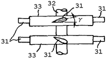
また、特許文献3には、出力軸32に2個のロータハブ33を互いに平行に離間するように固着し、このロータハブ33の周囲に複数のタービンブレード31をロータハブ33の軸線方向に交差する方向で同軸に二列に整列するように配設されており、二列の対称翼型タービンブレード31を互いに後縁が向かい合うように取付け角度γで対称に配設した対称翼型複葉式ウェルズタービンが開示されている(図8参照)。特許文献3に記載されたタービンでは、タービンブレード31を互いに後縁が向かい合うように取付けられているため、起動特性および平均効率を向上させることが可能である。しかしながら、特許文献3に記載されたタービンにおいても、構造が複雑になるとともに、取付け角度γの最適化など設計上の問題がある。
Further, according to
さらに、特許文献4には、回転翼43をその取付け軸周りに同時に回転可能に設け、気体の流速および回転翼43の回転数に応じて、複数の回転翼43の軸周りの回動角度を制御する波力発電タービンが開示されている(図9参照)。特許文献4に記載されたタービンによれば、脈動する気体の流速に応じて、タービンの翼を適正な角度に制御できるので、高いタービン効率で運転できる範囲が拡大され、発電効率の向上を図ることができる。しかしながら、特許文献4に記載されたタービンにおいても、気体の往復流を検知する手段や、回転翼43の回転数を検知する手段が必要となり、構造がさらに複雑になる。しかも、回転翼43を回動させるための動力源などが必要となり、発電した電力を消費してしまうため、装置全体としての発電効率が低下するという問題もある。
Further, in
以上の通り、従来の波力発電タービンでは、いずれも構造が複雑になる。特に、離島で設置される波力発電装置では、メンテナンスフリーであることが要求され、構造の複雑化によって故障頻度が高くなることは、極力避けなければならない。 As described above, in the conventional wave power generation turbine, the structure becomes complicated. In particular, in a wave power generator installed on a remote island, it is required to be maintenance free, and it is necessary to avoid that the failure frequency becomes high due to the complication of the structure as much as possible.
本発明は、波力発電装置に利用される波力発電タービンにおいて、構造が簡単であるという長所を活かしつつ、タービンブレードの失速を低減して、タービン効率を向上させることを目的とするものである。 An object of the present invention is to improve turbine efficiency by reducing the stall of a turbine blade while taking advantage of the simple structure in a wave power generation turbine used for a wave power generation device. is there.
上記課題を解決するために、本発明は、円筒風洞内に配置され、円筒風洞と同心軸線上に回転自在に支持された回転軸と、回転軸に固着され、半径方向に向かって延在する複数のタービンブレードを有するロータハブとを備え、タービンブレードは、その全長Lに対して、ブレード根元から長さ0.75L以上の箇所で、厚さが漸次先細り状に形成されたことを特徴とする。 In order to solve the above-mentioned problems, according to the present invention, a rotary shaft disposed in a cylindrical wind tunnel and rotatably supported coaxially with the cylindrical wind tunnel and fixed to the rotary shaft and extends in a radial direction And a rotor hub having a plurality of turbine blades, wherein the turbine blades are characterized in that the thickness is formed to be gradually tapered at a length of 0.75 L or more from the blade root with respect to the entire length L thereof. .
本発明による波力発電タービンは、円筒空洞の内壁と、ブレード先端との間隙を通過する翼端漏れ流れが減少し、翼端漏れ流れにより形成される翼端漏れ渦を減少させることができる。また、タービンブレードの前方を通過した空気流がタービンブレード4の下流側表面から剥離するのを抑制し、タービンブレードの失速を防止することができる。さらに、タービン効率を向上させることができる。
The wave power generation turbine according to the present invention can reduce the tip leakage flow passing through the gap between the inner wall of the cylindrical cavity and the blade tip, and can reduce the tip leakage vortex formed by the tip leakage flow. In addition, it is possible to suppress the air flow that has passed through the front of the turbine blade from coming off from the downstream surface of the
本発明の実施の形態を図面に基づいて説明する。図1は、波力発電タービンの斜視図、図2は、本発明に係る波力発電タービンのタービンブレードおよび空気流の流れを示す斜視図、図3は、図2のA矢視図、図4は、従来の波力発電タービンのタービンブレードおよび空気流の流れを示す斜視図、図5は、図4のB矢視図、図6は、従来の波力発電タービンの構成および空気流の流れを示す斜視図である。 An embodiment of the present invention will be described based on the drawings. 1 is a perspective view of a wave power generation turbine, FIG. 2 is a perspective view showing the flow of turbine blades and air flow of the wave power generation turbine according to the present invention, and FIG. 3 is a view as viewed from arrow A in FIG. 4 is a perspective view showing the flow of turbine blades and air flow of the conventional wave power generation turbine, FIG. 5 is a view as seen from the arrow B in FIG. 4, and FIG. 6 is the configuration and air flow of the conventional wave power generation turbine It is a perspective view which shows a flow.
図1において、1は、空気室(図示せず)と外気との間で空気が出入りするための円筒風洞(空気通路)、2は、ロータハブ、3は、円筒風洞1内に回転自在に支持されるとともにロータハブ2に固着された回転軸、4は、ロータハブ3から半径方向に延在する対称翼型のタービンブレード、5は、回転軸3に連結され発電機であり、6は、円筒風洞1内に発生する空気流(往復流)、7は、波力発電タービンの回転方向を示している。
In FIG. 1, 1 is a cylindrical air tunnel (air passage) for air to enter and exit between an air chamber (not shown) and the outside air, 2 is a rotor hub, and 3 is rotatably supported in the
海面の上下運動により、空気室(図示せず)の内外で圧力差が生じると、その圧力差によって、円筒風洞1内に空気流6が発生する。空気流6により、タービンブレード4が回転方向7の方向に回転し、さらにロータハブ2、回転軸3が回転することにより、発電機5にて発電が行われるようになっている。
When a pressure difference occurs inside and outside the air chamber (not shown) due to the vertical motion of the sea surface, the pressure difference generates an
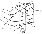
本発明者らは、タービンブレードが失速するメカニズムを解明するために、従来の波力発電タービンについて空気流の流れ場の解析を行った。その結果を図4〜6に基づいて説明する。 The present inventors analyzed the flow field of the air flow of the conventional wave power generation turbine in order to elucidate the mechanism by which the turbine blade stalls. The results will be described based on FIGS.
図4は、従来の波力発電タービンにおけるタービンブレードまわりの空気流の流れを、図6は、従来の波力発電タービンまわり空気流の流れを、それぞれ解析した結果をそれぞれ示しており、図5は、図4のB矢視図である。 FIG. 4 shows the flow of air flow around the turbine blades in the conventional wave power generation turbine, and FIG. 6 shows the results of analysis of the flow of air flow around the conventional wave power generation turbine, respectively. Is a view on arrow B in FIG.
図4〜図6から明らかなように、円筒風洞1(図1参照)の内壁と、ブレード先端11との間隙を通過した翼端漏れ流れ12により、ブレード先端11の下流側で翼端漏れ渦13が形成されている。一方、タービンブレード4の前方を通過した空気流は、翼端漏れ渦13により、タービンブレード4の下流側表面から剥離して、前端失速流れ15が形成されている。
As is apparent from FIGS. 4 to 6, the tip leakage vortex downstream of the
この解析結果から、翼端漏れ渦13は、タービンブレード4の失速を助長することがわかった。すなわち、翼端漏れ渦13を低減することによって、タービンブレード4の失速を防止することができる。
From this analysis result, it was found that the
翼漏れ渦13を低減するためには、円筒空洞の内壁と、ブレード先端11との間隙を狭くすることが考えられる。しかしながら、波力発電タービンの構造上、円筒空洞1の内壁と、ブレード先端11との間には一定の間隙を設けることが必要であって、この方法では、所望の効果は期待できない。
In order to reduce the
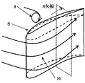
本発明は、円筒空洞の内壁と、ブレード先端11との間に一定の間隙を設けつつ、翼漏れ渦13を低減するものであり、本発明に係る波力発電タービンの一実施例を図2、図3を参照しつつ説明する。
The present invention reduces
図2、図3に示すように、本発明による波力発電タービンは、長さLのタービンブレード4が、ブレード根元から0.86Lの箇所を境にして、ブレード先端8まで、滑らかな曲面状に形成された先細り形状となっている。円筒空洞1(図1参照)の内壁の近傍を流れてきた空気流は、ブレード先端8が先細り形状となっているため、ブレード先端8の上流側でコーナー渦9が形成される。ブレード先端8の上流側で形成されたコーナー渦9により、円筒空洞1の内壁と、ブレード先端11との間隙を通過する翼端漏れ流れ12が大幅に減少する。翼端漏れ流れ12の減少に伴い翼端漏れ渦13も減少するため、タービンブレード4の下流側表面から空気流の剥離が抑制され、タービンブレード4の失速範囲を減少させることができる。
As shown in FIGS. 2 and 3, in the wave power generation turbine according to the present invention, the
本実施の形態では、ブレード先端8が、曲面状に形成されているが、このような形状に限定されるものではない。すなわち、ブレード先端8の上流側でコーナー渦9が形成される形状であればよいのであって、必ずしも曲面状に形成する必要はない。例えば、ブレード先端8を、直線状の先細り形状や、複数の段差を設け段階的に先細り形状としてもよい。
In the present embodiment, the
本発明は、波力発電装置に用いられる波力発電タービンに利用することができる。 The present invention can be used for a wave power generation turbine used for a wave power generation device.
1 円筒風洞
2 ロータハブ
3 回転軸
4 対称翼型タービンブレード
5 発電機
6 空気流(往復流)
7 回転方向
8 ブレード先端
9 ブレード先端漏れ渦流
10 ブレード前端失速流れ
11 ブレード先端
12 翼端漏れ流れ
13 翼端漏れ渦
14 ブレード前縁失速
15 前縁失速流れ
1
7 Direction of
Claims (1)
前記回転軸に固着され、半径方向に向かって延在する複数のタービンブレードを有するロータハブとを備え、空気流の流れ方向にかかわらず同一方向に回転するように構成された波力発電タービンであって、
前記タービンブレードは、その全長Lに対して、ブレード根元から長さ0.75L以上の領域におけるある箇所を境にして、厚さが半径方向に向かって漸次先細り状に形成されたことを特徴とする波力発電タービン。 A rotary shaft disposed in a cylindrical wind tunnel and rotatably supported concentrically with the cylindrical wind tunnel;
And a rotor hub having a plurality of radially extending turbine blades fixed to the rotating shaft and configured to rotate in the same direction regardless of the flow direction of the air flow. ,
The turbine blades, and characterized with respect to its entire length L, and the boundary of a certain point in the length 0.75L or more regions from the blade root, that the thickness is formed on the gradually tapered toward the radially Wave power generation turbine.
Priority Applications (1)
| Application Number | Priority Date | Filing Date | Title |
|---|---|---|---|
| JP2014084567A JP6524397B2 (en) | 2014-04-16 | 2014-04-16 | Wave power generation turbine |
Applications Claiming Priority (1)
| Application Number | Priority Date | Filing Date | Title |
|---|---|---|---|
| JP2014084567A JP6524397B2 (en) | 2014-04-16 | 2014-04-16 | Wave power generation turbine |
Publications (2)
| Publication Number | Publication Date |
|---|---|
| JP2015203396A JP2015203396A (en) | 2015-11-16 |
| JP6524397B2 true JP6524397B2 (en) | 2019-06-05 |
Family
ID=54596991
Family Applications (1)
| Application Number | Title | Priority Date | Filing Date |
|---|---|---|---|
| JP2014084567A Active JP6524397B2 (en) | 2014-04-16 | 2014-04-16 | Wave power generation turbine |
Country Status (1)
| Country | Link |
|---|---|
| JP (1) | JP6524397B2 (en) |
Family Cites Families (5)
| Publication number | Priority date | Publication date | Assignee | Title |
|---|---|---|---|---|
| JPS5783670A (en) * | 1980-11-14 | 1982-05-25 | Mitsubishi Heavy Ind Ltd | Biaxial type water mill and wind mill |
| CH659851A5 (en) * | 1981-06-05 | 1987-02-27 | Escher Wyss Ag | TURBINE. |
| GB2440344A (en) * | 2006-07-26 | 2008-01-30 | Christopher Freeman | Impulse turbine design |
| JP4939252B2 (en) * | 2007-02-14 | 2012-05-23 | 株式会社ベルシオン | Wind hydraulic generator |
| JP2013256920A (en) * | 2012-06-14 | 2013-12-26 | Japan Aerospace Exploration Agency | Wave-power generation device |
-
2014
- 2014-04-16 JP JP2014084567A patent/JP6524397B2/en active Active
Also Published As
| Publication number | Publication date |
|---|---|
| JP2015203396A (en) | 2015-11-16 |
Similar Documents
| Publication | Publication Date | Title |
|---|---|---|
| JP5090023B2 (en) | Eddy current generating cyclic propeller | |
| CN102884311B (en) | Flow Control for Vertical Axis Wind Turbines (VAWT) | |
| CN106414999A (en) | Noise reduction means for a rotor blade of a wind turbine | |
| US10690112B2 (en) | Fluid turbine rotor blade with winglet design | |
| CN108150348B (en) | A kind of blade of vertical axis wind turbine component and its synthesizing jet-flow control method | |
| JP2011503407A (en) | Wind turbine with two consecutive propellers | |
| AU2012238440A1 (en) | Diffuser augmented wind turbines | |
| US10280895B1 (en) | Fluid turbine semi-annular delta-airfoil and associated rotor blade dual-winglet design | |
| CN107514290A (en) | A kind of asymmetric air turbine suitable for Asia sea area oscillaton water column type Wave energy electric generator | |
| CN104847582B (en) | Vertical wind power generator | |
| JP5832068B2 (en) | Wind power generator | |
| WO2014006542A2 (en) | Turbine arrangement | |
| US10202961B2 (en) | Fluid turbine semi-shroud and associated rotor blade dual-winglet design | |
| WO2014048468A9 (en) | Turbine with a nozzle body | |
| US20130022477A1 (en) | Turbines with integrated compressors and power generators | |
| JP6524396B2 (en) | Wave power generation turbine | |
| JP6524397B2 (en) | Wave power generation turbine | |
| JP6357668B2 (en) | Wave power turbine | |
| EP3098436B1 (en) | Noise reducing flap with opening | |
| JP6354051B2 (en) | Wave power turbine | |
| GB2530048A (en) | A self-rectifying turbine | |
| EP2194266A1 (en) | Rotor-stator arrangement of a wind energy converter | |
| CN207406382U (en) | A kind of asymmetric air turbine suitable for Asia sea area oscillaton water column type Wave energy electric generator | |
| KR20130008181A (en) | Wind power genelator | |
| JP2020033885A (en) | Axial flow impeller and turbine |
Legal Events
| Date | Code | Title | Description |
|---|---|---|---|
| A621 | Written request for application examination |
Free format text: JAPANESE INTERMEDIATE CODE: A621 Effective date: 20161220 |
|
| A521 | Request for written amendment filed |
Free format text: JAPANESE INTERMEDIATE CODE: A821 Effective date: 20161220 |
|
| A977 | Report on retrieval |
Free format text: JAPANESE INTERMEDIATE CODE: A971007 Effective date: 20170927 |
|
| A131 | Notification of reasons for refusal |
Free format text: JAPANESE INTERMEDIATE CODE: A131 Effective date: 20171010 |
|
| A02 | Decision of refusal |
Free format text: JAPANESE INTERMEDIATE CODE: A02 Effective date: 20171226 |
|
| A521 | Request for written amendment filed |
Free format text: JAPANESE INTERMEDIATE CODE: A523 Effective date: 20180323 |
|
| A911 | Transfer to examiner for re-examination before appeal (zenchi) |
Free format text: JAPANESE INTERMEDIATE CODE: A911 Effective date: 20180502 |
|
| A912 | Re-examination (zenchi) completed and case transferred to appeal board |
Free format text: JAPANESE INTERMEDIATE CODE: A912 Effective date: 20180601 |
|
| A521 | Request for written amendment filed |
Free format text: JAPANESE INTERMEDIATE CODE: A523 Effective date: 20181226 |
|
| A61 | First payment of annual fees (during grant procedure) |
Free format text: JAPANESE INTERMEDIATE CODE: A61 Effective date: 20190319 |
|
| R150 | Certificate of patent or registration of utility model |
Ref document number: 6524397 Country of ref document: JP Free format text: JAPANESE INTERMEDIATE CODE: R150 |
|
| R250 | Receipt of annual fees |
Free format text: JAPANESE INTERMEDIATE CODE: R250 |
|
| R250 | Receipt of annual fees |
Free format text: JAPANESE INTERMEDIATE CODE: R250 |
|
| R250 | Receipt of annual fees |
Free format text: JAPANESE INTERMEDIATE CODE: R250 |
|
| R250 | Receipt of annual fees |
Free format text: JAPANESE INTERMEDIATE CODE: R250 |