JP5832068B2 - Wind power generator - Google Patents
Wind power generator Download PDFInfo
- Publication number
- JP5832068B2 JP5832068B2 JP2009169475A JP2009169475A JP5832068B2 JP 5832068 B2 JP5832068 B2 JP 5832068B2 JP 2009169475 A JP2009169475 A JP 2009169475A JP 2009169475 A JP2009169475 A JP 2009169475A JP 5832068 B2 JP5832068 B2 JP 5832068B2
- Authority
- JP
- Japan
- Prior art keywords
- airflow
- guide plate
- wind power
- horizontal
- power generator
- Prior art date
- Legal status (The legal status is an assumption and is not a legal conclusion. Google has not performed a legal analysis and makes no representation as to the accuracy of the status listed.)
- Active
Links
Images


Classifications
-
- Y—GENERAL TAGGING OF NEW TECHNOLOGICAL DEVELOPMENTS; GENERAL TAGGING OF CROSS-SECTIONAL TECHNOLOGIES SPANNING OVER SEVERAL SECTIONS OF THE IPC; TECHNICAL SUBJECTS COVERED BY FORMER USPC CROSS-REFERENCE ART COLLECTIONS [XRACs] AND DIGESTS
- Y02—TECHNOLOGIES OR APPLICATIONS FOR MITIGATION OR ADAPTATION AGAINST CLIMATE CHANGE
- Y02E—REDUCTION OF GREENHOUSE GAS [GHG] EMISSIONS, RELATED TO ENERGY GENERATION, TRANSMISSION OR DISTRIBUTION
- Y02E10/00—Energy generation through renewable energy sources
- Y02E10/70—Wind energy
- Y02E10/74—Wind turbines with rotation axis perpendicular to the wind direction
Description
本発明は、全方位からの気流に対応した風力発電装置の原理、構造に関する。 The present invention relates to the principle and structure of a wind turbine generator that supports airflow from all directions.
従来の風力発電機は気流の強さを利用して、その気流の向きに回転翼を対向させて、その主軸を回転させ発電させて、機械エネルギーを電気エネルギーに変えるものが一般的である。 Conventional wind power generators generally use the strength of the airflow to make the rotor blades face each other in the direction of the airflow, rotate the main shaft to generate power, and convert mechanical energy into electrical energy.
本発明は、上記の欠点をなくす為に、風力発電装置を固定したまま、自然の大気中の気流に対して、単方位、双方位又は全方位に対応できるものであり、効率的に発電を行える装置を提供するものである。 In order to eliminate the above disadvantages, the present invention can deal with unidirectional, bilateral or omnidirectional airflow in the natural atmosphere with the wind power generator fixed, and can efficiently generate power. An apparatus capable of performing the above is provided.
つまり、気流の方向に左右される事なく、微風にも気流増速器を利用して、風力を増し、発電する風力発電装置である。 In other words, it is a wind power generator that generates power by increasing the wind force by using an air flow speed-up gear even for light winds regardless of the direction of the air flow.
上記目的を達成する為に、本発明に係る風力発電装置は、気流を生じている大気中に、水平誘導板、垂直誘導板又は、それらを組み合わせた気流増速器を配設し、その回転翼の回転軸に風力発電機を取り付けて発電させるものである。 In order to achieve the above object, the wind turbine generator according to the present invention is provided with a horizontal induction plate, a vertical induction plate, or an airflow speed-intensifier combining them in the atmosphere generating an airflow, and the rotation thereof. A wind power generator is attached to the rotating shaft of the wing to generate electricity.
つまり、その回転翼部と、前記各回転軸の一端部に接続された風力発電機と、前記回転翼の羽根部に気流を誘導する気流誘導板を用いた気流増速器で構成されたものである。 That is, it is composed of an airflow speed increaser using the rotor blade part, a wind power generator connected to one end part of each rotating shaft, and an airflow guide plate for guiding an airflow to the blade part of the rotor blade. It is.
即ち、本発明は、大気中の回転翼部の羽根部に気流を誘導するようにし、その背面側は、対向気流による空気抵抗が少ない流線形又は鋭角状にしているものである。気流誘導、圧縮式の気流増速器を採用し、気流の流速を増大させ、この流速を高めた気流で、風力発電機につながる回転翼を駆動するのであり、回転軸の法線方向の単方位、双方位又は全方位からの気流に対応できるものである。 That is, according to the present invention, the airflow is guided to the blade portion of the rotary blade portion in the atmosphere, and the back side thereof has a streamlined shape or an acute angle shape with less air resistance due to the opposed airflow. Adopting an airflow induction and compression airflow speed increaser, the flow velocity of the airflow is increased, and the rotor blade connected to the wind power generator is driven by the airflow with the increased airflow velocity. It can deal with airflow from azimuth, bilateral or omnidirectional.
上記目的を達成する為に、本発明は、無尽蔵にある自然エネルギーを利用して発電するもので、気流を増速し、回転翼部の羽根部に加えて、その高エネルギーを電気エネルギーに変えるものである。 In order to achieve the above object, the present invention generates power using inexhaustible natural energy, accelerates the airflow, and converts the high energy into electrical energy in addition to the blades of the rotor blades. Is.
請求項1に記載の発明は、上下に所定間隔を保って互いに対向して配置され、中心部が開口したドーナッツ板状を呈する一対の水平誘導板と、該水平誘導板間の開口部に回転軸が配置されて同回転軸に羽根部が取付けられた回転翼部と、該回転翼部の外周側の前記水平誘導板の間に前記回転軸の軸芯から偏芯させて放射状に複数配置した垂直誘導板と、から構成され、前記羽根部の回転移動方向側は鋭角及び/又は流線型とし、該回転移動方向と反対側に気流を取り込む気流取り込み口を有する奥行きのある空洞を具備する一方、前記水平誘導板は、気流進入側の幅を広角且つその幅員を大きくし、該幅員が回転翼部方向に徐々に小さくなっているとともに、該水平誘導板と、該水平誘導板間に組み入れた前記垂直誘導板とによって気流増速器が形成され、該気流増速器によって増速された気流の誘導先が、前記羽根部の気流取り込み口に向けられており、かつ、前記回転翼部は、前記水平誘導板の開口部に着脱自在に取り付けられているとともに、この水平誘導板の開口部は、前記回転翼部の軸受板でカバーされ、さらにこの軸受板又は前記水平誘導板に、開閉を制御出来る排気口が設けられていることを特徴とする風力発電装置である。
The invention according to
請求項2に記載の発明は、請求項1に記載の風力発電装置において、上記水平誘導板の間に気流の出入り口を形成する双方向性垂直誘導壁が配置されていることを特徴とする風力発電装置である。
According to a second aspect of the invention, the wind power generator according to
請求項3に記載の発明は、請求項1又は2に記載の風力発電装置において、気流増速部と上記回転翼部が単独又は多段形成されていることを特徴とする風力発電装置である。 The invention according to claim 3 is the wind power generator according to claim 1 or 2 , wherein the airflow speed increasing portion and the rotor blade portion are formed individually or in multiple stages.
上記の発明は、回転翼部の回転軸を垂直に設置した場合、水平方向の全方位からの微風にも対応できる風力発電装置である。 Said invention is a wind power generator which can respond also to the breeze from all directions of a horizontal direction, when the rotating shaft of a rotary blade part is installed vertically.
つまり、全方位からの気流を気流増速器により、増速させた気流を取り込み、回転翼羽根部の気流取り込み口を加圧して、発電機に繋がる回転翼の回転軸を駆動させることができる非常に効率的な発電を行う事ができる風力発電装置である。 That is, it is possible to drive the rotating shaft of the rotor blade connected to the generator by capturing the airflow from the omnidirectional direction by using the airflow accelerator to pressurize the airflow intake port of the rotor blade blade portion. It is a wind power generator that can perform very efficient power generation.
以下に本発明の実施形態の一例を図面に基づいて説明する。 Hereinafter, an example of an embodiment of the present invention will be described with reference to the drawings.
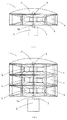
図1に示すように、本実施形態の風力発電装置1は全方位からの気流を利用して発電を行う風力発電装置であって、回転翼部(4、5、6又は7)、回転軸3及び複数の気流増速器8を組み合わせた気流増速部8Uと発電機2とから主に構成される。 As shown in FIG. 1, the
(a)は気流増速部8U及び回転翼部4の設置を1段のものであり、(b)は気流増速部8U及び回転翼部4を3段にしたものであるが、用途に応じて、回転翼部5,6又は7を採用出来るものとし、又、それ以外の回転翼を設置しても良い。上記気流増速部8U及び該回転翼部(4,5,6又は7)の設置を幾段にするかは、必要な供給電力に応じて決めれば良い。(A) is a one-stage installation of the airflow speed increasing part 8U and the
このように回転翼部4が取り付けられた上記回転軸3の一端部には、発電機2が接続されている。気流増速器8は、気流が緩やかな場所でも、加圧して、羽根部(4a〜f)に送風出来る為に非常に役立つものである。 The
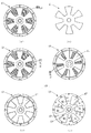
図2において、各羽根部(4a〜f)は、回転軸3に固定されており、回転翼部(4、5,6,7)は少なくとも3個以上の回転翼を有するものとする。 In FIG. 2, each blade | wing part (4a-f) is being fixed to the rotating shaft 3, and a rotating blade part (4,5,6,7) shall have at least 3 or more rotating blades.
又、図2の(a)、(b)、(c)、(d)は、前記の風力発電装置1に採用できる4種類の回転翼部(4,5,6,7)を示すものである。これら全ての羽根部(4a〜f、5a〜f、6a〜f、7a〜f)は気流を取り込む為の空洞を有し、その羽根部の点線は、その奥行きを示している。又、回転翼部(4、5、6、7)において、その羽根部(4a〜f、5a〜f、6a〜f、7a〜f)の気流取り込み口(斜線で示している部分)の背面は、流線形又は鋭角にして、回転時の対向気圧による空気抵抗を少なくしている。 2 (a), (b), (c), and (d) show four types of rotor blades (4, 5, 6, and 7) that can be employed in the
又、羽根部で受ける風圧が非常に高い場合は、その風圧を調整する為、気流取り込み口の背面に排気口を設けて、気圧又はプログラム制御により、自動的にその排気口を制御し、発電機2の回転軸2の回転数を制御して、強い風力に対応しても良い。 Also, if the wind pressure received by the blades is very high, an exhaust port is provided on the back of the airflow intake port to adjust the wind pressure, and the exhaust port is automatically controlled by atmospheric pressure or program control to generate power. The rotational speed of the rotating
図3は、気流を回転翼方向に誘導する水平誘導板20a、bを示す図である。図(a)は、該水平誘導板20a、bの斜視図である。図(b)は該水平誘導板20a、bを横から視た図である。図に示すように、二枚の水平誘導板20a、bを対とし、円形状のもので、その中心付近は水平状で、その側面方向に傾斜を持たせ広角にし、全方向(360度)方向に対応出来るようにしている。 FIG. 3 is a diagram showing
図4は、垂直誘導板30(a〜l)を示す斜視図である。これは水平方向の気流の向きを誘導するもので、全ての誘導板は気流を回転翼の羽根部に誘導されるように配置されているものであり、垂直誘導板30(a〜l)を12枚用いて回転軸の軸芯から偏芯させて、放射状に配置し、全方位(360度)からの気流に対応出来るものである。 FIG. 4 is a perspective view showing the vertical guide plates 30 (a to l). This guides the direction of the airflow in the horizontal direction, and all the guide plates are arranged so that the airflow is guided to the blades of the rotor blades, and the vertical guide plates 30 (a to l) are installed. Using 12 sheets, they are eccentric from the axis of the rotating shaft and are arranged in a radial manner so that they can handle airflow from all directions (360 degrees).
図5は上記の水平誘導板20a、bと垂直誘導板30(a〜l)を組み合わせた気流増速部8Uを横から視た図である。図からも解るように、気流受口側は開口面積を大きくし、回転翼部の羽根部方向へ向って徐々に開口面積を小さくし、気流を増速したもので、全方位、360度方位からの気流に対応している。 FIG. 5 is a side view of the air flow speed increasing portion 8U in which the
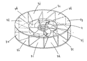
図6は、上記の気流増速器8及び気流増速部8Uの斜視図である。(a)は該気流増速器8の単独のものであり、(b)は気流増速器8を放射状に12個配設した全方位(360度)に対応できる。 FIG. 6 is a perspective view of the airflow
又、図(a)、(b)に示すように、該気流増速器8は、その開口面積を下流に向って徐々に減少させている構造であり、且つ、その誘導先が回転翼部(4)、(5)、(6)、(7)の羽根部の気流受口である為、回転翼部の羽根部に高い気圧が加わるようにしている。つまり、気流増速器8内を圧力管状態とし、気流速度を増加させているものである。 Further, as shown in FIGS. 4A and 4B, the air flow speed increaser 8 has a structure in which the opening area is gradually decreased toward the downstream side, and the guide destination is the rotor blade portion. (4), (5), (6), and (7), because the airflow receiving port of the blade portion, high air pressure is applied to the blade portion of the rotary blade portion. That is, the
図7は上記気流増速部8U(360度対応)と回転翼部4を組み合わせた回転翼部4部分の透視、斜視図である。 FIG. 7 is a perspective view of the airfoil speed increasing portion 8U (corresponding to 360 degrees) and the
図8は該回転翼部4と気流の関係を示したものである。(a)は従来型の回転翼部4と気流との対応関係を示した図であり、(b)は回転軸の軸芯から偏芯させて放射状に12枚の垂直誘導板30(a〜l)で(360度対応)を配設し、該回転翼部4と気流の関係を上部から視た図である。 FIG. 8 shows the relationship between the
又、流速の速い気流を受ける場合、回転翼部の羽根部は空洞を有する回転翼(4a〜f)を設けているので、圧力の高い気流を一時的に空洞(点線は奥行きを示す)にて蓄積し、その気流の圧力により、回転力を増し、回転軸3を効率よく回転させるものである。又、(b)図に示すように回転翼(4d、4e、4f)側は、気流の圧力を直接受けない構造となっており、且つ、回転翼部の羽根部の背面側が鋭角又は流線形になっている事により、更に対向気圧による空気抵抗を低減している。 In addition, when receiving an air flow with a high flow velocity, the blade portion of the rotor blade portion is provided with a rotor blade (4a to f) having a cavity, so that a high-pressure air current is temporarily turned into a cavity (the dotted line indicates the depth) The rotational force is increased by the pressure of the airflow, and the rotating shaft 3 is efficiently rotated. Further, as shown in FIG. 5B, the rotor blades (4d, 4e, 4f) side is structured not to receive the airflow pressure directly, and the back side of the blades of the rotor blades is acute or streamlined. Therefore, the air resistance due to the counter pressure is further reduced.
図9は気流と前記水平誘導板20a,b及び回転翼部4との関係を横方向から視た図である、(a)は、該水平誘導板20a、bがない場合の回転翼4と気流方向を示したものであり、(b)は気流と該水平誘導板20a、bを設置した場合の回転翼部4と気流との関係を示したものである。 FIG. 9 is a view of the relationship between the airflow, the
上記図8の(b)に示す12枚の垂直誘導板(30a〜l)と図9の(b)の水平誘導板(20a〜b)の効果を持ち合わせたものが気流増速器である。 A combination of the effects of the twelve vertical guide plates (30a-l) shown in FIG. 8 (b) and the horizontal guide plates (20a-b) shown in FIG.
図10は、上記回転翼部4を取り囲むように回転軸の軸芯から偏芯させて、放射状に配設された12枚の垂直誘導板30(a〜l)と気流との関係を上部から視た図である。これは、図に示す様に気流が進入する側、排気口側の区別はなく共用している。前記回転軸3の法線方向からの気流に対して、全方位(360度方向)に対応できる構造となっている。 FIG. 10 shows the relationship between the twelve vertical guide plates 30 (a to l) radially arranged from the axis of the rotary shaft so as to surround the
以下に本発明の実施形態の二例を図面に基づいて説明する。 Hereinafter, two examples of embodiments of the present invention will be described with reference to the drawings.
図11は、気流双方向性対応の回転翼部4と垂直誘導板(41a〜f)及び誘導壁(40a、b)に対する気流との関係を上部から視た図である。図に示す様に気流が進入する側、排気口側の区別はなく併用しており、気流誘導壁(40a、b)によって、回転翼部の羽根部気流受口の背面側が回転して戻って来る場合でも、該背面側に気流は誘導されない構造となっている。但し、この図は垂直方向の気流は想定しておりません。上記垂直誘導板41(a〜f)及び40(a、b)に替えて、前記気流増速器8を配設した場合は上述の通りとなる。 FIG. 11 is a view of the relationship between the airflow bidirectional airflow-compatible
以下に本発明の実施形態の三例を図面に基づいて説明する。 Hereinafter, three examples of embodiments of the present invention will be described with reference to the drawings.
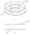
図12は、二枚を対とした円形状の中心部を円状に切り抜いたドーナッツ板状の水平誘導板200a,bの図である。(a)は、その斜視図である。(b)該水平誘導板を横から視た図である。図に示すように、実施形態一例のように、気流進入側の二枚の誘導板の幅員を変えているものではない。 FIG. 12 is a diagram of a donut-plate-shaped horizontal guide plate 200a, b obtained by cutting out a circular center part of a pair of two in a circular shape. (A) is the perspective view. (B) It is the figure which looked at this horizontal guide plate from the side. As shown in the figure, the widths of the two guide plates on the air flow entrance side are not changed as in the example of the embodiment.
図13は、垂直誘導板300(a〜l)を示す斜視図である。個々の該垂直誘導板300(a〜l)は、長方形のもので、該垂直誘導板を回転軸の軸芯から偏芯させて放射状に配置し、その中心部に回転翼部を配置するものである。 FIG. 13 is a perspective view showing the vertical guide plates 300 (a to l). Each of the vertical guide plates 300 (a to l) is rectangular, and the vertical guide plates are eccentrically arranged from the axis of the rotation shaft and are arranged radially, and the rotary blades are arranged at the center thereof. It is.
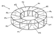
図14は上記、図13及び14に示す水平誘導板及び垂直誘導板を組み合わせた気流増速部80Uの斜視図である。図からも解るように、全方位360度の方向からの気流に対応できる構造となっている。FIG. 14 is a perspective view of an airflow speed increasing portion 80U in which the horizontal guide plate and the vertical guide plate shown in FIGS. 13 and 14 are combined. As can be seen from the figure, it has a structure that can handle airflow from 360 degrees in all directions.
図15は、上記、気流増速部81の中心部を、円形状である回転翼部の軸受板50にてカバーを行い固定している気流増速部81Uの斜視図である。この気流増速部81Uは回転軸の軸芯から偏芯させて放射状に気流増幅器80を12個配設したもので、全方位(360度)からの気流に対応できるようにしている。 FIG. 15 is a perspective view of the airflow acceleration portion 81U in which the central portion of the airflow acceleration portion 81 is covered and fixed by a bearing
図16に示す気流増速部82Uは、図15のドーナッツ状の平面板を用いた気流増速部81Uの、該回転翼部の軸受板に、制御出来る排気口を設けているものである。その排気口の開閉度を風力の強さにより自動制御するものである。 An airflow speed increasing portion 82U shown in FIG. 16 is provided with a controllable exhaust port on the bearing plate of the rotor blade portion of the airflow speed increasing portion 81U using the donut-shaped flat plate of FIG. The opening / closing degree of the exhaust port is automatically controlled by the strength of the wind force.
又、放射状に配置した気流増速部の中央部に設置した回転翼部4の羽根部4(a〜f)に風圧を加えて、該回転翼部4を駆動し、その回転軸3を回転させ、該回転翼に加わる気圧を排気制御により出来る限り、回転を安定するようにしたものである。 In addition, wind pressure is applied to the blades 4 (af) of the
図17は上記の排気口開閉を制御する軸受板60の図面である。(a)は軸受板のカバーに制御用の排気口開閉板を取り付けていない状態の図である。(b)は該軸受板のカバーに取り付ける該排気用開閉板61の図である。(c)は該排気口開閉板61を全開した図である。(d)は半開の図面である。(e)は全閉の図である。(f)は排気口の開閉にヒンジ63を用いているものである。 FIG. 17 is a drawing of the bearing
これらは気圧によってその開閉度を自動制御するものである。その開閉は回転軸3の回転する力を利用しても良いし、別に開閉用モーターにより行なっても良い。当然の事ながら、手動で行なう事も出来るものとする。 These automatically control the degree of opening and closing by the atmospheric pressure. The opening / closing may be performed by using the rotating force of the rotating shaft 3 or may be performed by a separate opening / closing motor. Of course, it can also be done manually.
又、上記の排気制御機能の設置は上記回転軸受板の代わりに、上記気流増速器の水平誘導板部分に設ける事もできるものとする。 In addition, the exhaust control function can be installed in the horizontal guide plate portion of the airflow speed increaser instead of the rotary bearing plate.
図18の(a)は上記気流増速部80Uと回転翼4の関係を示す図であり、(b)は気流増速部82U及び該回転翼の軸受板60に設けている制御可能の排気口と回転翼の関係を示すもので排気口全閉の図である。FIG. 18A is a view showing the relationship between the airflow speed increasing portion 80U and the
1、風力発電装置
2、発電機
3、回転軸
4、5、6、7 回転翼部
4a〜f、5a〜f、6a〜f、7a〜f 羽根部
8、気流増速器
8U、気流増速部
9、9a 軸受
20a、20b、 水平誘導板
30(a〜l) 垂直誘導板
40a、40b 双方向性垂直誘導壁
41a〜f 双方向性水平誘導板
50、第三実施形態の回転軸受板
60、第三実施形態の排気口を設けた回転軸受板
61、第三実施形態の排気口開閉板
62、第三実施形態のヒンジを用いた排気口開閉板
63、第三実施形態の排気口開閉板のヒンジ
80、気流増速器
80U、気流増速部
200(a、b)、第三実施形態の水平誘導板
300(a〜l)、第三実施形態の垂直誘導板
81U、第三実施形態の回転軸受板を設けた気流増速部
82U、第三実施形態の回転軸受板に排気口を設けた気流増速部DESCRIPTION OF
Claims (3)
前記羽根部の回転移動方向側は鋭角及び/又は流線型とし、該回転移動方向と反対側に気流を取り込む気流取り込み口を有する奥行きのある空洞を具備する一方、
前記水平誘導板は、気流進入側の幅を広角且つその幅員を大きくし、該幅員が回転翼部方向に徐々に小さくなっているとともに、該水平誘導板と、該水平誘導板間に組み入れた前記垂直誘導板とによって気流増速器が形成され、該気流増速器によって増速された気流の誘導先が、前記羽根部の気流取り込み口に向けられており、
かつ、前記回転翼部は、前記水平誘導板の開口部に着脱自在に取り付けられているとともに、この水平誘導板の開口部は、前記回転翼部の軸受板でカバーされ、さらにこの軸受板又は前記水平誘導板に、開閉を制御出来る排気口が設けられていることを特徴とする風力発電装置。 Vertically disposed opposite each other with a predetermined interval, a pair of horizontal guide plate exhibiting a donut-shaped center portion is open, is the rotation axis is disposed in an opening of the horizontal induction plates in the rotation axis a rotary blade portion blade portion is attached, is composed of a vertical guide plate in which a plurality radially arranged by eccentric to the horizontal induction plates on the outer peripheral side from the axis of the rotary shaft of said rotary blade section,
While the rotational movement direction side of the blade part has an acute angle and / or streamline type, and has a deep cavity having an airflow intake port for taking in an airflow on the opposite side to the rotational movement direction,
The horizontal guide plate has a wide angle on the air flow entrance side and a wider width, and the width is gradually reduced in the direction of the rotor blade, and is incorporated between the horizontal guide plate and the horizontal guide plate. An airflow speed increaser is formed by the vertical guide plate, and the airflow induction destination accelerated by the airflow speed increaser is directed to the airflow intake port of the blade part,
The rotary blade is detachably attached to the opening of the horizontal guide plate, and the opening of the horizontal guide plate is covered with a bearing plate of the rotary blade, and the bearing plate or The wind power generator characterized by the said horizontal induction board being provided with the exhaust port which can control opening and closing .
Priority Applications (1)
| Application Number | Priority Date | Filing Date | Title |
|---|---|---|---|
| JP2009169475A JP5832068B2 (en) | 2009-06-29 | 2009-06-29 | Wind power generator |
Applications Claiming Priority (1)
| Application Number | Priority Date | Filing Date | Title |
|---|---|---|---|
| JP2009169475A JP5832068B2 (en) | 2009-06-29 | 2009-06-29 | Wind power generator |
Related Child Applications (1)
| Application Number | Title | Priority Date | Filing Date |
|---|---|---|---|
| JP2015132808A Division JP6054480B2 (en) | 2015-07-01 | 2015-07-01 | Wind power generator |
Publications (3)
| Publication Number | Publication Date |
|---|---|
| JP2011007169A JP2011007169A (en) | 2011-01-13 |
| JP2011007169A5 JP2011007169A5 (en) | 2012-09-06 |
| JP5832068B2 true JP5832068B2 (en) | 2015-12-16 |
Family
ID=43564096
Family Applications (1)
| Application Number | Title | Priority Date | Filing Date |
|---|---|---|---|
| JP2009169475A Active JP5832068B2 (en) | 2009-06-29 | 2009-06-29 | Wind power generator |
Country Status (1)
| Country | Link |
|---|---|
| JP (1) | JP5832068B2 (en) |
Families Citing this family (5)
| Publication number | Priority date | Publication date | Assignee | Title |
|---|---|---|---|---|
| KR101306754B1 (en) * | 2011-02-01 | 2013-09-13 | 고영은 | Wind power generator with wind guide |
| JP5637388B2 (en) * | 2011-02-28 | 2014-12-10 | 豊田合成株式会社 | In-vehicle wind power generator |
| JP6037059B1 (en) * | 2015-04-30 | 2016-11-30 | 正治 内田 | Fluid power generator |
| WO2016174799A1 (en) * | 2015-04-30 | 2016-11-03 | 正治 内田 | Fluid power-generation device |
| CN113044988B (en) * | 2021-03-12 | 2022-11-18 | 重庆市水产技术推广总站 | Multistage constructed wetland breeding tail water treatment system |
Family Cites Families (5)
| Publication number | Priority date | Publication date | Assignee | Title |
|---|---|---|---|---|
| FR530634A (en) * | 1919-06-14 | 1921-12-27 | Air turbine | |
| DE2923658A1 (en) * | 1979-06-11 | 1980-12-18 | Lvu Gmbh | Wind power turbine with vertical axis - is connected to medium site generator for providing power for single houses |
| JPS5815767A (en) * | 1981-07-20 | 1983-01-29 | Haruo Fukuda | Wind-powered pumping-up power plant |
| JP2005054695A (en) * | 2003-08-05 | 2005-03-03 | Tomotake Shigemori | Wind power generating device |
| JP2007064207A (en) * | 2005-07-31 | 2007-03-15 | Hikoshichi Takahashi | Wind power generator |
-
2009
- 2009-06-29 JP JP2009169475A patent/JP5832068B2/en active Active
Also Published As
| Publication number | Publication date |
|---|---|
| JP2011007169A (en) | 2011-01-13 |
Similar Documents
| Publication | Publication Date | Title |
|---|---|---|
| US6655907B2 (en) | Fluid driven vacuum enhanced generator | |
| US7550865B2 (en) | Wind turbine having variable pitch airfoils that close when moving against the direction of the wind | |
| JP5832068B2 (en) | Wind power generator | |
| US8998562B2 (en) | Hollow rotor core for generating a vortex in a wind turbine | |
| JP2014513233A (en) | Wind turbine enhanced by diffuser | |
| KR20140040714A (en) | Diffuser augmented wind turbines | |
| WO2006123951A1 (en) | A wind turbine | |
| JP6054480B2 (en) | Wind power generator | |
| JP5606699B2 (en) | Underwater power generator | |
| CN112912613A (en) | Wind turbine | |
| US9441608B2 (en) | Wind turbine | |
| CN210290004U (en) | Wind turbine, compressor and generator | |
| KR101732145B1 (en) | wind power generation apparatus | |
| JP5826889B2 (en) | Underwater power generator | |
| US8039985B2 (en) | Wind turbine | |
| JP2004285968A (en) | Wind mill | |
| JP4611586B2 (en) | Energy conversion system and related methods | |
| JP6354051B2 (en) | Wave power turbine | |
| JP6524396B2 (en) | Wave power generation turbine | |
| JP6144807B1 (en) | Windmill | |
| JP6524397B2 (en) | Wave power generation turbine | |
| JP2003120501A (en) | Cross flow windmill and wind power generation device | |
| KR101009591B1 (en) | Windmill for wind power generator | |
| RU2204051C2 (en) | Wind-power plant | |
| JP2004011599A (en) | Wind flow passage forming method in cross flow wind mill, cross flow wind mill, and wind power generator |
Legal Events
| Date | Code | Title | Description |
|---|---|---|---|
| A521 | Written amendment |
Free format text: JAPANESE INTERMEDIATE CODE: A523 Effective date: 20120628 |
|
| A621 | Written request for application examination |
Free format text: JAPANESE INTERMEDIATE CODE: A621 Effective date: 20120628 |
|
| A977 | Report on retrieval |
Free format text: JAPANESE INTERMEDIATE CODE: A971007 Effective date: 20130214 |
|
| A131 | Notification of reasons for refusal |
Free format text: JAPANESE INTERMEDIATE CODE: A131 Effective date: 20130226 |
|
| A521 | Written amendment |
Free format text: JAPANESE INTERMEDIATE CODE: A523 Effective date: 20130424 |
|
| A131 | Notification of reasons for refusal |
Free format text: JAPANESE INTERMEDIATE CODE: A131 Effective date: 20131022 |
|
| A521 | Written amendment |
Free format text: JAPANESE INTERMEDIATE CODE: A523 Effective date: 20131224 |
|
| A02 | Decision of refusal |
Free format text: JAPANESE INTERMEDIATE CODE: A02 Effective date: 20140603 |
|
| A521 | Written amendment |
Free format text: JAPANESE INTERMEDIATE CODE: A523 Effective date: 20140826 |
|
| RD02 | Notification of acceptance of power of attorney |
Free format text: JAPANESE INTERMEDIATE CODE: A7422 Effective date: 20140826 |
|
| A521 | Written amendment |
Free format text: JAPANESE INTERMEDIATE CODE: A821 Effective date: 20140826 |
|
| A911 | Transfer to examiner for re-examination before appeal (zenchi) |
Free format text: JAPANESE INTERMEDIATE CODE: A911 Effective date: 20140918 |
|
| A912 | Re-examination (zenchi) completed and case transferred to appeal board |
Free format text: JAPANESE INTERMEDIATE CODE: A912 Effective date: 20141114 |
|
| A521 | Written amendment |
Free format text: JAPANESE INTERMEDIATE CODE: A523 Effective date: 20150701 |
|
| A521 | Written amendment |
Free format text: JAPANESE INTERMEDIATE CODE: A523 Effective date: 20150911 |
|
| A61 | First payment of annual fees (during grant procedure) |
Free format text: JAPANESE INTERMEDIATE CODE: A61 Effective date: 20151027 |
|
| R150 | Certificate of patent or registration of utility model |
Ref document number: 5832068 Country of ref document: JP Free format text: JAPANESE INTERMEDIATE CODE: R150 |
|
| R250 | Receipt of annual fees |
Free format text: JAPANESE INTERMEDIATE CODE: R250 |
|
| R250 | Receipt of annual fees |
Free format text: JAPANESE INTERMEDIATE CODE: R250 |