KR20140040714A - Diffuser augmented wind turbines - Google Patents
Diffuser augmented wind turbines Download PDFInfo
- Publication number
- KR20140040714A KR20140040714A KR1020137029449A KR20137029449A KR20140040714A KR 20140040714 A KR20140040714 A KR 20140040714A KR 1020137029449 A KR1020137029449 A KR 1020137029449A KR 20137029449 A KR20137029449 A KR 20137029449A KR 20140040714 A KR20140040714 A KR 20140040714A
- Authority
- KR
- South Korea
- Prior art keywords
- diffuser
- turbine
- ring
- diffuser ring
- wind turbine
- Prior art date
Links
- 230000003190 augmentative effect Effects 0.000 title 1
- 230000003068 static effect Effects 0.000 claims abstract description 62
- 230000006698 induction Effects 0.000 claims abstract description 39
- 238000000034 method Methods 0.000 claims description 39
- 238000009423 ventilation Methods 0.000 claims description 19
- 239000000463 material Substances 0.000 claims description 18
- 238000011144 upstream manufacturing Methods 0.000 claims description 14
- 230000007423 decrease Effects 0.000 claims description 7
- 238000000926 separation method Methods 0.000 description 16
- 230000001965 increasing effect Effects 0.000 description 15
- 230000009467 reduction Effects 0.000 description 7
- 238000005086 pumping Methods 0.000 description 6
- 230000000694 effects Effects 0.000 description 5
- 230000005611 electricity Effects 0.000 description 4
- 239000011888 foil Substances 0.000 description 4
- 238000009434 installation Methods 0.000 description 4
- 230000005465 channeling Effects 0.000 description 3
- 230000008878 coupling Effects 0.000 description 3
- 238000010168 coupling process Methods 0.000 description 3
- 238000005859 coupling reaction Methods 0.000 description 3
- 239000012530 fluid Substances 0.000 description 3
- 230000015572 biosynthetic process Effects 0.000 description 2
- 230000008859 change Effects 0.000 description 2
- 239000002131 composite material Substances 0.000 description 2
- 230000001934 delay Effects 0.000 description 2
- 238000010586 diagram Methods 0.000 description 2
- 238000009792 diffusion process Methods 0.000 description 2
- 238000002347 injection Methods 0.000 description 2
- 239000007924 injection Substances 0.000 description 2
- 238000004519 manufacturing process Methods 0.000 description 2
- 229920000049 Carbon (fiber) Polymers 0.000 description 1
- 239000004593 Epoxy Substances 0.000 description 1
- 238000010521 absorption reaction Methods 0.000 description 1
- 229910052782 aluminium Inorganic materials 0.000 description 1
- XAGFODPZIPBFFR-UHFFFAOYSA-N aluminium Chemical compound [Al] XAGFODPZIPBFFR-UHFFFAOYSA-N 0.000 description 1
- 238000007664 blowing Methods 0.000 description 1
- 239000004917 carbon fiber Substances 0.000 description 1
- 238000004891 communication Methods 0.000 description 1
- 230000006835 compression Effects 0.000 description 1
- 238000007906 compression Methods 0.000 description 1
- 238000011109 contamination Methods 0.000 description 1
- 238000013461 design Methods 0.000 description 1
- 238000011161 development Methods 0.000 description 1
- 238000009826 distribution Methods 0.000 description 1
- 230000007613 environmental effect Effects 0.000 description 1
- 238000000605 extraction Methods 0.000 description 1
- 239000003733 fiber-reinforced composite Substances 0.000 description 1
- 238000007667 floating Methods 0.000 description 1
- 238000005188 flotation Methods 0.000 description 1
- 231100001261 hazardous Toxicity 0.000 description 1
- 229910052734 helium Inorganic materials 0.000 description 1
- 239000001307 helium Substances 0.000 description 1
- SWQJXJOGLNCZEY-UHFFFAOYSA-N helium atom Chemical compound [He] SWQJXJOGLNCZEY-UHFFFAOYSA-N 0.000 description 1
- 230000001939 inductive effect Effects 0.000 description 1
- 230000003993 interaction Effects 0.000 description 1
- 238000012423 maintenance Methods 0.000 description 1
- 230000007246 mechanism Effects 0.000 description 1
- 239000011156 metal matrix composite Substances 0.000 description 1
- 239000000203 mixture Substances 0.000 description 1
- 238000012986 modification Methods 0.000 description 1
- 230000004048 modification Effects 0.000 description 1
- 238000013021 overheating Methods 0.000 description 1
- 230000003071 parasitic effect Effects 0.000 description 1
- 238000005192 partition Methods 0.000 description 1
- 238000010248 power generation Methods 0.000 description 1
- 230000002265 prevention Effects 0.000 description 1
- 238000005096 rolling process Methods 0.000 description 1
- 238000007493 shaping process Methods 0.000 description 1
- 125000006850 spacer group Chemical group 0.000 description 1
- 239000004753 textile Substances 0.000 description 1
- 229920001169 thermoplastic Polymers 0.000 description 1
- 239000004416 thermosoftening plastic Substances 0.000 description 1
- 238000012546 transfer Methods 0.000 description 1
- 230000007704 transition Effects 0.000 description 1
- 230000000007 visual effect Effects 0.000 description 1
Images

Classifications
-
- F—MECHANICAL ENGINEERING; LIGHTING; HEATING; WEAPONS; BLASTING
- F03—MACHINES OR ENGINES FOR LIQUIDS; WIND, SPRING, OR WEIGHT MOTORS; PRODUCING MECHANICAL POWER OR A REACTIVE PROPULSIVE THRUST, NOT OTHERWISE PROVIDED FOR
- F03D—WIND MOTORS
- F03D1/00—Wind motors with rotation axis substantially parallel to the air flow entering the rotor
- F03D1/02—Wind motors with rotation axis substantially parallel to the air flow entering the rotor having a plurality of rotors
- F03D1/025—Wind motors with rotation axis substantially parallel to the air flow entering the rotor having a plurality of rotors coaxially arranged
-
- F—MECHANICAL ENGINEERING; LIGHTING; HEATING; WEAPONS; BLASTING
- F03—MACHINES OR ENGINES FOR LIQUIDS; WIND, SPRING, OR WEIGHT MOTORS; PRODUCING MECHANICAL POWER OR A REACTIVE PROPULSIVE THRUST, NOT OTHERWISE PROVIDED FOR
- F03D—WIND MOTORS
- F03D1/00—Wind motors with rotation axis substantially parallel to the air flow entering the rotor
- F03D1/04—Wind motors with rotation axis substantially parallel to the air flow entering the rotor having stationary wind-guiding means, e.g. with shrouds or channels
-
- F—MECHANICAL ENGINEERING; LIGHTING; HEATING; WEAPONS; BLASTING
- F03—MACHINES OR ENGINES FOR LIQUIDS; WIND, SPRING, OR WEIGHT MOTORS; PRODUCING MECHANICAL POWER OR A REACTIVE PROPULSIVE THRUST, NOT OTHERWISE PROVIDED FOR
- F03D—WIND MOTORS
- F03D1/00—Wind motors with rotation axis substantially parallel to the air flow entering the rotor
- F03D1/06—Rotors
- F03D1/0608—Rotors characterised by their aerodynamic shape
- F03D1/0625—Rotors characterised by their aerodynamic shape of the whole rotor, i.e. form features of the rotor unit
-
- F—MECHANICAL ENGINEERING; LIGHTING; HEATING; WEAPONS; BLASTING
- F05—INDEXING SCHEMES RELATING TO ENGINES OR PUMPS IN VARIOUS SUBCLASSES OF CLASSES F01-F04
- F05B—INDEXING SCHEME RELATING TO WIND, SPRING, WEIGHT, INERTIA OR LIKE MOTORS, TO MACHINES OR ENGINES FOR LIQUIDS COVERED BY SUBCLASSES F03B, F03D AND F03G
- F05B2210/00—Working fluid
- F05B2210/30—Flow characteristics
-
- F—MECHANICAL ENGINEERING; LIGHTING; HEATING; WEAPONS; BLASTING
- F05—INDEXING SCHEMES RELATING TO ENGINES OR PUMPS IN VARIOUS SUBCLASSES OF CLASSES F01-F04
- F05B—INDEXING SCHEME RELATING TO WIND, SPRING, WEIGHT, INERTIA OR LIKE MOTORS, TO MACHINES OR ENGINES FOR LIQUIDS COVERED BY SUBCLASSES F03B, F03D AND F03G
- F05B2240/00—Components
- F05B2240/10—Stators
- F05B2240/12—Fluid guiding means, e.g. vanes
- F05B2240/122—Vortex generators, turbulators, or the like, for mixing
-
- F—MECHANICAL ENGINEERING; LIGHTING; HEATING; WEAPONS; BLASTING
- F05—INDEXING SCHEMES RELATING TO ENGINES OR PUMPS IN VARIOUS SUBCLASSES OF CLASSES F01-F04
- F05B—INDEXING SCHEME RELATING TO WIND, SPRING, WEIGHT, INERTIA OR LIKE MOTORS, TO MACHINES OR ENGINES FOR LIQUIDS COVERED BY SUBCLASSES F03B, F03D AND F03G
- F05B2240/00—Components
- F05B2240/10—Stators
- F05B2240/12—Fluid guiding means, e.g. vanes
- F05B2240/124—Cascades, i.e. assemblies of similar profiles acting in parallel
-
- F—MECHANICAL ENGINEERING; LIGHTING; HEATING; WEAPONS; BLASTING
- F05—INDEXING SCHEMES RELATING TO ENGINES OR PUMPS IN VARIOUS SUBCLASSES OF CLASSES F01-F04
- F05B—INDEXING SCHEME RELATING TO WIND, SPRING, WEIGHT, INERTIA OR LIKE MOTORS, TO MACHINES OR ENGINES FOR LIQUIDS COVERED BY SUBCLASSES F03B, F03D AND F03G
- F05B2240/00—Components
- F05B2240/10—Stators
- F05B2240/13—Stators to collect or cause flow towards or away from turbines
- F05B2240/132—Stators to collect or cause flow towards or away from turbines creating a vortex or tornado effect
-
- F—MECHANICAL ENGINEERING; LIGHTING; HEATING; WEAPONS; BLASTING
- F05—INDEXING SCHEMES RELATING TO ENGINES OR PUMPS IN VARIOUS SUBCLASSES OF CLASSES F01-F04
- F05B—INDEXING SCHEME RELATING TO WIND, SPRING, WEIGHT, INERTIA OR LIKE MOTORS, TO MACHINES OR ENGINES FOR LIQUIDS COVERED BY SUBCLASSES F03B, F03D AND F03G
- F05B2240/00—Components
- F05B2240/10—Stators
- F05B2240/13—Stators to collect or cause flow towards or away from turbines
- F05B2240/133—Stators to collect or cause flow towards or away from turbines with a convergent-divergent guiding structure, e.g. a Venturi conduit
-
- F—MECHANICAL ENGINEERING; LIGHTING; HEATING; WEAPONS; BLASTING
- F05—INDEXING SCHEMES RELATING TO ENGINES OR PUMPS IN VARIOUS SUBCLASSES OF CLASSES F01-F04
- F05B—INDEXING SCHEME RELATING TO WIND, SPRING, WEIGHT, INERTIA OR LIKE MOTORS, TO MACHINES OR ENGINES FOR LIQUIDS COVERED BY SUBCLASSES F03B, F03D AND F03G
- F05B2240/00—Components
- F05B2240/20—Rotors
- F05B2240/30—Characteristics of rotor blades, i.e. of any element transforming dynamic fluid energy to or from rotational energy and being attached to a rotor
- F05B2240/306—Surface measures
- F05B2240/3062—Vortex generators
-
- F—MECHANICAL ENGINEERING; LIGHTING; HEATING; WEAPONS; BLASTING
- F05—INDEXING SCHEMES RELATING TO ENGINES OR PUMPS IN VARIOUS SUBCLASSES OF CLASSES F01-F04
- F05B—INDEXING SCHEME RELATING TO WIND, SPRING, WEIGHT, INERTIA OR LIKE MOTORS, TO MACHINES OR ENGINES FOR LIQUIDS COVERED BY SUBCLASSES F03B, F03D AND F03G
- F05B2240/00—Components
- F05B2240/20—Rotors
- F05B2240/30—Characteristics of rotor blades, i.e. of any element transforming dynamic fluid energy to or from rotational energy and being attached to a rotor
- F05B2240/31—Characteristics of rotor blades, i.e. of any element transforming dynamic fluid energy to or from rotational energy and being attached to a rotor of changeable form or shape
- F05B2240/311—Characteristics of rotor blades, i.e. of any element transforming dynamic fluid energy to or from rotational energy and being attached to a rotor of changeable form or shape flexible or elastic
-
- F—MECHANICAL ENGINEERING; LIGHTING; HEATING; WEAPONS; BLASTING
- F05—INDEXING SCHEMES RELATING TO ENGINES OR PUMPS IN VARIOUS SUBCLASSES OF CLASSES F01-F04
- F05B—INDEXING SCHEME RELATING TO WIND, SPRING, WEIGHT, INERTIA OR LIKE MOTORS, TO MACHINES OR ENGINES FOR LIQUIDS COVERED BY SUBCLASSES F03B, F03D AND F03G
- F05B2240/00—Components
- F05B2240/20—Rotors
- F05B2240/33—Shrouds which are part of or which are rotating with the rotor
-
- F—MECHANICAL ENGINEERING; LIGHTING; HEATING; WEAPONS; BLASTING
- F05—INDEXING SCHEMES RELATING TO ENGINES OR PUMPS IN VARIOUS SUBCLASSES OF CLASSES F01-F04
- F05B—INDEXING SCHEME RELATING TO WIND, SPRING, WEIGHT, INERTIA OR LIKE MOTORS, TO MACHINES OR ENGINES FOR LIQUIDS COVERED BY SUBCLASSES F03B, F03D AND F03G
- F05B2240/00—Components
- F05B2240/40—Use of a multiplicity of similar components
-
- F—MECHANICAL ENGINEERING; LIGHTING; HEATING; WEAPONS; BLASTING
- F05—INDEXING SCHEMES RELATING TO ENGINES OR PUMPS IN VARIOUS SUBCLASSES OF CLASSES F01-F04
- F05B—INDEXING SCHEME RELATING TO WIND, SPRING, WEIGHT, INERTIA OR LIKE MOTORS, TO MACHINES OR ENGINES FOR LIQUIDS COVERED BY SUBCLASSES F03B, F03D AND F03G
- F05B2240/00—Components
- F05B2240/90—Mounting on supporting structures or systems
- F05B2240/92—Mounting on supporting structures or systems on an airbourne structure
-
- F—MECHANICAL ENGINEERING; LIGHTING; HEATING; WEAPONS; BLASTING
- F05—INDEXING SCHEMES RELATING TO ENGINES OR PUMPS IN VARIOUS SUBCLASSES OF CLASSES F01-F04
- F05B—INDEXING SCHEME RELATING TO WIND, SPRING, WEIGHT, INERTIA OR LIKE MOTORS, TO MACHINES OR ENGINES FOR LIQUIDS COVERED BY SUBCLASSES F03B, F03D AND F03G
- F05B2240/00—Components
- F05B2240/90—Mounting on supporting structures or systems
- F05B2240/93—Mounting on supporting structures or systems on a structure floating on a liquid surface
-
- F—MECHANICAL ENGINEERING; LIGHTING; HEATING; WEAPONS; BLASTING
- F05—INDEXING SCHEMES RELATING TO ENGINES OR PUMPS IN VARIOUS SUBCLASSES OF CLASSES F01-F04
- F05B—INDEXING SCHEME RELATING TO WIND, SPRING, WEIGHT, INERTIA OR LIKE MOTORS, TO MACHINES OR ENGINES FOR LIQUIDS COVERED BY SUBCLASSES F03B, F03D AND F03G
- F05B2240/00—Components
- F05B2240/90—Mounting on supporting structures or systems
- F05B2240/95—Mounting on supporting structures or systems offshore
-
- F—MECHANICAL ENGINEERING; LIGHTING; HEATING; WEAPONS; BLASTING
- F05—INDEXING SCHEMES RELATING TO ENGINES OR PUMPS IN VARIOUS SUBCLASSES OF CLASSES F01-F04
- F05B—INDEXING SCHEME RELATING TO WIND, SPRING, WEIGHT, INERTIA OR LIKE MOTORS, TO MACHINES OR ENGINES FOR LIQUIDS COVERED BY SUBCLASSES F03B, F03D AND F03G
- F05B2280/00—Materials; Properties thereof
- F05B2280/50—Intrinsic material properties or characteristics
- F05B2280/5001—Elasticity
-
- Y—GENERAL TAGGING OF NEW TECHNOLOGICAL DEVELOPMENTS; GENERAL TAGGING OF CROSS-SECTIONAL TECHNOLOGIES SPANNING OVER SEVERAL SECTIONS OF THE IPC; TECHNICAL SUBJECTS COVERED BY FORMER USPC CROSS-REFERENCE ART COLLECTIONS [XRACs] AND DIGESTS
- Y02—TECHNOLOGIES OR APPLICATIONS FOR MITIGATION OR ADAPTATION AGAINST CLIMATE CHANGE
- Y02B—CLIMATE CHANGE MITIGATION TECHNOLOGIES RELATED TO BUILDINGS, e.g. HOUSING, HOUSE APPLIANCES OR RELATED END-USER APPLICATIONS
- Y02B10/00—Integration of renewable energy sources in buildings
- Y02B10/30—Wind power
-
- Y—GENERAL TAGGING OF NEW TECHNOLOGICAL DEVELOPMENTS; GENERAL TAGGING OF CROSS-SECTIONAL TECHNOLOGIES SPANNING OVER SEVERAL SECTIONS OF THE IPC; TECHNICAL SUBJECTS COVERED BY FORMER USPC CROSS-REFERENCE ART COLLECTIONS [XRACs] AND DIGESTS
- Y02—TECHNOLOGIES OR APPLICATIONS FOR MITIGATION OR ADAPTATION AGAINST CLIMATE CHANGE
- Y02E—REDUCTION OF GREENHOUSE GAS [GHG] EMISSIONS, RELATED TO ENERGY GENERATION, TRANSMISSION OR DISTRIBUTION
- Y02E10/00—Energy generation through renewable energy sources
- Y02E10/70—Wind energy
- Y02E10/72—Wind turbines with rotation axis in wind direction
-
- Y—GENERAL TAGGING OF NEW TECHNOLOGICAL DEVELOPMENTS; GENERAL TAGGING OF CROSS-SECTIONAL TECHNOLOGIES SPANNING OVER SEVERAL SECTIONS OF THE IPC; TECHNICAL SUBJECTS COVERED BY FORMER USPC CROSS-REFERENCE ART COLLECTIONS [XRACs] AND DIGESTS
- Y02—TECHNOLOGIES OR APPLICATIONS FOR MITIGATION OR ADAPTATION AGAINST CLIMATE CHANGE
- Y02E—REDUCTION OF GREENHOUSE GAS [GHG] EMISSIONS, RELATED TO ENERGY GENERATION, TRANSMISSION OR DISTRIBUTION
- Y02E10/00—Energy generation through renewable energy sources
- Y02E10/70—Wind energy
- Y02E10/727—Offshore wind turbines
Abstract
디퓨저가 부착된 풍력 터빈이 개시된다. 일 실시예에서, 풍력 터빈 디퓨저는 터빈 로터 카울링을 형성하도록 구성된 제1 디퓨저 링을 포함하며, 이 디퓨저는 풍력 터빈의 수평 축을 중심으로 터빈 로터에 고정되고 이와 함께 회전가능하다. 제1 디퓨저 링은 디퓨저 링의 후미 에지 상에 부착된 하나 이상의 와류 유도 장치를 포함한다. 제1 디퓨저 링은 상기 제1 디퓨저 링의 바디 내에 배치된 하나 이상의 슬롯 갭(slot gap)을 더 포함하며, 각 슬롯 갭은 상기 제1 디퓨저 링의 내부 표면과 외부 표면 간의 채널을 생성한다. 몇몇 실시예에서, 디퓨저는 선택 사양적으로 하나 이상의 다른 디퓨저 링을 더 포함할 수 있으며, 이 하나 이상의 다른 디퓨저 링은 정적 디퓨저 링(가령, 수평 축을 중심으로 회전하지 않는 디퓨저 링) 또는 동적 디퓨저 링(가령, 수평 축을 중심으로 회전하는 디퓨저 링)일 수 있다.A wind turbine with a diffuser is disclosed. In one embodiment, the wind turbine diffuser includes a first diffuser ring configured to form a turbine rotor cowling, the diffuser being fixed to and rotatable with the turbine rotor about a horizontal axis of the wind turbine. The first diffuser ring includes one or more vortex induction devices attached on the trailing edge of the diffuser ring. The first diffuser ring further includes one or more slot gaps disposed within the body of the first diffuser ring, each slot gap creating a channel between an inner surface and an outer surface of the first diffuser ring. In some embodiments, the diffuser may optionally further comprise one or more other diffuser rings, wherein the one or more other diffuser rings may be a static diffuser ring (eg, a diffuser ring that does not rotate about a horizontal axis) or a dynamic diffuser ring. (Eg, a diffuser ring rotating about a horizontal axis).
Description
본 발명은 로터 면으로의 공기 흐름을 가속화시키기 위해서 회전 가능한 디퓨저 또는 덕트 장치를 구비한 풍력 터빈에 관한 것이다.The present invention relates to a wind turbine with a rotatable diffuser or duct arrangement for accelerating air flow to the rotor face.
본 명세서에서 명백하게 종래 기술로서 공지된 문헌들을 열거하거나 논의한다고 하여 이러한 문헌들이 반드시 최신 기술의 일부이거나 통상적인 일반적인 지식에 불과하다는 것을 인정하는 것은 아니다. The listing or discussing of the documents explicitly known as prior art in this specification is not an admission that these documents are necessarily part of the state of the art or merely general general knowledge.
풍력 터빈은 가령 바람을 이용하여 터빈 로터 블레이드를 회전시켜서 (바람으로부터의) 운동 에너지를 기계적 에너지로 변환시키는 데 사용되는 장치이다. 고전적인 풍력 터빈의 일 실시예는 터빈 로터 블레이드가 부착된 수평 중심 허브 내의 전기 발전기를 포함하는 수평 축 풍력 터빈이다. 이 수평 축 풍력 터빈은 토크 에너지를 발전기 허브로 전달하고 이 발전기 허브는 이 토크 에너지를 발전기를 통해서 전기 에너지로 변환시킨다. 그러나, 디퓨저(diffuser)가 부착되지 않은 고전적 풍력 터빈은 바람으로부터 자신이 변환시킬 수 있는 에너지 양에 한계가 있다. 즉, 베츠(Betz)의 법칙에 의하면, 고전적 풍력 터빈에서, 공기 흐름이 축 방향이며 자유 유동인 경우에, 바람으로부터의 운동 에너지의 59.5 % 이상이 기계적 에너지로 변환되지 않는다.Wind turbines are devices used to convert kinetic energy (from the wind) into mechanical energy by rotating the turbine rotor blades using, for example, wind. One embodiment of a classic wind turbine is a horizontal axis wind turbine that includes an electrical generator in a horizontal center hub to which a turbine rotor blade is attached. This horizontal axis wind turbine delivers torque energy to the generator hub, which converts it into electrical energy through the generator. However, classical wind turbines without a diffuser are limited in the amount of energy they can convert from the wind. That is, according to Betz's law, in classical wind turbines, when the air flow is axial and free flowing, more than 59.5% of the kinetic energy from the wind is not converted into mechanical energy.
풍력 터빈 디퓨저는 터빈의 로터 면으로 들어가는 공기의 속도를 증가시켜서 임의의 소정의 터빈의 동력 출력 및 효율을 증대시키는 데 사용될 수 있다. 통상적인 디퓨저는 풍력 속도의 상대적인 완만한 증가(이로써, 동력 출력 및 효율 증대)를 유도하기 위해서 풍력 터빈의 출구 면적을 크게 확장시켜야 된다. 이렇게 출구 면적이 확장되면 터빈의 후방에서의 공기 압력이 저감되어 터빈 로터 블레이드에 걸쳐서 공기가 가속화되게 된다. 그러나, 풍력 터빈의 출구 면적이 확장되면 일반적으로 터빈을 두르는 비경제적이면서 높은 항력이 가해지는 대형의 카울링(cowling)이 사용되게 된다. 미국 특허 출원 공개 제2005/0002783 A1은 출구 면적이 확장된 디퓨저가 부착된 풍력 터빈을 개시하고 있다.Wind turbine diffusers can be used to increase the speed of air entering the rotor face of a turbine, thereby increasing the power output and efficiency of any given turbine. Conventional diffusers have to greatly expand the exit area of the wind turbine to induce a relatively gentle increase in wind speed, thereby increasing power output and efficiency. This expansion of the outlet area reduces the air pressure at the rear of the turbine, accelerating the air over the turbine rotor blades. However, the expansion of the exit area of wind turbines generally results in the use of large, uneconomical, high drag cowlings that surround the turbine. US Patent Application Publication No. 2005/0002783 A1 discloses a wind turbine with a diffuser having an enlarged outlet area.
통상적인 풍력 터빈 디퓨저의 다른 실시예는 디퓨저의 후방부로 높은 에너저의 공기를 이끄는 믹서 이젝터 시스템(mixer-ejector system)을 사용하는 디퓨저이다. 이론상, 이 시스템은 풍력 터빈 후방의 공기 압력을 저감시켜서 보다 많은 공기가 터빈 로터 면을 지나가게 하여 동력 출력 및 효율을 증대시킨다. 그러나, 이 믹서 이젝터 시스템은 실제로 터빈을 통과하는 공기의 속도를 크게 증가시키지 못하여 동력 출력 및 효율을 크게 증대시키지 못한다. WO 2010/036678 A1은 이러한 믹서 이젝터(MEWT) 풍력 터빈을 개시하고 있다.Another embodiment of a conventional wind turbine diffuser is a diffuser that uses a mixer-ejector system that directs high energizer air to the rear of the diffuser. In theory, the system reduces the air pressure behind the wind turbine, allowing more air to pass through the turbine rotor face, increasing power output and efficiency. However, this mixer ejector system does not substantially increase the speed of air passing through the turbine and thus does not significantly increase power output and efficiency. WO 2010/036678 A1 discloses such a mixer ejector (MEWT) wind turbine.
터빈 로터 면 선단에 부착되어 이와 함께 회전하는 풍력 터빈 로터 카울링은 블레이드 선단 와류에 의해서 유발되는 노이즈 및 디스럽션(disruption)을 저감시키는 데 사용될 수 있다. 그러나, 이러한 카울링은 터빈 면 후방의 압력을 저감시키도록 설계되지 않았기 때문에 터빈 면을 통과하는 공기의 속도를 증가시키지 못하여 동력 출력 및 효율을 증대시키지 못한다. WO 2004/083631 A2는 블레이드 선단 와류를 제거하도록 설계된 회전 가능한 카울링을 개시하고 있다. WO 2010/131052 호는 로터 후방 웨이크(post-rotor wake)에 대항하여 작동하는 회전 흐름을 유발하는 경사진 슬롯(angled slot)이 터빈 면의 전방에 구비된 정적 풍력 터빈 카울링을 개시하고 있다. 이는 와류 방지 장치 또는 흐름 재정렬 장치로서 기능한다.Wind turbine rotor cowling attached to and rotating with the turbine rotor face tip can be used to reduce noise and disruption caused by blade tip vortices. However, these cowlings are not designed to reduce the pressure behind the turbine face and thus do not increase the speed of air passing through the turbine face and thus do not increase power output and efficiency. WO 2004/083631 A2 discloses rotatable cowlings designed to eliminate blade tip vortices. WO 2010/131052 discloses a static wind turbine cowling with an angled slot provided in front of the turbine face which causes a rotational flow that operates against the rotor post-rotor wake. It functions as a vortex prevention device or a flow reordering device.
본 발명의 목적은 디퓨저가 부착된 풍력 터빈을 개시한다.It is an object of the present invention to disclose a wind turbine with a diffuser attached.
일 실시예에서, 풍력 터빈 디퓨저는 터빈 로터 카울링을 형성하도록 구성된 제1 디퓨저 링을 포함하며, 이 디퓨저는 풍력 터빈의 수평 축을 중심으로 터빈 로터에 고정되고 이와 함께 회전된다. 제1 디퓨저 링은 디퓨저 링의 후미 에지 상에 부착된 하나 이상의 와류 유도 장치를 포함한다. 제1 디퓨저 링은 상기 제1 디퓨저 링의 바디 내에 배치된 하나 이상의 슬롯 갭(slot gap)을 더 포함하며, 각 슬롯 갭은 상기 제1 디퓨저 링의 내부 표면과 외부 표면 간의 채널을 생성한다. 몇몇 실시예들에서, 디퓨저는 선택 사양적으로 하나 이상의 다른 디퓨저 링을 더 포함할 수 있으며, 이 하나 이상의 다른 디퓨저 링은 정적 디퓨저 링(가령, 수평 축을 중심으로 회전하지 않는 디퓨저 링) 또는 동적 디퓨저 링(가령, 수평 축을 중심으로 회전하는 디퓨저 링)일 수 있다.In one embodiment, the wind turbine diffuser includes a first diffuser ring configured to form a turbine rotor cowling, the diffuser being secured to and rotated with the turbine rotor about a horizontal axis of the wind turbine. The first diffuser ring includes one or more vortex induction devices attached on the trailing edge of the diffuser ring. The first diffuser ring further includes one or more slot gaps disposed within the body of the first diffuser ring, each slot gap creating a channel between an inner surface and an outer surface of the first diffuser ring. In some embodiments, the diffuser may optionally further comprise one or more other diffuser rings, wherein the one or more other diffuser rings may be a static diffuser ring (eg, a diffuser ring that does not rotate about a horizontal axis) or a dynamic diffuser. Ring (eg, a diffuser ring rotating about a horizontal axis).
슬롯 갭은 축 방향에서 점진적으로 감소하는 총 덕트 단면적을 생성하며 이는 (디퓨저 내부 또는 디퓨저의 다운스트림에 있는 공기의 압력에 비해서) 높은 압력의 공기를 디퓨저 링의 외부 또는 상부 표면으로부터 디퓨저 링의 내부 또는 하부 표면으로 채널링함으로써 높은 속도의 공기가 디퓨저 링의 내부 또는 하부 표면에 대해서 탄젠트 방향으로 또는 실질적으로 탄젠트 방향으로 주입되게 한다. 이는 경계 층을 재 에너지화하며 경계층 성장 및 디퓨저 벽으로부터의 종국적 분리의 시작을 모두 지연시킨다. The slot gap produces a total duct cross-sectional area that decreases gradually in the axial direction, which allows high pressure air (relative to the pressure of air inside or downstream of the diffuser) to diffuse high pressure air from the outside or upper surface of the diffuser ring. Or channeling to the bottom surface allows high velocity air to be injected in a tangent or substantially tangent direction with respect to the interior or bottom surface of the diffuser ring. This reenergizes the boundary layer and delays both the boundary layer growth and the onset of eventual separation from the diffuser wall.
상기 디퓨저는, 제1 디퓨저 링을 포함하며, 상기 제1 디퓨저 링은, 출구 및 입구와, 상기 디퓨저 링의 바디 내에 배치된 하나 이상의 슬롯 갭(slot gap)을 더 포함하며, 각 슬롯 갭은 상기 제1 디퓨저 링의 내부 표면과 외부 표면 간의 채널을 생성하며, 상기 제1 디퓨저 링은 터빈 로터에 일체로 부착되어 상기 풍력 터빈의 수평 축을 중심으로 회전하는 유닛을 만드는 터빈 로터 카울링을 형성하도록 구성된다.The diffuser includes a first diffuser ring, the first diffuser ring further comprising an outlet and an inlet, and one or more slot gaps disposed within the body of the diffuser ring, each slot gap being defined by the diffuser ring. Create a channel between the inner surface and the outer surface of the first diffuser ring, the first diffuser ring being configured to form a turbine rotor cowling that is integrally attached to the turbine rotor to create a unit that rotates about a horizontal axis of the wind turbine. .
본 발명의 일 국면에서, 디퓨저(diffuser)가 부착된 수평 축 풍력 터빈이 제공되며, 상기 디퓨저는 제1 디퓨저 링을 포함하며, 상기 제1 디퓨저 링은 출구 및 입구와, 상기 제1 디퓨저 링의 후미 에지에 부착된 하나 이상의 와류 유도 장치를 포함하며, 상기 제1 디퓨저 링은 터빈 로터에 일체로 부착되어 상기 풍력 터빈의 수평 축을 중심으로 회전하는 유닛을 만드는 터빈 로터 카울링(turbine rotor cowling)을 형성하도록 구성된다.In one aspect of the invention, there is provided a horizontal axis wind turbine with a diffuser, wherein the diffuser comprises a first diffuser ring, the first diffuser ring having an outlet and an inlet, and a portion of the first diffuser ring. At least one vortex induction device attached to the trailing edge, wherein the first diffuser ring is integrally attached to the turbine rotor to form a turbine rotor cowling that makes the unit rotate about a horizontal axis of the wind turbine. It is configured to.
일 실시예에서, 상기 제1 디퓨저 링의 바디 내에 배치된 하나 이상의 슬롯 갭(slot gap)을 더 포함하며, 각 슬롯 갭은 상기 제1 디퓨저 링의 내부 표면과 외부 표면 간의 채널을 형성한다.In one embodiment, further comprising one or more slot gaps disposed within the body of the first diffuser ring, each slot gap forming a channel between an inner surface and an outer surface of the first diffuser ring.
일 국면에 따라서, 디퓨저(diffuser)가 부착된 수평 축 풍력 터빈이 제공되며, 상기 디퓨저는, 제1 디퓨저 링을 포함하며, 상기 제1 디퓨저 링은, 출구 및 입구와, 상기 디퓨저 링의 바디 내에 배치된 하나 이상의 슬롯 갭(slot gap)을 더 포함하며, 각 슬롯 갭은 상기 제1 디퓨저 링의 내부 표면과 외부 표면 간의 채널을 생성하며, 상기 제1 디퓨저 링은 터빈 로터에 일체로 부착되어 상기 풍력 터빈의 수평 축을 중심으로 회전하는 유닛을 만드는 터빈 로터 카울링을 형성하도록 구성된다. 선택 사양적으로, 상기 하나 이상의 슬롯 갭은 축 방향으로 점진적으로 감소하는 총 덕트 단면적을 가지며 이로써 공기가 상기 디퓨저의 내부 표면으로부터 내부로 가속된다.According to one aspect, there is provided a horizontal axis wind turbine with a diffuser, the diffuser comprising a first diffuser ring, the first diffuser ring having an outlet and an inlet, and within the body of the diffuser ring. And at least one slot gap disposed, each slot gap creating a channel between an inner surface and an outer surface of the first diffuser ring, wherein the first diffuser ring is integrally attached to the turbine rotor to It is configured to form a turbine rotor cowling that makes the unit rotate about a horizontal axis of the wind turbine. Optionally, the one or more slot gaps have a total duct cross-sectional area that gradually decreases in the axial direction whereby air is accelerated inward from the inner surface of the diffuser.
다른 국면에 따라서, 디퓨저가 부착된 수평 축 풍력 터빈이 제공되며, 상기 디퓨저는 제1 디퓨저 링 및 하나 이상의 정적 디퓨저 링을 포함하며, 상기 제1 디퓨저 링은 터빈 로터에 일체로 부착되어 상기 풍력 터빈의 수평 축을 중심으로 회전하는 유닛을 만드는 터빈 로터 카울링을 형성하도록 구성되며, 상기 하나 이상의 정적 디퓨저 링은 디퓨저 링의 각 쌍이 전체가 둘레를 따라서 형성된 슬롯 갭에 의해 서로 분리된다.According to another aspect, there is provided a horizontal axis wind turbine with a diffuser attached, the diffuser comprising a first diffuser ring and at least one static diffuser ring, the first diffuser ring being integrally attached to a turbine rotor to provide the wind turbine. And one or more static diffuser rings, each pair of diffuser rings being separated from each other by a slot gap formed along its entire circumference.
일 실시예에서, 하나 이상의 와류 유도 장치는 디퓨저의 후미 에지에 부착될 수 있다. 이 와류 유도 장치는 동적 공탄성 와류 유도 장치일 수 있다.In one embodiment, one or more vortex induction devices may be attached to the trailing edge of the diffuser. This vortex induction device may be a dynamic aeroelastic vortex induction device.
일 실시예에서, 디퓨저는 하나 이상의 다른 디퓨저 링을 더 포함하며, 각 디퓨저 링은 출구 및 입구를 가지며 제1 디퓨저 링에 대해서 실질적으로 동축으로 배열된다. 가령, 상기 디퓨저는 상기 제1 디퓨저 링 및 상기 제1 디퓨저 링의 다운스트림에 있는 하나 이상의 정적 디퓨저 링을 포함하며, 상기 디퓨저는 상기 제1 디퓨저 링 및 상기 제1 디퓨저 링의 업스트림에 있는 하나 이상의 정적 디퓨저 링을 포함할 수 있다. 이와 달리, 디퓨저는 제1 디퓨저 링 및 2 개의 정적 디퓨저 링을 포함하며, 하나의 정적 디퓨저 링은 제1 디퓨저 링의 업스트림에 있으며 다른 정적 디퓨저 링은 제1 디퓨저 링의 다운스트림에 있을 수 있다. 상기 하나 이상의 다른 디퓨저 링 각각의 입구 면적은 자신의 바로 업스트림에 있는 디퓨저 링의 출구 면적보다 작으며, 그 출구 면적은 그의 입구 면적보다 크거나 같으며, 상기 제1 디퓨저 링의 다운스트림에 있는 정적 디퓨저 링들의 총 출구 면적은 그의 최대 단면적보다 크다.In one embodiment, the diffuser further comprises one or more other diffuser rings, each diffuser ring having an outlet and an inlet and arranged substantially coaxially with respect to the first diffuser ring. For example, the diffuser includes one or more static diffuser rings downstream of the first diffuser ring and the first diffuser ring, and the diffuser includes one or more upstream of the first diffuser ring and the first diffuser ring. It may include a static diffuser ring. Alternatively, the diffuser may include a first diffuser ring and two static diffuser rings, one static diffuser ring upstream of the first diffuser ring and another static diffuser ring downstream of the first diffuser ring. The inlet area of each of the one or more other diffuser rings is less than the outlet area of the diffuser ring immediately upstream thereof, and the outlet area thereof is greater than or equal to its inlet area and is static in the downstream of the first diffuser ring. The total outlet area of the diffuser rings is larger than its maximum cross sectional area.
일 실시예에서, 풍력 터빈은 하나 이상의 통풍 구조물(vent structure) 및 하나 이상의 흡기 슬롯(suction slot)을 더 포함하며, 상기 하나 이상의 통풍 구조물은 상기 디퓨저 링의 외부 표면에 위치하며, 상기 각 통풍 구조물은 하나 이상의 흡기 슬롯에 연결되며, 상기 흡기 슬롯은 디퓨저 링의 전체 두께에 걸쳐서 연장된다. 상기 통풍 구조물은 상기 정적 디퓨저 링의 외부 표면에만 위치할 수 있다.In one embodiment, the wind turbine further comprises at least one vent structure and at least one suction slot, wherein the at least one vent structure is located on an outer surface of the diffuser ring, each vent structure. Is connected to one or more intake slots, the intake slots extending over the entire thickness of the diffuser ring. The ventilation structure may be located only on the outer surface of the static diffuser ring.
상기 제1 디퓨저 링의 총 디퓨저 출구 면적의 상기 제1 디퓨저 링의 입구 면적에 대한 비는 상기 최대 디퓨저 단면적의 상기 제1 디퓨저 링의 입구 면적에 대한 비보다 크다.The ratio of the total diffuser exit area of the first diffuser ring to the inlet area of the first diffuser ring is greater than the ratio of the maximum diffuser cross section to the inlet area of the first diffuser ring.
일 실시예에서, 풍력 터빈은 중심 축을 더 포함할 수 있다.In one embodiment, the wind turbine may further comprise a central axis.
일 실시예에서, 풍력 터빈은 적어도 하나의 정적 디퓨저 링 및/또는 상기 중심 축에 연결된 방사 방향으로 배향된 가이드 베인(guide vane)을 더 포함할 수 있다. 상기 가이드 베인은 상기 디퓨저를 통과하는 공기 흐름의 트위스트(twist)를 줄이도록 구성되며, 상기 가이드 베인은 상기 터빈 면의 업스트림에 위치하는 전방 회전 베인 및/또는 상기 터빈 면의 다운스트림에 배치되는 후방 회전 베인 중 적어도 하나를 포함할 수 있다.In one embodiment, the wind turbine may further comprise at least one static diffuser ring and / or radially oriented guide vanes connected to the central axis. The guide vanes are configured to reduce the twist of the air flow through the diffuser, the guide vanes being forward rotating vanes located upstream of the turbine face and / or rear disposed downstream of the turbine face. It may include at least one of the rotating vanes.
상기 디퓨저는 와류 생성기를 더 포함할 수 있다.The diffuser may further comprise a vortex generator.
상기 제1 디퓨저 링의 다운스트림 방향에서 하나 이상의 다른 디퓨저 링 각각은 바로 선행하는 디퓨저 링보다 낮은 캠버(camber)를 가질 수 있다. 상기 디퓨저는 상기 제1 디퓨저 링의 내부 표면에서부터 플레넘 챔버까지 상기 제1 디퓨저 링의 부분적 두께에 걸쳐서 연장되는 하나 이상의 다른 부분 슬롯 갭을 더 포함할 수 있다. 상기 하나 이상의 다른 부분 슬롯 갭은 크게 캠버링된(cambered) 상기 제1 디퓨저 링의 내부 영역 상에 배치될 수 있다.Each of the one or more other diffuser rings in the downstream direction of the first diffuser ring may have a lower camber than the immediately preceding diffuser ring. The diffuser may further comprise one or more other partial slot gaps extending over the partial thickness of the first diffuser ring from the inner surface of the first diffuser ring to the plenum chamber. The one or more other partial slot gaps may be disposed on an interior region of the first diffuser ring that is largely cambered.
상기 하나 이상의 다른 디퓨저 링은 입구 및 출구와, 상기 하나 이상의 다른 디퓨저 링 중 적어도 하나의 디퓨저 링의 바디 내에 배치된 하나 이상의 슬롯 갭(slot gap)을 더 포함하며, 각 슬롯 갭은 상기 디퓨저 링의 내부 표면과 외부 표면 간의 채널을 생성하며, 상기 하나 이상의 다른 디퓨저 링 중 적어도 하나의 디퓨저 링은 하나 이상의 다른 터빈 로터 중 하나에 일체로 부착되어 상기 풍력 터빈의 수평 축을 중심으로 회전하는 유닛을 만드는 터빈 로터 카울링을 형성하도록 구성된다.The at least one other diffuser ring further comprises an inlet and an outlet and at least one slot gap disposed in the body of at least one of the at least one diffuser ring, each slot gap of the diffuser ring. A turbine that creates a channel between an inner surface and an outer surface, wherein at least one diffuser ring of the one or more other diffuser rings is integrally attached to one of the one or more other turbine rotors to create a unit that rotates about a horizontal axis of the wind turbine. And to form the rotor cowling.
일 실시예에서, 상기 디퓨저 링은 하나 이상의 부분적 슬롯 갭 및/또는 하나 이상의 다른 흡기 슬롯에 연결되는 플레넘 챔버(plenum chamber)를 포함할 수 있다. 공기가 상기 플레넘 챔버 내부로 능동적으로 펌핑되거나 밖으로 배기될 수 있다.In one embodiment, the diffuser ring may comprise a plenum chamber connected to one or more partial slot gaps and / or one or more other intake slots. Air can be actively pumped into the plenum chamber or exhausted out.
일 실시예에서, 상기 풍력 터빈은 상기 제1 디퓨저 링에 의해서 형성된 터빈 로터 카울링에 일체로 부착된 제1 터빈 로터를 형성하는 하나 이상의 터빈 블레이드를 더 포함할 수 있다. 상기 터빈 블레이드는 공기 흐름의 경계 층에서 터뷸런스(turbulence)를 유발하는 표면 마감부(surface finish)를 갖는 재료로 구성될 수 있다. 상기 하나 이상의 터빈 블레이드는 적어도 하나의 부착된 터뷸레이터(turbulator) 및/또는 적어도 하나의 부착된 와류 생성기를 구비할 수 있다. 상기 하나 이상의 터빈 로터 블레이드는 부분적으로 스캘로프된(scalloped) 구조물을 가질 수 있다. 상기 터빈 로터는 터빈의 주 수직 축의 다운스트림에 위치할 수 있다.In one embodiment, the wind turbine may further comprise one or more turbine blades forming a first turbine rotor integrally attached to a turbine rotor cowling formed by the first diffuser ring. The turbine blade may be composed of a material having a surface finish that causes turbulence in the boundary layer of the air flow. The one or more turbine blades may have at least one attached turbulator and / or at least one attached vortex generator. The one or more turbine rotor blades may have a partially scalloped structure. The turbine rotor may be located downstream of the main vertical axis of the turbine.
일 실시예에서, 상기 풍력 터빈은 하나 이상의 다른 터빈 로터를 더 포함하며, 상기 다른 터빈 로터 각각은 제1 터빈 로터에 동축으로 장착되고 그 다운스트림에 위치한 하나 이상의 터빈 로터 블레이드를 포함할 수 있다.In one embodiment, the wind turbine further comprises one or more other turbine rotors, each of which may comprise one or more turbine rotor blades coaxially mounted to and downstream of the first turbine rotor.
상기 하나 이상의 다른 터빈 로터는 역 회전 터빈 로터일 수 있다.The one or more other turbine rotors may be counter rotating turbine rotors.
하나 이상의 터빈 블레이드는 적어도 일부가 공탄성 재료로 구성되며 풍력 부하 하에서 제어되는 변형을 제공하도록 구성될 수 있다.One or more turbine blades may be configured to provide a controlled deformation, at least in part, of aeroelastic material and controlled under wind loads.
풍력 터빈은 하나 이상의 다른 디퓨저 링을 더 포함하며, 상기 하나 이상의 다른 디퓨저 링은 입구 및 출구를 포함하며, 상기 하나 이상의 다른 디퓨저 링 각각은 하나 이상의 다른 터빈 로터 중 하나에 일체로 부착되어 상기 풍력 터빈의 수평 축을 중심으로 회전 가능한 터빈 로터 카울링을 형성하도록 구성될 수 있다. 상기 디퓨저 링은 정적 디퓨저 링들을 포함하며, 상기 디퓨저 링들은 각 디퓨저 링 쌍 간에 전체 둘레에 걸쳐서 형성된 슬롯 갭에 의해서 서로 분리될 수 있다. 상기 정적 디퓨저 링은 2 개의 동적 디퓨저 링들 간에 위치하며, 각 디퓨저 링 쌍은 전체 둘레에 걸쳐서 형성된 슬롯 갭에 의해서 분리될 수 있다.The wind turbine further includes one or more other diffuser rings, wherein the one or more other diffuser rings include an inlet and an outlet, each of the one or more other diffuser rings integrally attached to one of the one or more other turbine rotors. It can be configured to form a turbine rotor cowling rotatable about a horizontal axis of the. The diffuser ring includes static diffuser rings, and the diffuser rings can be separated from each other by a slot gap formed over the entire circumference between each pair of diffuser rings. The static diffuser ring is located between two dynamic diffuser rings, and each pair of diffuser rings can be separated by a slot gap formed over its entire circumference.
상기 디퓨저 링들 중 하나 이상은 그의 바디 내에 형성된 하나 이상의 슬롯 갭을 가지며, 각 슬롯 갭은 상기 제1 디퓨저 링의 내부 표면과 외부 표면 간의 채널을 생성할 수 있다.One or more of the diffuser rings have one or more slot gaps formed in the body thereof, each slot gap may create a channel between an inner surface and an outer surface of the first diffuser ring.
일 실시예에서, 상기 풍력 터빈은 육지에 기반을 둔 터빈, 해상에 기반을 둔 터빈 또는 공중 터빈 중 하나일 수 있다. 상기 디퓨저는 적어도 일부가 공탄성 재료로 구성되며 풍력 부하 하에서 제어되는 변형을 제공하도록 구성될 수 있다.In one embodiment, the wind turbine may be one of a land based turbine, a marine based turbine or an aerial turbine. The diffuser may be configured to provide a controlled deformation, at least in part, of aeroelastic material and controlled under wind loads.
본 발명의 풍력 터빈은 실질적으로 첨부된 도면에 도시되고 이를 참조하여 기술된 풍력 터빈일 수 있다.The wind turbine of the present invention may be a wind turbine substantially illustrated in and described with reference to the accompanying drawings.
본 발명은 첨부 도면을 참조하여 기술된 다음의 상세한 설명을 통해 보다 명확하게 이해될 것이다.
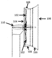
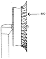
도 1은 하나 이상의 터빈 블레이드에 고정되고 이와 함께 회전 가능한 디퓨저의 측면도이다.
도 2는 도 1의 디퓨저에서의 슬롯 갭들의 예시적인 확대도이다.
도 3은 슬롯 갭 구성의 다른 예시적인 도면이다.
도 4는 플레넘 챔버에 연결된 슬롯 갭의 예시적인 도면이다.
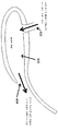
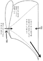
도 5는 와류 유도 시스템이 포함된 디퓨저 링의 예시적인 도면이다.
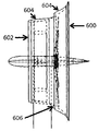
도 6은 흡기 슬롯 구성의 예시적인 도면이다.
도 7은 플레넘 챔버에 연결된 흡기 슬롯의 예시적인 도면이다.
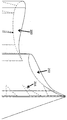
도 8은 회전 가능한 디퓨저 링의 업스트림에 위치한 정적 디퓨저 링을 갖는 디퓨저의 실시예를 나타내고 있다.
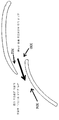
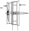
도 9는 회전 가능한 디퓨저 링의 다운스트림에 위치한 정적 디퓨저 링을 갖는 디퓨저의 실시예를 나타내고 있다.
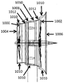
도 10은 다수의 풍력 터빈 로터를 갖는 풍력 터빈 구성을 예시적으로 나타내고 있다.
유사한 참조 부호는 첨부 도면에서 유사한 구성 요소를 나타내는 데 사용된다.The invention will be more clearly understood from the following detailed description described with reference to the accompanying drawings.
1 is a side view of a diffuser fixed to and rotatable with one or more turbine blades.
FIG. 2 is an exemplary enlarged view of slot gaps in the diffuser of FIG. 1. FIG.
3 is another exemplary diagram of a slot gap configuration.
4 is an exemplary view of a slot gap connected to the plenum chamber.
5 is an exemplary view of a diffuser ring incorporating a vortex induction system.
6 is an exemplary diagram of an intake slot configuration.
7 is an exemplary view of an intake slot connected to the plenum chamber.
8 shows an embodiment of a diffuser having a static diffuser ring located upstream of the rotatable diffuser ring.
9 shows an embodiment of a diffuser having a static diffuser ring located downstream of the rotatable diffuser ring.
10 exemplarily shows a wind turbine configuration having a plurality of wind turbine rotors.
Like reference numerals are used to refer to like elements in the accompanying drawings.
통상적인 대형 스케일의 수평 축 풍력 터빈들은 전력을 상업적으로 생산하기 위해서 풍력 발전 지역에서 사용된다. 유사한 수평 축 풍력 터빈들은 가령 전력을 소량으로 생산하기 위해서 가정 또는 사무실의 지붕과 같은 개인 건물 위에 배치된다. 이는 통상적으로 터빈 축에 위치한 발전기에 연결된 3 개의 블레이드형 터빈 로터를 포함한다.Conventional large scale horizontal axis wind turbines are used in wind farms to produce power commercially. Similar horizontal axis wind turbines are placed on private buildings, such as the roof of a home or office, for example to produce small amounts of electricity. It typically includes three bladed turbine rotors connected to a generator located on the turbine shaft.
바람이 풍력 터빈 로터의 블레이드를 거쳐서 흐를 때에, 양력이 블레이드에 의해서 생성되어 터빈 로터가 돌게 하고 이로써 부착된 전기 발전기로부터 전기가 생산된다(가령, 전기 발전기는 저속 구동 축, 기어 박스 및 발전기 축을 포함한다). 이로써, 터빈 로터가 회전하면, 기어 박스에 부착된 저속 구동 축을 회전시키고 이는 발전기 축을 전기를 생산하는 데 요구되는 속도로 회전시킨다.As wind flows through the blades of the wind turbine rotor, lift is generated by the blades, causing the turbine rotor to spin and thereby producing electricity from the attached electric generator (eg, the electric generator includes a low speed drive shaft, a gear box and a generator shaft). do). Thus, when the turbine rotor rotates, the low speed drive shaft attached to the gearbox rotates, which rotates the generator shaft at the speed required to produce electricity.
터빈 로터 블레이드에 의해서 생성된 항력은 그의 공격 각도 및 형상 함수일 수 있다.The drag generated by the turbine rotor blade can be a function of its attack angle and shape.
요 시스템(yaw system)이 사용되어 터빈 로터를 움직여 바람이 물어오는 방향으로 행하도록 하고 이로써 베츠(Betz)의 법칙에 의해서 가능한 최고의 효율을 달성하게 된다. 이러한 포인팅 동작은 가령 풍력 베인을 사용하여 수동으로 이루어지거나 가령 컴퓨터 제어형 요 제어 시스템을 사용하여 능동적으로 이루어질 수 있다.A yaw system is used to move the turbine rotor in the direction of the wind, thereby achieving the highest possible efficiency under Betz's law. This pointing operation can be done manually, for example using wind vanes or actively, for example using a computer controlled yaw control system.
공기 흐름을 수평 축 풍력 터빈을 향하게 하고 이를 중심으로 증가시키기 위해서 디퓨저가 풍력 터빈에 부착될 수 있다. 시스템 효율은 터빈 로터 면을 통해 공기를 초 가속화시킴으로해서 이론적인 베츠(Betz)의 법칙의 한계치를 초과할 수 있다. 이는 출구에서 공기 압력을 감소시켜 터빈을 통해 공기가 가속화되게 함으로써 컴팩트한 확산 시스템을 통해서 공기를 추출함으로써 달성될 수 있다. 따라서, 출구에서 공기 압력을 줄이게 되면 이에 대응하여 입구에서 공기 속도가 증가하며 이로써 동력 출력 및 효율이 증가하게 된다.Diffusers may be attached to the wind turbine to direct air flow towards and increasing the horizontal axis wind turbine. System efficiency can exceed the theoretical Betz's limit by accelerating air through the turbine rotor face. This can be accomplished by extracting air through a compact diffusion system by reducing the air pressure at the outlet to allow air to accelerate through the turbine. Thus, reducing the air pressure at the outlet increases the air velocity at the inlet correspondingly, thereby increasing power output and efficiency.
통상적인 디퓨저 부착형 풍력 터빈에 있어서의 주요한 실제 이슈는 효율을 크게 증대시키기 위한 속도로 공기를 가속화시키기 위해서 필요한 출구 면적을 크게 확장하면 카울링의 체적이 커져서 제어하기가 불편하고 큰 공기 역학 부하를 생성한다는 것이다. 이러한 카울링을 사용하면 증가된 항력이 발생하고 풍력 터빈 지지 타워 상의 부하가 증가하게 된다. 이러한 터빈을 위해서 필요한 제조 비용 및 공간이 크게 증가하게 된다. 또한 디퓨저의 가시성 프로파일(visibility profile)이 증가될 수 있는 데 이는 풍력 터빈이 많은 사람들에게 흉하게 보일 수 있기 때문에 바람직하지 않다.A major real issue for conventional diffuser-attached wind turbines is that the larger the outlet area needed to accelerate the air at a rate to significantly increase efficiency, the larger the volume of cowling, making it difficult to control and creating a large aerodynamic load. Is that. Using this cowling results in increased drag and an increased load on the wind turbine support tower. The manufacturing cost and space required for such a turbine is greatly increased. In addition, the visibility profile of the diffuser may be increased, which is undesirable because wind turbines may appear unpleasant to many.
용어 "디퓨저 링"이 본 명세서에서 사용될 때 이는 단면이 타원형 또는 특히 원형과 같은 임의의 적합한 구성과 관련된다. 2 개 이상의 디퓨저 링이 결합되어 사용될 때에, 이 링들은 서로 유체 연통 방식으로 되어 있으며 동축이거나 동축이 아닐 수도 있다.When the term “diffuser ring” is used herein it relates to any suitable configuration, such as oval or especially circular in cross section. When two or more diffuser rings are used in combination, they are in fluid communication with each other and may or may not be coaxial.
용어 "터빈 로터에 일체로 부착된 터빈 로터 카울링"이 본 명세서에서 사용될 때에, 이 용어는 다음과 같은 상황과 관련된다:When the term "turbine rotor cowling integrally attached to the turbine rotor" is used herein, the term relates to the following situation:
(1) 로터 카울링 및 터빈 로터는 서로 부착될 수 있는 개별 개체이다.(1) Rotor cowlings and turbine rotors are individual entities that can be attached to each other.
(2) 로터 카울링 및 터빈 로터는 단일체이다(가령, 몰드에 의해서 형성된 단일체이다).(2) Rotor cowling and turbine rotor are unitary (eg, unitary formed by a mold).
용어 "동적 디퓨저 링"이 본 명세서에서 사용될 때에, 이 용어는 풍력 터빈의 수평 축을 중심으로 회전할 수 있는 디퓨저 링에 관한 것이다.When the term "dynamic diffuser ring" is used herein, the term relates to a diffuser ring that can rotate about the horizontal axis of the wind turbine.
용어 "정적 디퓨저 링"이 본 명세서에서 사용될 때에, 이 용어는 풍력 터빈의 수평 축을 중심으로 회전할 수 없는 디퓨저 링에 관한 것이다.When the term "static diffuser ring" is used herein, the term relates to a diffuser ring that cannot rotate about the horizontal axis of the wind turbine.
용어 "슬롯 갭"이 본 명세서에서 사용될 때에, 이 용어는 디퓨저 링의 내부 표면과 외부 표면 간의 채널을 생성하도록 구성된 디퓨저 링의 구조를 통한 슬롯에 대한 것이다. 이와 달리 설명되지 않는 한, 슬롯 갭이 링을 2 개의 분리된 부분으로 분할하지 않는다면, 슬롯 갭은 디퓨저 링의 둘레의 임의의 부분을 덮을 수 있다. 가령, 디퓨저 링에서의 슬롯 갭(디퓨저 링의 구조적 통합성을 유지하면서)은 실질적으로 원주 또는 둘레에 형성될 수 있다.When the term "slot gap" is used herein, the term refers to a slot through the structure of the diffuser ring configured to create a channel between the inner surface and the outer surface of the diffuser ring. Unless otherwise stated, unless the slot gap divides the ring into two separate portions, the slot gap may cover any portion of the perimeter of the diffuser ring. For example, a slot gap in the diffuser ring (while maintaining the structural integrity of the diffuser ring) can be formed substantially circumferentially or around.
일반적으로, 슬롯 갭은 터빈 로터 면의 다운스트림에 위치하며 공기가 디퓨저 내로 들어가게 한다. 디퓨저 내로 들어간 공기는 저 에너지 후방 로터 공기를 재 에너지화하며 터빈 면 후방의 공기 압력을 저감시키고 이는 벤트리 효과에 의해서 공기를 터빈 로터를 통해서 가속화시킨다. 또한, 디퓨저 내에 들어간 공기는 경계 층 면적을 재 에너지화할 수 있다.In general, the slot gap is located downstream of the turbine rotor face and allows air to enter the diffuser. The air entering the diffuser reenergizes the low energy rear rotor air and reduces the air pressure behind the turbine face, which accelerates the air through the turbine rotor by the ventry effect. In addition, air entering the diffuser can reenergy the boundary layer area.
용어 "전체적으로 둘레에 형성된 슬롯 갭"이 본 명세서에서 사용될 때에, 이 용어는 디퓨저 링의 내부 표면과 외부 표면 간에 채널이 생성되도록 2 개의 디퓨저 링 간의 스페이서로서 기능하는 슬롯 갭에 관한 것이다.When the term “slot gap formed around the entirety” is used herein, the term relates to a slot gap that functions as a spacer between two diffuser rings such that a channel is created between the inner and outer surfaces of the diffuser ring.
전체적으로 둘레에 형성된 슬롯 갭은 터빈 로터 면의 업스트림 또는 다운스트림에 존재할 수 있다. 가령, 디퓨저 시스템은 로터와 함께 형성된 동적 디퓨저 링의 업스트림에 존재하는 정적 디퓨저 링 및 상기 동적 디퓨저 링의 다운스트림에 존재하는 다른 정적 디퓨저 링을 포함하며, 각 정적 디퓨저 링은 전체적으로 둘레에 형성된 슬롯 갭에 의해서 분리된다. 이와 달리, 동적 스핀 동적 디퓨저 시스템에서, 정적 디퓨저 링이 동적 디퓨저 링 간에 샌드위치되며 전체적으로 둘레에 형성된 슬롯 갭에 의해서 각각 분리된다.Slot gaps formed around the entirety may exist upstream or downstream of the turbine rotor face. For example, the diffuser system includes a static diffuser ring upstream of the dynamic diffuser ring formed with the rotor and another static diffuser ring downstream of the dynamic diffuser ring, each static diffuser ring having a slot gap formed around the entirety. Separated by. In contrast, in a dynamic spin dynamic diffuser system, the static diffuser rings are sandwiched between the dynamic diffuser rings and each separated by a slot gap formed around the entirety.
본 명세서에서 사용된 바와 같이, 슬롯 갭(또는 전체적으로 둘레에 형성된 슬롯 갭)은 축 방향으로(즉, 내부에서 외부로의 공기 흐름 방향으로) 점진적으로 감소하는 덕트 단면적을 생성하며 이로써 (디퓨저 내 또는 디퓨저의 다운스트림의 공기 압력에 비해서) 높은 압력의 공기를 디퓨저 링의 외부 또는 상부 표면에서 슬롯 갭을 통해서 디퓨저 링의 내부 또는 하부 표면으로 채널링함으로써 디퓨저 링의 내부 또는 하부 표면에 대해서 탄젠트 방향으로 또는 실질적으로 탄젠트 방향으로 고속의 공기가 주입되게 할 수 있다. 이는 경계 층을 재 에너지화하여 경계 층 성장 및 디퓨저 벽으로부터의 종국적 분리의 시작을 지연시킨다.As used herein, a slot gap (or a slot gap formed around the entirety) creates a duct cross-sectional area that gradually decreases in the axial direction (ie, in the direction of air flow from the inside to the outside) and thereby (in or within the diffuser). Relative to the air pressure downstream of the diffuser) in a tangent direction with respect to the inner or lower surface of the diffuser ring by channeling high pressure air from the outer or upper surface of the diffuser ring through the slot gap to the inner or lower surface of the diffuser ring It is possible to allow high velocity air to be injected substantially in the tangent direction. This re-energizes the boundary layer to delay boundary layer growth and the onset of eventual separation from the diffuser wall.
용어 “부분적 슬롯 갭”이 본 명세서에서 사용될 때에, 이 용어는 디퓨저 링의 내부 표면으로부터 오직 디퓨저 구조물의 부분적 두께를 통해서만 연장되는 슬롯 갭을 나타낸다.When the term “partial slot gap” is used herein, the term refers to a slot gap that extends only through the partial thickness of the diffuser structure from the inner surface of the diffuser ring.
용어 “공기 역학 힘”이 본 명세서에서 사용될 때에, 이 용어는 터빈 로터 블레이드에 걸쳐서 공기가 흐를 때에 생성되는 힘을 말한다. 용어 “양력”은 본 명세서에서 공기 흐름의 방향에 대해서 수직인 공기 역학적 힘의 성분을 말한다. 용어 “항력”은 본 명세서에서 공기 흐름의 방향에 대해서 평행인 공기 역학적 힘의 성분을 말한다.When the term “air dynamic force” is used herein, the term refers to the force generated when air flows over a turbine rotor blade. The term "lift" refers herein to a component of aerodynamic force that is perpendicular to the direction of air flow. The term "drag" refers herein to a component of aerodynamic forces that are parallel to the direction of air flow.
용어 “요(yaw)”가 본 명세서에서 사용될 때에, 이 용어는 터빈의 수직 축을 중심으로 한 풍력 터빈 로터의 움직임을 말한다.When the term “yaw” is used herein, the term refers to the movement of the wind turbine rotor about the vertical axis of the turbine.
용어 “나셀(nacelle)"은 본 명세서에서 사용될 때에, 이 용어는 수평 축을 중심으로 회전 가능하며 발전기 및/또는 기어 박스를 내장할 수 있는 터빈의 중심 축을 덮는 커버를 말한다.The term “nacelle”, as used herein, refers to a cover that is rotatable about a horizontal axis and covers a central axis of a turbine capable of embedding a generator and / or gearbox.
용어 "업스트림" 및 "다운스트림"은 본 명세서에서 공기 흐름에 대한 방향을 표시하는 데 사용될 수 있다.The terms "upstream" and "downstream" can be used herein to indicate a direction for air flow.
용어 "캠버(camber)"는 본 명세서에서 가령 에어로 포일의 곡률의 측정치와 같은 공기 역학적 캠버를 말한다. 이 캠버는 가령 에어로 포일의 상부 표면과 하부 표면 간의 중간에 있는 곡선인 캠버 라인을 사용하여 측정될 수 있다.The term "camber" refers herein to an aerodynamic camber, such as a measure of the curvature of an aero foil. This camber can be measured using a camber line that is, for example, a curve that is halfway between the top and bottom surfaces of the aero foil.
용어 "공탄성 재료"는 본 명세서에서 풍력 부하 하에서 예측 가능한 제어형 변형을 생성하는 재료를 말한다. 사용될 수 있는 공탄성 재료의 비제한적인 예로는 카본 섬유, 섬유 강화 복합재, 금속 매트릭스 복합재, 에폭시계 복합재, 열가소성 복합재, 알루미늄, 직물, 압전 재료 또는 임의의 적합한 공탄성 재료 및 이들의 임의의 조합이 포함된다.The term "aeroelastic material" refers herein to a material that produces a controlled deformation that is predictable under wind loads. Non-limiting examples of aeroelastic materials that can be used include carbon fibers, fiber reinforced composites, metal matrix composites, epoxy based composites, thermoplastic composites, aluminum, textiles, piezoelectric materials or any suitable aeroelastic materials and any combination thereof. Included.
용어 "스톨링(stall)"은 본 명세서에서 공격 각도가 증가함에 따라서 터빈 로터 블레이드에 의해서 생성되는 양력 저감을 말한다(공격 각도는 가령 코드 라인(chord line)과 같은 터빈 로터 블레이드 상의 기준 라인과 터빈 로터 블레이드와 터빈 로터 면을 통해 움직이는 공기 간의 상대적 이동을 나타내는 벡터 간의 각도이다). 임계 공격 각도를 넘어서면 항력보다 작은 양력이 생성된다.The term "stall" refers herein to lift reduction produced by the turbine rotor blades as the attack angle increases (the angle of attack is a reference line on the turbine rotor blades, such as a chord line, and a turbine). Angle between the vector representing the relative movement between the rotor blades and the air moving through the turbine rotor face). Beyond the critical attack angle, a lift less than drag is generated.
용어 "피칭(pitch)"은 본 명세서에서 터빈 로터 블레이드의 공격 각도를 바람 방향으로 향하게 하거나 바람 방향으로 향하지 않게 하여서 동력의 생성 또는 흡수를 제어하는 것을 나타낸다. The term "pitch" refers herein to controlling the generation or absorption of power by directing or not facing the angle of attack of the turbine rotor blades in the wind direction.
용어 "실질적으로 방사 방향"은 본 명세서에서 디퓨저의 중심점으로부터 외부로 연장되는 디퓨저 또는 풍력 터빈의 성분이다. 그러나, 디퓨저의 성분은 그 프로파일에 있어서 선형으로 될 필요는 없다.The term "substantially radial direction" is herein a component of a diffuser or wind turbine that extends outward from the center point of the diffuser. However, the components of the diffuser need not be linear in their profile.
본 실시예들이 본 명세서에서 디퓨저 부착형 풍력 터빈에서 구현되는 것으로 기술되고 예시되겠지만, 기술되는 시스템들은 오직 예시적일 뿐 한정적이지 않다. 본 기술 분야의 당업자들이 인정하듯이, 본 실시예들은 다양한 상이한 타입의 덕트형 로터에서 이용될 수 있다.While the embodiments are described and illustrated herein as being implemented in a diffuser attached wind turbine, the systems described are only illustrative and not restrictive. As will be appreciated by those skilled in the art, the present embodiments can be used in a variety of different types of ducted rotors.
공기가 디퓨저 부착형 풍력 터빈의 표면상에서 흐를 때, 공기의 경계 층이 생성된다. 이 경계 층은 디퓨저의 표면에 근접한 근사 정지 공기와 자유 유동 속도로 움직이는 어느 정도 떨어져 있는 공기 간의 전이 구역이다. 이 경계 층의 최대 두께는 통상적으로 공기 흐름 속도가 자유 유동 속도의 99%인 터빈 로터 블레이드로부터의 거리에 의해서 규정된다. 터빈 로터 블레이드의 프로파일에 의존하여, 공기는 많은 표면을 가로질러서 얇은 경계 층에서 순조롭게 흐르게 될 것이다.As air flows on the surface of a diffuser-attached wind turbine, a boundary layer of air is created. This boundary layer is the transition zone between the approximate stationary air proximate the surface of the diffuser and some spaced air moving at free flow velocity. The maximum thickness of this boundary layer is typically defined by the distance from the turbine rotor blades where the air flow rate is 99% of the free flow rate. Depending on the profile of the turbine rotor blades, air will flow smoothly in a thin boundary layer across many surfaces.
경계 층은 흐름 분리 과정에서 디퓨저 부착형 풍력 터빈의 표면으로부터 분리되는 경향이 있다. 터빈 로터 블레이드에 대한 경계 층의 속도가 거의 제로에 가까우면 흐름 분리가 발생하게 된다. 공기의 유체 흐름은 블레이드의 표면으로부터 분리되면서 와류의 형태를 취한다. 이러한 흐름 분리는 정체된 공기 버블이 분리 층 아래에서 형성되게 하고 항력을 더 생성한다. 이렇게 항력이 크게 증가하면 효율이 저하되고 로터가 스톨링될 수 있다. 정체된 공기 버블은 하나 이상의 터빈 로터 블레이드가 분리 지점을 다운스트림으로 이동시키도록 성형함으로써 저감되거나 제거될 수도 있다.The boundary layer tends to separate from the surface of the diffuser-attached wind turbine during flow separation. Flow separation occurs when the velocity of the boundary layer relative to the turbine rotor blades is near zero. The fluid flow of air separates from the surface of the blade and takes the form of a vortex. This flow separation causes stagnant air bubbles to form below the separation layer and create more drag. This drastic increase in drag can reduce efficiency and stall the rotor. Stagnant air bubbles may be reduced or eliminated by shaping one or more turbine rotor blades to move the separation point downstream.
경계 층의 정확한 성질은 터빈 로터 블레이드 구성과 공기 흐름 및 공기 속도가 포함된 다수의 요인들에 의존한다. 그러나, 경계 층은 층형이거나 터뷸런스형일 수 있다. 공기 포일 스톨링의 발달 뿐만 아니라 경계 층 내에서의 흐름의 세부 사항들은 대상의 스킨 마찰 항력 및 고속 흐름에서 발생하는 열 전달을 포함하는 공기 역학에서의 많은 문제점을 해결하는 데 매우 중요하다. 본 기술 분야의 당업자가 경계 층 물리학 개념에 익숙할 지라도, 보다 자세한 사항들은 가령 Landau & Lifshitz, 1987, Fluid Mechanics, 2nd edn, Chapter 4, Butterworth-Heinemann에서 확인할 수 있다.The exact nature of the boundary layer depends on a number of factors including turbine rotor blade configuration and air flow and air velocity. However, the boundary layer can be stratified or turbulent. The development of air foil stalling, as well as the details of the flow within the boundary layer, are critical to solving many problems in aerodynamics, including the skin friction drag of the object and heat transfer occurring at high velocity flows. Although those skilled in the art are familiar with the concept of boundary layer physics, more details can be found in Landau & Lifshitz, 1987, Fluid Mechanics, 2nd edn, Chapter 4, Butterworth-Heinemann.
디퓨저는 터빈 로터를 둘러싸는 카울링을 형성하도록 구성된 디퓨저 링을 포함하며, 터빈 로터는 하나 이상의 터빈 블레이드를 포함한다. 터빈 카울링은 터빈 로터에 고정되고 이와 함께 회전 가능하며, 이로써 터빈 카울링의 내부 표면이 하나 이상의 터빈 블레이드에 부착된다(가령, 터빈 블레이드의 선단에 부착된다).The diffuser includes a diffuser ring configured to form a cowling surrounding the turbine rotor, wherein the turbine rotor includes one or more turbine blades. The turbine cowling is fixed to and rotatable with the turbine rotor, whereby the inner surface of the turbine cowling is attached to one or more turbine blades (eg, attached to the tip of the turbine blade).
본 명세서에서 사용되는 용어 "부착된다"가 로터 블레이드에 연결되거나 일체화되는 경우를 의미하면, 카울링 및 로터는 단일 모듈로 형성될 수 있다. 디퓨저 링은 디퓨저 링의 후미 에지에 구성된 하나 이상의 와류 유도 장치를 포함할 수 있다. 이 와류 유도 장치는 터빈 블레이드의 다운스트림에서 미세 구조 와류를 생성하고 이는 터빈 로터 면 후방에서 압력을 저감시킨다. 이러한 터빈 로터 면 후방에서의 공기 압력 저감은 터빈 블레이드를 통한 공기 흡기를 증가시키고 이로써 출력 효율을 증대시킨다. When the term "attached" as used herein refers to the case where it is connected or integrated with a rotor blade, the cowling and the rotor may be formed as a single module. The diffuser ring may comprise one or more vortex induction devices configured at the trailing edge of the diffuser ring. This vortex induction device creates a microstructure vortex downstream of the turbine blades, which reduces the pressure behind the turbine rotor face. This air pressure reduction behind the turbine rotor face increases air intake through the turbine blades and thereby increases power efficiency.
하나 이상의 와류 유도 장치들은 추가적인 블레이드 선단 또는 팁 역할을 하여 공기 흐름 내에 위치할 때 이 와류 유도 장치가 로터 및 부착된 카울링을 회전시키기 위한 추가 토크를 제공하도록 동작한다.One or more vortex guiding devices serve as additional blade tips or tips to operate when the vortex guiding device provides additional torque to rotate the rotor and attached cowling when positioned in the air stream.
디퓨저 링은 하나 이상의 슬롯 갭을 포함할 수 있다. 하나 이상의 슬롯 갭은 높은 에너지의 공기가 디퓨저의 외부로부터 터빈 면 후방의 디퓨저 내로 진입하게 하여 저 에너지의 후방 회전 공기를 재 에너지화시킨다. 이론에 국한될 필요가 없이, 회전 가능한 디퓨저 링은 하나 이상의 슬롯 갭과 함께 터빈 면 후방에서의 하나 이상의 와류 생성을 용이하게 할 수 있다. 이러한 와류는 압력을 강하시키고 이로써 공기가 벤추리 효과에 의해서 터빈 로터 면을 통해서 가속되게 할 수 있다. 터빈 면 후방에서의 공기의 재 에너지화는 공기 흐름 분리를 방지하며 디퓨저와 연관된 기생 항력을 저감시킨다.The diffuser ring may comprise one or more slot gaps. One or more slot gaps allow high energy air to enter the diffuser behind the turbine face from outside of the diffuser to reenergy the low energy rear rotating air. Without wishing to be bound by theory, the rotatable diffuser ring may facilitate the creation of one or more vortices behind the turbine face with one or more slot gaps. This vortex lowers the pressure and thereby allows air to be accelerated through the turbine rotor face by the Venturi effect. Re-energy of air behind the turbine face prevents airflow separation and reduces parasitic drag associated with the diffuser.
또한, 이러한 디퓨저 구성은 디퓨저 구조와 연관된 항력을 저감시킬 수 있다. 이러한 디퓨저 구성은 다음으로 국한되지 않지만 실린더형, 원뿔 형, 타원형 구성과 같은 임의의 적합한 구성일 수 있다.In addition, this diffuser configuration can reduce drag associated with the diffuser structure. Such diffuser configurations may be any suitable configuration such as, but not limited to, cylindrical, conical, elliptical configurations.
디퓨저는 적어도 그 일부가 공탄성 재료로 구성될 수 있다. 일 실시예에서, 디퓨저는 하나 이상의 공탄성 플랩(aero-elastic flap)으로 구성될 수 있다. 디퓨저의 변형은 지배적인 풍속에 따라서 공기 흐름 스톨링이 낮은 풍속에서는 방지되고 높은 풍속에서는 실현되게 할 수 있다. 저 풍속 조건(가령, 20m/s)에서는, 공기 흐름 스톨링을 방지하는 것은 공격 각도를 저감시키도록 디퓨저를 조절하는 것을 포함할 수 있다. 가령, 디퓨저는 공기 흐름이 풍력 터빈의 로터 블레이드의 선단부를 향하도록 조절될 수 있다. 풍속에 의존하여 디퓨저를 상이한 공기 역학 구성으로 수동으로 공탄성 방식으로 조절하면, 풍력 터빈이 저 풍속에서도 여전히 전기를 계속해서 생산하게 할 수 있다. 가령 20 m/s보다 큰 고 풍속에서는, 공기 흐름 스톨링을 유도하는 것이 가령 공격 각도가 증가하도록 디퓨저를 조절하는 것을 포함할 수 있다. 공기 흐름 스톨링 유도 동작은 디퓨저를 통한 공기 흐름 및/또는 항력을 저감시켜서 고 풍속에서도 해당 구조물을 보호하는 데 사용된다. 또한, 공탄성 조절은 터빈 디퓨저에 의해서 유도된 항력의 양을 저감시키는 데 사용될 수도 있다.The diffuser may be at least partially composed of an aeroelastic material. In one embodiment, the diffuser may consist of one or more aero-elastic flaps. The deformation of the diffuser may allow air flow stalling to be avoided at low wind speeds and realized at high wind speeds depending on the prevailing wind speed. At low wind speed conditions (eg, 20 m / s), preventing air flow stalling may include adjusting the diffuser to reduce the angle of attack. For example, the diffuser may be adjusted such that the air flow is directed to the tip of the rotor blades of the wind turbine. Depending on the wind speed, manually adjusting the diffuser to a different aerodynamic configuration allows the wind turbine to continue to produce electricity at low wind speeds. At high wind speeds, for example greater than 20 m / s, inducing air flow stalling may include adjusting the diffuser to, for example, increase the attack angle. Airflow stalling induction is used to protect the structure at high wind speeds by reducing airflow and / or drag through the diffuser. Aeroelastic control may also be used to reduce the amount of drag induced by the turbine diffuser.
디퓨저 및/또는 터빈 로터 블레이드를 기계적으로 조절하는 시스템을 사용하기 보다는 디퓨저의 일부를 공탄성 재료로 구성함으로써 풍력 터빈의 복잡도가 저감되고 신뢰도가 증가하며 구성이 용이하게 된다. 가령, 피치가 변경되도록 풍력 터빈 로터 블레이드를 조절하는 것은 통상적으로 기계적 베어링 및/또는 선회 드라이브를 사용하여서 실행되었다. 선회 드라이브는 수압 또는 유압 또는 전기 시스템일 수 있다. 차단 시스템이 사용되어 터빈 로터 속도를 조절하거나 바람이 세서 위험한 경우나 모두 장치 유지를 위해서 로터를 중지시킬 수 있다. 이러한 시스템은 풍력 터빈의 복잡성을 증대시키며 바람이 매우 강한 경우에 블레이드의 피치를 신속히 변경하지 못한다. 이러한 복잡한 선회 및 차단 시스템은 고장이 날 수 있으며 이로써 고 풍속의 경우에 터빈이 설계된 한계치를 초과한 경우에 발전기 과잉 가열 및/또는 풍력 터빈이 복구되지 못할 정도의 상태를 초래할 수도 있다. 터빈 블레이드 및 카울링 장치는 단일 피스 또는 작은 개수의 피스로 주조될 수 있으며 이로써 제조 비용이 저감되고 가령 공탄성 물질을 사용해서 구조적 통합성을 유지할 수 있다. 가령, 디퓨저는 디퓨저의 일부가 풍압 하에서 변형되도록 의도적으로 약하게 되거나 트리밍되어서 2 개의 구성 요소들을 연결하는 기계적 시스템의 단점을 극복한 공탄성 힌지 시스템을 포함할 수 있다.Rather than using a system to mechanically control the diffuser and / or turbine rotor blades, part of the diffuser is made of aeroelastic material, which reduces wind turbine complexity, increases reliability, and facilitates configuration. For example, adjusting the wind turbine rotor blades to change pitch has typically been carried out using mechanical bearings and / or swing drives. The swing drive can be a hydraulic or hydraulic or electrical system. Shut-down systems can be used to regulate the turbine rotor speed or stop the rotor for maintenance purposes, both in high winds and in hazardous situations. This system adds to the complexity of the wind turbine and does not change the pitch of the blades quickly in very strong winds. Such complex turn and shut-off systems can fail, resulting in generator overheating and / or wind turbines failing to recover if turbines exceed their designed limits at high wind speeds. Turbine blades and cowling devices can be cast in a single piece or a small number of pieces, thereby reducing manufacturing costs and maintaining structural integrity, for example using aeroelastic material. For example, the diffuser may comprise an aeroelastic hinge system in which part of the diffuser is intentionally weakened or trimmed to deform under wind pressure, thereby overcoming the disadvantages of a mechanical system connecting the two components.
다른 실시예에서, 로터 터빈 블레이드는 선택 사양적으로 적어도 그 일부가 공탄성 재료로 구성되어 풍압 하에서 그 변형이 제어될 수 있다. 터빈 로터 블레이드를 공탄성 재료로 구성함으로써 블레이드가 순간적 풍속 조건에 따라서 수동으로 조절되어 블레이드 피치 및 로터 속도를 조절하기 위해서 복잡한 기계적 시스템을 사용할 필요가 없게 된다.In other embodiments, the rotor turbine blades may optionally be constructed of at least a portion of an aeroelastic material so that deformation can be controlled under wind pressure. By configuring the turbine rotor blades with aeroelastic material, the blades are manually adjusted according to instantaneous wind speed conditions, eliminating the need for complicated mechanical systems to control blade pitch and rotor speed.
본 명세서에서 기술되는 터빈 로터 블레이드는 중앙 축 나셀의 후방 및 터빈의 주 수직 축의 다운스트림에 위치하며 상기 주 수직 축은 터빈이 요잉하는(yawing) 축이다. 일 실시예에서, 로터는 터빈이 사용될 시에 지지 타워의 다운스트림 측 상에 위치할 수 있다. 일 실시예에서, 터빈의 수직 요 축의 다운스트림에 있는 터빈 로터는 터빈 로터로 하여금 수동 요 시스템(passive yaw system)으로 기능하거나 상술한 바와 같은 수동 요 시스템의 일부로 기능하게 할 수 있다. 일 실시예에서, 터빈은 기계적 포인팅 시스템의 도움없이도 바람 방향으로 자유롭게 포인팅될 수 있으며 다른 수동 요 추적 시스템이 필요 없게 된다.The turbine rotor blades described herein are located behind the central axis nacelle and downstream of the main vertical axis of the turbine, the main vertical axis being the yawing axis of the turbine. In one embodiment, the rotor may be located on the downstream side of the support tower when the turbine is used. In one embodiment, the turbine rotor downstream of the vertical yaw axis of the turbine may allow the turbine rotor to function as a passive yaw system or as part of a passive yaw system as described above. In one embodiment, the turbine can be freely pointed in the wind direction without the aid of a mechanical pointing system and eliminates the need for another manual yaw tracking system.
본 명세서에서 기술된 바와 같은 디퓨저를 풍력 터빈에 부착함으로써 동일한 로터 직경을 갖는 고전적이면서 통상적인 풍력 터빈에 비해서 풍력 에너지를 전기 에너지로 변환하는 효율 이외에도 다수의 장점을 가질 수 있다. 상술한 바와 같이, 피크 출력이 방사상 속도 분포 제어를 통해서 풍속 및 로터 토크에 따라서 제어될 수 있다. 추가적인 특징이 웨이크 터뷸런스(wake turbulence)를 저감시켜 터빈이 다른 터빈에 보다 가까이 배치되도록 하기 위해서 디퓨저 내에 포함될 수 있다. 이는 육지 설치 및 특히 해양 설치 시에 있어서 경제적 이점을 제공할 수 있다. 웨이크 터뷸런스를 감소시키기 위해서 필요한 다수의 구성 요소들이 본 명세서에 기술될 것이다. 또한, 블레이드 선단 와류를 제어 또는 제거함으로써, 폐쇄된 로터 블레이드가 생성되는 다량의 노이즈 오염을 줄일 수 있다. 몇몇 실시예들에서, 본 명세서에 기술되는 디퓨저 시스템은 적합한 기존의 터빈 설치에도 사용될 수 있다.Attaching a diffuser as described herein to a wind turbine may have a number of advantages in addition to the efficiency of converting wind energy into electrical energy over classical and conventional wind turbines having the same rotor diameter. As described above, the peak output can be controlled according to the wind speed and the rotor torque through the radial speed distribution control. Additional features can be included in the diffuser to reduce wake turbulence, allowing the turbine to be placed closer to other turbines. This can provide economic advantages in land installations and especially in marine installations. A number of components needed to reduce wake turbulence will be described herein. In addition, by controlling or removing the blade tip vortex, it is possible to reduce the large amount of noise contamination in which the closed rotor blades are produced. In some embodiments, the diffuser system described herein can also be used for suitable existing turbine installations.
디퓨저는 상술한 바와 같은 하나 이상의 터빈 블레이드를 포함하는 터빈 로터에 연결될 수 있다. 몇몇 실시예에서, 디퓨저 및 터빈 로터는 단일 구조물로서 구성될 수 있다. 이와 달리, 디퓨저는 가령 기존의 터빈 설치 시에 터빈 로터 블레이드에 장착될 수 있다. 이 터빈 로터 블레이드는 다음과 같은 하나 이상의 특징을 가질 수 있다:The diffuser may be connected to a turbine rotor including one or more turbine blades as described above. In some embodiments, the diffuser and turbine rotor may be configured as a single structure. Alternatively, the diffuser can be mounted to the turbine rotor blades, for example in existing turbine installations. This turbine rotor blade can have one or more of the following characteristics:
a. 공기 흐름의 경계 층에서 터뷸런스를 유발하는 소정의 표면 마감 재료로 구성될 수 있다.a. It may consist of any surface finish material that causes turbulence in the boundary layer of the air flow.
b. 부분적으로 스캘로핑된 구조물을 가질 수 있다.b. It may have a partially scalped structure.
c. 터뷸레이터(turbulator)를 구비할 수 있다.c. It may have a turbulator.
d. 와류 생성기를 구비할 수 있다.d. Vortex generators may be provided.
이러한 특징들은 경계 층을 터뷸런스 내로 이동시켜 정체 현상을 방지하게 해 준다. 이러한 터뷸런스 경계 층은 보다 많은 에너지를 포함하여 보다 큰 강도의 음의 압력 구배에 도달할 때까지 흐름 분리를 지연시키고 이로써 흐름 분리 지점을 다운스트림 방향으로 더 효율적으로 이동시키고 가능하게는 흐름 분리를 완벽하게 제거할 수도 있다.These features allow the boundary layer to move into the turbulence to prevent congestion. This turbulence boundary layer contains more energy to delay flow separation until a higher intensity negative pressure gradient is reached, thereby moving the flow separation point more efficiently in the downstream direction and possibly perfecting the flow separation. Can be removed.
터뷸레이터는 기계적 터뷸레이터(가령, 터빈 로터 블레이드에 부착된 지그 재그 스트립)이거나 공압 터뷸레이터(가령, 공기를 경계 층으로 불기 위해서 터빈 로터 블레이드 표면에 형성된 소형 구멍들)일 수 있다.The turbulator may be a mechanical turbulator (eg, a zig-zag strip attached to the turbine rotor blade) or a pneumatic turbulator (eg, small holes formed in the turbine rotor blade surface to blow air into the boundary layer).
와류 생성기는 디퓨저의 내부 표면 또는 터빈 로터 블레이드에 부착된 소형 베인(vane) 또는 범프(bump)일 수 있다. 와류 생성기는 에너지가 있는 급하게 움직이는 공기를 저속의 경계 층으로부터 터빈 로터 블레이드와 접촉하게 하여 경계 층을 재 에너지화시키는 와류를 생성한다.The vortex generator can be a small vane or bump attached to the inner surface of the diffuser or turbine rotor blades. Vortex generators bring energized, rushing air into contact with the turbine rotor blades from the low speed boundary layer to produce a vortex that reenergizes the boundary layer.
일 실시예에서, 와류 생성기는 그 단면이 직사각형 또는 삼각형이다. 와류 생성기는 경계 층의 부분적 두께와 동일한 두께를 가질 수 있다. 가령, 와류 생성기는 경계 층의 50 내지 90 %의 두께를 가질 수 있다. 와류 생성기는 국부적 공기 흐름에 대해서 공격 각도를 갖도록 위치할 수 있다.In one embodiment, the vortex generator is rectangular or triangular in cross section. The vortex generator can have a thickness equal to the partial thickness of the boundary layer. For example, the vortex generator can have a thickness of 50 to 90% of the boundary layer. The vortex generator can be positioned to have an attack angle with respect to the local air flow.
본 명세서에서 기술되는 디퓨저 부착형 풍력 터빈은 육지 기반의 터빈으로 한정되지 않는다. 디퓨저 부착형 터빈은 해상 부동 터빈과 같은 해양 풍력 터빈과 같이 바다에 설치될 수도 있다. 또한, 본 발명의 디퓨저 부착형 풍력 터빈은 가령 테더드형 터빈(tethered turbine)과 같은 공중 터빈일 수 있다. 가령, 디퓨저는 터빈을 부양시키기 위해서 가령 헬륨과 같은 공기보다 가벼운 재료로 채워진 블래더(bladder)와 같은 부양 구성 요소를 추가적으로 포함할 수 있다.The diffuser-attached wind turbines described herein are not limited to land-based turbines. Diffuser-attached turbines may be installed at sea, such as offshore wind turbines such as offshore floating turbines. In addition, the diffuser-attached wind turbine of the present invention may be an aerial turbine, such as a tethered turbine. For example, the diffuser may further include a flotation component, such as a bladder, filled with a lighter material than air, such as helium, to support the turbine.
도 1은 하나 이상의 터빈 로터 블레이드(102)에 고정되고 이와 함께 회전 가능한 디퓨저(100)를 나타내고 있다(본 명세서에서 기술된 바와 같이, 디퓨저(100)는 선택 사양적으로 터빈 로터의 일부로 형성될 수 있다). 공기는 입구(104)를 통해서 들어가고 출구(106)를 통해서 디퓨저를 나오게 된다. 이 디퓨저는 입구 및 출구를 포함하는 제1 디퓨저 링으로 형성될 수 있다. 도 1의 실시예에서, 디퓨저(100)는 터빈 로터 카울링을 포함하며, 이 터빈 로터 카울링은 터빈 로터에 일체로 부착되어 풍력 터빈의 수평 축을 둘러서 회전 가능한 유닛을 형성하도록 구성된다. 이 터빈 로터는 1 개 내지 10 개의 터빈 로터 블레이드, 가령 1 개 내지 4 개의 터빈 로터 블레이드, 가령 3 개의 터빈 로터 블레이드와 같은 하나 이상의 터빈 로터 블레이드를 포함한다. 하나 이상의 이 터빈 로터 블레이드는 터빈 로터 카울링(100)의 내부 표면에 연결되도록 구성되며 이로써 터빈 로터 카울링은 이 터빈 로터 블레이드와 함께 회전하게 된다(가령, 터빈 로터 카울링은 터빈 로터 블레이드의 선단에 연결된다). 이 풍력 터빈 로터 블레이드는 공격 각도를 증가 또는 감소시키도록 풍속에 따라서 조절될 수 있다. 디퓨저는 또한 고정되거나 회전 가능한 중심 축(110)을 포함할 수 있다. 특정 와류 유도 기하 구조를 갖는 디퓨저 카울링 후미 에지가 회전하면 디퓨저 출구의 다운스트림에서 와류가 발생하게 된다. 이로써, 출구 공기 압력이 저감되어 로터 면을 통해서 공기 속도가 증가하게 된다.1 illustrates a
디퓨저는 선택 사양적으로 전술한 바와 같은 하나 이상의 슬롯 갭(108)을 더 포함하며 이 하나 이상의 슬롯 갭은 디퓨저의 외부로부터의 공기와 디퓨저의 내부로터의 공기의 혼합을 구현하며 이로써 디퓨저 내에서 공기를 재 에너지화하여 압력을 저감시키고 흐름 분리를 저감시킨다. 하나 이상의 슬롯 갭은 제1 디퓨저 링의 전체 두께에 걸쳐서 연장된다. 가령, 디퓨저는 도 1에 도시된 바와 같이 플레어(flare) 형태로 구성될 수 있다. 터빈 면 후방에서의 디퓨저 체적 확장은 터빈 면 후방에서의 압력 저감에 기여한다. 디퓨저 회전에 의해서 터빈 면 후방에서 와류가 생성되면 공기 흐름 혼합을 촉진하고 흐름 분리를 지연시킨다.The diffuser optionally further comprises one or
제1 디퓨저 링 또는 다른 디퓨저 링 상에 추가적인 슬롯 갭이 존재할 수 있으며, 선택 사양적으로 이러한 추가적인 슬롯 갭은 부분적 슬롯 갭일 수 있다(즉, 이러한 부분적 슬롯 갭은 오직 디퓨저의 내부 표면 상에서의 출구를 가지며 디퓨저 링의 구조의 오직 일부분에만 걸쳐서 연장된다). 이러한 부분적 두께에 걸쳐서 연장된 슬롯 갭은 플레넘 챔버에 연결될 수 있다. 공기는 플레넘 챔버로부터 펌핑되어 디퓨저 링의 내부 표면 상의 슬롯 갭을 통과하여 디퓨저를 통과하는 공기 흐름으로 될 수 있다. 고속으로 이동하는 펌핑된 공기는 그 후방의 저속으로 이동하는 경계 층 공기를 흡기하며 이로써 저속 공기가 가속될 수 있다. 이로써, 디퓨저를 통한 공기 흐름을 증가시킬 수 있다. 공기는 가령 외부 전원을 갖는 컴프레서와 같은 능동 펌핑 시스템, 수압이나 유압 시스템 또는 다른 기계적 시스템에 의해서 펌핑될 수 있다. 플레넘 챔버는 디퓨저 링의 외부 표면 상에 출구를 가질 수 있으며 이로써 디퓨저의 외부로부터 플레넘 챔버로의 공기 펌핑이 이루어질 수 있다.There may be additional slot gaps on the first diffuser ring or other diffuser ring, optionally such additional slot gaps may be partial slot gaps (ie, such partial slot gaps only have an outlet on the inner surface of the diffuser Extending only over a portion of the structure of the diffuser ring). Slot gaps extending over this partial thickness may be connected to the plenum chamber. Air can be pumped from the plenum chamber and into the air flow through the diffuser through a slot gap on the inner surface of the diffuser ring. Pumped air moving at high speed intakes boundary layer air moving at low speed behind it, thereby allowing the low speed air to be accelerated. This may increase the air flow through the diffuser. The air may be pumped by, for example, an active pumping system such as a compressor with an external power source, a hydraulic or hydraulic system or other mechanical system. The plenum chamber may have an outlet on the outer surface of the diffuser ring, thereby allowing air pumping from the outside of the diffuser to the plenum chamber.
본 명세서에서 개시된 슬롯 갭은 축 방향에서 점진적으로 감소하는 총 덕트 단면적을 가질 수 있으며 이로써 (디퓨저로부터의 다운스트림에 있거나 디퓨저 내의 공기의 압력에 비해서) 높은 압력의 공기를 디퓨저 링의 외부 또는 상부 표면으로부터 슬롯 갭을 통해서 디퓨저 링의 내부 또는 하부 표면으로 채널링함으로써 디퓨저 링의 내부 또는 하부 표면에 대해서 탄젠트 방향으로 또는 실질적으로 탄젠트 방향으로 고속 공기의 주입을 실현한다. 이는 경계 층을 재 에너지화하며 이로써 디퓨저 벽의 덕트로부터의 경계 층 성장 및 종국적 흐름 분리의 시작을 지연시킬 수 있다.The slot gap disclosed herein may have a total duct cross-sectional area that decreases gradually in the axial direction, thereby allowing high pressure air (relative to the pressure of air in or downstream from the diffuser) to the outer or upper surface of the diffuser ring. Channeling from the through or through the slot gap into the inner or lower surface of the diffuser ring enables the injection of high velocity air in a tangent direction or substantially tangent to the inner or lower surface of the diffuser ring. This re-energizes the boundary layer, thereby delaying the onset of boundary layer growth and final flow separation from the duct of the diffuser wall.
본 발명의 국면에서, 디퓨저 링 내에 하나 이상의 플레넘 챔버들이 존재할 수 있으며, 각 챔버는 디퓨저 링의 둘레의 일부를 포함한다. 본 발명의 다른 국면에서, 디퓨저 링의 둘레의 큰 일부를 통해서 연장되는 단일 플레넘 챔버가 존재할 수 있다. 본 발명의 일 국면에서, 하나의 플레넘 챔버가 디퓨저 링의 둘레의 큰 일부를 포함하는 경우에, 이 플레넘 챔버는 이 디퓨저 링에 대해서 구조적 지지를 제공하도록 구성된 하나 이상의 파티션 또는 구획부들을 추가적으로 포함할 수 있다. 하나 이상의 플레넘 챔버가 포함되는 경우에, 펌핑 시스템은 선택 사양적으로 요구된 바와 같이 온 및 오프로 전환될 수 있다. 다른 실시예에서, 이 펌핑 시스템은 능동 펌핑이 아니라 수동으로 펌핑되는 수동 시스템일 수 있다.In an aspect of the invention, there may be one or more plenum chambers within the diffuser ring, each chamber comprising a portion of the perimeter of the diffuser ring. In another aspect of the invention, there may be a single plenum chamber extending through a large portion of the perimeter of the diffuser ring. In one aspect of the invention, where one plenum chamber comprises a large portion of the circumference of the diffuser ring, the plenum chamber further comprises one or more partitions or compartments configured to provide structural support for the diffuser ring. It may include. If more than one plenum chamber is included, the pumping system can be switched on and off as optionally required. In another embodiment, this pumping system may be a passive system that is pumped manually rather than active pumping.
도 2는 예시적인 슬롯 갭의 예시적인 확대도이다. 일 실시예에서, 디퓨저 링은 하나 이상의 슬롯 갭(200,202)을 포함하며, 각 슬롯 갭은 디퓨저 링의 내부 표면과 외부 표면 간의 채널을 생성한다. 슬롯 갭을 통과한 공기는 가령 흐름을 방해받지 않는 공기 흐름의 압력과 같은 자유 유동 값에 근사한 총 압력을 가질 수 있다. 하나 이상의 슬롯 갭은 고 에너지 공기 흐름이 디퓨저의 외부로부터 디퓨저 벽을 통하여서 디퓨저 내부로 들어가게 함으로써 고 에너지 공기 흐름이 디퓨저 내의 저 에너지 공기 흐름을 재 에너지화하는 것을 실현할 수 있다. 이로써 공기 흐름 분리가 방지되고 디퓨전이 개선될 수 있다. 하나 이상의 슬롯 갭은 높은 캠버링을 갖는 임의의 디퓨저 링의 내부 상의 영역 상에 위치할 수 있다. 높은 캠버를 갖는 디퓨저 내부의 영역 상에 슬롯 갭을 위치시키면 디퓨저를 통과한 저 에너지 공기와 슬롯 갭을 통과한 고 에너지 공기가 서로 혼합될 수 있다. 또한, 도 2에 도시된 바와 같이 복수의 와류 생성기(204)가 디퓨저 링의 후미 에지에 부착될 수 있다.2 is an exemplary enlarged view of an example slot gap. In one embodiment, the diffuser ring includes one or
도 3은 슬롯 갭의 다른 예시적인 실시예이다. 디퓨저의 외부로부터의 공기는 디퓨저 링의 외부 표면 상의 입구(300)를 통과한다. 슬롯 갭(302)은 축 방향에서 점진적으로 감소하는 총 덕트 단면적을 가지며 이로써 공기를 가속화시킨다. 이 고속 공기는 슬롯 갭(304)의 출구를 통해서 디퓨저 내부로 들어간다. 이 공기는 디퓨저의 내부 표면에 대해서 탄젠트 방향으로 슬롯 갭을 빠져나간다.3 is another exemplary embodiment of a slot gap. Air from the outside of the diffuser passes through an
도 4는 플레넘 챔버를 포함하는 부분적 슬롯 갭의 예시적인 실시예이다. 디퓨저의 외부로부터의 공기가 외부 표면 상의 입구(402)를 통해서 플레넘 챔버(402) 내로 들어간다. 이 공기는 입구(400)를 통해서 플레넘 챔버(402)로 능동적으로 펌핑되지만 시스템은 수동일 수 있다. 공기는 가령 부분적 슬롯 갭과 같은 출구(404)를 통해서 플레넘 챔버(402)를 나간다. 출구(404)는 디퓨저의 내부 표면에 대해서 탄젠트 방향으로 구성되어 있다. 이러한 공기 주입은 경계 층을 탄젠트 방향으로 또는 실질적으로 탄젠트 방향으로 재 에너지화하며 디퓨저 벽의 덕트로부터의 경계 층 성장 및 종국적 흐름 분리의 시작을 지연시킨다.4 is an exemplary embodiment of a partial slot gap that includes a plenum chamber. Air from the outside of the diffuser enters the
본 발명의 다른 국면에 따라서, 수평 축 풍력 터빈 디퓨저는 제1 디퓨저 링을 포함하며, 상기 제1 디퓨저 링은, 출구 및 입구와, 상기 제1 디퓨저 링의 후미 에지에 부착된 하나 이상의 와류 유도 장치를 포함하며, 상기 제1 디퓨저 링은 터빈 로터에 일체로 부착되어 상기 풍력 터빈의 수평 축을 중심으로 회전하는 유닛을 형성하는 터빈 로터 카울링을 형성하도록 구성될 수 있다. 상기 하나 이상의 와류 유도 장치들은 와류 유도 시스템을 형성할 수 있다. 상기 하나 이상의 와류 유도 장치들은 동적 공탄성 와류 유도 장치일 수 있다.According to another aspect of the invention, a horizontal axis wind turbine diffuser comprises a first diffuser ring, the first diffuser ring having an outlet and an inlet and at least one vortex induction apparatus attached to the trailing edge of the first diffuser ring. The first diffuser ring may be configured to form a turbine rotor cowling integrally attached to the turbine rotor to form a unit that rotates about a horizontal axis of the wind turbine. The one or more vortex induction devices may form a vortex induction system. The one or more vortex induction devices may be dynamic aeroelastic vortex induction devices.
일 실시예에서, 전술한 바와 같이, 하나 이상의 와류 유도 장치는 디퓨저 링의 후미 에지에 부착된다. 와류 유도 장치는 흐름에 개별적 국부적 회전을 부여하는 기하 구조를 갖는 장치이다. 와류 유도 장치는 핀, 소우-투스(saw-tooth), 커스프스(cusps)와 같은 와류를 생성할 수 있는 임의의 장치일 수 있다. 그러나, 본 명세서에서 기술되는 예시적인 기하 구조는 오직 예시적인 것일 뿐이며 다른 기하 구조들도 역시 사용될 수 있다. 와류 유도 장치는 디퓨저를 지나가는 고 에너지 공기 흐름을 디퓨저를 나가는 저 에너지 공기 흐름과 혼합시킴으로써 전술한 바와 같은 재 에너지화 기능을 실현할 수 있다. 가령, 와류 유도 장치는 디퓨저의 다운스트림에서 다수의 미세 와류를 생성할 수 있다. 이로써 항력이 유도되는 것이 저감된다.In one embodiment, as described above, one or more vortex induction devices are attached to the trailing edge of the diffuser ring. Vortex induction devices are devices with geometries that impart individual local rotations to the flow. The vortex induction device may be any device capable of generating vortices such as pins, saw-tooth, cusps. However, the example geometries described herein are illustrative only and other geometries may also be used. The vortex induction device can realize the re-energy function as described above by mixing the high energy air stream passing through the diffuser with the low energy air stream exiting the diffuser. For example, the vortex induction device can produce a number of fine vortices downstream of the diffuser. This reduces the drag induced.
가령, 와류 유도 장치의 선단은 디퓨저의 나머지부분보다 높은 정도의 스위프(sweep)를 가져서 디퓨저에 의해서 경험되는 유도 항력을 저감시킨다. 추가적으로 또는 이와 달리, 와류 유도 장치는 윙 선단 근방에서 국부적 이면각을 증가시키도록 위로 경사져서 미세 구조 와류를 생성하고 터빈 면 후방의 압력을 저감시키고 유도 양력에 의해서 유도되는 항력을 저감시킨다.For example, the tip of the vortex induction device has a higher degree of sweep than the rest of the diffuser, reducing the induced drag experienced by the diffuser. Additionally or alternatively, the vortex induction device is inclined upward to increase the local backside angle near the wing tip to produce microstructure vortices, reduce the pressure behind the turbine face and reduce drag induced by induced lift.
와류 유도 장치는 형태상 강성일 수 있다. 다른 실시예에서, 와류 유도 장치는 유도된 항력 저감 및 다양한 풍력 부하에서의 와류 유도를 최적화하도록 상이한 풍력 부하 하에서 동적으로 변형되도록 공탄성 특성을 가질 수도 있다.The vortex induction device can be rigid in shape. In other embodiments, the vortex induction device may have aeroelastic properties to be dynamically modified under different wind loads to optimize induced drag reduction and vortex induction at various wind loads.
도 5는 와류 유도 시스템을 포함하는 디퓨저 링의 예시적인 도면이다. 일 실시예에서, 와류 유도 시스템(500)은 동적 공탄성 와류 유도 장치일 수 있는 하나 이상의 와류 유도 장치를 포함한다. 일 실시예에서, 와류 유도 시스템은 그들을 감싸는 다수의 미세 구조 와류를 생성하여 단순한 기하 구조에서 구할 수 있는 압력보다 터빈 로터 면으로부터의 다운스트림에서 낮은 압력을 유도할 수 있다. 이러한 터빈 로터 면 후방에서의 압력 감소는 터빈 블레이드를 통한 흡기를 증가시키고 이로써 출력 효율을 증대시킨다. 와류 유도 장치는 도 5에 도시된 바와 같이 제1 디퓨저 링의 후미 에지에 부착될 수도 있지만, 디퓨저의 모든 후미 에지 또는 임의의 후미 에지에도 부착될 수도 있다.5 is an exemplary view of a diffuser ring including a vortex induction system. In one embodiment, the
하나 이상의 수정된 터빈 로터 블레이드(102), 슬롯 갭(302,400), 와류 생성기(204) 또는 와류 유도 시스템(500)은 디퓨저 상에서 유도된 항력을 저감시키고 풍력 터빈 시스템의 효율을 증대시키기 위해서 본 명세서에서 개시된 바와 같은 임의의 디퓨저와 함께 사용되거나 아니면 단독으로 사용될 수도 있다. 추가적으로, 디퓨저가 부착된 풍력 터빈 내에서 하나 이상의 이러한 특징 구성 요소들을 사용하면 다운스트림 웨이크 터뷸런스를 저감시킬 수 있다. 웨이크 터뷸런스는 터빈 로터 면 후방에서의 웨이크 와류 형성에 의해서 유발된다. 이렇게 웨이크 터뷸런스를 저감시키면 디퓨저가 부착되지 않은 터빈 또는 이러한 특징 구성 요소들이 없는 디퓨저 부착형 터빈에서보다 터빈이 보다 가깝게 위치할 수 있게 된다. 터빈을 서로 보다 가까이 위치시키면 효율이 증대되고 환경적 영향이 감소하고 통상적인 풍력 발전 지역의 비용도 저감된다. 가령, 효율이 증대되면 동일한 양의 전력이 통상적인 풍력 터빈 발전 지역에 대해서 요구되는 것보다 작은 대지 면적에서 생산될 수 있다(이는 대지 비용을 저감시키고 풍경에 대한 시각적 영향도 저감시킨다). 또한, 동일한 양의 대지에 대해서는 보다 많은 양의 전력이 생산되어 효율이 증대된다.One or more modified
본 명세서에서 제공되는 다른 국면에서는, 디퓨저는 풍력 터빈의 수평 축을 중심으로 회전 가능한 적어도 하나의 디퓨저 링 및 적어도 하나의 다른 추가적인 디퓨저 링을 가질 수 있다. 일 실시예에서, 이 적어도 하나의 다른 디퓨저 링은 정적 디퓨저 링(수평 축을 중심으로 회전하지 않는 링)일 수 있다.In another aspect provided herein, the diffuser may have at least one diffuser ring and at least one other additional diffuser ring rotatable about a horizontal axis of the wind turbine. In one embodiment, this at least one other diffuser ring may be a static diffuser ring (a ring that does not rotate about the horizontal axis).
다른 실시예에서, 전체적으로 둘레에 형성된 슬롯 갭에 의해서 각각이 분리되는 하나 이상의 다른 추가적인 디퓨저 링이 존재할 수 있다(이 추가적인 디퓨저 링은 동적 또는 특히 정적 디퓨저 링일 수 있다). 이 전체적으로 둘레에 형성된 슬롯 갭은 고 에너지 공기가 디퓨저로 들어가게 한다.In other embodiments, there may be one or more other diffuser rings, each separated by a slot gap formed around the entirety (this additional diffuser ring may be a dynamic or particularly static diffuser ring). The slot gap formed around this overall allows high energy air to enter the diffuser.
몇몇 실시예에서, 상기 하나 이상의 다른 디퓨저 링 각각의 입구 면적은 자신의 바로 업스트림에 있는 디퓨저 링의 출구 면적보다 작으며, 그 출구 면적은 그의 입구 면적보다 크거나 같다. 2 개 이상의 디퓨저 링을 갖는 일 실시예에서, 디퓨저 링의 총 출구 면적은 그의 단면적보다 클 수 있다.In some embodiments, the inlet area of each of the one or more other diffuser rings is less than the outlet area of the diffuser ring just upstream of it, and the outlet area is greater than or equal to its inlet area. In one embodiment having two or more diffuser rings, the total outlet area of the diffuser ring may be larger than its cross-sectional area.
디퓨저 링은 각 디퓨저 링이 다운스트림 방향에서 선행하는 디퓨저 링보다 낮은 공기 동력학적 캠버를 갖도록 구성될 수 있다. 일 실시예에서, 각 디퓨저 링은 다운스트림 방향에서 선행하는 디퓨저 링보다 낮은 캠버를 갖는다. 이론에 얽메일 필요 없이, 이로써 디퓨저 덕트가 기하학적으로 커지게 되고 이로써 출구 압력은 점진적으로 낮아 지게 된다.The diffuser ring may be configured such that each diffuser ring has a lower aerodynamic camber than the preceding diffuser ring in the downstream direction. In one embodiment, each diffuser ring has a lower camber than the preceding diffuser ring in the downstream direction. Without needing to be bound by theory, this results in a geometrically large diffuser duct, thereby gradually reducing the outlet pressure.
적어도 하나의 정적 디퓨저 링 및 상술한 바와 같은 디퓨저 링을 갖는 디퓨저 부착형 풍력 터빈은 하나 이상의 발전기를 포함할 수 있으며, 이 하나 이상의 발전기는 적어도 하나의 발전기 스테이터(stator) 및 하나 이상의 발전기 로터(rotor)를 포함하며, 이 스테이터 및 로터 중 어느 하나는 정적 디퓨저 링에 고정되거나 이 내에 포함되고 상기 스테이터와 로터 중 다른 하나는 동적 디퓨저 링에 고정되거나 이 내에 포함될 수 있다. 디퓨저 및 터빈 로터 블레이드 내에 포함된 발전기가 중심 축 내의 발전기를 대체하거나 이와 함께 사용될 수 있다.A diffuser-attached wind turbine having at least one static diffuser ring and a diffuser ring as described above may comprise one or more generators, the one or more generators comprising at least one generator stator and one or more generator rotors. Wherein either one of the stator and the rotor is fixed to or contained in the static diffuser ring and the other of the stator and the rotor may be fixed to or included in the dynamic diffuser ring. Generators contained within the diffuser and turbine rotor blades may replace or be used with generators in the central axis.
도 6을 참조하여 기술되는 일 실시예에서, 회전 가능한 디퓨저 링(600)은 정적 디퓨저 링(602)의 다운스트림에 위치한다. 회전 가능한 디퓨저 링(600) 및 정적 디퓨저 링(602)은 전술한 바와 같은 특징들 중 임의의 것들을 포함할 수 있다. 가령, 이 회전 가능한 디퓨저 링(600) 및 정적 디퓨저 링(602) 모두는 도시되지 않았지만 하나 이상의 와류 유도 장치를 포함할 수 있다. 이 회전 가능한 디퓨저 링(600) 및 정적 디퓨저 링(602) 모두는 전술한 바와 같은 슬롯 갭(604)을 포함할 수 있다. 전체가 둘레에 형성된 슬롯 갭(606)이 디퓨저 링 사이에 위치할 수 있다. 정적 디퓨저 링(602)은 또한 하나 이상의 가이드 베인을 포함할 수 있다. 도 6을 참조하여 기술되는 실시예에서, 가이드 베인은 사전 회전 가이드 베인(pre-rotation guide vane)이다. 가령, 사전 회전 가이드 베인은 디퓨저 내로 유입되는 공기 흐름에서의 트위스트를 저감시키고 이로써 터빈 면을 통한 공기의 효율을 증대시킬 수 있다. 다른 실시예에서, 가이드 베인은 에어 포일형일 수 있지만 이는 필수적인 사항은 아니며 임의의 다른 적합한 형상들이 사용될 수 있다. 가이드 베인은 디퓨저에 추가적인 구조적 지지력을 제공하도록 구성될 수 있다. 이러한 추가적 구조적 지지력은 가령 서로 상이한 풍력 부하로 인해서 디퓨저의 공탄성 변형을 촉진시킬 수 있다. 회전 가능한 디퓨저 링은 선택 사양적으로 입구 면적보다 큰 출구 면적을 가지며 이로써 터빈 면 후방의 공기 압력을 저감시킬 수 있다.In one embodiment described with reference to FIG. 6, the
일 실시예에서, 다수의 정적 디퓨저 링이 제1 회전 가능한 디퓨저 링의 다운스트림에 위치할 수 있다. 이 경우에, 정적 디퓨저 링은 출구 및 입구를 포함하며, 상기 각 다운스트림의 정적 디퓨저 링의 입구 면적은 바로 업스트림에 있는 정적 디퓨저 링의 출구 면적보다 작으며 각각의 정적 디퓨저 링의 출구 면적은 그 디퓨저 링의 입구 면적과 동일하거나 이보다 클 수 있다(가령, 각 디퓨저 링의 단면적 프로파일은 원뿔형이거나 실린더형일 수 있다). 가령, 각 디퓨저 링의 출구 면적은 그의 입구 면적보다 클 수 있다.In one embodiment, multiple static diffuser rings may be located downstream of the first rotatable diffuser ring. In this case, the static diffuser ring includes an outlet and an inlet, the inlet area of each of the downstream static diffuser rings is less than the outlet area of the static diffuser ring immediately upstream and the outlet area of each static diffuser ring is It may be equal to or greater than the inlet area of the diffuser ring (eg, the cross-sectional profile of each diffuser ring may be conical or cylindrical). For example, the outlet area of each diffuser ring can be larger than its inlet area.
본원에서 기술된 바와 같은 다수의 정적 디퓨저 링을 갖는 디퓨저 구성은 단면적을 크게 확장시킬 필요 없이 출구 면적을 크게 확장시킬 수 있다. 이로써, 공기는 터빈을 통해서 가속화되고 이로써 터빈의 크기 증대와 관련된 문제를 극복하면서 동시에 효율을 증대시킬 수 있다. 출구 면적 확장 정도는 입구 면적의 1.2 내지 10 배 정도일 수 있으며 가령 2 내지 5 배일 수 있으며 가령 2.5 내지 4.5배일 수 있다.Diffuser configurations with multiple static diffuser rings as described herein can greatly expand the outlet area without having to greatly expand the cross-sectional area. In this way, the air is accelerated through the turbine, thereby overcoming the problems associated with increasing the size of the turbine and at the same time increasing the efficiency. The extent of outlet area expansion can be on the order of 1.2 to 10 times the inlet area, for example 2 to 5 times and for example 2.5 to 4.5 times.
총 디퓨저 출구 면적의 제1 디퓨저 링 입구 면적에 대한 비는 최대 디퓨저 단면적의 제1 디퓨저 링 입구 면적에 대한 비보다 크다. 총 디퓨저 링 출구 면적의 제1 디퓨저 링 입구 면적에 대한 적합한 예시적인 비는 2:1, 2.5:1, 3.2:1, 4:1, 4.5:1, 3.2:1일 수 있으며 가령 2.1:1, 3.2:1일 수 있다.The ratio of the total diffuser exit area to the first diffuser ring inlet area is greater than the ratio of the maximum diffuser ring inlet area to the first diffuser ring inlet area. Suitable exemplary ratios of the total diffuser ring outlet area to the first diffuser ring inlet area may be 2: 1, 2.5: 1, 3.2: 1, 4: 1, 4.5: 1, 3.2: 1, such as 2.1: 1, 3.2: 1.
일 실시예에서, 하나 이상의 디퓨저 링은 하나 이상의 흡기 슬롯(suction slot)을 더 포함할 수 있다. 흡기 슬롯은 축 방향에서(즉, 공기 흐름 방향에서) 압축 노즐 기하 구조와 같은 점진적으로 증가하는 총 덕트 단면적을 가질 수 있으며, 경계 층은 이 흡기 슬롯에 의해서 탄젠트 방향으로 재 에너지화되지 않지만 실질적으로 수직으로 흡기되어 버린다. 이러한 흡기 슬롯들은 또한 선택 사양적으로 외부 통풍 구조물에 연결될 수 있다. 흡기 슬롯(디퓨저 링의 오직 일부만을 통해서 연장되는)은 부분적 두께의 흡기 슬롯일 수 있다. 부분적 두께 흡기 슬롯은 플레넘 챔버에 연결될 수 있다.In one embodiment, the one or more diffuser rings may further comprise one or more intake slots. The intake slot can have a progressively increasing total duct cross-sectional area in the axial direction (ie in the air flow direction), such as a compression nozzle geometry, and the boundary layer is not energized in the tangent direction by this intake slot but is substantially It is inhaled vertically. Such intake slots may also optionally be connected to an external ventilation structure. The intake slot (which extends through only a portion of the diffuser ring) can be a partially thick intake slot. The partial thickness intake slot may be connected to the plenum chamber.
도 7은 흡기 슬롯의 예시적인 도면이다. 일 실시예에서, 저 에너지 경계 층 공기가 흡기 슬롯 입구(700)를 통해서 디퓨저 외부로 유출된다. 이 공기는 디퓨저의 내부 표면에 대해서 수직으로 유출될 수 있다. 흡기 슬롯(702)의 확장은 흡기 슬롯을 나가는 공기의 압력을 저감시키고 이로써 벤츄리 효과에 의해서 저 에너지의 경계 층 공기를 디퓨저 외부로 나가게 할 수 있다. 디퓨저의 외부 표면 상에서 이동하는 고 에너지 공기는 저 에너지 공기와 혼합되어 이 저 에너지 공기를 에너지화함으로써 경계 층의 공기 유출을 돕는다.7 is an exemplary view of an intake slot. In one embodiment, low energy boundary layer air flows out of the diffuser through the
도 8은 플레넘 챔버에 연결된 부분적 흡기 슬롯의 예시적인 도면이다. 일 실시예에서, 저 에너지 경계 층 공기가 흡기 슬롯 입구(800)로부터 디퓨저 외부로 나간다. 이 공기는 디퓨저의 내부 표면에 대해서 수직으로 나갈 수 있다. 플레넘 챔버(802) 내의 압력은 기계적으로 저감되어서 플레넘 챔버를 진공으로 만들고 이는 공기를 흡기 슬롯으로 들어오게 한다. 이 공기는 통풍 구조물에 연결될 수 있는 슬롯 출구(804)를 통해서 플레넘 챔버를 나간다. 8 is an exemplary view of a partial intake slot connected to the plenum chamber. In one embodiment, low energy boundary layer air exits out of the diffuser from the
통풍 구조물들은 이 흡기 슬롯에 직접적으로 연결되거나 선택 사양적으로 슬롯 갭과 관련하여서 전술한 바와 같은 플레넘 챔버와 같은 플레넘 챔버를 통해서 흡기 슬롯에 연결될 수 있다. 본 발명의 다른 실시예에서, 공기는 상기 플레넘 챔버로부터 능동적으로 또는 수동적으로 흡기되어 디퓨저 링의 외부 표면 상의 하나 이상의 흡기 슬롯을 통과하여 터빈 면 후방의 공기 압력 저감을 도울 수 있다. 통풍 구조물이 디퓨저를 나가는 공기 유출로 인해서 디퓨저 상을 통과하는 공기의 고 에너지를 유발하도록 할 수 있다. 이러한 고 에너지 공기 흐름과의 상호 작용은 디퓨저를 나가는 공기의 전체 현상을 억제한다. 또한, 통풍 구조물은 그의 단면적이 증가될 필요가 없이 장치의 출구 면적을 증대시킨다. 또한, 통풍 구조물은 디퓨저 링을 플랩 구조물(flap structure)에 연결시킴으로써 구조적 통합성을 높이는 데 사용될 수 있다. 통풍 구조물은 설계상 비대칭적으로 되어 있어 링이 회전할 때 링 상의 토크 증가를 실현할 수 있다.Ventilation structures may be directly connected to this intake slot or optionally connected to the intake slot through a plenum chamber, such as the plenum chamber as described above in connection with the slot gap. In another embodiment of the present invention, air may be actively or passively inspired from the plenum chamber and passed through one or more intake slots on the outer surface of the diffuser ring to help reduce air pressure behind the turbine face. It is possible for the ventilation structure to cause high energy of the air passing over the diffuser due to the air outflow exiting the diffuser. This interaction with the high energy air stream suppresses the overall phenomenon of air exiting the diffuser. In addition, the ventilation structure increases the outlet area of the device without requiring its cross sectional area to be increased. Ventilation structures may also be used to increase structural integrity by connecting the diffuser ring to the flap structure. The ventilation structure is asymmetrical in design to realize an increase in torque on the ring as the ring rotates.
디퓨저에 부착된 통풍 구조물은 디퓨저의 외부 상에서 근소하게 요잉된(yawed) 풍력 상태를 포획하는 것을 도울 수 있다. 이로써 디퓨저 외부의 압력을 높일 수 있으며 보다 흡기 효율을 개선할 수 있다. 일 실시예에서, 통풍 구조물은 디퓨저의 외부 상에서의 고압 공기가 디퓨저 상에서 롤링하여 그 밑의 저압 공기로 들어가는 것을 방지함으로써 항력 증가를 방지한다. 또한, 통풍 구조물은 터빈의 요 정렬(yaw alignment)을 도울 수 있으며 따라서 대안으로 필요한 수동 바람 요 추적 시스템을 필요 없게 만들 수 있다. 수많은 현대의 풍력 터빈은 능동형의 요 추적 시스템을 구비하고 있으며 이러한 통풍 구조물을 사용하게 되면 능동적인 바람 추적이 더 개선될 수 있다.Ventilation structures attached to the diffuser may help to capture wind conditions that are slightly yawed on the exterior of the diffuser. This can increase the pressure outside the diffuser and improve the intake efficiency. In one embodiment, the vent structure prevents drag increase by preventing high pressure air on the exterior of the diffuser from rolling onto the diffuser and into the low pressure air beneath it. In addition, the ventilation structure can assist in the yaw alignment of the turbine and thus alternatively eliminate the need for the required manual yaw tracking system. Many modern wind turbines have an active yaw tracking system and the use of these ventilation structures can further improve active wind tracking.
통풍 구조물은 디퓨저로부터의 공기의 추출 정도를 증가시키기 위해서 능동 펌핑 시스템과 결합하여 사용될 수 있다. 다른 실시예에서, 통풍 구조물은 전술한 바와 같은 능동 또는 수동 펌핑형 슬롯 갭과 달리 고 에너지 블로잉(blowing) 슬롯 갭에 공기를 제공하기 위해서 사용될 수도 있다.The ventilation structure can be used in conjunction with an active pumping system to increase the degree of extraction of air from the diffuser. In other embodiments, the ventilation structure may be used to provide air to a high energy blowing slot gap, unlike the active or passive pumped slot gaps described above.
통풍 구조물 자체는 공격 각도에서 에어 포일로 제공되는 연장된 로터의 선단으로서 방사상으로 형상화될 수 있으며 이로써 자체적으로 어셈블리로부터의 추가적인 전달 가능한 토크를 생성한다.The ventilation structure itself can be radially shaped as the tip of an extended rotor provided to the air foil at the angle of attack, which in itself creates additional transferable torque from the assembly.
정적 디퓨저 링이 회전 가능한 디퓨저 링으로부터 다운스트림에 위치하는 실시예에서, 정적 디퓨저 링은 하나 이상의 통풍 구조물을 더 포함할 수 있다.In embodiments where the static diffuser ring is located downstream from the rotatable diffuser ring, the static diffuser ring may further include one or more ventilation structures.
도 9는 회전 가능한 디퓨저 링(900)이 정적 디퓨저 링(902)의 업스트림에 위치하는 실시예를 나타내고 있다. 도 9에 도시된 디퓨저 구성의 정적 디퓨저 링(902)은 선택 사양적으로 터빈 면 후방에 위치하는 미 도시된 하나 이상의 후방 회전 가이드 베인을 포함할 수 있다. 도 9에 도시된 디퓨저 구성은 선택 사양적으로, 증가된 출구 면적을 제공하여 터빈 면 후방에서 압력 저감을 크게 하는 흡기 통풍 구조물, 하나 이상의 와류 유도 장치, 디퓨저 링 내의 슬롯 갭, 디퓨저 링 간의 전체적으로 둘레에 형성된 슬롯 갭, 추가적인 정적 디퓨저 링과 같은 전술한 특징들(미 도시)을 모두 또는 이들 중 임의의 것을 포함할 수 있다. 디퓨저 실시예에서, 디퓨저 링은 전체가 둘레에 형성된 슬롯 갭에 의해서 서로 분리되며 이로써 공기가 디퓨저를 통과할 때 공기가 재 에너지화된다.9 illustrates an embodiment in which the
하나 이상의 터빈 로터가 존재하는 다른 실시예에서, 터빈 로터는 동일한 발전기 또는 서로 다른 발전기를 구동시키는 역 회전 로터일 수 있다. 2 개의 이상의 역 회전 로터는 복합한 기어링 및 요잉 메카니즘을 제거한다. 역 회전 터빈 로터는 발전기의 회전 속도를 증가시키는 데 사용될 수 있다. 일 실시예에서, 각 터빈 로터 내의 하나 이상의 터빈 로터 블레이는 후방 블레이드와 충돌하는 것을 피하기 위해 전방으로 근소하게 경사지게 형성될 수 있다. 다른 실시예에서, 하나 이상의 터빈은 서로 다른 직경을 가질 수 있다.In other embodiments in which one or more turbine rotors are present, the turbine rotors may be counter rotating rotors that drive the same generator or different generators. Two or more counter rotating rotors eliminate the complex gearing and yawing mechanism. The counterrotating turbine rotor can be used to increase the rotational speed of the generator. In one embodiment, one or more turbine rotor blades within each turbine rotor may be formed slightly inclined forward to avoid colliding with the rear blades. In other embodiments, one or more turbines may have different diameters.
일 실시예에서, 하나 이상의 터빈 로터 각각이 디퓨저 링에 고정되고 이와 함께 회전하며 이로써 디퓨저 링은 로터 주변의 터빈 카울링을 형성할 수 있다. 이들 디퓨저 링은 터빈 로터에 일체로 부착되어 상기 풍력 터빈의 수평 축을 중심으로 회전하는 유닛을 만드는 터빈 로터 카울링을 형성하도록 구성될 수 있다. 몇몇 다수의 로터 실시예에서, 전체 디퓨저는 회전 가능하다. 다른 실시예에서, 동적 디퓨저 링은 적어도 하나의 정적 구성 요소(가령, 정적 디퓨저 링)에 의해서 서로 분리될 수 있다. 가령, 2 개의 역 회전 로터가 존재하는 경우에, 2 개의 동적 디퓨저 링은 가령 정적 디퓨저 링과 같은 적어도 하나의 정적 구성 요소에 의해서 분리될 수 있다. 각 디퓨저 링은 전체적으로 둘레에 형성된 갭에 의해서 분리될 수 있다. 하나 이상의 다른 디퓨저 링은 출구 및 입구를 포함하며, 또한 이 하나 이상의 다른 디퓨저 링은 제1 디퓨저 링의 내부 표면으로부터 연장되고 제1 디퓨저 링의 전체 두께에 걸쳐서 연장되는 하나 이상의 슬롯 갭을 선택 사양적으로 포함할 수 있다.In one embodiment, each of the one or more turbine rotors is secured to and rotates with the diffuser ring such that the diffuser ring can form a turbine cowling around the rotor. These diffuser rings can be configured to form a turbine rotor cowling that is integrally attached to the turbine rotor to create a unit that rotates about the horizontal axis of the wind turbine. In some multiple rotor embodiments, the entire diffuser is rotatable. In other embodiments, the dynamic diffuser rings may be separated from each other by at least one static component (eg, static diffuser ring). For example, if there are two counter rotating rotors, the two dynamic diffuser rings can be separated by at least one static component, such as a static diffuser ring. Each diffuser ring may be separated by a gap formed around the entirety. The one or more other diffuser rings include an outlet and an inlet, wherein the one or more other diffuser rings optionally include one or more slot gaps extending from the inner surface of the first diffuser ring and extending over the entire thickness of the first diffuser ring. It may include.
도 10은 하나 이상의 터빈 로터 블레이드를 포함하는 제1 터빈 로터(1000) 및 하나 이상의 터빈 로터 블레이드를 포함하는 제2 터빈 로터(1002)가 미도시된 단일 중심 구동 축에 연결될 수 있는 실질적으로 동축형 로터 구성을 갖는 디퓨저 부착형 풍력 터빈의 측면도이다. 이 터빈 로터(1000,1002)는 디퓨저 링(1004,1006)에 각기 고정되며 각기 이들과 함께 회전 가능하다. 이로써, 각 디퓨저 링은 로터를 두르는 터빈 카울링을 형성한다. 회전 가능한 디퓨저 링은 정적 디퓨저 링(1003)에 의해서 분리될 수 있다. 각 디퓨저 링은 선택 사양적으로 하나 이상의 슬롯 갭(1010)을 포함한다. 전체가 둘레에 형성된 슬롯 갭(1012)은 디퓨저 링을 분리시킨다.10 is a substantially coaxial type in which a
도 1에서 도 10까지를 참조하여 본 명세서에서 기술된 디퓨저 실시예는 단지 예시적일 뿐이며 한정적으로 해석되어서는 안 된다. 잘아는 바와 같이, 회전 가능한 디퓨저의 임의의 적합한 조합, 가령 회전 대 회전 디퓨저 링 결합, 정적 대 회전 대 정적 디퓨저 결합, 회전 대 정적 대 회전 대 정적 디퓨저 결합 또는 그 이외의 조합들이 가능하다.The diffuser embodiments described herein with reference to FIGS. 1 through 10 are merely exemplary and should not be construed as limiting. As will be appreciated, any suitable combination of rotatable diffusers is possible, such as rotation to rotation diffuser ring coupling, static to rotation to static diffuser coupling, rotation to static to rotation to static diffuser coupling, or other combinations.
잘아는 바와 같이, 완전하게 회전 가능한 디퓨저를 사용하는 측면 및 부분적으로 회전 가능한 디퓨저를 사용하는 측면과 관련하여 본 명세서에서 기술된 바와 같은 디퓨저 구성은 또한 도 1에서 도 6까지를 참조하여 전술된 다른 특징들을 모두 또는 임의의 것들을 단독으로 또는 서로 결합하여 포함할 수도 있다.As will be appreciated, a diffuser configuration as described herein with respect to a side using a fully rotatable diffuser and a side using a partially rotatable diffuser is also described in detail with reference to FIGS. 1-6. All or any of the features may be included alone or in combination with each other.
본 명세서에서 주어진 임의의 범위 또는 장치 값들은 본 기술 분야의 당업자에게는 분명한 효과를 상실하지 않고서 확장 또는 변경될 수 있다.Any range or device values given herein may be extended or changed without losing obvious effects to those skilled in the art.
전술된 이점 및 장점들은 일 실시예와 연관되거나 몇몇 실시예와 연관될 수 있다는 사실을 잘 알 것이다. 실시예들은 진술된 문제들 중 임의의 것 또는 모두를 해결하는 것으로 한정되지 않으며 진술된 장점 및 이점들을 모두 또는 이들 중 임의의 것을 갖는 것으로 한정되지 않는다.It will be appreciated that the foregoing advantages and advantages may be associated with one embodiment or with some embodiments. The embodiments are not limited to solving any or all of the stated problems and are not limited to having all or any of the stated advantages and advantages.
명사의 단수형 사용은 그 복수형의 존재를 배제하지 않는다. 용어 "포함한다"는 본 명세서에서 해당 방법의 단계나 요소를 포함하는 것을 의미하되 열거되지 않은 단계나 요소들 이외의 단계나 요소의 존재를 배제하지 않는다.The singular form of the nouns does not exclude the presence of the plural. The term "comprising" is meant herein to include the steps or elements of the method, but does not exclude the presence of steps or elements other than steps or elements not listed.
본 명세서에서 기술되는 방법의 단계들은 임의의 적합한 순서로 또는 적절한 경우에는 동시에 수행될 수도 있다. 또한, 개별 단계들은 본 발명의 기술적 사상 및 범위를 벗어나지 않는 한 제거될 수도 있다. 전술한 실시예의 국면은 기술된 다른 측면들과 결합되어 본 발명의 효과를 상실하지 않으면서 다른 실시예들을 구성할 수 있다. 해당 방법의 단계나 요소는 열거된 목록을 한정적으로 포함하는 것이 아니라 이 방법 또는 장치는 다른 방법 또는 요소를 더 포함할 수도 있다.The steps of the methods described herein may be performed in any suitable order or where appropriate simultaneously. In addition, individual steps may be removed without departing from the spirit and scope of the invention. Aspects of the foregoing embodiments can be combined with other aspects described to constitute other embodiments without losing the effect of the invention. The steps or elements of the method do not include the enumerated list in a limited manner, but the method or device may further include other methods or elements.
잘 아시다시피 바람직한 실시예의 전술한 바는 오직 예시적으로 주어진 것이며 따라서 다양한 수정 및 변경이 본 기술 분야의 당업자에게 가능하다. 다양한 실시예가 특정 세부 사항 또는 하나 이상의 개별 실시예를 참조하여 전술되었지만, 본 기술 분야의 당업자는 본 발명의 사상 및 범위를 벗어나지 않으면서 이들 실시예에 대한 변경을 시도할 수 있다.As will be appreciated, the foregoing description of the preferred embodiment is given by way of example only, and various modifications and changes are possible to those skilled in the art. While various embodiments have been described above with reference to specific details or one or more individual embodiments, those skilled in the art may attempt to modify these embodiments without departing from the spirit and scope of the invention.
잘아는 바와 같이, 전술된 이점 및 장점들은 일 실시예와 연관되거나 몇몇 실시예와 연관될 수 있다는 사실을 잘 알 것이다. 실시예는 진술된 문제들 중 임의의 것 또는 모두를 해결하는 것으로 한정되지 않으며 진술된 장점 및 이점들을 모두 또는 이들 중 임의의 것을 갖는 것으로 한정되지 않는다.As will be appreciated, it will be appreciated that the advantages and advantages described above may be associated with one embodiment or with some embodiments. An embodiment is not limited to solving any or all of the stated problems and is not limited to having all or any of the stated advantages and advantages.
Claims (39)
상기 디퓨저는,
제1 디퓨저 링을 포함하며,
상기 제1 디퓨저 링은,
출구 및 입구와,
상기 제1 디퓨저 링의 후미 에지에 부착된 하나 이상의 와류 유도 장치를 포함하며,
상기 제1 디퓨저 링은 터빈 로터에 일체로 부착되어 상기 풍력 터빈의 수평 축을 중심으로 회전하는 유닛을 만드는 터빈 로터 카울링(turbine rotor cowling)을 형성하도록 구성되는, 디퓨저 부착형 풍력 터빈.A horizontal axis wind turbine with a diffuser,
The diffuser,
A first diffuser ring,
The first diffuser ring,
With outlets and inlets,
One or more vortex induction devices attached to the trailing edge of the first diffuser ring,
And the first diffuser ring is configured to form a turbine rotor cowling integrally attached to the turbine rotor to create a unit that rotates about a horizontal axis of the wind turbine.
상기 제1 디퓨저 링의 바디 내에 배치된 하나 이상의 슬롯 갭(slot gap)을 더 포함하며,
각 슬롯 갭은 상기 제1 디퓨저 링의 내부 표면과 외부 표면 간의 채널을 생성하는, 디퓨저 부착형 풍력 터빈.The method according to claim 1,
Further comprising at least one slot gap disposed within the body of the first diffuser ring,
Each slot gap creates a channel between an inner surface and an outer surface of the first diffuser ring.
상기 디퓨저는,
제1 디퓨저 링을 포함하며,
상기 제1 디퓨저 링은,
출구 및 입구와,
상기 디퓨저 링의 바디 내에 배치된 하나 이상의 슬롯 갭(slot gap)을 더 포함하며,
각 슬롯 갭은 상기 제1 디퓨저 링의 내부 표면과 외부 표면 간의 채널을 생성하며,
상기 제1 디퓨저 링은 터빈 로터에 일체로 부착되어 상기 풍력 터빈의 수평 축을 중심으로 회전하는 유닛을 만드는 터빈 로터 카울링(turbine rotor cowling)을 형성하도록 구성되는, 디퓨저 부착형 풍력 터빈.A horizontal axis wind turbine with a diffuser,
The diffuser,
A first diffuser ring,
The first diffuser ring,
With outlets and inlets,
One or more slot gaps disposed within the body of the diffuser ring;
Each slot gap creates a channel between an inner surface and an outer surface of the first diffuser ring,
And the first diffuser ring is configured to form a turbine rotor cowling integrally attached to the turbine rotor to create a unit that rotates about a horizontal axis of the wind turbine.
상기 하나 이상의 슬롯 갭은 축 방향으로 점진적으로 감소하는 총 덕트 단면적을 가지며 이로써 공기가 상기 디퓨저의 내부 표면으로부터 내부로 가속되는, 디퓨저 부착형 풍력 터빈.The method according to claim 2 or 3,
And the at least one slot gap has a total duct cross-sectional area that gradually decreases in the axial direction such that air is accelerated inward from the inner surface of the diffuser.
상기 디퓨저는 하나 이상의 다른 정적 및/또는 동적 디퓨저 링을 더 포함하며,
상기 하나 이상의 다른 정적 및/또는 동적 디퓨저 링 각각은 상기 제1 디퓨저 링과 실질적으로 동축으로 구성된 입구 및 출구를 갖는, 디퓨저 부착형 풍력 터빈.5. The method according to any one of claims 1 to 4,
The diffuser further comprises one or more other static and / or dynamic diffuser rings,
And wherein the one or more other static and / or dynamic diffuser rings each have an inlet and an outlet configured substantially coaxial with the first diffuser ring.
상기 디퓨저는 제1 디퓨저 링 및 하나 이상의 정적 디퓨저 링을 포함하며,
상기 제1 디퓨저 링은 터빈 로터에 일체로 부착되어 상기 풍력 터빈의 수평 축을 중심으로 회전하는 유닛을 형성하는 터빈 로터 카울링(turbine rotor cowling)을 형성하도록 구성되며,
상기 하나 이상의 정적 디퓨저 링은 각 디퓨저 링 쌍 간의 전체가 둘레를 따라서 형성된 슬롯 갭에 의해서 서로 분리된, 디퓨저 부착형 풍력 터빈.Horizontal axis wind turbine with diffuser,
The diffuser comprises a first diffuser ring and one or more static diffuser rings,
The first diffuser ring is configured to form a turbine rotor cowling integrally attached to the turbine rotor to form a unit that rotates about a horizontal axis of the wind turbine,
And the at least one static diffuser ring is separated from each other by a slot gap formed along the perimeter of each pair of diffuser rings.
하나 이상의 와류 유도 장치가 상기 디퓨저의 후미 에지에 부착된, 디퓨저 부착형 풍력 터빈.7. The method according to any one of claims 3 to 6,
A diffuser-attached wind turbine, wherein at least one vortex induction device is attached to the trailing edge of the diffuser.
상기 디퓨저는 상기 제1 디퓨저 링 및 상기 제1 디퓨저 링의 다운스트림에 있는 하나 이상의 정적 디퓨저 링을 포함하는, 디퓨저 부착형 풍력 터빈.The method of claim 7, wherein
And the diffuser comprises the first diffuser ring and one or more static diffuser rings downstream of the first diffuser ring.
상기 디퓨저는 상기 제1 디퓨저 링 및 상기 제1 디퓨저 링의 업스트림에 있는 하나 이상의 정적 디퓨저 링을 포함하는, 디퓨저 부착형 풍력 터빈.The method of claim 8,
And the diffuser includes the first diffuser ring and one or more static diffuser rings upstream of the first diffuser ring.
상기 하나 이상의 다른 디퓨저 링 각각의 입구 면적은 자신의 바로 업스트림에 있는 디퓨저 링의 출구 면적보다 작으며, 그 출구 면적은 그의 입구 면적보다 크거나 같으며,
상기 제1 디퓨저 링의 다운스트림에 있는 정적 디퓨저 링의 총 출구 면적은 그의 최대 단면적보다 큰, 디퓨저 부착형 풍력 터빈.10. The method according to any one of claims 5 to 9,
The inlet area of each of the one or more other diffuser rings is less than the outlet area of the diffuser ring immediately upstream thereof, the outlet area being greater than or equal to its inlet area,
And wherein the total outlet area of the static diffuser ring downstream of the first diffuser ring is greater than its maximum cross-sectional area.
하나 이상의 통풍 구조물(vent structure) 및 하나 이상의 흡기 슬롯(suction slot)을 더 포함하며,
상기 하나 이상의 통풍 구조물은 상기 디퓨저 링의 외부 표면에 위치하고,
상기 각 통풍 구조물은 하나 이상의 흡기 슬롯에 연결되며,
상기 흡기 슬롯은 디퓨저 링의 전체 두께에 걸쳐서 연장된, 디퓨저 부착형 풍력 터빈.11. The method according to any one of claims 1 to 10,
Further comprising at least one vent structure and at least one suction slot,
The at least one ventilation structure is located on an outer surface of the diffuser ring,
Each said ventilation structure is connected to at least one intake slot,
And the intake slot extends over the entire thickness of the diffuser ring.
상기 통풍 구조물이 상기 정적 디퓨저 링의 외부 표면에만 위치하는, 디퓨저 부착형 풍력 터빈.12. A wind turbine according to claim 11, wherein the wind turbine is referred to.
A diffuser-attached wind turbine, wherein the ventilation structure is located only on the outer surface of the static diffuser ring.
상기 제1 디퓨저 링의 총 디퓨저 출구 면적의 상기 제1 디퓨저 링의 입구 면적에 대한 비가 상기 최대 디퓨저 단면적의 상기 제1 디퓨저 링의 입구 면적에 대한 비보다 큰, 디퓨저 부착형 풍력 터빈.13. The method according to any one of claims 5 to 12,
And a ratio of the total diffuser outlet area of the first diffuser ring to the inlet area of the first diffuser ring is greater than the ratio of the maximum diffuser cross section to the inlet area of the first diffuser ring.
중심 축을 더 포함하는, 디퓨저 부착형 풍력 터빈.14. The method according to any one of claims 1 to 13,
A diffuser attached wind turbine further comprising a central axis.
적어도 하나의 정적 디퓨저 링 및/또는 제14 항의 중심 축에 연결된 방사 방향으로 배향된 가이드 베인(guide vane)을 더 포함하는, 디퓨저 부착형 풍력 터빈.The method according to any one of claims 5 to 14,
A diffuser-attached wind turbine further comprising at least one static diffuser ring and / or radially oriented guide vanes connected to the central axis of claim 14.
상기 가이드 베인이 상기 디퓨저를 통과하는 공기 흐름의 트위스트(twist)를 줄이도록 구성되며,
상기 가이드 베인이 상기 터빈 면의 업스트림에 위치하는 전방 회전 베인 및/또는 상기 터빈 면의 다운스트림에 배치되는 후방 회전 베인 중 적어도 하나를 포함하는, 디퓨저 부착형 풍력 터빈.16. The method of claim 15,
The guide vanes are configured to reduce the twist of the air flow through the diffuser,
A diffuser-attached wind turbine, wherein the guide vanes comprise at least one of a forward rotating vane located upstream of the turbine face and / or a rear rotating vane disposed downstream of the turbine face.
상기 디퓨저가 와류 생성기를 더 포함하는, 디퓨저 부착형 풍력 터빈.17. The method according to any one of claims 1 to 16,
And a diffuser further comprising a vortex generator.
상기 제1 디퓨저 링의 다운스트림 방향에서 하나 이상의 다른 디퓨저 링 각각이 바로 선행하는 디퓨저 링보다 낮은 캠버(camber)를 갖는, 디퓨저 부착형 풍력 터빈.18. The method according to any one of claims 5 to 17,
A diffuser-attached wind turbine in which each of the at least one other diffuser ring in the downstream direction of the first diffuser ring has a lower camber than the immediately preceding diffuser ring.
상기 제1 디퓨저 링의 내부 표면으로부터 상기 제1 디퓨저 링의 적어도 부분적 두께에 걸쳐서 연장되는 하나 이상의 다른 슬롯 갭을 더 포함하는, 디퓨저 부착형 풍력 터빈.19. The method according to any one of claims 2 to 18,
And at least one other slot gap extending from at least a partial thickness of the first diffuser ring from an inner surface of the first diffuser ring.
상기 하나 이상의 다른 슬롯 갭이 크게 캠버링된(cambered) 상기 제1 디퓨저 링의 내부 영역 상에 배치되는, 디퓨저 부착형 풍력 터빈.20. The method of claim 19,
A diffuser-attached wind turbine, wherein the one or more other slot gaps are disposed on an interior region of the first diffuser ring that is largely cambered.
상기 디퓨저 링들 중 하나 이상은 하나 이상의 부분적 슬롯 갭 및/또는 하나 이상의 다른 흡기 슬롯에 연결되는 플레넘 챔버(plenum chamber)를 포함하는, 디퓨저 부착형 풍력 터빈.22. The method according to any one of claims 2 to 21,
One or more of the diffuser rings comprises a plenum chamber connected to one or more partial slot gaps and / or one or more other intake slots.
공기가 상기 플레넘 챔버 내부로 능동적으로 펌핑되거나 밖으로 배기되는, 디퓨저 부착형 풍력 터빈.22. The method of claim 21,
A diffuser-attached wind turbine, in which air is actively pumped into or exhausted out of the plenum chamber.
상기 제1 디퓨저 링에 의해서 형성된 터빈 로터 카울링에 일체로 부착된 제1 터빈 로터를 형성하는 하나 이상의 터빈 블레이드를 더 포함하는, 디퓨저 부착형 풍력 터빈.23. The method according to any one of claims 1 to 22,
And at least one turbine blade forming a first turbine rotor integrally attached to the turbine rotor cowling formed by the first diffuser ring.
상기 터빈 블레이드가 공기 흐름의 경계 층에서 터뷸런스(turbulence)를 유발하는 표면 마감부(surface finish)를 갖는 재료로 구성되는, 디퓨저 부착형 풍력 터빈.24. The method of claim 23,
A diffuser-attached wind turbine, wherein the turbine blades are comprised of a material having a surface finish that causes turbulence in the boundary layer of air flow.
상기 하나 이상의 터빈 블레이드가 적어도 하나의 부착된 터뷸레이터(turbulator) 및/또는 적어도 하나의 부착된 와류 생성기를 갖는, 디퓨저 부착형 풍력 터빈.25. The method according to claim 23 or 24,
A diffuser-attached wind turbine, wherein the one or more turbine blades have at least one attached turbulator and / or at least one attached vortex generator.
상기 하나 이상의 터빈 로터 블레이드가 부분적으로 스캘로프된(scalloped) 구조물을 갖는, 디퓨저 부착형 풍력 터빈.26. The method according to any one of claims 23 to 25,
A diffuser-attached wind turbine, wherein the one or more turbine rotor blades have a partially scalloped structure.
제1 터빈 로터가 터빈의 주 수직 축의 다운스트림에 위치하는, 디퓨저 부착형 풍력 터빈.27. The method according to any one of claims 23 to 26,
A diffuser-attached wind turbine, wherein the first turbine rotor is located downstream of the main vertical axis of the turbine.
하나 이상의 다른 터빈 로터를 더 포함하며,
상기 다른 터빈 로터 각각이 제1 터빈 로터에 동축으로 장착되고 그 다운스트림에 위치한 하나 이상의 터빈 로터 블레이드를 포함하는, 디퓨저 부착형 풍력 터빈.28. The method according to any one of claims 23 to 27,
Further comprises one or more other turbine rotors,
A diffuser-attached wind turbine, each of said other turbine rotors comprising one or more turbine rotor blades coaxially mounted to and downstream of said first turbine rotor.
하나 이상의 다른 디퓨저 링을 더 포함하며,
상기 하나 이상의 다른 디퓨저 링은 입구 및 출구를 포함하며,
상기 하나 이상의 다른 디퓨저 링 각각은 하나 이상의 다른 터빈 로터 중 하나에 일체로 부착되어 상기 풍력 터빈의 수평 축을 중심으로 회전 가능한 터빈 로터 카울링을 형성하도록 구성되는, 디퓨저 부착형 풍력 터빈.29. The method of claim 28,
Further includes one or more other diffuser rings,
Said at least one other diffuser ring comprises an inlet and an outlet,
Each of the one or more other diffuser rings is configured to be integrally attached to one of the one or more other turbine rotors to form a turbine rotor cowling that is rotatable about a horizontal axis of the wind turbine.
상기 하나 이상의 다른 터빈 로터가 역 회전 터빈 로터인, 디퓨저 부착형 풍력 터빈.30. The method of claim 28 or 29,
A diffuser-attached wind turbine, wherein the one or more other turbine rotors are counter rotating turbine rotors.
하나 이상의 정적 디퓨저 링을 더 포함하는, 디퓨저 부착형 풍력 터빈.31. The method according to any one of claims 28 to 30,
A diffuser attached wind turbine further comprising one or more static diffuser rings.
상기 디퓨저 링이 각 디퓨저 링 쌍 간에 전체 둘레에 걸쳐서 형성된 슬롯 갭에 의해서 서로 분리된, 디퓨저 부착형 풍력 터빈.32. The method according to any one of claims 28 to 31,
A diffuser attaching wind turbine, wherein the diffuser rings are separated from each other by slot gaps formed across the entire perimeter between each pair of diffuser rings.
정적 디퓨저 링이 2 개의 동적 디퓨저 링 사이에 위치하며,
각 디퓨저 링 쌍은 전체 둘레에 걸쳐서 형성된 슬롯 갭에 의해서 분리된, 디퓨저 부착형 풍력 터빈.33. The method according to any one of claims 28 to 32,
The static diffuser ring is located between two dynamic diffuser rings,
Each diffuser ring pair is separated by a slot gap formed over its entire circumference.
상기 디퓨저 링 중 하나 이상은 그의 바디 내에 형성된 하나 이상의 슬롯 갭을 가지며,
각 슬롯 갭은 상기 제1 디퓨저 링의 내부 표면과 외부 표면 간의 채널을 생성하는, 디퓨저 부착형 풍력 터빈.34. The method according to any one of claims 28 to 33,
At least one of the diffuser rings has at least one slot gap formed in its body,
Each slot gap creates a channel between an inner surface and an outer surface of the first diffuser ring.
하나 이상의 터빈 블레이드는 적어도 일부가 공탄성 재료로 구성되며 풍력 부하 하에서 제어되는 변형을 제공하도록 구성되는, 디퓨저 부착형 풍력 터빈.35. The method according to any one of claims 23 to 34,
The at least one turbine blade is at least partially composed of aeroelastic material and configured to provide controlled deformation under wind load.
상기 디퓨저가 적어도 일부가 공탄성 재료로 구성되며 풍력 부하 하에서 제어되는 변형을 제공하도록 구성되는, 디퓨저 부착형 풍력 터빈.37. The method according to any one of claims 1 to 35,
And the diffuser is configured to provide a controlled deformation, at least in part, of aeroelastic material and controlled under a wind load.
상기 하나 이상의 와류 유도 장치가 동적 공탄성 와류 유도 장치인, 디퓨저 부착형 풍력 터빈.37. The method according to any one of claims 1 to 36,
A diffuser-attached wind turbine, wherein the at least one vortex induction device is a dynamic aeroelastic vortex induction device.
상기 풍력 터빈은 육지에 기반을 둔 터빈, 해상에 기반을 둔 터빈 또는 공중 터빈 중 하나인, 디퓨저 부착형 풍력 터빈.37. The method according to any one of claims 1 to 37,
Wherein said wind turbine is one of a land based turbine, a marine based turbine or an aerial turbine.
Applications Claiming Priority (3)
| Application Number | Priority Date | Filing Date | Title |
|---|---|---|---|
| GB1106823.6 | 2011-04-21 | ||
| GB1106823.6A GB2490170B (en) | 2011-04-21 | 2011-04-21 | A horizontal axis wind turbine with diffuser |
| PCT/GB2012/050885 WO2012143734A1 (en) | 2011-04-21 | 2012-04-20 | Diffuser augmented wind turbines |
Publications (1)
| Publication Number | Publication Date |
|---|---|
| KR20140040714A true KR20140040714A (en) | 2014-04-03 |
Family
ID=44147404
Family Applications (1)
| Application Number | Title | Priority Date | Filing Date |
|---|---|---|---|
| KR1020137029449A KR20140040714A (en) | 2011-04-21 | 2012-04-20 | Diffuser augmented wind turbines |
Country Status (9)
| Country | Link |
|---|---|
| US (1) | US9567970B2 (en) |
| EP (1) | EP2699796B1 (en) |
| JP (1) | JP2014514500A (en) |
| KR (1) | KR20140040714A (en) |
| AU (1) | AU2012246089A1 (en) |
| CA (1) | CA2832009A1 (en) |
| GB (1) | GB2490170B (en) |
| WO (1) | WO2012143734A1 (en) |
| ZA (1) | ZA201307512B (en) |
Cited By (1)
| Publication number | Priority date | Publication date | Assignee | Title |
|---|---|---|---|---|
| KR101663597B1 (en) * | 2016-04-22 | 2016-10-07 | 주식회사 웨스텍 | High efficient wind power generator using diffuser |
Families Citing this family (15)
| Publication number | Priority date | Publication date | Assignee | Title |
|---|---|---|---|---|
| US8668433B2 (en) * | 2005-12-22 | 2014-03-11 | Kevin L. Friesth | Multi-turbine airflow amplifying generator |
| US9297714B2 (en) | 2013-03-05 | 2016-03-29 | Rosemount Aerospace Inc. | Air data probes |
| US9341533B2 (en) | 2013-03-05 | 2016-05-17 | Rosemount Aerospace Inc. | Air data probes |
| DE102013012711B4 (en) * | 2013-08-01 | 2017-10-19 | Rolf Mohl | Turbine device and its manufacture and use |
| CA2891064C (en) * | 2014-05-20 | 2023-04-18 | Charles Jae Doolittle | Air data probes |
| US20180171966A1 (en) * | 2015-06-18 | 2018-06-21 | New World Energy Enterprises Limited | Wind turbine with rotating augmentor |
| US10612515B2 (en) | 2015-06-25 | 2020-04-07 | Dme Wind Energy Corporation | Vertical axis wind turbine |
| US10066597B2 (en) * | 2016-12-14 | 2018-09-04 | Thunderbird Power Corp | Multiple-blade wind machine with shrouded rotors |
| JP6919874B2 (en) * | 2016-12-19 | 2021-08-18 | グエン チー カンパニー リミテッド | Air compressor |
| CN110719873B (en) | 2017-08-10 | 2024-03-29 | 保罗·奈瑟 | Device and method for fluid handling |
| DE102018124084A1 (en) * | 2018-09-28 | 2020-04-02 | Wobben Properties Gmbh | Method for operating a wind turbine, wind turbine and wind farm |
| KR20210080494A (en) * | 2018-10-22 | 2021-06-30 | 폴 네이저 | Systems and methods for fluid manipulation |
| US11111900B2 (en) * | 2019-07-03 | 2021-09-07 | Tarbiat Modares University | Wind turbine augmented by a diffuser with a variable geometry |
| KR102335566B1 (en) * | 2020-06-26 | 2021-12-07 | 주식회사 씨엔스카이텍 | High-power generation vortex windmill device of integrated rotating body |
| AT523720B1 (en) * | 2020-06-29 | 2021-11-15 | Schmidt Michael | Turbine for a wind power plant and a wind power plant |
Family Cites Families (17)
| Publication number | Priority date | Publication date | Assignee | Title |
|---|---|---|---|---|
| FR1007883A (en) * | 1948-04-10 | 1952-05-12 | Scient Et Tech Bureau Et | Wind power plant for isolated operation |
| DE804090C (en) * | 1949-02-13 | 1951-04-16 | Paul Duemmel | Wind power engine |
| US4075500A (en) * | 1975-08-13 | 1978-02-21 | Grumman Aerospace Corporation | Variable stator, diffuser augmented wind turbine electrical generation system |
| DE2852554C2 (en) * | 1978-12-05 | 1983-01-20 | Alberto 8131 Berg Kling | Rotor for a turbo machine |
| US4720640A (en) | 1985-09-23 | 1988-01-19 | Turbostar, Inc. | Fluid powered electrical generator |
| DE9013099U1 (en) * | 1990-09-14 | 1991-11-07 | Moser, Josef, 8058 Pretzen, De | |
| RU2136958C1 (en) * | 1998-05-14 | 1999-09-10 | Малышкин Виктор Михайлович | Windmill power unit using pneumatically controlled power transmission and method for pneumatically controlled power transmission in wind intake devices |
| GB0306075D0 (en) * | 2003-03-18 | 2003-04-23 | Renewable Devices Ltd | Wind turbine |
| US7218011B2 (en) | 2003-04-16 | 2007-05-15 | Composite Support & Solutions, Inc. | Diffuser-augmented wind turbine |
| US7220096B2 (en) * | 2004-03-16 | 2007-05-22 | Tocher Angus J | Habitat friendly, multiple impellor, wind energy extraction |
| WO2008043367A1 (en) * | 2006-10-12 | 2008-04-17 | Vadim Konstantinovich Gorin | Aerodynamic wind-driven powerplant |
| JP4939252B2 (en) * | 2007-02-14 | 2012-05-23 | 株式会社ベルシオン | Wind hydraulic generator |
| EP2229529A4 (en) * | 2007-12-10 | 2012-10-31 | Squared Wind Inc V | Modular array fluid flow energy conversion facility |
| WO2010005289A2 (en) * | 2008-07-11 | 2010-01-14 | Donqi Quandary Innovations Bv | Wind turbine with di ffuser |
| EP2329142A4 (en) * | 2008-09-08 | 2014-01-01 | Flodesign Wind Turbine Corp | Inflatable wind turbine |
| EP2337947A1 (en) | 2008-09-23 | 2011-06-29 | Flodesign Wind Turbine Corporation | Turbine with mixers and ejectors |
| GB0908355D0 (en) | 2009-05-15 | 2009-06-24 | Bailey Ralph Peter S | Wind turbine diffuser |
-
2011
- 2011-04-21 GB GB1106823.6A patent/GB2490170B/en not_active Expired - Fee Related
-
2012
- 2012-04-20 KR KR1020137029449A patent/KR20140040714A/en not_active Application Discontinuation
- 2012-04-20 WO PCT/GB2012/050885 patent/WO2012143734A1/en active Application Filing
- 2012-04-20 AU AU2012246089A patent/AU2012246089A1/en not_active Abandoned
- 2012-04-20 US US14/112,710 patent/US9567970B2/en active Active
- 2012-04-20 CA CA2832009A patent/CA2832009A1/en not_active Abandoned
- 2012-04-20 EP EP12716579.3A patent/EP2699796B1/en active Active
- 2012-04-20 JP JP2014505726A patent/JP2014514500A/en active Pending
-
2013
- 2013-10-08 ZA ZA2013/07512A patent/ZA201307512B/en unknown
Cited By (1)
| Publication number | Priority date | Publication date | Assignee | Title |
|---|---|---|---|---|
| KR101663597B1 (en) * | 2016-04-22 | 2016-10-07 | 주식회사 웨스텍 | High efficient wind power generator using diffuser |
Also Published As
| Publication number | Publication date |
|---|---|
| EP2699796A1 (en) | 2014-02-26 |
| US20140044535A1 (en) | 2014-02-13 |
| AU2012246089A1 (en) | 2013-10-24 |
| ZA201307512B (en) | 2014-11-26 |
| JP2014514500A (en) | 2014-06-19 |
| GB201106823D0 (en) | 2011-06-01 |
| GB2490170A (en) | 2012-10-24 |
| CA2832009A1 (en) | 2012-10-26 |
| GB2490170B (en) | 2014-06-11 |
| WO2012143734A1 (en) | 2012-10-26 |
| EP2699796B1 (en) | 2018-11-21 |
| US9567970B2 (en) | 2017-02-14 |
Similar Documents
| Publication | Publication Date | Title |
|---|---|---|
| KR20140040714A (en) | Diffuser augmented wind turbines | |
| EP2694805B1 (en) | Diffuser augmented wind turbines | |
| JP5289770B2 (en) | Omnidirectional wind turbine | |
| US7976270B2 (en) | Turbine with mixers and ejectors | |
| US8829706B1 (en) | Adaptive control ducted compound wind turbine | |
| US20090257862A2 (en) | Wind turbine with mixers and ejectors | |
| WO2008118405A2 (en) | Wind turbine with mixers and ejectors | |
| US20100316493A1 (en) | Turbine with mixers and ejectors | |
| US20160229527A1 (en) | High Efficiency Aircraft Propulsion System | |
| EP3177838B1 (en) | Fluid-redirecting structure | |
| US20150300183A1 (en) | Fluid Turbine With Turbine Shroud And Ejector Shroud Coupled With High Thrust-Coefficient Rotor | |
| WO2018046067A1 (en) | Wind turbine blade comprising an airfoil profile | |
| WO2017026894A1 (en) | Wind turbine | |
| EP3717769A1 (en) | Wind turbine blade | |
| EP3098436B1 (en) | Noise reducing flap with opening | |
| CN112703314B (en) | Wind turbine with aerodynamic blade carrying structure | |
| EP1888915A2 (en) | Aerovortex mill | |
| US20220307462A1 (en) | Wind Turbine Blades and Wind Turbine Systems That Include a Co-flow Jet |
Legal Events
| Date | Code | Title | Description |
|---|---|---|---|
| WITN | Application deemed withdrawn, e.g. because no request for examination was filed or no examination fee was paid |