JP6509313B2 - lighting equipment - Google Patents
lighting equipment Download PDFInfo
- Publication number
- JP6509313B2 JP6509313B2 JP2017234228A JP2017234228A JP6509313B2 JP 6509313 B2 JP6509313 B2 JP 6509313B2 JP 2017234228 A JP2017234228 A JP 2017234228A JP 2017234228 A JP2017234228 A JP 2017234228A JP 6509313 B2 JP6509313 B2 JP 6509313B2
- Authority
- JP
- Japan
- Prior art keywords
- light source
- spring
- main body
- source unit
- frame
- Prior art date
- Legal status (The legal status is an assumption and is not a legal conclusion. Google has not performed a legal analysis and makes no representation as to the accuracy of the status listed.)
- Active
Links
- 239000002184 metal Substances 0.000 claims description 10
- 238000003780 insertion Methods 0.000 description 29
- 230000037431 insertion Effects 0.000 description 29
- 238000005452 bending Methods 0.000 description 18
- 239000000758 substrate Substances 0.000 description 15
- 238000000034 method Methods 0.000 description 9
- 210000000078 claw Anatomy 0.000 description 7
- 230000008878 coupling Effects 0.000 description 4
- 238000010168 coupling process Methods 0.000 description 4
- 238000005859 coupling reaction Methods 0.000 description 4
- 238000010586 diagram Methods 0.000 description 4
- 238000009792 diffusion process Methods 0.000 description 4
- 239000000725 suspension Substances 0.000 description 4
- 238000012423 maintenance Methods 0.000 description 3
- 229910000639 Spring steel Inorganic materials 0.000 description 2
- 230000001154 acute effect Effects 0.000 description 2
- 238000006073 displacement reaction Methods 0.000 description 2
- 239000000463 material Substances 0.000 description 2
- 230000002265 prevention Effects 0.000 description 2
- 230000000630 rising effect Effects 0.000 description 2
- 229910001220 stainless steel Inorganic materials 0.000 description 2
- 239000010935 stainless steel Substances 0.000 description 2
- 235000010724 Wisteria floribunda Nutrition 0.000 description 1
- 230000006866 deterioration Effects 0.000 description 1
- 230000000694 effects Effects 0.000 description 1
- 230000005489 elastic deformation Effects 0.000 description 1
- 239000013013 elastic material Substances 0.000 description 1
- 238000009434 installation Methods 0.000 description 1
- 230000008961 swelling Effects 0.000 description 1
Images


Landscapes
- Non-Portable Lighting Devices Or Systems Thereof (AREA)
- Fastening Of Light Sources Or Lamp Holders (AREA)
Description
この発明は照明器具の光源部を本体に取り付ける構造に関する。 The present invention relates to a structure for attaching a light source unit of a lighting fixture to a main body.
近年、蛍光灯用照明器具に変わって、LEDを光源とした照明器具が使用されている。LEDを使用している照明器具は、従来の蛍光灯用照明器具と同じように、蛍光灯の変わりとしてLEDを備えた光源部が天井などの被取付面に固定された本体部に、脱着可能に固定されているものがある。 In recent years, in place of fluorescent lighting fixtures, lighting fixtures using LEDs as light sources have been used. A luminaire using an LED can be detached from a main body in which a light source unit provided with an LED as a substitute for a fluorescent light is fixed to a mounting surface such as a ceiling, like a conventional luminaire for fluorescent light There is something fixed in it.
それらの光源部と本体部の取付方法は、光源部が本体部に設けられた窪みに挿入されて取り付けられる照明器具であって、光源部の側面に設けられたバネ部材が弾性変形しながら窪みに挿入され、窪み内部に設けられ光源部を固定する金具と係合し、光源部と本体部は連結されるものがある(例えば、特許文献1)。 The mounting method of the light source unit and the main body unit is a luminaire in which the light source unit is inserted and attached to the recess provided in the main body unit, and the spring member provided on the side surface of the light source unit The light source unit and the main body unit are connected to each other by engaging with a metal fitting provided inside the recess and fixing the light source unit, and the light source unit and the main body unit are connected (for example, Patent Document 1).
また、点灯装置を備えた光源部が本体部に取付られたものもあり、点灯装置を備えた光源部の側面全長には溝部が形成され、本体部には光源部溝部全長と係合する爪部が設けられており、側面全長で係合することで、光源部の重量負荷を分散化し、爪部の変形防止を行なっているものもある(例えば、特許文献2)。 There are also light sources provided with a lighting device attached to the main body, and a groove is formed on the entire length of the side surface of the light source provided with the lighting device. There is also a case where a part is provided and the weight load of the light source part is dispersed by engaging with the full length of the side face to prevent the deformation of the claw part (for example, Patent Document 2).
また、本体部の側面と、光源部の側面に嵌合部が設けられており、嵌合部が回動の中心となり、光源部が本体部内部に向かって回動し取り付けられるものがある(例えば、特許文献3)。 In addition, there is a type in which a fitting portion is provided on the side surface of the main body portion and the side surface of the light source portion, the fitting portion is the center of rotation, and the light source portion is pivoted toward the inside of the main body portion For example, Patent Document 3).
しかしながら、特許文献1の照明器具は複数のバネ部材により光源部と本体部は連結されており、複数のバネ部材を同時に対応する固定金具に差し込まないとバネ部、もしくは光源部に応力がかかり、変形及び故障の原因の可能性がある。
However, in the lighting fixture of
また、特許文献2の照明器具は、側面全長にて、溝部と爪部と嵌合している。その為、光源部を本体部から取り外すときは、嵌合した全長を同時に押圧し溝部と爪部の嵌合状態を解徐しなくていけなく、専用の治具が必要となると考えられる。
Moreover, the lighting fixture of
また、特許文献3の照明器具は、回動できるよう嵌合形状にしている為、照明器具と天井の間には光源側面部が回転できるように隙間を設ける必要がある。また、嵌合部と対向する側面はねじにより固定しており、意匠性に影響があった。 Moreover, since the lighting fixture of patent document 3 is made into fitting shape so that rotation is possible, it is necessary to provide a clearance gap between a lighting fixture and a ceiling so that a light source side part can be rotated. Further, the side surface facing the fitting portion is fixed by a screw, which has an influence on the design.
そこで本発明では、光源部と本体部が脱着可能な照明器具にて、光源部と本体部が簡単に連結することができるとともに、連結部が劣化しにくい連結機構、及びその連結機構を備えた照明器具を提供することを目的とする。 So, in this invention, while being able to connect a light source part and a main-body part easily with a lighting fixture which can attach and detach a light source part and a main-body part, a connection part was provided with the connection mechanism which does not deteriorate easily, and its connection mechanism. It aims at providing a lighting fixture.
この発明の照明器具は、
長手形状であり、光源が取り付けられたフレームを有する光源部と、
前記光源部の一部によって通過されている開口を形成する長手形状の本体部と、
前記光源部の長手方向の前記フレームの一端の側に設けられ、押圧部と摺動部を有するバネと、
前記本体部の前記開口の縁に設けられた引掛金具と、
を備え、
前記バネは、
前記光源部の一端の側を前記本体部の開口に差し込む際に前記引掛金具に当接し、
前記摺動部は、
前記押圧部が前記フレームから離れるように前記引掛金具を摺動する。
The lighting apparatus of the present invention is
A light source unit which has a longitudinal shape and a frame to which the light source is attached;
A longitudinally-shaped main body portion that forms an opening that is passed by a portion of the light source portion;
A spring provided on the side of one end of the frame in the longitudinal direction of the light source portion and having a pressing portion and a sliding portion;
A hook provided at an edge of the opening of the main body;
Equipped with
The spring is
When one end side of the light source portion is inserted into the opening of the main body portion, the light source portion abuts on the hook fitting,
The sliding portion is
The hook is slid so that the pressing portion is separated from the frame .
この発明によれば、光源部と本体部が脱着可能な照明器具において、光源部と本体部が簡単に連結でき、連結部が劣化しにくい連結機構を提供できる。 According to the present invention, in the lighting fixture in which the light source portion and the main body portion are detachable, the light source portion and the main body portion can be easily coupled, and a coupling mechanism in which the coupling portion is not easily deteriorated can be provided.
実施の形態1.
図1は本実施の形態1における照明器具1000の傾斜図である。
図2は図1に示す照明器具1000の分解傾斜図である。
図3は図2に示す本体部100の斜視図である。
図4は図2に示す光源部200の傾斜図である。
図5は図4に示す光源部200の分解傾斜図である。
図6の(a)は図3で示す本体部100のA部拡大図であり、図6の(b)は図3で示す本体部のB部拡大図である。
図7は図3で示す板バネ130の側面図である。
図8は図3で示す板バネ130の傾斜図である。
図9は図4で示す光源部200のA部拡大図である。
図10は図4で示す光源部200のB部拡大図である。
図11は図5で示すはずれ止部260の傾斜図である。
図12は図5で示す連結金具250の傾斜図である。
図13は図5で示す線バネ280の傾斜図である。
図14は図5で示す線バネ280の側面図である。
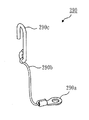
図15は図5で示す吊りひも290の傾斜図である。
図16は、本体部100に光源部200を取り付ける取付工程図である。
図17は、板バネ130の動作説明図である。
FIG. 1 is an oblique view of a
2 is an exploded perspective view of the
FIG. 3 is a perspective view of the
FIG. 4 is a perspective view of the
FIG. 5 is an exploded perspective view of the
6A is an enlarged view of a portion A of the
FIG. 7 is a side view of the
FIG. 8 is an oblique view of the
FIG. 9 is an enlarged view of a portion A of the
FIG. 10 is an enlarged view of a portion B of the
FIG. 11 is an oblique view of the disengaging
FIG. 12 is an oblique view of the connection fitting 250 shown in FIG.
FIG. 13 is an oblique view of the
FIG. 14 is a side view of the
FIG. 15 is an oblique view of the
FIG. 16 is an attachment process diagram for attaching the
FIG. 17 is an operation explanatory view of the
本実施の形態1における照明器具の構成について説明を行なう。本実施の形態では、本発明に係わる照明器具の一例として天井などの被取付部(以下、被取付部は天井を例に説明するが天井に限定するものではない)に取り付けられる、逆富士形の照明器具について説明する。以下の説明において、便宜上、天井面側(被取付面側)を上面側とし、床面側(被取付面と反対側)を下面側として説明をおこなう。 The structure of the lighting fixture in the first embodiment will be described. In this embodiment, as an example of the lighting apparatus according to the present invention, a reverse fuji type that is mounted on a mounting portion such as a ceiling (hereinafter, the mounting portion will be described by taking a ceiling as an example but not limited to a ceiling) The lighting equipment of In the following description, for convenience, the ceiling surface side (mounting surface side) is referred to as the upper surface side, and the floor surface side (opposite to the mounting surface) is referred to as the lower surface side.
図1のように、照明器具1000は、天井に当接するように設置される本体部100と、本体部100に脱着可能に取り付けられる光源部200とを備えている。本体部100は、光源部200を本体部100に固定するための板バネ130と、外部から引き込まれた電源電線が接続される端子台120を備えている。照明器具1000では、長手形状の光源部200が長手形状の本体部100に対向して脱着可能に装着される。
As shown in FIG. 1, the
(本体部100)
図2、図3のように、本体部100は、長手方向に沿って略中央部に凹部111が形成されている。図6(b)で凹部111を説明する。凹部111は、取付部112、光源固定部113(113a,113b)、傾斜部114を備える。光源固定部113は、光源部200が挿入される光源挿入部113a(側板)と、光源挿入部113aの外周に配設され光源部200と当接する光源受部113bから構成されている。凹部111は、その底辺側に天井に当接する取付部112(図6(b)で底板に相当)が形成されている。開口部側には光源部200の一部が挿入され固定される光源固定部113(光源挿入部113a、光源受部113b)が形成されている。光源挿入部113aは、取付部112の両端から立ち上がる側板である。取付部112の先端には、後述のカバー当接部230bに押し圧される光源受部113bが形成されている。光源受部113bのそれぞれからは、傾斜部114が形成されている。また、図2のように、両端部は凹部111及び傾斜部114を覆うように蓋部115が取り付けられている。
(Body part 100)
As shown in FIG. 2 and FIG. 3, the
図3のように本体部100の取付部112は、板バネ130と端子台120が取り付けらえるとともに、商用電源からの電力供給を受けるための電源線を引き込む電源引込孔112aと、天井へ固定する為の固定孔112bとが形成されている。また図6(b)のように、光源部200の落下を防止する吊りひも290を引っ掛ける吊孔112cが形成された金具112c−1が取り付けられている。
As shown in FIG. 3, the mounting
(引掛金具116)
図6(b)のように、2つの蓋部115のうち、板バネ130が配置されない方には、内部側に、後述の線バネ280(押し圧具)の先端部である引掛摺動部280dが引っ掛けられる引掛金具116(引掛具)が取り付けられている。引掛金具116には引掛摺動部280dが引っ掛けられる略角形状の開口である引掛孔116aが形成されている。なお、本実施の形態1では蓋部115と引掛金具116は別体になっているものに関して説明しているが、一体に形成されていても良いとする。
(Holding fitting 116)
As shown in FIG. 6 (b), in the two
(光源部200)
図5のように、光源部200は、
(1)複数のLED212(図示しない)と、複数のLEDが実装されてる基板211とからなるLED基板210と、
(2)LED基板210が取り付けられる保持部220と、
(3)保持部220にLED基板210を覆うように取り付くとともに、LED基板210から照射される光を拡散制御するカバー部230と、
(4)カバー部230の長手方向のそれぞれの端部を覆う光源蓋部240と、
(5)板バネ130と連結する連結金具250(連結具)と、
(6)カバー部230が保持部220からはずれることを防止するはずれ止部260と、(7)LED基板210を点灯させる点灯装置270と、
(8)引掛金具116に差し込まれる線バネ280と、
(9)光源部200の落下防止の為の、吊りひも290を備えている。
(Light source unit 200)
As shown in FIG. 5, the
(1) an
(2) a
(3) A
(4) a
(5) A connection fitting 250 (connector) connected to the
(6) a
(8)
(9) A hanging
(LED基板210)
LED基板210は、複数のLED212と、複数のLEDを実装する基板211を有しており、照明器具1000の長手方向と略同等となるよう長尺に形成されている。また、LED212は基板211の長尺方向へ略均等に並ぶように配設されている。
(LED board 210)
The
(保持部220)
図5のように、保持部220は、
(1)LED基板210が取り付けられる保持正面部220aと、
(2)保持正面部220aの長手両側面から垂直に突き出す(起立する)保持側面部220bから構成されており、長尺状に形成されている。
(3)また、保持正面部220aのLED基板210が取り付けられる背面には、板バネ130と連結する連結金具250を取り付ける為の連結金具取付台220cが形成されている。
(4)また、長手方向端部の片方には線バネ280の端部が差し込まれて保持する引掛バネ保持部220dと、「L」形状に対になるよう形成され線バネ280の可動を制御する引掛バネ制御部220eが形成されている。
(Holding section 220)
As shown in FIG.
(1) a holding
(2) It is comprised from the holding |
(3) Further, on the back surface of the holding
(4) In addition, the hook
(カバー部230)
カバー部230は、図10のように、
(1)断面が保持部220の保持側面部220bに係り合いをするカバー爪部230aと、
(2)保持正面部220aと同レベルに位置し、保持正面部220aと反対方向に形成され、光源受部113bに押し当たるカバー当接部230b、
(3)カバー当接部230b端部からLED基板210を覆うよう略円弧形状に形成されたカバー拡散部230c(図2)
から構成されており、長尺状に形成されている。
(Cover part 230)
The
(1) A
(2) A
(3) A
And is formed in a long shape.
(光源蓋部240)
光源蓋部240(図4)は、カバー部230のカバー当接部230bとカバー拡散部230cと、保持部220の保持正面部220aから構成される断面に嵌まり込んで塞いでいる。
(Light source cover 240)
The light source cover 240 (FIG. 4) is fitted in and closed in a cross section constituted by the
(連結金具250)
連結金具250(図12)は、中央の断面が略L形状に形成されており、バネ挿入部250aや、金具固定部250bが形成されている。保持部220の連結金具取付台220cに固定される。
(Connection bracket 250)
The cross-section at the center of the connection fitting 250 (FIG. 12) is substantially L-shaped, and a
(バネ挿入部250a)
バネ挿入部250aは、板バネ130を挿入する為に開口したバネ挿入孔250a−1と、バネ挿入孔250a−1から金具固定部250b方向の箇所が内側に曲げられたバネ受部250a−2と、はずれ止部260を固定する為のはずれ止受部250a−3を有している。
(
The
(金具固定部250b)
金具固定部250bは、連結金具取付台220cに当接して固定される。
(Metal fitting fixing
The metal
(はずれ止部260)
はずれ止部260(図11)は、図9のように保持部220とカバー部230の係合いが外れるのを防止する。また、図9のように、はずれ止部260は、保持部220と当接する当接部260aと、保持側面部220bとカバー爪部230aを覆うように嵌めこまれる係合カバー部260bを有している。
(Stop part 260)
The anti-disengagement portion 260 (FIG. 11) prevents the disengagement of the holding
(点灯装置270)
点灯装置270(図4)は、端子台120を介して商用電力からの電力をLED基板210に供給しLED基板210を点灯させるものであり、略直方体形状をした点灯装置本体部270aと、端子台120と連結する為の電源ケーブル270b及び連結コネクタ270cから構成されている。
(Lighting device 270)
The lighting device 270 (FIG. 4) supplies power from the commercial power to the
(線バネ280)
線バネ280(図13、図14)は、本体部100に設けられた引掛金具116の引掛孔116aに差し込まれる。線バネ280は、ステンレス材料や、バネ鋼板など弾性を有した線材を略四角形状に形成されたものである。
(Wire spring 280)
The wire spring 280 (FIGS. 13 and 14) is inserted into the hooking
線バネ280は、
(1)線材の両端であり、引掛バネ保持部220dに差し込まれる差込部280aと、
(2)引掛バネ保持部220dのL形状の内側に保持される保持部280bと、
(3)引掛孔116aに差し込まれたのちに、弾性力により引掛金具116を保持部220に押圧する押圧部280cとから構成されている。
なお、押圧部280cの先端は斜め上方向へ曲げられており、引掛孔116aの縁116a−1(図6(b))を摺動する引掛摺動部280dが形成されている。
(1) plug-in
(2) a holding
(3) It is comprised from the
The tip end of the
(吊りひも290)
光源部200を本体部100に取り付ける際には、吊りひも290(図15)を、本体部100の吊孔112cに引っ掛けた後に、光源部200を本体部100に取り付ける。これにより、光源部200の落下を防止する。吊りひも290は、
(1)光源部200の保持部220に取り付けられる連結部290aと、
(2)ひもなど柔軟性にすぐれ張力を有した張力部290bと、
(3)吊孔112cに引っ掛けられる略「J」形状をしたフック部290cから構成されている。
なお、本実施の形態1では連結部290aは点灯装置270とあわせてボルト及びナットにて固定される「O」形状のものを図示しているが、略「U」形状であり挟み込むようなものでも良く、連結部290aを用いず張力部290b自体を結んだものでもよい。
(Slingling strap 290)
When attaching the
(1) A connecting
(2) a
(3) It is comprised from the
In the first embodiment, the connecting
(板バネ130)
板バネ130(図7、図8)は、ステンレス材料や、バネ鋼板などの弾性材料で形成された、長手形状の板バネである。板バネ130は図7のように、第1平坦部L1(平坦部)、第1曲げ部M1、第2平坦部L2、第2曲げ部M2、第3平坦部L3、第3曲げ部M3、第4平坦部L4、第4曲げ部M4、円弧部E、屈曲部Kを備える。また第1曲げ部M1、第2平坦部L2、第2曲げ部M2、第3平坦部L3、第3曲げ部M3(突起部)、第4平坦部L4、第4曲げ部M4、円弧部E、屈曲部Kは、円弧形状部を構成する。
(1)第1平坦部L1(固定部)は、長手形状の一方の端部から長手方向に向かう。第1平坦部L1はネジ117で取付部112に固定される。
(2)第1曲げ部M1は、第1平坦部L1の終わりに、第1曲げ半径R1で形成される。(3)第2平坦部L2は、第1曲げ半径R1で第1角度θ1に曲げられて第1平坦部L1から立ち上がる。第2平坦部L2は、可動の軸になる(図16)。
(4)第2曲げ部M2は、第2平坦部L2の終わりに、第1曲げ半径R1と反対向きに第2曲げ半径R2で形成される。
(5)第3平坦部L3は、第2曲げ半径R2で鋭角の第2角度θ2に曲げられて延びる。(6)第3曲げ部M3は、第3平坦部L3の終わりに、第2曲げ半径R2と反対向きに第3曲げ半径R3で形成される。第3曲げ部M3は、光源部200が本体部100に装着完了となる直前に連結金具250のバネ受部250a−2に当たることで、円弧部Eの摺動を制御する。
(7)第4平坦部L4は、第3曲げ半径R3で鋭角の第3角度θ3に曲げられて延びる。(8)第4曲げ部M4は、第4平坦部L4の終わりに、第3曲げ半径R3と反対向きに第4曲げ半径R4で形成される。
(9)円弧部Eは、第4曲げ半径R4で鈍角の第4角度θ4に曲げられて第1平坦部L1の向かう長手方向に延びると共に第2平坦部L2の立ち上がる方向に凸となる円弧形状の部分である。円弧部Eは、連結金具250のバネ挿入孔250a−1の縁と当接して摺動する摺動部である。
(10)屈曲部K(引っ掛け部)は、円弧部Eの端部が屈曲されたものであり、連結金具250のバネ挿入孔250a−1の縁に引っ掛けられる(図16(b))。
(Leaf spring 130)
The leaf spring 130 (FIGS. 7 and 8) is a longitudinal leaf spring formed of a stainless steel material or an elastic material such as a spring steel plate. As shown in FIG. 7, the
(1) The first flat portion L1 (fixed portion) extends in the longitudinal direction from one end of the longitudinal shape. The first flat portion L1 is fixed to the mounting
(2) The first bent portion M1 is formed at the end of the first flat portion L1 with a first bending radius R1. (3) The second flat portion L2 is bent at the first bending radius R1 to the first angle θ1 and rises from the first flat portion L1. The second flat portion L2 is a movable axis (FIG. 16).
(4) The second bent portion M2 is formed at the end of the second flat portion L2 with a second bending radius R2 opposite to the first bending radius R1.
(5) The third flat portion L3 is bent at a second bending radius R2 and extended at an acute second angle θ2. (6) The third bent portion M3 is formed at the end of the third flat portion L3 with the third bending radius R3 opposite to the second bending radius R2. The third bending portion M3 controls the sliding of the arc portion E by striking the
(7) The fourth flat portion L4 is bent at a third bending radius R3 and extends at an acute third angle θ3. (8) The fourth bent portion M4 is formed at the end of the fourth flat portion L4 with the fourth bending radius R4 in the direction opposite to the third bending radius R3.
(9) The arc portion E is bent at a fourth bending radius R4 at an obtuse fourth angle θ4, extends in the longitudinal direction toward the first flat portion L1, and is convex in the rising direction of the second flat portion L2. Part of The arc portion E is a sliding portion that slides in contact with the edge of the
(10) The bent portion K (hook portion) is obtained by bending the end of the arc portion E, and is hooked on the edge of the
第2平坦部L2は、板バネ130が光源部200を取り付けするときの弾性作用の軸部である。
The second flat portion L2 is a shaft portion of elastic action when the
第4曲げ部M4の内側箇所M4−1は、板バネ130が光源部200を保持したときに、連結金具250のバネ挿入孔250a−1の縁に当接する。
The inner portion M4-1 of the fourth bent portion M4 abuts on the edge of the
(端子台120)
端子台120(図3)は、商用電源から供給される電力を光源部200へ供給する。
(Terminal block 120)
The terminal block 120 (FIG. 3) supplies the
次に、光源部200の本体部100への取付工程について説明する。図16は本実施の形態1における光源部200の本体部100への取付工程図である。図16のうち、(a)は、光源部200が本体部100に取り付けられる前の状態である。(b)は、作業者が、光源部200の線バネ280を本体部100の引掛金具116の引掛孔116aに差し込み、かつ、板バネ130の屈曲部K(引っ掛け部)を連結金具250のバネ挿入孔250a−1の縁に引っ掛けた状態である。(c)は、作業者が、引掛孔116aに差し込んだ線バネ280を回転の中心として、光源部200を(b)の状態から回転させた状態を示す。このとき板バネ130は連結金具250のバネ挿入孔250a−1の縁を摺動する。(d)は、本体部100に光源部200が取り付けられた状態である。
Next, a process of attaching the
((a)の状態)
図16の(a)では、光源部200と本体部100は別々の状態である。また、本体部100では、本体部100の引掛孔116a(縁116a−1)と光源受部113bとの間の距離B(図6(b))が、光源部200の保持部220の上面と線バネ280の引掛摺動部280dとの距離Aより大きくなるように形成されている。これについては後述する。
(State of (a))
In (a) of FIG. 16, the
((b)の状態)
次に図16の(b)では、作業者が、光源部200の線バネ280を本体部100の引掛金具116の引掛孔116aに差し込んだ状態であり、板バネ130の屈曲部Kを連結金具250のバネ挿入孔250a−1の縁に引っ掛けた状態である。線バネ280では、先端の引掛摺動部280dが引掛孔116aの縁116a−1上に当接しており、距離Bが距離Aより広い為(B>A)、押圧部280cが引掛孔116aの縁116a−1を押圧している状態である。なお距離Aは図5の保持正面部220aの上面から線バネ280の引掛摺動部280dの上方向の端部280d−1までの距離である(図14)。距離Bは、図6(b),図16(d)のように本体部100に光源部200が装着されたときの、保持正面部220aの上面(つまり、光源受部113b)から、引掛孔116aの縁116a−1までの距離である。
(State of (b))
Next, in FIG. 16B, the worker inserts the
板バネ130は、第2平坦部L2を取付部112に対する回転運動の回転中心として、円弧部Eが取付部112に対して垂直になるように弾性変形しながら回動する。また、板バネ130の屈曲部Kは、光源部200の連結金具250のバネ挿入孔250a−1の縁に引っ掛けられている。
The
なお、図16の(b)状態にて、吊りひも290のフック部290cは、本体部100の吊孔112cに引っ掛けられる。また、作業者は、本体部100の端子台コネクタ120aと光源部200の連結コネクタ270cを連結する。(なお、吊りひも290のフック部290cを吊孔112cに引っ掛けてから線バネ280を引掛孔116aに挿入し、板バネ130をバネ挿入孔250a−1に挿入する手順としてもよい)
In the state shown in FIG. 16 (b), the
((c)の状態)
次に、図16の(c)は、作業者が、引掛孔116aに差し込んだ線バネ280を回転の中心として、光源部200を(b)の状態から回転させた状態を示す。板バネ130の円弧部Eの本体部100側に位置する面が、バネ挿入孔250a−1の孔縁上をバネ復元力により摺動する。
(State of (c))
Next, (c) of FIG. 16 shows a state where the worker rotates the
板バネ130は円弧部Eが連結金具250のバネ挿入孔250a−1の縁を摺動する。他方の線バネ280は、作業者が線バネ280を中心として光源部200を回転させる際、線バネ280では、引掛摺動部280dが引掛孔116aの縁116a−1上を摺動しながら引掛孔116aに挿し込まれる。作業者は、さらに光源部200を回転させながら光源部200の右側を本体部100方向へ引き上げ、光源部200の保持側面部220bおよび、カバー爪部230aを本体部100へ挿入する。このとき板バネ130は円弧部Eがバネ挿入孔250a−1の上側の縁を摺動する。
In the
なお、線バネ280は距離Aが距離Bより狭い為、押圧部280cは弾性により変形しながら挿入されるとともに、引掛孔116aおよび光源固定部113を線バネ280と光源蓋部240で押圧し把持している。
The
((d)の状態)
次に、図16の(d)において、作業者が、本本体部100の光源受部113bと光源部200のカバー当接部230bが当接するように光源部200を本体部100へ押し込むと、板バネ130の第3曲げ部が連結金具250のバネ受部250a−2と当接し、光源部200は本体部100に取り付けられる。このとき板バネ130は、光源部200の装着状態が完了する直前では、第3曲げ部M3がバネ受部250a−2と当接し、円弧部Eの摺動が抑制される。そして作業者が光源部200の本体部100への差し込みを完了(光源部200の装着完了)すると、板バネ130の第4曲げ部M4の内側箇所M4−1が、連結金具250のバネ挿入孔250a−1の上側の縁と押し合う状態で、この縁に対して位置決めされる。このとき、板バネ130が内側箇所M4−1(図17)でバネ挿入孔250a−1の縁を支持する際のバネ定数は、図16の(b)において屈曲部Kで光源部200を支持する際のバネ定数に対して著しく大きい。これは、板バネ130では第1平坦部L1(固定)が本体部100に固定されるので、第1平坦部L1を固定端とする片持ち梁として大まかに見積もることができる。板バネ130では、ほとんど弾性変形しない第1曲げ部M1と第4曲げ部M4との直線距離(スパン)は、第1曲げ部M1と屈曲部Kとの距離(スパン)の、例えば1/5〜1/6程度である。片持ち梁ではスパンはバネ定数に3乗で影響する。よって、第4曲げ部M4におけるバネ定数は、1/5であれば屈曲部Kにおけるバネ定数の125倍であり、1/6であれば屈曲部Kにおけるバネ定数の216倍である。このため、作業者が光源部200を本体部100への差し込みを完了すると、板バネ130の第4曲げ部M4の内側箇所M4−1が、連結金具250のバネ挿入孔250a−1の上側の縁を支持できる。つまり第4曲げ部M4の内側箇所M4−1で、光源部200の自重を支持することができる。
この(d)の状態で線バネ280の下面280d−1−1(図14)は、図16(d)の矢印の方向に戻ろうとする復元力によって、縁116a−1を押圧している。
(State of (d))
Next, in (d) of FIG. 16, when the worker pushes the
In the state of (d), the
(取り外し方法)
次に、光源部200を本体部100から取り外す方法について説明する。光源部200の取り外し方法は、取り付け方法の逆の手順になる。
(1)まず、作業者は図16の(d)の光源部200が本体部100が取り付けられた状態から、板バネ130が設置されている側を下方向に引き下げる。
(2)次に、作業者は光源部200を図16の(b)の状態まで引き下げたら、端子台コネクタ120aと連結コネクタ270cとの連結を解徐し、吊りひも290のフック部290cを本体部100の吊孔112cからはずし、その後、板バネ130の屈曲部Kを連結金具250のバネ挿入孔250a−1から外す。(なお、吊りひも290のフック部290cは線バネ280を引掛金具116から外した後に吊孔112cから外すようにしてもよい)
(3)最後に、作業者は光源部200を引掛金具116から挿し込みした方向と反対方向へ線バネ280を引き抜き、光源部200を本体部100から取り外す。
(How to remove)
Next, a method of removing the
(1) First, the operator pulls down the side on which the
(2) Next, when the operator pulls down the
(3) Finally, the operator withdraws the
次に、取付時における、板バネ130の弾性作用(作用効果)に関して説明をする。図17は、本実施の形態1の取付時における、板バネ130の第2平坦部L2(可動軸)の周辺の拡大図である。図17において、点線は弾性変形していない状態(図16の(a)の状態)の板バネ130(板バネ130aとする)を示し、実線は内側箇所M4−1で光源部200を保持している弾性変形状態(図16の(d)の状態)の板バネ130(板バネ130bとする)を示している。
Next, the elastic action (action and effect) of the
図17において、板バネ130b(実線)では、内側箇所M4−1(黒丸で示した)が、板バネ130a(点線)の内側箇所M4−1相当箇所(板バネ130b(実線)で内側箇所M4−1に印をつけて板バネ130a(点線)の状態に戻したときの印の位置)と比較すると、以下の様である。つまり板バネ130b(実線)は、第1平坦部L1の方向へ水平に寸法A、下側方向に寸法Bだけ弾性変形した状態で、光源部200(連結金具250)を保持している。
In FIG. 17, in the
(板バネ130のへたりと弾性力との関係)
板バネ130は図16の(b)のように使用される。よってへたりが生じると図6における第2角度θ3が大きくなる方向に影響するが、この影響は図17において寸法Aが増加する方向に働き、結果としてへたりが生じた際の板バネ130が光源部200(連結金具250)を支持する弾性力の低下を抑制できる。このように、板バネ130の形状的特徴によって、板バネ130に劣化(へたり)が発生しても、弾性力の低下をもたらすことなく(へたりにより、むしろ弾性力(たわみ)が増加する)、光源部200を保持できる効果を有する。なお、連結金具250は板バネ130と連結するものであり、寸法A、寸法Bがマイナスにならないものであれば、本実施の形態1以外の形状のものでも良い。
(Relationship between
The
本実施の形態は、光源部200に設けられ本体部100の引掛金具に挿入されるとともに本体部100の一部を把持する線バネ280と、本体部100に設けられ光源部200に設けられた連結金具250を摺動し光源部200を引き上げる板バネ130により、本体部100と光源部200が確実に、かつ簡単に連結される連結機構、及びその連結機構を備えた照明器具を提供することができる。
In the present embodiment, a
本実施の形態は、引掛金具116及び連結金具250は、線バネ280及び板バネ130が弾性変形した状態で連結するように配設されており、光源部200は線バネ280及び板バネ130の復元力により保持される連結機構、及びその連結機構を備えた照明器具を提供することができる。
In the present embodiment, the hooking fitting 116 and the connecting fitting 250 are disposed such that the
また、本実施の形態では、逆富士形の照明器具1000について説明をしたが、本体部100と光源部200が一体になっておらず光源部200を本体部100に取り付ける照明器具であれば、埋込型、直付け型でもよく、天井スクエア型など略正方形状をしたものでもよい。
Further, in the present embodiment, the inverted Fuji-
なお、本実施の形態では本体部100側に板バネ130と引掛金具116を設け、光源部200側に連結金具250と線バネ280を設ける仕様について説明を行なったが、本体部側が連結金具と引掛バネを備え、光源部がバネ部と引掛金具を備える仕様でもよく、どちらか一方がバネ部を備えもう一方が金具部を備えている仕様でもよい。
In the present embodiment, the
1000 照明器具、100 本体部、111 凹部、112 取付部、112a 電源引込孔、112b 固定孔、112c 吊孔、113 光源固定部、113a 光源挿入部、113b 光源受部、114 傾斜部、115 蓋部、116 引掛金具、116a 引掛孔、117 ネジ、120 端子台、120a 端子台コネクタ、130 板バネ、200 光源部、210 LED基板、211 基板、212 LED、220 保持部、220a 保持正面部、220b 保持側面部、220c 連結金具取付台、220d 引掛バネ保持部、220e 引掛バネ制御部、230 カバー部、230a カバー爪部、230b カバー当接部、230c カバー拡散部、240 光源蓋部、250
連結金具、250a バネ挿入部、250a−1 バネ挿入孔、250a−2 バネ受部、250a−3 はずれ止受部、250b 金具固定部、260 はずれ止部、260a 当接部、260b 係合カバー部、270 点灯装置、270a 点灯装置本体部、270b 電源ケーブル、270c 連結コネクタ、280 線バネ、280a 差込部、280b 保持部、280c 押圧部、280d 引掛摺動部、290 吊りひも、290a 連結部、290b 張力部、290c フック部、L1 第1平坦部、L2 第2平坦部、L3 第3平坦部、L4 第4平坦部、M1 第1曲げ部、M2 第2曲げ部、M3 第3曲げ部、M4 第4曲げ部、E 円弧部、K 屈曲部。
DESCRIPTION OF
Connection fitting, 250a spring insertion portion, 250a-1 spring insertion hole, 250a-2 spring reception portion, 250a-3 displacement prevention portion, 250b bracket fixing portion, 260 displacement prevention portion, 260a abutment portion, 260b engagement cover portion , 270 lighting device, 270a lighting device body, 270b power cable, 270c connection connector, 280 wire spring, 280a insertion portion, 280b holding portion, 280c pressing portion, 280d hook sliding portion, 290 hanging strap, 290a connecting portion, 290b tension portion, 290c hook portion, L1 first flat portion, L2 second flat portion, L3 third flat portion, L4 fourth flat portion, M1 first bent portion, M2 second bent portion, M3 third bent portion, M4 4th bend, E arc, K bend.
Claims (2)
前記光源部の一部によって通過されている開口を形成する長手形状の本体部と、
前記光源部の長手方向の前記フレームの一端の側に設けられ、前記フレームの一端から前記フレームの他端に向かう方向であるフレーム他端方向に向かって、順に、摺動部と、前記摺動部に接続する押圧部と、前記押圧部に接続すると共に前記フレームの一端の側で前記フレームに保持される保持部とを有するバネと、
前記本体部の前記開口の前記フレームの一端の側の縁に設けられた引掛金具と、
を備え、
前記バネは、
前記光源部の一端の側を前記本体部の開口に差し込む際に前記摺動部が前記引掛金具に当接し、
前記摺動部は、
前記引掛金具を摺動することで、前記引掛金具に当接する当接箇所を前記押圧部に移し、かつ、前記押圧部が前記フレームから離れて前記押圧部の弾性力が増加した状態にさせて前記押圧部に前記引掛金具を押圧させる照明器具。 A light source unit which has a longitudinal shape and a frame to which the light source is attached;
A longitudinally-shaped main body portion that forms an opening that is passed by a portion of the light source portion;
Wherein provided on one end side of the longitudinal direction of the frame of the light source, toward the frame and the other end direction from one end a toward the other end of said frame of said frame, in order, a sliding portion, the sliding A spring having a pressing part connected to the part, and a holding part connected to the pressing part and held by the frame on one end side of the frame ;
A hook provided at an edge of the opening of the main body on one end side of the frame ;
Equipped with
The spring is
When the one end side of the light source portion is inserted into the opening of the main body portion, the sliding portion abuts on the hook fitting,
The sliding portion,
By sliding the front Symbol hook bracket abuts the contact portion to the hook bracket transferred to the pressing section and is in a state where the pressing portion elastic force of the pressing portion away from said frame has increased The lighting fixture which makes the said pressing part press the said hook metal fitting .
前記フレームに設けられた状態で、前記光源部の前記一端に向うに従って前記フレームから離れるように傾斜している請求項1に記載の照明器具。 The sliding portion is
The luminaire according to claim 1, wherein the luminaire is provided so as to be separated from the frame as it goes to the one end of the light source unit in a state of being provided to the frame.
Priority Applications (1)
| Application Number | Priority Date | Filing Date | Title |
|---|---|---|---|
| JP2017234228A JP6509313B2 (en) | 2017-12-06 | 2017-12-06 | lighting equipment |
Applications Claiming Priority (1)
| Application Number | Priority Date | Filing Date | Title |
|---|---|---|---|
| JP2017234228A JP6509313B2 (en) | 2017-12-06 | 2017-12-06 | lighting equipment |
Related Parent Applications (1)
| Application Number | Title | Priority Date | Filing Date |
|---|---|---|---|
| JP2014037266A Division JP6258072B2 (en) | 2014-02-27 | 2014-02-27 | lighting equipment |
Publications (3)
| Publication Number | Publication Date |
|---|---|
| JP2018037422A JP2018037422A (en) | 2018-03-08 |
| JP2018037422A5 JP2018037422A5 (en) | 2018-09-13 |
| JP6509313B2 true JP6509313B2 (en) | 2019-05-08 |
Family
ID=61567513
Family Applications (1)
| Application Number | Title | Priority Date | Filing Date |
|---|---|---|---|
| JP2017234228A Active JP6509313B2 (en) | 2017-12-06 | 2017-12-06 | lighting equipment |
Country Status (1)
| Country | Link |
|---|---|
| JP (1) | JP6509313B2 (en) |
Families Citing this family (1)
| Publication number | Priority date | Publication date | Assignee | Title |
|---|---|---|---|---|
| JP7188099B2 (en) * | 2019-01-15 | 2022-12-13 | 三菱電機株式会社 | lighting equipment |
Family Cites Families (4)
| Publication number | Priority date | Publication date | Assignee | Title |
|---|---|---|---|---|
| JP4375141B2 (en) * | 2004-06-24 | 2009-12-02 | パナソニック電工株式会社 | lighting equipment |
| JP5171661B2 (en) * | 2009-01-20 | 2013-03-27 | シャープ株式会社 | LED lighting fixtures |
| JP5834219B2 (en) * | 2011-03-04 | 2015-12-16 | パナソニックIpマネジメント株式会社 | Lighting device |
| JP5885985B2 (en) * | 2011-10-03 | 2016-03-16 | シャープ株式会社 | Lighting device |
-
2017
- 2017-12-06 JP JP2017234228A patent/JP6509313B2/en active Active
Also Published As
| Publication number | Publication date |
|---|---|
| JP2018037422A (en) | 2018-03-08 |
Similar Documents
| Publication | Publication Date | Title |
|---|---|---|
| JP6258072B2 (en) | lighting equipment | |
| JP5954665B2 (en) | lighting equipment | |
| JP6271296B2 (en) | lighting equipment | |
| JP5623209B2 (en) | Lighting apparatus and method of assembling the lighting apparatus | |
| KR20160051352A (en) | Illumination module with one touch combination structure | |
| JP6509313B2 (en) | lighting equipment | |
| JP6376773B2 (en) | Spring for lighting device and lighting device | |
| JP6258071B2 (en) | Lighting device | |
| JP6198890B2 (en) | Mounting spring for light fixture and light source unit | |
| US7824081B2 (en) | Helicoidal system for recessed light fixture assembly | |
| JP6230657B2 (en) | Lighting fixture and mounting spring for lighting fixture | |
| JP6192772B2 (en) | Lighting apparatus and method of attaching the lighting apparatus | |
| JP6293204B2 (en) | lighting equipment | |
| JP6095831B2 (en) | lighting equipment | |
| WO2015129637A1 (en) | Spring for illumination device, illumination device, and illumination apparatus | |
| JP6448752B2 (en) | lighting equipment | |
| JP6293203B2 (en) | lighting equipment | |
| JP6017082B2 (en) | Mounting spring for light fixture and light source unit | |
| JP6626077B2 (en) | Lighting equipment | |
| JP6799559B2 (en) | Lighting device springs and lighting devices | |
| JP6626058B2 (en) | lighting equipment | |
| JP6665152B2 (en) | lighting equipment | |
| KR20230105272A (en) | Elastic mounting device and equipment mounting devices using the same | |
| KR20240053030A (en) | Fixing and taking away device of fixing objects |
Legal Events
| Date | Code | Title | Description |
|---|---|---|---|
| A621 | Written request for application examination |
Free format text: JAPANESE INTERMEDIATE CODE: A621 Effective date: 20171226 |
|
| A521 | Request for written amendment filed |
Free format text: JAPANESE INTERMEDIATE CODE: A523 Effective date: 20180801 |
|
| A977 | Report on retrieval |
Free format text: JAPANESE INTERMEDIATE CODE: A971007 Effective date: 20181031 |
|
| A131 | Notification of reasons for refusal |
Free format text: JAPANESE INTERMEDIATE CODE: A131 Effective date: 20181106 |
|
| A521 | Request for written amendment filed |
Free format text: JAPANESE INTERMEDIATE CODE: A523 Effective date: 20181214 |
|
| TRDD | Decision of grant or rejection written | ||
| A01 | Written decision to grant a patent or to grant a registration (utility model) |
Free format text: JAPANESE INTERMEDIATE CODE: A01 Effective date: 20190305 |
|
| A61 | First payment of annual fees (during grant procedure) |
Free format text: JAPANESE INTERMEDIATE CODE: A61 Effective date: 20190402 |
|
| R150 | Certificate of patent or registration of utility model |
Ref document number: 6509313 Country of ref document: JP Free format text: JAPANESE INTERMEDIATE CODE: R150 |
|
| R250 | Receipt of annual fees |
Free format text: JAPANESE INTERMEDIATE CODE: R250 |
|
| R250 | Receipt of annual fees |
Free format text: JAPANESE INTERMEDIATE CODE: R250 |
|
| R250 | Receipt of annual fees |
Free format text: JAPANESE INTERMEDIATE CODE: R250 |