JP6258071B2 - Lighting device - Google Patents
Lighting device Download PDFInfo
- Publication number
- JP6258071B2 JP6258071B2 JP2014037095A JP2014037095A JP6258071B2 JP 6258071 B2 JP6258071 B2 JP 6258071B2 JP 2014037095 A JP2014037095 A JP 2014037095A JP 2014037095 A JP2014037095 A JP 2014037095A JP 6258071 B2 JP6258071 B2 JP 6258071B2
- Authority
- JP
- Japan
- Prior art keywords
- light source
- spring
- main body
- unit
- attached
- Prior art date
- Legal status (The legal status is an assumption and is not a legal conclusion. Google has not performed a legal analysis and makes no representation as to the accuracy of the status listed.)
- Active
Links
- 238000006073 displacement reaction Methods 0.000 claims description 2
- 230000002093 peripheral effect Effects 0.000 claims 3
- 238000005452 bending Methods 0.000 description 25
- 238000003780 insertion Methods 0.000 description 19
- 230000037431 insertion Effects 0.000 description 19
- 239000002184 metal Substances 0.000 description 13
- 210000000078 claw Anatomy 0.000 description 11
- 238000000034 method Methods 0.000 description 6
- 230000007246 mechanism Effects 0.000 description 5
- 230000009471 action Effects 0.000 description 4
- 238000009792 diffusion process Methods 0.000 description 4
- 238000010586 diagram Methods 0.000 description 3
- 235000010724 Wisteria floribunda Nutrition 0.000 description 2
- 230000001154 acute effect Effects 0.000 description 2
- 230000008878 coupling Effects 0.000 description 2
- 238000010168 coupling process Methods 0.000 description 2
- 238000005859 coupling reaction Methods 0.000 description 2
- 230000000694 effects Effects 0.000 description 2
- 230000002265 prevention Effects 0.000 description 2
- 239000000758 substrate Substances 0.000 description 2
- 229910000639 Spring steel Inorganic materials 0.000 description 1
- 230000008901 benefit Effects 0.000 description 1
- 238000010276 construction Methods 0.000 description 1
- 239000013013 elastic material Substances 0.000 description 1
- 238000005286 illumination Methods 0.000 description 1
- 238000009434 installation Methods 0.000 description 1
- 239000000463 material Substances 0.000 description 1
- 230000004048 modification Effects 0.000 description 1
- 238000012986 modification Methods 0.000 description 1
- 230000000630 rising effect Effects 0.000 description 1
- 238000007665 sagging Methods 0.000 description 1
- 229910001220 stainless steel Inorganic materials 0.000 description 1
- 239000010935 stainless steel Substances 0.000 description 1
- 230000001502 supplementing effect Effects 0.000 description 1
- 230000001629 suppression Effects 0.000 description 1
Images


Description
近年、蛍光灯用照明器具に変わって、LEDを光源とした照明器具が使用されている。LEDを使用する照明器具は、従来の蛍光灯用照明器具と同様に、天井などの被取付面に固定された本体部に、LEDが配置された光源部が脱着可能に固定されるものがある。 In recent years, lighting fixtures using LEDs as light sources have been used instead of fluorescent lighting fixtures. As in the case of conventional fluorescent lamp lighting fixtures, there are some lighting fixtures using LEDs in which a light source portion in which LEDs are arranged is detachably fixed to a main body portion fixed to a mounting surface such as a ceiling. .
光源部と本体部との取付方法には、光源部が、本体部に設けられた窪みに挿入されて取り付けられる照明器具であって、光源部の側面に設けられたバネ部材が弾性変形しながら窪みに挿入され、窪み内部に設けられ光源部を固定する金具と係合し、光源部と本体部が連結されるものがある(例えば、特許文献1)。
また、点灯装置を備えた光源部が本体部に取り付けられたものもあり、点灯装置を備えた光源部の側面全長に溝部が形成され、本体部には光源部溝部全長と係合する爪部が設けられており、側面全長で係合することで、光源部の重量負荷を分散化し、爪部の変形防止を行なっているものもある(例えば、特許文献2)。
The method of attaching the light source part and the main body part is a lighting fixture in which the light source part is inserted and attached to a recess provided in the main body part, and the spring member provided on the side surface of the light source part is elastically deformed. There is one that is inserted into a recess, engages with a metal fitting that is provided inside the recess and fixes the light source unit, and the light source unit and the main body unit are connected (for example, Patent Document 1).
In addition, there is a light source part provided with a lighting device attached to the main body part, a groove part is formed in the entire side surface of the light source part provided with the lighting device, and the claw part that engages with the light source part groove part full length in the main body part Is provided, and the weight load of the light source part is dispersed by engaging with the full length of the side surface to prevent deformation of the claw part (for example, Patent Document 2).
特許文献1の照明器具は複数のバネ部材により光源部と本体部が連結されており、複数のバネ部材を同時に対応する固定金具に差し込まないとバネ部に応力がかかり、バネ部の変形や照明器具の故障をもたらすおそれがある。
また、特許文献2の照明器具は、側面全長にて、溝部と爪部と嵌合している。その為、光源部を本体部から取り外すときは、嵌合した全長を同時に押圧し溝部と、爪部との嵌合状態の解徐を要し、専用の治具が必要となる。
In the lighting apparatus of
Moreover, the lighting fixture of
本発明では、光源部と本体部とが脱着可能な照明装置おいて、光源部と本体部が簡単に連結でき、光源部の取り付け作業の容易な照明装置の提供を目的とする。 An object of the present invention is to provide an illuminating device in which the light source unit and the main body can be easily connected in the illuminating device in which the light source and the main body are detachable, and the light source unit can be easily attached.
この発明の照明装置は、
光源部と本体部とを備え、前記光源部が前記本体部に対向して脱着可能に装着される照明装置において、
前記光源部と前記本体部とのどちらかに取り付けられる長手形状の板バネであるバネ部であって、長手方向に向かう平坦部と、前記平坦部の終わりから前記光源部と前記本体部とのうち取り付けられない方に向かって凸となる円弧形状の円弧形状部とを有し、前記平坦部で前記光源部と前記本体部とのどちらかに取り付けられるバネ部と、
前記光源部と前記本体部とのうち前記バネ部が取り付けられない方に取り付けられる連結部であって、前記円弧形状部を貫通させる開口が形成され、前記平坦部の終わり付近の前記円弧形状部である付近円弧形状部を、無負荷状態に対して変位させた状態で前記開口の周縁が前記付近円弧形状部と当接する連結部と
を備えたことを特徴とする。
The lighting device of the present invention is
In a lighting device comprising a light source part and a main body part, wherein the light source part is detachably mounted facing the main body part,
A spring part that is a longitudinal leaf spring attached to either the light source part or the main body part, and a flat part that extends in the longitudinal direction, and the light source part and the main body part from the end of the flat part A circular arc-shaped portion that is convex toward the side that cannot be attached, and a spring portion that is attached to either the light source portion or the main body portion at the flat portion;
The connecting part that is attached to the light source part and the main body part to which the spring part is not attached, and an opening that penetrates the arc-shaped part is formed, and the arc-shaped part near the end of the flat part The vicinity arc-shaped portion is a displacement portion that is displaced with respect to the no-load state, and includes a connecting portion in which the periphery of the opening abuts on the near-arc shape portion.
本発明によれば、光源部と本体部とが脱着可能な照明装置おいて、光源部と本体部が簡単に連結でき、光源部の取り付け作業の容易な照明装置を提供できる。 ADVANTAGE OF THE INVENTION According to this invention, in the illuminating device with which a light source part and a main-body part can be attached or detached, a light source part and a main-body part can be connected easily, and the illuminating device with which the attachment operation | work of a light source part is easy can be provided.
実施の形態1.
図1〜図18を参照して実施の形態1の照明器具1000(照明装置)の構成を説明する。実施の形態1では、本発明に係る照明器具の一例として、天井などの被取付部(以下、被取付部として天井を例に説明するが天井に限定されない)に取り付けられる、逆富士形の照明器具1000について説明する。以下の説明において、便宜上、天井面側(被取付面側)を上面側とし、床面側(被取付面と反対側)を下面側として説明をおこなう。
With reference to FIGS. 1-18, the structure of the lighting fixture 1000 (illuminating device) of
図1は照明器具1000の斜視図である。図2は図1に示す照明器具1000の分解斜視図である。図3は、図1に示す本体部100の斜視図である。図4は図1に光源部200の斜視図である。
FIG. 1 is a perspective view of a
(照明器具1000の構成)
図1、図2のように、照明器具1000(照明装置)は、天井(被取付部)に当接するように設置される本体部100と、本体部100に脱着可能に取り付けられる光源部200から構成される。光源部200は本体部100に対向するように脱着可能に取り付けられる。
(Configuration of lighting apparatus 1000)
As shown in FIGS. 1 and 2, a lighting fixture 1000 (lighting device) includes a
(本体部100)
図2のように、本体部100は、照明器具1000の外部から引き込まれた電源電線が接続される端子台120と、光源部200を本体部100に取り付ける(固定する)ためのバネ部130(照明装置用バネ)を備えている。
(Main body 100)
As shown in FIG. 2, the
(凹部111、取付部112、光源固定部113、傾斜部114、蓋部115)
図3のように、本体部100は、長手方向に沿って略中央部に凹部111が形成されている。図14は凹部111を示すための図であり、図3の断面A−Aである。図5、図14のように、凹部111の底辺側には天井に当接する取付部112が形成されている。開口部側(図14)には光源部200の一部が挿入されて固定される、光源固定部113(図3)が形成されている。光源固定部113は、光源部200が挿入される光源挿入部113aと、光源部200を受ける光源受部113bから構成されている。光源挿入部113aは図14に示すように凹部111の両方の壁をなす縦板である。光源受部113bは図14に示すように、光源挿入部113aの上端であり傾斜部114の始まる箇所である。光源受部113b(図14)は、光源挿入部113aの上端において光源部200(カバー部230)と当接することで光源部200を受ける。具体的には光源受部113bはカバー当接部230b(図16)と当接して光源部200(カバー部230)を受ける。また図2、図14のように、逆富士形の斜面に相当する傾斜部114が光源受部113bから形成されている。図2に示すように、本体部100の両端には、凹部111端部及び傾斜部114端部を覆うように、蓋部115が取り付けられる。
(
As shown in FIG. 3, the
(電源引込孔112a、固定孔112b)
図3のように、本体部100の取付部112には、バネ部130、端子台120が取り付く。また、取付部112には、商用電源供給用の電源線を引き込む電源引込孔112aや、天井へ固定する為の固定孔112bが形成されている。
(
As shown in FIG. 3, the
(光源部200)
図4のように、光源部200は、LEDユニット210(図4には示していない)、保持部220、カバー部230、光源蓋部240、連結金具250(連結部)、はずれ止部260、点灯装置270を備えている。
(1)LEDユニット210(図15,図16)は、複数のLED(図示していない)と、この複数のLEDが実装される基板とからなる。
(2)保持部220(後述する)は、LEDユニット210が取り付けられる。図15は図4のB−B断面である。図15に示すように保持部220は底板に相当する保持正面部220aと、保持正面部220aの両側の側板に相当する保持側面部220bからなる。(3)図15のように、カバー部230は、保持部220にLEDユニット210を覆うように取り付くとともに、LEDユニット210から照射される光を拡散制御する。
(4)光源蓋部240(図4、図17)は、カバー部230の端部を覆う蓋である。
(5)連結金具250は、バネ部130と連結する。
(6)はずれ止部260(図10)は、カバー部230が保持部220から外れることを防止する、カバー部230の外れ止めである。
(7)点灯装置270(図4)は、LEDユニット210を点灯させる装置である。
(Light source unit 200)
As shown in FIG. 4, the
(1) The LED unit 210 (FIGS. 15 and 16) includes a plurality of LEDs (not shown) and a substrate on which the plurality of LEDs are mounted.
(2) The
(4) The light source lid portion 240 (FIGS. 4 and 17) is a lid that covers the end portion of the
(5) The connection fitting 250 is connected to the
(6) The detachment preventing portion 260 (FIG. 10) is a detachment prevention of the
(7) The lighting device 270 (FIG. 4) is a device that lights the
LEDユニット210は、照明器具1000の長手方向と略同等となるように長尺になるように形成されている(図1)。また、LEDは基板に長尺方向へ並ぶように、一列あるいは複数列で配設されている。
The
保持部220(図8、図15)は、前述のように断面がLEDユニット210が取り付けられる保持正面部220a(図8)と、保持正面部220aの両端部から垂直に突出した保持側面部220b(図15)から構成されており、長尺状に形成されている。また、保持正面部220aのLEDユニット210が取り付けられる面の背面(上面側)には、バネ部130と連結する連結金具250(図9)を取り付ける為の、連結金具取付台220c(図4、図8)が形成されている。
The holding part 220 (FIGS. 8 and 15) includes a holding
(カバー部230)
カバー部230(図2、図15、図16)は、カバー爪部230a、カバー当接部230b、カバー拡散部230cを備える。
(1)カバー爪部230aは、図15、図16のように、保持側面部220bに係合して、保持側面部220bに取り付く。
(2)カバー当接部230bは、図15のように保持正面部220aと同レベル(上面方向でほぼ同じ高さ)に位置し、保持正面部220aから外側へ広がる。
(3)カバー拡散部230c(図15)は、カバー当接部230bの外側端部から略円弧形状をなすように形成されてLEDユニット210を覆う長尺状である。
(Cover 230)
The cover part 230 (FIGS. 2, 15, and 16) includes a
(1) The
(2) The
(3) The
(光源蓋部240、図4、図17)
光源蓋部240(図17)は、カバー部230のカバー当接部230b、カバー拡散部230c、保持正面部220aとから構成される端部(図16)に嵌まり込み、前記端部を塞いでいる。
(
The light source cover part 240 (FIG. 17) is fitted into an end part (FIG. 16) composed of the
(連結金具250)
連結金具250(図4、図8、図9)は、断面が略L形状(図12)に形成されている。連結金具250は、バネ挿入部250aと、金具固定部250bから形成されており、保持部220の連結金具取付台220c(図8、図12)に固定される。
(Connecting bracket 250)
The connecting metal fitting 250 (FIGS. 4, 8, and 9) has a substantially L-shaped cross section (FIG. 12). The connecting metal fitting 250 is formed of a
(バネ挿入部250a)
図9のように、バネ挿入部250aは、バネ部130を挿入する為に開口した、バネ挿入孔250a−1(開口)、バネ挿入孔250a−1から金具固定部250b方向の箇所が内側に曲げられたバネ受部250a−2、及び、はずれ止部260を固定する為のはずれ止受部250a−3を有している。
(
As shown in FIG. 9, the
(金具固定部250b)
金具固定部250b(図9)は、連結金具取付台220c(図12)に当接し固定されると共に、端部が外側(保持部220側)に曲げられたバネ摺動補助部250b−1が形成されている。
(Fitting fixing
The metal
(はずれ止部260)
はずれ止部260(図10)は、保持部220(保持側面部220b)とカバー部230との係合いが外れるのを防止する部材であり、嵌合部260aが連結金具250に嵌合することで連結金具250に固定されている。はずれ止部260は、連結金具250を覆うように嵌り合う嵌合部260aと、保持側面部220bとカバー爪部230aを覆うように嵌めこまれる係合カバー部260bを有している。はずれ止部260は、嵌合部260aのクリップ部261aが連結金具250のはずれ止受部250a−3を挟むことで、連結金具250に係合する。また、図15のように係合カバー部260bは、保持側面部220bとカバー爪部230aとを挟み込んで、保持側面部220bとカバー爪部230aとの係合が外れるのを防止する。
(Release stop part 260)
The detachment preventing portion 260 (FIG. 10) is a member that prevents the engagement between the holding portion 220 (holding
(点灯装置270)
点灯装置270(図4)は、端子台120(図3)を介して商用電力からの電力をLEDユニット210に供給し、LEDユニット210を点灯させる装置である。点灯装置270は略直方体形状をした点灯装置本体部270aと、端子台120と連結する電源コネクタ270bから構成されている。
(Lighting device 270)
The lighting device 270 (FIG. 4) is a device that supplies power from the commercial power to the
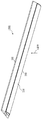
(バネ部130)
バネ部130(図3、図5〜図7)は、取付部112(図5)に、ネジ116により固定される。バネ部130は光源部200を固定する機能を有する(図11、図12で述べる)。
(Spring part 130)
The spring portion 130 (FIGS. 3 and 5 to 7) is fixed to the attachment portion 112 (FIG. 5) with a
バネ部130は、ステンレス材料や、バネ鋼板などの弾性材料で形成された、長手形状の板バネである。バネ部130(照明装置用バネ)は図6のように、第1平坦部L1(平坦部)、第1曲げ部M1、第2平坦部L2、第2曲げ部M2、第3平坦部L3、第3曲げ部M3、第4平坦部L4、第4曲げ部M4、円弧部E、屈曲部Kを備える。また第1曲げ部M1、第2平坦部L2、第2曲げ部M2、第3平坦部L3、第3曲げ部M3(突起部)、第4平坦部L4、第4曲げ部M4、円弧部E、屈曲部Kは、円弧形状部を構成する。
(1)第1平坦部L1(固定部)は、長手形状の一方の端部から長手方向に向かう。第1平坦部L1はネジ116(図5)で取付部112に固定される。
(2)第1曲げ部M1は、第1平坦部L1の終わりに、第1曲げ半径R1で形成される。(3)第2平坦部L2は、第1曲げ半径R1で第1角度θ1に曲げられて第1平坦部L1から立ち上がる。第2平坦部L2は、可動の軸になる(図11)。
(4)第2曲げ部M2は、第2平坦部L2の終わりに、第1曲げ半径R1と反対向きに第2曲げ半径R2で形成される。
(5)第3平坦部L3は、第2曲げ半径R2で鋭角の第2角度θ2に曲げられて延びる。(6)第3曲げ部M3は、第3平坦部L3の終わりに、第2曲げ半径R2と反対向きに第3曲げ半径R3で形成される。第3曲げ部M3は、光源部200が本体部100に装着完了となる直前に連結金具250のバネ受部250a−2に当たることで、円弧部Eの摺動を制御する。
(7)第4平坦部L4は、第3曲げ半径R3で鋭角の第3角度θ3に曲げられて延びる。(8)第4曲げ部M4は、第4平坦部L4の終わりに、第3曲げ半径R3と反対向きに第4曲げ半径R4で形成される。
(9)円弧部Eは、第4曲げ半径R4で鈍角の第4角度θ4に曲げられて第1平坦部L1の向かう長手方向に延びると共に第2平坦部L2の立ち上がる方向に凸となる円弧形状の部分である。円弧部Eは、連結金具250の開口縁部250a−1−1(図9)と当接して摺動する摺動部である。
(10)屈曲部K(引っ掛け部)は、円弧部Eの端部が屈曲されたものであり、連結金具250の開口縁部250a−1−1に引っ掛けられる(図11の(b))。
The
(1) The 1st flat part L1 (fixed part) goes to a longitudinal direction from one edge part of a longitudinal shape. The first flat portion L1 is fixed to the
(2) The first bending portion M1 is formed with the first bending radius R1 at the end of the first flat portion L1. (3) The second flat portion L2 is bent at the first angle θ1 with the first bending radius R1 and rises from the first flat portion L1. The second flat portion L2 becomes a movable shaft (FIG. 11).
(4) The second bending portion M2 is formed at the end of the second flat portion L2 with the second bending radius R2 in the direction opposite to the first bending radius R1.
(5) The third flat portion L3 is bent and extended to the acute second angle θ2 with the second bending radius R2. (6) The third bending portion M3 is formed at the end of the third flat portion L3 with the third bending radius R3 in the direction opposite to the second bending radius R2. The third bending portion M3 controls the sliding of the arc portion E by hitting the
(7) The fourth flat portion L4 is bent and extended to the acute third angle θ3 with the third bending radius R3. (8) The fourth bending portion M4 is formed at the end of the fourth flat portion L4 with the fourth bending radius R4 in the direction opposite to the third bending radius R3.
(9) The arc portion E is bent into the obtuse fourth angle θ4 with the fourth bending radius R4, extends in the longitudinal direction toward the first flat portion L1, and is convex in the rising direction of the second flat portion L2. It is a part of. The arc portion E is a sliding portion that slides in contact with the opening
(10) The bent portion K (hook portion) is formed by bending the end portion of the arc portion E and is hooked on the
第2平坦部L2は、バネ部130が光源部200を取り付けするときの弾性作用の軸部である(後述の図11、図12)。
The second flat part L2 is a shaft part of an elastic action when the
第4曲げ部M4の内側箇所M4−1(付近円弧形状部、図12)は、バネ部130が光源部200を保持したときに、連結金具250の開口縁部250a−1−1に当接する(後述の図12)。
The inner portion M4-1 (near arc portion, FIG. 12) of the fourth bent portion M4 abuts on the
(バネ部130の個数)
バネ部130は、本体部100の長手方向を二等分する中心軸117(図3)の左右に、各一個設けられる。各バネ部130は、固定部である第1平坦部L1が中心軸117を向き、屈曲部Kが蓋部115方向へ向くように配置される。よって、バネ部130は、外側方向(図11の(a))へ開くように可動する。
(Number of spring portions 130)
One
(端子台120)
端子台120(図3)は、商用電源から供給される電力を光源部200へ供給するものであり、点灯装置270の電源コネクタ270bと連結する端子台コネクタ120aを備えている。
(Terminal block 120)
The terminal block 120 (FIG. 3) supplies electric power supplied from a commercial power source to the
(光源部200の装着作業)
次に、図11を用いて、天井に取り付けられた本体部100(バネ部130)に、作業者が光源部200(連結金具250)を取り付ける作業を説明する。
図11において、
(a)は、本体部100に光源部200が取り付けられる前の状態を示す。
(b)は、作業者がバネ部130の円弧部Eの曲率が大きくなるように、バネ部130を弾性変形させた状態で光源部200の連結金具250に屈曲部Kを連結した状態を示す。(c)は、円弧部Eの裏側が連結金具250の開口縁部250a−1−1に対して摺動する状態を示す。
(d)は、本体部100に光源部200が取り付けられた状態を示す。
(Installation work of the light source unit 200)
Next, an operation in which an operator attaches the light source unit 200 (connecting bracket 250) to the main body unit 100 (spring unit 130) attached to the ceiling will be described with reference to FIG.
In FIG.
(A) shows the state before the
(B) shows the state in which the bent portion K is connected to the connecting fitting 250 of the
(D) shows a state in which the
(図11の(a))
図11の(a)において、本体部100では取付部112にバネ部130の第1平坦部L1が当接してネジ116により固定されている(図5に同じ)。光源部200は本体部100に取り付けられていない状態である。
((A) in FIG. 11)
11A, in the
(図11の(b))
次に、図11の(b)において、バネ部130は、第2平坦部L2(可動軸)を回転の中心として、円弧部E(摺動部)が取付部112に対して垂直状態になるように弾性変形した状態である。作業者は、両方の連結金具250について、バネ挿入孔250a−1にバネ部130の屈曲部Kからバネ部130をくぐらせる。作業者は、バネ部130の屈曲部Kを、連結金具250のバネ挿入孔250a−1(図9)の開口縁部250a−1−1に引っ掛けて、光源部200を本体部100に吊り下げる。バネ部130は図3のように、2個のバネ部130が、本体部100の両端部分に配置されており、図18のように光源部200は2個のバネ部130で本体部100に対して略平行な状態で保持することができる。照明器具1000の施工時のときであれば、作業者は図18の状態で、両手あるいは片手で光源部200を支持する必要なく、コネクタの接続作業などができる。
((B) of FIG. 11)
Next, in FIG. 11B, the
(図11の(c))
次に、図11の(c)において、作業者が光源部200を上方(天井方向)に持ち上げると、バネ部130の円弧部Eの裏面が、バネ挿入孔250a−1の開口縁部250a−1−1に対して、バネの復元力により摺動する。このバネ部130(円弧部E)の摺動作用は、作業者が光源部200を上方(天井方向)に持ち上げると、バネ部130は自ずと元の形状に戻ろうとすることによるが、作業者はバネ部130を気にすることなく、バネ部130は連結金具250に対して摺動しながら元の形状に戻る。
((C) of FIG. 11)
Next, in FIG. 11C, when the operator lifts the
(図11の(d))
次に、図11の(d)において、作業者が、本体部100の光源挿入部113a(図14)に光源部200のカバー爪部230aの部分を差し込むと、カバー当接部230bが、光源受部113bに当接する。このときバネ部130は、光源部200の装着状態が完了する直前では、第3曲げ部M3(摺動制御部、摺動抑制部)がバネ受部250a−2と当接し、円弧部Eの摺動が抑制される。そして作業者が光源部200の本体部100への差し込みを完了(光源部200の装着完了)すると、バネ部130の第4曲げ部M4の内側箇所M4−1が、連結金具250の開口縁部250a−1−1と押し合う状態で、開口縁部250a−1−1に対して位置決めされる(図12)。このとき、バネ部130が内側箇所M4−1で開口縁部250a−1−1を支持する際のバネ定数は、図11の(b)において屈曲部Kで光源部200を支持する際のバネ定数に対して著しく大きい。これは、バネ部130では第1平坦部L1(固定)が本体部100に固定されるので、第1平坦部L1を固定端とする片持ち梁として大まかに見積もることができる。バネ部130では、ほとんど弾性変形しない第1曲げ部M1と第4曲げ部M4との直線距離(スパン)は、第1曲げ部M1と屈曲部Kとの距離(スパン)の、例えば1/5〜1/6程度である。片持ち梁ではスパンはバネ定数に3乗で影響する。よって、第4曲げ部M4におけるバネ定数は、1/5であれば屈曲部Kにおけるバネ定数の125倍であり、1/6であれば屈曲部Kにおけるバネ定数の216倍である。このため、作業者が光源部200を本体部100への差し込みを完了すると、バネ部130の第4曲げ部M4の内側箇所M4−1が、連結金具250の開口縁部250a−1−1を支持することができる。つまり第4曲げ部M4の内側箇所M4−1で、光源部200の自重を支持することができる。
((D) in FIG. 11)
Next, in FIG. 11D, when the operator inserts the
(光源部200の取り外し作業)
次に、光源部200を本体部100から取り外す方法について説明する。光源部200の取り外し方法は図11で述べた取り付け方法の逆の手順になる。
(1)図11の(d)のように、作業者は、光源部200が本体部100に取り付けられた状態から、光源部200を略水平に引き下げる。
(2)作業者は、光源部200を図11の(c)を経て(b)の状態まで引き下げ、バネ部130の屈曲部Kを連結金具250のバネ挿入孔250a−1から外す。
(3)以上の手順で、作業者は、本体部100から光源部200を取り外す。
(Removal work of the light source unit 200)
Next, a method for removing the
(1) As shown in FIG. 11D, the operator pulls the
(2) The operator lowers the
(3) The operator removes the
次に、取付時における、バネ部130の弾性作用(作用効果)に関して説明をする。図12は、本実施の形態1の取付時における、バネ部130の第2平坦部L2(可動軸)の周辺の拡大図である。図12において、点線は弾性変形していない状態(図11の(a)の状態)のバネ部130(バネ部130aとする)を示し、実線は内側箇所M4−1で光源部200を保持している弾性変形状態(図11の(d)の状態)のバネ部130(バネ部130bとする)を示している。
Next, the elastic action (action effect) of the
図12において、バネ部130b(実線)では、内側箇所M4−1(黒丸で示した)が、バネ部130a(点線)の内側箇所M4−1相当箇所(バネ部130b(実線)で内側箇所M4−1に印をつけてバネ部130a(点線)の状態に戻したときの印の位置)と比較すると、以下のようになる。つまりバネ部130b(実線)は、第1平坦部L1の方向へ水平に寸法A、下側方向に寸法Bだけ弾性変形した状態で、光源部200(連結金具250)を保持している。
In FIG. 12, in the
(バネ部130のへたりと弾性力との関係)
バネ部130は図11の(b)あるいは後述の図13のように使用される。よってバネ部130にへたりが生じると図6における第2角度θ3が大きくなる方向に影響するが、この影響は図12において寸法Aが増加する方向に働き、結果としてへたりが生じた際のバネ部130が光源部200(連結金具250)を支持する弾性力の低下を抑制できる。このように、バネ部130の形状的特徴によって、バネ部130に劣化(へたり)が発生しても、弾性力の低下をもたらすことなく(へたりにより、むしろ弾性力(たわみ))が増加する)、光源部200を保持できる効果を有する。なお、連結金具250はバネ部130と連結するものであり、寸法A、寸法Bがマイナスにならないものであれば、本実施の形態1以外の形状のものでも良い。
(Relationship between
The
実施の形態1は、作業者が本体部100に光源部200を取り付ける際に、バネ部130の円弧部Eが光源部200に設けられた連結金具250を復元力で自ら摺動する。そして、作業者が光源部200を最終的な装着状態とする直前で、第3曲げ部M3が円弧部Eの摺動を抑制(制御)し、最後の装着時には、内側箇所M4−1位置における大きいバネ定数によって光源部200を支持できる構成である。この構成によって、本体部100と光源部200とを確実に、かつ簡単に連結できる連結機構、及びその連結機構を備えた照明器具を提供できる。
またこの連結機構では、図11の(b)のように作業者の両手が自由になると共に、光源部200を天井方向に持ち上げることで、内側箇所M4−1が摺動してバネ部130が元の形状に戻ろうとする。よって光源部200の取り付け、及び取り外しの作業効率が向上する。
In the first embodiment, when the worker attaches the
Further, in this connection mechanism, both hands of the operator are freed as shown in FIG. 11B, and the
実施の形態1の照明器具1000では、本体部100への光源部200の取り付けをバネ部130と連結金具250とで行うことができるので部品の削減を図ることができる。また照明器具1000では専用治具なしで取付取り外しができるので作業性が向上する。
In the
また、本実施の形態1では、逆富士形の照明器具1000について説明をしたが、本体部と光源部が一体になっておらず、光源部を本体部に取り付けることが必要な照明器具であれば、埋込型、直付け型でもよく、天井スクエア型など略正方形状をしたものでもよい。
Further, in
また、本実施の形態1では、光源部200が図18に示すように略平行に取り付けられる取付機構の説明をしたが、片側(図2の2個のバネ部130の一方)から取り付けを行なってもよい。
In the first embodiment, the mounting mechanism in which the
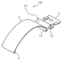
また、本実施の形態1では、バネ部130が照明器具1000の長手方向へ2箇所配置される取付機構を説明したが、図13に示す照明器具2000のように、長手片側が引っ掛けによる係合で、もう一方がバネ部による取り付けであっても良い。なお照明器具2000を示す図13では、本体部及び光源部の構成が照明器具1000と異なるため、本体部を本体部100’と記し、光源部を光源部200’と記している。
Further, in the first embodiment, the mounting mechanism in which the
また、本実施の形態1では、対になるバネ部130がお互いに反対方向へ開くように可動する配置に関して説明をおこなったが、互いに向かい合って開くよう可動する配置でもよく、同じ方向へ開くような配置(例えば図3で2個のバネ部130が同じ方向(長手方向を示す矢印側)へ向く)しても良い。
In the first embodiment, the arrangement in which the pair of
なお、実施の形態1では本体部100にバネ部130を設け、光源部200に連結金具250を設ける仕様について説明を行なったが、本体部100が連結金具250を備え、光源部200がバネ部10を備える仕様でもよい。
In the first embodiment, the specifications for providing the
1000,2000 照明器具、100 本体部、111 凹部、112 取付部、113 光源固定部、113a 光源挿入部、113b 光源受部、114 傾斜部、115 蓋部、116 ネジ、120 端子台、120a 端子台コネクタ、130,130a,130b バネ部、200 光源部、210 LEDユニット、220 保持部、220a 保持正面部、220b 保持側面部、220c 連結金具取付台、220c−1 ネジ、230 カバー部、230a カバー爪部、230b カバー当接部、230c カバー拡散部、240 光源蓋部、250 連結金具、250a バネ挿入部、250a−1 バネ挿入孔、250a−1−1 開口縁部、250a−2 バネ受部、250a−3 はずれ止受部、250b 金具固定部、250b−1 摺動補助部、260 はずれ止部、260a 嵌合部、260b 係合カバー部、261a クリップ部、270 点灯装置、270a 点灯装置本体部、270b 電源コネクタ、L1 第1平坦部、L2 第2平坦部、L3 第3平坦部、L4 第4平坦部、M1 第1曲げ部、M2 第2曲げ部、M3 第3曲げ部、M4 第4曲げ部、E 円弧部、K 屈曲部。 1000, 2000 luminaire, 100 body part, 111 recess, 112 mounting part, 113 light source fixing part, 113a light source insertion part, 113b light source receiving part, 114 inclined part, 115 lid part, 116 screw, 120 terminal block, 120a terminal block Connector, 130, 130a, 130b Spring part, 200 Light source part, 210 LED unit, 220 Holding part, 220a Holding front part, 220b Holding side part, 220c Connecting bracket mounting base, 220c-1 Screw, 230 cover part, 230a Cover claw Part, 230b cover contact part, 230c cover diffusion part, 240 light source cover part, 250 coupling bracket, 250a spring insertion part, 250a-1 spring insertion hole, 250a-1-1 opening edge part, 250a-2 spring receiving part, 250a-3 Detachment stop, 250b Bracket fixing part, 250b -1 Sliding assist part, 260 Non-stop part, 260a Fitting part, 260b Engagement cover part, 261a Clip part, 270 lighting device, 270a lighting device body part, 270b Power connector, L1 first flat part, L2 second A flat part, L3 3rd flat part, L4 4th flat part, M1 1st bending part, M2 2nd bending part, M3 3rd bending part, M4 4th bending part, E circular arc part, K bending part.
Claims (5)
前記光源部と前記本体部とのどちらかに取り付けられる長手形状の板バネであるバネ部であって、長手方向に向かう平坦部と、前記平坦部の終わりから前記光源部と前記本体部とのうち取り付けられない方に向かって凸となる円弧形状の円弧形状部とを有し、前記平坦部で前記光源部と前記本体部とのどちらかに取り付けられるバネ部と、
前記光源部と前記本体部とのうち前記バネ部が取り付けられない方に取り付けられる連結部であって、前記円弧形状部を貫通させる開口が形成され、前記平坦部の終わり付近の前記円弧形状部である付近円弧形状部を、無負荷状態に対して変位させた状態で前記開口の周縁が前記付近円弧形状部と当接する連結部と
を備えたことを特徴とする照明装置。 In a lighting device comprising a light source part and a main body part, wherein the light source part is detachably mounted facing the main body part,
A spring part that is a longitudinal leaf spring attached to either the light source part or the main body part, and a flat part that extends in the longitudinal direction, and the light source part and the main body part from the end of the flat part A circular arc-shaped portion that is convex toward the side that cannot be attached, and a spring portion that is attached to either the light source portion or the main body portion at the flat portion;
The connecting part that is attached to the light source part and the main body part to which the spring part is not attached, and an opening that penetrates the arc-shaped part is formed, and the arc-shaped part near the end of the flat part An illuminating device comprising: a connecting portion in which a peripheral arc-shaped portion is a displacement with respect to a no-load state and a peripheral edge of the opening abuts on the near-arc-shaped portion.
前記平坦部とは反対の端部に、屈曲された屈曲部が形成されたことを特徴とする請求項1に記載の照明装置。 The arc-shaped portion of the spring portion is
The lighting device according to claim 1, wherein a bent portion is formed at an end opposite to the flat portion.
複数個の前記バネ部と、各バネ部に対応する各連結部とが取り付けられることを特徴とする請求項2に記載の照明装置。 The main body portion and the front Symbol source unit,
The lighting device according to claim 2, wherein a plurality of the spring portions and each connection portion corresponding to each spring portion are attached.
前記光源部が前記本体部から取り外された状態で前記屈曲部が前記開口の周縁に引っ掛かることで、前記光源部の自重が支持されることを特徴とする請求項3に記載の照明装置。 The lighting device includes:
4. The lighting device according to claim 3, wherein the bent portion is caught on a peripheral edge of the opening in a state in which the light source unit is detached from the main body unit, whereby the self-weight of the light source unit is supported.
前記本体部に取り付けられ、
前記連結部は、
前記光源部に取り付けられたことを特徴とする請求項1〜4のいずれかに記載の照明装置。 The spring portion is
Attached to the main body,
The connecting portion is
The lighting device according to claim 1, wherein the lighting device is attached to the light source unit.
Priority Applications (5)
| Application Number | Priority Date | Filing Date | Title |
|---|---|---|---|
| JP2014037095A JP6258071B2 (en) | 2014-02-27 | 2014-02-27 | Lighting device |
| CN201811064889.4A CN109163261B (en) | 2014-02-27 | 2015-02-23 | Lighting apparatus |
| CN201811064890.7A CN109140321B (en) | 2014-02-27 | 2015-02-23 | Lighting device |
| PCT/JP2015/055083 WO2015129637A1 (en) | 2014-02-27 | 2015-02-23 | Spring for illumination device, illumination device, and illumination apparatus |
| CN201580010662.XA CN106030205B (en) | 2014-02-27 | 2015-02-23 | Lighting device and lighting device spring |
Applications Claiming Priority (1)
| Application Number | Priority Date | Filing Date | Title |
|---|---|---|---|
| JP2014037095A JP6258071B2 (en) | 2014-02-27 | 2014-02-27 | Lighting device |
Related Child Applications (1)
| Application Number | Title | Priority Date | Filing Date |
|---|---|---|---|
| JP2017234155A Division JP6626077B2 (en) | 2017-12-06 | 2017-12-06 | Lighting equipment |
Publications (3)
| Publication Number | Publication Date |
|---|---|
| JP2015162366A JP2015162366A (en) | 2015-09-07 |
| JP2015162366A5 JP2015162366A5 (en) | 2017-03-30 |
| JP6258071B2 true JP6258071B2 (en) | 2018-01-10 |
Family
ID=54185340
Family Applications (1)
| Application Number | Title | Priority Date | Filing Date |
|---|---|---|---|
| JP2014037095A Active JP6258071B2 (en) | 2014-02-27 | 2014-02-27 | Lighting device |
Country Status (1)
| Country | Link |
|---|---|
| JP (1) | JP6258071B2 (en) |
Families Citing this family (4)
| Publication number | Priority date | Publication date | Assignee | Title |
|---|---|---|---|---|
| WO2016111298A1 (en) * | 2015-01-05 | 2016-07-14 | ローム株式会社 | Led illumination device |
| JP6480854B2 (en) * | 2015-12-09 | 2019-03-13 | 株式会社ササクラ | Electronic circuit unit fixing method and fixture |
| JPWO2018003907A1 (en) * | 2016-06-30 | 2019-04-18 | 興和株式会社 | Lighting device |
| JP2019175873A (en) * | 2019-07-17 | 2019-10-10 | 三菱電機株式会社 | Illumination device |
Family Cites Families (4)
| Publication number | Priority date | Publication date | Assignee | Title |
|---|---|---|---|---|
| JP5702273B2 (en) * | 2009-02-19 | 2015-04-15 | ローム株式会社 | LED lighting device |
| JP4637251B2 (en) * | 2009-06-10 | 2011-02-23 | シャープ株式会社 | Lighting equipment |
| JP5610622B2 (en) * | 2010-08-31 | 2014-10-22 | パナソニック株式会社 | lighting equipment |
| JP5885985B2 (en) * | 2011-10-03 | 2016-03-16 | シャープ株式会社 | Lighting device |
-
2014
- 2014-02-27 JP JP2014037095A patent/JP6258071B2/en active Active
Also Published As
| Publication number | Publication date |
|---|---|
| JP2015162366A (en) | 2015-09-07 |
Similar Documents
| Publication | Publication Date | Title |
|---|---|---|
| JP6271296B2 (en) | lighting equipment | |
| JP6258072B2 (en) | lighting equipment | |
| JP6258071B2 (en) | Lighting device | |
| JP6376773B2 (en) | Spring for lighting device and lighting device | |
| JP5623209B2 (en) | Lighting apparatus and method of assembling the lighting apparatus | |
| JP6311987B2 (en) | lighting equipment | |
| JP2018037418A (en) | Lighting fixture | |
| WO2015129637A1 (en) | Spring for illumination device, illumination device, and illumination apparatus | |
| JP2018110135A (en) | Illuminating device spring and illuminating device | |
| JP2017224633A (en) | Lighting fixture | |
| JP6665152B2 (en) | lighting equipment | |
| JP6198890B2 (en) | Mounting spring for light fixture and light source unit | |
| JP6192772B2 (en) | Lighting apparatus and method of attaching the lighting apparatus | |
| JP6095831B2 (en) | lighting equipment | |
| JP6293204B2 (en) | lighting equipment | |
| JP6230657B2 (en) | Lighting fixture and mounting spring for lighting fixture | |
| JP6509313B2 (en) | lighting equipment | |
| JP6448752B2 (en) | lighting equipment | |
| JP6017082B2 (en) | Mounting spring for light fixture and light source unit | |
| JP6293203B2 (en) | lighting equipment | |
| TWI696787B (en) | Supporting member for ceiling installation appliance, ceiling installation appliance and method for disassembling ceiling installation appliance | |
| KR20170052249A (en) | Apparatus mounting for lighting lamp | |
| JP6793790B2 (en) | Light source unit and lighting equipment | |
| JP6735876B2 (en) | lighting equipment | |
| JP6160203B2 (en) | Downlight |
Legal Events
| Date | Code | Title | Description |
|---|---|---|---|
| A621 | Written request for application examination |
Free format text: JAPANESE INTERMEDIATE CODE: A621 Effective date: 20170208 |
|
| A521 | Request for written amendment filed |
Free format text: JAPANESE INTERMEDIATE CODE: A523 Effective date: 20170221 |
|
| TRDD | Decision of grant or rejection written | ||
| A01 | Written decision to grant a patent or to grant a registration (utility model) |
Free format text: JAPANESE INTERMEDIATE CODE: A01 Effective date: 20171107 |
|
| A61 | First payment of annual fees (during grant procedure) |
Free format text: JAPANESE INTERMEDIATE CODE: A61 Effective date: 20171206 |
|
| R150 | Certificate of patent or registration of utility model |
Ref document number: 6258071 Country of ref document: JP Free format text: JAPANESE INTERMEDIATE CODE: R150 |
|
| R250 | Receipt of annual fees |
Free format text: JAPANESE INTERMEDIATE CODE: R250 |
|
| R250 | Receipt of annual fees |
Free format text: JAPANESE INTERMEDIATE CODE: R250 |
|
| R250 | Receipt of annual fees |
Free format text: JAPANESE INTERMEDIATE CODE: R250 |
|
| R250 | Receipt of annual fees |
Free format text: JAPANESE INTERMEDIATE CODE: R250 |