JP6504040B2 - Notification processor - Google Patents
Notification processor Download PDFInfo
- Publication number
- JP6504040B2 JP6504040B2 JP2015234988A JP2015234988A JP6504040B2 JP 6504040 B2 JP6504040 B2 JP 6504040B2 JP 2015234988 A JP2015234988 A JP 2015234988A JP 2015234988 A JP2015234988 A JP 2015234988A JP 6504040 B2 JP6504040 B2 JP 6504040B2
- Authority
- JP
- Japan
- Prior art keywords
- captured image
- specific
- notification
- notification processing
- display
- Prior art date
- Legal status (The legal status is an assumption and is not a legal conclusion. Google has not performed a legal analysis and makes no representation as to the accuracy of the status listed.)
- Active
Links
- 239000003550 marker Substances 0.000 claims description 43
- 238000003384 imaging method Methods 0.000 claims description 35
- 238000004364 calculation method Methods 0.000 claims description 4
- 230000010365 information processing Effects 0.000 claims description 4
- 238000013475 authorization Methods 0.000 claims 2
- 238000000034 method Methods 0.000 description 47
- 238000001994 activation Methods 0.000 description 3
- 238000013500 data storage Methods 0.000 description 2
- 230000000694 effects Effects 0.000 description 2
- 238000009434 installation Methods 0.000 description 2
- 230000002159 abnormal effect Effects 0.000 description 1
- 238000001514 detection method Methods 0.000 description 1
- 238000010586 diagram Methods 0.000 description 1
- 238000003825 pressing Methods 0.000 description 1
- 239000004065 semiconductor Substances 0.000 description 1
- 238000012876 topography Methods 0.000 description 1
Images


Classifications
-
- G—PHYSICS
- G01—MEASURING; TESTING
- G01C—MEASURING DISTANCES, LEVELS OR BEARINGS; SURVEYING; NAVIGATION; GYROSCOPIC INSTRUMENTS; PHOTOGRAMMETRY OR VIDEOGRAMMETRY
- G01C21/00—Navigation; Navigational instruments not provided for in groups G01C1/00 - G01C19/00
- G01C21/26—Navigation; Navigational instruments not provided for in groups G01C1/00 - G01C19/00 specially adapted for navigation in a road network
- G01C21/34—Route searching; Route guidance
- G01C21/36—Input/output arrangements for on-board computers
- G01C21/3602—Input other than that of destination using image analysis, e.g. detection of road signs, lanes, buildings, real preceding vehicles using a camera
-
- B—PERFORMING OPERATIONS; TRANSPORTING
- B60—VEHICLES IN GENERAL
- B60R—VEHICLES, VEHICLE FITTINGS, OR VEHICLE PARTS, NOT OTHERWISE PROVIDED FOR
- B60R1/00—Optical viewing arrangements; Real-time viewing arrangements for drivers or passengers using optical image capturing systems, e.g. cameras or video systems specially adapted for use in or on vehicles
- B60R1/20—Real-time viewing arrangements for drivers or passengers using optical image capturing systems, e.g. cameras or video systems specially adapted for use in or on vehicles
- B60R1/22—Real-time viewing arrangements for drivers or passengers using optical image capturing systems, e.g. cameras or video systems specially adapted for use in or on vehicles for viewing an area outside the vehicle, e.g. the exterior of the vehicle
- B60R1/23—Real-time viewing arrangements for drivers or passengers using optical image capturing systems, e.g. cameras or video systems specially adapted for use in or on vehicles for viewing an area outside the vehicle, e.g. the exterior of the vehicle with a predetermined field of view
- B60R1/24—Real-time viewing arrangements for drivers or passengers using optical image capturing systems, e.g. cameras or video systems specially adapted for use in or on vehicles for viewing an area outside the vehicle, e.g. the exterior of the vehicle with a predetermined field of view in front of the vehicle
-
- B—PERFORMING OPERATIONS; TRANSPORTING
- B60—VEHICLES IN GENERAL
- B60W—CONJOINT CONTROL OF VEHICLE SUB-UNITS OF DIFFERENT TYPE OR DIFFERENT FUNCTION; CONTROL SYSTEMS SPECIALLY ADAPTED FOR HYBRID VEHICLES; ROAD VEHICLE DRIVE CONTROL SYSTEMS FOR PURPOSES NOT RELATED TO THE CONTROL OF A PARTICULAR SUB-UNIT
- B60W30/00—Purposes of road vehicle drive control systems not related to the control of a particular sub-unit, e.g. of systems using conjoint control of vehicle sub-units, or advanced driver assistance systems for ensuring comfort, stability and safety or drive control systems for propelling or retarding the vehicle
- B60W30/14—Adaptive cruise control
-
- B—PERFORMING OPERATIONS; TRANSPORTING
- B60—VEHICLES IN GENERAL
- B60W—CONJOINT CONTROL OF VEHICLE SUB-UNITS OF DIFFERENT TYPE OR DIFFERENT FUNCTION; CONTROL SYSTEMS SPECIALLY ADAPTED FOR HYBRID VEHICLES; ROAD VEHICLE DRIVE CONTROL SYSTEMS FOR PURPOSES NOT RELATED TO THE CONTROL OF A PARTICULAR SUB-UNIT
- B60W50/00—Details of control systems for road vehicle drive control not related to the control of a particular sub-unit, e.g. process diagnostic or vehicle driver interfaces
- B60W50/08—Interaction between the driver and the control system
- B60W50/14—Means for informing the driver, warning the driver or prompting a driver intervention
-
- G—PHYSICS
- G01—MEASURING; TESTING
- G01C—MEASURING DISTANCES, LEVELS OR BEARINGS; SURVEYING; NAVIGATION; GYROSCOPIC INSTRUMENTS; PHOTOGRAMMETRY OR VIDEOGRAMMETRY
- G01C21/00—Navigation; Navigational instruments not provided for in groups G01C1/00 - G01C19/00
- G01C21/26—Navigation; Navigational instruments not provided for in groups G01C1/00 - G01C19/00 specially adapted for navigation in a road network
-
- G—PHYSICS
- G05—CONTROLLING; REGULATING
- G05D—SYSTEMS FOR CONTROLLING OR REGULATING NON-ELECTRIC VARIABLES
- G05D1/00—Control of position, course or altitude of land, water, air, or space vehicles, e.g. automatic pilot
- G05D1/0055—Control of position, course or altitude of land, water, air, or space vehicles, e.g. automatic pilot with safety arrangements
- G05D1/0061—Control of position, course or altitude of land, water, air, or space vehicles, e.g. automatic pilot with safety arrangements for transition from automatic pilot to manual pilot and vice versa
-
- G—PHYSICS
- G06—COMPUTING; CALCULATING OR COUNTING
- G06V—IMAGE OR VIDEO RECOGNITION OR UNDERSTANDING
- G06V10/00—Arrangements for image or video recognition or understanding
- G06V10/70—Arrangements for image or video recognition or understanding using pattern recognition or machine learning
- G06V10/74—Image or video pattern matching; Proximity measures in feature spaces
- G06V10/75—Organisation of the matching processes, e.g. simultaneous or sequential comparisons of image or video features; Coarse-fine approaches, e.g. multi-scale approaches; using context analysis; Selection of dictionaries
- G06V10/751—Comparing pixel values or logical combinations thereof, or feature values having positional relevance, e.g. template matching
-
- G—PHYSICS
- G06—COMPUTING; CALCULATING OR COUNTING
- G06V—IMAGE OR VIDEO RECOGNITION OR UNDERSTANDING
- G06V20/00—Scenes; Scene-specific elements
- G06V20/50—Context or environment of the image
- G06V20/56—Context or environment of the image exterior to a vehicle by using sensors mounted on the vehicle
- G06V20/58—Recognition of moving objects or obstacles, e.g. vehicles or pedestrians; Recognition of traffic objects, e.g. traffic signs, traffic lights or roads
- G06V20/582—Recognition of moving objects or obstacles, e.g. vehicles or pedestrians; Recognition of traffic objects, e.g. traffic signs, traffic lights or roads of traffic signs
-
- G—PHYSICS
- G08—SIGNALLING
- G08G—TRAFFIC CONTROL SYSTEMS
- G08G1/00—Traffic control systems for road vehicles
- G08G1/16—Anti-collision systems
-
- B—PERFORMING OPERATIONS; TRANSPORTING
- B60—VEHICLES IN GENERAL
- B60W—CONJOINT CONTROL OF VEHICLE SUB-UNITS OF DIFFERENT TYPE OR DIFFERENT FUNCTION; CONTROL SYSTEMS SPECIALLY ADAPTED FOR HYBRID VEHICLES; ROAD VEHICLE DRIVE CONTROL SYSTEMS FOR PURPOSES NOT RELATED TO THE CONTROL OF A PARTICULAR SUB-UNIT
- B60W50/00—Details of control systems for road vehicle drive control not related to the control of a particular sub-unit, e.g. process diagnostic or vehicle driver interfaces
- B60W50/08—Interaction between the driver and the control system
- B60W50/14—Means for informing the driver, warning the driver or prompting a driver intervention
- B60W2050/143—Alarm means
-
- B—PERFORMING OPERATIONS; TRANSPORTING
- B60—VEHICLES IN GENERAL
- B60W—CONJOINT CONTROL OF VEHICLE SUB-UNITS OF DIFFERENT TYPE OR DIFFERENT FUNCTION; CONTROL SYSTEMS SPECIALLY ADAPTED FOR HYBRID VEHICLES; ROAD VEHICLE DRIVE CONTROL SYSTEMS FOR PURPOSES NOT RELATED TO THE CONTROL OF A PARTICULAR SUB-UNIT
- B60W50/00—Details of control systems for road vehicle drive control not related to the control of a particular sub-unit, e.g. process diagnostic or vehicle driver interfaces
- B60W50/08—Interaction between the driver and the control system
- B60W50/14—Means for informing the driver, warning the driver or prompting a driver intervention
- B60W2050/146—Display means
Landscapes
- Engineering & Computer Science (AREA)
- Radar, Positioning & Navigation (AREA)
- Remote Sensing (AREA)
- Automation & Control Theory (AREA)
- Physics & Mathematics (AREA)
- General Physics & Mathematics (AREA)
- Multimedia (AREA)
- Mechanical Engineering (AREA)
- Computer Vision & Pattern Recognition (AREA)
- Theoretical Computer Science (AREA)
- Transportation (AREA)
- Aviation & Aerospace Engineering (AREA)
- Human Computer Interaction (AREA)
- Databases & Information Systems (AREA)
- General Health & Medical Sciences (AREA)
- Medical Informatics (AREA)
- Software Systems (AREA)
- Evolutionary Computation (AREA)
- Computing Systems (AREA)
- Artificial Intelligence (AREA)
- Health & Medical Sciences (AREA)
- Traffic Control Systems (AREA)
- Navigation (AREA)
- Control Of Driving Devices And Active Controlling Of Vehicle (AREA)
Description
本発明は、車両に用いられる報知処理装置に関する。 The present invention relates to a notification processing device used for a vehicle.
自動走行が可能な車両として、特許文献1には、道路標識及び路面に描かれた道路標示を車両に搭載されたCCDカメラにより検出し、ドライバが行う運転操作のうち、アクセル操作、ブレーキ操作及びステアリング操作を自動で行う車両が開示されている。
As a vehicle capable of automatically traveling,
この種の車両として、ドライバが行う運転操作のうち、少なくともアクセル操作、ブレーキ操作及びステアリング操作を自動で行う自動運転制御を実行する自動運転モードと、自動運転制御を実行しない手動運転モードと、の間で車両の運転モードがドライバの操作により切替可能に構成される車両が挙げられる。このような車両は、例えば次のような走行環境で利用され得る。すなわち、自動走行が許可される区間である許可区間と自動走行が禁止される区間である禁止区間とに道路が区分され、許可区間が開始される地点に許可区間の開始を表す道路標識や道路標示などの標示物である開始標示物が設けられる。そして、車両が禁止区間から許可区間に入る際にドライバが運転モードを手動運転モードから自動運転モードに切り替える。 As a vehicle of this type, an automatic operation mode for executing automatic operation control for automatically performing at least an accelerator operation, a brake operation and a steering operation among driving operations performed by a driver, and a manual operation mode for not performing automatic operation control Among the vehicles, the operation mode of the vehicle can be switched by the operation of the driver. Such a vehicle can be used, for example, in the following traveling environment. That is, the road is divided into a permitted section, which is a section where automatic travel is permitted, and a prohibited section, which is a section where automatic travel is prohibited, and a road sign or road indicating the start of the permitted section at the point where the permitted section is started. A starting marking is provided, which is a marking such as a marking. Then, when the vehicle enters the permitted section from the prohibited section, the driver switches the operation mode from the manual operation mode to the automatic operation mode.
このような状況の下、車両が開始標示物を検出し、許可区間の開始をドライバに報知するような構成を想定すると、報知を受けたドライバが安心して車両の運転モードを切り替えられない場合がある。すなわち、車両の運転中に車内スピーカ等で車両が許可区間に入った旨の報知を行っただけでは、ドライバはその報知内容が正しいかどうか確信を持つことができないまま運転モードを切り替えなければならない場合が起こり得る。 Under such circumstances, assuming that the vehicle detects the start sign and informs the driver of the start of the permitted section, the driver who has received the notification may not be able to switch the vehicle operation mode with confidence. is there. That is, only by notifying that the vehicle has entered the permission section by using an in-vehicle speaker or the like while driving the vehicle, the driver must switch the operation mode without being able to be certain whether the notification content is correct or not Cases can happen.
本発明は、こうした問題にかんがみてなされたものであり、車両が禁止区間から許可区間に入る際に、ドライバが車両の報知内容に対して安心して運転モードを切り替えることができることを目的とする。 The present invention has been made in view of these problems, and it is an object of the present invention to allow the driver to switch the driving mode with confidence for the notification content of the vehicle when the vehicle enters the permitted section from the prohibited section.
本発明の一側面は、ドライバが行う運転操作のうち、少なくともアクセル操作、ブレーキ操作及びステアリング操作を自動で行う自動運転制御を実行する自動運転モードと、自動運転制御を実行しない手動運転モードと、の走行が可能な車両(1)で用いられ、ドライバに対して報知を行うための報知処理装置(35)である。報知処理装置は、画像取得部(S15,S227,S257)と、認識部(S16,S228,S258)と、第1報知処理部(S20,S21,S23,S24,S221,S251)と、第2報知処理部(S20,S21,S23,S24,S221,S251)と、を備える。画像取得部は、車両の前方を撮像する撮像装置(31)から撮像画像を取得する。認識部は、画像取得部により取得された撮像画像において、特定の標示物である特定標示物(21〜26)を認識する。第1報知処理部は、特定標示物が映った撮像画像である特定撮像画像を車両内の表示装置(33)に表示する。第2報知処理部は、特定撮像画像の表示とは異なる報知態様により報知を行う。認識部は、画像取得部により取得された撮像画像において、自動運転モードでの走行が許可される区間である許可区間の開始を表す標示物である開始標示物(23)を特定標示物として認識する。第1報知処理部は、認識部により開始標示物が認識された場合に、開始標示物が映った撮像画像である開始撮像画像を特定撮像画像として表示装置に表示する。第2報知処理部は、認識部により開始標示物が認識された場合に、開始撮像画像の表示とは異なる報知態様により許可区間の開始を報知する。 According to one aspect of the present invention, there is provided an automatic operation mode for executing automatic operation control for automatically performing at least an accelerator operation, a brake operation, and a steering operation among driving operations performed by a driver, and a manual operation mode for not performing automatic operation control. The notification processing device (35) is used in a vehicle (1) capable of traveling in the vehicle and for notifying a driver. The notification processing device includes an image acquisition unit (S15, S227, S257), a recognition unit (S16, S228, S258), a first notification processing unit (S20, S21, S23, S24, S221, S251), and a second And a notification processing unit (S20, S21, S23, S24, S221, S251). The image acquisition unit acquires a captured image from an imaging device (31) that captures the front of the vehicle. The recognition unit recognizes a specific marking object (21 to 26) that is a specific marking object in the captured image acquired by the image acquisition unit. The first notification processing unit displays a specific captured image, which is a captured image on which a specific sign object appears, on a display device (33) in the vehicle. The second notification processing unit performs notification in a notification mode different from the display of the specific captured image. The recognition unit recognizes the start sign object (23), which is a sign object representing the start of a permitted section, which is a section in which traveling in the automatic driving mode is permitted, in the captured image acquired by the image acquisition unit as a specific sign object Do. The first notification processing unit, when the start sign object is recognized by the recognition unit, displays the start captured image, which is a captured image on which the start sign object appears, as a specific captured image on the display device. The second notification processing unit reports the start of the permitted section in a notification mode different from the display of the start pickup image when the start indicator object is recognized by the recognition unit.
このような構成では、認識部により開始標示物が認識された場合に、第2報知処理部による報知が行われ、また、これに加えて第1報知処理部により開始標示物が映った撮像画像である開始撮像画像が表示装置に表示される。つまり、車両の運転中にドライバが目視可能な開始標示物の実際の画像が表示装置に表示される。そして、ドライバは、表示された開始撮像画像と自らが目視した内容とを照合し、両者が一致していれば車両の報知内容が正しいとの確信を持って車両の運転モードを自動運転モードに切り替えることができる。したがって、車両の報知内容に対して安心して運転モードを切り替えることができる。 In such a configuration, when the start sign object is recognized by the recognition unit, the second notification processing unit performs notification, and in addition to this, the first notification processing unit displays a captured image in which the start indication object appears The start pickup image which is is displayed on the display device. That is, an actual image of the start sign visible to the driver while driving the vehicle is displayed on the display device. Then, the driver collates the displayed start captured image with the content visually observed by the driver, and if both are in agreement, the driving mode of the vehicle is switched to the automatic driving mode with certainty that the notification content of the vehicle is correct. It can be switched. Therefore, the driving mode can be switched with confidence for the notification content of the vehicle.
なお、この欄及び特許請求の範囲に記載した括弧内の符号は、一つの態様として後述する実施形態に記載の具体的手段との対応関係を示すものであって、本発明の技術的範囲を限定するものではない。 In addition, the reference numerals in the parentheses described in this column and the claims indicate the correspondence with specific means described in the embodiment described later as one aspect, and the technical scope of the present invention It is not limited.
以下、図面を参照しながら、発明を実施するための形態を説明する。
[1.前提]
まず、本発明の一実施形態の前提となる事項を図1及び図2を用いて説明する。図1及び図2に示す車両1は、2種類の運転モード、具体的には、自動運転モードと手動運転モードとで走行可能である。
Hereinafter, embodiments of the present invention will be described with reference to the drawings.
[1. Assumptions]
First, the premise of an embodiment of the present invention will be described with reference to FIGS. 1 and 2. The
自動運転モードは、ドライバが行う運転操作のうち、アクセル操作、ブレーキ操作及びステアリング操作を自動で行う自動運転制御を実行する運転モードである。つまり、自動運転モードでは、アクセル操作、ブレーキ操作及びステアリング操作はドライバの操作を一切必要とすることなく行われる。一方、手動運転モードは、自動運転制御を実行しない運転モード、つまり通常の運転モードである。 The automatic driving mode is a driving mode for executing automatic driving control in which an accelerator operation, a brake operation and a steering operation are automatically performed among driving operations performed by the driver. That is, in the automatic driving mode, the accelerator operation, the brake operation and the steering operation are performed without any need for the driver's operation. On the other hand, the manual operation mode is an operation mode in which automatic operation control is not performed, that is, a normal operation mode.
本実施形態では、運転モードは、図2に示すように、車両1のステアリングホイール10に設けられた切替スイッチ32をドライバが押すことにより切り替えられる。つまり、運転モードは、ドライバの操作により切り替えられる。
In the present embodiment, as shown in FIG. 2, the driving mode is switched by the driver pressing the
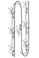
また、本実施形態では、自動運転モードでの走行である自動走行が許可される区間である許可区間が道路の一部に設けられ、許可区間以外の区間は自動走行が禁止される区間である禁止区間である。図1に示すように、許可区間の開始位置には許可区間の開始を表す道路標識である開始標識23が設けられ、許可区間の終了位置には許可区間の終了を表す道路標識である終了標識26が設けられる。本実施形態では、開始標識23は「ここから自動走行許可」と書かれた道路標識であり、終了標識26は「ここから自動走行禁止」と書かれた道路標識である。
Further, in the present embodiment, a permitted section, which is a section permitted to run automatically in the automatic driving mode, is provided in a part of the road, and a section other than the permitted section is a section prohibited from being automatically run. It is a prohibited section. As shown in FIG. 1, a
また、禁止区間における開始標識23の手前には、許可区間の開始を予告する道路標識である開始予告標識22が設けられ、許可区間における終了標識26の手前には、許可区間の終了を予告する道路標識である終了予告標識25が設けられる。なお、本実施形態では、開始予告標識22は「この先自動走行許可」と書かれた道路標識であり、終了予告標識25は「この先自動走行禁止」と書かれた道路標識である。
In addition, the
さらに、禁止区間には、当該区間が禁止区間であることを示す道路標識である禁止標識21が所々設置されており、許可区間には、当該区間が許可区間であることを示す道路標識である許可標識24が所々設置されている。本実施形態では、禁止標識21は「禁止区間」と書かれた道路標識であり、許可標識24は「許可区間」と書かれた道路標識である。
Furthermore, in the prohibited section, the prohibited
このように、禁止標識21、開始予告標識22、開始標識23、許可標識24、終了予告標識25及び終了標識26は、この順番で道路に設置される。
[2.構成]
次に、本発明の一実施形態の構成について説明する。図3に示す報知システム30は、車両1で用いられ、撮像装置31、切替スイッチ32、表示装置33、スピーカ34、制御装置35、駆動力制御装置36、制動力制御装置37及び操舵制御装置38を備える。
Thus, the
[2. Constitution]
Next, the configuration of an embodiment of the present invention will be described. The
撮像装置31は、車両1の前部、具体的には、図2に示すように車室内におけるバックミラーの隣りに設けられた車載カメラである。撮像装置31は、車両1の前方を撮像し、撮像した撮像画像を制御装置35へ出力する。
The
切替スイッチ32は、車両1の運転モードを自動運転モードと手動運転モードとの間で切り替えるためのスイッチである。
表示装置33は、画像を表示可能に構成された装置、いわゆるディスプレイである。表示装置33は、図2に示すように、表示された画像をドライバが視認できるような位置、具体的にはインストルメントパネルに設けられる。
The
The
スピーカ34は、音を出力可能に構成された装置である。
制御装置35は、CPU351、ROM352、RAM353等を構成要素とするマイクロコンピュータを備える。制御装置35は、撮像装置31から取得した撮像画像に基づいて、白線や歩行者や車両等を認識し、自動走行のための制御量を演算する。制御装置35は、演算した制御量を駆動力制御装置36、制動力制御装置37及び操舵制御装置38へ出力する。
The
The
また、制御装置35、具体的にはCPU351は、非遷移的実体的記録媒体であるROM352に記録されているプログラムに従い、図4〜図7に示す後述する報知処理を実行する。
Further, the
駆動力制御装置36は、制御装置35から入力された制御量に基づいて駆動力を制御する。
制動力制御装置37は、制御装置35から入力された制御量に基づいて制動力を制御する。
The driving
The braking
操舵制御装置38は、制御装置35から入力された制御量に基づいて操舵制御を行う。
[3.処理]
次に、制御装置35が実行する報知処理について、図4〜図7のフローチャートを用いて説明する。報知処理は、車両1のイグニッションスイッチがオンにされることにより開始される。また、車両1のイグニッションスイッチがオンにされた時点、換言すれば、報知処理が開始された時点では、車両1の運転モードは手動運転モードに設定されている。なお、本実施形態では、車両1の起動時には、車両1が禁止区間に位置することが想定される。
The
[3. processing]
Next, notification processing performed by the
S11で、制御装置35は、車両1の状態を禁止状態にする。ここでいう禁止状態とは、車両1の運転モードを手動運転モードから自動運転モードに切り替えようとする切替スイッチ32の入力が無効になる状態である。車両1の状態としては、禁止状態の他に、車両1の運転モードを自動運転モードに切り替えようとする切替スイッチ32の入力が有効になる状態である許可状態がある。本実施形態では、車両1の状態が禁止状態になってから後述するS222で車両1の状態が許可状態になるまでの間は、運転モードを自動運転モードに切り替えることができない。
At S11, the
S12で、制御装置35は、イグニッションスイッチがオンであるか否かを判定する。
このS12で、制御装置35は、イグニッションスイッチがオンであると判定した場合に、処理をS13へ移行させる。一方、制御装置35は、イグニッションスイッチがオンでない、つまりオフであると判定した場合に、報知処理を終了する。
At S12, the
If it is determined in S12 that the ignition switch is on, the
S13で、制御装置35は、自動走行システムが正常であるか否かを判定する。ここでいう自動走行システムとは、自動走行を行うために必要なセンサ、ECU及びアクチュエータを意味し、本実施形態では、自動走行システムには、撮像装置31、駆動力制御装置36、制動力制御装置37及び操舵制御装置38といった装置が少なくとも含まれる。S13では、制御装置35は、自動走行システムの故障の有無を判定し、故障がある場合に自動走行システムが正常でないと判定し、故障がない場合に自動走行システムが正常であると判定する。
At S13, the
このS13で、制御装置35は、自動走行システムが正常でない、つまり異常であると判定した場合に、処理をS14へ移行させる。
S14で、制御装置35は、自動走行システムの動作を禁止する。具体的には、制御装置35は、運転モードが手動運転モードである状態、つまり自動走行が行われていない状態では、運転モードの自動運転モードへの切替を無効にし、運転モードを切り替えられないようにする。一方、制御装置35は、運転モードが自動運転モードである状態、つまり自動走行が行われている状態では、車両1を路肩等の安全な場所に自動走行させて停車させた後、自動走行システムの動作を停止させる。
If it is determined in S13 that the automatic travel system is not normal, that is, it is determined that the automatic travel system is abnormal, the
At S14, the
制御装置35は、S14の処理を実行すると、前述したS12へ戻り、S12以降の処理を繰り返す。
一方、制御装置35は、前述したS13で自動走行システムが正常であると判定した場合に、処理をS15へ移行させる。
After executing the processing of S14, the
On the other hand, when the
S15で、制御装置35は、撮像装置31から最新の撮像画像を1つ取得する。
S16で、制御装置35は、S15で取得した撮像画像において特定標識を認識したか否かを判定する。ここでいう特定標識とは、特定の道路標識を意味し、本実施形態では、特定標識は、前述した図1に示す禁止標識21、開始予告標識22、開始標識23、許可標識24、終了予告標識25及び終了標識26である。また、本実施形態では、制御装置35は、周知の画像処理であるテンプレートマッチングにより特定標識を認識する。
In S15, the
In S16, the
このS16で、制御装置35は、特定標識を認識していないと判定した場合に、前述したS12へ戻り、S12以降の処理を繰り返す。一方、制御装置35は、特定標識を認識したと判定した場合に、処理をS17へ移行させる。
When it is determined in S16 that the
S17で、制御装置35は、特定標識が順番通りに認識されたか否かを判定する。本実施形態では、S12〜S25のうち少なくともS12〜19は繰り返し実行され、車両1の走行に伴い、道路に沿って間隔を空けて設置された特定標識が順に認識される。前述したように、特定標識は、禁止標識21、開始予告標識22、開始標識23、許可標識24、終了予告標識25、終了標識26の順番で道路に設置される。制御装置35は、道路に設置された特定標識の順番と認識された特定標識の順番とに矛盾がない場合に、特定標識が順番通りに認識されたと判定し、矛盾がある場合に、特定標識が順番通りに認識されていないと判定する。
At S17, the
矛盾がある場合としては、例えば、前回認識されるべき特定標識が認識されず、その結果順番を飛ばして特定標識が認識される場合が挙げられる。なお、前回認識されるべき特定標識が認識されない場合としては、特定標識が他の車両の影に隠れ、特定標識を撮像できなかった場合等が考えられる。 The case where there is a contradiction is, for example, a case where the specific marker to be recognized last time is not recognized, and as a result, the specific marker is recognized by skipping the order. In addition, as a case where the specific label | marker which should be recognized last time is not recognized, the case where a specific label | marker hides in the shadow of another vehicle and it can not image a specific label | marker etc. can be considered.
また、制御装置35は、連続して設置され得る禁止標識21及び許可標識24については、これらの特定標識が連続して認識された場合にも特定標識が順番通りに認識されたと判定する。
In addition, the
このS17で、制御装置35は、特定標識が順番通りに認識されたと判定した場合に、処理をS19へ移行させる。一方、制御装置35は、特定標識が順番通りに認識されていないと判定した場合に、S18で図7に示す例外処理を実行した後、処理をS19へ移行させる。例外処理については後述する。
When it is determined in S17 that the
S19で、制御装置35は、S16で認識された特定標識の種類を判定する。
このS19で、制御装置35は、認識された特定標識が禁止標識21であると判定した場合には、処理をS20へ移行させる。
At S19, the
When it is determined in S19 that the identified specific label is the
S20で、制御装置35は、認識された禁止標識21が映った撮像画像である禁止撮像画像を表示装置33に表示し、また、車両1が禁止区間に位置している旨をスピーカ34に音声出力させる。制御装置35は、例えば、「禁止区間です」といった音声メッセージをスピーカ34に出力させる。
In S20, the
また、本実施形態では、禁止撮像画像などの、特定標識が映った撮像画像である特定撮像画像は、次のように表示装置33に表示される。すなわち、制御装置35は、特定標識のみが映った撮像画像を特定撮像画像として表示装置33に表示する。具体的には、本実施形態では、撮像装置31は特定標識を一部に含む範囲を撮像可能であり、制御装置35は、まず、撮像した撮像画像から認識された特定標識が映った部分のみを切り取る。そして、制御装置35は、図2に示すように、切り取った画像で表示装置33の表示画面が埋まるように、切り取った画像を拡大して表示装置33に表示する。この際、制御装置35は、切り取った画像を静止画像として所定時間(例えば数秒間)表示する。
Further, in the present embodiment, a specific captured image, which is a captured image on which a specific marker appears, such as a prohibited captured image, is displayed on the
制御装置35は、S20の処理を実行すると、前述したS12へ戻り、S12以降の処理を繰り返す。
一方、制御装置35は、前述したS19で、認識された特定標識が開始予告標識22であると判定した場合には、処理をS21へ移行させる。
After executing the processing of S20, the
On the other hand, when it is determined in S19 described above that the recognized specific marker is the
S21で、制御装置35は、認識された開始予告標識22が映った撮像画像である開始予告撮像画像を表示装置33に表示し、また、許可区間の開始を予告する旨をスピーカ34に音声出力させる。制御装置35は、例えば、「間もなく許可区間に入ります」といった音声メッセージをスピーカ34に出力させる。
In S21, the
制御装置35は、S21の処理を実行すると、前述したS12へ戻り、S12以降の処理を繰り返す。
一方、制御装置35は、前述したS19で、認識された特定標識が開始標識23であると判定した場合には、処理をS22へ移行させる。
After executing the process of S21, the
On the other hand, when the
S22で、制御装置35は、自動走行起動処理を実行する。
ここで、自動走行起動処理について、図5のフローチャートを用いて説明する。
S221で、制御装置35は、認識された開始標識23が映った撮像画像である開始撮像画像を表示装置33に表示し、また、許可区間が開始する旨をスピーカ34に音声出力させる。制御装置35は、例えば、「許可区間に入りました」といった音声メッセージをスピーカ34に出力させる。
At S22, the
Here, the automatic travel activation process will be described using the flowchart of FIG.
In S221, the
S222で、制御装置35は、車両1の状態を前述した許可状態にする。
S223で、制御装置35は、ドライバに対して運転モードを自動運転モードに切り替える切替方法を案内する。制御装置35は、例えば、「ステアリングホイールにある切替スイッチを押してください」といった音声メッセージをスピーカ34に出力させることにより切替方法を案内する。
At S222, the
In S223, the
S224で、制御装置35は、切替スイッチ32の操作があったか否かを判定する。制御装置35は、切替スイッチ32の操作があったと判定した場合に、処理をS225へ移行させる。
At S224, the
S225で、制御装置35は、運転モードを自動運転モードに切り替える。制御装置35は、S225の処理を実行すると、前述したS12へ戻り、S12以降の処理を繰り返す。
At S225, the
一方、制御装置35は、前述したS224で、切替スイッチ32の操作がなかったと判定した場合に、処理をS226へ移行させる。
S226で、制御装置35は、最新のS223の処理を実行してから、つまり切替方法の最新の案内を行ってから一定時間経過したか否かを判定する。制御装置35は、一定時間経過したと判定した場合に、前述したS223へ戻り、S223以降の処理を繰り返す。一方、制御装置35は、一定時間経過していないと判定した場合に、処理をS227へ移行させる。
On the other hand, when it is determined in S224 described above that the
In S226, the
S227及びS228の処理は、前述したS15及びS16と同じであるため、説明を省略する。
このS228で、制御装置35は、特定標識を認識していないと判定した場合に、前述したS223へ戻り、S223以降の処理を繰り返す。一方、制御装置35は、特定標識を認識したと判定した場合に、前述したS17へ戻り、S17以降の処理を繰り返す。
Since the processes of S227 and S228 are the same as S15 and S16 described above, the description will be omitted.
When it is determined in S228 that the
一方、制御装置35は、前述したS19で、認識された特定標識が許可標識24であると判定した場合には、処理をS23へ移行させる。
S23で、制御装置35は、認識された許可標識24が映った撮像画像である許可撮像画像を表示装置33に表示し、また、車両1が許可区間に位置している旨をスピーカ34に音声出力させる。制御装置35は、例えば、「許可区間です」といった音声メッセージをスピーカ34に出力させる。
On the other hand, when it is determined in S19 described above that the recognized specific label is the
In S23, the
制御装置35は、S23の処理を実行すると、前述したS12へ戻り、S12以降の処理を繰り返す。
一方、制御装置35は、前述したS19で、認識された特定標識が終了予告標識25であると判定した場合には、処理をS24へ移行させる。
After executing the processing of S23, the
On the other hand, when the
S24で、制御装置35は、認識された終了予告標識25が映った撮像画像である終了予告撮像画像を表示装置33に表示し、また、許可区間の終了を予告する旨をスピーカ34に音声出力させる。制御装置35は、例えば、「間もなく禁止区間です」といった音声メッセージをスピーカ34に出力させる。
In S24, the
制御装置35は、S24の処理を実行すると、前述したS12へ戻り、S12以降の処理を繰り返す。
一方、制御装置35は、前述したS19で、認識された特定標識が終了標識26であると判定した場合には、処理をS25へ移行させる。
After executing the processing of S24, the
On the other hand, when it is determined in S19 described above that the recognized specific marker is the
S25で、制御装置35は、自動走行終了処理を実行する。
ここで、自動走行終了処理について、図6のフローチャートを用いて説明する。
S251で、制御装置35は、認識された終了標識26が映った撮像画像である終了撮像画像を表示装置33に表示し、また、許可区間が終了する旨をスピーカ34に音声出力させる。制御装置35は、例えば、「禁止区間に入りました」といった音声メッセージをスピーカ34に出力させる。
At S25, the
Here, the automatic travel end processing will be described with reference to the flowchart of FIG.
In S251, the
S252で、制御装置35は、ドライバに対して運転モードを手動運転モードに切り替える切替方法を案内する。制御装置35は、例えば、「ステアリングホイールにある切替スイッチを押してください」といった音声メッセージをスピーカ34に出力させることにより切替方法を案内する。
In S252, the
S253で、制御装置35は、切替スイッチ32の操作があったか否かを判定する。
このS253で、制御装置35は、切替スイッチ32の操作があったと判定した場合に、処理をS254へ移行させる。
In S253, the
When it is determined in S253 that the
S254で、制御装置35は、運転モードを手動運転モードに切り替える。
S255で、制御装置35は、車両1の状態を前述した禁止状態にする。制御装置35は、S255の処理を実行すると、前述したS12へ戻り、S12以降の処理を繰り返す。
In S254, the
In S255, the
一方、制御装置35は、前述したS253で、切替スイッチ32の操作がなかったと判定した場合に、処理をS256へ移行させる。
S256、S257及びS258の処理は、前述したS226、S227及びS228と同じであるため、説明を省略する。
On the other hand, when the
The processes of S256, S257, and S258 are the same as S226, S227, and S228 described above, and thus the description thereof is omitted.
このS258で、制御装置35は、特定標識を認識していないと判定した場合に、前述したS252へ戻り、S252以降の処理を繰り返す。一方、制御装置35は、特定標識を認識したと判定した場合に、前述したS17へ戻り、S17以降の処理を繰り返す。
When it is determined in S258 that the
一方、制御装置35は、前述したS256で一定時間経過したと判定した場合に、処理をS259へ移行させる。
S259で、制御装置35は、前述したS14と同様の処理を実行する。つまり、制御装置35は、車両1を路肩等の安全な場所に自動走行させて停車させた後、自動走行システムの動作を停止させる。このため、本実施形態では、車両1が禁止区間を自動走行し続ける事態が抑制されるようになっている。制御装置35は、S259の処理を実行すると、報知処理を終了する。
On the other hand, when it is determined in S <b> 256 that the predetermined time has elapsed, the
In S259, the
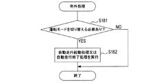
次に、前述したS18で実行される例外処理について、図7のフローチャートを用いて説明する。
S181で、制御装置35は、運転モードを切り替える必要があるか否かを判定する。本実施形態では、制御装置35は、次の(1)〜(5)のいずれかの場合に運転モードを切り替える必要があると判定する。
(1)禁止標識21が認識された後に開始標識23、許可標識24及び終了予告標識25のうちのいずれかが認識された場合。
(2)開始予告標識22が認識された後に許可標識24又は終了予告標識25が認識された場合。
(3)開始標識23又は許可標識24が認識された後に終了標識26、禁止標識21及び開始予告標識22のうちのいずれかが認識された場合。
(4)終了予告標識25が認識された後に禁止標識21又は開始予告標識22が認識された場合。
(5)終了標識26が認識された後に開始標識23、許可標識24及び終了予告標識25のうちのいずれかが認識された場合。
Next, the exception processing executed in S18 described above will be described using the flowchart of FIG.
In S181, the
(1) When any one of the
(2) When the
(3) When any one of the
(4) When the
(5) When any one of the
より具体的には、制御装置35は、上記(1)、(2)及び(5)の場合に、運転モードを自動運転モードに切り替える必要があると判定し、上記(3)及び(4)の場合に、運転モードを手動運転モードに切り替える必要があると判定する。
More specifically, in the above cases (1), (2) and (5), the
このS181で、運転モードを切り替える必要があると判定した場合に、処理をS182へ移行させる。
S182で、制御装置35は、自動走行起動処理又は自動走行終了処理を実行する。ここで、制御装置35は、前述したS181で運転モードを自動運転モードに切り替える必要があると判定した場合に、前述した図5の自動走行起動処理を実行する。一方、前述したS181で運転モードを手動運転モードに切り替える必要があると判定した場合に、前述した図6の自動走行終了処理を実行する。また、制御装置35は、S182において自動走行起動処理を実行するときは、S221において、開始撮像画像の表示装置33への表示は行わず、スピーカ34による音声出力のみを実行する。同様に、制御装置35は、S182において自動走行終了処理を実行するときは、S251において、終了撮像画像の表示装置33への表示は行わず、スピーカ34による音声出力のみを実行する。
If it is determined in S181 that the operation mode needs to be switched, the process proceeds to S182.
In S182, the
制御装置35は、S182の処理を実行すると、例外処理を終了する。
[4.走行シーン例]
次に、ドライバ視点での走行シーン例について説明する。
After executing the processing of S182, the
[4. Running scene example]
Next, a travel scene example from the driver's viewpoint will be described.
まず、ドライバは、禁止区間において、開始予告標識22があるまでの間は、手動運転モードで車両1を走行させる。そして、ドライバは、禁止区間における開始予告標識22と開始標識23との間の区間、つまり許可区間の手前では、運転モードを自動運転モードに切り替える準備をする。
First, the driver causes the
また、ドライバは、禁止区間全般において、車両1のシステム状況、並びに、車両1周辺の特定標識、具体的には禁止標識21、開始予告標識22及び開始標識23の有無、を目視により監視する。なお、禁止区間における走行としては、例えば、ドライバの自宅から許可区間までの走行が挙げられる。
In addition, the driver visually monitors the system status of the
開始標識23の設置場所付近では、ドライバは、表示装置33に表示された開始撮像画像と自らが目視した開始標識23とが一致していることを確認し、運転モードを自動運転モードに切り替える。この際、ドライバは、車両1の周辺状況を確認の上、運転モードを切り替える。
In the vicinity of the installation place of the
許可区間では、ドライバは、車両1のシステム状況、並びに、車両1周辺の特定標識、具体的には許可標識24、終了予告標識25及び終了標識26の有無、を目視により監視する。
In the permission section, the driver visually monitors the system status of the
そして、ドライバは、許可区間における終了予告標識25と終了標識26との間の区間、つまり禁止区間の手前では、運転モードを手動運転モードに切り替える準備をする。
終了標識26の設置場所付近では、ドライバは、表示装置33に表示された終了撮像画像と自らが目視した終了標識26とが一致していることを確認し、運転モードを手動運転モードに切り替える。この際、ドライバは、車両1の周辺状況を確認の上、運転モードを切り替える。
Then, the driver prepares to switch the operation mode to the manual operation mode in the section between the end
In the vicinity of the installation place of the
[5.効果]
以上詳述した実施形態によれば、以下の効果が得られる。
(5a)本実施形態では、制御装置35は、取得された撮像画像において、開始標識23が認識された場合に、開始撮像画像を表示装置33に表示し、また、スピーカ34に音を出力させることにより許可区間の開始を報知する。
[5. effect]
According to the embodiment described above, the following effects can be obtained.
(5a) In the present embodiment, when the
このように、本実施形態では、車両の運転中にドライバが目視可能な開始標識23の実際の画像が表示装置33に表示される。そして、ドライバは、表示された開始撮像画像と自らが目視した内容とが一致していれば、車両の報知内容が正しいとの確信を持って車両の運転モードを自動運転モードに切り替えることができる。したがって、車両の報知内容に対して安心して運転モードを切り替えることができる。
Thus, in the present embodiment, an actual image of the
(5b)本実施形態では、制御装置35は、取得された撮像画像において、終了標識26が認識された場合に、終了撮像画像を表示装置33に表示し、また、スピーカ34に音を出力させることにより許可区間の終了を報知する。
(5b) In the present embodiment, when the
このため、ドライバは、表示装置33に表示された終了撮像画像と自らが目視した内容とが一致していれば、車両の報知内容が正しいとの確信を持って車両の運転モードを手動運転モードに切り替えることができる。
For this reason, if the driver captures the end captured image displayed on the
(5c)本実施形態では、制御装置35は、取得された撮像画像において、開始予告標識22が認識された場合に、開始予告撮像画像を表示装置33に表示し、また、スピーカ34に音を出力させることにより許可区間の開始を予告する旨の報知を行う。
(5c) In the present embodiment, when the
このため、ドライバは、表示装置33に表示された開始予告撮像画像と自らが目視した内容とが一致していれば、車両の報知内容が正しいとの確信を持って、許可区間の手前で自動運転モードへの切替に備えることができる。
For this reason, if the driver sees the start notice captured image displayed on the
(5d)本実施形態では、制御装置35は、取得された撮像画像において、終了予告標識25が認識された場合に、終了予告撮像画像を表示装置33に表示し、また、スピーカ34に音を出力させることにより許可区間の終了を予告する旨の報知を行う。
(5d) In the present embodiment, when the
このため、ドライバは、表示装置33に表示された終了予告撮像画像と自らが目視した内容とが一致していれば、車両の報知内容が正しいとの確信を持って、禁止区間の手前で手動運転モードへの切替に備えることができる。
For this reason, if the driver sees the end notice captured image displayed on the
また、許可区間では、必ずしも運転モードを自動運転モードに切り替える必要はなく、手動運転モードのままで走行することも可能であるが、禁止区間では、自動運転モードでの走行は禁止されており、必ず手動運転モードに切り替えなければならない。本実施形態のように許可区間の終了を予告する旨の報知を行うことで、ドライバが事前に準備することができ、禁止区間を自動運転モードのままで走行し続けることを抑制することができる。 Moreover, in the permitted section, it is not necessary to switch the operation mode to the automatic operation mode, and it is possible to travel in the manual operation mode, but in the prohibited section, traveling in the automatic operation mode is prohibited. Always switch to the manual operation mode. As in the present embodiment, the driver can prepare in advance by notifying the end of the permitted section in advance so that the prohibited section can be prevented from continuing to travel in the automatic operation mode. .
(5e)本実施形態では、制御装置35は、特定標示物のみが映った撮像画像を表示装置33に表示する。したがって、特定標示物を一部に含む範囲の撮像画像を表示装置33に表示する構成と比較して、特定標示物が強調された撮像画像を表示装置33に表示することができる。
(5e) In the present embodiment, the
(5f)本実施形態では、制御装置35は、特定標識が映った撮像画像である特定撮像画像を静止画像として表示装置33に表示する。したがって、特定撮像画像を動画として表示する構成と比較して、表示された画像においてドライバが特定標識を認識しやすくなり、その結果、表示された画像における特定標識と自らが目視した内容とを照合しやすくすることができる。
(5f) In the present embodiment, the
(5g)本実施形態では、制御装置35は、特定撮像画像を表示装置33に表示し、また、スピーカ34に音を出力することで報知を行う。つまり、本実施形態では、特定撮像画像の表示とは異なる報知態様の報知は、スピーカ34に音を出力させることで行われる。したがって、特定撮像画像の表示とは異なる報知態様の報知として、例えば、車室内ランプを点灯させる構成と比較して、車室内ランプを視認しなくてもよいため、運転時に視線を変えることなく報知内容を認識することができる。
(5g) In the present embodiment, the
なお、本実施形態では、禁止標識21、開始予告標識22、開始標識23、許可標識24、終了予告標識25及び終了標識26が特定標示物に相当する。また、開始予告標識22が開始予告標示物に相当し、開始標識23が開始標示物に相当し、終了予告標識25が終了予告標示物に相当し、終了標識26が終了標示物に相当する。また、制御装置35が報知処理装置に相当し、S15,S227及びS257が画像取得部としての処理に相当し、S16,S228及びS258が認識部としての処理に相当する。また、S20,S21,S23,S24,S221及びS251が第1報知処理部及び第2報知処理部としての処理に相当する。
In the present embodiment, the
[6.他の実施形態]
以上、本発明を実施するための形態について説明したが、本発明は上述の実施形態に限定されることなく、種々変形して実施することができる。
[6. Other embodiments]
As mentioned above, although the form for implementing this invention was demonstrated, this invention can be variously deformed and implemented, without being limited to the above-mentioned embodiment.
(6a)上記実施形態では、特定標示物として特定標識21〜26を例示したが、特定標示物はこれに限られるものではない。例えば、特定標示物は、路面に描かれた特定の道路標示である特定道路標示であってもよい。また、制御装置は、例えば、特定標識及び特定道路標示のうちいずれか一方のみを認識してもよく、両方を認識してもよい。
(6a) In the above embodiment, the
(6b)上記実施形態では、制御装置35は、撮像した撮像画像から特定標識が映った部分のみを切り取り、切り取った画像を拡大して表示することにより、特定標識のみが映った撮像画像を表示した。しかし、特定標識のみが映った撮像画像を表示する方法はこれに限られるものではない。制御装置は、例えば、切り取った画像で表示装置33の表示画面が埋まらないように、換言すれば、表示画面において切り取った画像が表示されていない部分が残るように、当該切り取った画像を表示してもよい。
(6b) In the above embodiment, the
また、制御装置35は、特定標識のみが映った撮像画像を特定撮像画像として表示する場合において、特定撮像画像に加え、当該特定撮像画像の地図上の撮像場所である特定撮像場所も表示装置33に表示してもよい。
In addition, when displaying a captured image in which only a specific marker is displayed as a specific captured image, the
具体的には、報知システムを、地図データを記憶可能に構成された装置である地図データ記憶部と、車両1の現在位置を検出可能に構成された位置検出装置と、を更に備える構成にする。ここでいう地図データは、表示装置33に地図を表示する上で必要になる各種データであり、地図データには、道路の形状を示すリンクのデータと、リンクの両端であるノードの位置のデータと、が含まれる。また、地図データには、リンク等により形成される道路の種別、道幅、車線数等を示すデータや建築物や地形等に関するデータ等が含まれる。
Specifically, the notification system further includes a map data storage unit, which is an apparatus configured to be able to store map data, and a position detection apparatus configured to detect the current position of the
そして、制御装置は、地図データ記憶部から地図データを取得する処理と、地図データに基づき、特定撮像場所を算出する処理と、を更に実行し、地図データと算出部により算出された特定撮像場所とに基づき、特定撮像画像と、当該特定撮像画像の特定撮像場所が識別可能に表された地図と、を表示装置33に表示する。このような構成によれば、特定撮像画像のみを表示する構成と比較して、ドライバが、表示された特定撮像画像と自らが目視した内容とをより容易に照合することができる。
Then, the control device further executes a process of acquiring map data from the map data storage unit and a process of calculating a specific imaging place based on the map data, and the map data and the specific imaging place calculated by the calculation unit The
なお、この例では、地図データを取得する処理が地図データ取得部に相当し、地図データに基づき、特定撮像画像の地図上の撮像場所である特定撮像場所を算出する処理が算出部に相当する。 In this example, processing for acquiring map data corresponds to the map data acquisition unit, and processing for calculating a specific imaging location, which is an imaging location on a map of a specific imaging image, based on map data corresponds to a calculation unit. .
(6c)上記実施形態では、特定標識のみが映った撮像画像を特定撮像画像として表示したが、表示態様はこれに限られるもではない。制御装置は、例えば、特定標識、より一般には特定標示物を一部に含む範囲の撮像画像を特定撮像画像として表示装置33に表示してもよい。このような構成によれば、特定標示物に加え特定標示物以外のもの(例えば周囲風景、道路、他の車両及び道路付随物等)も表示されるため、特定標示物のみが映った撮像画像を特定撮像画像として表示する構成と比較して、ドライバが、表示された画像と自らが目視した内容とをより容易に照合することができる。
(6c) In the above embodiment, the captured image in which only the specific marker is shown is displayed as the specific captured image, but the display mode is not limited to this. For example, the control device may display a captured image of a range including a specific marker, more generally, a specific marker in a part of the
また、特定撮像画像に加え、車両1の現在位置及び表示された特定撮像画像の特定撮像場所、車両1の現在位置付近で撮像されたキロポストの撮像画像及び特定撮像場所付近で撮像されたキロポストの撮像画像、並びに、現在時刻及び特定撮像画像が撮像された時刻、なども表示装置33に表示されてもよい。
Further, in addition to the specific captured image, the current position of the
なお、これらは、特定標示物のみが映った撮像画像が表示される場合と特定標示物を一部に含む範囲の撮像画像が表示される場合とのいずれにおいても表示されてもよい。
また、特定標示物のみが映った撮像画像が表示されるモードと特定標示物を一部に含む範囲の撮像画像が表示されるモードとをドライバの操作により切り替えることができるようにしてもよい。
In addition, these may be displayed in any of the case where the captured image in which only the specific marking object is reflected is displayed, and the case where the captured image of the range partially including the specific marking object is displayed.
In addition, it may be possible to switch between a mode in which a captured image in which only a specific sign object is displayed is displayed and a mode in which a captured image in a range partially including the specific sign object is displayed.
(6d)上記実施形態では、制御装置35は、特定撮像画像を静止画像として表示装置33に表示したが、表示態様はこれに限られるものではない。制御装置は、例えば、特定撮像画像を動画として表示してもよい。
(6d) In the embodiment described above, the
(6e)上記実施形態では、制御装置35は、スピーカ34に音声メッセージを出力させることにより特定撮像画像の表示とは異なる報知態様の報知を行ったが、当該報知はこれに限られるものではない。制御装置は、例えば、スピーカ34に音声メッセージ以外の音を出力させることにより報知を行ってもよい。
(6e) In the above embodiment, the
また、制御装置は、例えば、特定撮像画像以外の画像(例えばアイコンなど)を表示装置33に表示させたり、車室内の機器を振動させたり、車室内ランプを点灯させたりなどして報知を行ってもよい。
In addition, the control device performs notification by, for example, displaying an image (for example, an icon or the like) other than the specific captured image on the
(6f)上記実施形態では、撮像画像において特定標識21〜26が認識された場合に報知が行われることでドライバは車両1が禁止区間及び許可区間のいずれに位置しているかを判別可能であった。しかし、区間の判別方法はこれに限られるものではない。例えば、特定標識21〜26に基づく判別に加え、更に次のように判別可能としてもよい。
(6f) In the above embodiment, when the
すなわち、制御装置は、禁止区間及び許可区間の位置の情報を含む地図データを取得する処理と、車両の現在位置を取得する処理と、を更に実行し、取得したこれらの情報に基づいて、車両が禁止区間及び許可区間のいずれに位置しているかを判定し、判定結果をスピーカ34等により報知させてもよい。このような構成によれば、特定標識21〜26が認識されない区間においても、ドライバは車両1が禁止区間及び許可区間のいずれに位置しているかを判別することができる。
That is, the control device further executes a process of acquiring map data including information of positions of prohibited sections and permitted sections, and a process of acquiring the current position of the vehicle, and based on the acquired information, the vehicle It may be determined which of the prohibited section and the permitted section is located, and the determination result may be notified by the
(6g)上記実施形態では、自動運転モードは、ドライバが行う運転操作のうち、アクセル操作、ブレーキ操作及びステアリング操作を自動で行う自動運転制御を実行する運転モードであったが、自動運転モードはこれに限られるものではない。自動運転モードは、例えば、アクセル操作、ブレーキ操作及びステアリング操作に加え、これら以外の操作も自動で実行される運転モードであってもよい。この場合において、自動運転モードは、例えば、ドライバが行う運転操作のすべてを自動で行う完全自動運転制御を実行する運転モードであってもよい。 (6g) In the above embodiment, the automatic driving mode is the driving mode for executing the automatic driving control for automatically performing the accelerator operation, the brake operation and the steering operation among the driving operations performed by the driver. It is not limited to this. The automatic driving mode may be, for example, a driving mode in which operations other than the accelerator operation, the brake operation, and the steering operation are automatically performed. In this case, the automatic operation mode may be, for example, an operation mode for executing a fully automatic operation control that automatically performs all the driving operations performed by the driver.
(6h)上記実施形態で、制御装置35が実行する機能の一部又は全部を、1つあるいは複数のIC等によりハードウェア的に構成してもよい。
(6i)上記実施形態における1つの構成要素が有する機能を複数の構成要素として分散させたり、複数の構成要素が有する機能を1つの構成要素に統合させたりしてもよい。また、上記実施形態の構成の一部を省略してもよい。また、上記実施形態の構成の少なくとも一部を、他の上記実施形態の構成に対して付加又は置換してもよい。なお、特許請求の範囲に記載した文言のみによって特定される技術思想に含まれるあらゆる態様が本発明の実施形態である。
(6h) In the above embodiment, part or all of the functions executed by the
(6i) The function possessed by one component in the above embodiment may be distributed as a plurality of components, or the function possessed by a plurality of components may be integrated into one component. In addition, part of the configuration of the above embodiment may be omitted. In addition, at least a part of the configuration of the above-described embodiment may be added to or replaced with the configuration of the other above-described embodiment. In addition, all the aspects contained in the technical thought specified only by the words described in the claim are an embodiment of the present invention.
(6j)前述した制御装置35の他、当該制御装置35を構成要素とする報知システム30、当該制御装置35としてコンピュータを機能させるためのプログラム、このプログラムを記録した半導体メモリ等の非遷移的実体的記録媒体、特定撮像画像を表示装置33に表示して報知する方法など、種々の形態で本発明を実現することもできる。
(6j) In addition to the
1…車両、21…禁止標識、22…開始予告標識、23…開始標識、24…許可標識、25…終了予告標識、26…終了標識、30…報知システム、31…撮像装置、33…表示装置、34…スピーカ、35…制御装置。
DESCRIPTION OF
Claims (11)
前記車両の前方を撮像する撮像装置(31)から撮像画像を取得する画像取得部(S15,S227,S257)と、
前記画像取得部により取得された前記撮像画像において、特定の標示物である特定標示物(21〜26)を認識する認識部(S16,S228,S258)と、
前記特定標示物が映った前記撮像画像である特定撮像画像を前記車両内の表示装置(33)に表示する第1報知処理部(S20,S21,S23,S24,S221,S251)と、
前記特定撮像画像の表示とは異なる報知態様により報知を行う第2報知処理部(S20,S21,S23,S24,S221,S251)と、
を備え、
前記認識部は、前記画像取得部により取得された前記撮像画像において、前記自動運転モードでの走行が許可される区間である許可区間の開始を表す標示物である開始標示物(23)を前記特定標示物として認識し、
前記第1報知処理部は、前記認識部により前記開始標示物が認識された場合に、前記開始標示物が映った前記撮像画像である開始撮像画像を前記特定撮像画像として前記表示装置に表示し、
前記第2報知処理部は、前記認識部により前記開始標示物が認識された場合に、前記開始撮像画像の表示とは異なる報知態様により前記許可区間の開始を報知し、
前記認識部は、前記画像取得部により取得された前記撮像画像において、前記許可区間の開始を予告する標示物である開始予告標示物(22)を前記特定標示物として認識し、
前記第1報知処理部は、前記認識部により前記開始予告標示物が認識された場合に、前記開始予告標示物が映った前記撮像画像である開始予告撮像画像を前記特定撮像画像として前記表示装置に表示し、
前記第2報知処理部は、前記認識部により前記開始予告標示物が認識された場合に、前記開始予告撮像画像の表示とは異なる報知態様により、前記許可区間の開始を予告する旨の報知を行う、
報知処理装置。 A vehicle capable of traveling in an automatic operation mode for performing automatic operation control for automatically performing at least an accelerator operation, a brake operation and a steering operation among driving operations performed by a driver, and a manual operation mode for not performing the automatic operation control. A notification processing device (35) used in (1) for notifying the driver, wherein
An image acquisition unit (S15, S227, S257) that acquires a captured image from an imaging device (31) that captures the front of the vehicle;
A recognition unit (S16, S228, S258) that recognizes a specific marking object (21 to 26) that is a specific marking object in the captured image acquired by the image acquisition unit;
A first notification processing unit (S20, S21, S23, S24, S221, S251) for displaying on the display device (33) in the vehicle a specific captured image which is the captured image in which the specific marking object is reflected;
A second notification processing unit (S20, S21, S23, S24, S221, S251) that performs notification in a notification mode different from the display of the specific captured image;
Equipped with
The recognition unit is, in the captured image acquired by the image acquisition unit, the start sign object (23) which is a marking object representing the start of a permitted section which is a section permitted to run in the automatic driving mode. Recognized as a specific sign,
The first notification processing unit, when the start sign object is recognized by the recognition unit, displays a start captured image, which is the captured image on which the start sign object appears, as the specific captured image on the display device. ,
Wherein the second notification processing unit, when said start indicia thereof is recognized, and notifies the start of the authorization period by a different notification manner from the display of the start captured image by the recognition unit,
In the captured image acquired by the image acquisition unit, the recognition unit recognizes, as the specific display object, a start prediction display object (22) which is a display object for notifying the start of the permitted section.
The first notification processing unit is configured such that, when the recognition unit recognizes the start notice display object, the display apparatus sets the start notice captured image, which is the captured image on which the start notice display object appears, as the specific captured image Displayed on
The second notification processing unit is configured to notify that the start of the permission section is to be notified by a notification mode different from the display of the start notification captured image when the recognition unit recognizes the indication of the start notice. Do,
Notification processing device.
前記認識部は、前記画像取得部により取得された前記撮像画像において、前記許可区間の終了を予告する標示物である終了予告標示物(25)を前記特定標示物として認識し、
前記第1報知処理部は、前記認識部により前記終了予告標示物が認識された場合に、前記終了予告標示物が映った前記撮像画像である終了予告撮像画像を前記特定撮像画像として前記表示装置に表示し、
前記第2報知処理部は、前記認識部により前記終了予告標示物が認識された場合に、前記終了予告撮像画像の表示とは異なる報知態様により、前記許可区間の終了を予告する旨の報知を行う、報知処理装置。 The notification processing device according to claim 1 , wherein
In the captured image acquired by the image acquisition unit, the recognition unit recognizes, as the specific display object, an end notification display object (25) which is a display object for notifying the end of the permitted section.
The first notification processing unit is configured to set, as the specific captured image, an end notice captured image, which is the captured image on which the end notice symbol is displayed, when the end notice symbol is recognized by the recognition unit. Displayed on
The second notification processing unit is configured to notify that the end of the permitted section is to be notified by a notification mode different from the display of the end notification captured image when the end notification mark is recognized by the recognition unit. Perform, notification processing device.
前記車両の前方を撮像する撮像装置(31)から撮像画像を取得する画像取得部(S15,S227,S257)と、
前記画像取得部により取得された前記撮像画像において、特定の標示物である特定標示物(21〜26)を認識する認識部(S16,S228,S258)と、
前記特定標示物が映った前記撮像画像である特定撮像画像を前記車両内の表示装置(33)に表示する第1報知処理部(S20,S21,S23,S24,S221,S251)と、
前記特定撮像画像の表示とは異なる報知態様により報知を行う第2報知処理部(S20,S21,S23,S24,S221,S251)と、
を備え、
前記認識部は、前記画像取得部により取得された前記撮像画像において、前記自動運転モードでの走行が許可される区間である許可区間の開始を表す標示物である開始標示物(23)を前記特定標示物として認識し、
前記第1報知処理部は、前記認識部により前記開始標示物が認識された場合に、前記開始標示物が映った前記撮像画像である開始撮像画像を前記特定撮像画像として前記表示装置に表示し、
前記第2報知処理部は、前記認識部により前記開始標示物が認識された場合に、前記開始撮像画像の表示とは異なる報知態様により前記許可区間の開始を報知し、
前記認識部は、前記画像取得部により取得された前記撮像画像において、前記許可区間の終了を予告する標示物である終了予告標示物(25)を前記特定標示物として認識し、
前記第1報知処理部は、前記認識部により前記終了予告標示物が認識された場合に、前記終了予告標示物が映った前記撮像画像である終了予告撮像画像を前記特定撮像画像として前記表示装置に表示し、
前記第2報知処理部は、前記認識部により前記終了予告標示物が認識された場合に、前記終了予告撮像画像の表示とは異なる報知態様により、前記許可区間の終了を予告する旨の報知を行う、
報知処理装置。 A vehicle capable of traveling in an automatic operation mode for performing automatic operation control for automatically performing at least an accelerator operation, a brake operation and a steering operation among driving operations performed by a driver, and a manual operation mode for not performing the automatic operation control. A notification processing device (35) used in (1) for notifying the driver, wherein
An image acquisition unit (S15, S227, S257) that acquires a captured image from an imaging device (31) that captures the front of the vehicle;
A recognition unit (S16, S228, S258) that recognizes a specific marking object (21 to 26) that is a specific marking object in the captured image acquired by the image acquisition unit;
A first notification processing unit (S20, S21, S23, S24, S221, S251) for displaying on the display device (33) in the vehicle a specific captured image which is the captured image in which the specific marking object is reflected;
A second notification processing unit (S20, S21, S23, S24, S221, S251) that performs notification in a notification mode different from the display of the specific captured image;
Equipped with
The recognition unit is, in the captured image acquired by the image acquisition unit, the start sign object (23) which is a marking object representing the start of a permitted section which is a section permitted to run in the automatic driving mode. Recognized as a specific sign,
The first notification processing unit, when the start sign object is recognized by the recognition unit, displays a start captured image, which is the captured image on which the start sign object appears, as the specific captured image on the display device. ,
Wherein the second notification processing unit, when said start indicia thereof is recognized, and notifies the start of the authorization period by a different notification manner from the display of the start captured image by the recognition unit,
In the captured image acquired by the image acquisition unit, the recognition unit recognizes, as the specific display object, an end notification display object (25) which is a display object for notifying the end of the permitted section.
The first notification processing unit is configured to set, as the specific captured image, an end notice captured image, which is the captured image on which the end notice symbol is displayed, when the end notice symbol is recognized by the recognition unit. Displayed on
The second notification processing unit is configured to notify that the end of the permitted section is to be notified by a notification mode different from the display of the end notification captured image when the end notification mark is recognized by the recognition unit. Do,
Notification processing device.
前記認識部は、前記画像取得部により取得された前記撮像画像において、前記許可区間の終了を表す標示物である終了標示物(26)を前記特定標示物として認識し、
前記第1報知処理部は、前記認識部により前記終了標示物が認識された場合に、前記終了標示物が映った前記撮像画像である終了撮像画像を前記特定撮像画像として前記表示装置に表示し、
前記第2報知処理部は、前記認識部により前記終了標示物が認識された場合に、前記終了撮像画像の表示とは異なる報知態様により、前記許可区間の終了を報知する、報知処理装置。 The notification processing device according to any one of claims 1 to 3 , wherein
The recognition unit recognizes an end sign object (26), which is a sign object representing the end of the permitted section, in the captured image acquired by the image acquisition unit, as the specific sign object.
When the end sign object is recognized by the recognition unit, the first notification processing unit displays an end captured image, which is the captured image on which the end sign object appears, as the specific captured image on the display device. ,
The second information processing apparatus, wherein the second notification processing unit notifies the end of the permitted section by a notification mode different from the display of the end pickup image, when the end sign object is recognized by the recognition unit.
前記第1報知処理部は、前記特定標示物のみが映った前記撮像画像を前記特定撮像画像として前記表示装置に表示する、報知処理装置。 The notification processing device according to any one of claims 1 to 4, wherein
The notification processing device, wherein the first notification processing unit displays the captured image in which only the specific sign object is captured as the specific captured image on the display device.
地図データを取得する地図データ取得部と、
前記地図データに基づき、前記特定撮像画像の地図上の撮像場所である特定撮像場所を算出する算出部と、
を更に備え、
前記第1報知処理部は、前記地図データと前記算出部により算出された前記特定撮像場所とに基づき、前記特定撮像画像と、当該特定撮像画像の前記特定撮像場所が識別可能に表された地図と、を前記表示装置に表示する、報知処理装置。 The notification processing device according to claim 5, wherein
A map data acquisition unit for acquiring map data,
A calculation unit that calculates a specific imaging location, which is an imaging location on the map of the specific imaging image, based on the map data;
And further
The first notification processing unit is a map in which the specific imaging image and the specific imaging location of the specific imaging image are identifiably represented based on the map data and the specific imaging location calculated by the calculation unit. And a notification processing device that displays the display device on the display device.
前記第1報知処理部は、前記特定標示物を一部に含む範囲の前記撮像画像を前記特定撮像画像として前記表示装置に表示する、報知処理装置。 The notification processing device according to any one of claims 1 to 6, wherein
The notification processing device, wherein the first notification processing unit displays, on the display device, the captured image in a range partially including the specific sign object as the specific captured image.
前記第1報知処理部は、前記特定撮像画像を静止画像として前記表示装置に表示する、報知処理装置。 The notification processing device according to any one of claims 1 to 7, wherein
The notification processing device, wherein the first notification processing unit displays the specific captured image as a still image on the display device.
前記第2報知処理部は、前記車両内のスピーカ(34)に音を出力させることにより報知を行う、報知処理装置。 The notification processing device according to any one of claims 1 to 8, wherein
The second notification processing unit is a notification processing device that performs notification by causing a speaker (34) in the vehicle to output a sound.
前記撮像装置から撮像画像を取得する画像取得部(S15,S227,S257)と、
前記画像取得部により取得された前記撮像画像において、特定の標示物である特定標示物(21〜26)を認識する認識部(S16,S228,S258)と、
前記認識部により前記特定標示物が認識された場合に、前記特定標示物を前記表示装置(33)に表示させて前記ドライバに報知する第1報知処理部(S20,S21,S23,S24,S221,S251)と、
前記認識部により前記特定標示物が認識された場合に、前記第1報知処理部による表示とは異なる報知態様により報知を行う第2報知処理部(S20,S21,S23,S24,S221,S251)と、
を備え、
前記認識部は、前記画像取得部により取得された前記撮像画像において、前記自動運転モードでの走行が禁止される区間である禁止区間であることを表す標示物である禁止標示物(21)、前記自動運転モードでの走行が許可される区間である許可区間の開始を表す標示物である開始標示物(23)及び前記車両の進行方向に対して前記開始標示物の手前に設けられ、前記自動運転モードでの走行が許可される区間である許可区間の開始を予告する開始予告標示物(22)を前記特定標示物として認識するように構成され、
前記第2報知部は、前記認識部により前記禁止標示物が認識された場合に、前記禁止区間である旨の報知を行い、前記認識部により前記開始予告標示物が認識された場合に、前記許可区間の開始を予告する旨の報知を行い、前記認識部により前記開始標示物が認識された場合に、前記許可区間が開始する旨の報知を行う、報知処理装置。 A vehicle capable of traveling in an automatic operation mode for performing automatic operation control for automatically performing at least an accelerator operation, a brake operation and a steering operation among driving operations performed by a driver, and a manual operation mode for not performing the automatic operation control. A notification processing device (35) for use in a vehicle (1) equipped with an imaging device (31) and a display device (33) for imaging the front, and for providing a notification to the driver ,
An image acquisition unit (S15, S227, S257) for acquiring a captured image from the imaging device ;
A recognition unit (S16, S228, S258) that recognizes a specific marking object (21 to 26) that is a specific marking object in the captured image acquired by the image acquisition unit;
A first notification processing unit (S20, S21, S23, S24, S221) which causes the display device (33) to display the specified sign object and notifies the driver when the specified sign object is recognized by the recognition unit. , S251),
A second notification processing unit (S20, S21, S23, S24, S221, S251) that performs notification in a notification mode different from the display by the first notification processing unit when the specific marker is recognized by the recognition unit. When,
Equipped with
The recognition unit is a prohibition sign object (21), which is a marking object representing that a section in which traveling in the automatic driving mode is prohibited is a prohibited section in the captured image acquired by the image acquisition section; A starting marking (23) which is a marking representing the start of a permitted section which is a section in which traveling in the automatic driving mode is permitted, and provided in front of the starting marking with respect to the traveling direction of the vehicle A start warning sign (22) for giving notice of the start of a permission section, which is a section where traveling in the automatic driving mode is permitted, is configured to be recognized as the specific mark.
The second notification unit notifies that the section is the prohibited section when the prohibited sign object is recognized by the recognition unit, and when the recognition unit recognizes the start notice sign object. A notification processing device that performs notification of notifying of the start of a permitted section and notifies that the permitted section starts when the recognition unit recognizes the start sign object.
前記撮像装置から撮像画像を取得する画像取得部(S15,S227,S257)と、前記画像取得部により取得された前記撮像画像から、前記自動運転モードでの走行が許可される区間である許可区間の終了を予告する終了予告標示物を認識する認識部(S16,S228,S258)と、 An image acquisition unit (S15, S227, S257) for acquiring a captured image from the imaging device, and a permitted section which is a section in which traveling in the automatic driving mode is permitted from the captured image acquired by the image acquisition unit A recognition unit (S16, S228, S258) for recognizing an end notice mark object for anticipating the end of
前記認識部により前記終了予告標示物が認識された場合に、前記終了予告標示物を前記表示装置に表示させて前記ドライバに報知する第1報知処理部(S21)と、 A first notification processing unit (S21) which causes the display device to display the end notice mark and notifies the driver when the end notice mark is recognized by the recognition unit;
前記認識部により前記終了予告標示物が認識された場合に、前記第1報知処理部による表示とは異なる報知態様により、前記許可区間の終了を予告する旨の報知を行う、第2報知処理部(S21)と、 A second notification processing unit that notifies that the end of the permitted section is to be notified by a notification mode different from the display by the first notification processing unit, when the end notification symbol display object is recognized by the recognition unit. (S21),
を備える、報知処理装置。 A notification processing device comprising:
Priority Applications (5)
| Application Number | Priority Date | Filing Date | Title |
|---|---|---|---|
| JP2015234988A JP6504040B2 (en) | 2015-12-01 | 2015-12-01 | Notification processor |
| PCT/JP2016/085758 WO2017094848A1 (en) | 2015-12-01 | 2016-12-01 | Reporting processing device |
| EP16870785.9A EP3385676A4 (en) | 2015-12-01 | 2016-12-01 | Reporting processing device |
| US15/780,181 US10762362B2 (en) | 2015-12-01 | 2016-12-01 | Notification processing device |
| US16/811,316 US11256935B2 (en) | 2015-12-01 | 2020-03-06 | Notification processing device |
Applications Claiming Priority (1)
| Application Number | Priority Date | Filing Date | Title |
|---|---|---|---|
| JP2015234988A JP6504040B2 (en) | 2015-12-01 | 2015-12-01 | Notification processor |
Publications (3)
| Publication Number | Publication Date |
|---|---|
| JP2017102007A JP2017102007A (en) | 2017-06-08 |
| JP2017102007A5 JP2017102007A5 (en) | 2018-02-01 |
| JP6504040B2 true JP6504040B2 (en) | 2019-04-24 |
Family
ID=58797053
Family Applications (1)
| Application Number | Title | Priority Date | Filing Date |
|---|---|---|---|
| JP2015234988A Active JP6504040B2 (en) | 2015-12-01 | 2015-12-01 | Notification processor |
Country Status (4)
| Country | Link |
|---|---|
| US (2) | US10762362B2 (en) |
| EP (1) | EP3385676A4 (en) |
| JP (1) | JP6504040B2 (en) |
| WO (1) | WO2017094848A1 (en) |
Families Citing this family (11)
| Publication number | Priority date | Publication date | Assignee | Title |
|---|---|---|---|---|
| CN107207013B (en) | 2014-12-12 | 2020-01-21 | 索尼公司 | Automatic driving control apparatus, automatic driving control method, and program |
| JP6504040B2 (en) * | 2015-12-01 | 2019-04-24 | 株式会社デンソー | Notification processor |
| JP6728558B2 (en) * | 2016-01-25 | 2020-07-22 | 日立オートモティブシステムズ株式会社 | Automatic operation control device and automatic operation control method |
| US10906554B2 (en) * | 2017-05-23 | 2021-02-02 | Magna Electronics Inc. | Autonomous driving system |
| US10536646B2 (en) | 2017-07-28 | 2020-01-14 | Panasonic Intellectual Property Corporation Of America | Imaging control device and imaging control method |
| JP2019127138A (en) * | 2018-01-24 | 2019-08-01 | トヨタ自動車株式会社 | Vehicular display device and vehicle |
| WO2019172377A1 (en) * | 2018-03-07 | 2019-09-12 | 株式会社小糸製作所 | Vehicle cleaner system |
| JP7173063B2 (en) | 2020-01-27 | 2022-11-16 | トヨタ自動車株式会社 | self-driving device |
| WO2022019173A1 (en) * | 2020-07-22 | 2022-01-27 | 株式会社デンソー | Vehicle control device and vehicle control method |
| CN112026789A (en) * | 2020-09-09 | 2020-12-04 | 广汽丰田汽车有限公司 | Automatic driving learning method, vehicle and readable storage medium |
| CN112577510B (en) * | 2020-11-25 | 2023-11-14 | 阿波罗智联(北京)科技有限公司 | Method, device, equipment and storage medium for displaying information applied to vehicle |
Family Cites Families (23)
| Publication number | Priority date | Publication date | Assignee | Title |
|---|---|---|---|---|
| JPH10320690A (en) | 1997-05-15 | 1998-12-04 | Honda Motor Co Ltd | Road for automatic travel vehicle |
| JP4354217B2 (en) * | 2003-06-11 | 2009-10-28 | クラリオン株式会社 | Road sign display device |
| JP2011118603A (en) * | 2009-12-02 | 2011-06-16 | Clarion Co Ltd | Vehicle controller |
| US8509982B2 (en) | 2010-10-05 | 2013-08-13 | Google Inc. | Zone driving |
| DE102012016802A1 (en) * | 2012-08-23 | 2014-02-27 | Audi Ag | Method for controlling an autonomous vehicle system and motor vehicle |
| DE102013110852A1 (en) * | 2013-10-01 | 2015-04-16 | Volkswagen Aktiengesellschaft | Method for a driver assistance system of a vehicle |
| JP6269210B2 (en) * | 2014-03-18 | 2018-01-31 | アイシン・エィ・ダブリュ株式会社 | Route search system, route search method and computer program |
| JP6537780B2 (en) * | 2014-04-09 | 2019-07-03 | 日立オートモティブシステムズ株式会社 | Traveling control device, in-vehicle display device, and traveling control system |
| WO2015166811A1 (en) * | 2014-04-30 | 2015-11-05 | みこらった株式会社 | Automatic driving vehicle and program for automatic driving vehicle |
| JP6424761B2 (en) * | 2014-11-07 | 2018-11-21 | 株式会社デンソー | Driving support system and center |
| CN107207013B (en) * | 2014-12-12 | 2020-01-21 | 索尼公司 | Automatic driving control apparatus, automatic driving control method, and program |
| JP6803657B2 (en) * | 2015-08-31 | 2020-12-23 | 日立オートモティブシステムズ株式会社 | Vehicle control device and vehicle control system |
| US10464553B2 (en) * | 2015-10-29 | 2019-11-05 | Mitsubishi Electric Corporation | Driving assistance device |
| US9443426B1 (en) * | 2015-11-13 | 2016-09-13 | Byron Paul Formwalt | Method and device for sensing traffic flow and notifying motor vehicle drivers of the same |
| JP6504040B2 (en) * | 2015-12-01 | 2019-04-24 | 株式会社デンソー | Notification processor |
| JP6236099B2 (en) * | 2016-02-16 | 2017-11-22 | 株式会社Subaru | Vehicle travel control device |
| CN107176161B (en) * | 2016-03-10 | 2021-11-23 | 松下电器(美国)知识产权公司 | Recognition result presentation device, recognition result presentation method, and autonomous moving object |
| JP6604577B2 (en) * | 2016-07-07 | 2019-11-13 | パナソニックIpマネジメント株式会社 | Driving support method, driving support apparatus, driving support system, automatic driving control apparatus, vehicle and program using the same |
| JP6305484B2 (en) * | 2016-09-12 | 2018-04-04 | 本田技研工業株式会社 | Vehicle control device |
| JP6565859B2 (en) * | 2016-10-14 | 2019-08-28 | トヨタ自動車株式会社 | Vehicle control system |
| JP6986662B2 (en) * | 2016-11-18 | 2021-12-22 | パナソニックIpマネジメント株式会社 | Notification devices, self-driving vehicles, notification methods, programs, non-temporary recording media, and notification systems |
| JP6717272B2 (en) * | 2017-08-01 | 2020-07-01 | トヨタ自動車株式会社 | Out-of-vehicle notification device |
| JP7101001B2 (en) * | 2018-03-14 | 2022-07-14 | 本田技研工業株式会社 | Vehicle controls, vehicle control methods, and programs |
-
2015
- 2015-12-01 JP JP2015234988A patent/JP6504040B2/en active Active
-
2016
- 2016-12-01 US US15/780,181 patent/US10762362B2/en active Active
- 2016-12-01 WO PCT/JP2016/085758 patent/WO2017094848A1/en active Application Filing
- 2016-12-01 EP EP16870785.9A patent/EP3385676A4/en not_active Withdrawn
-
2020
- 2020-03-06 US US16/811,316 patent/US11256935B2/en active Active
Also Published As
| Publication number | Publication date |
|---|---|
| EP3385676A1 (en) | 2018-10-10 |
| US20180357496A1 (en) | 2018-12-13 |
| EP3385676A4 (en) | 2018-12-19 |
| US20200210728A1 (en) | 2020-07-02 |
| WO2017094848A1 (en) | 2017-06-08 |
| US10762362B2 (en) | 2020-09-01 |
| US11256935B2 (en) | 2022-02-22 |
| JP2017102007A (en) | 2017-06-08 |
Similar Documents
| Publication | Publication Date | Title |
|---|---|---|
| JP6504040B2 (en) | Notification processor | |
| JP6112054B2 (en) | Electronic device, electronic device control method, and electronic device control program | |
| JP4702106B2 (en) | Blind spot support information notification device and program | |
| JP2006275690A (en) | Driving support system | |
| JP2010067234A (en) | Driving support apparatus and program | |
| JPWO2017138147A1 (en) | Information display device and information display method | |
| JP2006343904A (en) | Driving support device | |
| JP2009140250A (en) | Vehicle reverse running preventing device | |
| JP2007128182A (en) | Vehicle accident prevention device, vehicle accident prevention system, on-vehicle device and vehicle accident prevention method | |
| JP2008293122A (en) | Obstacle monitoring device | |
| JP2009031196A (en) | Information reporting system and program | |
| JP2007286810A (en) | Driving support device | |
| JP2009301267A (en) | Driving support device | |
| US10176714B2 (en) | Driving support apparatus | |
| AU2019348095A1 (en) | Prompting method and system for vehicle, and vehicle | |
| JP2007286959A (en) | Operation support device | |
| US11724712B2 (en) | Driving assistance apparatus | |
| JP2008003801A (en) | Drive assist apparatus for vehicle | |
| JP5310276B2 (en) | Driving assistance device | |
| JP2008310690A (en) | Recognition support device for vehicle | |
| JP2005162189A (en) | Driving assist measure determination method and driving assist device | |
| JP5196251B2 (en) | Vehicle periphery monitoring device | |
| CN107985306B (en) | Driver assistance system | |
| JP2004051006A (en) | Intersection accident prevention device and program | |
| WO2018168020A1 (en) | Device, method, and program for failure determination |
Legal Events
| Date | Code | Title | Description |
|---|---|---|---|
| A521 | Request for written amendment filed |
Free format text: JAPANESE INTERMEDIATE CODE: A523 Effective date: 20171218 |
|
| A621 | Written request for application examination |
Free format text: JAPANESE INTERMEDIATE CODE: A621 Effective date: 20171221 |
|
| A131 | Notification of reasons for refusal |
Free format text: JAPANESE INTERMEDIATE CODE: A131 Effective date: 20181030 |
|
| A521 | Request for written amendment filed |
Free format text: JAPANESE INTERMEDIATE CODE: A523 Effective date: 20181206 |
|
| A131 | Notification of reasons for refusal |
Free format text: JAPANESE INTERMEDIATE CODE: A131 Effective date: 20181225 |
|
| A521 | Request for written amendment filed |
Free format text: JAPANESE INTERMEDIATE CODE: A523 Effective date: 20190213 |
|
| TRDD | Decision of grant or rejection written | ||
| A01 | Written decision to grant a patent or to grant a registration (utility model) |
Free format text: JAPANESE INTERMEDIATE CODE: A01 Effective date: 20190226 |
|
| A61 | First payment of annual fees (during grant procedure) |
Free format text: JAPANESE INTERMEDIATE CODE: A61 Effective date: 20190311 |
|
| R151 | Written notification of patent or utility model registration |
Ref document number: 6504040 Country of ref document: JP Free format text: JAPANESE INTERMEDIATE CODE: R151 |
|
| R250 | Receipt of annual fees |
Free format text: JAPANESE INTERMEDIATE CODE: R250 |
|
| R250 | Receipt of annual fees |
Free format text: JAPANESE INTERMEDIATE CODE: R250 |
|
| R250 | Receipt of annual fees |
Free format text: JAPANESE INTERMEDIATE CODE: R250 |