JP6501664B2 - Gas valve - Google Patents
Gas valve Download PDFInfo
- Publication number
- JP6501664B2 JP6501664B2 JP2015150772A JP2015150772A JP6501664B2 JP 6501664 B2 JP6501664 B2 JP 6501664B2 JP 2015150772 A JP2015150772 A JP 2015150772A JP 2015150772 A JP2015150772 A JP 2015150772A JP 6501664 B2 JP6501664 B2 JP 6501664B2
- Authority
- JP
- Japan
- Prior art keywords
- upstream
- downstream
- valve
- reset
- annular convex
- Prior art date
- Legal status (The legal status is an assumption and is not a legal conclusion. Google has not performed a legal analysis and makes no representation as to the accuracy of the status listed.)
- Active
Links
Images


Description
この発明は、ガス栓、特に、過流出防止弁と、作動後の過流出防止弁をリセットするリセット機構を具備するガス栓に関する。 The present invention relates to a gas plug, and more particularly to a gas plug provided with an overspill prevention valve and a reset mechanism for resetting the overspill prevention valve after operation.
過流出防止弁を内蔵するガス栓として、特許文献1に示すものを発明した。
このものは、図10の(A)及び(B)に示すように、ガス配管に接続させる接続ネジ部(31a)を有するケーシング(31)の下流側端部(図面では上方開放端部)に、ソケット(4)を接続させるためのプラグ部(2)を螺合接続させたものであり、ケーシング(31)内には、一定流量以上のガスが流れるとガス流路を遮断する過流出防止弁(5)と、過流出防止弁(5)の作動後に、閉弁状態にある過流出防止弁(5)内の弁体を元の状態に復帰させるリセット機構(30)が収容されている。
プラグ部(2)内には、弁装置(34)が、閉弁状態に付勢された状態で収容され、下流側から上流側へ、弁装置(34)、リセット機構(30)及び過流出防止弁(5)が一直線に並んで収容された構成となっている。
The gas stopper disclosed in
As this is shown in (A) and (B) of FIG. 10, the downstream end (upper open end in the drawing) of the casing (31) having the connecting screw portion (31a) to be connected to the gas pipe And the plug part (2) for connecting the socket (4) are screwed and connected, and excessive flow prevention which shuts off the gas flow path when gas of a fixed flow rate or more flows in the casing (31) Containing a valve (5) and a reset mechanism (30) for restoring the valve body in the overspill prevention valve (5) in the closed state to the original state after actuation of the overspill prevention valve (5) .
In the plug portion (2), the valve device (34) is accommodated in a closed state, and the valve device (34), the reset mechanism (30), and the excess outflow from the downstream side to the upstream side The prevention valve (5) is configured to be accommodated in a straight line.
リセット機構(30)は、ケーシング(31)内を進退方向に移動可能な移動部材(30a)と、同図の(C)に示すような板バネ(30b)とからなり、板バネ(30b)は、移動部材(30a)の上流側開放端の対向する位置にそれぞれ設けられている切欠(33)(33)にその両端が嵌め込まれた状態で、移動部材(30a)の下流側に設けられた環状凸部(32)に架設されている。環状凸部(32)内には、過流出防止弁(5)のアクチェータ(51)が突出している。なお、過流出防止弁(5)が開弁状態においては、同図の(B)に示すように、アクチェータ(51)は環状凸部(32)よりも下流側へ高く突出するように設定されている。 The reset mechanism (30) comprises a movable member (30a) movable in the forward and backward directions in the casing (31), and a leaf spring (30b) as shown in FIG. Is provided on the downstream side of the moving member (30a) with its both ends fitted in the notches (33) and (33) respectively provided at positions opposite to the upstream open end of the moving member (30a) And the annular convex portion (32). An actuator (51) of the excess outflow prevention valve (5) protrudes into the annular convex portion (32). When the excess outflow prevention valve (5) is in the open state, as shown in (B) of the figure, the actuator (51) is set to project higher toward the downstream side than the annular convex portion (32) ing.
同図の(B)は、プラグ部(2)にソケット(4)を接続させた状態にて、過流出防止弁(5)が作動していない通常の使用状態を示しており、ソケット(4)内の押込み軸(40)で、弁装置(34)が上流側へ押されて開弁し、これに応じて、移動部材(30a)も、押込みバネ(35)を介して、上流側へ移動する。これに伴い、板バネ(30b)は、移動部材(30a)の切欠(33)(33)によって、その両端が上流側へ押されると同時に、中央部分が下流側へ突出するように弾性的に湾曲する。この板バネ(30b)のアーチ状に湾曲した中央部分内に、アクチェータ(51)が突出する態様となっている。 The figure (B) of the figure shows the normal use condition which the excess outflow prevention valve (5) does not operate in the state which connected the socket (4) to the plug part (2), and the socket (4) The valve device (34) is pushed upstream to open the valve by the push-in shaft (40) in the inside, and accordingly, the moving member (30a) is also moved upstream via the push-in spring (35) Moving. Along with this, the leaf spring (30b) is elastically pushed so that the central portion thereof protrudes downstream while the both ends thereof are pushed upstream by the notches (33) and (33) of the moving member (30a) To bend. The actuator (51) projects into the arched central portion of the leaf spring (30b).
プラグ部(2)よりも下流側にて何らかの異常が発生してガスが過流出状態になると、過流出防止弁(5)が作動して閉弁し、過流出防止弁(5)内にてガス流路は遮断される。このとき、図示しないが、弁体と一体の弁軸(52)の下流端がアクチェータ(51)に近接するまで移動する。 If any abnormality occurs downstream of the plug part (2) and the gas is in the overflow state, the overoutflow prevention valve (5) operates to close the valve and the overoutflow prevention valve (5) The gas flow path is shut off. At this time, although not shown, the downstream end of the valve stem (52) integral with the valve body moves until it approaches the actuator (51).
過流出防止弁(5)が作動して閉弁状態となった場合、異常修復作業の際に安全面からソケット(4)をプラグ部(2)から取り外す。
すると、同図の(A)に示すように、弁装置(34)は、バネ(36)の付勢力によって、下流側に移動し、プラグ部(2)を閉塞する。このとき、移動部材(30a)に作用していた押込みバネ(35)による押込み力が解除されるから、板バネ(30b)は、初期姿勢に復帰し、板バネ(30b)の付勢力によって、その両端で移動部材(30a)を下流側へ移動させると同時に、中央部分でアクチェータ(51)を上流側へ押し込む。アクチェータ(51)が押し込まれることにより、弁軸(51)が上流側へ移動し、過流出防止弁(5)の弁体は元の開弁状態にリセットされる。
When the overspill prevention valve (5) is actuated and the valve closed, the socket (4) is removed from the plug portion (2) from the safety point of view at the time of repair work.
Then, as shown to (A) of the figure, a valve apparatus (34) moves downstream by the urging | biasing force of a spring (36), and obstruct | occludes a plug part (2). At this time, since the pushing force by the pushing spring (35) acting on the moving member (30a) is released, the plate spring (30b) returns to the initial posture, and the biasing force of the plate spring (30b) At the same time, the moving member (30a) is moved downstream at the same time, and the actuator (51) is pushed upstream at the central portion. As the actuator (51) is pushed, the valve shaft (51) moves upstream, and the valve body of the excess outflow prevention valve (5) is reset to the original open state.
しかしながら、上記従来のガス栓では、アクチェータ(51)をリセットさせるためのリセット機構(30)として、所定幅を有する板バネ(30b)を、ケーシング(31)内のガスの流路の直径に沿って設ける構成としたから、ケーシング(31)内の流路抵抗が大きく、ガスの流れを悪くしているといった問題がある。 However, in the above conventional gas plug, a leaf spring (30b) having a predetermined width is used as a reset mechanism (30) for resetting the actuator (51) along the diameter of the gas flow path in the casing (31). Since the structure is provided, the flow path resistance in the casing (31) is large, and there is a problem that the flow of gas is deteriorated.
本発明は、『ケーシングの上流側開放端から、プラグ部が接続される下流側開放端まで、直線状のガス流路が形成されるガス栓であって、
プラグ部を閉塞する方向に付勢され且つソケットがプラグ部に接続されると開弁する弁装置と、
前記弁装置の上流側に設けられ且つガス流路に一定以上のガスが流れたときガス流路を自動的に遮断する過流出防止弁と、
前記弁装置と過流出防止弁との間に設けられ且つ作動後の過流出防止弁を初期状態に復帰させるリセット機構とが備えられているガス栓』において、ガス流路内のガスの流れを向上させることを課題とする。
The present invention is “a gas plug in which a straight gas flow path is formed from the upstream open end of the casing to the downstream open end to which the plug portion is connected,
A valve device biased in a direction closing the plug portion and opening when the socket is connected to the plug portion;
An excess outflow prevention valve which is provided on the upstream side of the valve device and which automatically shuts off the gas flow path when a gas of a predetermined level or more flows in the gas flow path;
In the gas plug provided between the valve device and the over spill prevention valve and provided with a reset mechanism for returning the over spill prevention valve after actuation to the initial state, the gas flow in the gas flow path is The task is to improve.
請求項1に係る発明のガス栓は、『リセット機構は、過流出防止弁より下流側へ突出する環状凸部と、前記環状凸部と弁装置との間に設けられ且つ環状凸部の外径より大きな内径を有すると共に弁装置と同方向にケーシング内を進退移動する移動筒と、前記移動筒と環状凸部との間に介在され且つ前記移動筒に略一致する内径及び外径を有するリング部と前記リング部の中心に向かって延設されている帯状の押圧片とからなる弾性材製のリセット板とを備え、
弁装置の閉弁時には、移動筒の上流側端面とこれより上流側に位置する環状凸部の下流側端面との間で、リセット板は扁平な初期状態に維持され、
弁装置の開弁時には、移動筒が上流側に移動して、移動筒の上流側端面が環状凸部の下流側端面より上流側へ位置することにより、リセット板は押圧片が下流側に突出する形状に弾性変形し、
過流出防止弁は、作動時に下流側へ突出するリセット軸を有すると共に、押圧片の突出度合いは、最突出状態にあるリセット軸の下流側端部より下流側に押圧片の先端が位置するように設定され、前記リセット軸は、押圧片の弾性復帰力で上流側へ押圧されて初期位置へ戻る』ことを特徴とする。
The gas plug of the invention according to
During valve closing of the valve device, the reset plate is maintained in a flat initial state between the upstream end surface of the movable cylinder and the downstream end surface of the annular convex portion located upstream therefrom.
When the valve device is opened, the movable cylinder moves upstream, and the upstream end surface of the movable cylinder is positioned upstream of the downstream end surface of the annular convex portion, so that the pressing plate protrudes in the downstream side of the reset plate Elastically deform to the shape
The excess outflow prevention valve has a reset shaft that protrudes downstream when actuated, and the degree of protrusion of the pressing piece is such that the tip of the pressing piece is positioned downstream of the downstream end of the reset shaft in the most projecting state. The reset shaft is pressed upstream by the elastic return force of the pressing piece and returns to the initial position.
上記技術的手段は次のように作用する。
ケーシングの上流端からプラグ部に至る内部に、過流出防止弁、環状凸部、リセット板、移動筒、弁装置が順に配設されており、プラグ部にソケットが接続されない状態では、弁装置は、プラグ部を閉弁する方向(下流側)に付勢されている。この状態では、移動筒の上流側端面は環状凸部の下流側端面より下流側に位置しており、移動筒の上流側端面の上流側にリセット板のリング部が位置し、環状凸部の下流側端面の下流側に押圧片の基端部近傍域が位置するように、リセット板は、両者間に扁平な初期状態で介在される。
The above technical means work as follows.
In the state where the excess outflow prevention valve, the annular convex portion, the reset plate, the movable cylinder, and the valve device are arranged in order from the upstream end of the casing to the plug portion and the socket is not connected to the plug portion, the valve device is The plug portion is biased in the direction to close the valve (downstream side). In this state, the upstream end surface of the movable cylinder is positioned downstream of the downstream end surface of the annular convex portion, and the ring portion of the reset plate is positioned upstream of the upstream end surface of the movable cylinder. The reset plate is interposed between the two in a flat initial state so that the proximal end area of the pressing piece is located downstream of the downstream end face.
この状態から、プラグ部にソケットを接続させて弁装置を開弁方向(上流側)に移動させると、移動筒も上流側に移動して、移動筒の上流側端面が環状凸部の下流側端面より上流側へ位置する。これにより、リセット板は、リング部が移動筒の上流側端面によって上流側へ押圧されると同時に、押圧片は、その基端部近傍域が環状凸部で下流側へ押されて、押圧片の先端が下流側へ突出する形状に弾性変形する。この状態で、ガスはケーシング内のガス流路を通ってプラグ部の下流側へ流れていく。 From this state, when the socket is connected to the plug portion and the valve device is moved in the valve opening direction (upstream side), the moving cylinder is also moved upstream, and the upstream end surface of the moving cylinder is downstream of the annular convex portion Located upstream from the end face. As a result, the reset plate is pressed to the upstream side by the upstream end surface of the movable cylinder by the ring portion, and at the same time, the pressing piece is pressed to the downstream side by the annular convex portion near the base end portion. Is elastically deformed to a shape projecting to the downstream side. In this state, the gas flows through the gas flow path in the casing to the downstream side of the plug portion.
何らかの異常が発生してガスが過流出状態となった場合、過流出防止弁が作動し、リセット軸の先端が最突出状態にまで下流側に突出する。このとき、押圧片の先端は、リセット軸の先端よりも下流側に突出しているため、リセット軸の突出の邪魔にならない。
この過流出防止弁の作動状態で、ソケットを取外すと、弁装置がプラグ部を閉塞する方向に弾性復帰し、ケーシング内のガス流路は遮断されると共に、移動筒が下流側へ移動することにより、リセット板は扁平な初期状態に弾性復帰する。そのときの押圧片の弾性復帰力によって、リセット軸は押圧片の先端で押し戻され、過流出防止弁は初期状態にリセットされる。
When an abnormality occurs and the gas is in the overspill state, the overspill prevention valve is activated, and the tip of the reset shaft protrudes downstream to the most projecting state. At this time, since the tip of the pressing piece protrudes downstream relative to the tip of the reset shaft, it does not interfere with the protrusion of the reset shaft.
When the socket is removed in the operating state of the excess outflow prevention valve, the valve device elastically returns in the direction of closing the plug portion, the gas flow path in the casing is blocked, and the movable cylinder moves downstream. Thus, the reset plate elastically returns to the flat initial state. The reset shaft is pushed back by the tip of the pressing piece by the elastic return force of the pressing piece at that time, and the excess outflow prevention valve is reset to the initial state.
上記ガス栓において、『前記弁装置を閉弁方向に付勢するバネを受けるバネ受け板がケーシング内に固定され、
前記環状凸部の外方に、環状凸部より下流側へ突出する周壁部が同心状に設けられると共に、環状凸部と周壁部とはその上流側にて環状底部を介して連設され、
前記周壁部内にリセット板と移動筒を収容した状態にて、前記周壁部の下流側端部がバネ受け板に係合させた』ものが望ましい。
このものでは、環状凸部と周壁部とが環状底部を介して一体となっており、周壁部内に、リセット板と移動筒を収容し、周壁部の下流側端部をバネ受け板に係合させることにより、環状凸部とリセット板と移動筒とバネ受け板とで一つのユニット体が構成される。
In the above gas plug, “a spring receiving plate for receiving a spring for biasing the valve device in the valve closing direction is fixed in the casing,
A peripheral wall portion projecting to the downstream side from the annular convex portion is concentrically provided on the outer side of the annular convex portion, and the annular convex portion and the peripheral wall portion are continuously provided on the upstream side via an annular bottom portion.
Preferably, the downstream end of the peripheral wall is engaged with the spring support plate in a state in which the reset plate and the movable cylinder are accommodated in the peripheral wall.
In this structure, the annular convex portion and the peripheral wall portion are integrated via the annular bottom portion, the reset plate and the movable cylinder are accommodated in the peripheral wall portion, and the downstream end portion of the peripheral wall portion is engaged with the spring receiving plate By doing this, one unit body is configured by the annular convex portion, the reset plate, the movable cylinder, and the spring support plate.
上記ガス栓において、『リング部の内周縁の、前記押圧片と対向する位置に、前記押圧片よりも短い小突片を延設させた』ものが望ましい。このものでは、リセット板を環状凸部と移動筒との間にセットするとき、環状凸部の下流側端面は、リセット板の押圧片の基端部近傍と小突片に対接する状態にセットされ、弁装置の開弁時には、リセット板は、押圧片と小突片とが下流側に突出する態様に弾性変形する。 In the gas plug, it is preferable that “a small projection piece shorter than the pressing piece is extended at a position on the inner peripheral edge of the ring portion facing the pressing piece”. In this case, when the reset plate is set between the annular convex portion and the movable cylinder, the downstream end face of the annular convex portion is set in contact with the vicinity of the base end portion of the pressing piece of the reset plate and the small protrusion. When the valve device is opened, the reset plate elastically deforms in such a manner that the pressing piece and the small protruding piece project downstream.
上記ガス栓において、『環状凸部の上流側の面に、過流出防止弁の下流側端面の周縁部分が嵌め込み可能な環状段部が内方及び上流側に開放するように形成されている』ものが望ましい。このものでは、ケーシングに収容させた過流出防止弁の下流端を環状段部に嵌め込むことで、環状凸部をケーシング内に位置決め状態にセットすることができる。 In the above-mentioned gas plug, "an annular step portion in which the peripheral edge portion of the downstream end surface of the excess outflow prevention valve can be fitted is formed on the upstream surface of the annular convex portion so as to open inward and upstream" Is desirable. In this case, by fitting the downstream end of the excess outflow prevention valve housed in the casing into the annular step portion, the annular convex portion can be set in a positioned state in the casing.
以上のように、本発明に係るガス栓によれば、作動後の過流出防止弁を元の開弁状態にリセットさせるためのリセット機構として設けたリセット板の押圧片を、リング部の中心に至る程度の長さに設定したから、従来の板バネのように、ガス流路の直径に亘るものに比べて、流路抵抗が軽減される。
また、一枚の板バネを湾曲させるよりも、押圧片の先端は変位量が大きく下流側へ大きく突出する態様となるから、作動した過流出防止弁から突出するリセット軸の突出度合いの誤差を吸収し、過流出防止弁の作動時にリセット軸に押圧片が当接して過流出防止弁の閉弁作動を阻害することを確実に防止できる。
また、過流出防止弁のリセット機構を構成する複数の部品を予め組み付けてユニット体とすることにより、ケーシングへの組み付け作業が簡単となり、各部品を別個に紛失する不都合もない。さらに、ユニット体としてリセット機構のテストを実施することができるので、リセット機構のテストや検査が容易となり、不具合があった場合でも迅速に対処することができる。
また、リング部の対向位置に、押圧片と小突片とを突設させ、それぞれ、環状凸部に対接させる構成としたものでは、リセット板の収容時の安定性が向上し、確実に過流出防止弁のリセット機能を発揮させることができる。
さらに、環状凸部の上流側に設けた環状段部に過流出防止弁の下流側端面の周縁部分を嵌め込んで位置決めできるようにしたものでは、過流出防止弁に対して、環状凸部を容易に且つ正確にセットすることができる。これにより、環状凸部にセットされるリセット板の押圧片を正確に過流出防止弁のリセット軸の先端に対応させることができる。すなわち、作動後の過流出防止弁のリセット軸の先端に、リセット板の押圧片を精度よく押し戻すことができるように位置決めされることとなるから、リセット不良を確実に防止することができる。
As described above, according to the gas plug of the present invention, the pressing piece of the reset plate provided as the reset mechanism for resetting the over-spill prevention valve after actuation to the original open state is the center of the ring portion. Since the length is set to such an extent, the flow path resistance is reduced as compared with the conventional flat spring, which is the diameter of the gas flow path.
In addition, since the tip of the pressing piece has a large amount of displacement and greatly protrudes to the downstream side rather than bending a single plate spring, an error in the degree of protrusion of the reset shaft protruding from the actuated over-spill prevention valve It is possible to reliably prevent the pressure piece from coming into contact with the reset shaft when the over-spill prevention valve is activated, thereby preventing the over-surge prevention valve from closing.
Further, by assembling a plurality of parts constituting the reset mechanism of the excess outflow prevention valve in advance to form a unit body, the assembling work to the casing is simplified, and there is no inconvenience of separately losing each part. Furthermore, since the test of the reset mechanism can be performed as a unit body, the test and inspection of the reset mechanism become easy, and even if there is a problem, it can be dealt with promptly.
Further, in the configuration in which the pressing piece and the small projecting piece are provided so as to protrude at the opposing position of the ring portion and are respectively brought into contact with the annular convex portion, the stability when storing the reset plate is improved, It is possible to exert the reset function of the excess outflow prevention valve.
Further, in the case where the peripheral edge portion of the downstream end face of the overflow prevention valve is fitted into the annular step portion provided on the upstream side of the annular convex portion so that positioning is possible, the annular convex portion It can be set easily and accurately. As a result, the pressing piece of the reset plate set in the annular convex portion can be accurately made to correspond to the tip of the reset shaft of the excess outflow prevention valve. That is, since the pressing piece of the reset plate can be accurately pressed back on the tip of the reset shaft of the excessive outflow prevention valve after the operation, the reset failure can be reliably prevented.
以下に、本発明を実施するための最良の形態について添付図面を参照しながら説明する。 Hereinafter, the best mode for carrying out the present invention will be described with reference to the attached drawings.
本発明の実施の形態に係るガス栓は、従来のものと同様に、ケーシング(1)の下流側開放端に、プラグ部(2)を螺合接続させたものである。
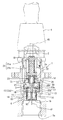
図1は、本発明の実施の形態に係るガス栓の通常の使用状態を示した断面図であり、ケーシング(1)は、上流側(図面では下側)から、ガス配管の継手(図示せず)が螺合接続される接続ネジ筒部(1a)と、過流出防止弁(6)が収容される小径部(1b)と、小径部(1b)よりも大径な大径部(1c)と、大径部(1c)よりも下流側に位置し且つプラグ部(2)が挿入されるプラグ挿入筒部(1d)が一直線上に連続する構成となっており、プラグ部(2)は、プラグ挿入筒部(1d)の下流側開放端(19)に形成されている雌ネジ部に、プラグ部(2)の中間位置に形成されている雄ネジ部を螺合させて接続されている。
なお、小径部(1b)と大径部(1c)との境界部分には、段部(18)が形成されている。
The gas plug according to the embodiment of the present invention has the plug portion (2) screw connected to the downstream open end of the casing (1) as in the conventional one.
FIG. 1 is a cross-sectional view showing a normal use state of the gas plug according to the embodiment of the present invention, and the casing (1) is a joint (shown in the drawing) of a gas pipe from the upstream side (lower side in the drawing). (1c), the small diameter portion (1b) in which the excess outflow prevention valve (6) is accommodated, and the large diameter portion (1c) larger than the small diameter portion (1b) And the plug insertion cylindrical portion (1d) located downstream of the large diameter portion (1c) and into which the plug portion (2) is inserted is continuous on a straight line, and the plug portion (2) Is connected to the female screw formed at the downstream open end (19) of the plug insertion cylinder (1d) by screwing the male screw formed at the middle position of the plug (2) ing.
A stepped portion (18) is formed at the boundary between the small diameter portion (1b) and the large diameter portion (1c).
プラグ部(2)内には、プラグ弁(21a)及びスライド栓(21b)からなる弁装置(21)が収容されていると共に、その上流側の、プラグ挿入筒部(1d)と大径部(1c)との境界部分におけるケーシング(1)内には、中央に中央孔(20a)と、その周囲の対向する各位置に一対の孔部(20b)が形成された金属製のバネ受け板(20)が固定されている。
また、プラグ部(2)には切欠部(2a)が形成されており、ガス流路は、接続ネジ筒部(1a)から、開弁状態にある過流出防止弁(6)内を通って、大径部(1c)、バネ受け板(20)の孔部(20b)、プラグ挿入筒部(1d)を通って、切欠部(2a)からプラグ部(2)の下流端へと連通する構成となっている。
ガス流路は、図2に示すように、過流出防止弁(6)が作動したときと、図3及び図4に示すように、弁装置(21)のプラグ弁(21a)によってプラグ部(2)の下流端が閉塞されたときに遮断される。
A valve device (21) consisting of a plug valve (21a) and a slide plug (21b) is accommodated in the plug portion (2), and a plug insertion cylinder portion (1d) and a large diameter portion on the upstream side thereof A metal spring support plate having a central hole (20a) at the center and a pair of holes (20b) at opposing positions around the central hole (20a) in the casing (1) at the boundary with (1c) (20) is fixed.
In addition, a notch (2a) is formed in the plug portion (2), and the gas flow path passes from the connecting screw cylinder portion (1a) through the inside of the excess outflow prevention valve (6) in the open state. , Through the large diameter portion (1c), the hole portion (20b) of the spring support plate (20), and the plug insertion cylindrical portion (1d) to communicate from the notch portion (2a) to the downstream end of the plug portion (2) It is a structure.
As shown in FIG. 2, the gas flow path is plugged by the plug valve (21a) of the valve device (21) when the excess outflow prevention valve (6) is operated and as shown in FIG. 3 and FIG. It is blocked when the downstream end of 2) is blocked.
弁装置(21)のスライド栓(21b)は、ソケット(4)内の押込み軸(40)によって奥へ押込まれるプラグ弁(21a)と一体的に移動可能で且つ上流側のバネ受け板(20)に向かって開放するバネ受け筒(22)を有している。
バネ受け筒(22)の底面とバネ受け板(20)との間には、弁装置(21)を、プラグ部(2)の閉塞方向に付勢する2本の外コイルバネ(24)が介在されている。
The slide plug (21b) of the valve device (21) is movable integrally with the plug valve (21a) which is pushed inward by the pushing shaft (40) in the socket (4) and an upstream spring receiving plate ( 20) has a spring receiver (22) that opens.
Between the bottom surface of the spring receiving cylinder (22) and the spring receiving plate (20), two external coil springs (24) for urging the valve device (21) in the closing direction of the plug portion (2) intervene It is done.
ケーシング(1)内にて、バネ受け板(20)の上流側には、大径部(1c)内を流路方向に移動可能な移動筒(10)が収容されており、移動筒(10)の中心部には、バネ受け板(20)の中央孔(20a)を上流側から下流側へ貫通する筒部(15)が、一対の支持片(17)(17)を介して突設されている(図9参照)。筒部(15)の内面に突設させた内側段部とスライド栓(21b)のバネ受け筒(22)の底部との間には、移動筒(10)を上流側に押し込むための押圧手段として押圧バネ(23)が介在されている。 In the casing (1), on the upstream side of the spring support plate (20), a movable cylinder (10) movable in the flow passage direction in the large diameter portion (1c) is accommodated. The cylindrical portion (15) which penetrates the central hole (20a) of the spring support plate (20) from the upstream side to the downstream side at the central portion of the) projects through the pair of support pieces (17) and (17) (See FIG. 9). A pressing means for pushing the movable barrel (10) upstream between the inner step portion provided on the inner surface of the barrel portion (15) and the bottom portion of the spring receiving barrel (22) of the slide plug (21b) As a pressure spring (23) is interposed.
移動筒(10)の上流側の内方には、環状凸部(11)が設けられ、移動筒(10)の外周面とケーシング(1)の大径部(1c)との間には、周壁部(12)が介在されており、これら環状凸部(11)と周壁部(12)とは、各々の上流側にて、環状底部(13)を介して連結されている。
なお、環状凸部(11)の内縁には、環状段部(14)が内方及び上流側に開放するように形成されている。この環状段部(14)の直径は、後述する過流出防止弁(6)のケース体(60)の下流端が嵌合可能な大きさに設定されている。
An annular convex portion (11) is provided on the upstream side of the moving cylinder (10), and between the outer peripheral surface of the moving cylinder (10) and the large diameter portion (1c) of the casing (1), Peripheral wall portions (12) are interposed, and the annular convex portion (11) and the peripheral wall portions (12) are connected via an annular bottom portion (13) on the upstream side of each.
At the inner edge of the annular convex portion (11), an annular stepped portion (14) is formed so as to open inward and upstream. The diameter of the annular step (14) is set to such a size that the downstream end of the case body (60) of the excess outflow prevention valve (6) described later can be fitted.
周壁部(12)には、図9に示すように、下流側へ開放する複数のスリットが形成されており、周壁部(12)で囲まれる空間内には、後述するリセット板(3)と、筒部(15)を具備する移動筒(10)が収容され、筒部(15)をバネ受け板(20)の中央孔(20a)に挿通させ、周壁部(12)のうち、相互に対向するように位置する一対の係合片(12a)(12a)を、バネ受け板(20)の外周縁の対向位置にそれぞれ設けた係合凹部(20c)(20c)に係合させれば、環状凸部(11)と、リセット板(3)と、移動筒(10)と、バネ受け板(20)とが一つのユニット体となり、移動筒(10)が周壁部(12)内にて流路方向に移動自在なリセット機構が構成される。 As shown in FIG. 9, the peripheral wall portion (12) is formed with a plurality of slits opened to the downstream side, and in the space surrounded by the peripheral wall portion (12), a reset plate (3) described later and A movable cylinder (10) having a cylindrical portion (15) is accommodated, and the cylindrical portion (15) is inserted into the central hole (20a) of the spring receiving plate (20), and the peripheral wall portions (12) are mutually If a pair of engaging pieces (12a) and (12a) positioned to face each other is engaged with engaging concave parts (20c) and (20c) provided at opposite positions of the outer peripheral edge of the spring receiving plate (20) The annular convex portion (11), the reset plate (3), the movable cylinder (10), and the spring receiving plate (20) form one unit body, and the movable cylinder (10) is in the peripheral wall portion (12) Thus, a reset mechanism movable in the flow direction is formed.
リセット板(3)は、図5に示すように、移動筒(10)の内径及び外径に略一致する内径及び外径を有するリング部(3a)と、リング部(3a)の一つの直径の一端から中心に向かって延設された帯状の押圧片(3b)と、前記直径の他端から押圧片(3b)よりも短く延設された小突片(3c)とからなり、全体は弾性材により形成されている。なお、押圧片(3b)及び小突片(3c)は、リング部(3a)の幅より僅かに幅広の帯状としているが、基部を太くしたテーパ状としてもよいし、スリット等の孔部を設けてもよい。
上記ユニット体において、リング部(3a)は移動筒(10)の上流側端面(10a)の上流側に位置し且つ、押圧片(3b)の基端部近傍域及び小突片(3c)は環状凸部(11)の下流側端面(11a)の下流側に位置し、移動筒(10)の上流側端面(10a)と環状凸部(11)の下流側端面(11a)との間に、リセット板(3)が扁平な初期状態に維持された状態でセットされ、図7に示すように、移動筒(10)の上流側端面(10a)がリング部(3a)に下流側から対接し、環状凸部(11)の下流側端面(11a)が押圧片(3b)の基端部近傍域及び小突片(3c)に上流側からに対接する。
As shown in FIG. 5, the reset plate (3) has a ring portion (3a) having an inner diameter and an outer diameter substantially corresponding to the inner diameter and the outer diameter of the movable cylinder (10), and a diameter of one of the ring portions (3a). A band-shaped pressing piece (3b) extending from the one end toward the center of the first and a small projecting piece (3c) extending shorter than the pressing piece (3b) from the other end of the diameter. It is formed of an elastic material. The pressing piece (3b) and the small protruding piece (3c) are formed in a band shape slightly wider than the width of the ring portion (3a), but may be tapered with a thick base, or a hole such as a slit You may provide.
In the unit body, the ring portion (3a) is located on the upstream side of the upstream end surface (10a) of the movable cylinder (10), and the proximal end vicinity region of the pressing piece (3b) and the small protruding piece (3c) The downstream end face (11a) of the annular convex portion (11) is located downstream of the upstream end face (10a) of the movable cylinder (10) and the downstream end face (11a) of the annular convex portion (11) The reset plate (3) is set in a flat initial state, and as shown in FIG. 7, the upstream end surface (10a) of the movable cylinder (10) is paired with the ring portion (3a) from the downstream side Contacting, the downstream end face (11a) of the annular convex part (11) comes in contact with the proximal end vicinity region of the pressing piece (3b) and the small protruding piece (3c) from the upstream side.
過流出防止弁(6)は、ケーシング(1)の小径部(1b)に収容されており、図8に示すように、樹脂製のケース体(60)内に、ガス圧によって、下流側へ移動する弁体(62)が収容されている。通常時においては、図8の(A)に示すように、弁体(62)は、バネ(64)の付勢力によって、弁座(63)から離反された状態に付勢されており、弁体(62)の中心に一体的に設けられているリセット軸(61)の下流側端部(61a)は、ケース体(60)の下流側には突出せず、上流側端面が上流側に突出している。 The excess outflow prevention valve (6) is accommodated in the small diameter portion (1b) of the casing (1), and as shown in FIG. 8, in the resin case body (60) A moving valve body (62) is accommodated. Under normal conditions, as shown in FIG. 8A, the valve body (62) is biased away from the valve seat (63) by the biasing force of the spring (64). The downstream end (61a) of the reset shaft (61) integrally provided at the center of the body (62) does not project to the downstream side of the case body (60), and the upstream end face is on the upstream side It protrudes.
プラグ部(2)内よりも下流側にて何らかの異常が発生してガスが過流出状態になると、過流出防止弁(6)が作動して、図8の(B)に示すように、弁体(62)が、バネ(64)の付勢力に抗して下流側へ押されて移動し、弁座(63)に圧着する。これが、過流出防止弁(6)の閉弁状態である。このとき、リセット軸(61)の下流側端部(61a)は、ケース体(60)の下流側から突出する。
この閉弁状態を解除するには、ケース体(60)の下流側に突出しているリセット軸(61)の下流側端部(61a)を内部へ押し込む。リセット軸(61)が押し込まれることにより、弁体(62)が上流側へ押されて移動させられ、それに伴い、弁体(62)の弁座(63)への圧着が解除されると同時に、バネ(64)の弾性復帰力によって、弁体(62)は、弁座(63)から離反された元の状態に復帰する。
If some abnormality occurs downstream of the plug portion (2) and the gas is in the overflow state, the overoutflow prevention valve (6) is actuated, as shown in (B) of FIG. The body (62) is pushed and moved downstream against the biasing force of the spring (64) and crimps to the valve seat (63). This is the closed state of the excess outflow prevention valve (6). At this time, the downstream end (61a) of the reset shaft (61) protrudes from the downstream side of the case body (60).
In order to release the closed valve state, the downstream end (61a) of the reset shaft (61) protruding to the downstream side of the case body (60) is pushed inward. As the reset shaft (61) is pushed, the valve body (62) is pushed and moved upstream, and at the same time the pressure bonding of the valve body (62) to the valve seat (63) is released. The elastic return force of the spring (64) restores the valve body (62) to the original state of being separated from the valve seat (63).
ケーシング(1)の小径部(1b)は、過流出防止弁(6)のケース体(60)が密に収容可能な大きさの円筒状に形成されていると共に、ケース体(60)の胴部中央から外方へ僅かに弾性的にテーパ状に張り出させた一対の突起(65)が、小径部(1b)の周面の対向位置に設けた一対の切欠溝(16)内にそれぞれ上流側からワンウェイ係合することにより、過流出防止弁(6)は、ケーシング(1)の小径部(1b)内に抜け止め状態に収容される。 The small diameter portion (1b) of the casing (1) is formed in a cylindrical shape large enough to accommodate the case body (60) of the excess outflow prevention valve (6) closely, and the body of the case body (60) A pair of projections (65) slightly outwardly protruding in a slightly elastic manner from the center of the part are respectively provided in a pair of cutout grooves (16) provided at opposite positions of the peripheral surface of the small diameter part (1b) By one way engagement from the upstream side, the excess outflow prevention valve (6) is accommodated in the small diameter portion (1b) of the casing (1) in a retaining state.
この実施の形態のガス栓(1)を組み立てるには、まず、ケーシング(1)の下流側から、環状凸部(11)とリセット板(3)と移動筒(10)とバネ受け板(20)とからなるユニット体を、環状底部(13)が段部(18)に対接するように収容する。 In order to assemble the gas plug (1) of this embodiment, first, from the downstream side of the casing (1), the annular convex portion (11), the reset plate (3), the movable cylinder (10) and the spring support plate (20) And the annular bottom portion (13) is in contact with the step portion (18).
その後、ケーシング(1)の下流側から、バネ受け板(20)の中央孔(20a)から下流側に突出している筒体(15)内に、押圧バネ(23)を収容すると共に、筒体(15)の外周側のバネ受け板(20)に外コイルバネ(24)をセットし、これら押圧バネ(23)及び外コイルバネ(24)の下流側端部が、スライド栓(21b)のバネ受け筒(22)内に収容されるように、弁装置(21)をプラグ部(2)内に収容させると共に、プラグ部(2)をケーシング(1)の下流側開放端(19)に螺合接続させる。そして、ケーシング(1)の接続ネジ筒部(1a)側から小径部(1b)内に過流出防止弁(6)を挿通し、環状段部(14)に過流出防止弁(6)のケース体(60)の下流端の周縁部を嵌め込むと、図4に示すように、閉弁方向に付勢されたプラグ部(2)内の弁装置(21)と、開弁状態の過流出防止弁(6)との間に、ユニット体が位置し、ユニット体の移動筒(10)と環状凸部(11)との間にて、リセット板(3)が扁平な初期状態にセットされた状態で、ガス栓の組み付けが完了する。 Thereafter, the pressure spring (23) is accommodated in the cylindrical body (15) which protrudes from the downstream side of the casing (1) to the downstream side from the central hole (20a) of the spring receiving plate (20) The outer coil spring (24) is set on the spring support plate (20) on the outer peripheral side of (15), and the downstream side end portions of the pressure spring (23) and the outer coil spring (24) The valve device (21) is housed in the plug portion (2) so as to be housed in the cylinder (22), and the plug portion (2) is screwed to the downstream open end (19) of the casing (1) Connect Then, the excess outflow prevention valve (6) is inserted into the small diameter part (1b) from the connection screw cylindrical part (1a) side of the casing (1), and the case of the excess outflow prevention valve (6) in the annular stepped part (14) When the peripheral portion of the downstream end of the body (60) is fitted, as shown in FIG. 4, the valve device (21) in the plug portion (2) biased in the valve closing direction and the excessive outflow of the valve opening state The unit body is positioned between the prevention valve (6), and the reset plate (3) is set in a flat initial state between the movable cylinder (10) of the unit body and the annular convex portion (11). In this state, the gas plug assembly is completed.
この状態から、ソケット(4)をプラグ部(2)に接続させると、図1に示すように、ソケット(4)内の押込み軸(40)によって弁装置(21)が、外コイルバネ(24)の付勢力に抗して奥へ押し込まれると同時に、筒体(15)が、押圧バネ(23)により上流側に押圧されて、移動筒(10)が筒体(15)と共に上流側へ移動する。
移動筒(10)の上流側端面(10a)が、環状凸部(11)の下流側端面(11a)よりも上流側に位置するまで上流側に移動することにより、両者間に位置するリセット板(3)は、図6に示すように、リング部(3a)は移動筒(10)の上流側端面(10a)で上流側に押されて上流側に突出し、押圧片(3b)は、その基端部近傍域が環状凸部(11)の下流側端面(11a)で押されて、先端が下流側に突出するように弾性変形する。
From this state, when the socket (4) is connected to the plug portion (2), as shown in FIG. 1, the valve device (21) is pushed by the pushing shaft (40) in the socket (4). The tube (15) is pushed upstream by the pressure spring (23) at the same time as it is pushed back against the biasing force of the cylinder, and the movable tube (10) moves upstream with the tube (15) Do.
A reset plate positioned between the moving cylinder (10) by moving upstream until the upstream end surface (10a) is positioned upstream of the downstream end surface (11a) of the annular convex portion (11) (3), as shown in FIG. 6, the ring portion (3a) is pushed upstream by the upstream end surface (10a) of the movable cylinder (10) and protrudes upstream, and the pressing piece (3b) is The proximal end vicinity region is pushed by the downstream end surface (11a) of the annular convex portion (11), and the distal end elastically deforms so as to project downstream.
ケーシング(1)の上流側から送られてくるガスは、過流出防止弁(6)、環状凸部(11)、リセット板(3)のリング部(3a)内、バネ受け板(20)の孔部(20b)、プラグ挿入筒部(1d)を通って、プラグ部(2)の下流端からソケット(4)を介して配管内へ流れていく。
なお、リセット板(3)のリング部(3a)内には押圧片(3b)と小突片(3c)が突出しているが、直径に亘って形成されておらず、下流側へ突出するように弾性変形するから、ガス流路の直径に亘って板バネを介在させた従来のものに比べて流路抵抗は確実に小さくなる。
The gas sent from the upstream side of the casing (1) is the excess outflow prevention valve (6), the annular convex portion (11), the ring portion (3a) of the reset plate (3), the spring receiving plate (20) The gas flows from the downstream end of the plug portion (2) into the pipe through the socket (4) through the hole (20b) and the plug insertion cylinder (1d).
Although the pressing piece (3b) and the small protruding piece (3c) are projected in the ring portion (3a) of the reset plate (3), they are not formed over the diameter but are projected to the downstream side Because of elastic deformation, the flow path resistance is surely reduced compared to the conventional one in which a plate spring is interposed over the diameter of the gas flow path.
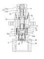
過流出防止弁(6)が作動して、図8の(B)に示す閉弁状態となった場合、過流出防止弁(6)内の弁体(62)がリセット軸(61)と共に、バネ(64)の付勢力に抗して、下流側へ移動させられ、リセット軸(61)の下流側端部(61a)がケース体(60)から下流側に突出する。リセット軸(61)の下流側端部(61a)が最突出状態にまで突出すると、図2及び図6に示すように、弾性変形状態にあるリセット板(3)のリング部(3a)の中心からリング部(3a)を超えて突出するが、押圧片(3b)の先端は、下流側へ最突出状態にあるリセット軸(61)の下流側端部(61a)よりもさらに下流側に位置する態様に弾性変形するように設定されているから、押圧片(3b)がリセット軸(61)の下流側端部(61a)に当接することはなく、リセット軸(61)の突出の邪魔になることはない。 When the overspill prevention valve (6) is operated and the valve closed state shown in FIG. 8B is obtained, the valve body (62) in the overspill prevention valve (6) is together with the reset shaft (61), It is moved to the downstream side against the biasing force of the spring (64), and the downstream end (61a) of the reset shaft (61) protrudes from the case body (60) to the downstream side. When the downstream end (61a) of the reset shaft (61) protrudes to the most projecting state, as shown in FIGS. 2 and 6, the center of the ring portion (3a) of the reset plate (3) in an elastically deformed state. Of the pressing piece (3b) is positioned further downstream than the downstream end (61a) of the reset shaft (61) in the most projecting state downstream of the ring portion (3a). And the pressing piece (3b) is not in contact with the downstream end (61a) of the reset shaft (61), but in the way of the projection of the reset shaft (61). It will never be.
過流出防止弁(6)が作動すると、下流側の異常の修復作業の際に安全面からソケット(4)がプラグ部(2)から外される。すると、図3に示すように、スライド栓(21b)は、外コイルバネ(24)の付勢力によって下流側に移動させられ、プラグ部(2)は、プラグ弁(21a)によって閉塞される。弁装置(21)が下流側に移動することにより、押圧バネ(23)による筒部(15)及び移動筒(10)を上流側に押圧していた押圧力が解除される。これにより、リセット板(3)は弾性復帰し、移動筒(10)はリング部(3a)の弾性復帰力によって下流側に移動すると同時に、下流側へ突出状態に付勢されていた押圧片(3b)が扁平な初期状態に弾性復帰し、このときの押圧片(3b)の弾性復帰力によって、リセット軸(61)の下流側端部(61a)がケース体(60)内に押し込まれる。 When the overspill prevention valve (6) is activated, the socket (4) is removed from the plug portion (2) from the viewpoint of safety during repair work of the downstream abnormality. Then, as shown in FIG. 3, the slide plug (21b) is moved downstream by the biasing force of the outer coil spring (24), and the plug portion (2) is closed by the plug valve (21a). By moving the valve device (21) to the downstream side, the pressing force by which the cylindrical portion (15) and the movable cylinder (10) by the pressing spring (23) are pressed to the upstream side is released. As a result, the reset plate (3) elastically returns, and the movable cylinder (10) moves downstream by the elastic return force of the ring portion (3a), and at the same time, the pressing piece is urged to protrude downstream 3b) elastically returns to a flat initial state, and the downstream end (61a) of the reset shaft (61) is pushed into the case body (60) by the elastic return force of the pressing piece (3b) at this time.
過流出防止弁(6)内のリセット軸(61)の下流側端部(61a)が上流側へ押し込まれると、弁体(62)の弁座(63)への圧着が解除されると同時に、バネ(64)の付勢力によって、図4及び図8の(A)に示すように、過流出防止弁(6)は開弁させられ、初期状態にリセットさせられる。
このように、下流側へ突出状態にあるリセット軸(61)の下流側端部(61a)を上流側へ押す押圧片(3b)を有するリセット板(3)と、リセット板(3)を弾性変形させる環状凸部(11)と移動筒(10)とで、過流出防止弁のリセット機構が構成されることとなる。
When the downstream end (61a) of the reset shaft (61) in the excess outflow prevention valve (6) is pushed upstream, the pressure bonding of the valve body (62) to the valve seat (63) is simultaneously released. The biasing force of the spring (64) causes the excess outflow prevention valve (6) to be opened and reset to the initial state as shown in FIGS. 4 and 8A.
Thus, the reset plate (3) having the pressing piece (3b) pressing the downstream end (61a) of the reset shaft (61) in the protruding state to the downstream side in the upstream direction, and the reset plate (3) The annular convex portion (11) to be deformed and the movable cylinder (10) constitute a reset mechanism of the excess outflow prevention valve.
なお、ソケット(4)の押込み軸(40)でプラグ弁(21a)を奥へ押したときに、スライド栓(21b)と筒体(15)内の内側段部との間に介在させた押圧バネ(23)で、筒体(15)及びこれと一体の移動筒(10)が、リセット体(3)を弾性変形させながら、上流側に移動可能となるように、押圧バネ(23)による筒体(15)の押圧力は、リセット体(3)の弾性力よりも大きく設定されている。
また、図2の状態から、ソケット(4)を取り外して、弁装置(21)が外コイルバネ(24)の弾性復帰力によりプラグ部(2)を閉弁させる下流側へ移動させられると、リセット体(3)の弾性復帰力によって、移動筒(10)は環状凸部(11)よりも下流側に位置するまで下流側へ移動させられるように設定されている。
なお、移動筒(10)を筒部(15)と共に上流側に押圧させるための押圧手段として、押圧バネ(23)を設ける構成としたから、プラグ部(2)へのソケットの接続に際し、スライド栓(21b)の移動量と移動筒(10)の移動量との間の差を押圧バネ(23)の弾性によって調節及び吸収することができる。
In addition, when the plug valve (21a) is pushed back by the pushing shaft (40) of the socket (4), the pressure interposed between the slide plug (21b) and the inner step portion in the cylinder (15) By the spring (23), the cylinder (15) and the movable cylinder (10) integral therewith are moved by the pressing spring (23) so that the reset body (3) can be moved upstream while being elastically deformed The pressing force of the cylindrical body (15) is set larger than the elastic force of the reset body (3).
Also, when the socket (4) is removed from the state shown in FIG. 2 and the valve device (21) is moved downstream to close the plug (2) by the elastic return force of the outer coil spring (24) The movable barrel (10) is set to be moved downstream until it is positioned downstream of the annular convex portion (11) by the elastic return force of the body (3).
In addition, since the pressing spring (23) is provided as pressing means for pressing the movable barrel (10) together with the barrel portion (15) to the upstream side, the slide is performed when connecting the socket to the plug portion (2) The difference between the amount of movement of the bung (21b) and the amount of movement of the movable barrel (10) can be adjusted and absorbed by the elasticity of the pressure spring (23).
上記実施の形態のガス栓では、上記したように、リセット軸(61)を押し込むためのリセット板(3)の押圧片(3b)を、半径程度の長さの帯状とし、しかも、プラグ部(2)の開弁状態にて、下流側へ突出するように変形可能としたから、ガス流路の直径全域に沿って板バネを架設させた従来のものに比べて、流路抵抗を低減させることができ、ガスの流れを向上させることができる。
また、押圧片(3b)の先端の突出度合いは、一枚の板バネを湾曲させたときの湾曲度合いよりも変位量を大きくとることができるので、作動した過流出防止弁(6)から突出するリセット軸(61)の突出度合いの誤差を吸収し、過流出防止弁(6)の作動時にリセット軸(61)の下流側端部(61a)に押圧片(3b)が当接して過流出防止弁(6)の閉弁作動を阻害することを確実に防止することができる。
In the gas plug of the above-described embodiment, as described above, the pressing piece (3b) of the reset plate (3) for pushing the reset shaft (61) is in the shape of a band of about the radius and the plug portion ( Since it is deformable so as to project downstream in the valve open state of 2), the flow path resistance is reduced compared to the conventional one in which a flat spring is installed along the entire diameter of the gas flow path. And the flow of gas can be improved.
In addition, since the degree of protrusion of the tip of the pressing piece (3b) can be made larger than the degree of bending when one leaf spring is bent, it protrudes from the operated excess outflow prevention valve (6) Absorbs the error of the degree of protrusion of the reset shaft (61), and the pressure piece (3b) abuts against the downstream end (61a) of the reset shaft (61) when the excess outflow prevention valve (6) is actuated It is possible to reliably prevent inhibition of the closing operation of the prevention valve (6).
(1) ・・・・・・・・・・・・ケーシング
(10)・・・・・・・・・・・・移動筒
(10a) ・・・・・・・・・・・上流側端面
(11)・・・・・・・・・・・・環状凸部
(11a) ・・・・・・・・・・・下流側端面
(2) ・・・・・・・・・・・・プラグ部
(20)・・・・・・・・・・・・バネ受け板
(21)・・・・・・・・・・・・弁装置
(3) ・・・・・・・・・・・・リセット板
(3a)・・・・・・・・・・・・リング部
(3b)・・・・・・・・・・・・押圧片
(4) ・・・・・・・・・・・・ソケット
(6) ・・・・・・・・・・・・過流出防止弁
(61)・・・・・・・・・・・・リセット軸
(1) ・ ・ ・ ・ ・ ・ ・ ・ ・ ・ ・ ・ ・ Casing
(10) ........... Moveable cylinder
(10a) ················· ··
(11).
(11a) ······································
(2) ・ ・ ・ ・ ・ ・ ・ ・ ・ ・ ・ ・ ・ ・ Plug part
(20) ··············· Spring support plate
(21) ........... The valve device
(3) ・ ・ ・ ・ ・ ・ ・ ・ ・ ・ ・ ・ ・ ・ ・ Reset board
(3a) ················ Ring part
(3b) ·······························
(4) ······················ Socket
(6) · · · · · · · · · · · · · · · · excess outflow prevention valve
(61) .............. Reset axis
Claims (4)
プラグ部を閉塞する方向に付勢され且つソケットがプラグ部に接続されると開弁する弁装置と、
前記弁装置の上流側に設けられ且つガス流路に一定以上のガスが流れたときガス流路を自動的に遮断する過流出防止弁と、
前記弁装置と過流出防止弁との間に設けられ且つ作動後の過流出防止弁を初期状態に復帰させるリセット機構とが備えられているガス栓において、
リセット機構は、過流出防止弁より下流側へ突出する環状凸部と、前記環状凸部と弁装置との間に設けられ且つ環状凸部の外径より大きな内径を有すると共に弁装置と同方向にケーシング内を進退移動する移動筒と、前記移動筒と環状凸部との間に介在され且つ前記移動筒に略一致する内径及び外径を有するリング部と前記リング部の中心に向かって延設されている帯状の押圧片とからなる弾性材製のリセット板とを備え、
弁装置の閉弁時には、移動筒の上流側端面とこれより上流側に位置する環状凸部の下流側端面との間で、リセット板は扁平な初期状態に維持され、
弁装置の開弁時には、移動筒が上流側に移動して、移動筒の上流側端面が環状凸部の下流側端面より上流側へ位置することにより、リセット板は押圧片が下流側に突出する形状に弾性変形し、
過流出防止弁は、作動時に下流側へ突出するリセット軸を有すると共に、押圧片の突出度合いは、最突出状態にあるリセット軸の下流側端部より下流側に押圧片の先端が位置するように設定され、前記リセット軸は、押圧片の弾性復帰力で上流側へ押圧されて初期位置へ戻ることを特徴とするガス栓。 A gas plug in which a straight gas flow path is formed from the upstream open end of the casing to the downstream open end to which the plug portion is connected,
A valve device biased in a direction closing the plug portion and opening when the socket is connected to the plug portion;
An excess outflow prevention valve which is provided on the upstream side of the valve device and which automatically shuts off the gas flow path when a gas of a predetermined level or more flows in the gas flow path;
A gas plug provided between the valve device and the over spill prevention valve and provided with a reset mechanism for returning the over spill prevention valve after actuation to an initial state,
The reset mechanism is provided between the annular convex portion projecting to the downstream side with respect to the excessive outflow prevention valve, and between the annular convex portion and the valve device, and has an inner diameter larger than the outer diameter of the annular convex portion And a ring portion interposed between the moving cylinder and the annular convex portion and having an inner diameter and an outer diameter substantially corresponding to the moving cylinder, and extending toward the center of the ring portion And a reset plate made of an elastic material comprising a strip-shaped pressing piece provided,
During valve closing of the valve device, the reset plate is maintained in a flat initial state between the upstream end surface of the movable cylinder and the downstream end surface of the annular convex portion located upstream therefrom.
When the valve device is opened, the movable cylinder moves upstream, and the upstream end surface of the movable cylinder is positioned upstream of the downstream end surface of the annular convex portion, so that the pressing plate protrudes in the downstream side of the reset plate Elastically deform to the shape
The excess outflow prevention valve has a reset shaft that protrudes downstream when actuated, and the degree of protrusion of the pressing piece is such that the tip of the pressing piece is positioned downstream of the downstream end of the reset shaft in the most projecting state. And the reset shaft is pressed upstream by the elastic return force of the pressing piece to return to the initial position.
前記環状凸部の外方に、環状凸部より下流側へ突出する周壁部が同心状に設けられると共に、環状凸部と周壁部とはその上流側にて環状底部を介して連設され、
前記周壁部内にリセット板と移動筒を収容した状態にて、前記周壁部の下流側端部がバネ受け板に係合させたガス栓。 The gas plug according to claim 1, wherein a spring receiving plate for receiving a spring for biasing the valve device in a valve closing direction is fixed in the casing,
A peripheral wall portion projecting to the downstream side from the annular convex portion is concentrically provided on the outer side of the annular convex portion, and the annular convex portion and the peripheral wall portion are continuously provided on the upstream side via an annular bottom portion.
The gas plug in which the downstream end of the peripheral wall is engaged with the spring support plate in a state in which the reset plate and the movable cylinder are accommodated in the peripheral wall.
Priority Applications (1)
| Application Number | Priority Date | Filing Date | Title |
|---|---|---|---|
| JP2015150772A JP6501664B2 (en) | 2015-07-30 | 2015-07-30 | Gas valve |
Applications Claiming Priority (1)
| Application Number | Priority Date | Filing Date | Title |
|---|---|---|---|
| JP2015150772A JP6501664B2 (en) | 2015-07-30 | 2015-07-30 | Gas valve |
Publications (2)
| Publication Number | Publication Date |
|---|---|
| JP2017032027A JP2017032027A (en) | 2017-02-09 |
| JP6501664B2 true JP6501664B2 (en) | 2019-04-17 |
Family
ID=57985907
Family Applications (1)
| Application Number | Title | Priority Date | Filing Date |
|---|---|---|---|
| JP2015150772A Active JP6501664B2 (en) | 2015-07-30 | 2015-07-30 | Gas valve |
Country Status (1)
| Country | Link |
|---|---|
| JP (1) | JP6501664B2 (en) |
Family Cites Families (3)
| Publication number | Priority date | Publication date | Assignee | Title |
|---|---|---|---|---|
| JPS6126689Y2 (en) * | 1978-06-06 | 1986-08-09 | ||
| JP3089442B2 (en) * | 1992-06-08 | 2000-09-18 | 株式会社藤井合金製作所 | Overflow prevention valve reset device |
| JP5836168B2 (en) * | 2011-03-16 | 2015-12-24 | 大阪瓦斯株式会社 | Gas stopper |
-
2015
- 2015-07-30 JP JP2015150772A patent/JP6501664B2/en active Active
Also Published As
| Publication number | Publication date |
|---|---|
| JP2017032027A (en) | 2017-02-09 |
Similar Documents
| Publication | Publication Date | Title |
|---|---|---|
| JP6231843B2 (en) | Misfueling prevention device | |
| JP2004169919A (en) | Quick coupler for separably connecting two pipe | |
| JP6501664B2 (en) | Gas valve | |
| JP6489956B2 (en) | Gas stopper | |
| US20170036535A1 (en) | Fuel filling aperture opening and closing device | |
| JP6537247B2 (en) | Gas stopper with overspill prevention mechanism | |
| KR101827688B1 (en) | Fuel tank check valve | |
| JP5518029B2 (en) | Water heater with valve and valve | |
| JP6116255B2 (en) | Gas stopper | |
| JP4768765B2 (en) | Overflow prevention valve device for gas stopper | |
| JP5894746B2 (en) | Gas stopper | |
| JP6305118B2 (en) | Gas tap with fuse | |
| JP6192996B2 (en) | Gas stopper | |
| JP6143519B2 (en) | Gas stopper | |
| JP6314016B2 (en) | Overflow prevention valve | |
| JP6087691B2 (en) | Gas stopper | |
| JP4976175B2 (en) | Gas supply connector | |
| JP2005024076A (en) | Gas plug | |
| JP6116981B2 (en) | Sub-closure device for fuel filler closure device | |
| JP4278993B2 (en) | Ball valve | |
| JP5670108B2 (en) | Gas stopper | |
| JP6624995B2 (en) | Check valve | |
| JP6265785B2 (en) | Gas tap with fuse | |
| JP2560258Y2 (en) | Gas cock | |
| JP6494456B2 (en) | Governor |
Legal Events
| Date | Code | Title | Description |
|---|---|---|---|
| A621 | Written request for application examination |
Free format text: JAPANESE INTERMEDIATE CODE: A621 Effective date: 20180404 |
|
| A977 | Report on retrieval |
Free format text: JAPANESE INTERMEDIATE CODE: A971007 Effective date: 20190219 |
|
| TRDD | Decision of grant or rejection written | ||
| A01 | Written decision to grant a patent or to grant a registration (utility model) |
Free format text: JAPANESE INTERMEDIATE CODE: A01 Effective date: 20190226 |
|
| A61 | First payment of annual fees (during grant procedure) |
Free format text: JAPANESE INTERMEDIATE CODE: A61 Effective date: 20190319 |
|
| R150 | Certificate of patent or registration of utility model |
Ref document number: 6501664 Country of ref document: JP Free format text: JAPANESE INTERMEDIATE CODE: R150 |
|
| R250 | Receipt of annual fees |
Free format text: JAPANESE INTERMEDIATE CODE: R250 |
|
| S531 | Written request for registration of change of domicile |
Free format text: JAPANESE INTERMEDIATE CODE: R313532 |
|
| R350 | Written notification of registration of transfer |
Free format text: JAPANESE INTERMEDIATE CODE: R350 |